EP3677402A1 - Molding-machine cylinder and method for producing same - Google Patents
Molding-machine cylinder and method for producing same Download PDFInfo
- Publication number
- EP3677402A1 EP3677402A1 EP18852688.3A EP18852688A EP3677402A1 EP 3677402 A1 EP3677402 A1 EP 3677402A1 EP 18852688 A EP18852688 A EP 18852688A EP 3677402 A1 EP3677402 A1 EP 3677402A1
- Authority
- EP
- European Patent Office
- Prior art keywords
- tungsten carbide
- based alloy
- lining layer
- cylinder
- volume
- Prior art date
- Legal status (The legal status is an assumption and is not a legal conclusion. Google has not performed a legal analysis and makes no representation as to the accuracy of the status listed.)
- Granted
Links
Images




Classifications
-
- B—PERFORMING OPERATIONS; TRANSPORTING
- B22—CASTING; POWDER METALLURGY
- B22F—WORKING METALLIC POWDER; MANUFACTURE OF ARTICLES FROM METALLIC POWDER; MAKING METALLIC POWDER; APPARATUS OR DEVICES SPECIALLY ADAPTED FOR METALLIC POWDER
- B22F3/00—Manufacture of workpieces or articles from metallic powder characterised by the manner of compacting or sintering; Apparatus specially adapted therefor ; Presses and furnaces
- B22F3/003—Apparatus, e.g. furnaces
-
- B—PERFORMING OPERATIONS; TRANSPORTING
- B22—CASTING; POWDER METALLURGY
- B22F—WORKING METALLIC POWDER; MANUFACTURE OF ARTICLES FROM METALLIC POWDER; MAKING METALLIC POWDER; APPARATUS OR DEVICES SPECIALLY ADAPTED FOR METALLIC POWDER
- B22F3/00—Manufacture of workpieces or articles from metallic powder characterised by the manner of compacting or sintering; Apparatus specially adapted therefor ; Presses and furnaces
- B22F3/004—Filling molds with powder
-
- B—PERFORMING OPERATIONS; TRANSPORTING
- B22—CASTING; POWDER METALLURGY
- B22F—WORKING METALLIC POWDER; MANUFACTURE OF ARTICLES FROM METALLIC POWDER; MAKING METALLIC POWDER; APPARATUS OR DEVICES SPECIALLY ADAPTED FOR METALLIC POWDER
- B22F3/00—Manufacture of workpieces or articles from metallic powder characterised by the manner of compacting or sintering; Apparatus specially adapted therefor ; Presses and furnaces
- B22F3/02—Compacting only
- B22F3/03—Press-moulding apparatus therefor
-
- B—PERFORMING OPERATIONS; TRANSPORTING
- B22—CASTING; POWDER METALLURGY
- B22F—WORKING METALLIC POWDER; MANUFACTURE OF ARTICLES FROM METALLIC POWDER; MAKING METALLIC POWDER; APPARATUS OR DEVICES SPECIALLY ADAPTED FOR METALLIC POWDER
- B22F5/00—Manufacture of workpieces or articles from metallic powder characterised by the special shape of the product
- B22F5/007—Manufacture of workpieces or articles from metallic powder characterised by the special shape of the product of moulds
-
- B—PERFORMING OPERATIONS; TRANSPORTING
- B22—CASTING; POWDER METALLURGY
- B22F—WORKING METALLIC POWDER; MANUFACTURE OF ARTICLES FROM METALLIC POWDER; MAKING METALLIC POWDER; APPARATUS OR DEVICES SPECIALLY ADAPTED FOR METALLIC POWDER
- B22F5/00—Manufacture of workpieces or articles from metallic powder characterised by the special shape of the product
- B22F5/10—Manufacture of workpieces or articles from metallic powder characterised by the special shape of the product of articles with cavities or holes, not otherwise provided for in the preceding subgroups
-
- B—PERFORMING OPERATIONS; TRANSPORTING
- B22—CASTING; POWDER METALLURGY
- B22F—WORKING METALLIC POWDER; MANUFACTURE OF ARTICLES FROM METALLIC POWDER; MAKING METALLIC POWDER; APPARATUS OR DEVICES SPECIALLY ADAPTED FOR METALLIC POWDER
- B22F7/00—Manufacture of composite layers, workpieces, or articles, comprising metallic powder, by sintering the powder, with or without compacting wherein at least one part is obtained by sintering or compression
- B22F7/06—Manufacture of composite layers, workpieces, or articles, comprising metallic powder, by sintering the powder, with or without compacting wherein at least one part is obtained by sintering or compression of composite workpieces or articles from parts, e.g. to form tipped tools
- B22F7/08—Manufacture of composite layers, workpieces, or articles, comprising metallic powder, by sintering the powder, with or without compacting wherein at least one part is obtained by sintering or compression of composite workpieces or articles from parts, e.g. to form tipped tools with one or more parts not made from powder
-
- B—PERFORMING OPERATIONS; TRANSPORTING
- B29—WORKING OF PLASTICS; WORKING OF SUBSTANCES IN A PLASTIC STATE IN GENERAL
- B29C—SHAPING OR JOINING OF PLASTICS; SHAPING OF MATERIAL IN A PLASTIC STATE, NOT OTHERWISE PROVIDED FOR; AFTER-TREATMENT OF THE SHAPED PRODUCTS, e.g. REPAIRING
- B29C33/00—Moulds or cores; Details thereof or accessories therefor
- B29C33/38—Moulds or cores; Details thereof or accessories therefor characterised by the material or the manufacturing process
-
- B—PERFORMING OPERATIONS; TRANSPORTING
- B29—WORKING OF PLASTICS; WORKING OF SUBSTANCES IN A PLASTIC STATE IN GENERAL
- B29C—SHAPING OR JOINING OF PLASTICS; SHAPING OF MATERIAL IN A PLASTIC STATE, NOT OTHERWISE PROVIDED FOR; AFTER-TREATMENT OF THE SHAPED PRODUCTS, e.g. REPAIRING
- B29C45/00—Injection moulding, i.e. forcing the required volume of moulding material through a nozzle into a closed mould; Apparatus therefor
- B29C45/17—Component parts, details or accessories; Auxiliary operations
- B29C45/46—Means for plasticising or homogenising the moulding material or forcing it into the mould
- B29C45/58—Details
- B29C45/62—Barrels or cylinders
-
- B—PERFORMING OPERATIONS; TRANSPORTING
- B29—WORKING OF PLASTICS; WORKING OF SUBSTANCES IN A PLASTIC STATE IN GENERAL
- B29C—SHAPING OR JOINING OF PLASTICS; SHAPING OF MATERIAL IN A PLASTIC STATE, NOT OTHERWISE PROVIDED FOR; AFTER-TREATMENT OF THE SHAPED PRODUCTS, e.g. REPAIRING
- B29C48/00—Extrusion moulding, i.e. expressing the moulding material through a die or nozzle which imparts the desired form; Apparatus therefor
- B29C48/25—Component parts, details or accessories; Auxiliary operations
- B29C48/36—Means for plasticising or homogenising the moulding material or forcing it through the nozzle or die
- B29C48/50—Details of extruders
- B29C48/68—Barrels or cylinders
- B29C48/6803—Materials, coating or lining therefor
-
- C—CHEMISTRY; METALLURGY
- C22—METALLURGY; FERROUS OR NON-FERROUS ALLOYS; TREATMENT OF ALLOYS OR NON-FERROUS METALS
- C22C—ALLOYS
- C22C29/00—Alloys based on carbides, oxides, nitrides, borides, or silicides, e.g. cermets, or other metal compounds, e.g. oxynitrides, sulfides
- C22C29/02—Alloys based on carbides, oxides, nitrides, borides, or silicides, e.g. cermets, or other metal compounds, e.g. oxynitrides, sulfides based on carbides or carbonitrides
- C22C29/06—Alloys based on carbides, oxides, nitrides, borides, or silicides, e.g. cermets, or other metal compounds, e.g. oxynitrides, sulfides based on carbides or carbonitrides based on carbides, but not containing other metal compounds
- C22C29/067—Alloys based on carbides, oxides, nitrides, borides, or silicides, e.g. cermets, or other metal compounds, e.g. oxynitrides, sulfides based on carbides or carbonitrides based on carbides, but not containing other metal compounds comprising a particular metallic binder
-
- C—CHEMISTRY; METALLURGY
- C22—METALLURGY; FERROUS OR NON-FERROUS ALLOYS; TREATMENT OF ALLOYS OR NON-FERROUS METALS
- C22C—ALLOYS
- C22C29/00—Alloys based on carbides, oxides, nitrides, borides, or silicides, e.g. cermets, or other metal compounds, e.g. oxynitrides, sulfides
- C22C29/02—Alloys based on carbides, oxides, nitrides, borides, or silicides, e.g. cermets, or other metal compounds, e.g. oxynitrides, sulfides based on carbides or carbonitrides
- C22C29/06—Alloys based on carbides, oxides, nitrides, borides, or silicides, e.g. cermets, or other metal compounds, e.g. oxynitrides, sulfides based on carbides or carbonitrides based on carbides, but not containing other metal compounds
- C22C29/08—Alloys based on carbides, oxides, nitrides, borides, or silicides, e.g. cermets, or other metal compounds, e.g. oxynitrides, sulfides based on carbides or carbonitrides based on carbides, but not containing other metal compounds based on tungsten carbide
-
- C—CHEMISTRY; METALLURGY
- C23—COATING METALLIC MATERIAL; COATING MATERIAL WITH METALLIC MATERIAL; CHEMICAL SURFACE TREATMENT; DIFFUSION TREATMENT OF METALLIC MATERIAL; COATING BY VACUUM EVAPORATION, BY SPUTTERING, BY ION IMPLANTATION OR BY CHEMICAL VAPOUR DEPOSITION, IN GENERAL; INHIBITING CORROSION OF METALLIC MATERIAL OR INCRUSTATION IN GENERAL
- C23C—COATING METALLIC MATERIAL; COATING MATERIAL WITH METALLIC MATERIAL; SURFACE TREATMENT OF METALLIC MATERIAL BY DIFFUSION INTO THE SURFACE, BY CHEMICAL CONVERSION OR SUBSTITUTION; COATING BY VACUUM EVAPORATION, BY SPUTTERING, BY ION IMPLANTATION OR BY CHEMICAL VAPOUR DEPOSITION, IN GENERAL
- C23C24/00—Coating starting from inorganic powder
- C23C24/08—Coating starting from inorganic powder by application of heat or pressure and heat
- C23C24/082—Coating starting from inorganic powder by application of heat or pressure and heat without intermediate formation of a liquid in the layer
- C23C24/085—Coating with metallic material, i.e. metals or metal alloys, optionally comprising hard particles, e.g. oxides, carbides or nitrides
-
- B—PERFORMING OPERATIONS; TRANSPORTING
- B22—CASTING; POWDER METALLURGY
- B22F—WORKING METALLIC POWDER; MANUFACTURE OF ARTICLES FROM METALLIC POWDER; MAKING METALLIC POWDER; APPARATUS OR DEVICES SPECIALLY ADAPTED FOR METALLIC POWDER
- B22F5/00—Manufacture of workpieces or articles from metallic powder characterised by the special shape of the product
- B22F5/10—Manufacture of workpieces or articles from metallic powder characterised by the special shape of the product of articles with cavities or holes, not otherwise provided for in the preceding subgroups
- B22F2005/103—Cavity made by removal of insert
-
- B—PERFORMING OPERATIONS; TRANSPORTING
- B22—CASTING; POWDER METALLURGY
- B22F—WORKING METALLIC POWDER; MANUFACTURE OF ARTICLES FROM METALLIC POWDER; MAKING METALLIC POWDER; APPARATUS OR DEVICES SPECIALLY ADAPTED FOR METALLIC POWDER
- B22F2301/00—Metallic composition of the powder or its coating
- B22F2301/15—Nickel or cobalt
-
- B—PERFORMING OPERATIONS; TRANSPORTING
- B22—CASTING; POWDER METALLURGY
- B22F—WORKING METALLIC POWDER; MANUFACTURE OF ARTICLES FROM METALLIC POWDER; MAKING METALLIC POWDER; APPARATUS OR DEVICES SPECIALLY ADAPTED FOR METALLIC POWDER
- B22F2302/00—Metal Compound, non-Metallic compound or non-metal composition of the powder or its coating
- B22F2302/10—Carbide
-
- B—PERFORMING OPERATIONS; TRANSPORTING
- B22—CASTING; POWDER METALLURGY
- B22F—WORKING METALLIC POWDER; MANUFACTURE OF ARTICLES FROM METALLIC POWDER; MAKING METALLIC POWDER; APPARATUS OR DEVICES SPECIALLY ADAPTED FOR METALLIC POWDER
- B22F2304/00—Physical aspects of the powder
- B22F2304/10—Micron size particles, i.e. above 1 micrometer up to 500 micrometer
-
- B—PERFORMING OPERATIONS; TRANSPORTING
- B22—CASTING; POWDER METALLURGY
- B22F—WORKING METALLIC POWDER; MANUFACTURE OF ARTICLES FROM METALLIC POWDER; MAKING METALLIC POWDER; APPARATUS OR DEVICES SPECIALLY ADAPTED FOR METALLIC POWDER
- B22F2998/00—Supplementary information concerning processes or compositions relating to powder metallurgy
- B22F2998/10—Processes characterised by the sequence of their steps
-
- B—PERFORMING OPERATIONS; TRANSPORTING
- B22—CASTING; POWDER METALLURGY
- B22F—WORKING METALLIC POWDER; MANUFACTURE OF ARTICLES FROM METALLIC POWDER; MAKING METALLIC POWDER; APPARATUS OR DEVICES SPECIALLY ADAPTED FOR METALLIC POWDER
- B22F2999/00—Aspects linked to processes or compositions used in powder metallurgy
Definitions
- the present invention relates to a molding machine cylinder having a composite structure comprising a lining layer having excellent wear resistance, corrosion resistance and machinability, which is mainly used in injection-molding or extrusion-molding machines for plastics.
- cylinders used for machines for injection-molding or extrusion-molding plastics, etc. withstand wear by resins, additives, etc. during high-temperature molding, and can be produced at lower cost.
- a molding machine cylinder having a bimetal structure comprising a lining layer having tungsten carbide particles dispersed in a nickel alloy matrix, which is formed by a centrifugal casting method on an inner surface of a steel-made circular cylinder, has conventionally been used.
- molding machine cylinders are exposed to severe wear and corrosion.
- the reinforced plastics exert severe wear by their glass fibers or inorganic fillers, and the flame-retardant plastics exert severe corrosion by isolated halogens
- JP H5-269813 A discloses a composite cylinder for high-temperature, high-pressure molding, which comprises a cylinder body of heat-resistant martensitic steel, and a lining layer of a Ni-based alloy containing tungsten carbide particles, the lining layer being formed by uniformly dispersing 5-60 parts by weight [2.8-25.5% by volume (converted by calculation using that the Ni-based alloy has a density of 8.9 g/cm 3 , and the tungsten carbide has a density of 15.6 g/cm 3 , the same is true below)] of tungsten carbide particles having particle sizes of 5-100 ⁇ m in 100 parts by weight of atomized Ni-based alloy powder having wear resistance and corrosion resistance, and pressure-sintering the lining layer on the inner surface of the cylinder body by HIP.
- JP S61-218869 A discloses a cylinder having excellent wear resistance and corrosion resistance, which has a two-layer structure in which an inner layer of a sintered Ni-based alloy containing 30-95% by mass [20-92% by volume (converted)] of tungsten carbide particles is integrally fused to an inner surface of a metal cylinder as an outer layer by HIP.
- JP S61-218869 A describes that the tungsten carbide particles preferably have particle sizes of 1-30 ⁇ m from the aspect of surface roughening resistance.
- an object of the present invention is to provide a molding machine cylinder comprising a lining layer having excellent wear resistance, corrosion resistance and machinability and suffering no deterioration of mechanical strength even when the amount of tungsten carbide particles is increased, and its production method.
- the inventors have conducted intensive research on a HIPed lining layer of a Ni-based alloy containing tungsten carbide particles, finding that when the structure of the lining layer is optimized, the lining layer can be provided with improved wear resistance and corrosion resistance as well as excellent machinability, without suffering the deterioration of mechanical strength even when the percentage of tungsten carbide particles is increased.
- the present invention has been completed based on such finding.
- the molding machine cylinder of the present invention comprises a HIP-sintered lining layer formed on an inner surface of a cylindrical steel body, the lining layer comprising 38-70% by volume of tungsten carbide particles having a median diameter d 50 of 1-7 ⁇ m and a matrix composed of an Ni-based alloy, and the maximum length of the matrix in an arbitrary cross section being 12 ⁇ m or less.
- the tungsten carbide particles preferably have d 10 of 0.5-3 ⁇ m and d 90 of 5-15 ⁇ m, wherein d 10 and d 90 are particle sizes at cumulative volumes corresponding to 10% and 90%, respectively, of the total volume, in a curve expressing the relation between the particle size and cumulative volume (value obtained by accumulating the volume of particles having sizes up to a particular size) of tungsten carbide particles.
- the matrix composed of an Ni-based alloy preferably contains by mass 1-7% of Si, 5-20% of Cr, and 1-4% of B.
- the matrix composed of an Ni-based alloy preferably contains at least one of less than 0.13% of C, 1.5% or less of Mn, 12% or less of Co, 1% or less of Fe, and 0.1% or less of Mo.
- the lining layer preferably contains 45-60% by volume of the tungsten carbide particles.
- the method of the present invention for producing a cylinder for a molding machine comprises the steps of arranging a steel mandrel inside a cylindrical steel body to form a space between an inner surface of the cylindrical body and the mandrel; filling the space with a powdery mixture comprising tungsten carbide powder and Ni-based alloy powder at a volume ratio of 38/62 to 70/30; evacuating and sealing the space containing the powdery mixture, and then subjecting the powdery mixture to HIP to obtain a composite cylinder whose cylindrical body is lined with the Ni-based alloy containing tungsten carbide particles; and machining the resultant composite cylinder; the tungsten carbide powder having a median diameter d 50 of 1-7 ⁇ m, and d 50 /(d 90 - d 10 ) of 0.4 or more; and the Ni-based alloy powder having a median diameter d 50 of 2-8 ⁇ m, and d 50 /(d 90 - d 10 ) of 0.6 or more.
- the molding machine cylinder of the present invention comprises a lining layer having excellent wear resistance, corrosion resistance and machinability and suffering no deterioration of mechanical strength even when the amount of tungsten carbide particles is increased, it is suitable for injection-molding or extrusion-molding machines for plastics.
- the cylinder 1 for a molding machine comprises a HIP-sintered lining layer, which is simply called lining layer 3, on an inner surface of a cylindrical steel body 2, the lining layer 3 comprising 38-70% by volume of tungsten carbide particles having a median diameter d 50 of 1-7 ⁇ m and a matrix composed of an Ni-based alloy, and the maximum length of the matrix in an arbitrary cross section being 12 ⁇ m or less.
- the lining layer 3 is formed by sintering a powdery mixture of Ni-based alloy powder and tungsten carbide powder by a HIP process, such that it is integrally fused to an inner surface of the cylindrical body 2.
- the lining layer 3 obtained by HIP-sintering Ni-based alloy powder and tungsten carbide powder has a structure in which gaps between tungsten carbide particles (white portions) 32 are filled with a matrix composed of an Ni-based alloy 31 (black portions). In the figure, there are gray portions (boundary phases 33) adjacent to the tungsten carbide particles 32.
- the boundary phases 33 having an intermediate composition between those of the Ni-based alloy 31 and the tungsten carbide particles 32 are presumably formed by their reaction.
- the lining layer 3 in the molding machine cylinder of the present invention should have a structure in which "the maximum length of the matrix" determined on a SEM photograph of its cross section by a method described below is 12 ⁇ m or less.
- the lining layer 3 has low mechanical strength as well as poor wear resistance and corrosion resistance.
- the maximum length of the matrix is preferably 10 ⁇ m or less, further preferably 8 ⁇ m or less, most preferably 6 ⁇ m or less.
- the maximum length of the matrix is determined by drawing two diagonal lines on a SEM photograph (field area: 127 ⁇ m x 94 ⁇ m) taken at a magnification of about 1000 times (acceleration voltage: 10.0 kV), measuring the lengths of line segments of each diagonal line crossing matrix regions composed of the Ni-based alloy 31 with no tungsten carbide particles 32 and no boundary phases 33, and averaging the maximum lengths in 10 fields.
- a SEM photograph field area: 127 ⁇ m x 94 ⁇ m
- acceleration voltage 10.0 kV
- the lining layer of the present invention exhibits excellent wear resistance, corrosion resistance and machinability.
- the lining layer 3 has excellent machinability as well as improved wear resistance.
- the percentage of the tungsten carbide particles 32 is 38-70% by volume per the total amount of the Ni-based alloy 31 and the tungsten carbide particles 32 constituting the lining layer 3. Less than 38% by volume of tungsten carbide particles 32 insufficiently improves the wear resistance, while more than 70% by volume of tungsten carbide particles 32 undesirably decreases the mechanical strength.
- the percentage of the tungsten carbide particles 32 is preferably 45% or more by volume, more preferably 50% or more by volume. Also, the percentage of the tungsten carbide particles 32 is preferably 65% or less by volume, more preferably 60% or less by volume.
- the tungsten carbide particles 32 has a median diameter d 50 of 1-7 ⁇ m. Uniform dispersion is difficult when it is less than 1 ⁇ m, while the lining layer has poor machinability when it is more than 7 ⁇ m.
- the median diameter d 50 of the tungsten carbide particles 32 is preferably 2 ⁇ m or more and 6 ⁇ m or less. Because the lining layer is densely filled with interconnected tungsten carbide particles, it is difficult to determine the sizes of WC particles on an electron photomicrograph.
- the median diameter d 50 of the tungsten carbide particles 32 dispersed in the lining layer is that measured on tungsten carbide powder as a raw material by a Microtrac particle size distribution meter 9320-X100 available from Nikkiso Co., Ltd., for example. Because the lining layer in the molding machine cylinder of the present invention is sintered at a relatively low temperature (930-970°C) by HIP, the particle sizes of tungsten carbide powder as a raw material are substantially not different from those of the tungsten carbide particles in the lining layer. Accordingly, the median diameter d 50 of the tungsten carbide particles dispersed in the lining layer may be expressed by the median diameter d 50 of the tungsten carbide powder as a raw material.
- the tungsten carbide particles preferably have d 10 of 0.5-3 ⁇ m, and d 90 of 5-15 ⁇ m, wherein d 10 and d 90 are particle sizes at cumulative volumes corresponding to 10% and 90%, respectively, of the total volume, in a curve expressing the relation between the particle size and cumulative volume (value obtained by accumulating the volume of particles having sizes up to a particular size) of tungsten carbide particles.
- the matrix composed of the Ni-based alloy 31 constituting the lining layer 3 preferably comprises by mass 1-7% of Si, 5-20% of Cr, 1-4% of B, 1.5% or less of Mn, and 12% or less of Co as indispensable components, the balance being Ni and inevitable impurities.
- Si is dissolved in the matrix composed of the Ni-based alloy 31 in the lining layer 3 to increase its hardness, thereby contributing to improvement in wear resistance. Less than 1% by mass of Si does not sufficiently provide this effect, while more than 7% by mass of Si makes the lining layer 3 brittle.
- the Si content is more preferably 2% or more by mass, further preferably 2.5% or more by mass, most preferably 2.8% or more by mass. Also, the Si content is more preferably 4% or less by mass, further preferably 3.5% or less by mass, most preferably 3.2% or less by mass.
- Cr is mainly dissolved in the matrix composed of the Ni-based alloy 31 to increase the strength and corrosion resistance. Less than 5% by mass of Cr unlikely provides the effect of improving the strength and corrosion resistance, while more than 20% by mass of Cr reduces the toughness of the matrix.
- the Cr content is more preferably 5.5% or more by mass, further preferably 6.5% or more by mass. Also, the Cr content is more preferably 15% or less by mass, further preferably 10% or less by mass, most preferably 8.5% or less by mass.
- B is combined with Ni, Cr, etc. to precipitate high-hardness borides in the structure, thereby improving the hardness of the matrix. Less than 1% by mass of B does not provide such effect sufficiently, while more than 4% by mass of B forms excessive borides, lowering the strength of the lining layer.
- the B content is more preferably 2% or more by mass, further preferably 2.5% or more by mass. Also, the B content is more preferably 3.7% or less by mass, further preferably 3.2% or less by mass.
- Mn removes undesirable substance such as oxides, etc. in the production of the Ni-based alloy by an atomizing method. More than 1.5% by mass of Mn undesirably deteriorates the corrosion resistance of the lining layer 3.
- the Mn content is more preferably 0.5% or more by mass, further preferably 0.7% or more by mass. Also, the Mn content is more preferably 1.3% or less by mass, further preferably 1.2% or less by mass.
- Co imparts corrosion resistance to the lining layer 3, and is dissolved in the matrix to improve its strength. More than 12% by mass of Co is not economical because of the saturation of such effect.
- the Co content is more preferably 5% or more by mass, further preferably 8% or more by mass. Also, the Co content is more preferably 11.5% or less by mass, further preferably 11% or less by mass.
- the inevitable impurities include C, Fe, etc.
- C is preferably 0.13% or less by mass, because more than 0.13% by mass of C provides brittleness and low strength to the lining layer.
- Fe is preferably 0.5% or less by mass, because more than 0.5% by mass of Fe provides low corrosion resistance.
- the cylindrical body is preferably formed by high-yield-strength steel, to hold the lining layer strongly and prevent the cracking of the lining layer during molding.
- high-yield-strength steel is preferably carbon steel or microalloyed steel, particularly microalloyed steel.
- the carbon steel per se may be known one, and, for example, carbon steel containing 0.25-0.6% by mass of C is preferable.
- the general composition of such carbon steel comprises 0.25-0.6% by mass of C, 0.15-0.35% by mass of Si, and 0.60-0.90% by mass of Mn, the balance being substantially Fe and inevitable impurities.
- the microalloyed steel containing alloying elements such as V, etc. has excellent yield strength and toughness without heat treatment (tempering), it can be formed into a composite cylinder at lower cost than steel such as S45C, SCM440, etc. (needing a heat treatment after HIP to obtain sufficient yield strength).
- the microalloyed steel for forming a cylindrical body generally has a composition comprising 0.3-0.6% by mass of C, 0.01-1% by mass of Si, 0.1-2% by mass of Mn, and 0.05-0.5% by mass of V, the balance being substantially Fe and inevitable impurities.
- the microalloyed steel may further contain as optional elements at least one selected from the group consisting of 0.01-1% by mass of Cr, 0.01-1% by mass of Cu, and 0.01-1% by mass of Nb.
- the method of the present invention for producing the molding machine cylinder comprises the steps of
- the method of the present invention can produce a molding machine cylinder having a HIP-sintered lining layer on an inner surface of a cylindrical steel body, the sintered lining layer comprising 38-70% by volume of tungsten carbide particles having a median diameter d 50 of 1-7 ⁇ m and the matrix composed of the Ni-based alloy, and the maximum length of the matrix in an arbitrary cross section being 12 ⁇ m or less.
- the steel mandrel 4 is placed inside the cylindrical steel body 2 to form an annular space 5 between the cylindrical body 2 and the mandrel 4, in which the lining layer 3 of the molding machine cylinder 1 is molded.
- a lid 6 is welded to one-side ends of the mandrel 4 and the cylindrical body 2.
- the mandrel 4 may be a solid or hollow cylinder.
- the mandrel 4 and the lids 6, 7 can be formed by soft steel, etc.
- the tungsten carbide powder and the Ni-based alloy powder are prepared.
- the tungsten carbide powder used has a median diameter d 50 of 1-7 ⁇ m. When the median diameter is less than 1 ⁇ m, the uniform mixing of the tungsten carbide powder with the Ni-based alloy powder is difficult, and the material cost is high. When the median diameter is more than 7 ⁇ m, the resultant lining layer has poor machinability.
- the median diameter d 50 of the tungsten carbide powder is preferably 2 ⁇ m or more and 6 ⁇ m or less.
- the tungsten carbide powder preferably has d 10 of 0.5-3 ⁇ m and d 90 of 5-15 ⁇ m.
- the tungsten carbide powder used has d 50 /(d 90 - d 10 ) of 0.4 or more.
- the value of d 50 /(d 90 - d 10 ) is an index indicating the particle size distribution.
- the d 50 /(d 90 - d 10 ) of 0.4 or more provides a sharp particle size distribution, resulting in a lining layer excellent in both wear resistance and machinability.
- the d 50 /(d 90 - d 10 ) of the tungsten carbide powder is preferably 0.5 or more, more preferably 0.6 or more.
- the Ni-based alloy powder used has a matrix composition comprising by mass 1-7% of Si, 5-20% of Cr, 1-4% of B, 1.5% or less of Mn, and 12% or less of Co as indispensable components, the balance being Ni and inevitable impurities, and a median diameter d 50 of 2-8 ⁇ m.
- the median diameter is less than 2 ⁇ m, its uniform mixing with the tungsten carbide powder is difficult, and the material cost is high.
- the resultant lining layer has the maximum length of the matrix exceeding 12 ⁇ m, exhibiting poor wear resistance and corrosion resistance.
- the Ni-based alloy powder preferably has a median diameter d 50 of 6 ⁇ m or less.
- the Ni-based alloy powder preferably has d 10 of 1-5 ⁇ m and d 90 of 6-12.
- the Ni-based alloy powder used has d 50 /(d 90 - d 10 ) of 0.6 or more.
- the value of d 50 /(d 90 - d 10 ) is an index indicating the particle size distribution.
- the d 50 /(d 90 - d 10 ) of 0.6 or more provides a sharp particle size distribution, leading to easy uniform mixing of the tungsten carbide powder having a sharp particle size distribution and the Ni-based alloy powder, thereby providing a lining layer having a structure in which the tungsten carbide particles are uniformly dispersed in the matrix composed of the Ni-based alloy.
- the d 50 /(d 90 - d 10 ) of the Ni-based alloy powder is preferably 0.8 or more, more preferably 0.9 or more.
- the Ni-based alloy powder is preferably produced by atomizing a molten Ni-based alloy. Because the atomized Ni-based alloy powder is substantially spherical, having good flowability, it can be uniformly mixed with the tungsten carbide powder. A gas atomizing method and a water atomizing method can be used for atomizing, and the water atomizing method is preferable.
- the d 50 (median diameter), d 10 and d 90 of the tungsten carbide powder and the Ni-based alloy powder can be determined from their particle size distributions measured, for example, by a Microtrac particle size distribution meter 9320-X100 available from Nikkiso Co., Ltd.
- the d 50 (median diameter), d 10 and d 90 are particle sizes at cumulative volumes corresponding to 50%, 10% and 90%, respectively, of the total volume, in a curve expressing the relation between the particle size and cumulative volume (value obtained by accumulating the volume of particles having sizes up to a particular size) of powder.
- the tungsten carbide powder and the Ni-based alloy powder After weighing the tungsten carbide powder and the Ni-based alloy powder to a volume ratio of 38/62 to 70/30 (38-70% by volume as a ratio of the tungsten carbide powder), they are dry-mixed. The weight of each powder is measured, and converted to a volume ratio using the specific gravities of the tungsten carbide and the Ni-based alloy.
- the percentage of the tungsten carbide powder in the powdery mixture is less than 38% by volume, the lining layer has insufficient wear resistance. When it is more than 70% by volume, the lining layer has drastically reduced mechanical strength.
- the percentage of the tungsten carbide powder in the powdery mixture is preferably 45% or more by volume, more preferably 50% or more by volume. Also, the percentage of the tungsten carbide powder in the powdery mixture is preferably 65% or less by volume, more preferably 60% or less by volume.
- the resultant powdery mixture 3a is charged into the space 5.
- the charging of the alloy powder is preferably conducted while properly vibrating the cylindrical body 2.
- a lid 7 having an evacuating aperture 8 is welded to the other ends of the cylindrical body 2 and the mandrel 4.
- HIP is conducted by a known method.
- HIP is preferably conducted at 930-970°C and 100-150 MPa for 1-5 hours in an inert gas atmosphere such as Ar, etc.
- HIP produces a composite cylinder having a lining layer containing tungsten carbide particles in the matrix composed of the Ni-based alloy, which is integrally bonded to an inner surface of the cylindrical body.
- the lower limit of the HIP temperature is more preferably 940°C, most preferably 945°C.
- the upper limit is more preferably 960°C.
- the inner surface of the cylinder is finished. If necessary, an aperture for a hopper for charging materials is formed in the cylinder.
- the lining layer has a structure in which tungsten carbide particles are uniformly dispersed in the matrix composed of the Ni-based alloy, exhibiting high mechanical strength, as well as excellent wear resistance, corrosion resistance and machinability.
- Ni-based alloys A and C having the chemical compositions shown in Table 1-1 were prepared as alloy materials for forming lining layers, and each was atomized to produce Ni-based alloy powders A and C having d 50 (median diameter), d 10 and d 90 shown in Table 1-2.
- the Ni-based alloy powder A was sieved to less than 25 ⁇ m to provide Ni-based alloy powder B.
- two types of tungsten carbide powders A and B having d 50 (median diameter), d 10 and d 90 shown in Table 2 were prepared.
- Table 1-1 Ni-Based Alloy C Si Mn Cr Co Fe B Ni A 0.06 2.93 0.9 7.46 9.96 0.17 2.9 Bal. C 0.05 2.91 1 7.5 9.95 0.18 2.8 Bal.
- a solid cylindrical SUS304 mandrel 4 of 24 mm in outer diameter for forming a lining layer 3 of a molding machine cylinder 1 was inserted into a cylindrical body 2 of 120 mm in outer diameter, 36 mm in inner diameter and 840 mm in length, which was made of microalloyed steel having a composition comprising 0.48% by mass of C, 0.2% by mass of Si, 1.3% by mass of Mn, 0.02% by mass of P, 0.05% by mass of S, 0.2% by mass of Cr, and 0.2% by mass of V, the balance being Fe and inevitable impurities.
- a lid 6 made of the same material as that of the mandrel 4 was welded to one-side ends of the mandrel 4 and the cylindrical body 2, to form an annular space 5 between the cylindrical body 2 and the mandrel 4.
- the materials and shapes of the cylindrical body 2 and the mandrel 4 are shown in Table 3.
- the Ni-based alloy powder C and the tungsten carbide powder B were obtained at a mass ratio corresponding to 60% by volume of the Ni-based alloy powder to 40% by volume of the tungsten carbide powder, using the specific gravities of 8 for the Ni-based alloy and 15.6 for the tungsten carbide in the conversion of the volume ratio to the mass ratio.
- These powders were dry-mixed by a mixer, and the resultant powdery mixture 3a was charged into the space 5.
- a lid 7 having an evacuating aperture 8 was welded to the other ends of the cylindrical body 2 and the mandrel 4.
- the space 5 containing the powdery mixture 3a was evacuated through the evacuating aperture 8, and the evacuating aperture 8 was sealed by welding.
- the sealed cylinder containing the powdery mixture 3a was placed in a HIP apparatus to conduct HIP at 950°C and 132.7 MPa for 4 hours in an Ar gas atmosphere.
- the inner surface of the cylinder was finish-machined to obtain a molding machine cylinder (outer diameter: 90 mm, inner diameter: 28 mm, and length: 706 mm) having a 2.2-mm-thick lining layer of a Ni-based alloy containing tungsten carbide particles on the inner surface of the cylindrical body.
- the types and amounts of the Ni-based alloy powder and the tungsten carbide powder used and the shapes of the machined cylinders for molding machines are shown in Table 4.
- a molding machine cylinder (outer diameter: 90 mm, inner diameter: 28 mm, and length: 706 mm) having a 2.1-mm-thick lining layer of a Ni-based alloy containing tungsten carbide particles on an inner surface of a cylindrical body was produced in the same manner as in Example 1, except for changing the types and amounts of the Ni-based alloy powder and the tungsten carbide powder as shown in Table 4.
- a molding machine cylinder (outer diameter: 90 mm, inner diameter: 32 mm, and length: 851 mm) having a 2.3-mm-thick lining layer of a Ni-based alloy containing tungsten carbide particles on an inner surface of a cylindrical body was produced in the same manner as in Example 1, except for changing the cylindrical body and the mandrel as shown in Table 3, and the types and amounts of the Ni-based alloy powder and the tungsten carbide powder as shown in Table 4.
- a molding machine cylinder (outer diameter: 94 mm, inner diameter: 32 mm, and length: 859 mm) having a 1.9-mm-thick lining layer of a Ni-based alloy containing tungsten carbide particles on an inner surface of a cylindrical body was produced in the same manner as in Example 1, except for changing the cylindrical body and the mandrel as shown in Table 3, the types and amounts of the Ni-based alloy powder and the tungsten carbide powder as shown in Table 4, and further the HIP time to 2 hours.
- a measurement sample was cut out of an end portion of the lining layer of the HIPed composite cylinder, to evaluate the maximum length of the matrix, and the mechanical strength, wear resistance, corrosion resistance and machinability of the lining layer in the molding machine cylinder, by methods described below.
- Diagonal lines were drawn on a SEM photograph (field area: 127 ⁇ m x 94 ⁇ m) of a cross section of the lining layer taken at magnification of about 1000 times (acceleration voltage: 10.0 kV), and the lengths of line segments of each diagonal line crossing matrix regions composed of the Ni-based alloy 31 with no tungsten carbide particles 32 and no boundary phases 33 were measured, and the maximum lengths of the matrix in 10 fields were averaged (see Fig. 6 ).
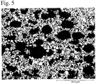
- the SEM photographs of cross sections of the linings of Examples 1 and 2, and Comparative Examples 1 and 2 are shown in Figs. 2-5 .
- black portions are the matrix regions composed of the Ni-based alloy 31
- white portions are the tungsten carbide particles 32
- gray portions adjacent to the tungsten carbide particles 32 are the boundary phases 33.
- the mechanical strength was evaluated by bending strength measured by a four-point bending test of each cut-out measurement sample having 0.1-C-chamfered longitudinal edges (thickness: 1.5 mm, width: 4.0 mm, and length: 40 mm), at an upper inter-fulcrum distance of 10 mm, a lower inter-fulcrum distance of 30 mm, and a test speed of 0.2 mm/min.
- a round rod test piece of 10 mm in diameter and 15 mm in length was cut out of an end portion of the HIPed composite cylinder, such that the lining layer existed in one end surface.
- the end surface having the lining layer was finished by grinding. While rotating this test piece around its center axis at 150 rpm, the lining-layer-existing end surface was pressed to a #1500 grinder paper at a load of 90 N for 3 minutes two times, and the wear weight of the test piece was measured. The wear weight was divided by a test surface area to determine the amount of wear.
- Test pieces (20 mm x 4 mm x 1.5 mm) were cut out of an end portion of the lining layer of the HIPed composite cylinder. These test pieces were immersed in an 18-% aqueous hydrochloric acid solution at 50°C and a 10-% aqueous nitric acid solution at 50°C each for 24 hours, to measure their weight loss by corrosion.
- a honing head having four diamond grinders (4 mm x 4 mm x 100 mm; and abrasive size: #100) circumferentially arranged at circumferential intervals of 90° was rotated at 100 rpm, and inserted into the HIPed composite cylinder from which the mandrel was removed by machining, such that it came into surface contact with the inner surface of the composite cylinder at an expansion pressure of 0.3 MPa.
- the honing head reciprocated longitudinally 10 times over the entire length of the cylinder to measure the amount of grinding the inner surface. Table 5 No.
- Comparative Example 1 contained 20% by volume of tungsten carbide particles having a median diameter of 14.6 ⁇ m, it exhibited extremely poorer mechanical strength (bending strength), wear resistance and machinability than those of Examples 1 and 2.
Landscapes
- Engineering & Computer Science (AREA)
- Mechanical Engineering (AREA)
- Manufacturing & Machinery (AREA)
- Chemical & Material Sciences (AREA)
- Materials Engineering (AREA)
- Metallurgy (AREA)
- Organic Chemistry (AREA)
- Chemical Kinetics & Catalysis (AREA)
- Composite Materials (AREA)
- Extrusion Moulding Of Plastics Or The Like (AREA)
- Injection Moulding Of Plastics Or The Like (AREA)
- Powder Metallurgy (AREA)
Abstract
Description
- The present invention relates to a molding machine cylinder having a composite structure comprising a lining layer having excellent wear resistance, corrosion resistance and machinability, which is mainly used in injection-molding or extrusion-molding machines for plastics.
- It is required that cylinders used for machines for injection-molding or extrusion-molding plastics, etc. withstand wear by resins, additives, etc. during high-temperature molding, and can be produced at lower cost. To meet such requirements, a molding machine cylinder having a bimetal structure comprising a lining layer having tungsten carbide particles dispersed in a nickel alloy matrix, which is formed by a centrifugal casting method on an inner surface of a steel-made circular cylinder, has conventionally been used.
- In recent extrusion or injection molding of reinforced plastics and flame-retardant plastics used in electronic or electric parts and automobile parts, molding machine cylinders are exposed to severe wear and corrosion. For example, because the reinforced plastics exert severe wear by their glass fibers or inorganic fillers, and the flame-retardant plastics exert severe corrosion by isolated halogens, development has been conducted to provide molding machine cylinders having lining layers formed by HIP.
-
JP H5-269813 A -
JP S61-218869 A JP S61-218869 A - However, even the molding machine cylinders having lining layers formed by HIP, which are described in
JP H5-269813 A JP S61-218869 A JP H5-269813 A - Accordingly, an object of the present invention is to provide a molding machine cylinder comprising a lining layer having excellent wear resistance, corrosion resistance and machinability and suffering no deterioration of mechanical strength even when the amount of tungsten carbide particles is increased, and its production method.
- In view of the above object, the inventors have conducted intensive research on a HIPed lining layer of a Ni-based alloy containing tungsten carbide particles, finding that when the structure of the lining layer is optimized, the lining layer can be provided with improved wear resistance and corrosion resistance as well as excellent machinability, without suffering the deterioration of mechanical strength even when the percentage of tungsten carbide particles is increased. The present invention has been completed based on such finding.
- Thus, the molding machine cylinder of the present invention comprises a HIP-sintered lining layer formed on an inner surface of a cylindrical steel body, the lining layer comprising 38-70% by volume of tungsten carbide particles having a median diameter d50 of 1-7 µm and a matrix composed of an Ni-based alloy, and the maximum length of the matrix in an arbitrary cross section being 12 µm or less.
- The tungsten carbide particles preferably have d10 of 0.5-3 µm and d90 of 5-15 µm, wherein d10 and d90 are particle sizes at cumulative volumes corresponding to 10% and 90%, respectively, of the total volume, in a curve expressing the relation between the particle size and cumulative volume (value obtained by accumulating the volume of particles having sizes up to a particular size) of tungsten carbide particles.
- The matrix composed of an Ni-based alloy preferably contains by mass 1-7% of Si, 5-20% of Cr, and 1-4% of B.
- The matrix composed of an Ni-based alloy preferably contains at least one of less than 0.13% of C, 1.5% or less of Mn, 12% or less of Co, 1% or less of Fe, and 0.1% or less of Mo.
- The lining layer preferably contains 45-60% by volume of the tungsten carbide particles.
- The method of the present invention for producing a cylinder for a molding machine comprises the steps of
arranging a steel mandrel inside a cylindrical steel body to form a space between an inner surface of the cylindrical body and the mandrel;
filling the space with a powdery mixture comprising tungsten carbide powder and Ni-based alloy powder at a volume ratio of 38/62 to 70/30;
evacuating and sealing the space containing the powdery mixture, and then subjecting the powdery mixture to HIP to obtain a composite cylinder whose cylindrical body is lined with the Ni-based alloy containing tungsten carbide particles; and
machining the resultant composite cylinder;
the tungsten carbide powder having a median diameter d50 of 1-7 µm, and d50/(d90 - d10) of 0.4 or more; and
the Ni-based alloy powder having a median diameter d50 of 2-8 µm, and d50/(d90 - d10) of 0.6 or more. - Because the molding machine cylinder of the present invention comprises a lining layer having excellent wear resistance, corrosion resistance and machinability and suffering no deterioration of mechanical strength even when the amount of tungsten carbide particles is increased, it is suitable for injection-molding or extrusion-molding machines for plastics.
-
-
Fig. 1 is a schematic cross-sectional view showing an example of the molding machine cylinders of the present invention. -
Fig. 2 is an electron photomicrograph showing a cross section of the lining layer of the molding machine cylinder of Example 1. -
Fig. 3 is an electron photomicrograph showing a cross section of the lining layer of the molding machine cylinder of Example 2. -
Fig. 4 is an electron photomicrograph showing a cross section of the lining layer of the molding machine cylinder of Comparative Example 1. -
Fig. 5 is an electron photomicrograph showing a cross section of the lining layer of the molding machine cylinder of Comparative Example 2. -
Fig. 6 is a schematic view for explaining a method for measuring the maximum length of a matrix in the lining layer. -
Fig. 7 is a schematic cross-sectional view showing a mandrel inserted into the cylindrical body. -
Fig. 8 is a schematic cross-sectional view showing alloy powder for the lining charged into a space between the cylindrical body and the mandrel. - As shown in
Fig. 1 , thecylinder 1 for a molding machine according to the present invention comprises a HIP-sintered lining layer, which is simply calledlining layer 3, on an inner surface of acylindrical steel body 2, thelining layer 3 comprising 38-70% by volume of tungsten carbide particles having a median diameter d50 of 1-7 µm and a matrix composed of an Ni-based alloy, and the maximum length of the matrix in an arbitrary cross section being 12 µm or less. Thelining layer 3 is formed by sintering a powdery mixture of Ni-based alloy powder and tungsten carbide powder by a HIP process, such that it is integrally fused to an inner surface of thecylindrical body 2. - As shown in
Fig. 4 , for example, thelining layer 3 obtained by HIP-sintering Ni-based alloy powder and tungsten carbide powder has a structure in which gaps between tungsten carbide particles (white portions) 32 are filled with a matrix composed of an Ni-based alloy 31 (black portions). In the figure, there are gray portions (boundary phases 33) adjacent to thetungsten carbide particles 32. Theboundary phases 33 having an intermediate composition between those of the Ni-basedalloy 31 and thetungsten carbide particles 32 are presumably formed by their reaction. Thelining layer 3 in the molding machine cylinder of the present invention should have a structure in which "the maximum length of the matrix" determined on a SEM photograph of its cross section by a method described below is 12 µm or less. When the maximum length of the matrix is more than 12 µm, as described above, thelining layer 3 has low mechanical strength as well as poor wear resistance and corrosion resistance. The maximum length of the matrix is preferably 10 µm or less, further preferably 8 µm or less, most preferably 6 µm or less. - As shown in
Fig. 6 , "the maximum length of the matrix" is determined by drawing two diagonal lines on a SEM photograph (field area: 127 µm x 94 µm) taken at a magnification of about 1000 times (acceleration voltage: 10.0 kV), measuring the lengths of line segments of each diagonal line crossing matrix regions composed of the Ni-basedalloy 31 with notungsten carbide particles 32 and noboundary phases 33, and averaging the maximum lengths in 10 fields. For example, inFig. 6 schematically showing the SEM photograph of Comparative Example 1, the longest line segment "a" among line segments "a" to "f" (only six long line segments are shown in the figure), in which two diagonal lines cross matrix regions, is selected, and the longest line segments in 10 fields are averaged to determine the maximum length of the matrix. - Comprising 38-70% by volume of tungsten carbide particles having a median diameter d50 of 1-7 µm and the matrix composed of the Ni-based alloy, with a structure in which "the maximum length of the matrix" is 12 µm or less, the lining layer of the present invention exhibits excellent wear resistance, corrosion resistance and machinability.
- Comprising 38-70% by volume of relatively small
tungsten carbide particles 32 having a median diameter d50 of 1-7 µm and the matrix composed of the Ni-basedalloy 31, thelining layer 3 has excellent machinability as well as improved wear resistance. - The percentage of the
tungsten carbide particles 32 is 38-70% by volume per the total amount of the Ni-basedalloy 31 and thetungsten carbide particles 32 constituting thelining layer 3. Less than 38% by volume oftungsten carbide particles 32 insufficiently improves the wear resistance, while more than 70% by volume oftungsten carbide particles 32 undesirably decreases the mechanical strength. The percentage of thetungsten carbide particles 32 is preferably 45% or more by volume, more preferably 50% or more by volume. Also, the percentage of thetungsten carbide particles 32 is preferably 65% or less by volume, more preferably 60% or less by volume. - The
tungsten carbide particles 32 has a median diameter d50 of 1-7 µm. Uniform dispersion is difficult when it is less than 1 µm, while the lining layer has poor machinability when it is more than 7 µm. The median diameter d50 of thetungsten carbide particles 32 is preferably 2 µm or more and 6 µm or less. Because the lining layer is densely filled with interconnected tungsten carbide particles, it is difficult to determine the sizes of WC particles on an electron photomicrograph. Accordingly, used herein as the median diameter d50 of thetungsten carbide particles 32 dispersed in the lining layer is that measured on tungsten carbide powder as a raw material by a Microtrac particle size distribution meter 9320-X100 available from Nikkiso Co., Ltd., for example. Because the lining layer in the molding machine cylinder of the present invention is sintered at a relatively low temperature (930-970°C) by HIP, the particle sizes of tungsten carbide powder as a raw material are substantially not different from those of the tungsten carbide particles in the lining layer. Accordingly, the median diameter d50 of the tungsten carbide particles dispersed in the lining layer may be expressed by the median diameter d50 of the tungsten carbide powder as a raw material. - The tungsten carbide particles preferably have d10 of 0.5-3 µm, and d90 of 5-15 µm, wherein d10 and d90 are particle sizes at cumulative volumes corresponding to 10% and 90%, respectively, of the total volume, in a curve expressing the relation between the particle size and cumulative volume (value obtained by accumulating the volume of particles having sizes up to a particular size) of tungsten carbide particles.
- The matrix composed of the Ni-based
alloy 31 constituting thelining layer 3 preferably comprises by mass 1-7% of Si, 5-20% of Cr, 1-4% of B, 1.5% or less of Mn, and 12% or less of Co as indispensable components, the balance being Ni and inevitable impurities. - Si is dissolved in the matrix composed of the Ni-based
alloy 31 in thelining layer 3 to increase its hardness, thereby contributing to improvement in wear resistance. Less than 1% by mass of Si does not sufficiently provide this effect, while more than 7% by mass of Si makes thelining layer 3 brittle. The Si content is more preferably 2% or more by mass, further preferably 2.5% or more by mass, most preferably 2.8% or more by mass. Also, the Si content is more preferably 4% or less by mass, further preferably 3.5% or less by mass, most preferably 3.2% or less by mass. - Cr is mainly dissolved in the matrix composed of the Ni-based
alloy 31 to increase the strength and corrosion resistance. Less than 5% by mass of Cr unlikely provides the effect of improving the strength and corrosion resistance, while more than 20% by mass of Cr reduces the toughness of the matrix. The Cr content is more preferably 5.5% or more by mass, further preferably 6.5% or more by mass. Also, the Cr content is more preferably 15% or less by mass, further preferably 10% or less by mass, most preferably 8.5% or less by mass. - B is combined with Ni, Cr, etc. to precipitate high-hardness borides in the structure, thereby improving the hardness of the matrix. Less than 1% by mass of B does not provide such effect sufficiently, while more than 4% by mass of B forms excessive borides, lowering the strength of the lining layer. The B content is more preferably 2% or more by mass, further preferably 2.5% or more by mass. Also, the B content is more preferably 3.7% or less by mass, further preferably 3.2% or less by mass.
- Mn removes undesirable substance such as oxides, etc. in the production of the Ni-based alloy by an atomizing method. More than 1.5% by mass of Mn undesirably deteriorates the corrosion resistance of the
lining layer 3. The Mn content is more preferably 0.5% or more by mass, further preferably 0.7% or more by mass. Also, the Mn content is more preferably 1.3% or less by mass, further preferably 1.2% or less by mass. - Like Ni, Co imparts corrosion resistance to the
lining layer 3, and is dissolved in the matrix to improve its strength. More than 12% by mass of Co is not economical because of the saturation of such effect. The Co content is more preferably 5% or more by mass, further preferably 8% or more by mass. Also, the Co content is more preferably 11.5% or less by mass, further preferably 11% or less by mass. - The inevitable impurities include C, Fe, etc. C is preferably 0.13% or less by mass, because more than 0.13% by mass of C provides brittleness and low strength to the lining layer. Fe is preferably 0.5% or less by mass, because more than 0.5% by mass of Fe provides low corrosion resistance.
- The cylindrical body is preferably formed by high-yield-strength steel, to hold the lining layer strongly and prevent the cracking of the lining layer during molding. Such high-yield-strength steel is preferably carbon steel or microalloyed steel, particularly microalloyed steel.
- The carbon steel per se may be known one, and, for example, carbon steel containing 0.25-0.6% by mass of C is preferable. The general composition of such carbon steel comprises 0.25-0.6% by mass of C, 0.15-0.35% by mass of Si, and 0.60-0.90% by mass of Mn, the balance being substantially Fe and inevitable impurities.
- Because the microalloyed steel containing alloying elements such as V, etc. has excellent yield strength and toughness without heat treatment (tempering), it can be formed into a composite cylinder at lower cost than steel such as S45C, SCM440, etc. (needing a heat treatment after HIP to obtain sufficient yield strength).
- The microalloyed steel for forming a cylindrical body generally has a composition comprising 0.3-0.6% by mass of C, 0.01-1% by mass of Si, 0.1-2% by mass of Mn, and 0.05-0.5% by mass of V, the balance being substantially Fe and inevitable impurities. The microalloyed steel may further contain as optional elements at least one selected from the group consisting of 0.01-1% by mass of Cr, 0.01-1% by mass of Cu, and 0.01-1% by mass of Nb.
- The method of the present invention for producing the molding machine cylinder comprises the steps of
- (a) arranging a steel mandrel inside a cylindrical steel body to form a space between an inner surface of the cylindrical body and the mandrel;
- (b) filling the space with a powdery mixture comprising tungsten carbide powder and Ni-based alloy powder at a volume ratio of 38/62 to 70/30;
- (c) evacuating and sealing the space containing the powdery mixture, and then subjecting the powdery mixture to HIP, to obtain a composite cylinder having a lining of the Ni-based alloy containing tungsten carbide particles on an inner surface of the cylindrical body (HIP process); and
- (d) machining the resultant composite cylinder;
the tungsten carbide powder having a median diameter d50 of 1-7 µm, and d50/(d90 - d10) of 0.4 or more; and
the Ni-based alloy powder having a median diameter d50 of 2-8 µm, and d50/(d90 - d10) of 0.6 or more. - The method of the present invention can produce a molding machine cylinder having a HIP-sintered lining layer on an inner surface of a cylindrical steel body, the sintered lining layer comprising 38-70% by volume of tungsten carbide particles having a median diameter d50 of 1-7 µm and the matrix composed of the Ni-based alloy, and the maximum length of the matrix in an arbitrary cross section being 12 µm or less.
- As shown in
Fig. 7 , thesteel mandrel 4 is placed inside thecylindrical steel body 2 to form anannular space 5 between thecylindrical body 2 and themandrel 4, in which thelining layer 3 of themolding machine cylinder 1 is molded. Alid 6 is welded to one-side ends of themandrel 4 and thecylindrical body 2. Themandrel 4 may be a solid or hollow cylinder. Themandrel 4 and thelids - The tungsten carbide powder and the Ni-based alloy powder are prepared. The tungsten carbide powder used has a median diameter d50 of 1-7 µm. When the median diameter is less than 1 µm, the uniform mixing of the tungsten carbide powder with the Ni-based alloy powder is difficult, and the material cost is high. When the median diameter is more than 7 µm, the resultant lining layer has poor machinability. The median diameter d50 of the tungsten carbide powder is preferably 2 µm or more and 6 µm or less. The tungsten carbide powder preferably has d10 of 0.5-3 µm and d90 of 5-15 µm. The tungsten carbide powder used has d50/(d90 - d10) of 0.4 or more. The value of d50/(d90 - d10) is an index indicating the particle size distribution. The d50/(d90 - d10) of 0.4 or more provides a sharp particle size distribution, resulting in a lining layer excellent in both wear resistance and machinability. The d50/(d90 - d10) of the tungsten carbide powder is preferably 0.5 or more, more preferably 0.6 or more.
- The Ni-based alloy powder used has a matrix composition comprising by mass 1-7% of Si, 5-20% of Cr, 1-4% of B, 1.5% or less of Mn, and 12% or less of Co as indispensable components, the balance being Ni and inevitable impurities, and a median diameter d50 of 2-8 µm. When the median diameter is less than 2 µm, its uniform mixing with the tungsten carbide powder is difficult, and the material cost is high. When the median diameter is more than 8 µm, the resultant lining layer has the maximum length of the matrix exceeding 12 µm, exhibiting poor wear resistance and corrosion resistance. The Ni-based alloy powder preferably has a median diameter d50 of 6 µm or less. The Ni-based alloy powder preferably has d10 of 1-5 µm and d90 of 6-12. The Ni-based alloy powder used has d50/(d90 - d10) of 0.6 or more. The value of d50/(d90 - d10) is an index indicating the particle size distribution. The d50/(d90 - d10) of 0.6 or more provides a sharp particle size distribution, leading to easy uniform mixing of the tungsten carbide powder having a sharp particle size distribution and the Ni-based alloy powder, thereby providing a lining layer having a structure in which the tungsten carbide particles are uniformly dispersed in the matrix composed of the Ni-based alloy. The d50/(d90 - d10) of the Ni-based alloy powder is preferably 0.8 or more, more preferably 0.9 or more.
- The Ni-based alloy powder is preferably produced by atomizing a molten Ni-based alloy. Because the atomized Ni-based alloy powder is substantially spherical, having good flowability, it can be uniformly mixed with the tungsten carbide powder. A gas atomizing method and a water atomizing method can be used for atomizing, and the water atomizing method is preferable.
- The d50 (median diameter), d10 and d90 of the tungsten carbide powder and the Ni-based alloy powder can be determined from their particle size distributions measured, for example, by a Microtrac particle size distribution meter 9320-X100 available from Nikkiso Co., Ltd. The d50 (median diameter), d10 and d90 are particle sizes at cumulative volumes corresponding to 50%, 10% and 90%, respectively, of the total volume, in a curve expressing the relation between the particle size and cumulative volume (value obtained by accumulating the volume of particles having sizes up to a particular size) of powder.
- After weighing the tungsten carbide powder and the Ni-based alloy powder to a volume ratio of 38/62 to 70/30 (38-70% by volume as a ratio of the tungsten carbide powder), they are dry-mixed. The weight of each powder is measured, and converted to a volume ratio using the specific gravities of the tungsten carbide and the Ni-based alloy. When the percentage of the tungsten carbide powder in the powdery mixture is less than 38% by volume, the lining layer has insufficient wear resistance. When it is more than 70% by volume, the lining layer has drastically reduced mechanical strength. The percentage of the tungsten carbide powder in the powdery mixture is preferably 45% or more by volume, more preferably 50% or more by volume. Also, the percentage of the tungsten carbide powder in the powdery mixture is preferably 65% or less by volume, more preferably 60% or less by volume.
- The resultant
powdery mixture 3a is charged into thespace 5. The charging of the alloy powder is preferably conducted while properly vibrating thecylindrical body 2. After thepowdery mixture 3a is charged, alid 7 having an evacuatingaperture 8 is welded to the other ends of thecylindrical body 2 and themandrel 4. - After the
space 5 containing thepowdery mixture 3a is evacuated, the evacuatingaperture 8 of thelid 7 is sealed by welding, and HIP is conducted by a known method. HIP is preferably conducted at 930-970°C and 100-150 MPa for 1-5 hours in an inert gas atmosphere such as Ar, etc. HIP produces a composite cylinder having a lining layer containing tungsten carbide particles in the matrix composed of the Ni-based alloy, which is integrally bonded to an inner surface of the cylindrical body. The lower limit of the HIP temperature is more preferably 940°C, most preferably 945°C. The upper limit is more preferably 960°C. - After successively removing the
lids mandrel 4 from the HIPed composite cylinder by cutting, etc., the inner surface of the cylinder is finished. If necessary, an aperture for a hopper for charging materials is formed in the cylinder. - Because the median diameters and particle size distributions of tungsten carbide powder and Ni-based alloy powder are controlled in the molding machine cylinder thus produced, the lining layer has a structure in which tungsten carbide particles are uniformly dispersed in the matrix composed of the Ni-based alloy, exhibiting high mechanical strength, as well as excellent wear resistance, corrosion resistance and machinability.
- The present invention will be explained in further detail by Examples, without intention of restricting the present invention thereto.
- Ni-based alloys A and C having the chemical compositions shown in Table 1-1 were prepared as alloy materials for forming lining layers, and each was atomized to produce Ni-based alloy powders A and C having d50 (median diameter), d10 and d90 shown in Table 1-2. The Ni-based alloy powder A was sieved to less than 25 µm to provide Ni-based alloy powder B. Also, two types of tungsten carbide powders A and B having d50 (median diameter), d10 and d90 shown in Table 2 were prepared.
Table 1-1 Ni-Based Alloy C Si Mn Cr Co Fe B Ni A 0.06 2.93 0.9 7.46 9.96 0.17 2.9 Bal. C 0.05 2.91 1 7.5 9.95 0.18 2.8 Bal. [0078] Note: The unit is % by mass. The Ni-based alloys A and C contained inevitable impurities. Table 1-2 Ni-Based Alloy Powder Median Diameter d50 d10 d90 d50/(d90 - d10) A 42.9 pin 16.2 µm 66.1 µm 0.86 B 14.2 µm 6.4 µm 19.8 µm 1.06 C 5 µm 2.7 µm 7.8 µm 0.98 Table 2 Tungsten Carbide Powder Median Diameter d50 d10 d90 d50/(d90 - d10) A 14.6 µm 7.7 µm 125.2 µm 0.12 B 4.1 µm 2.0 µm 8.2 µm 0.66 - As shown in
Fig. 7 , a solidcylindrical SUS304 mandrel 4 of 24 mm in outer diameter for forming alining layer 3 of amolding machine cylinder 1 was inserted into acylindrical body 2 of 120 mm in outer diameter, 36 mm in inner diameter and 840 mm in length, which was made of microalloyed steel having a composition comprising 0.48% by mass of C, 0.2% by mass of Si, 1.3% by mass of Mn, 0.02% by mass of P, 0.05% by mass of S, 0.2% by mass of Cr, and 0.2% by mass of V, the balance being Fe and inevitable impurities. Alid 6 made of the same material as that of themandrel 4 was welded to one-side ends of themandrel 4 and thecylindrical body 2, to form anannular space 5 between thecylindrical body 2 and themandrel 4. The materials and shapes of thecylindrical body 2 and themandrel 4 are shown in Table 3. - The Ni-based alloy powder C and the tungsten carbide powder B were obtained at a mass ratio corresponding to 60% by volume of the Ni-based alloy powder to 40% by volume of the tungsten carbide powder, using the specific gravities of 8 for the Ni-based alloy and 15.6 for the tungsten carbide in the conversion of the volume ratio to the mass ratio. These powders were dry-mixed by a mixer, and the resultant
powdery mixture 3a was charged into thespace 5. After thepowdery mixture 3a was charged, alid 7 having an evacuatingaperture 8 was welded to the other ends of thecylindrical body 2 and themandrel 4. Thespace 5 containing thepowdery mixture 3a was evacuated through the evacuatingaperture 8, and the evacuatingaperture 8 was sealed by welding. The sealed cylinder containing thepowdery mixture 3a was placed in a HIP apparatus to conduct HIP at 950°C and 132.7 MPa for 4 hours in an Ar gas atmosphere. After thelids mandrel 4 were successively removed from the HIPed composite cylinder by cutting, etc., the inner surface of the cylinder was finish-machined to obtain a molding machine cylinder (outer diameter: 90 mm, inner diameter: 28 mm, and length: 706 mm) having a 2.2-mm-thick lining layer of a Ni-based alloy containing tungsten carbide particles on the inner surface of the cylindrical body. The types and amounts of the Ni-based alloy powder and the tungsten carbide powder used and the shapes of the machined cylinders for molding machines are shown in Table 4. - A molding machine cylinder (outer diameter: 90 mm, inner diameter: 28 mm, and length: 706 mm) having a 2.1-mm-thick lining layer of a Ni-based alloy containing tungsten carbide particles on an inner surface of a cylindrical body was produced in the same manner as in Example 1, except for changing the types and amounts of the Ni-based alloy powder and the tungsten carbide powder as shown in Table 4.
- A molding machine cylinder (outer diameter: 90 mm, inner diameter: 32 mm, and length: 851 mm) having a 2.3-mm-thick lining layer of a Ni-based alloy containing tungsten carbide particles on an inner surface of a cylindrical body was produced in the same manner as in Example 1, except for changing the cylindrical body and the mandrel as shown in Table 3, and the types and amounts of the Ni-based alloy powder and the tungsten carbide powder as shown in Table 4.
- A molding machine cylinder (outer diameter: 94 mm, inner diameter: 32 mm, and length: 859 mm) having a 1.9-mm-thick lining layer of a Ni-based alloy containing tungsten carbide particles on an inner surface of a cylindrical body was produced in the same manner as in Example 1, except for changing the cylindrical body and the mandrel as shown in Table 3, the types and amounts of the Ni-based alloy powder and the tungsten carbide powder as shown in Table 4, and further the HIP time to 2 hours.
Table 3 No. Cylindrical Body Mandrel Material Outer Diameter Inner Diameter Length Material Outer Diameter Example 1 Microalloyed Steel 120 36 840 SUS304 24 Example 2 Microalloyed Steel 120 36 840 SUS304 24 Com. Ex. 1 Microalloyed Steel 100 40 890 SS400 28 Com. Ex. 2 Microalloyed Steel 100 40 920 SUS304 31 Table 4 No. Ni-Based Alloy Powder Tungsten Carbide Powder Shape of Cylinder for Molding Machine Type Vol. % Type Vol. % Outer Diameter (mm) Inner Diameter (mm) Length (mm) Thickness of Lining Layer (mm) Example 1 C 60 B 40 90 28 706 2.2 Example 2 C 45 B 55 90 28 706 2.1 Com. Ex. 1 A 80 A 20 90 32 851 2.3 Com. Ex. 2 B 60 B 40 94 32 859 1.9 - A measurement sample was cut out of an end portion of the lining layer of the HIPed composite cylinder, to evaluate the maximum length of the matrix, and the mechanical strength, wear resistance, corrosion resistance and machinability of the lining layer in the molding machine cylinder, by methods described below.
- Diagonal lines were drawn on a SEM photograph (field area: 127 µm x 94 µm) of a cross section of the lining layer taken at magnification of about 1000 times (acceleration voltage: 10.0 kV), and the lengths of line segments of each diagonal line crossing matrix regions composed of the Ni-based
alloy 31 with notungsten carbide particles 32 and no boundary phases 33 were measured, and the maximum lengths of the matrix in 10 fields were averaged (seeFig. 6 ). The SEM photographs of cross sections of the linings of Examples 1 and 2, and Comparative Examples 1 and 2 are shown inFigs. 2-5 . In the figures, black portions are the matrix regions composed of the Ni-basedalloy 31, white portions are thetungsten carbide particles 32, and gray portions adjacent to thetungsten carbide particles 32 are the boundary phases 33. - The mechanical strength was evaluated by bending strength measured by a four-point bending test of each cut-out measurement sample having 0.1-C-chamfered longitudinal edges (thickness: 1.5 mm, width: 4.0 mm, and length: 40 mm), at an upper inter-fulcrum distance of 10 mm, a lower inter-fulcrum distance of 30 mm, and a test speed of 0.2 mm/min.
- A round rod test piece of 10 mm in diameter and 15 mm in length was cut out of an end portion of the HIPed composite cylinder, such that the lining layer existed in one end surface. The end surface having the lining layer was finished by grinding. While rotating this test piece around its center axis at 150 rpm, the lining-layer-existing end surface was pressed to a #1500 grinder paper at a load of 90 N for 3 minutes two times, and the wear weight of the test piece was measured. The wear weight was divided by a test surface area to determine the amount of wear.
- Test pieces (20 mm x 4 mm x 1.5 mm) were cut out of an end portion of the lining layer of the HIPed composite cylinder. These test pieces were immersed in an 18-% aqueous hydrochloric acid solution at 50°C and a 10-% aqueous nitric acid solution at 50°C each for 24 hours, to measure their weight loss by corrosion.
- Using a vertical honing machine (FVG-1500SA available from Fuji Honing Industrial Co., Ltd.), a honing head having four diamond grinders (4 mm x 4 mm x 100 mm; and abrasive size: #100) circumferentially arranged at circumferential intervals of 90° was rotated at 100 rpm, and inserted into the HIPed composite cylinder from which the mandrel was removed by machining, such that it came into surface contact with the inner surface of the composite cylinder at an expansion pressure of 0.3 MPa. The honing head reciprocated longitudinally 10 times over the entire length of the cylinder to measure the amount of grinding the inner surface.
Table 5 No. Maximum Length of Matrix (µm) Bending Strength (MPa) Wear Resistance (1) (mg/cm2) Corrosion Resistance (2) (mg/cm2) Machinability(3) (mg) 18-% Hydrochloric Acid 10-% Nitric Acid Example 1 11.4 1015 2.5 43.4 174.0 0.04 Example 2 6.0 1009 0.8 28.0 93.5 0.03 Com. Ex. 1 58.9 683 15.5 33.7 178.6 0.007 Com. Ex. 2 22.8 - 4.5 21.5 150.6 0.04 Note: (1) The wear resistance is expressed by the amount of wear per area after the wear test.
(2) The corrosion resistance is expressed by weight loss by corrosion per area after immersion in each corrosion solution at 50°C for 24 hours.
(3) The machinability is expressed by the amount of wear after the honing test. - It is clear from Table 5 that the molding machine cylinders of Examples 1 and 2 each having a lining layer comprising 38-70% by volume of tungsten carbide particles having a median diameter d50 of 1-7 µm and the matrix composed of the Ni-based alloy, the maximum length of the matrix in an arbitrary cross section being 12 µm or less, had excellent mechanical strength (bending strength), wear resistance and corrosion resistance, as well as excellent machinability.
- Because the molding machine cylinder of Comparative Example 1 contained 20% by volume of tungsten carbide particles having a median diameter of 14.6 µm, it exhibited extremely poorer mechanical strength (bending strength), wear resistance and machinability than those of Examples 1 and 2.
- Though the molding machine cylinder of Comparative Example 2 met the requirement of the present invention of containing 40% by volume tungsten carbide particles having a median diameter of 4.1 µm, it failed to meet the requirement of the present invention in that the matrix had the maximum length of 19.9 µm, exhibiting poorer wear resistance than those of Examples 1 and 2.
- It was confirmed that a glass-fiber-containing polyamide resin was able to be molded by the molding machine cylinder of Example 2 without causing any troubles.
Claims (5)
- A cylinder for a molding machine comprising a HIP-sintered lining layer on an inner surface of a cylindrical steel body;
said lining layer comprising 38-70% by volume of tungsten carbide particles having a median diameter d50 of 1-7 µm and a matrix composed of an Ni-based alloy; and
the maximum length of said matrix in an arbitrary cross section being 12 µm or less. - The cylinder for a molding machine according to claim 1, wherein said tungsten carbide particles have d10 of 0.5-3 µm and d90 of 5-15 µm, wherein d10 and d90 are particle sizes at cumulative volumes corresponding to 10% and 90%, respectively, of the total volume, in a curve expressing the relation between the particle size and cumulative volume (value obtained by accumulating the volume of particles having sizes up to a particular size) of said tungsten carbide particles.
- The cylinder for a molding machine according to claim 1 or 2, wherein said matrix composed of an Ni-based alloy comprises by mass 1-7% of Si, 5-20% of Cr, 1-4% of B, 1.5% or less of Mn, 12% or less of Co, and inevitable impurities.
- The cylinder for a molding machine according to any one of claims 1-3, wherein said lining layer contains 45-60% by volume of said tungsten carbide particles.
- A method for producing the cylinder for a molding machine recited in any one of claims 1-4, comprising the steps of
arranging a steel mandrel inside a cylindrical steel body to form a space between an inner surface of said cylindrical body and said mandrel;
filling said space with a powdery mixture comprising tungsten carbide powder and Ni-based alloy powder at a volume ratio of 38/62 to 70/30;
evacuating and sealing said space containing said powdery mixture, and then subjecting said powdery mixture to HIP to obtain a composite cylinder whose cylindrical body is lined with a Ni-based alloy containing tungsten carbide particles; and
machining said composite cylinder;
said tungsten carbide powder having a median diameter d50 of 1-7 µm, and d50/(d90 - d10) of 0.4 or more; and
said Ni-based alloy powder having a median diameter d50 of 2-8 µm, and d50/(d90 - d10) of 0.6 or more.
Applications Claiming Priority (2)
| Application Number | Priority Date | Filing Date | Title |
|---|---|---|---|
| JP2017167605 | 2017-08-31 | ||
| PCT/JP2018/032458 WO2019045067A1 (en) | 2017-08-31 | 2018-08-31 | Molding-machine cylinder and method for producing same |
Publications (3)
| Publication Number | Publication Date |
|---|---|
| EP3677402A1 true EP3677402A1 (en) | 2020-07-08 |
| EP3677402A4 EP3677402A4 (en) | 2021-06-02 |
| EP3677402B1 EP3677402B1 (en) | 2024-09-25 |
Family
ID=65525633
Family Applications (1)
| Application Number | Title | Priority Date | Filing Date |
|---|---|---|---|
| EP18852688.3A Active EP3677402B1 (en) | 2017-08-31 | 2018-08-31 | Cylinder for molding machine, and its production method |
Country Status (5)
| Country | Link |
|---|---|
| US (1) | US11389869B2 (en) |
| EP (1) | EP3677402B1 (en) |
| JP (1) | JP7099465B2 (en) |
| FI (1) | FI3677402T3 (en) |
| WO (1) | WO2019045067A1 (en) |
Cited By (1)
| Publication number | Priority date | Publication date | Assignee | Title |
|---|---|---|---|---|
| CN114786942A (en) * | 2019-08-06 | 2022-07-22 | 保特利尖端材料股份有限公司 | Aluminum pouch-shaped film for secondary battery and method for producing the same |
Family Cites Families (13)
| Publication number | Priority date | Publication date | Assignee | Title |
|---|---|---|---|---|
| JPS61218869A (en) | 1985-03-22 | 1986-09-29 | Kubota Ltd | Construction and manufacture for cylinder with high resistance to abrasion and erosion |
| JPS62273820A (en) | 1986-05-22 | 1987-11-27 | Kobe Steel Ltd | Composite cylinder for plastic molding apparatus |
| US4863661A (en) * | 1986-08-25 | 1989-09-05 | Xaloy, Inc. | Resin molding process employing a mickel-based alloy liner |
| JP3301442B2 (en) | 1992-03-26 | 2002-07-15 | 日立金属株式会社 | Composite cylinder for high-temperature and high-pressure molding |
| JPH06238725A (en) * | 1993-02-22 | 1994-08-30 | Japan Steel Works Ltd:The | Composite hollow member having optimized material at each position and manufacture of the same |
| JP2872571B2 (en) * | 1994-04-27 | 1999-03-17 | 株式会社日本製鋼所 | Tungsten carbide composite lining material for centrifugal casting and tungsten carbide composite lining layer |
| US5816699A (en) * | 1997-06-13 | 1998-10-06 | Entek Manufacturing Inc. | Twin screw extruder barrel with an easily removable seamless insert having a wear and corrosion resistant lining |
| JP2002161319A (en) * | 2000-11-17 | 2002-06-04 | Hitachi Metals Ltd | Cylinder for molding machine |
| JP4900806B2 (en) * | 2007-02-22 | 2012-03-21 | 日立金属株式会社 | Cylinder for molding machine |
| JP5267912B2 (en) * | 2008-04-18 | 2013-08-21 | 日立金属株式会社 | Plunger for molding machine |
| EP2740553A1 (en) * | 2012-12-07 | 2014-06-11 | Sandvik Intellectual Property AB | Method for manufacture of HIP consolidated component |
| US20150114720A1 (en) * | 2013-10-24 | 2015-04-30 | Smith International, Inc. | Inhibition of Microfissure Formation in Wear Resistant Coatings |
| JP6230156B2 (en) * | 2014-09-22 | 2017-11-15 | 株式会社日本製鋼所 | Lining material and cylinder for molding machine having the same |
-
2018
- 2018-08-31 US US16/632,670 patent/US11389869B2/en active Active
- 2018-08-31 JP JP2019539680A patent/JP7099465B2/en active Active
- 2018-08-31 FI FIEP18852688.3T patent/FI3677402T3/en active
- 2018-08-31 WO PCT/JP2018/032458 patent/WO2019045067A1/en not_active Ceased
- 2018-08-31 EP EP18852688.3A patent/EP3677402B1/en active Active
Cited By (1)
| Publication number | Priority date | Publication date | Assignee | Title |
|---|---|---|---|---|
| CN114786942A (en) * | 2019-08-06 | 2022-07-22 | 保特利尖端材料股份有限公司 | Aluminum pouch-shaped film for secondary battery and method for producing the same |
Also Published As
| Publication number | Publication date |
|---|---|
| US11389869B2 (en) | 2022-07-19 |
| EP3677402B1 (en) | 2024-09-25 |
| WO2019045067A1 (en) | 2019-03-07 |
| FI3677402T3 (en) | 2024-12-18 |
| EP3677402A4 (en) | 2021-06-02 |
| JPWO2019045067A1 (en) | 2020-11-12 |
| US20200222980A1 (en) | 2020-07-16 |
| JP7099465B2 (en) | 2022-07-12 |
Similar Documents
| Publication | Publication Date | Title |
|---|---|---|
| CN101772389B (en) | Iron-containing mixed powder for powder metallurgy and sintered iron powder compact | |
| EP1649953A2 (en) | Iron-based mixed powder for powder metallurgy and sintered body | |
| EP3738695A1 (en) | Stainless steel powder for molding | |
| CN107427913A (en) | Polycrystalline tungsten and tungsten alloy sintered body and manufacturing method thereof | |
| CN106756240B (en) | A kind of tungstenic 3D printing titanium-based alloy material and preparation method thereof | |
| US5470372A (en) | Sintered extremely fine-grained titanium-based carbonitride alloy with improved toughness and/or wear resistance | |
| EP4261302A1 (en) | Shaped body formed of powder | |
| JPH07290186A (en) | Tungsten carbide composite lining material for centrifugal casting and tungsten carbide composite lining layer | |
| JP6922110B1 (en) | Crushing / stirring / mixing / kneading machine parts | |
| EP3677402B1 (en) | Cylinder for molding machine, and its production method | |
| JP7848608B2 (en) | Fe-based alloys and metal powders for molten solidification molding | |
| US20140245863A1 (en) | Corrosion-resistant and wear-resistant ni-based alloy | |
| EP4163409B1 (en) | Wear-resistant member | |
| JP5095669B2 (en) | Cylinder lining material for centrifugal casting and centrifugal casting method for producing cylinder lining material | |
| EP1820868A1 (en) | Alloy with high hardness, high corrosion resistance and high abrasion resistance | |
| EP1582603B1 (en) | Iron base sintered alloy, iron base sintered alloy member, method for production thereof, and oil pump rotor | |
| JP3301441B2 (en) | Composite cylinder for high-temperature and high-pressure molding | |
| CN118389955A (en) | Iron-based laser cladding powder and preparation method thereof | |
| CN111432958A (en) | Partially diffused alloyed steel powder | |
| JPS62273820A (en) | Composite cylinder for plastic molding apparatus | |
| EP3978165A1 (en) | Iron-based alloy sintered body and iron-based mixed powder for powder metallurgy | |
| JP3563937B2 (en) | High corrosion resistant carbide dispersion material | |
| CN111394635B (en) | Nonmagnetic hard alloy for instrument shaft and preparation method thereof | |
| JP4121694B2 (en) | Sintered body Ni-based cermet and parts for plastic molding machine and die casting machine using the same | |
| US20240253267A1 (en) | Bimodal cemented carbide powders for additive manufacturing and structured bodies made therefrom |
Legal Events
| Date | Code | Title | Description |
|---|---|---|---|
| STAA | Information on the status of an ep patent application or granted ep patent |
Free format text: STATUS: THE INTERNATIONAL PUBLICATION HAS BEEN MADE |
|
| PUAI | Public reference made under article 153(3) epc to a published international application that has entered the european phase |
Free format text: ORIGINAL CODE: 0009012 |
|
| STAA | Information on the status of an ep patent application or granted ep patent |
Free format text: STATUS: REQUEST FOR EXAMINATION WAS MADE |
|
| 17P | Request for examination filed |
Effective date: 20200219 |
|
| AK | Designated contracting states |
Kind code of ref document: A1 Designated state(s): AL AT BE BG CH CY CZ DE DK EE ES FI FR GB GR HR HU IE IS IT LI LT LU LV MC MK MT NL NO PL PT RO RS SE SI SK SM TR |
|
| AX | Request for extension of the european patent |
Extension state: BA ME |
|
| DAV | Request for validation of the european patent (deleted) | ||
| DAX | Request for extension of the european patent (deleted) | ||
| A4 | Supplementary search report drawn up and despatched |
Effective date: 20210503 |
|
| RIC1 | Information provided on ipc code assigned before grant |
Ipc: B29C 48/68 20190101AFI20210426BHEP Ipc: B29C 45/62 20060101ALI20210426BHEP Ipc: B29C 33/38 20060101ALI20210426BHEP Ipc: B22F 3/00 20210101ALI20210426BHEP Ipc: B22F 5/10 20060101ALI20210426BHEP Ipc: B22F 7/08 20060101ALI20210426BHEP Ipc: C22C 29/06 20060101ALI20210426BHEP Ipc: C22C 29/08 20060101ALI20210426BHEP Ipc: C23C 24/10 20060101ALI20210426BHEP |
|
| RAP3 | Party data changed (applicant data changed or rights of an application transferred) |
Owner name: PROTERIAL, LTD. |
|
| GRAP | Despatch of communication of intention to grant a patent |
Free format text: ORIGINAL CODE: EPIDOSNIGR1 |
|
| STAA | Information on the status of an ep patent application or granted ep patent |
Free format text: STATUS: GRANT OF PATENT IS INTENDED |
|
| RIC1 | Information provided on ipc code assigned before grant |
Ipc: C23C 24/08 20060101ALI20240415BHEP Ipc: C23C 24/10 20060101ALI20240415BHEP Ipc: C22C 29/08 20060101ALI20240415BHEP Ipc: C22C 29/06 20060101ALI20240415BHEP Ipc: B22F 7/08 20060101ALI20240415BHEP Ipc: B22F 5/10 20060101ALI20240415BHEP Ipc: B22F 3/00 20060101ALI20240415BHEP Ipc: B29C 33/38 20060101ALI20240415BHEP Ipc: B29C 45/62 20060101ALI20240415BHEP Ipc: B29C 48/68 20190101AFI20240415BHEP |
|
| INTG | Intention to grant announced |
Effective date: 20240430 |
|
| RIN1 | Information on inventor provided before grant (corrected) |
Inventor name: FURUSHIMA, KIYOSHI Inventor name: SEGAWA, TAKAYUKI |
|
| GRAS | Grant fee paid |
Free format text: ORIGINAL CODE: EPIDOSNIGR3 |
|
| GRAA | (expected) grant |
Free format text: ORIGINAL CODE: 0009210 |
|
| STAA | Information on the status of an ep patent application or granted ep patent |
Free format text: STATUS: THE PATENT HAS BEEN GRANTED |
|
| P01 | Opt-out of the competence of the unified patent court (upc) registered |
Free format text: CASE NUMBER: APP_46867/2024 Effective date: 20240813 |
|
| AK | Designated contracting states |
Kind code of ref document: B1 Designated state(s): AL AT BE BG CH CY CZ DE DK EE ES FI FR GB GR HR HU IE IS IT LI LT LU LV MC MK MT NL NO PL PT RO RS SE SI SK SM TR |
|
| REG | Reference to a national code |
Ref country code: GB Ref legal event code: FG4D |
|
| REG | Reference to a national code |
Ref country code: CH Ref legal event code: EP |
|
| REG | Reference to a national code |
Ref country code: DE Ref legal event code: R096 Ref document number: 602018074790 Country of ref document: DE |
|
| REG | Reference to a national code |
Ref country code: IE Ref legal event code: FG4D |
|
| REG | Reference to a national code |
Ref country code: FI Ref legal event code: FGE |
|
| REG | Reference to a national code |
Ref country code: LT Ref legal event code: MG9D |
|
| PG25 | Lapsed in a contracting state [announced via postgrant information from national office to epo] |
Ref country code: NO Free format text: LAPSE BECAUSE OF FAILURE TO SUBMIT A TRANSLATION OF THE DESCRIPTION OR TO PAY THE FEE WITHIN THE PRESCRIBED TIME-LIMIT Effective date: 20241225 |
|
| PG25 | Lapsed in a contracting state [announced via postgrant information from national office to epo] |
Ref country code: GR Free format text: LAPSE BECAUSE OF FAILURE TO SUBMIT A TRANSLATION OF THE DESCRIPTION OR TO PAY THE FEE WITHIN THE PRESCRIBED TIME-LIMIT Effective date: 20241226 |
|
| PG25 | Lapsed in a contracting state [announced via postgrant information from national office to epo] |
Ref country code: BG Free format text: LAPSE BECAUSE OF FAILURE TO SUBMIT A TRANSLATION OF THE DESCRIPTION OR TO PAY THE FEE WITHIN THE PRESCRIBED TIME-LIMIT Effective date: 20240925 |
|
| PG25 | Lapsed in a contracting state [announced via postgrant information from national office to epo] |
Ref country code: LV Free format text: LAPSE BECAUSE OF FAILURE TO SUBMIT A TRANSLATION OF THE DESCRIPTION OR TO PAY THE FEE WITHIN THE PRESCRIBED TIME-LIMIT Effective date: 20240925 |
|
| PG25 | Lapsed in a contracting state [announced via postgrant information from national office to epo] |
Ref country code: RS Free format text: LAPSE BECAUSE OF FAILURE TO SUBMIT A TRANSLATION OF THE DESCRIPTION OR TO PAY THE FEE WITHIN THE PRESCRIBED TIME-LIMIT Effective date: 20241225 |
|
| REG | Reference to a national code |
Ref country code: NL Ref legal event code: MP Effective date: 20240925 |
|
| PG25 | Lapsed in a contracting state [announced via postgrant information from national office to epo] |
Ref country code: RS Free format text: LAPSE BECAUSE OF FAILURE TO SUBMIT A TRANSLATION OF THE DESCRIPTION OR TO PAY THE FEE WITHIN THE PRESCRIBED TIME-LIMIT Effective date: 20241225 Ref country code: NO Free format text: LAPSE BECAUSE OF FAILURE TO SUBMIT A TRANSLATION OF THE DESCRIPTION OR TO PAY THE FEE WITHIN THE PRESCRIBED TIME-LIMIT Effective date: 20241225 Ref country code: LV Free format text: LAPSE BECAUSE OF FAILURE TO SUBMIT A TRANSLATION OF THE DESCRIPTION OR TO PAY THE FEE WITHIN THE PRESCRIBED TIME-LIMIT Effective date: 20240925 Ref country code: GR Free format text: LAPSE BECAUSE OF FAILURE TO SUBMIT A TRANSLATION OF THE DESCRIPTION OR TO PAY THE FEE WITHIN THE PRESCRIBED TIME-LIMIT Effective date: 20241226 Ref country code: BG Free format text: LAPSE BECAUSE OF FAILURE TO SUBMIT A TRANSLATION OF THE DESCRIPTION OR TO PAY THE FEE WITHIN THE PRESCRIBED TIME-LIMIT Effective date: 20240925 |
|
| REG | Reference to a national code |
Ref country code: AT Ref legal event code: MK05 Ref document number: 1726309 Country of ref document: AT Kind code of ref document: T Effective date: 20240925 |
|
| PG25 | Lapsed in a contracting state [announced via postgrant information from national office to epo] |
Ref country code: NL Free format text: LAPSE BECAUSE OF FAILURE TO SUBMIT A TRANSLATION OF THE DESCRIPTION OR TO PAY THE FEE WITHIN THE PRESCRIBED TIME-LIMIT Effective date: 20240925 |
|
| PG25 | Lapsed in a contracting state [announced via postgrant information from national office to epo] |
Ref country code: IS Free format text: LAPSE BECAUSE OF FAILURE TO SUBMIT A TRANSLATION OF THE DESCRIPTION OR TO PAY THE FEE WITHIN THE PRESCRIBED TIME-LIMIT Effective date: 20250125 Ref country code: PT Free format text: LAPSE BECAUSE OF FAILURE TO SUBMIT A TRANSLATION OF THE DESCRIPTION OR TO PAY THE FEE WITHIN THE PRESCRIBED TIME-LIMIT Effective date: 20250127 |
|
| PG25 | Lapsed in a contracting state [announced via postgrant information from national office to epo] |
Ref country code: RO Free format text: LAPSE BECAUSE OF FAILURE TO SUBMIT A TRANSLATION OF THE DESCRIPTION OR TO PAY THE FEE WITHIN THE PRESCRIBED TIME-LIMIT Effective date: 20240925 Ref country code: SM Free format text: LAPSE BECAUSE OF FAILURE TO SUBMIT A TRANSLATION OF THE DESCRIPTION OR TO PAY THE FEE WITHIN THE PRESCRIBED TIME-LIMIT Effective date: 20240925 |
|
| PG25 | Lapsed in a contracting state [announced via postgrant information from national office to epo] |
Ref country code: ES Free format text: LAPSE BECAUSE OF FAILURE TO SUBMIT A TRANSLATION OF THE DESCRIPTION OR TO PAY THE FEE WITHIN THE PRESCRIBED TIME-LIMIT Effective date: 20240925 |
|
| PG25 | Lapsed in a contracting state [announced via postgrant information from national office to epo] |
Ref country code: EE Free format text: LAPSE BECAUSE OF FAILURE TO SUBMIT A TRANSLATION OF THE DESCRIPTION OR TO PAY THE FEE WITHIN THE PRESCRIBED TIME-LIMIT Effective date: 20240925 Ref country code: AT Free format text: LAPSE BECAUSE OF FAILURE TO SUBMIT A TRANSLATION OF THE DESCRIPTION OR TO PAY THE FEE WITHIN THE PRESCRIBED TIME-LIMIT Effective date: 20240925 |
|
| PG25 | Lapsed in a contracting state [announced via postgrant information from national office to epo] |
Ref country code: CZ Free format text: LAPSE BECAUSE OF FAILURE TO SUBMIT A TRANSLATION OF THE DESCRIPTION OR TO PAY THE FEE WITHIN THE PRESCRIBED TIME-LIMIT Effective date: 20240925 Ref country code: PL Free format text: LAPSE BECAUSE OF FAILURE TO SUBMIT A TRANSLATION OF THE DESCRIPTION OR TO PAY THE FEE WITHIN THE PRESCRIBED TIME-LIMIT Effective date: 20240925 |
|
| PG25 | Lapsed in a contracting state [announced via postgrant information from national office to epo] |
Ref country code: IT Free format text: LAPSE BECAUSE OF FAILURE TO SUBMIT A TRANSLATION OF THE DESCRIPTION OR TO PAY THE FEE WITHIN THE PRESCRIBED TIME-LIMIT Effective date: 20240925 Ref country code: SK Free format text: LAPSE BECAUSE OF FAILURE TO SUBMIT A TRANSLATION OF THE DESCRIPTION OR TO PAY THE FEE WITHIN THE PRESCRIBED TIME-LIMIT Effective date: 20240925 |
|
| REG | Reference to a national code |
Ref country code: DE Ref legal event code: R097 Ref document number: 602018074790 Country of ref document: DE |
|
| PG25 | Lapsed in a contracting state [announced via postgrant information from national office to epo] |
Ref country code: DK Free format text: LAPSE BECAUSE OF FAILURE TO SUBMIT A TRANSLATION OF THE DESCRIPTION OR TO PAY THE FEE WITHIN THE PRESCRIBED TIME-LIMIT Effective date: 20240925 |
|
| PLBE | No opposition filed within time limit |
Free format text: ORIGINAL CODE: 0009261 |
|
| STAA | Information on the status of an ep patent application or granted ep patent |
Free format text: STATUS: NO OPPOSITION FILED WITHIN TIME LIMIT |
|
| 26N | No opposition filed |
Effective date: 20250626 |
|
| PG25 | Lapsed in a contracting state [announced via postgrant information from national office to epo] |
Ref country code: SE Free format text: LAPSE BECAUSE OF FAILURE TO SUBMIT A TRANSLATION OF THE DESCRIPTION OR TO PAY THE FEE WITHIN THE PRESCRIBED TIME-LIMIT Effective date: 20240925 |
|
| PGFP | Annual fee paid to national office [announced via postgrant information from national office to epo] |
Ref country code: FI Payment date: 20250814 Year of fee payment: 8 |
|
| PGFP | Annual fee paid to national office [announced via postgrant information from national office to epo] |
Ref country code: DE Payment date: 20250702 Year of fee payment: 8 |
|
| PG25 | Lapsed in a contracting state [announced via postgrant information from national office to epo] |
Ref country code: HR Free format text: LAPSE BECAUSE OF FAILURE TO SUBMIT A TRANSLATION OF THE DESCRIPTION OR TO PAY THE FEE WITHIN THE PRESCRIBED TIME-LIMIT Effective date: 20240925 |
|
| REG | Reference to a national code |
Ref country code: CH Ref legal event code: H13 Free format text: ST27 STATUS EVENT CODE: U-0-0-H10-H13 (AS PROVIDED BY THE NATIONAL OFFICE) Effective date: 20260324 |
|
| PG25 | Lapsed in a contracting state [announced via postgrant information from national office to epo] |
Ref country code: MC Free format text: LAPSE BECAUSE OF FAILURE TO SUBMIT A TRANSLATION OF THE DESCRIPTION OR TO PAY THE FEE WITHIN THE PRESCRIBED TIME-LIMIT Effective date: 20240925 |
|
| PG25 | Lapsed in a contracting state [announced via postgrant information from national office to epo] |
Ref country code: LU Free format text: LAPSE BECAUSE OF NON-PAYMENT OF DUE FEES Effective date: 20250831 |
|
| PG25 | Lapsed in a contracting state [announced via postgrant information from national office to epo] |
Ref country code: CH Free format text: LAPSE BECAUSE OF NON-PAYMENT OF DUE FEES Effective date: 20250831 |
|
| GBPC | Gb: european patent ceased through non-payment of renewal fee |
Effective date: 20250831 |
|
| REG | Reference to a national code |
Ref country code: BE Ref legal event code: MM Effective date: 20250831 |
|
| PG25 | Lapsed in a contracting state [announced via postgrant information from national office to epo] |
Ref country code: LT Free format text: LAPSE BECAUSE OF FAILURE TO SUBMIT A TRANSLATION OF THE DESCRIPTION OR TO PAY THE FEE WITHIN THE PRESCRIBED TIME-LIMIT Effective date: 20240925 |
|
| PG25 | Lapsed in a contracting state [announced via postgrant information from national office to epo] |
Ref country code: GB Free format text: LAPSE BECAUSE OF NON-PAYMENT OF DUE FEES Effective date: 20250831 |
|
| PG25 | Lapsed in a contracting state [announced via postgrant information from national office to epo] |
Ref country code: BE Free format text: LAPSE BECAUSE OF NON-PAYMENT OF DUE FEES Effective date: 20250831 Ref country code: IE Free format text: LAPSE BECAUSE OF NON-PAYMENT OF DUE FEES Effective date: 20250831 |
|
| PG25 | Lapsed in a contracting state [announced via postgrant information from national office to epo] |
Ref country code: FR Free format text: LAPSE BECAUSE OF NON-PAYMENT OF DUE FEES Effective date: 20250831 |