EP3677386B1 - Assembly with a hand-held tool and with a support device and hand-held tool - Google Patents
Assembly with a hand-held tool and with a support device and hand-held tool Download PDFInfo
- Publication number
- EP3677386B1 EP3677386B1 EP20155766.7A EP20155766A EP3677386B1 EP 3677386 B1 EP3677386 B1 EP 3677386B1 EP 20155766 A EP20155766 A EP 20155766A EP 3677386 B1 EP3677386 B1 EP 3677386B1
- Authority
- EP
- European Patent Office
- Prior art keywords
- fastening point
- blower
- work apparatus
- arrangement according
- arrangement
- Prior art date
- Legal status (The legal status is an assumption and is not a legal conclusion. Google has not performed a legal analysis and makes no representation as to the accuracy of the status listed.)
- Active
Links
Images


Classifications
-
- E—FIXED CONSTRUCTIONS
- E01—CONSTRUCTION OF ROADS, RAILWAYS, OR BRIDGES
- E01H—STREET CLEANING; CLEANING OF PERMANENT WAYS; CLEANING BEACHES; DISPERSING OR PREVENTING FOG IN GENERAL CLEANING STREET OR RAILWAY FURNITURE OR TUNNEL WALLS
- E01H1/00—Removing undesirable matter from roads or like surfaces, with or without moistening of the surface
- E01H1/08—Pneumatically dislodging or taking-up undesirable matter or small objects; Drying by heat only or by streams of gas; Cleaning by projecting abrasive particles
- E01H1/0809—Loosening or dislodging by blowing ; Drying by means of gas streams
-
- B—PERFORMING OPERATIONS; TRANSPORTING
- B25—HAND TOOLS; PORTABLE POWER-DRIVEN TOOLS; MANIPULATORS
- B25F—COMBINATION OR MULTI-PURPOSE TOOLS NOT OTHERWISE PROVIDED FOR; DETAILS OR COMPONENTS OF PORTABLE POWER-DRIVEN TOOLS NOT PARTICULARLY RELATED TO THE OPERATIONS PERFORMED AND NOT OTHERWISE PROVIDED FOR
- B25F5/00—Details or components of portable power-driven tools not particularly related to the operations performed and not otherwise provided for
-
- A—HUMAN NECESSITIES
- A01—AGRICULTURE; FORESTRY; ANIMAL HUSBANDRY; HUNTING; TRAPPING; FISHING
- A01G—HORTICULTURE; CULTIVATION OF VEGETABLES, FLOWERS, RICE, FRUIT, VINES, HOPS OR SEAWEED; FORESTRY; WATERING
- A01G20/00—Cultivation of turf, lawn or the like; Apparatus or methods therefor
- A01G20/40—Apparatus for cleaning the lawn or grass surface
- A01G20/43—Apparatus for cleaning the lawn or grass surface for sweeping, collecting or disintegrating lawn debris
- A01G20/47—Vacuum or blower devices
-
- B—PERFORMING OPERATIONS; TRANSPORTING
- B25—HAND TOOLS; PORTABLE POWER-DRIVEN TOOLS; MANIPULATORS
- B25F—COMBINATION OR MULTI-PURPOSE TOOLS NOT OTHERWISE PROVIDED FOR; DETAILS OR COMPONENTS OF PORTABLE POWER-DRIVEN TOOLS NOT PARTICULARLY RELATED TO THE OPERATIONS PERFORMED AND NOT OTHERWISE PROVIDED FOR
- B25F5/00—Details or components of portable power-driven tools not particularly related to the operations performed and not otherwise provided for
- B25F5/02—Construction of casings, bodies or handles
-
- F—MECHANICAL ENGINEERING; LIGHTING; HEATING; WEAPONS; BLASTING
- F04—POSITIVE - DISPLACEMENT MACHINES FOR LIQUIDS; PUMPS FOR LIQUIDS OR ELASTIC FLUIDS
- F04D—NON-POSITIVE-DISPLACEMENT PUMPS
- F04D25/00—Pumping installations or systems
- F04D25/02—Units comprising pumps and their driving means
- F04D25/08—Units comprising pumps and their driving means the working fluid being air, e.g. for ventilation
-
- F—MECHANICAL ENGINEERING; LIGHTING; HEATING; WEAPONS; BLASTING
- F04—POSITIVE - DISPLACEMENT MACHINES FOR LIQUIDS; PUMPS FOR LIQUIDS OR ELASTIC FLUIDS
- F04D—NON-POSITIVE-DISPLACEMENT PUMPS
- F04D29/00—Details, component parts, or accessories
- F04D29/002—Details, component parts, or accessories especially adapted for elastic fluid pumps
Definitions
- the invention relates to an arrangement with a hand-held tool and a support device of the type specified in the preamble of claim 1.
- a hand-held tool namely a brush cutter
- the brush cutter has a hook which is intended to be attached to the belt arrangement.
- the hook forms a flexible connection with the eyelet, via which the weight of the implement can be absorbed.
- the implement is supported on the side of the support plate of the belt arrangement.
- the US 2012/131762 A1 , the US 2014/291362 A1 and the EP 1 740 070 A1 show carrying straps for transporting work equipment.
- the invention is based on the object of creating an arrangement with a hand-held implement and a support device which enables ergonomic and energy-saving work with the implement.
- the arrangement has a support device for supporting the implement during operation.
- a connecting device is provided which is held at a first fastening point on a holder to be carried by the operator and at a second fastening point on the working device.
- the connecting device is mounted pivotably about at least one pivot axis. It is provided that the center of gravity of the working device and the first fastening point in the working position of the working device are at a distance from one another, measured horizontally and laterally in relation to the operator. The first fastening point is accordingly next to the center of gravity of the working device in relation to the operator.
- the holder has means for at least partial support of the tilting moment which the weight of the implement exerts at the first fastening point due to the lateral distance. Accordingly, not only the weight force is absorbed via the holder, but also the tilting moment generated by the weight force at the first fastening point. The tilting moment is not recorded on a holding plate or the like on which the implement is supported, but on the first fastening point itself. Because the tilting moment is at least partially absorbed by the bracket at the first fastening point, this tilting moment must be at most during operation partially be recorded by the operator. As a result, the tool can be operated with little effort, so that fatigue-free operation is possible.
- the lateral distance between the center of gravity and the first fastening point is advantageously from about 5 cm to about 15 cm, in particular from about 7 cm to about 11 cm. A distance of about 10 cm has proven to be particularly advantageous.
- the implement can hang largely freely at the first fastening point without coming into contact with the operator from the side.
- the tilting moment to be absorbed by the holder is comparatively small, so that a simple construction of the holder is possible.
- the position of the second fastening point is adjustable.
- the length, the shape and / or the alignment of the connecting device can advantageously be adjusted.
- a structurally fixed predetermined position of the second fastening point relative to the first fastening point can also be advantageous.
- the position of the second fastening point on the working device and / or the position of the first fastening point on the holder can also be adjustable.
- the second fastening point is preferably arranged within the housing. However, an arrangement of the second fastening point outside the housing can also be advantageous.
- the second fastening point is advantageously arranged close to the center of gravity of the implement.
- the horizontal distance between the second fastening point and the center of gravity is advantageously as small as possible.
- the second fastening point and the center of gravity of the implement lie in a common vertical plane.
- the center of gravity is particularly advantageously approximately perpendicular under the second fastening point.
- the working device is held balanced at the second fastening point both in the lateral direction and in a forward direction and, starting from this balanced position, can be pivoted by the operator with very little effort.
- the weight of the implement is completely absorbed at the first fastening point of the bracket.
- the working device is advantageously a blower which, during operation, conveys a flow of blown air through a blowpipe.
- the connecting device advantageously absorbs the recoil force generated by the exiting blown air flow during operation. Especially in blowers with high blowing power, the recoil force forms a major part of the forces to be absorbed by the operator. Because the connecting device absorbs the recoil force generated by the exiting blown air flow during operation, it is possible to work largely without force, even with blowers with very high blowing power. The load on the wrist of an operator, via which the recoil force is usually absorbed, is significantly reduced.
- the horizontal distance between the second fastening point and the longitudinal center axis of the blowpipe is advantageously as small as possible. This can reduce the swiveling of the blower when starting or switching off the blower.
- An advantageous arrangement results when the second fastening point and the longitudinal center axis of the blowpipe lie in the common vertical plane in which the center of gravity is also located. This results in an advantageous alignment of the blower. If the blower is pivotably mounted at the second fastening point, the longitudinal center axis of the blower pipe and the second fastening point lie in the rest position of the blower in the common vertical plane, i.e. when there are no external forces acting on the blower, i.e.
- the blower is not in operation and the operator is the blower not pivoted out of its rest position. Due to the arrangement of the longitudinal center axis of the blower pipe in the plane in which the second fastening point and the center of gravity of the implement are located, the operator only has to use very little forces to hold and guide the blower during operation. An ergonomic arrangement is obtained when the second fastening point is located behind the center of gravity of the implement in relation to the operator. When arranging the second attachment point behind the The operator has to bear part of the weight himself, however, because of the center of gravity of the working device.
- the working device advantageously has a distance from the holder that is measured in the lateral direction in relation to the operator. Because the implement has a lateral distance to the holder and does not rest against the holder, the implement can be freely pivoted during operation without the pivoting movement being hindered by the holder.
- the connecting device is advantageously mounted pivotably about a vertical pivot axis at the second fastening point. The ability to pivot about the vertical pivot axis allows the implement to be pivoted in a horizontal plane. It is advantageously provided that the connecting device is mounted on the second fastening point so as to be pivotable about a horizontal pivot axis. This enables a vertical pivoting movement of the implement. A simple design results when the second fastening point is formed on a ball joint.
- the connecting device comprises a connecting pin.
- the connecting pin protrudes from the holder advantageously approximately horizontally and in a lateral direction relative to the operator.
- the connecting pin is in particular movably arranged in a housing receptacle of the working device.
- the connecting device advantageously has means for centering the connecting pin in the housing receptacle. This is particularly advantageous if the connecting device is designed to be detachable at a fastening point, in particular at the first fastening point. The centering of the connecting pin simplifies the fixing of the connecting pin in a receptacle of the holder.
- Handheld implements are usually worn on the right side of the body by right-handed operators, while left-handed operators often prefer to be worn on the left side of the body.
- the connecting pin can protrude from the housing on opposite sides.
- the connecting pin can protrude permanently from the housing on both sides of the housing.
- the connecting pin protrudes from the housing only on one housing side and does not protrude from the housing on the opposite housing side. This prevents the operator from being hindered by a connecting pin which protrudes from the housing on the housing side facing away from the operator.
- connection between the implement and the holder can be released at at least one fastening point.
- the connection can be releasable at the first fastening point or at the second fastening point. It can also be provided that the connecting device itself is designed to be separable.
- a simple design results when the holder has a receptacle for the connecting device, the connecting device comprising a plate which is arranged at the first fastening point and which engages behind at least one rail of the receptacle.
- the holder is formed on a backpack arrangement.
- An energy storage unit which is connected to the working device via an energy line, is advantageously held on the backpack arrangement.
- the energy storage unit is advantageously a battery and the power line is a cable.
- another energy storage unit for example a fuel or gas tank, can also be advantageous.
- the power line is then a fuel line or a gas line.
- the drive motor of the working device is arranged in the blower itself and not on the backpack arrangement. As a result, the working device can be detached from the backpack arrangement and is only connected to the backpack arrangement, which has a high degree of flexibility, via the power line.
- the connecting device supporting the implement in the working position to the rear relative to the operator and preventing the implement from moving backwards comprises means for detecting whether the blower is connected to the holder via the connecting device or not, it is provided that it is detected whether the blower is separated from the holder, and that the maximum power made available to drive the implement compared to the maximum power available to drive the implement when the implement is connected to the holder, is reduced when it is recognized that the implement is separated from the holder.
- the method for operating a work device represents an independent inventive concept that is independent of the design of the connecting device.
- the reduction in the maximum power made available causes a reduction in the recoil force.
- the force to be expended by the operator during operation can be reduced in a simple manner.
- the reduction in the maximum available power prevents the operator from having to hold the control element permanently in a partially depressed position. This simplifies operation and increases the ergonomics of operation.
- the work device having a housing in which a drive unit of the work device is arranged and on which at least one handle for guiding the work device in operation is arranged, the work device comprising a connecting device that extends from the housing protrudes and which is mounted pivotably about at least one pivot axis at a fastening point, it is provided that the fastening point and the center of gravity of the implement in the working position of the implement lie in a common vertical plane, the common vertical plane being aligned in the longitudinal direction of the implement, and the connecting device protruding from the housing approximately horizontally and laterally relative to an operator.
- the connecting device which projects approximately horizontally and laterally in relation to the operator, allows the working device to be connected to a holder which at least partially, advantageously completely, absorbs the tilting moment caused by the distance between the center of gravity and the holder. This enables simple, largely force-free operation of the implement.
- the arrangement of the fastening point and the center of gravity in the common vertical plane means that the implement is balanced in the lateral direction, so that the operator does not have to absorb any forces and moments in the lateral direction. This enables work with little effort.
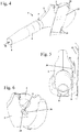
- Fig. 1 shows a hand-operated, hand-carried blower 1 as an exemplary embodiment of a hand-held tool.
- the blower 1 has a housing 2 on which a handle 3 is arranged.
- An operating lever 4 is pivotably mounted on the handle 3.
- a blower pipe 5 is formed on the housing 2, through which a blower unit arranged in the housing 2 is formed 13 ( Fig. 2 ) promotes a blown air stream.
- a nozzle 6 is pushed onto the blowpipe 5.
- the nozzle 6 is advantageously exchangeable so that an operator can attach a nozzle 6 with the desired nozzle shape to adapt to the intended use of the blower 1.
- a blow-out opening 8 is formed on the nozzle 6 through which the blown air flow leaves the blower 1 in a blow-out direction 11.
- Fig. 1 shows the blower 1 in a working position 10.
- the blowout direction 11 is inclined downward relative to a horizontal 12 by a blowout angle ⁇ .
- the blow-out angle ⁇ can be, for example, from about 10 ° to about 70 °.
- the operator swivels the blower 1 in the vertical direction, as indicated by the double arrow 37, so that the blowout direction 11 changes and the blown air flow can be directed towards the material to be blown away.
- the blown air flow is sucked in via a suction opening 7, which in the working position 10 is laterally behind an operator 19 ( Fig. 3 ) lies.
- the blow-out opening 8 is directed forwards in relation to the operator 19.
- the blower 1 has a connecting device 9, which is used for connection to a holder 21 ( Fig. 3 ) is used on an operator 19. On the connecting device 9, the blower 1 can be pivoted about a pivot axis 27 running horizontally in the working position 10, as will be explained in more detail below.
- Fig. 2 shows the structure of the blower 1 in detail.
- the fan unit 13 comprises a drive motor 14 which drives at least one fan wheel (not shown) to rotate.
- the drive motor 14 is arranged in the blowpipe 5.
- An annular space is formed between the drive motor 14 and the blowpipe 5, through which the fan wheel conveys the working air flow.
- the fan unit has a non-rotating stator 15. Downstream of the fan impeller (not shown) and the stator 15, a guide element 16 is provided, which is formed approximately as a rounded cone and on its
- the blower unit 13 conveys the blown air flow in the direction of a central longitudinal axis 18 of the blower pipe 5.
- the blower unit 13 is designed as an axial blower in the exemplary embodiment. However, a design as a diagonal fan can also be advantageous. The direction of inflow into the fan and the direction of outflow from the fan run approximately in the same direction.
- a control 50 arranged in the housing 2 is used to control the drive motor 14. Downstream of the guide element 16, the blowpipe 5 in the working position 10 is bent slightly downwards, while the nozzle 6 is straight in the exemplary embodiment.
- the blower 1 has a center of gravity 17 which, in the exemplary embodiment, lies in the area of the drive motor 14. Another position of the center of gravity 17 can also be advantageous. Different positions of the center of gravity 17 can result for different nozzles 6.
- the blower 1 is designed in such a way that the center of gravity 17 lies under the handle 3 in the working position 10. As a result, the operator only needs a small tilting moment about the horizontal pivot axis 27 ( Fig. 1 ) or a pivot axis extending in the longitudinal direction of the blower 1.
- the connecting device 9 also has a vertical pivot axis 29, which also passes through the pivot point 17 and intersects the handle 3.
- Fig. 3 shows schematically an arrangement of the blower 1 on an operator 19.
- the blower 1 is supported on the operator 19 via a support device 20.
- the support device 20 comprises a holding plate 22 which, in the exemplary embodiment, is carried by the operator via a hip belt 23 and a leg belt 24.
- Another connection of the holding plate 22 can also be advantageous, for example exclusively via a hip belt or to a belt arrangement that also includes shoulder belts and / or other belts.
- the holder 21, on which the connecting device 9 is held, is formed on the holding plate 22.
- the vertical pivot axis 29 is arranged in a vertical plane 26 which the longitudinal center axis 18 of the blowpipe 5 ( Fig. 2 ) contains.
- the vertical plane 26 has a holder 21 in the working position 10 Distance measured in the horizontal direction and relative to the operator in the lateral direction a.
- the blower 1 hangs next to the operator 19 during operation.
- the blower 1 is supported on the operator 19 exclusively via the holder 21 and the holding plate 22.
- the housing 2 of the blower 1 is not in contact with the holding plate 22.
- the support takes place exclusively via the connecting device 9.
- the horizontal pivot axis 27 is also shown.
- the distance a is measured parallel to the horizontal pivot axis 27.
- the center of gravity 17 is advantageously close to the vertical plane 26 which contains the longitudinal center axis 18 of the blowpipe 5.
- the center of gravity 17 lies in the vertical plane 26.
- the operator 19 also swivels the blower 1 about the vertical swivel axis 29.
- the blow-out opening 8 moves to the right and left, as indicated by the double arrow 39. Due to the distance a, the pivoting movements in the direction of the double arrows 37 and 39 can be carried out without the movement being impaired by the holding plate 22.
- the holding plate 22 has slots 25 for fixing the hip belt 23 and the leg belt 24.
- the recoil force R is also shown schematically, which a blown air flow exiting from the blow-out opening 8 during operation exerts on the blower 1.
- the recoil force R is completely absorbed via the connecting device 9 during operation and diverted into the holder 21 and the holding plate 22.
- the recoil force R is thereby absorbed by the leg of the operator 19 and not via a hand arranged on the handle 3. As a result, the strain on the operator, particularly in the wrist, is kept low.
- the connecting device 9 comprises a bellows 34, which will be described in more detail below.
- a plate 36 is arranged at the end of the bellows 34 protruding from the housing 2.
- the sectional view in Fig. 7 shows the structure in detail.
- the connecting device 9 comprises a connecting pin 33 which is fixed at a first fastening point 30 on the holding plate 22 and at a second fastening point 31 on the blower 1.
- the first fastening point 30 is formed by a receptacle 28 on the holding plate 22.
- insertion aids 40 are provided above the receptacle 28, which are designed as sheet metal sections protruding obliquely from the holding plate 22, as well Fig. 8 shows.
- a ball joint 32 is provided, with which the blower 1 is pivotably mounted with respect to the connecting pin 33.
- the ball joint 32 allows pivoting movements about the vertical pivot axis 29 and about the horizontal pivot axis 27.
- a tilting of the blower 1 about an approximately parallel to the longitudinal center axis 18 ( Fig. 2 ) and the axis 49 running through the ball joint 32 is possible over a small angular range.
- the connecting pin 33 is surrounded by the bellows 34.
- the connecting pin 33 protrudes into a housing receptacle 35, which is designed as a recess in the housing 2.
- the ball joint 32 is provided on the bottom of the housing receptacle 35.
- the second fastening point 31 is provided in the center of the housing 2 and lies together with the center of gravity 17 on the vertical pivot axis 29.
- the second fastening point 31 lies with the center of gravity 17 in the vertical plane 26 and close to the longitudinal center axis 18 of the blowpipe 5 ( Fig. 3 ).
- the longitudinal center axis 18 lies in the vertical plane 26.
- the bellows 34 causes the connecting pin 33 to be centered in the housing receptacle 35. As a result, the connecting pin 33 protrudes approximately perpendicular to the vertical plane 26 from the housing 2 of the blower 1.
- the vertical plane 26 to the holding plate 22 has the distance a.
- the distance a is measured perpendicular to the vertical plane 26.
- the blower 1 is held on the ball joint 32 to swing freely in a structurally predetermined angular range.
- the housing 2 of the blower 1 to the holding plate 22 has a side Distance b and does not touch the holding plate 22 in the working position 10.
- the distance b is chosen so that there is sufficient mobility of the blower 1 during operation.
- the distance a is advantageously from about 5 cm to about 15 cm, in particular from about 7 cm to about 11 cm. A distance a of approximately 10 cm has proven to be particularly advantageous.
- Fig. 7 also shows the weight F of the blower, which acts vertically downwards from the center of gravity 17. The weight F exerts a tilting moment at the first fastening point 30. This tilting moment is completely absorbed by the receptacle 28.
- Fig. 8 shows, formed in the exemplary embodiment as a sheet metal 41 which has an approximately vertical slot 51 for the connecting pin 33.
- the sheet metal 41 is fixed on the holding plate 22 at a distance from the holding plate 22.
- shims 42 which are shown in FIG Fig. 9 are shown, underlaid between the holding plate 22 and the sheet metal 41.
- the edges of the sheet metal 41 delimiting the slot 51 form lateral rails 38 behind which the plate 36 is guided. Due to the comparatively large extension of the plate 36 in the vertical direction, the tilting moment exerted by the weight F at the first fastening point 30 is introduced from the plate 36 into the rails 38 and thus into the holding plate 22.
- the plate 36 is fixed and immovably connected to the connecting pin 33 under the forces usually acting during operation. As a result, the weight F of the implement is supported at the first fastening point 30.
- Fig. 9 shows the design of the connecting device 9 in detail.
- the bellows 34 has a first end 44 which is held between a collar 52 on the plate 36 and a thickening 53 of the connecting pin 33.
- the first end 44 of the bellows 34 is held at a small distance from the plate 36 so that the sheet metal 41 can engage between the first end 44 of the bellows 34 and the plate 36.
- a second end 45 of the bellows 34 is held on the housing 2 on its outer circumference.
- the second end 45 is pressed against the wall of the housing 2 by a ring 43 arranged in the bellows 34.
- the connecting pin 33 has a shoulder 46 on which the diameter of the connecting pin 33 increases in the direction of the first fastening point 30.
- the shoulder 46 forms a stop for the connecting pin 33.
- the connecting pin 33 can be pushed into the ball joint 32 up to the shoulder 46.
- Fig. 10 the tilting movement of the blower 1 about the axis 49 is indicated by a double arrow 47.
- the inside diameter of the housing receptacle 35 in the vertical sectional plane shown through the connecting pin 33 corresponds approximately to the outside diameter of the bellows 34.
- the pivoting movement about the axis 49 in the direction of the double arrow 47 of the bellows 34 is limited. Tilting movements about the axis 49 are only possible insofar as the elasticity of the bellows 34 allows this.
- a receiving space 48 is formed in the housing 2 on the side of the connecting pin 33 facing away from the plate 36. If the connecting device 9 is not required, the connecting pin 33 can be pressed into the housing 2 until the in Fig. 11 shown position is reached. The free end of the connecting pin 33 protrudes into the receiving space 48. The bellows 34 is compressed when the connecting pin 33 is pushed into the housing 2. In the position pressed into the housing 2, the plate 36 closes approximately level with the outside of the housing 2 and closes in the position shown in FIG Fig. 11 Section plane shown the housing receptacle 35 largely.
- FIG. 3 shows an embodiment of a connecting device 59 which comprises a connecting pin 63.
- the connecting device 59 is provided on a blower which has a housing 62.
- the construction of the blower essentially corresponds to that shown in the previous figures. Elements that correspond to one another are denoted by the same reference symbols in all figures.
- the housing 62 in Fig. 12 has two housing receptacles 35 which are open on opposite sides of the housing 62.
- the connecting pin 63 penetrates the housing 62.
- a first end 64 of the connecting pin 63 protruding from the housing 62 carries a plate 36.
- the end 65 of the connecting pin 63 protruding from the housing 62 on the opposite side also carries a plate 36 can be arranged on a holder 21 arranged on the right side of an operator 19 and on a holder 21 arranged on a left side of the operator 19.
- the connecting pin 63 protrudes from the housing 62 only on one side of the housing 62 and that the connecting pin 63 is displaceable in its longitudinal direction, so that the connecting pin 63 protrudes from the housing 62 either on one side of the housing or the other .
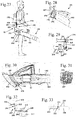
- the Figures 13 and 14 show an embodiment of a blower 71, the structure of which essentially corresponds to that of the blower 1.
- the design of the connecting device 9 also corresponds to that of the blower 1.
- the bellows 34 is not shown in the figures.
- the blower 71 has a housing 72 on which a handle 73 is arranged.
- a guide knob 74 is arranged on the housing 72 on the forward-facing side of the handle 73. If the blower 71 is fixed to the holding plate 22 via the support device 20, then the blower 71 has swung out. The operator can thereby pivot the blower 71 on the guide knob 74 in the horizontal and vertical direction by simply pressing lightly with his hand and thus direct the blown air flow in the desired blowing direction. As a result, even with a blower 71 with a very high blowing power, it is possible to work with little fatigue.
- the Figures 13 and 14 also show the shape of the housing receptacle 35.
- the housing receptacle 35 has two sections 75 which are approximately in the shape of a segment of a circle. A section 75 protrudes from a central position of the connecting pin 33 in the working position 10 and in relation to an operator who carries the blower 71, and another section 75, which is also formed in the shape of a segment of a circle, protrudes to the rear.
- the blow-out opening 1 of the blower 71 compared to the Connecting pin 33 can be pivoted to the right and left.
- the shape of the housing receptacle 35 determines the possible pivot angle for the blower 71.
- the walls of the housing receptacle 35 form a stop for the in Figures 13 and 14 bellows 34, not shown.
- FIGS 15 and 16 show an embodiment of a blower 81, on the housing 82 of which a handle 83 and a guide knob 84 arranged in front of the handle 83 are provided. While the guide knob 74 has a flattened shape, the guide knob 84 is approximately spherical.
- the blowers 1, 71 and 81 have an electric drive motor 14.
- a rechargeable battery can be arranged on the blower 1, 71, 81 to supply the drive motor 14 with energy.
- a comparatively large battery is necessary.
- a battery carried on the back can be provided which is connected to the blower 1, 71, 81 via a power line.
- Fig. 17 shows an exemplary embodiment of a blower 91 which is connected to a backpack arrangement 102 via a support device 90.
- the blower 91 has a housing 92 on which a handle 93 is provided.
- the handle 93 like the handles of the blowers 1, 71, 81, is arranged on the top of the housing 92 and in the longitudinal direction of the blower 91, i.e. approximately parallel to the longitudinal center axis 18 of the blower tube 5 ( Fig. 2 ) aligned.
- An operator 19 uses the handle 93 to guide the blower 91 in operation.
- the handle 93 lies approximately above the center of gravity 17.
- the backpack assembly 102 comprises FIG Fig. 17 shoulder straps 103 shown schematically, with which the backpack arrangement 102 is carried by the operator on his back.
- On the backpack assembly 102 is an in Fig. 17 schematically shown energy storage unit 104 is provided.
- the energy storage unit 104 is advantageous a battery.
- the energy storage unit 104 is connected to the blower 91 via an energy line 115, in particular a power cable.
- the support device 90 comprises a connecting device 99 which is fixed at a first fastening point 100 on the backpack arrangement 102 and at a second fastening point 101 on the blower 91.
- the second fastening point 101 is provided on a suction opening 97 of the blower 91, which is arranged on the side of the blower 91 facing backwards relative to the operator 19 during operation, i.e. on the side of the blower 91 facing away from a blow-out opening.
- the second fastening point 101 lies together with the center of gravity 17 in a vertical plane which contains the longitudinal center axis 18 of the blowpipe 5.
- the second fastening point 101 is arranged offset to the rear with respect to the center of gravity 17.
- the first fastening point 100 is shown in the exemplary embodiment Fig. 17 arranged on the high side of the backpack arrangement 102 facing the blower 91.
- the first fastening point 100 has a distance c measured laterally and horizontally from the second fastening point 101.
- the backpack arrangement 102 forms a holder for the connecting device 99 carried by the operator 18.
- the connecting device 99 is designed as a linkage projecting laterally and obliquely downward.
- a pivot joint 106 is provided at the first fastening point 100, with which the connecting device 99 can be folded up. From the in Fig. 17 However, the connection device 99 cannot be folded further downward in the position shown. As a result, the connecting device 99 can partially absorb the weight F of the blower 91 and completely absorb the tilting moment caused by the lateral distance c between the center of gravity 17 and the first fastening point 100.
- Fig. 17 shows the arrangement in a connected state in which the blower 91 is connected to the backpack arrangement 102 via the connecting device 99.
- the connecting device 99 takes the repulsive force R ( Fig. 18 ) as well as part of the weight F and the overturning moment generated by the weight F due to the distance c.
- the tilting moment that is exerted in front of the second fastening point 101 due to the position of the center of gravity 17 is not absorbed by the connecting device 99, but rather has to be maintained by the operator 19.
- Fig. 18 shows the arrangement in an unconnected state 95.
- the blower 91 is not connected to the backpack arrangement 102 via the connecting device 99.
- the blower 91 is separated from the connecting device 99 at the second connection point 101.
- the blower 91 is separated from the backpack arrangement 102 at the first connection point 100 and the connection device 99 is held firmly on the blower 91.
- the connecting device 99 comprises a first section 107 which is held on the backpack arrangement 102 via the swivel joint 106.
- the connecting device 99 also comprises a second section 108, which can be pushed telescopically into the first section 107, as indicated by the double arrow 109. This allows the length of the connecting device 99 and thus the position of the second fastening point 101 to be adjusted during operation.
- the position of the sections 107 and 108 with respect to one another can advantageously be fixed, so that the weight F is also partially absorbed by the connecting device 99.
- the backpack arrangement 102 has a recess 105 on the upper side facing the blower 91.
- the connecting device 99 can be transferred into a transport position in the disconnected state 95 by sliding the section 108 into the section 107 and then folding the section 107 upwards until the section 107 rests against the backpack arrangement 102 and is at least partially arranged in the recess 105 is.
- the folding up of the section 107 is indicated by a double arrow 114.
- the housing 92 of the blower 91 has a recess 110 on the side facing away from the blow-out opening 8, on which the second fastening point 101 is formed.
- the recess 110 is approximately funnel-shaped.
- a pin 112 is provided, which protrudes into an elongated hole 111 of the second section 108.
- the pin 112 of the housing 92 of the blower 91 can be pivoted about a horizontal pivot axis 117 relative to the second section 108 of the connecting device 99.
- the pin 112 is arranged on a sensor 113 which detects whether the second section 108 is arranged on the pin 112 or not. The sensor 113 thus recognizes the connected state 94 and the disconnected state 95.
- the sensor 113 is connected to the controller 50 of the blower 91.
- Fig. 20 shows an embodiment of a blower 121, which is connected to a backpack arrangement 132 via a support device 120.
- Fig. 20 shows the connected state 94, in which the backpack arrangement 132 is in operation recoil force R generated by the outflowing blown air as well as that due to the lateral distance c ( Fig. 18 ) the tilting moment caused between the center of gravity 17 of the blower 121 and the first fastening point 130 is absorbed by the backpack arrangement 132.
- the blower 121 has a housing 122 on which a handle 123 is provided for guiding the blower 121 during operation.
- the support device 120 comprises a connecting device 129 which is fixed at a first fastening point 130 on a base plate 135 of the backpack arrangement 132.
- the connecting device 129 is connected to the blower 121 at a second fastening point 131, which is arranged on the underside of the housing 122 of the blower 121.
- the connecting device 129 is designed telescopically so that the length of the connecting device 129 can be adjusted by the operator.
- the connecting device 129 like the connecting device 99, protrudes laterally obliquely downward from the backpack arrangement 132.
- the backpack arrangement 132 is secured to the operator via a hip strap 133.
- the backpack arrangement 132 comprises the base plate 135 and a back plate 137, which in the exemplary embodiment is arranged in the region of the hip belt 133.
- An energy storage unit 134 in particular a rechargeable battery, is fixed to the backpack arrangement 132.
- the energy line via which the energy storage unit 134 is connected to the blower 121 both in the connected state 94 and in the disconnected state 95 is shown in FIG Fig. 20 Not shown.
- Fig. 21 shows the floor plate 135 from the side facing the floor during operation.
- the base plate 135 has, in addition to the first fastening point 130 arranged on the right side of the base plate 135, a second, alternative fastening point 136 which is arranged on the left side of the base plate 135.
- the connecting device 129 for guiding the blower 121 with the right hand can be fixed at the fastening point 130 and for guiding the blower 121 with the left hand at the alternative fastening point 136.
- the second fastening point 131 is arranged on the underside of the housing 122 in the rear region of the blower 121. As a result, part of the weight F of the blower 121 rests on the second fastening point 131 during operation and is introduced into the backpack arrangement 132 via the support device 120.
- Fig. 22 also shows the structure of the connecting device 129 from a first section 127, which is fixed at the first fastening point 130 on the backpack arrangement 132, and a second section 128, which is telescopically connected to the first section 127 and which is connected to the second fastening point 131 with the Housing 122 is connected.
- Fig. 23 shows a schematic and simplified structure of the connecting device 129 at the first fastening point 130 and the second fastening point 131.
- the connecting device 129 has a spherical head 124 which protrudes into a corresponding spherical head receptacle of the backpack arrangement 132 and is thereby positively connected to the backpack arrangement 132 is.
- the connection at the first fastening point 130 is in particular releasable.
- the ball head receptacle is designed in such a way that the tilting moment exerted by the weight F due to the lateral distance between the center of gravity 17 and the fastening point 130 can be absorbed at the first fastening point 130 at the first fastening point 130.
- a ball head 125 is provided, which protrudes into a receptacle 126 of the housing 122.
- the ball head 125 and the receptacle 126 are matched to one another in such a way that the blow-out opening 8 of the blower 121 can be pivoted up and down at the desired angle and to the right and left in the horizontal direction during operation.
- Fig. 24 shows an exemplary embodiment of a blower 141 which is supported on a backpack arrangement 152 via a support device 140.
- the backpack arrangement 152 comprises a backpack 155 on which an energy storage unit 154, in particular a battery, is arranged. It is a connecting the energy storage unit 154 and the blower 141, in Fig. 24 Power line not shown provided.
- the support device 140 has a connecting device 149.
- a laterally projecting carrier 143 of the connecting device 149 is fixed to the back stretcher 155.
- the carrier 143 has fastening openings 146 to which an arm 144 of the connecting device 149 can be fixed in different positions.
- the arm 144 has a swivel joint 145.
- the arm 144 can, however, also be designed to be rigid.
- the arm 144 protrudes obliquely downward in the radial direction of the carrier 143 in relation to the longitudinal center axis of the carrier 143.
- a second fastening point 151 is provided, at which the arm 144 is fixed to a housing 142 of the blower 141.
- the second fastening point 151 is arranged in the area of a suction opening 147.
- the second fastening point 151 is advantageously in the extension of the longitudinal center axis 18 of the blowpipe 5.
- the second fastening point 151 is particularly advantageously in the extension of the vector of the recoil force R ( Fig. 4 ), so that the recoil force R is completely absorbed at the second fastening point 151 and no moment is generated around the second fastening point 151.
- the carrier 143 is fixed at a first fastening point 150 on the backpack 155 of the backpack arrangement 152.
- the first fastening point 150 is provided in the lower lateral area on the backpack 155.
- the backpack assembly 152 also includes a waist belt 153.
- the first fastening point 150 to the second fastening point 151 has a distance c measured in the lateral direction of the operator and in the horizontal direction. Because of the distance c, the weight F of the blower 141 exerts a tilting moment at the first fastening point 150, which is absorbed at the first fastening point 150 and diverted into the backpack 155.
- Fig. 25 shows schematically the design of the second fastening point 151.
- a cardan joint 156 is provided, which connects the arm 144 to the housing 142 of the blower 141.
- the universal joint has a first, horizontally extending pivot axis 157 and a second, vertically extending Pivot axis 158.
- the first pivot axis 157 advantageously runs in a lateral direction and thereby enables the blow-out opening to be pivoted up and down, while the second pivot axis 158 enables the blow-out opening to be pivoted to the right and left.
- Fig. 26 shows an embodiment of a support device 160 which is provided on a blower 161.
- the blower 161 has a housing 162 which has a first section 163 and a second section 164.
- the fan unit is arranged in the first section 163, and a nozzle with a blow-out opening can be arranged on the second section 164.
- a second section 164 of the housing 162 comprises the suction opening 167.
- a pivot joint 165 is provided, which is designed in the manner of a bellows and a movement of the first section 163 about a first, horizontally lying pivot axis 177 and about a second, vertically lying pivot axis 178 allows.
- the first pivot axis 177 is aligned in the lateral direction of the operator 19.
- the support device 160 comprises a connecting device 169 which connects the blower 161 to a backpack arrangement 172.
- the backpack arrangement 172 comprises a hip belt 173 and shoulder straps (not shown).
- An energy storage unit 174 is fixed to the backpack arrangement 172.
- the connecting device 169 comprises a carrier 175 which is bent in an L-shape and which is fixed at a first fastening point 170 on the underside of the backpack arrangement 172.
- a section of the carrier 175 protrudes vertically downward from the first fastening point 170.
- the angled section of the carrier 175 protrudes outwards in a lateral direction and approximately horizontally in relation to the operator 19.
- the second section 164 of the housing 162 of the blower 161 is suspended from the carrier 175.
- a groove-shaped receptacle 176 is formed on the section 164 of the housing 162 and engages over the carrier 175.
- the receptacle 176 advantageously partially encloses the carrier 175, so that a locking fixation results. It can be provided that the receptacle 176 is held firmly on the carrier 175. It can however, a pivoting movement of the section 164 of the housing 162 about the longitudinal axis of the rod 175 can also be provided.
- the first section 163 of the housing 162 forms part of the support device 160 and is fixed at a second fastening point 171 on the swivel joint 165. Part of the weight F of the blower 161 and the recoil force R generated by the air flow emerging from the blower tube 5 are absorbed via the second section 164 and the carrier 175.
- Fig. 27 shows an embodiment of a blower 181, which can be connected to a backpack arrangement 192 via a support device 180.
- Fig. 27 shows the arrangement in the disconnected state 95.
- the blower 181 has a housing 182 with a first section 183 and a second section 184, which are articulated to one another via a swivel joint 185.
- the swivel joint 185 is designed as a bellows in the exemplary embodiment. However, a different design of the swivel joint 185 can also be advantageous.
- the two sections 183 and 184 can be pivoted relative to one another about a horizontal and a vertical axis.
- the support device 180 comprises a connecting device 189 which is fixed at a first fastening point 190 on the backpack arrangement 192.
- a second fastening point 191 is formed at the connection point between the first section 183 of the housing 182 and the second section 184 of the housing 182.
- the connecting device 189 comprises a connecting element 194 which is designed as a lever linkage.
- the connecting element 194 can be connected to the second section 184 of the housing 182 at a connection point 193.
- the connecting element 194 and the second section 184 of the housing 182 are not connected to one another.
- the connections at the first fastening point 190 and at the second fastening point 191 cannot be released.
- connection point 193 is provided on a longitudinal side of the blower 181 adjacent to a suction opening 187.
- a rail 195 is provided, in which a fastening element 196 is mounted so as to be longitudinally displaceable in the direction of the double arrow 197.
- Fig. 29 shows the design of the connecting element 194 schematically in detail.
- the connecting element 194 has a first section 201, on which a second section 202 is held displaceably in the direction of a double arrow 211.
- the second section 202 has an elongated hole 205 at the connection point to the first section 201.
- a third section 203 is pivotably mounted on the second section 202 via a pivot joint 206, as indicated by the arrow 208.
- a fourth section 204 is mounted in the manner of a telescope so as to be longitudinally displaceable in the direction of the double arrow 209.
- a latching element 210 is provided to fix the sections 203 and 204 in relation to one another.
- the sections 201, 202, 203 and 204 are designed as levers in the exemplary embodiment.
- a stop 198 is provided between the first section 183 and the second section 184 on the pivot joint 185.
- the stop 198 comprises a first stop element 199, which is fixed on the first section 183, and a second stop element 200, which is fixed on the second section 184.
- the stop elements 199 and 200 rest against one another in the compressed state of the swivel joint 185.
- the stop 198 limits the distance by which the swivel joint 185 can be compressed to a maximum.
- Fig. 31 shows a view of the suction opening 187.
- a socket 212 is provided on the suction opening 187, into which the power line 207 ( Fig. 27 ) can be plugged in.
- the Figures 32 and 33 show an alternative connection of the connecting element 194 to a suction opening 217.
- the first section 201 is fixed to a backpack arrangement 192.
- the fourth section 204 protrudes into a groove 218 on a suction opening 217 of a blower.
- the groove 218 has latching depressions 220 on one longitudinal side.
- the fourth section 204 carries a latching element 221, which is mounted in a spring-loaded manner via a spring element 222.
- the representation in Fig. 33 is only schematic. Any suitable latching device can be provided.
- the fourth section 204 can be fixed in different positions on the suction opening 217 via the latching device.
- the connecting element 194 is part of a connecting device 219.
- FIGS. 34 to 36 show an alternative connection of a connecting device to a holder, for example a backpack arrangement or a blower.
- a fastening plate 226 and a counter plate 227 are provided.
- the fastening plate 226 and the counter plate 227 can be connected to and detached from one another.
- Fastening plate 226 and counter plate 227 can be provided at a first fastening point, at a second fastening point or between two sections of a connecting device.
- the fastening plate 226 is part of the connecting device and the counter plate 227 is to be arranged on the holder or the blower or the fastening plate 226 is to be arranged on the holder or the blower, and the counter plate 227 is part of the connecting device.
- the fastening plate 226 has a plurality of pegs 228. In the exemplary embodiment, four pegs 228 are provided which are chamfered to facilitate insertion.
- the fastening plate 226 also has two locking elements 230, each of which is pivotably mounted via a pivot bearing 231. The pivoting movement of the locking elements 230 is shown in FIG Fig. 35 indicated by the arrow 232.
- the counter plate 227 has recesses 229 for the pegs 228.
- the recesses 229 can also be designed as openings into which the pegs 228 engage.
- For the Locking elements 230 are provided with recesses 233. In the locked state, the locking elements 230 engage behind the edge of the depressions 233 and are thereby fixed on the counter plate 227.
- the recesses 233 can also be designed as openings.
- Fig. 37 shows an operator-carried blower 241, which is operated via an in Fig. 39 connecting device 239 shown schematically is to be connected to a backpack.
- Fig. 37 shows the blower 241 in the disconnected state 94.
- the connecting device 239 comprises a pin 242, which, like Fig. 38 shows, in the connected state 95 protrudes into a receptacle 243 of the connecting device 239.
- the pin can be pivoted in the receptacle 243 about a pivot axis 247 which is arranged vertically in the exemplary embodiment.
- a latching element 244 is provided, which can be a resilient ring, for example.
- the connecting device 239 comprises a section 246 which is connected to the receptacle 243 via a swivel joint 245.
- the section 246 can be attached directly to the backpack or connected to the backpack via further elements.
- Fig. 40 shows an embodiment of a blower 251, which is connected to a backpack arrangement 272 via a support device 250.
- the blower 251 has a housing 252 which has a suction opening 257 on its side facing rearward during operation.
- a receptacle 258 for a connecting device 259 is provided approximately in the middle.
- the connecting device 259 is fixed at a first fastening point 260 on the backpack arrangement 272.
- the connecting device 259 is in the in Fig. 40
- the disconnected state 94 shown is not connected to the blower 251.
- the first fastening point 260 is arranged in relation to the operator 19 at the lower end of the right long side of the backpack arrangement 272.
- the connecting device 259 is connected to the backpack arrangement 272 via a swivel joint 264.
- a Energy storage unit 274 in particular a battery, set.
- the connecting device 259 comprises a first section 262, which is held on the swivel joint 264, and a second section 263, which can be telescoped into the first section 262.
- a connecting plate 265, which can be fixed in the receptacle 258, is held at the end of the second section 263 facing away from the first section 262.
- the backpack arrangement 272 has a recess 267 on its right long side, which is used to receive the connecting device 259 in the disconnected state 94.
- the two sections 262 and 263 are pushed into one another and then folded onto the backpack arrangement 272 via the swivel joint 264 until the connecting device 259 lies at least partially in the recess 267.
- Means for fixing the connecting device 259 in the recess 267 are advantageously provided.
- the connected state 95 is shown in detail.
- the connecting plate 265 is arranged at the second fastening point 261 in the receptacle 258.
- the connecting plate 265 can be fixed in the receptacle 258 via a magnetic connection, for example. Another type of fixation can also be advantageous.
- the connecting plate 265 is connected to the second section 263 via a pivot bearing 266.
- the pivot bearing 266 advantageously allows pivoting movements in the lateral direction and about a horizontal pivot axis.
- the connecting plate 265 is in particular sprung.
- Fig. 42 shows an embodiment of a blower 271, which is connected to a backpack arrangement 282 via a support device 270.
- the support device 270 comprises a connecting device 279 which is fixed at a first fastening point 280 on the backpack arrangement 282.
- the first fastening point 280 is provided on the lower edge of the backpack arrangement 282 which is on the right in relation to the operator 19.
- the connector 279 protrudes laterally obliquely downwards and is designed as a rigid rod.
- the connecting device 279 has a connecting element 285 which is used to connect to a receptacle 278 of the housing 252 of the blower 271 at a second fastening point 281.
- the housing of the blower 271 is identical to the housing 252 of the blower 251 and differs only in the receptacle 278.
- FIG. 42 shows an embodiment of a blower 271, which is connected to a backpack arrangement 282 via a support device 270.
- the support device 270 comprises
- FIG. 40 the receptacle 278 is arranged centrally in a suction opening 257 of the blower 271.
- FIG. 42 shows the arrangement in the disconnected state 94, in which the connecting element 285 is not arranged in the receptacle 278.
- a power line which connects the blower 271 to the backpack arrangement 282 even in the disconnected state 94 is shown in FIG Fig. 42 Not shown.
- Fig. 43 shows the receptacle 278 schematically.
- the receptacle 278 comprises a coupling 287 which is held on the housing 252 via a joint 286 and can thereby be aligned with the connecting element 285.
- the coupling 287 is arranged in a recess 288, which is advantageously designed in the shape of a funnel, so that the connecting element 285 is guided through the walls of the recess 288 to the coupling 287.
- the clutch 287 can be a magnetic clutch, for example.
- Fig. 44 shows an embodiment of a magnetic coupling schematically.
- the connecting device 289 which is used for connection to a backpack arrangement, carries a magnet 292.
- a receptacle 290 is formed on the blower, at the bottom of which an actuating element 293 is provided, which is spring-mounted via a spring 294.
- Two holding arms 295 are connected to the actuating element 293, each of which is connected to the actuating element 293 via a pivot bearing 296. If the connecting device 289 is moved into the receptacle 290 in the direction of the arrow 297, the actuating element 293 is counter to the force of the spring 294 in FIG Fig. 44 moved to the right.
- the holding arms 295 have counter bearings that a movement of the holding arms 295 in Fig. 44 to prevent right. As a result, the holding arms 295 pivot on the pivot bearings 296 into the receptacle 290 and engage in a recess 298 of connector 289. A form-fitting securing of the connecting device 289 is thereby achieved.
- the arrangement is advantageously provided at a second fastening point 291.
- the support device 20, 90, 120, 140, 160, 180, 270 supports the implement in such a way that the tilting moment exerted by the weight of the implement at the first fastening point due to the lateral distance a, c is at least partially supported .
- the weight F of the working device and / or the recoil force R which is generated by a blown air flow emerging from the blower, is advantageously absorbed at least partially, advantageously completely.
- Location information such as "in front of”, “behind”, “to the side”, “above”, “below”, etc. in all exemplary embodiments relate to the operator 19 and a working position 10 of the blower.
Description
Die Erfindung betrifft eine Anordnung mit einem handgeführten Arbeitsgerät und einer Abstützvorrichtung der im Oberbegriff des Anspruchs 1 angegebenen Gattung.The invention relates to an arrangement with a hand-held tool and a support device of the type specified in the preamble of
Aus der
Aus der
Aus der
Die
Der Erfindung liegt die Aufgabe zugrunde, eine Anordnung mit einem handgeführten Arbeitsgerät und einer Abstützvorrichtung zu schaffen, die ein ergonomisches und kraftsparendes Arbeiten mit dem Arbeitsgerät ermöglicht.The invention is based on the object of creating an arrangement with a hand-held implement and a support device which enables ergonomic and energy-saving work with the implement.
Bezüglich der Anordnung mit einem handgeführten Arbeitsgerät und mit einer Abstützvorrichtung wird die Aufgabe durch eine Anordnung mit den Merkmalen des Anspruchs 1 gelöst.With regard to the arrangement with a hand-held tool and with a support device, the object is achieved by an arrangement with the features of
Die Anordnung besitzt eine Abstützvorrichtung zur Abstützung des Arbeitsgeräts im Betrieb. Es ist eine Verbindungseinrichtung vorgesehen, die an einer ersten Befestigungsstelle an einer vom Bediener zu tragenden Halterung und an einer zweiten Befestigungsstelle an dem Arbeitsgerät gehalten ist. An der zweiten Befestigungsstelle ist die Verbindungseinrichtung um mindestens eine Schwenkachse schwenkbar gelagert. Es ist vorgesehen, dass der Schwerpunkt des Arbeitsgeräts und die erste Befestigungsstelle in Arbeitslage des Arbeitsgeräts einen in horizontaler und bezogen auf den Bediener in seitlicher Richtung gemessenen Abstand zueinander aufweisen. Die erste Befestigungsstelle liegt demnach bezogen auf den Bediener neben dem Schwerpunkt des Arbeitsgeräts. Die Halterung besitzt an der ersten Befestigungsstelle Mittel zur mindestens teilweisen Abstützung des Kippmoments, das die Gewichtskraft des Arbeitsgeräts an der ersten Befestigungsstelle aufgrund des seitlichen Abstands ausübt. Über die Halterung wird demnach nicht nur die Gewichtskraft aufgenommen, sondern auch das von der Gewichtskraft an der ersten Befestigungsstelle erzeugte Kippmoment. Das Kippmoment wird dabei nicht an einer Halteplatte oder dgl. aufgenommen, an der sich das Arbeitsgerät abstützt, sondern an der ersten Befestigungsstelle selbst. Dadurch, dass das Kippmoment mindestens teilweise an der ersten Befestigungsstelle von der Halterung aufgenommen wird, muss dieses Kippmoment im Betrieb höchstens teilweise vom Bediener aufgenommen werden. Dadurch kann das Arbeitsgerät mit geringem Kraftaufwand bedient werden, so dass ein ermüdungsfreier Betrieb möglich ist.The arrangement has a support device for supporting the implement during operation. A connecting device is provided which is held at a first fastening point on a holder to be carried by the operator and at a second fastening point on the working device. At the second fastening point, the connecting device is mounted pivotably about at least one pivot axis. It is provided that the center of gravity of the working device and the first fastening point in the working position of the working device are at a distance from one another, measured horizontally and laterally in relation to the operator. The first fastening point is accordingly next to the center of gravity of the working device in relation to the operator. At the first fastening point, the holder has means for at least partial support of the tilting moment which the weight of the implement exerts at the first fastening point due to the lateral distance. Accordingly, not only the weight force is absorbed via the holder, but also the tilting moment generated by the weight force at the first fastening point. The tilting moment is not recorded on a holding plate or the like on which the implement is supported, but on the first fastening point itself. Because the tilting moment is at least partially absorbed by the bracket at the first fastening point, this tilting moment must be at most during operation partially be recorded by the operator. As a result, the tool can be operated with little effort, so that fatigue-free operation is possible.
Der seitliche Abstand zwischen dem Schwerpunkt und der ersten Befestigungsstelle beträgt vorteilhaft von etwa 5 cm bis etwa 15 cm, insbesondere von etwa 7 cm bis etwa 11 cm. Als besonders vorteilhaft hat sich ein Abstand von etwa 10 cm herausgestellt. Dadurch kann das Arbeitsgerät an der ersten Befestigungsstelle weitgehend frei hängen, ohne seitlich mit dem Bediener in Kontakt zu kommen. Gleichzeitig ist das von der Halterung aufzunehmende Kippmoment vergleichsweise klein, so dass ein einfacher Aufbau der Halterung möglich ist. Es kann vorteilhaft sein, wenn die Lage der zweiten Befestigungsstelle einstellbar ist. Hierzu sind vorteilhaft die Länge, die Gestalt und/oder die Ausrichtung der Verbindungseinrichtung einstellbar. Auch eine konstruktiv fest vorgegebene Lage der zweiten Befestigungsstelle relativ zur ersten Befestigungsstelle kann jedoch vorteilhaft sein. Auch die Lage der zweiten Befestigungsstelle an dem Arbeitsgerät und/oder die Lage der ersten Befestigungsstelle an der Halterung kann einstellbar sein.The lateral distance between the center of gravity and the first fastening point is advantageously from about 5 cm to about 15 cm, in particular from about 7 cm to about 11 cm. A distance of about 10 cm has proven to be particularly advantageous. As a result, the implement can hang largely freely at the first fastening point without coming into contact with the operator from the side. At the same time, the tilting moment to be absorbed by the holder is comparatively small, so that a simple construction of the holder is possible. It can be advantageous if the position of the second fastening point is adjustable. For this purpose, the length, the shape and / or the alignment of the connecting device can advantageously be adjusted. However, a structurally fixed predetermined position of the second fastening point relative to the first fastening point can also be advantageous. The position of the second fastening point on the working device and / or the position of the first fastening point on the holder can also be adjustable.
Bevorzugt ist die zweite Befestigungsstelle innerhalb des Gehäuses angeordnet. Auch eine Anordnung der zweiten Befestigungsstelle außerhalb des Gehäuses kann jedoch vorteilhaft sein. Vorteilhaft ist die zweite Befestigungsstelle nahe am Schwerpunkt des Arbeitsgeräts angeordnet. Der horizontale Abstand der zweiten Befestigungsstelle zum Schwerpunkt ist vorteilhaft möglichst klein. Um das Kippmoment vollständig an der ersten Befestigungsstelle aufzunehmen, ist vorteilhaft vorgesehen, dass die zweite Befestigungsstelle und der Schwerpunkt des Arbeitsgeräts in einer gemeinsamen vertikalen Ebene liegen. Besonders vorteilhaft liegt der Schwerpunkt etwa senkrecht unter der zweiten Befestigungsstelle. Dadurch ist das Arbeitsgerät an der zweiten Befestigungsstelle sowohl in seitlicher Richtung als auch in einer nach vorne verlaufenden Richtung ausbalanciert gehalten und kann ausgehend von dieser ausbalancierten Lage mit sehr geringem Kraftaufwand vom Bediener verschwenkt werden. Die Gewichtskraft des Arbeitsgeräts wird vollständig an der ersten Befestigungsstelle der Halterung aufgenommen.The second fastening point is preferably arranged within the housing. However, an arrangement of the second fastening point outside the housing can also be advantageous. The second fastening point is advantageously arranged close to the center of gravity of the implement. The horizontal distance between the second fastening point and the center of gravity is advantageously as small as possible. In order to fully absorb the tilting moment at the first fastening point, it is advantageously provided that the second fastening point and the center of gravity of the implement lie in a common vertical plane. The center of gravity is particularly advantageously approximately perpendicular under the second fastening point. As a result, the working device is held balanced at the second fastening point both in the lateral direction and in a forward direction and, starting from this balanced position, can be pivoted by the operator with very little effort. The weight of the implement is completely absorbed at the first fastening point of the bracket.
Vorteilhaft ist das Arbeitsgerät ein Blasgerät, das im Betrieb einen Blasluftstrom durch ein Blasrohr fördert. Die Verbindungseinrichtung nimmt vorteilhaft die im Betrieb von dem austretenden Blasluftstrom erzeugte Rückstoßkraft auf. Insbesondere bei Blasgeräten mit hoher Blasleistung bildet die Rückstoßkraft einen Hauptteil der vom Bediener aufzunehmenden Kräfte. Dadurch, dass die Verbindungseinrichtung im Betrieb die von dem austretenden Blasluftstrom erzeugte Rückstoßkraft aufnimmt, ist ein weitgehend kraftfreies Arbeiten auch mit Blasgeräten mit sehr hoher Blasleistung möglich. Die Belastung des Handgelenks eines Bedieners, über das die Rückstoßkraft üblicherweise aufgenommen wird, ist deutlich verringert.The working device is advantageously a blower which, during operation, conveys a flow of blown air through a blowpipe. The connecting device advantageously absorbs the recoil force generated by the exiting blown air flow during operation. Especially in blowers with high blowing power, the recoil force forms a major part of the forces to be absorbed by the operator. Because the connecting device absorbs the recoil force generated by the exiting blown air flow during operation, it is possible to work largely without force, even with blowers with very high blowing power. The load on the wrist of an operator, via which the recoil force is usually absorbed, is significantly reduced.
Vorteilhaft ist der horizontale Abstand der zweiten Befestigungsstelle zur Längsmittelachse des Blasrohrs möglichst klein. Dadurch kann ein Schwenken des Blasgeräts beim Starten bzw. beim Abstellen des Gebläses vermindert werden. Eine vorteilhafte Anordnung ergibt sich, wenn die zweite Befestigungsstelle und die Längsmittelachse des Blasrohrs in der gemeinsamen vertikalen Ebene liegen, in der auch der Schwerpunkt liegt. Dadurch ergibt sich eine vorteilhafte Ausrichtung des Blasgeräts. Ist das Blasgerät an der zweiten Befestigungsstelle schwenkbar gelagert, so liegen die Längsmittelachse des Blasrohrs und die zweite Befestigungsstelle in Ruhelage des Blasgeräts der gemeinsamen vertikalen Ebene, also wenn am Blasgerät keine äußeren Kräfte wirken, das Blasgerät also nicht in Betrieb ist und der Bediener das Blasgerät nicht aus seiner Ruhelage heraus verschwenkt. Durch die Anordnung der Längsmittelachse des Blasrohrs in der Ebene, in der die zweite Befestigungsstelle und der Schwerpunkt des Arbeitsgeräts liegen, müssen vom Bediener im Betrieb nur sehr geringe Kräfte zum Halten und Führen des Blasgeräts aufgewendet werden. Eine ergonomische Anordnung ergibt sich, wenn die zweite Befestigungsstelle bezogen auf den Bediener hinter dem Schwerpunkt des Arbeitsgeräts liegt. Bei Anordnung der zweiten Befestigungsstelle hinter dem Schwerpunkt des Arbeitsgeräts muss der Bediener allerdings einen Teil der Gewichtskraft selbst tragen.The horizontal distance between the second fastening point and the longitudinal center axis of the blowpipe is advantageously as small as possible. This can reduce the swiveling of the blower when starting or switching off the blower. An advantageous arrangement results when the second fastening point and the longitudinal center axis of the blowpipe lie in the common vertical plane in which the center of gravity is also located. This results in an advantageous alignment of the blower. If the blower is pivotably mounted at the second fastening point, the longitudinal center axis of the blower pipe and the second fastening point lie in the rest position of the blower in the common vertical plane, i.e. when there are no external forces acting on the blower, i.e. the blower is not in operation and the operator is the blower not pivoted out of its rest position. Due to the arrangement of the longitudinal center axis of the blower pipe in the plane in which the second fastening point and the center of gravity of the implement are located, the operator only has to use very little forces to hold and guide the blower during operation. An ergonomic arrangement is obtained when the second fastening point is located behind the center of gravity of the implement in relation to the operator. When arranging the second attachment point behind the The operator has to bear part of the weight himself, however, because of the center of gravity of the working device.
Vorteilhaft besitzt das Arbeitsgerät in Arbeitslage zu der Halterung einen bezogen auf den Bediener in seitlicher Richtung gemessenen Abstand. Dadurch, dass das Arbeitsgerät an der Halterung einen seitlichen Abstand besitzt und nicht an der Halterung anliegt, kann das Arbeitsgerät im Betrieb frei geschwenkt werden, ohne dass die Schwenkbewegung von der Halterung behindert wird. Vorteilhaft ist die Verbindungseinrichtung an der zweiten Befestigungsstelle um eine vertikale Schwenkachse schwenkbar gelagert. Die Schwenkbarkeit um die vertikale Schwenkachse erlaubt ein Schwenken des Arbeitsgeräts in einer horizontalen Ebene. Vorteilhaft ist vorgesehen, dass die Verbindungseinrichtung an der zweiten Befestigungsstelle um eine horizontale Schwenkachse schwenkbar gelagert ist. Dadurch wird eine vertikale Schwenkbewegung des Arbeitsgeräts ermöglicht. Eine einfache Gestaltung ergibt sich, wenn die zweite Befestigungsstelle an einem Kugelgelenk ausgebildet ist.In the working position, the working device advantageously has a distance from the holder that is measured in the lateral direction in relation to the operator. Because the implement has a lateral distance to the holder and does not rest against the holder, the implement can be freely pivoted during operation without the pivoting movement being hindered by the holder. The connecting device is advantageously mounted pivotably about a vertical pivot axis at the second fastening point. The ability to pivot about the vertical pivot axis allows the implement to be pivoted in a horizontal plane. It is advantageously provided that the connecting device is mounted on the second fastening point so as to be pivotable about a horizontal pivot axis. This enables a vertical pivoting movement of the implement. A simple design results when the second fastening point is formed on a ball joint.
Vorteilhaft ist vorgesehen, dass die Verbindungseinrichtung einen Verbindungsstift umfasst. Dadurch ergibt sich ein einfacher Aufbau. In Arbeitslage kragt der Verbindungsstift von der Halterung vorteilhaft etwa horizontal und bezogen auf den Bediener in seitlicher Richtung aus. Der Verbindungsstift ist dabei insbesondere in einer Gehäuseaufnahme des Arbeitsgeräts beweglich angeordnet. Die Verbindungseinrichtung weist vorteilhaft Mittel zur Zentrierung des Verbindungsstifts in der Gehäuseaufnahme auf. Dies ist insbesondere dann vorteilhaft, wenn die Verbindungseinrichtung an einer Befestigungsstelle, insbesondere an der ersten Befestigungsstelle, lösbar ausgebildet ist. Die Zentrierung des Verbindungsstifts vereinfacht die Fixierung des Verbindungsstifts in einer Aufnahme der Halterung.It is advantageously provided that the connecting device comprises a connecting pin. This results in a simple structure. In the working position, the connecting pin protrudes from the holder advantageously approximately horizontally and in a lateral direction relative to the operator. The connecting pin is in particular movably arranged in a housing receptacle of the working device. The connecting device advantageously has means for centering the connecting pin in the housing receptacle. This is particularly advantageous if the connecting device is designed to be detachable at a fastening point, in particular at the first fastening point. The centering of the connecting pin simplifies the fixing of the connecting pin in a receptacle of the holder.
Handgeführte Arbeitsgeräte werden von rechthändigen Bedienern üblicherweise an der rechten Körperseite getragen, während linkshändige Bediener oft ein Tragen an der linken Körperseite bevorzugen. Um eine Anordnung des Arbeitsgeräts sowohl an der rechten Körperseite als auch an der linken Körperseite zu ermöglichen, ist vorteilhaft vorgesehen, dass der Verbindungsstift auf gegenüberliegenden Seiten aus dem Gehäuse ragen kann. Der Verbindungsstift kann dabei dauerhaft auf beiden Seiten des Gehäuses aus dem Gehäuse ragen. Es kann jedoch auch vorteilhaft sein, dass der Verbindungsstift jeweils nur auf einer Gehäuseseite aus dem Gehäuse ragt und auf der gegenüberliegenden Gehäuseseite nicht aus dem Gehäuse hervorsteht. Dadurch wird vermieden, dass der Bediener durch einen Verbindungsstift, der auf der dem Bediener abgewandten Gehäuseseite aus dem Gehäuse ragt, behindert wird.Handheld implements are usually worn on the right side of the body by right-handed operators, while left-handed operators often prefer to be worn on the left side of the body. To an arrangement of the implement both at the To enable the right side of the body as well as the left side of the body, it is advantageously provided that the connecting pin can protrude from the housing on opposite sides. The connecting pin can protrude permanently from the housing on both sides of the housing. However, it can also be advantageous that the connecting pin protrudes from the housing only on one housing side and does not protrude from the housing on the opposite housing side. This prevents the operator from being hindered by a connecting pin which protrudes from the housing on the housing side facing away from the operator.
Um ein Arbeiten mit dem Arbeitsgerät auch ohne die Abstützvorrichtung zu ermöglichen, ist vorteilhaft vorgesehen, dass die Verbindung zwischen dem Arbeitsgerät und der Halterung an mindestens einer Befestigungsstelle lösbar ist. Je nach Gestaltung der Verbindungseinrichtung kann die Verbindung dabei an der ersten Befestigungsstelle oder an der zweiten Befestigungsstelle lösbar sein. Es kann auch vorgesehen sein, dass die Verbindungseinrichtung selbst trennbar ausgebildet ist.In order to enable work with the implement even without the support device, it is advantageously provided that the connection between the implement and the holder can be released at at least one fastening point. Depending on the design of the connecting device, the connection can be releasable at the first fastening point or at the second fastening point. It can also be provided that the connecting device itself is designed to be separable.
Eine einfache Gestaltung ergibt sich, wenn die Halterung eine Aufnahme für die Verbindungseinrichtung besitzt, wobei die Verbindungseinrichtung eine an der ersten Befestigungsstelle angeordnete Platte umfasst, die mindestens eine Schiene der Aufnahme hintergreift. Die Halterung ist an einer Rückentraganordnung ausgebildet. An der Rückentraganordnung ist vorteilhaft eine Energiespeichereinheit gehalten, die über eine Energieleitung mit dem Arbeitsgerät verbunden ist. Vorteilhaft ist die Energiespeichereinheit ein Akku und die Energieleitung ein Kabel. Auch eine andere Energiespeichereinheit, beispielsweise ein Kraftstoff- oder Gastank kann jedoch vorteilhaft sein. Die Energieleitung ist dann eine Kraftstoffleitung oder eine Gasleitung. Der Antriebsmotor des Arbeitsgeräts ist in dem Blasgerät selbst angeordnet und nicht an der Rückentraganordnung. Dadurch kann das Arbeitsgerät von der Rückentraganordnung gelöst werden und ist nur über die Energieleitung mit der Rückentraganordnung verbunden, die eine hohe Flexibilität aufweist.A simple design results when the holder has a receptacle for the connecting device, the connecting device comprising a plate which is arranged at the first fastening point and which engages behind at least one rail of the receptacle. The holder is formed on a backpack arrangement. An energy storage unit, which is connected to the working device via an energy line, is advantageously held on the backpack arrangement. The energy storage unit is advantageously a battery and the power line is a cable. However, another energy storage unit, for example a fuel or gas tank, can also be advantageous. The power line is then a fuel line or a gas line. The drive motor of the working device is arranged in the blower itself and not on the backpack arrangement. As a result, the working device can be detached from the backpack arrangement and is only connected to the backpack arrangement, which has a high degree of flexibility, via the power line.
Für ein Verfahren zum Betrieb eines Arbeitsgeräts, insbesondere eines Blasgeräts, das über eine Verbindungseinrichtung mit einer vom Bediener zu tragenden Halterung verbunden ist, wobei die Verbindungseinrichtung das Arbeitsgerät in Arbeitslage bezogen auf den Bediener nach hinten abstützt und eine Bewegung des Arbeitsgeräts nach hinten verhindert, wobei das Blasgerät Mittel zur Detektion, ob das Blasgerät mit der Halterung über die Verbindungseinrichtung verbunden ist oder nicht, umfasst, ist vorgesehen, dass detektiert wird, ob das Blasgerät von der Halterung getrennt wird, und dass die zum Antrieb des Arbeitsgeräts maximal zur Verfügung gestellte Leistung im Vergleich zu der zum Antrieb des Arbeitsgeräts maximal zur Verfügung stehenden Leistung, wenn das Arbeitsgerät mit der Halterung verbunden ist, verringert wird, wenn erkannt wird, dass das Arbeitsgerät von der Halterung getrennt wird.For a method for operating an implement, in particular a blower, which is connected via a connecting device to a holder to be carried by the operator, the connecting device supporting the implement in the working position to the rear relative to the operator and preventing the implement from moving backwards, with the blower comprises means for detecting whether the blower is connected to the holder via the connecting device or not, it is provided that it is detected whether the blower is separated from the holder, and that the maximum power made available to drive the implement compared to the maximum power available to drive the implement when the implement is connected to the holder, is reduced when it is recognized that the implement is separated from the holder.
Das Verfahren zum Betrieb eines Arbeitsgeräts stellt einen eigenständigen, von der Gestaltung der Verbindungseinrichtung unabhängigen erfinderischen Gedanken dar.The method for operating a work device represents an independent inventive concept that is independent of the design of the connecting device.
Die Verringerung der maximal, also bei maximal gedrücktem Bedienelement, zur Verfügung gestellten Leistung bewirkt eine Verringerung der Rückstoßkraft. Dadurch kann auf einfache Weise die vom Bediener im Betrieb aufzuwendende Kraft verringert werden. Durch die Verringerung der maximal zur Verfügung gestellten Leistung wird verhindert, dass der Bediener das Bedienelement dauerhaft in einer teilweise gedrückten Stellung halten muss. Dadurch wird die Bedienung vereinfacht und die Ergonomie bei der Bedienung erhöht.The reduction in the maximum power made available, that is to say when the operating element is pressed to the maximum, causes a reduction in the recoil force. As a result, the force to be expended by the operator during operation can be reduced in a simple manner. The reduction in the maximum available power prevents the operator from having to hold the control element permanently in a partially depressed position. This simplifies operation and increases the ergonomics of operation.
Für ein handgeführtes Arbeitsgerät mit einer Befestigungseinrichtung, wobei das Arbeitsgerät ein Gehäuse besitzt, in dem eine Antriebseinheit des Arbeitsgeräts angeordnet ist, und an dem mindestens ein Handgriff zum Führen des Arbeitsgeräts im Betrieb angeordnet ist, wobei das Arbeitsgerät eine Verbindungseinrichtung umfasst, die aus dem Gehäuse ragt und die an einer Befestigungsstelle um mindestens eine Schwenkachse schwenkbar gelagert ist, ist vorgesehen, dass die Befestigungsstelle und der Schwerpunkt des Arbeitsgeräts in Arbeitslage des Arbeitsgeräts in einer gemeinsamen vertikalen Ebene liegen, wobei die gemeinsame vertikale Ebene in Längsrichtung des Arbeitsgeräts ausgerichtet ist, und wobei die Verbindungseinrichtung von dem Gehäuse etwa horizontal und bezogen auf einen Bediener in seitlicher Richtung auskragt. Die etwa horizontal und bezogen auf den Bediener in seitlicher Richtung auskragende Verbindungseinrichtung erlaubt eine Verbindung des Arbeitsgeräts mit einer Halterung, die das aufgrund des Abstands zwischen dem Schwerpunkt und der Halterung hervorgerufene Kippmoment mindestens teilweise, vorteilhaft vollständig aufnimmt. Dadurch ist ein einfacher, weitgehend kraftfreier Betrieb des Arbeitsgeräts möglich. Die Anordnung der Befestigungsstelle und des Schwerpunkts in der gemeinsamen vertikalen Ebene führt dazu, dass das Arbeitsgerät in seitlicher Richtung ausbalanciert ist, so dass der Bediener in seitlicher Richtung keine Kräfte und Momente abfangen muss. Dadurch wird ein kräftearmes Arbeiten ermöglicht.For a hand-held work device with a fastening device, the work device having a housing in which a drive unit of the work device is arranged and on which at least one handle for guiding the work device in operation is arranged, the work device comprising a connecting device that extends from the housing protrudes and which is mounted pivotably about at least one pivot axis at a fastening point, it is provided that the fastening point and the center of gravity of the implement in the working position of the implement lie in a common vertical plane, the common vertical plane being aligned in the longitudinal direction of the implement, and the connecting device protruding from the housing approximately horizontally and laterally relative to an operator. The connecting device, which projects approximately horizontally and laterally in relation to the operator, allows the working device to be connected to a holder which at least partially, advantageously completely, absorbs the tilting moment caused by the distance between the center of gravity and the holder. This enables simple, largely force-free operation of the implement. The arrangement of the fastening point and the center of gravity in the common vertical plane means that the implement is balanced in the lateral direction, so that the operator does not have to absorb any forces and moments in the lateral direction. This enables work with little effort.
Ausführungsbeispiele der Erfindung werden im Folgenden anhand der Zeichnung erläutert. Es zeigen:
- Fig. 1
- eine schematische Seitenansicht eines Blasgeräts,
- Fig. 2
- eine Schnittdarstellung durch das Blasgerät aus
Fig. 1 , - Fig. 3
- eine schematische Darstellung einer nicht erfindungsgemäßen Anordnung eines Blasgeräts und einer Abstützvorrichtung an einem Bediener,
- Fig. 4 und 5
- perspektivische Darstellungen des Blasgeräts mit der Abstützvorrichtung,
- Fig. 6
- eine ausschnittsweise perspektivische Darstellung des Blasgeräts im Bereich der Verbindungseinrichtung,
- Fig. 7
- einen Schnitt durch das Blasgerät und die Abstützvorrichtung,
- Fig. 8
- eine perspektivische Darstellung der Halterung der Abstützvorrichtung,
- Fig. 9
- eine vergrößerte ausschnittsweise Darstellung der Verbindungseinrichtung aus
Fig. 7 , - Fig. 10
- eine Darstellung entsprechend
Fig. 9 ohne die Halterung, - Fig. 11
- eine Schnittdarstellung der Verbindungseinrichtung in einem in das Gehäuse eingedrückten Zustand,
- Fig. 12
- eine Schnittdarstellung eines Ausführungsbeispiels einer Verbindungseinrichtung,
- Fig. 13
- eine perspektivische Darstellung eines nicht erfindungsgemäßen Ausführungsbeispiels eines Blasgeräts,
- Fig. 14
- das Blasgerät aus
Fig. 13 in Seitenansicht, - Fig. 15
- eine perspektivische Darstellung eines weiteren nicht erfindungsgemäßen Ausführungsbeispiels eines Blasgeräts,
- Fig. 16
- das Blasgerät aus
Fig. 15 in Seitenansicht, - Fig. 17
- eine schematische perspektivische Darstellung eines Blasgeräts mit einer Abstützvorrichtung an einem Bediener,
- Fig. 18
- die Anordnung aus
Fig. 17 bei getrennter Verbindungseinrichtung, - Fig. 19
- eine schematische perspektivische Darstellung der zweiten Befestigungsstelle der Verbindungseinrichtung,
- Fig. 20
- eine schematische perspektivische Darstellung eines Ausführungsbeispiels eines Blasgeräts mit einer Abstützvorrichtung an einem Bediener,
- Fig. 21
- eine schematische perspektivische Ansicht auf die Rückentrage aus
Fig. 20 von unten, - Fig. 22
- eine schematische Seitenansicht eines Ausführungsbeispiels eines Blasgeräts mit einer Abstützvorrichtung,
- Fig. 23
- eine schematische Explosionsdarstellung der Abstützvorrichtung aus
Fig. 22 , - Fig. 24
- eine schematische perspektivische Darstellung eines Ausführungsbeispiels eines Blasgeräts mit einer Abstützvorrichtung,
- Fig. 25
- eine schematische Darstellung der zweiten Befestigungsstelle der Anordnung aus
Fig. 24 , - Fig. 26
- eine schematische perspektivische Darstellung eines weiteren Ausführungsbeispiels eines Blasgeräts mit einer Abstützvorrichtung,
- Fig. 27
- eine schematische Seitenansicht eines weiteren Ausführungsbeispiels eines Blasgeräts mit einer Abstützvorrichtung,
- Fig. 28
- eine schematische vergrößerte Seitenansicht des Blasgeräts aus
Fig. 27 , - Fig. 29
- eine schematische Darstellung eines Verbindungselements der Verbindungseinrichtung aus
Fig. 27 , - Fig. 30
- eine schematische Schnittdarstellung des Blasgeräts aus
Fig. 27 , - Fig. 31
- eine schematische Ansicht auf die Luftansaugöffnung des Blasgeräts aus
Fig. 27 , - Fig. 32
- eine schematische Seitenansicht einer Ausführungsvariante für die Ansaugöffnung und eine Verbindungseinrichtung,
- Fig. 33
- eine schematische Darstellung der Anbindung der Verbindungseinrichtung an der Ansaugöffnung in vergrößerter Darstellung,
- Fig. 34 und
- 35 schematische Seitenansichten einer Befestigungsplatte,
- Fig. 36
- eine Gegenplatte zu der Befestigungsplatte aus
den Figuren 34 und 35 in schematischer Seitenansicht, - Fig. 37
- eine schematische Seitenansicht eines Ausführungsbeispiels eines Blasgeräts,
- Fig. 38
- die zweite Befestigungsstelle des Blasgeräts aus
Fig. 37 in teilgeschnittener, vergrößerter, schematischer Darstellung, - Fig. 39
- eine schematische perspektivische Darstellung der Verbindungseinrichtung,
- Fig. 40
- eine schematische perspektivische Darstellung eines Ausführungsbeispiels eines Blasgeräts mit einer Abstützvorrichtung,
- Fig. 41
- eine schematische Schnittdarstellung durch die zweite Befestigungsstelle des Blasgeräts aus
Fig. 40 , - Fig. 42
- eine schematische perspektivische Darstellung eines weiteren Ausführungsbeispiels eines Blasgeräts mit einer Abstützvorrichtung,
- Fig. 43
- eine schematische Darstellung eines Teilschnitts durch das Blasgerät aus
Fig. 42 , - Fig. 44
- eine schematische Darstellung einer Ausführungsvariante für die zweite Befestigungsstelle.
- Fig. 1
- a schematic side view of a blower,
- Fig. 2
- a sectional view through the blower
Fig. 1 , - Fig. 3
- a schematic representation of a non-inventive arrangement of a blower and a support device on an operator,
- Figures 4 and 5
- perspective representations of the blower with the support device,
- Fig. 6
- a partial perspective view of the blower in the area of the connecting device,
- Fig. 7
- a section through the blower and the support device,
- Fig. 8
- a perspective view of the holder of the support device,
- Fig. 9
- an enlarged detail view of the connecting device
Fig. 7 , - Fig. 10
- a representation accordingly
Fig. 9 without the bracket, - Fig. 11
- a sectional view of the connecting device in a state pressed into the housing,
- Fig. 12
- a sectional view of an embodiment of a connecting device,
- Fig. 13
- a perspective view of an embodiment of a blower device not according to the invention,
- Fig. 14
- the blower off
Fig. 13 in side view, - Fig. 15
- a perspective view of a further embodiment of a blower, not according to the invention,
- Fig. 16
- the blower off
Fig. 15 in side view, - Fig. 17
- a schematic perspective illustration of a blower with a support device on an operator,
- Fig. 18
- the arrangement
Fig. 17 with disconnected connection device, - Fig. 19
- a schematic perspective illustration of the second fastening point of the connecting device,
- Fig. 20
- a schematic perspective illustration of an embodiment of a blower with a support device on an operator,
- Fig. 21
- a schematic perspective view of the backpack
Fig. 20 from underneath, - Fig. 22
- a schematic side view of an embodiment of a blower with a support device,
- Fig. 23
- a schematic exploded view of the support device
Fig. 22 , - Fig. 24
- a schematic perspective illustration of an embodiment of a blower with a support device,
- Fig. 25
- a schematic representation of the second attachment point of the arrangement
Fig. 24 , - Fig. 26
- a schematic perspective illustration of a further embodiment of a blower with a support device,
- Fig. 27
- a schematic side view of a further embodiment of a blower with a support device,
- Fig. 28
- a schematic enlarged side view of the blower
Fig. 27 , - Fig. 29
- a schematic representation of a connecting element of the connecting device
Fig. 27 , - Fig. 30
- a schematic sectional view of the blower
Fig. 27 , - Fig. 31
- a schematic view of the air intake opening of the blower
Fig. 27 , - Fig. 32
- a schematic side view of an embodiment variant for the suction opening and a connecting device,
- Fig. 33
- a schematic representation of the connection of the connecting device to the suction opening in an enlarged representation,
- Fig. 34 and
- 35 schematic side views of a mounting plate,
- Fig. 36
- a counter plate to the mounting plate from the
Figures 34 and 35 in schematic side view, - Fig. 37
- a schematic side view of an embodiment of a blower,
- Fig. 38
- the second attachment point of the blower
Fig. 37 in partially cut, enlarged, schematic representation, - Fig. 39
- a schematic perspective illustration of the connecting device,
- Fig. 40
- a schematic perspective illustration of an embodiment of a blower with a support device,
- Fig. 41
- a schematic sectional view through the second attachment point of the blower
Fig. 40 , - Fig. 42
- a schematic perspective illustration of a further embodiment of a blower with a support device,
- Fig. 43
- a schematic representation of a partial section through the blower
Fig. 42 , - Fig. 44
- a schematic representation of an embodiment variant for the second fastening point.
Das Blasgerät 1 besitzt eine Verbindungseinrichtung 9, die zur Anbindung an eine Halterung 21 (
Außenumfang sich der Ringraum verbreitert. Die Gebläseeinheit 13 fördert den Blasluftstrom in Richtung einer Längsmittelachse 18 des Blasrohrs 5. Die Gebläseeinheit 13 ist im Ausführungsbeispiel als Axialgebläse ausgebildet. Auch eine Ausbildung als Diagonalgebläse kann jedoch vorteilhaft sein. Die Einströmrichtung in das Gebläse und die Ausströmrichtung aus dem Gebläse verlaufen dabei etwa in der gleichen Richtung.The outer circumference of the annulus widens. The
Zur Steuerung des Antriebsmotors 14 dient eine im Gehäuse 2 angeordnete Steuerung 50. Stromab des Leitelements 16 verläuft das Blasrohr 5 in Arbeitslage 10 leicht nach unten gebogen, während die Düse 6 im Ausführungsbeispiel gerade ausgebildet ist.A
Das Blasgerät 1 besitzt einen Schwerpunkt 17, der im Ausführungsbeispiel im Bereich des Antriebsmotors 14 liegt. Auch eine andere Lage des Schwerpunkts 17 kann vorteilhaft sein. Für unterschiedliche Düsen 6 können sich dabei unterschiedliche Lagen des Schwerpunkts 17 ergeben. Das Blasgerät 1 ist so ausgebildet, dass der Schwerpunkt 17 in Arbeitslage 10 unter dem Handgriff 3 liegt. Dadurch muss der Bediener im Betrieb höchstens ein geringes Kippmoment um die horizontale Schwenkachse 27 (
In
Wie
Wie
Die Schnittdarstellung in
Wie
Wie
Die Aufnahme 28 ist, wie
In
Wie
Die
Die
Die
Die Blasgeräte 1, 71 und 81 besitzen einen elektrischen Antriebsmotor 14. Zur Versorgung des Antriebsmotors 14 mit Energie kann ein Akku am Blasgerät 1, 71, 81 angeordnet sein. Um hohe Blasleistungen bei ausreichend langer Arbeitsdauer erreichen zu können, ist ein vergleichsweise großer Akku notwendig. Um ein übermäßig großes Gewicht des Blasgeräts 1, 71, 81 zu vermeiden, kann ein rückengetragener Akku vorgesehen sein, der über eine Energieleitung mit dem Blasgerät 1, 71, 81 verbunden ist.The
Die Rückentraganordnung 102 umfasst in
Die Verbindungseinrichtung 99 ist als seitlich und schräg nach unten auskragendes Gestänge ausgebildet. An der ersten Befestigungsstelle 100 ist ein Schwenkgelenk 106 vorgesehen, mit dem die Verbindungseinrichtung 99 nach oben geklappt werden kann. Aus der in
Wie
Wie
Wie
Wie die schematische Schnittdarstellung in
Wie
Der Träger 143 ist an einer ersten Befestigungsstelle 150 an der Rückentrage 155 der Rückentraganordnung 152 fixiert. Die erste Befestigungsstelle 150 ist im unteren seitlichen Bereich an der Rückentrage 155 vorgesehen. Die Rückentraganordnung 152 umfasst außerdem einen Hüftgurt 153. Wie
Die Abstützvorrichtung 160 umfasst eine Verbindungseinrichtung 169, die das Blasgerät 161 mit einer Rückentraganordnung 172 verbindet. Die Rückentraganordnung 172 umfasst einen Hüftgurt 173 sowie nicht gezeigte Schultergurte. An der Rückentraganordnung 172 ist eine Energiespeichereinheit 174 festgelegt. Die Verbindungseinrichtung 169 umfasst einen L-förmig gebogenen Träger 175, der an einer ersten Befestigungsstelle 170 an der Unterseite der Rückentraganordnung 172 festgelegt ist. Von der ersten Befestigungsstelle 170 ragt ein Abschnitt des Trägers 175 im Ausführungsbeispiel senkrecht nach unten. Der abgewinkelte Abschnitt des Trägers 175 ragt bezogen auf den Bediener 19 in seitlicher Richtung und etwa horizontal nach außen. An dem Träger 175 ist der zweite Abschnitt 164 des Gehäuses 162 des Blasgeräts 161 eingehängt. Hierzu ist am Abschnitt 164 des Gehäuses 162 eine nutförmige Aufnahme 176 gebildet, die den Träger 175 übergreift. Vorteilhaft umschließt die Aufnahme 176 den Träger 175 teilweise, so dass sich eine rastende Fixierung ergibt. Es kann vorgesehen sein, dass die Aufnahme 176 fest am Träger 175 gehalten ist. Es kann jedoch auch eine Schwenkbewegung des Abschnitts 164 des Gehäuses 162 um die Längsachse des Stabs 175 vorgesehen sein. Der erste Abschnitt 163 des Gehäuses 162 bildet einen Teil der Abstützvorrichtung 160 und ist an einer zweiten Befestigungsstelle 171 am Schwenkgelenk 165 fixiert. Über den zweiten Abschnitt 164 und den Träger 175 wird ein Teil der Gewichtskraft F des Blasgeräts 161 sowie die von dem aus dem Blasrohr 5 austretenden Luftstrom erzeugte Rückstoßkraft R aufgenommen.The
Wie
Wie
Die
Die
Die Gegenplatte 227 besitzt Vertiefungen 229 für die Zapfen 228. Die Vertiefungen 229 können auch als Öffnungen ausgebildet sein, in die die Zapfen 228 eingreifen. Für die Verriegelungselemente 230 sind Vertiefungen 233 vorgesehen. In verriegeltem Zustand hintergreifen die Verriegelungselemente 230 den Rand der Vertiefungen 233 und sind dadurch an der Gegenplatte 227 fixiert. Auch die Vertiefungen 233 können als Öffnungen ausgebildet sein.The
Wie
In
In allen Ausführungsbeispielen stützt die Abstützvorrichtung 20, 90, 120, 140, 160, 180, 270 das Arbeitsgerät derart ab, dass das Kippmoment, das die Gewichtskraft des Arbeitsgeräts an der ersten Befestigungsstelle aufgrund des seitlichen Abstands a, c ausübt, mindestens teilweise abgestützt wird. Vorteilhaft wird zusätzlich die Gewichtskraft F des Arbeitsgeräts und/oder die Rückstoßkraft R, die von einem aus dem Blasgerät austretenden Blasluftstrom erzeugt wird, mindestens teilweise, vorteilhaft vollständig aufgenommen.In all exemplary embodiments, the
Ortsangaben wie "vor", "hinter", "seitlich", "oben", "unten", etc. beziehen sich in allen Ausführungsbeispielen auf den Bediener 19 und eine Arbeitslage 10 des Blasgeräts.Location information such as "in front of", "behind", "to the side", "above", "below", etc. in all exemplary embodiments relate to the
Claims (16)
- Arrangement having a hand-held work apparatus and having a support device, wherein the work apparatus has a housing (92, 122, 142, 162, 182, 252) in which a drive unit of the work apparatus is arranged, and on which at least one handle (93, 123) for guiding the work apparatus during operation is arranged, wherein the support device (90, 120, 140, 160, 180, 270) is provided for supporting the work apparatus during operation and has a holder (21) to be carried by an operator (19), wherein the support device (90, 120, 140, 160, 180, 270) comprises a connecting means (99, 129, 149, 169, 189, 219, 239, 259, 279, 289) which is held at a first fastening point (100, 130, 150, 170, 190, 260, 280) on the holder (21) and at a second fastening point (101, 131, 151, 171, 191, 261, 281) on the work apparatus, wherein the connecting means (99, 129, 149, 169, 189, 219, 239, 259, 279, 289) is mounted at the second fastening point (101, 131, 151, 171, 191, 261, 281) so as to be pivotable about at least one pivot axis (117, 157, 158, 177, 178, 247), and wherein the connecting means (99, 129, 149, 169, 189, 219, 239, 259, 279, 289) supports the work apparatus towards the rear in the working position (10) with respect to the operator (19) and prevents the work apparatus from moving towards the rear, wherein the centre of gravity (17) of the work apparatus and the first fastening point (100, 130, 150, 170, 190, 260, 280) have, in the working position (10) of the work apparatus, a spacing (a, c) from one another measured in a horizontal direction and in a lateral direction with respect to the operator (19), and wherein the holder (21) has, at the first fastening point (100, 130, 150, 170, 190, 260, 280), means for at least partially supporting the tilting moment that the weight force (F) of the work apparatus exerts on the first fastening point (100, 130, 150, 170, 190, 260, 280) on account of the lateral spacing (a, c),
characterized in that the holder (21) is formed on a backpack arrangement (102, 132, 152, 172, 192, 272, 282) which comprises shoulder straps (103) with which the backpack arrangement can be carried on an operator's back. - Arrangement according to Claim 1,
characterized in that the spacing (a, c) ranges from 5 cm to 15 cm. - Arrangement according to Claim 1 or 2,
characterized in that the second fastening point (101, 131, 151, 171, 191, 261, 281) and the centre of gravity (17) of the work apparatus lie in a common vertical plane (26). - Arrangement according to Claim 3,
characterized in that the handle (93) lies approximately above the centre of gravity (17) of the work apparatus. - Arrangement according to Claim 3 or 4,
characterized in that the work apparatus is a blowing apparatus (91, 121, 141, 161, 181, 241) which, during operation, delivers a stream of blown air through a blowing tube (5), and in that the connecting means (99, 129, 149, 169, 189, 219, 239, 259, 279, 289), during operation, absorbs the recoil force (R) created by the emerging stream of blown air. - Arrangement according to Claim 5,
characterized in that the second fastening point (101, 131, 151, 171, 191, 261, 281) and the longitudinal central axis (18) of the blowing tube (5) lie in the common vertical plane (26). - Arrangement according to one of Claims 1 to 6,
characterized in that the work apparatus has, in the working position (10), a spacing (b) from the holder (21) that is measured in a lateral direction with respect to the operator (19). - Arrangement according to one of Claims 1 to 7,
characterized in that the connecting means (149, 169, 239) is mounted at the second fastening point (151, 171) so as to be pivotable about a vertical pivot axis (158, 178, 247). - Arrangement according to one of Claims 1 to 8,
characterized in that the connecting means (99, 149, 169) is mounted at the second fastening point (101, 151, 171) so as to be pivotable about a horizontal pivot axis (27, 117, 157, 177). - Arrangement according to one of Claims 1 to 9,
characterized in that the second fastening point (131) is formed at a ball joint (32). - Arrangement according to one of Claims 1 to 10,
characterized in that the first fastening point (100) is arranged on that vertical side of the backpack arrangement (102) that faces the work apparatus. - Arrangement according to one of Claims 1 to 11,
characterized in that the second fastening point (131) is arranged on an underside of the housing (122) of the work apparatus. - Arrangement according to one of Claims 1 to 12,
characterized in that the work apparatus is a blowing apparatus (181) which has a housing (182) with a first portion (193) and a second portion (184) that are connected together in an articulated manner via a pivot joint (185). - Arrangement according to Claim 13,
characterized in that the pivot joint (185) is in the form of a bellows. - Arrangement according to one of Claims 1 to 14,
characterized in that the connection between the work apparatus and the holder (21) is releasable. - Arrangement according to one of Claims 1 to 15,
characterized in that an energy storage unit (104, 134, 154, 174, 274) is held on the backpack arrangement (102, 132, 152, 172, 192, 272, 282), wherein the energy storage unit (104, 134, 154, 174, 274) is connected to the work apparatus via a power line (115, 207).
Applications Claiming Priority (2)
| Application Number | Priority Date | Filing Date | Title |
|---|---|---|---|
| DE102015000731.9A DE102015000731A1 (en) | 2015-01-21 | 2015-01-21 | Arrangement with a hand-held implement and with a support device and hand-held implement |
| EP16000103.8A EP3047944B1 (en) | 2015-01-21 | 2016-01-16 | Assembly with a handguided tool and with a support device and hand-held tool |
Related Parent Applications (2)
| Application Number | Title | Priority Date | Filing Date |
|---|---|---|---|
| EP16000103.8A Division EP3047944B1 (en) | 2015-01-21 | 2016-01-16 | Assembly with a handguided tool and with a support device and hand-held tool |
| EP16000103.8A Division-Into EP3047944B1 (en) | 2015-01-21 | 2016-01-16 | Assembly with a handguided tool and with a support device and hand-held tool |
Publications (2)
| Publication Number | Publication Date |
|---|---|
| EP3677386A1 EP3677386A1 (en) | 2020-07-08 |
| EP3677386B1 true EP3677386B1 (en) | 2021-11-24 |
Family
ID=55221254
Family Applications (2)
| Application Number | Title | Priority Date | Filing Date |
|---|---|---|---|
| EP16000103.8A Active EP3047944B1 (en) | 2015-01-21 | 2016-01-16 | Assembly with a handguided tool and with a support device and hand-held tool |
| EP20155766.7A Active EP3677386B1 (en) | 2015-01-21 | 2016-01-16 | Assembly with a hand-held tool and with a support device and hand-held tool |
Family Applications Before (1)
| Application Number | Title | Priority Date | Filing Date |
|---|---|---|---|
| EP16000103.8A Active EP3047944B1 (en) | 2015-01-21 | 2016-01-16 | Assembly with a handguided tool and with a support device and hand-held tool |
Country Status (4)
| Country | Link |
|---|---|
| US (1) | US9689126B2 (en) |
| EP (2) | EP3047944B1 (en) |
| CN (1) | CN105798851B (en) |
| DE (1) | DE102015000731A1 (en) |
Families Citing this family (13)
| Publication number | Priority date | Publication date | Assignee | Title |
|---|---|---|---|---|
| CN106181901B (en) * | 2015-05-25 | 2020-10-16 | 南京德朔实业有限公司 | Backpack tool system |
| US10039367B2 (en) * | 2015-05-25 | 2018-08-07 | Chevron (Hk) Limited | Back-mounted power tool systems and methods of use |
| JP2017172198A (en) * | 2016-03-23 | 2017-09-28 | 株式会社やまびこ | Blast work device |
| JP2017172454A (en) | 2016-03-23 | 2017-09-28 | 株式会社やまびこ | Blower work device |
| EP3315273B1 (en) * | 2016-10-31 | 2019-06-05 | Andreas Stihl AG & Co. KG | Manually operated work device |
| DE102016013907A1 (en) * | 2016-11-22 | 2018-05-24 | Andreas Stihl Ag & Co. Kg | Hand-held implement |
| US20200305360A1 (en) * | 2017-09-29 | 2020-10-01 | Husqvarna Ab | An Adjustable Nozzle For a Blower |
| USD868398S1 (en) * | 2017-11-17 | 2019-11-26 | Andreas Stihl Ag & Co. Kg | Battery powered blower |
| FR3074439B1 (en) * | 2017-12-04 | 2021-11-12 | Lair Liquide Sa Pour Letude Et L’Exploitation Des Procedes Georges Claude | CENTERING PROCESS OF A FIRST MECHANICAL PART AND OF A SECOND MECHANICAL PART WITH RESPECT TO EACH OTHER |
| CN109578787B (en) * | 2018-12-03 | 2024-01-02 | 格力博(江苏)股份有限公司 | Tool carrying device |
| FR3092597B1 (en) | 2019-02-07 | 2021-01-15 | Pellenc Sa | Blower equipment fitted with a carrying harness on the back |
| USD942718S1 (en) * | 2019-03-08 | 2022-02-01 | Globe (Jiangsu) Co., Ltd | Blower |
| EP3964053A1 (en) | 2020-09-02 | 2022-03-09 | Andreas Stihl AG & Co. KG | Back-mounted blowing device |
Family Cites Families (17)
| Publication number | Priority date | Publication date | Assignee | Title |
|---|---|---|---|---|
| CH666640A5 (en) * | 1985-04-10 | 1988-08-15 | Bernhard Schwarz | Electric hand drill or polisher attachment - includes support holder worn by operator and flexible drive shaft for auxiliary hand tool |
| US5620121A (en) * | 1995-05-17 | 1997-04-15 | Watson; Elton G. | Quick releasing support for line trimmers |
| DE19634670C2 (en) * | 1996-08-28 | 1998-12-03 | Stihl Maschf Andreas | Belt arrangement for carrying a hand-held implement |
| SE9801973L (en) * | 1998-06-03 | 1999-05-31 | Electrolux Ab | Carrier for a motor-driven work tool |
| US6848605B2 (en) * | 2002-10-07 | 2005-02-01 | Eric Dillenberger | Tool belt with spaced receiver blocks selectively receiving both complimentary tool holders and tools |
| FR2868920B1 (en) * | 2004-04-14 | 2006-12-22 | Prospection Et D Inv S Techniq | ASSEMBLY OF MANUAL ACTUATED PORTABLE TOOL AND ATTACHMENT ATTACHMENT TO THE TOOL AND ATTACHMENT ATTACHMENT |
| JP4369349B2 (en) * | 2004-11-24 | 2009-11-18 | 本田技研工業株式会社 | Brush cutter structure |
| DE102007048103A1 (en) * | 2007-10-06 | 2009-04-09 | Andreas Stihl Ag & Co. Kg | Belt arrangement for carrying a hand-held implement |
| DE102007048104A1 (en) * | 2007-10-06 | 2009-04-09 | Andreas Stihl Ag & Co. Kg | Hook and support arrangement |
| US8806705B2 (en) * | 2009-04-10 | 2014-08-19 | John M. Minor | Leaf blower |
| EP2412225B1 (en) * | 2009-04-24 | 2013-03-20 | Makita Corporation | Harness for a handheld power equipment |
| DE102010013756A1 (en) * | 2010-03-31 | 2011-10-06 | Andreas Stihl Ag & Co. Kg | Hand-held implement |
| FR2973815B1 (en) * | 2011-04-07 | 2014-08-29 | Pellenc Sa | AUTONOMOUS ELECTROPORTATIVE BLOWER WITH MODULAR AIR OUTPUT SPEED |
| DE102011016788A1 (en) * | 2011-04-12 | 2012-10-18 | Andreas Stihl Ag & Co. Kg | Arrangement of implement and support assembly |
| CN202773368U (en) * | 2012-07-27 | 2013-03-13 | 陈聿丰 | Electric brush saw |
| US20140291362A1 (en) * | 2013-03-28 | 2014-10-02 | Scala Victor | Tool holster for attachment to leg |
| CN203936881U (en) * | 2014-02-20 | 2014-11-12 | 创科户外产品技术有限公司 | Harness system and electric tool assembly for electric tool |
-
2015
- 2015-01-21 DE DE102015000731.9A patent/DE102015000731A1/en active Pending
-
2016
- 2016-01-16 EP EP16000103.8A patent/EP3047944B1/en active Active
- 2016-01-16 EP EP20155766.7A patent/EP3677386B1/en active Active
- 2016-01-21 US US15/003,636 patent/US9689126B2/en active Active
- 2016-01-21 CN CN201610039375.8A patent/CN105798851B/en active Active
Also Published As
| Publication number | Publication date |
|---|---|
| DE102015000731A1 (en) | 2016-07-21 |
| EP3047944A1 (en) | 2016-07-27 |
| EP3677386A1 (en) | 2020-07-08 |
| EP3047944B1 (en) | 2020-05-06 |
| CN105798851B (en) | 2021-07-06 |
| CN105798851A (en) | 2016-07-27 |
| US20160208449A1 (en) | 2016-07-21 |
| US9689126B2 (en) | 2017-06-27 |
Similar Documents
| Publication | Publication Date | Title |
|---|---|---|
| EP3677386B1 (en) | Assembly with a hand-held tool and with a support device and hand-held tool | |
| EP2030550B1 (en) | Upright vacuum cleaner | |
| EP3381260B1 (en) | Ground working implement | |
| AT517081B1 (en) | fan unit | |
| EP3622850B1 (en) | Back-held carrying device, in particular for a battery pack | |
| EP1949782B1 (en) | Cutting device | |
| DE102017126324A1 (en) | cutter | |
| EP2607030B1 (en) | Hot wire cutting device | |
| DE112005000644T5 (en) | Castcutter | |
| EP3354127A1 (en) | High delimber | |
| EP0518160A1 (en) | Height adjustment assembly for a mower housing connectable to a vehicle | |
| EP3624211B1 (en) | Battery pack coupling system | |
| EP0930055B1 (en) | Work table for medical or dental application | |
| DE112015002525T5 (en) | Surface cleaning device | |
| EP3976150A1 (en) | Respiratory therapy device and coupling system for coupling at least two respiratory therapy devices | |
| DE1628478B2 (en) | Portable vacuum cleaner | |
| EP3459666B1 (en) | Saw | |
| DE102020113525A1 (en) | Suction device | |
| EP2030545A2 (en) | Upright vacuum cleaner | |
| DE202004019453U1 (en) | Control handle for lawnmowers comprises cross-bar mounted on top of telescopic uprights, handgrips being fitted at either end of cross-bar and control switch partially built into one of these | |
| EP4257025A2 (en) | Hand-held floor working device, supply unit for a hand-held floor working device, method of production of a hand-held floor working device and method of cleaning with a hand-held floor working device | |
| EP1152874B1 (en) | Hand-operated scroll sawing machine with a pistol-type, base housing that is supported on the lower arm | |
| CH687771A5 (en) | Bodenbearbeitungsgeraet with Totmannsicherung. | |
| WO2005094657A2 (en) | Vacuum cleaner comprising a telescopic handle | |
| DE102020113521A1 (en) | Suction device |
Legal Events
| Date | Code | Title | Description |
|---|---|---|---|
| PUAI | Public reference made under article 153(3) epc to a published international application that has entered the european phase |
Free format text: ORIGINAL CODE: 0009012 |
|
| STAA | Information on the status of an ep patent application or granted ep patent |
Free format text: STATUS: THE APPLICATION HAS BEEN PUBLISHED |
|
| AC | Divisional application: reference to earlier application |
Ref document number: 3047944 Country of ref document: EP Kind code of ref document: P |
|
| AK | Designated contracting states |
Kind code of ref document: A1 Designated state(s): AL AT BE BG CH CY CZ DE DK EE ES FI FR GB GR HR HU IE IS IT LI LT LU LV MC MK MT NL NO PL PT RO RS SE SI SK SM TR |
|
| STAA | Information on the status of an ep patent application or granted ep patent |
Free format text: STATUS: REQUEST FOR EXAMINATION WAS MADE |
|
| 17P | Request for examination filed |
Effective date: 20201203 |
|
| RBV | Designated contracting states (corrected) |
Designated state(s): AL AT BE BG CH CY CZ DE DK EE ES FI FR GB GR HR HU IE IS IT LI LT LU LV MC MK MT NL NO PL PT RO RS SE SI SK SM TR |
|
| GRAP | Despatch of communication of intention to grant a patent |
Free format text: ORIGINAL CODE: EPIDOSNIGR1 |
|
| STAA | Information on the status of an ep patent application or granted ep patent |
Free format text: STATUS: GRANT OF PATENT IS INTENDED |
|
| RIC1 | Information provided on ipc code assigned before grant |
Ipc: B25F 5/02 20060101AFI20210719BHEP Ipc: E01H 1/08 20060101ALI20210719BHEP Ipc: A01G 20/47 20180101ALI20210719BHEP |
|
| INTG | Intention to grant announced |
Effective date: 20210810 |
|
| GRAS | Grant fee paid |
Free format text: ORIGINAL CODE: EPIDOSNIGR3 |
|
| GRAA | (expected) grant |
Free format text: ORIGINAL CODE: 0009210 |
|
| STAA | Information on the status of an ep patent application or granted ep patent |
Free format text: STATUS: THE PATENT HAS BEEN GRANTED |
|
| AC | Divisional application: reference to earlier application |
Ref document number: 3047944 Country of ref document: EP Kind code of ref document: P |
|
| AK | Designated contracting states |
Kind code of ref document: B1 Designated state(s): AL AT BE BG CH CY CZ DE DK EE ES FI FR GB GR HR HU IE IS IT LI LT LU LV MC MK MT NL NO PL PT RO RS SE SI SK SM TR |
|
| REG | Reference to a national code |
Ref country code: GB Ref legal event code: FG4D Free format text: NOT ENGLISH |
|
| REG | Reference to a national code |
Ref country code: AT Ref legal event code: REF Ref document number: 1449499 Country of ref document: AT Kind code of ref document: T Effective date: 20211215 |
|
| REG | Reference to a national code |
Ref country code: DE Ref legal event code: R096 Ref document number: 502016014202 Country of ref document: DE |
|
| REG | Reference to a national code |
Ref country code: IE Ref legal event code: FG4D Free format text: LANGUAGE OF EP DOCUMENT: GERMAN |
|
| REG | Reference to a national code |
Ref country code: LT Ref legal event code: MG9D |
|
| REG | Reference to a national code |
Ref country code: NL Ref legal event code: MP Effective date: 20211124 |
|
| PG25 | Lapsed in a contracting state [announced via postgrant information from national office to epo] |
Ref country code: RS Free format text: LAPSE BECAUSE OF FAILURE TO SUBMIT A TRANSLATION OF THE DESCRIPTION OR TO PAY THE FEE WITHIN THE PRESCRIBED TIME-LIMIT Effective date: 20211124 Ref country code: LT Free format text: LAPSE BECAUSE OF FAILURE TO SUBMIT A TRANSLATION OF THE DESCRIPTION OR TO PAY THE FEE WITHIN THE PRESCRIBED TIME-LIMIT Effective date: 20211124 Ref country code: FI Free format text: LAPSE BECAUSE OF FAILURE TO SUBMIT A TRANSLATION OF THE DESCRIPTION OR TO PAY THE FEE WITHIN THE PRESCRIBED TIME-LIMIT Effective date: 20211124 Ref country code: BG Free format text: LAPSE BECAUSE OF FAILURE TO SUBMIT A TRANSLATION OF THE DESCRIPTION OR TO PAY THE FEE WITHIN THE PRESCRIBED TIME-LIMIT Effective date: 20220224 |
|
| PG25 | Lapsed in a contracting state [announced via postgrant information from national office to epo] |
Ref country code: IS Free format text: LAPSE BECAUSE OF FAILURE TO SUBMIT A TRANSLATION OF THE DESCRIPTION OR TO PAY THE FEE WITHIN THE PRESCRIBED TIME-LIMIT Effective date: 20220324 Ref country code: SE Free format text: LAPSE BECAUSE OF FAILURE TO SUBMIT A TRANSLATION OF THE DESCRIPTION OR TO PAY THE FEE WITHIN THE PRESCRIBED TIME-LIMIT Effective date: 20211124 Ref country code: PT Free format text: LAPSE BECAUSE OF FAILURE TO SUBMIT A TRANSLATION OF THE DESCRIPTION OR TO PAY THE FEE WITHIN THE PRESCRIBED TIME-LIMIT Effective date: 20220324 Ref country code: PL Free format text: LAPSE BECAUSE OF FAILURE TO SUBMIT A TRANSLATION OF THE DESCRIPTION OR TO PAY THE FEE WITHIN THE PRESCRIBED TIME-LIMIT Effective date: 20211124 Ref country code: NO Free format text: LAPSE BECAUSE OF FAILURE TO SUBMIT A TRANSLATION OF THE DESCRIPTION OR TO PAY THE FEE WITHIN THE PRESCRIBED TIME-LIMIT Effective date: 20220224 Ref country code: NL Free format text: LAPSE BECAUSE OF FAILURE TO SUBMIT A TRANSLATION OF THE DESCRIPTION OR TO PAY THE FEE WITHIN THE PRESCRIBED TIME-LIMIT Effective date: 20211124 Ref country code: LV Free format text: LAPSE BECAUSE OF FAILURE TO SUBMIT A TRANSLATION OF THE DESCRIPTION OR TO PAY THE FEE WITHIN THE PRESCRIBED TIME-LIMIT Effective date: 20211124 Ref country code: HR Free format text: LAPSE BECAUSE OF FAILURE TO SUBMIT A TRANSLATION OF THE DESCRIPTION OR TO PAY THE FEE WITHIN THE PRESCRIBED TIME-LIMIT Effective date: 20211124 Ref country code: GR Free format text: LAPSE BECAUSE OF FAILURE TO SUBMIT A TRANSLATION OF THE DESCRIPTION OR TO PAY THE FEE WITHIN THE PRESCRIBED TIME-LIMIT Effective date: 20220225 Ref country code: ES Free format text: LAPSE BECAUSE OF FAILURE TO SUBMIT A TRANSLATION OF THE DESCRIPTION OR TO PAY THE FEE WITHIN THE PRESCRIBED TIME-LIMIT Effective date: 20211124 |
|
| PG25 | Lapsed in a contracting state [announced via postgrant information from national office to epo] |
Ref country code: SM Free format text: LAPSE BECAUSE OF FAILURE TO SUBMIT A TRANSLATION OF THE DESCRIPTION OR TO PAY THE FEE WITHIN THE PRESCRIBED TIME-LIMIT Effective date: 20211124 Ref country code: SK Free format text: LAPSE BECAUSE OF FAILURE TO SUBMIT A TRANSLATION OF THE DESCRIPTION OR TO PAY THE FEE WITHIN THE PRESCRIBED TIME-LIMIT Effective date: 20211124 Ref country code: RO Free format text: LAPSE BECAUSE OF FAILURE TO SUBMIT A TRANSLATION OF THE DESCRIPTION OR TO PAY THE FEE WITHIN THE PRESCRIBED TIME-LIMIT Effective date: 20211124 Ref country code: EE Free format text: LAPSE BECAUSE OF FAILURE TO SUBMIT A TRANSLATION OF THE DESCRIPTION OR TO PAY THE FEE WITHIN THE PRESCRIBED TIME-LIMIT Effective date: 20211124 Ref country code: DK Free format text: LAPSE BECAUSE OF FAILURE TO SUBMIT A TRANSLATION OF THE DESCRIPTION OR TO PAY THE FEE WITHIN THE PRESCRIBED TIME-LIMIT Effective date: 20211124 Ref country code: CZ Free format text: LAPSE BECAUSE OF FAILURE TO SUBMIT A TRANSLATION OF THE DESCRIPTION OR TO PAY THE FEE WITHIN THE PRESCRIBED TIME-LIMIT Effective date: 20211124 |
|
| REG | Reference to a national code |
Ref country code: DE Ref legal event code: R097 Ref document number: 502016014202 Country of ref document: DE |
|
| PG25 | Lapsed in a contracting state [announced via postgrant information from national office to epo] |
Ref country code: MC Free format text: LAPSE BECAUSE OF FAILURE TO SUBMIT A TRANSLATION OF THE DESCRIPTION OR TO PAY THE FEE WITHIN THE PRESCRIBED TIME-LIMIT Effective date: 20211124 |
|
| REG | Reference to a national code |
Ref country code: CH Ref legal event code: PL |
|
| PLBE | No opposition filed within time limit |
Free format text: ORIGINAL CODE: 0009261 |
|
| STAA | Information on the status of an ep patent application or granted ep patent |
Free format text: STATUS: NO OPPOSITION FILED WITHIN TIME LIMIT |
|
| REG | Reference to a national code |
Ref country code: BE Ref legal event code: MM Effective date: 20220131 |
|
| GBPC | Gb: european patent ceased through non-payment of renewal fee |
Effective date: 20220224 |
|
| PG25 | Lapsed in a contracting state [announced via postgrant information from national office to epo] |
Ref country code: LU Free format text: LAPSE BECAUSE OF NON-PAYMENT OF DUE FEES Effective date: 20220116 Ref country code: AL Free format text: LAPSE BECAUSE OF FAILURE TO SUBMIT A TRANSLATION OF THE DESCRIPTION OR TO PAY THE FEE WITHIN THE PRESCRIBED TIME-LIMIT Effective date: 20211124 |
|
| 26N | No opposition filed |
Effective date: 20220825 |
|
| PG25 | Lapsed in a contracting state [announced via postgrant information from national office to epo] |
Ref country code: SI Free format text: LAPSE BECAUSE OF FAILURE TO SUBMIT A TRANSLATION OF THE DESCRIPTION OR TO PAY THE FEE WITHIN THE PRESCRIBED TIME-LIMIT Effective date: 20211124 Ref country code: BE Free format text: LAPSE BECAUSE OF NON-PAYMENT OF DUE FEES Effective date: 20220131 |
|
| PG25 | Lapsed in a contracting state [announced via postgrant information from national office to epo] |
Ref country code: LI Free format text: LAPSE BECAUSE OF NON-PAYMENT OF DUE FEES Effective date: 20220131 Ref country code: CH Free format text: LAPSE BECAUSE OF NON-PAYMENT OF DUE FEES Effective date: 20220131 |
|
| PG25 | Lapsed in a contracting state [announced via postgrant information from national office to epo] |
Ref country code: IE Free format text: LAPSE BECAUSE OF NON-PAYMENT OF DUE FEES Effective date: 20220116 Ref country code: GB Free format text: LAPSE BECAUSE OF NON-PAYMENT OF DUE FEES Effective date: 20220224 |
|
| REG | Reference to a national code |
Ref country code: AT Ref legal event code: MM01 Ref document number: 1449499 Country of ref document: AT Kind code of ref document: T Effective date: 20220116 |
|
| PG25 | Lapsed in a contracting state [announced via postgrant information from national office to epo] |
Ref country code: AT Free format text: LAPSE BECAUSE OF NON-PAYMENT OF DUE FEES Effective date: 20220116 |
|
| PGFP | Annual fee paid to national office [announced via postgrant information from national office to epo] |
Ref country code: FR Payment date: 20230124 Year of fee payment: 8 |
|
| PG25 | Lapsed in a contracting state [announced via postgrant information from national office to epo] |
Ref country code: IT Free format text: LAPSE BECAUSE OF FAILURE TO SUBMIT A TRANSLATION OF THE DESCRIPTION OR TO PAY THE FEE WITHIN THE PRESCRIBED TIME-LIMIT Effective date: 20211124 |
|
| PGFP | Annual fee paid to national office [announced via postgrant information from national office to epo] |
Ref country code: DE Payment date: 20230127 Year of fee payment: 8 |