EP3677374A1 - Method for manufacturing joined body and device for manufacturing joined body - Google Patents
Method for manufacturing joined body and device for manufacturing joined body Download PDFInfo
- Publication number
- EP3677374A1 EP3677374A1 EP18850541.6A EP18850541A EP3677374A1 EP 3677374 A1 EP3677374 A1 EP 3677374A1 EP 18850541 A EP18850541 A EP 18850541A EP 3677374 A1 EP3677374 A1 EP 3677374A1
- Authority
- EP
- European Patent Office
- Prior art keywords
- metal member
- irradiation
- oscillation system
- laser oscillation
- laser light
- Prior art date
- Legal status (The legal status is an assumption and is not a legal conclusion. Google has not performed a legal analysis and makes no representation as to the accuracy of the status listed.)
- Granted
Links
Images







Classifications
-
- B—PERFORMING OPERATIONS; TRANSPORTING
- B23—MACHINE TOOLS; METAL-WORKING NOT OTHERWISE PROVIDED FOR
- B23K—SOLDERING OR UNSOLDERING; WELDING; CLADDING OR PLATING BY SOLDERING OR WELDING; CUTTING BY APPLYING HEAT LOCALLY, e.g. FLAME CUTTING; WORKING BY LASER BEAM
- B23K26/00—Working by laser beam, e.g. welding, cutting or boring
- B23K26/08—Devices involving relative movement between laser beam and workpiece
- B23K26/082—Scanning systems, i.e. devices involving movement of the laser beam relative to the laser head
-
- B—PERFORMING OPERATIONS; TRANSPORTING
- B23—MACHINE TOOLS; METAL-WORKING NOT OTHERWISE PROVIDED FOR
- B23K—SOLDERING OR UNSOLDERING; WELDING; CLADDING OR PLATING BY SOLDERING OR WELDING; CUTTING BY APPLYING HEAT LOCALLY, e.g. FLAME CUTTING; WORKING BY LASER BEAM
- B23K26/00—Working by laser beam, e.g. welding, cutting or boring
- B23K26/20—Bonding
- B23K26/21—Bonding by welding
-
- B—PERFORMING OPERATIONS; TRANSPORTING
- B23—MACHINE TOOLS; METAL-WORKING NOT OTHERWISE PROVIDED FOR
- B23K—SOLDERING OR UNSOLDERING; WELDING; CLADDING OR PLATING BY SOLDERING OR WELDING; CUTTING BY APPLYING HEAT LOCALLY, e.g. FLAME CUTTING; WORKING BY LASER BEAM
- B23K26/00—Working by laser beam, e.g. welding, cutting or boring
- B23K26/08—Devices involving relative movement between laser beam and workpiece
- B23K26/083—Devices involving movement of the workpiece in at least one axial direction
-
- B—PERFORMING OPERATIONS; TRANSPORTING
- B23—MACHINE TOOLS; METAL-WORKING NOT OTHERWISE PROVIDED FOR
- B23K—SOLDERING OR UNSOLDERING; WELDING; CLADDING OR PLATING BY SOLDERING OR WELDING; CUTTING BY APPLYING HEAT LOCALLY, e.g. FLAME CUTTING; WORKING BY LASER BEAM
- B23K26/00—Working by laser beam, e.g. welding, cutting or boring
- B23K26/08—Devices involving relative movement between laser beam and workpiece
- B23K26/083—Devices involving movement of the workpiece in at least one axial direction
- B23K26/0838—Devices involving movement of the workpiece in at least one axial direction by using an endless conveyor belt
- B23K26/0846—Devices involving movement of the workpiece in at least one axial direction by using an endless conveyor belt for moving elongated workpieces longitudinally, e.g. wire or strip material
-
- B—PERFORMING OPERATIONS; TRANSPORTING
- B23—MACHINE TOOLS; METAL-WORKING NOT OTHERWISE PROVIDED FOR
- B23K—SOLDERING OR UNSOLDERING; WELDING; CLADDING OR PLATING BY SOLDERING OR WELDING; CUTTING BY APPLYING HEAT LOCALLY, e.g. FLAME CUTTING; WORKING BY LASER BEAM
- B23K26/00—Working by laser beam, e.g. welding, cutting or boring
- B23K26/08—Devices involving relative movement between laser beam and workpiece
- B23K26/0869—Devices involving movement of the laser head in at least one axial direction
-
- B—PERFORMING OPERATIONS; TRANSPORTING
- B23—MACHINE TOOLS; METAL-WORKING NOT OTHERWISE PROVIDED FOR
- B23K—SOLDERING OR UNSOLDERING; WELDING; CLADDING OR PLATING BY SOLDERING OR WELDING; CUTTING BY APPLYING HEAT LOCALLY, e.g. FLAME CUTTING; WORKING BY LASER BEAM
- B23K26/00—Working by laser beam, e.g. welding, cutting or boring
- B23K26/08—Devices involving relative movement between laser beam and workpiece
- B23K26/0869—Devices involving movement of the laser head in at least one axial direction
- B23K26/0876—Devices involving movement of the laser head in at least one axial direction in at least two axial directions
-
- B—PERFORMING OPERATIONS; TRANSPORTING
- B23—MACHINE TOOLS; METAL-WORKING NOT OTHERWISE PROVIDED FOR
- B23K—SOLDERING OR UNSOLDERING; WELDING; CLADDING OR PLATING BY SOLDERING OR WELDING; CUTTING BY APPLYING HEAT LOCALLY, e.g. FLAME CUTTING; WORKING BY LASER BEAM
- B23K26/00—Working by laser beam, e.g. welding, cutting or boring
- B23K26/08—Devices involving relative movement between laser beam and workpiece
- B23K26/0869—Devices involving movement of the laser head in at least one axial direction
- B23K26/0876—Devices involving movement of the laser head in at least one axial direction in at least two axial directions
- B23K26/0884—Devices involving movement of the laser head in at least one axial direction in at least two axial directions in at least three axial directions, e.g. manipulators, robots
-
- B—PERFORMING OPERATIONS; TRANSPORTING
- B23—MACHINE TOOLS; METAL-WORKING NOT OTHERWISE PROVIDED FOR
- B23K—SOLDERING OR UNSOLDERING; WELDING; CLADDING OR PLATING BY SOLDERING OR WELDING; CUTTING BY APPLYING HEAT LOCALLY, e.g. FLAME CUTTING; WORKING BY LASER BEAM
- B23K26/00—Working by laser beam, e.g. welding, cutting or boring
- B23K26/20—Bonding
- B23K26/21—Bonding by welding
- B23K26/24—Seam welding
- B23K26/244—Overlap seam welding
-
- B—PERFORMING OPERATIONS; TRANSPORTING
- B23—MACHINE TOOLS; METAL-WORKING NOT OTHERWISE PROVIDED FOR
- B23K—SOLDERING OR UNSOLDERING; WELDING; CLADDING OR PLATING BY SOLDERING OR WELDING; CUTTING BY APPLYING HEAT LOCALLY, e.g. FLAME CUTTING; WORKING BY LASER BEAM
- B23K26/00—Working by laser beam, e.g. welding, cutting or boring
- B23K26/20—Bonding
- B23K26/21—Bonding by welding
- B23K26/24—Seam welding
- B23K26/26—Seam welding of rectilinear seams
-
- B—PERFORMING OPERATIONS; TRANSPORTING
- B23—MACHINE TOOLS; METAL-WORKING NOT OTHERWISE PROVIDED FOR
- B23K—SOLDERING OR UNSOLDERING; WELDING; CLADDING OR PLATING BY SOLDERING OR WELDING; CUTTING BY APPLYING HEAT LOCALLY, e.g. FLAME CUTTING; WORKING BY LASER BEAM
- B23K37/00—Auxiliary devices or processes, not specially adapted for a procedure covered by only one of the other main groups of this subclass
- B23K37/04—Auxiliary devices or processes, not specially adapted for a procedure covered by only one of the other main groups of this subclass for holding or positioning work
- B23K37/0408—Auxiliary devices or processes, not specially adapted for a procedure covered by only one of the other main groups of this subclass for holding or positioning work for planar work
-
- B—PERFORMING OPERATIONS; TRANSPORTING
- B23—MACHINE TOOLS; METAL-WORKING NOT OTHERWISE PROVIDED FOR
- B23K—SOLDERING OR UNSOLDERING; WELDING; CLADDING OR PLATING BY SOLDERING OR WELDING; CUTTING BY APPLYING HEAT LOCALLY, e.g. FLAME CUTTING; WORKING BY LASER BEAM
- B23K2101/00—Articles made by soldering, welding or cutting
- B23K2101/006—Vehicles
-
- B—PERFORMING OPERATIONS; TRANSPORTING
- B23—MACHINE TOOLS; METAL-WORKING NOT OTHERWISE PROVIDED FOR
- B23K—SOLDERING OR UNSOLDERING; WELDING; CLADDING OR PLATING BY SOLDERING OR WELDING; CUTTING BY APPLYING HEAT LOCALLY, e.g. FLAME CUTTING; WORKING BY LASER BEAM
- B23K2101/00—Articles made by soldering, welding or cutting
- B23K2101/16—Bands or sheets of indefinite length
-
- B—PERFORMING OPERATIONS; TRANSPORTING
- B23—MACHINE TOOLS; METAL-WORKING NOT OTHERWISE PROVIDED FOR
- B23K—SOLDERING OR UNSOLDERING; WELDING; CLADDING OR PLATING BY SOLDERING OR WELDING; CUTTING BY APPLYING HEAT LOCALLY, e.g. FLAME CUTTING; WORKING BY LASER BEAM
- B23K2101/00—Articles made by soldering, welding or cutting
- B23K2101/18—Sheet panels
-
- B—PERFORMING OPERATIONS; TRANSPORTING
- B23—MACHINE TOOLS; METAL-WORKING NOT OTHERWISE PROVIDED FOR
- B23K—SOLDERING OR UNSOLDERING; WELDING; CLADDING OR PLATING BY SOLDERING OR WELDING; CUTTING BY APPLYING HEAT LOCALLY, e.g. FLAME CUTTING; WORKING BY LASER BEAM
- B23K2103/00—Materials to be soldered, welded or cut
- B23K2103/02—Iron or ferrous alloys
- B23K2103/04—Steel or steel alloys
-
- B—PERFORMING OPERATIONS; TRANSPORTING
- B62—LAND VEHICLES FOR TRAVELLING OTHERWISE THAN ON RAILS
- B62D—MOTOR VEHICLES; TRAILERS
- B62D25/00—Superstructure or monocoque structure sub-units; Parts or details thereof not otherwise provided for
- B62D25/04—Door pillars ; windshield pillars
Definitions
- the present invention relates to a manufacturing method for a joint body and a manufacturing apparatus for a joint body.
- Patent Documents 1, 2 disclose a technique for manufacturing such a member partially including a thickness-increased portion by joining two metal members, that is, a first metal member and a second metal member, by laser welding.
- Patent Documents 1, 2 when the second metal member is welded to the first metal member by laser, it is necessary to clamp the second metal member to the first metal member. With the second metal member clamped to the first metal member, a portion of the second metal member that is clamped to the first metal member cannot be welded by laser, and thus the second metal member cannot be welded by laser in its entirety. This in turn makes it difficult to increase joint strength between the first metal member and the second metal member.
- a manufacturing method for a joint body having a first metal member and a second metal member joined together by causing a laser oscillation system to irradiate a surface of the second metal member placed on the first metal member with laser light to form a joint portion including a welded portion where the first metal member and the second metal member are joined together, the manufacturing method including continuously supplying the second metal member while pressing the second metal member against the first metal member, the second metal member being a hoop material, and causing the laser oscillation system to emit the laser light.
- a manufacturing apparatus for implementing the manufacturing method for a joint body according to the first aspect.
- a manufacturing apparatus for a joint body having a first metal member and a second metal member joined together by causing a laser oscillation system to irradiate a surface of the second metal member placed on the first metal member with laser light to form a joint portion including a welded portion where the first metal member and the second metal member are joined together, the manufacturing apparatus including a supplying unit configured to continuously supply the second metal member while pressing the second metal member against the first metal member, the second metal member being a hoop material.
- Fig. 1 and Fig. 2 show a joint body 1 manufactured by a manufacturing apparatus ( Fig. 4 and Fig. 5 ) according to the first embodiment of the present invention.
- the joint body 1 shown in Fig. 1 and Fig. 2 includes a blank material 2 (first metal member) that is an example of a steel plate and a reinforcing material 3 (second metal member) that is also an example of a steel plate. According to the present embodiment, the reinforcing material 3 is narrower than the blank material 2.
- the reinforcing material 3 is placed on the blank material 2 and fixed to the blank material 2 by laser welding.
- the joint body 1 includes a joint portion 5 formed by one streak of continuous welding mark or welded portion 4, along which the blank material 2 and the reinforcing material 3 are joined together.
- the joint portion 5 shown in Fig. 1 and Fig. 2 is merely an example, and, as will be described later with reference to Fig. 8A to Fig. 16B , the specific form of the joint portion 5 includes various alternatives.
- the joint portion 5 includes a main body 6 and an end portion 7.
- the welded portion 4 in the main body 6 of the joint portion 5 has a curved shape having a periodic repetitive pattern and includes a first longitudinal portion 8, a second longitudinal portion 9, and a plurality of connecting portions 10 having a curved shape.
- first longitudinal portion 8 a plurality of intersecting portions 8a (first intersecting portions) where the welded portion 4 intersects itself are arranged in one direction A (first direction) in plan view, and the first longitudinal portion 8 itself extends in the direction A.
- the direction A coincides with a welding direction (see a symbol WD in Fig. 4 , for example) to be described later and a direction opposite to the welding direction.
- the second longitudinal portion 9 is located apart from the first longitudinal portion 8 in a direction B orthogonal to the direction A in plan view.
- a plurality of intersecting portions 9a (second intersecting portions) where the welded portion 4 intersects itself are arranged in the direction A in plan view, and the second longitudinal portion 9 itself extends in the direction A.
- the plurality of connecting portions 10 are arranged at intervals in the direction A, each of the connecting portions 10 extends in the direction B, and both ends of each of the connecting portions 10 are connected to the first longitudinal portion 8 and the second longitudinal portion 9.
- the first longitudinal portion 8, the second longitudinal portion 9, and the plurality of connecting portions 10 form a ladder structure in plan view.
- the end portion 7 of the joint portion 5 has a zigzag shape or a zigzag-line shape that extends forward and backward, at close intervals, between both ends in a width direction of the reinforcing material 3.
- the joint portion 5 may include only the main body 6 without the end portion 7.
- the welded portion 4 having a line shape continuously extends in two directions orthogonal to each other, that is, in both the directions A, B, in plan view.
- the welded portion 4 having a line shape is provided extending two-dimensionally, that is, in a planar form.
- Such a structure allows at least one streak of welded portion 4 to be present in plan view within a region having a certain area in the main body 6 of the joint portion 5.
- a plurality of streaks of welded portions 4 are present.
- the main body 6 of the joint portion 5 having such a structure makes it possible to sufficiently increase the joint strength between the blank material 2 and the reinforcing material 3.
- the welded portion includes a plurality of scattered spots.
- the welded portion made even by laser welding may include one or a plurality of pairs of parallel straight lines, or may include a plurality of C-shaped portions arranged in a row and adjacent to each other.
- the main body 6 of the joint portion 5 in which the welded portion 4 having a line shape continuously extends in both the directions A, B shown in Fig. 1 and Fig. 2 makes it possible to join the blank material 2 and the reinforcing material 3 with higher joint strength.
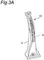
- Fig. 3A shows an example of a B pillar 12 (an example of the vehicle frame component) manufactured by processing the joint body 1 by hot stamping.
- the B pillar 12 including the blank material 2 and one sheet of reinforcing material 3 joined to the blank material 2 is produced by a method in which the reinforcing material 3 is welded only to a portion of the blank material 2 that needs to be reinforced so as to have the joint portion 5 shown in Fig. 1 and Fig. 2 and then molded integrally with the blank material 2 by hot stamping.
- Fig. 1 shows an example of a B pillar 12 (an example of the vehicle frame component) manufactured by processing the joint body 1 by hot stamping.
- the B pillar 12 including the blank material 2 and one sheet of reinforcing material 3 joined to the blank material 2 is produced by a method in which the reinforcing material 3 is welded only to a portion of the blank material 2 that needs to be reinforced so as to have the joint portion 5 shown in Fig. 1 and Fig. 2 and then molded integral
- 3B shows another example of the B pillar 12 manufactured by processing the joint body 1 by hot stamping.
- two reinforcing members 3 are joined to the blank material 2, and each of the reinforcing materials 3 is joined to a ridge line portion formed by hot stamping.
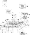
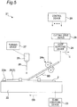
- Fig. 4 and Fig. 5 show a manufacturing apparatus 21 for the joint body 1 shown in Fig. 1 and Fig. 2 .
- the manufacturing apparatus 21 is also capable of manufacturing a joint body 1 that is different in structure of the joint portion 5 from the joint body 1 shown in Fig. 1 and Fig. 2 .
- the manufacturing apparatus 21 includes a table 22 on which the blank material 2 is detachably held by a fixture 22a.
- a blank conveying device 23 moves the table 22 and the blank material 2 held on the table 22 at a constant speed in a conveying direction CD opposite to the welding direction WD.
- the table 22 and the blank conveying device 23 serve as a conveying unit according to the present invention.
- the manufacturing apparatus 21 includes a hoop supplying device 24.
- the hoop supplying device 24 (supplying unit) includes a supplying roll pair 24a.
- the hoop supplying device 24 unwinds a hoop material 20 wound in a coil shape (that becomes the reinforcing material 3 when the joint body 1 is completed) with the supplying roll pair 24a to supply the hoop material 20 onto the blank material 2 held on the table 22. More specifically, the hoop supplying device 24 continuously supplies the hoop material 20 thus unwound in a supplying direction SD that coincides with the conveying direction CD of the blank material 2 while pressing the hoop material 20 against the blank material 2 obliquely from above.
- a supplying speed of the blank material 2 supplied by the hoop supplying device 24 is synchronized with a conveying speed of the blank material 2 conveyed by the blank conveying device 23. Further, it is also possible to supply not only a continuous body wound in a hoop shape or a coil shape, but also a band material cut in advance to a length of the reinforcing material 3 (second metal member).
- the manufacturing apparatus 21 includes a laser oscillation system 25.
- the laser oscillation system 25 includes components necessary for generating laser light, such as a laser oscillation element, a drive circuit, and an optical system.
- Laser light 26 emitted downward from the laser oscillation system 25 is projected onto an upper surface of the hoop material 20 at a position immediately before the hoop material 20 is pressed against the blank material 2 by the hoop supplying device 24.
- a symbol P0 denotes an irradiation position of the laser light 26.
- the laser oscillation system 25 does not move in horizontal and vertical directions.
- the manufacturing apparatus 21 includes a turning device 27 (irradiation direction changing unit).
- the turning device 27 periodically changes an irradiation direction of the laser light 26 emitted from the laser oscillation system 25.
- the turning device 27 periodically changes the irradiation direction of the laser light 26 to move a virtual irradiation position P1 along a closed figure (a circle as will be described later, according to the present embodiment).
- the blank conveying device 23, the hoop supplying device 24, and the turning device 27 serve as an irradiation position motion unit according to the present invention.
- the manufacturing apparatus 21 includes a cutting drive device 28.
- the cutting drive device 28 cuts the hoop material 20 by moving, after the hoop material 20 is welded to the blank material 2, the hoop supplying device 24 in the welding direction WD as indicated by an arrow C to apply tension to the hoop material 20.
- the band material cut in advance to the length of the reinforcing material 3 (second metal member) is used eliminates the need for the cutting drive device 28.
- a control device 29 controls, in a centralized manner, operations of various components of the manufacturing apparatus 21 including the blank conveying device 23, the hoop supplying device 24, the laser oscillation system 25, the turning device 27, and the cutting drive device 28.
- the irradiation direction of the laser light 26 emitted from the laser oscillation system 25 is periodically changed by the turning device 27. Further, the blank material 2 is moved in the conveying direction CD by the blank conveying device 23, and the hoop material 20 is continuously supplied from the hoop supplying device 24 in the supplying direction SD that coincides with the conveying direction CD. The movements of the blank material 2 and the hoop material 20 cause the laser oscillation system 25 to move relative to the blank material 2 and the hoop material 20 in the welding direction WD (opposite to the conveying direction CD and the supplying direction SD).
- the periodical change of the irradiation direction of the laser light 26 and the movement of the laser oscillation system 25 in the welding direction WD relative to the blank material 2 and the hoop material 20 change an irradiation position P0 of the laser light 26 on the upper surface of the hoop material 20.
- the main body 6 of the joint portion 5 including the first longitudinal portion 8, the second longitudinal portion 9, and the plurality of connecting portions 10 is obtained.
- Fig. 6A shows an irradiation pattern 31 of the laser light 26 according to the present embodiment.
- the irradiation pattern 31 is a closed figure along which the virtual irradiation position P1 of the laser light 26 moves assuming that the laser oscillation system 25 is not in motion in the welding direction WD relative to the blank material 2 and the hoop material 20.
- the irradiation pattern 31 according to the present embodiment has a circular shape.
- the irradiation pattern 31 is obtained by causing the turning device 27 to periodically change the irradiation direction of the laser light 26 emitted from the laser oscillation system 25.
- a symbol MD denotes a direction in which the virtual irradiation position P1 moves on the irradiation pattern 31 according to the present embodiment.
- Fig. 6B shows the main body 6 of the joint portion 5 obtained based on the irradiation pattern 31 having a circular shape shown in Fig. 6A .
- the shape of the main body 6 of the joint portion 5 is determined based on a geometric shape of the irradiation pattern 31, a speed Vw at which the laser oscillation system 25 moves in the welding direction WD relative to the blank material 2 and the hoop material 20, and a speed Vp1 at which the virtual irradiation position P1 moves on the irradiation pattern 31 to be described later.
- controlling the speed Vp1 at which the virtual irradiation position P1 moves on the irradiation pattern 31 allows a speed Vr at which the irradiation position P0 moves on the main body 6 of the joint portion 5 to be maintained within a favorable speed range. That is, the speed Vr at which the irradiation position P0 moves on the main body 6 of the joint portion 5 is made uniform. As a result, an excellent main body 6 of the joint portion 5 having a uniform depth, width, and the like can be obtained.
- the hoop supplying device 24 supplies the hoop material 20 unwound while pressing the hoop material 20 against the blank material 2 obliquely from above.
- the supplying direction SD of the hoop material 20 supplied from the hoop supplying device 24 coincides with the conveying direction CD of the blank material 2, and the supplying speed of the hoop material 20 coincides with the conveying speed of the blank material 2. That is, relative positions of the blank material 2 and the hoop material 20 do not move. Accordingly, the hoop material 20 can be fixed to the blank material 2 by the laser light 26 emitted from the laser oscillation system 25 without being temporarily fixed by a clamp using a fixture or the like.
- the entire surface of the hoop material 20 can be irradiated with the laser light 26. That is, the main body 6 of the joint portion 5 can be formed on the entire surface of the hoop material 20.
- the hoop material 20 that is continuous is cut.
- the virtual irradiation position P1 is repeatedly moved forward and backward in a direction orthogonal to the welding direction WD without interruption of the conveyance of the blank material 2 and the supply of the hoop material 20.
- the irradiation position P0 of the laser light 26 moves forward and backward in a zigzag-line shape at close intervals in a width direction of the hoop material 20 (the direction orthogonal to the welding direction WD), thereby forming the end portion 7 of the joint portion 5.
- the cutting drive device 28 moves the hoop supplying device 24 in the direction indicated by the arrow C (the direction that coincides with the welding direction WD) to apply tension to the hoop material 20.
- This tension cuts the hoop material 20 at the end portion 7 (see Fig. 7 ).
- a portion joined to the blank material 2 along the joint portion 5 becomes the reinforcing material 3.
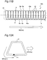
- Fig. 8A , Fig. 9A , Fig. 10A , Fig. 11A , Fig. 12A , Fig. 13A , Fig. 14A , Fig. 15A , and Fig. 16A show alternatives of the irradiation patterns 31.
- Fig. 8B , Fig. 9B , Fig. 10B , Fig. 11B , Fig. 12B , Fig. 13B , Fig. 14B , Fig. 15B , and Fig. 16A each show the main body 6 of the joint portion 5 obtained based on a corresponding one of the irradiation patterns 31.
- the same or similar elements as shown in Fig. 6A and Fig. 6B are denoted by the same symbols.
- the control of the speed Vp1 at which the virtual irradiation position P1 moves on the irradiation pattern 31 described with reference to Fig. 6A can be performed.
- the speed Vp1 is set equal to the reference speed Vp1_st for a region of the irradiation pattern 31 that extends approximately orthogonal to the welding direction WD.
- the irradiation pattern 31 shown in Fig. 8A has a circular shape, and a radius of the circle gradually increases.
- Fig. 8B in the main body 6 of the joint portion 5 obtained based on this irradiation pattern 31, intersecting portions 10a are formed where the welded portion 4 constituting adjacent connecting portions 10 intersects itself.
- a plurality of connecting portions 10 form a network structure.
- the radius of the circular irradiation pattern 31 can be gradually decreased. Further, even with the other irradiation patterns 31 shown in Fig. 9A , Fig. 10A , Fig. 11A , Fig. 12A , Fig. 13A , Fig. 14A , Fig. 15A , and Fig. 16A , a gradual increase or decrease in external dimension allows the entire surface of the reinforcing material 3 whose width varies in the longitudinal direction to be irradiated with the laser light 26.
- the irradiation patterns 31 shown in Fig. 9A has an elliptical shape whose major axis extends in the welding direction WD.
- the intersecting portions 10a are also formed where the welded portion 4 constituting adjacent connecting portions 10 intersects itself.
- a plurality of connecting portions 10 form a network structure.
- the irradiation pattern 31 shown in Fig. 10A has an elliptical shape whose minor axis extends in the welding direction WD.
- the irradiation pattern 31 also has an elliptical shape, but has a plurality of connecting portions 10 arranged in the welding direction WD at intervals closer than the intervals of the irradiation pattern 31 shown in Fig. 9A .
- the irradiation pattern 31 shown in Fig. 11A has a rectangular shape whose short sides extend in the welding direction WD.
- the first and second longitudinal portions 8, 9 have a shape similar to a geometric straight line as compared with the irradiation pattern 31 (circular) shown in Fig. 6A .
- each of the connecting portions 10 has a linear shape.
- the intersecting portions 10a are formed where the welded portion 4 constituting adjacent connecting portions 10 intersects itself. That is, even in this alternative, the plurality of connecting portions 10 form a network structure.
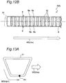
- the irradiation pattern 31 shown in Fig. 12A has an isosceles trapezoidal shape whose upper base and lower base extend in the welding direction WD.
- both the speed Vw at which the laser oscillation system 25 moves in the welding direction WD relative to the blank material 2 and the hoop material 20 and the speed Vp1 at which the virtual irradiation position P1 moves on the irradiation pattern 31 are appropriately set, thereby causing the first and second longitudinal portions 8, 9 to linearly extend in the welding direction WD.
- This further causes the connecting portions 10 to linearly extend in a direction approximately orthogonal to the welding direction WD.
- the welded portion 4 constituting the connecting portions 10 does not intersect itself, and the main body 6 of the joint portion 5 forms a ladder structure.
- the irradiation pattern 31 shown in Fig. 13A has an isosceles trapezoidal shape whose upper base and lower base extend in the welding direction WD, but is a pattern resulting from vertically inverting the irradiation pattern 31 shown in Fig. 12A .
- the first and second longitudinal portions 8, 9 each have a shape similar to a straight line as compared with the irradiation pattern 31 (circular) shown in Fig. 6A .
- each of the connecting portions 10 has a linear shape.
- the intersecting portions 10a are formed where the welded portion 4 constituting adjacent connecting portions 10 intersects itself. That is, even in this alternative, the plurality of connecting portions 10 form a network structure.
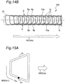
- the irradiation pattern 31 shown in Fig. 14A has an isosceles trapezoidal shape whose upper base and lower base extend in the direction orthogonal to the welding direction WD, and the upper base is oriented downstream in the welding direction WD.
- each of the connecting portions 10 has an approximately inverted C-shape.
- the intersecting portions 10a are formed where the welded portion 4 constituting adjacent connecting portions 10 intersects itself. That is, even in this alternative, the plurality of connecting portions 10 form a network structure.
- the irradiation pattern 31 shown in Fig. 15A has an isosceles trapezoidal shape whose upper base and lower base extend in the direction orthogonal to the welding direction WD, and the lower base is oriented downstream in the welding direction WD.
- each of the connecting portions 10 has an approximately C-shape.
- the intersecting portions 10a are formed where the welded portion 4 constituting adjacent connecting portions 10 intersects itself. That is, even in this alternative, the plurality of connecting portions 10 form a network structure.
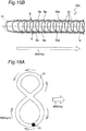
- the irradiation pattern 31 shown in Fig. 16A has a figure eight shape.
- each of the connecting portions 10 includes curved ends connected to the first and second longitudinal portions 8, 9, and a center portion has an approximately linear shape.
- the intersecting portions 10a are formed where the welded portion 4 constituting adjacent connecting portions 10 intersects itself. That is, even in this alternative, the plurality of connecting portions 10 form a network structure.
- An outer circumferential portion of the figure eight shape may have an elliptical shape.
- Fig. 17 shows a manufacturing apparatus 21 for a joint body according to the second embodiment of the present invention.
- the manufacturing apparatus 21 does not include the blank conveying device 23 (see Fig. 1 and Fig. 2 ), and the table 22 and the blank material 2 held on the table 22 are fixed.
- the manufacturing apparatus 21 includes a linear motion device 41 that linearly moves the laser oscillation system 25 in the welding direction WD (indicated by an arrow LMD1), and a linear motion device 42 that linearly moves, in a similar manner, the hoop supplying device 24 in the welding direction WD (indicated by an arrow LMD2).
- the linear motion devices 41, 42 serve as a synchronous motion unit according to the present invention.
- the hoop material 20 is continuously supplied by the hoop supplying device 24 from obliquely above the blank material 2.
- the laser oscillation system 25 and the hoop supplying device 24 move in the welding direction WD at a speed synchronized with the supplying speed of the hoop material 20.
- the irradiation direction of the laser light 26 emitted from the laser oscillation system 25 is changed by the turning device 27 such that the virtual irradiation position P1 moves along a specific irradiation pattern 31 (see Fig. 6A , Fig. 8A , Fig. 9A , Fig. 10A , Fig. 11A , Fig. 12A , Fig. 13A , Fig. 14A , Fig.
- the joint portion 5 is formed based on the irradiation pattern 31 (see Fig. 6B , Fig. 8B , Fig. 9B , Fig. 10B , Fig. 11B , Fig. 12B , Fig. 13B , Fig. 14B , Fig. 15B , and Fig. 16B ).
- the linear motion device 42 applies, after the formation of the end portion 7 of the joint portion 5, tension to the hoop material 20 to cut the hoop material 20.
- Fig. 18 shows a manufacturing apparatus 21 for a joint body according to the third embodiment of the present invention.
- the manufacturing apparatus 21 does not include the blank conveying device 23 (see Fig. 1 and Fig. 2 ), and the table 22 and the blank material 2 held on the table 22 are fixed. Further, the manufacturing apparatus 21 does not include the hoop supplying device 24 (see Fig. 1 and Fig. 2 ), and the reinforcing material 3 that has been cut out is temporarily fixed to the blank material 2 by a fixture 51. The reinforcing material 3 that has been cut out may be temporarily fixed to the blank material 2 by spot welding or laser spot welding.
- the laser oscillation system 25 is fixedly held by a robot arm 52a included in a robot 52 such that the laser light 26 is projected downward.
- the manufacturing apparatus 21 does not include the turning device 27 (see Fig. 1 and Fig. 2 ), and the irradiation direction of the laser light 26 is constant.
- the robot arm 52a moves the laser oscillation system 25 in two directions in a horizontal plane, that is, in an X direction and Y direction, such that the irradiation position P0 moves along a desired main body 6 of the joint portion 5 (see Fig. 6B , Fig. 8B , Fig. 9B , Fig. 10B , Fig. 11B , Fig. 12B , Fig. 13B , Fig. 14B , Fig. 15B , and Fig. 16B ).
- Fig. 19 shows the joint body 1 manufactured by the manufacturing apparatus 21 according to the present embodiment. Since the reinforcing material 3 that has been cut out is used rather than applying tension to the hoop material 20 to cut the hoop material 20, the joint portion 5 of the joint body 1 includes only the main body 6 without the end portion 7. Similarly, even when the joint body 1 is manufactured by the manufacturing apparatus 21 according to the first embodiment ( Fig. 4 and Fig. 5 ) and the manufacturing apparatus according to the second embodiment ( Fig. 17 ), a configuration where the reinforcing material 3 that has been cut out rather than the hoop material 20 that is continuously supplied is joined to the blank material 2 allows the joint portion 5 to include only the main body 6 without the end portion 7.
- Fig. 20 shows an alternative of the joint body 1.
- the joint portion 5 is formed, based on the irradiation pattern 31 shown in Fig. 12A , at both ends of the reinforcing material 3, and the joint portion 5 is formed, based on the irradiation pattern 31 shown in Fig. 9A , at portions other than both the ends of the reinforcing material 3.
- This causes the joint portion 5 to have, at both the ends of the reinforcing material 3, the same shape as shown in Fig. 12B and to have, at the portions other than both the ends of the reinforcing material 3, the same shape as shown in Fig. 9B .
- Fig. 12A is applied to both the ends of the reinforcing material 3 to provide the welded portion 4 at the corners of the reinforcing material 3, thereby further increasing the joint strength of the reinforcing material 3 to the blank material 2.
- At least any two of the irradiation patterns 31 shown in Fig. 6A , Fig. 8A , Fig. 9A , Fig. 10A , Fig. 11A , Fig. 12A , Fig. 13A , Fig. 14A , Fig. 15A , and Fig. 16A may be used in combination.
Landscapes
- Physics & Mathematics (AREA)
- Optics & Photonics (AREA)
- Engineering & Computer Science (AREA)
- Mechanical Engineering (AREA)
- Plasma & Fusion (AREA)
- Robotics (AREA)
- Laser Beam Processing (AREA)
- Body Structure For Vehicles (AREA)
- Non-Disconnectible Joints And Screw-Threaded Joints (AREA)
- Forging (AREA)
- Lining Or Joining Of Plastics Or The Like (AREA)
Abstract
Description
- The present invention relates to a manufacturing method for a joint body and a manufacturing apparatus for a joint body.
- Conventionally known is a technique for manufacturing an automobile frame member by press-molding a metal plate. For application of such an automobile frame member, there is a growing demand not only for metal plates with a constant thickness, but also for metal plates each reinforced by partially including a thickness-increased portion where the metal plate is increased in thickness.
-
Patent Documents -
- Patent Document 1:
JP 2001-507993 A - Patent Document 2:
JP 2016-064725 A - Herein, as disclosed in
Patent Documents - It is therefore an object of the present invention to provide a manufacturing method and manufacturing apparatus for a joint body having two metal members joined together by welding, an increase in joint strength between the two metal members being achieved by the manufacturing method and the manufacturing apparatus.
- Provided according to a first aspect of the present invention is a manufacturing method for a joint body having a first metal member and a second metal member joined together by causing a laser oscillation system to irradiate a surface of the second metal member placed on the first metal member with laser light to form a joint portion including a welded portion where the first metal member and the second metal member are joined together, the manufacturing method including continuously supplying the second metal member while pressing the second metal member against the first metal member, the second metal member being a hoop material, and causing the laser oscillation system to emit the laser light.
- The above configuration where the second metal member is continuously supplied while being pressed against the first metal member eliminates the need for clamping the second metal member to the first metal member and thus allows the entirety of the second metal member to be welded by laser. This in turn makes it possible to increase joint strength between the first metal member and the second metal member.
- Provided according to a second aspect of the present invention is a manufacturing apparatus for implementing the manufacturing method for a joint body according to the first aspect. Specifically, provided according to the second aspect of the present invention is a manufacturing apparatus for a joint body having a first metal member and a second metal member joined together by causing a laser oscillation system to irradiate a surface of the second metal member placed on the first metal member with laser light to form a joint portion including a welded portion where the first metal member and the second metal member are joined together, the manufacturing apparatus including a supplying unit configured to continuously supply the second metal member while pressing the second metal member against the first metal member, the second metal member being a hoop material.
- With the manufacturing method and the manufacturing apparatus according to the present invention, it is possible to manufacture a joint body having an increased joint strength between the first metal member and the second metal member constituting the joint body.
-
-
Fig. 1 is a perspective view of an example of a joint body manufactured by a manufacturing apparatus according to a first embodiment of the present invention. -
Fig. 2 is a plan view of the example of the joint body manufactured by the manufacturing apparatus according to the first embodiment of the present invention. -
Fig. 3A is a perspective view of an example of a B pillar manufactured by processing the joint body by hot stamping. -
Fig. 3B is a perspective view of another example of the B pillar manufactured by processing the joint body by hot stamping. -
Fig. 4 is a schematic perspective view of the manufacturing apparatus for the joint body according to the first embodiment of the present invention. -
Fig. 5 is a schematic side view of the manufacturing apparatus for the joint body according to the first embodiment of the present invention. -
Fig. 6A is a schematic plan view showing an example of an irradiation pattern of laser light. -
Fig. 6B is a schematic plan view showing an example of a joint portion obtained based on the irradiation pattern shown inFig. 6A . -
Fig. 7 is a schematic plan view for describing a cutting process. -
Fig. 8A is a schematic plan view showing a first alternative of the irradiation pattern of laser light. -
Fig. 8B is a schematic plan view showing an example of a joint portion obtained based on the irradiation pattern shown inFig. 8A . -
Fig. 9A is a schematic plan view showing a second alternative of the irradiation pattern of laser light. -
Fig. 9B is a schematic plan view showing an example of a joint portion obtained based on the irradiation pattern shown inFig. 9A . -
Fig. 10A is a schematic plan view showing a third alternative of the irradiation pattern of laser light. -
Fig. 10B is a schematic plan view showing an example of a joint portion obtained based on the irradiation pattern shown inFig. 10A . -
Fig. 11A is a schematic plan view showing a fourth alternative of the irradiation pattern of laser light. -
Fig. 11B is a schematic plan view showing an example of a joint portion obtained based on the irradiation pattern shown inFig. 11A . -
Fig. 12A is a schematic plan view showing a fifth alternative of the irradiation pattern of laser light. -
Fig. 12B is a schematic plan view showing an example of a joint portion obtained based on the irradiation pattern shown inFig. 12A . -
Fig. 13A is a schematic plan view showing a sixth alternative of the irradiation pattern of laser light. -
Fig. 13B is a schematic plan view showing an example of a joint portion obtained based on the irradiation pattern shown inFig. 13A . -
Fig. 14A is a schematic plan view showing a seventh alternative of the irradiation pattern of laser light. -
Fig. 14B is a schematic plan view showing an example of a joint portion obtained based on the irradiation pattern shown inFig. 14A . -
Fig. 15A is a schematic plan view showing an eighth alternative of the irradiation pattern of laser light. -
Fig. 15B is a schematic plan view showing an example of a joint portion obtained based on the irradiation pattern shown inFig. 15A . -
Fig. 16A is a schematic plan view showing a ninth alternative of the irradiation pattern of laser light. -
Fig. 16B is a schematic plan view showing an example of a joint portion obtained based on the irradiation pattern shown inFig. 16A . -
Fig. 17 is a schematic perspective view of a manufacturing apparatus for a joint body according to a second embodiment of the present invention. -
Fig. 18 is a schematic perspective view of a manufacturing apparatus for a joint body according to a third embodiment of the present invention. -
Fig. 19 is a perspective view of an example of the joint body manufactured by the manufacturing apparatus according to the third embodiment of the present invention. -
Fig. 20 is a plan view showing an alternative of the joint body. - A description will be given below of a first embodiment of the present invention with reference to
Fig. 1 to Fig. 16B . -
Fig. 1 and Fig. 2 show ajoint body 1 manufactured by a manufacturing apparatus (Fig. 4 andFig. 5 ) according to the first embodiment of the present invention. - The
joint body 1 shown inFig. 1 and Fig. 2 includes a blank material 2 (first metal member) that is an example of a steel plate and a reinforcing material 3 (second metal member) that is also an example of a steel plate. According to the present embodiment, the reinforcingmaterial 3 is narrower than theblank material 2. - The reinforcing
material 3 is placed on theblank material 2 and fixed to theblank material 2 by laser welding. Thejoint body 1 includes ajoint portion 5 formed by one streak of continuous welding mark or weldedportion 4, along which theblank material 2 and the reinforcingmaterial 3 are joined together. Thejoint portion 5 shown inFig. 1 and Fig. 2 is merely an example, and, as will be described later with reference toFig. 8A to Fig. 16B , the specific form of thejoint portion 5 includes various alternatives. - The
joint portion 5 includes amain body 6 and anend portion 7. - According to the present embodiment, the welded
portion 4 in themain body 6 of thejoint portion 5 has a curved shape having a periodic repetitive pattern and includes a firstlongitudinal portion 8, a secondlongitudinal portion 9, and a plurality of connectingportions 10 having a curved shape. In the firstlongitudinal portion 8, a plurality of intersectingportions 8a (first intersecting portions) where the weldedportion 4 intersects itself are arranged in one direction A (first direction) in plan view, and the firstlongitudinal portion 8 itself extends in the direction A. The direction A coincides with a welding direction (see a symbol WD inFig. 4 , for example) to be described later and a direction opposite to the welding direction. The secondlongitudinal portion 9 is located apart from the firstlongitudinal portion 8 in a direction B orthogonal to the direction A in plan view. In the secondlongitudinal portion 9, as with the firstlongitudinal portion 8, a plurality of intersectingportions 9a (second intersecting portions) where the weldedportion 4 intersects itself are arranged in the direction A in plan view, and the secondlongitudinal portion 9 itself extends in the direction A. The plurality of connectingportions 10 are arranged at intervals in the direction A, each of the connectingportions 10 extends in the direction B, and both ends of each of the connectingportions 10 are connected to the firstlongitudinal portion 8 and the secondlongitudinal portion 9. According to the present embodiment, the firstlongitudinal portion 8, the secondlongitudinal portion 9, and the plurality of connectingportions 10 form a ladder structure in plan view. - The
end portion 7 of thejoint portion 5 has a zigzag shape or a zigzag-line shape that extends forward and backward, at close intervals, between both ends in a width direction of the reinforcingmaterial 3. As will be described later with reference toFig. 19 , thejoint portion 5 may include only themain body 6 without theend portion 7. - In the
main body 6 of thejoint portion 5, the weldedportion 4 having a line shape continuously extends in two directions orthogonal to each other, that is, in both the directions A, B, in plan view. In other words, in themain body 6 of thejoint portion 5, the weldedportion 4 having a line shape is provided extending two-dimensionally, that is, in a planar form. Such a structure allows at least one streak of weldedportion 4 to be present in plan view within a region having a certain area in themain body 6 of thejoint portion 5. In particular, within small regions near the intersectingportions 8a of the firstlongitudinal portion 8 and the intersectingportions 9a of the secondlongitudinal portion 9, a plurality of streaks of weldedportions 4 are present. Themain body 6 of thejoint portion 5 having such a structure makes it possible to sufficiently increase the joint strength between theblank material 2 and the reinforcingmaterial 3. For example, when two members are joined together by spot welding, the welded portion includes a plurality of scattered spots. Further, the welded portion made even by laser welding may include one or a plurality of pairs of parallel straight lines, or may include a plurality of C-shaped portions arranged in a row and adjacent to each other. Compared to any of the above structures, themain body 6 of thejoint portion 5 in which the weldedportion 4 having a line shape continuously extends in both the directions A, B shown inFig. 1 and Fig. 2 makes it possible to join theblank material 2 and the reinforcingmaterial 3 with higher joint strength. - Since the
blank material 2 and the reinforcingmaterial 3 are joined together with sufficient joint strength, thejoint body 1 is suitable for processing by hot stamping, and it is thus possible to increase strength of a produced vehicle frame component against collision. For example,Fig. 3A shows an example of a B pillar 12 (an example of the vehicle frame component) manufactured by processing thejoint body 1 by hot stamping. In this example, theB pillar 12 including theblank material 2 and one sheet of reinforcingmaterial 3 joined to theblank material 2 is produced by a method in which the reinforcingmaterial 3 is welded only to a portion of theblank material 2 that needs to be reinforced so as to have thejoint portion 5 shown inFig. 1 and Fig. 2 and then molded integrally with theblank material 2 by hot stamping.Fig. 3B shows another example of theB pillar 12 manufactured by processing thejoint body 1 by hot stamping. In this example, two reinforcingmembers 3 are joined to theblank material 2, and each of the reinforcingmaterials 3 is joined to a ridge line portion formed by hot stamping. - In order to sufficiently increase the joint strength between the
blank material 2 and the reinforcingmaterial 3, it is preferable that, in themain body 6 of thejoint portion 5, at least one streak of weldedportion 4 passes through a square region whose side is 2 cm long, for example. -
Fig. 4 andFig. 5 show amanufacturing apparatus 21 for thejoint body 1 shown inFig. 1 and Fig. 2 . As will be described later with reference toFig. 8A to Fig. 16B , themanufacturing apparatus 21 is also capable of manufacturing ajoint body 1 that is different in structure of thejoint portion 5 from thejoint body 1 shown inFig. 1 and Fig. 2 . - The
manufacturing apparatus 21 includes a table 22 on which theblank material 2 is detachably held by afixture 22a. A blank conveyingdevice 23 moves the table 22 and theblank material 2 held on the table 22 at a constant speed in a conveying direction CD opposite to the welding direction WD. The table 22 and the blank conveyingdevice 23 serve as a conveying unit according to the present invention. - The
manufacturing apparatus 21 includes ahoop supplying device 24. The hoop supplying device 24 (supplying unit) includes a supplyingroll pair 24a. Thehoop supplying device 24 unwinds ahoop material 20 wound in a coil shape (that becomes the reinforcingmaterial 3 when thejoint body 1 is completed) with the supplyingroll pair 24a to supply thehoop material 20 onto theblank material 2 held on the table 22. More specifically, thehoop supplying device 24 continuously supplies thehoop material 20 thus unwound in a supplying direction SD that coincides with the conveying direction CD of theblank material 2 while pressing thehoop material 20 against theblank material 2 obliquely from above. A supplying speed of theblank material 2 supplied by thehoop supplying device 24 is synchronized with a conveying speed of theblank material 2 conveyed by the blank conveyingdevice 23. Further, it is also possible to supply not only a continuous body wound in a hoop shape or a coil shape, but also a band material cut in advance to a length of the reinforcing material 3 (second metal member). - The
manufacturing apparatus 21 includes alaser oscillation system 25. Thelaser oscillation system 25 includes components necessary for generating laser light, such as a laser oscillation element, a drive circuit, and an optical system.Laser light 26 emitted downward from thelaser oscillation system 25 is projected onto an upper surface of thehoop material 20 at a position immediately before thehoop material 20 is pressed against theblank material 2 by thehoop supplying device 24. InFig. 4 , a symbol P0 denotes an irradiation position of thelaser light 26. According to the present embodiment, thelaser oscillation system 25 does not move in horizontal and vertical directions. - The
manufacturing apparatus 21 includes a turning device 27 (irradiation direction changing unit). The turningdevice 27 periodically changes an irradiation direction of thelaser light 26 emitted from thelaser oscillation system 25. As will be described in detail later, assuming that thelaser oscillation system 25 is not in motion in the welding direction WD relative to theblank material 2 and thehoop material 20, the turningdevice 27 periodically changes the irradiation direction of thelaser light 26 to move a virtual irradiation position P1 along a closed figure (a circle as will be described later, according to the present embodiment). The blank conveyingdevice 23, thehoop supplying device 24, and theturning device 27 serve as an irradiation position motion unit according to the present invention. - The
manufacturing apparatus 21 includes a cuttingdrive device 28. As will be described in detail later, the cuttingdrive device 28 cuts thehoop material 20 by moving, after thehoop material 20 is welded to theblank material 2, thehoop supplying device 24 in the welding direction WD as indicated by an arrow C to apply tension to thehoop material 20. Note that, as described above, a configuration where the band material cut in advance to the length of the reinforcing material 3 (second metal member) is used eliminates the need for the cuttingdrive device 28. - A
control device 29 controls, in a centralized manner, operations of various components of themanufacturing apparatus 21 including the blank conveyingdevice 23, thehoop supplying device 24, thelaser oscillation system 25, the turningdevice 27, and the cuttingdrive device 28. - A description will be given below of an operation of the
manufacturing apparatus 21, that is, a manufacturing method for thejoint body 1 performed by themanufacturing apparatus 21. - The irradiation direction of the
laser light 26 emitted from thelaser oscillation system 25 is periodically changed by the turningdevice 27. Further, theblank material 2 is moved in the conveying direction CD by the blank conveyingdevice 23, and thehoop material 20 is continuously supplied from thehoop supplying device 24 in the supplying direction SD that coincides with the conveying direction CD. The movements of theblank material 2 and thehoop material 20 cause thelaser oscillation system 25 to move relative to theblank material 2 and thehoop material 20 in the welding direction WD (opposite to the conveying direction CD and the supplying direction SD). The periodical change of the irradiation direction of thelaser light 26 and the movement of thelaser oscillation system 25 in the welding direction WD relative to theblank material 2 and thehoop material 20 change an irradiation position P0 of thelaser light 26 on the upper surface of thehoop material 20. As a result, as described above, themain body 6 of thejoint portion 5 including the firstlongitudinal portion 8, the secondlongitudinal portion 9, and the plurality of connectingportions 10 is obtained. -
Fig. 6A shows anirradiation pattern 31 of thelaser light 26 according to the present embodiment. Theirradiation pattern 31 is a closed figure along which the virtual irradiation position P1 of thelaser light 26 moves assuming that thelaser oscillation system 25 is not in motion in the welding direction WD relative to theblank material 2 and thehoop material 20. Theirradiation pattern 31 according to the present embodiment has a circular shape. Theirradiation pattern 31 is obtained by causing theturning device 27 to periodically change the irradiation direction of thelaser light 26 emitted from thelaser oscillation system 25. InFig. 6A , a symbol MD denotes a direction in which the virtual irradiation position P1 moves on theirradiation pattern 31 according to the present embodiment. -
Fig. 6B shows themain body 6 of thejoint portion 5 obtained based on theirradiation pattern 31 having a circular shape shown inFig. 6A . In general, the shape of themain body 6 of thejoint portion 5 is determined based on a geometric shape of theirradiation pattern 31, a speed Vw at which thelaser oscillation system 25 moves in the welding direction WD relative to theblank material 2 and thehoop material 20, and a speed Vp1 at which the virtual irradiation position P1 moves on theirradiation pattern 31 to be described later. - According to the present embodiment, the speed Vp1 at which the virtual irradiation position P1 moves on the
irradiation pattern 31 is not constant. Specifically, for regions AR1, AR2 of theirradiation pattern 31 that extend approximately orthogonal to the welding direction WD, the speed Vp1 is set equal to a reference speed Vp1_st (Vp1 = Vp1_st). As the reference speed Vp1_st, for example, an average of the speed Vp1 at which the virtual irradiation position P1 moves on theirradiation pattern 31 can be used. For a region AR3 of theirradiation pattern 31 where the virtual irradiation position P1 moves in the direction approximately opposite to the welding direction WD, the speed Vp1 at which the virtual irradiation position P1 moves is set equal to a speed resulting from adding a correction α (α is a positive number) to the reference speed Vp1_st. (Vp1 = Vp1_st + α). On the other hand, for a region AR4 of theirradiation pattern 31 where the virtual irradiation position P1 moves approximately in the welding direction WD, the speed Vp1 at which the virtual irradiation position P1 moves is set equal to a speed resulting from subtracting the correction α from the reference speed Vp1_st (Vp1 = Vp1_st - α). As described above, controlling the speed Vp1 at which the virtual irradiation position P1 moves on theirradiation pattern 31 allows a speed Vr at which the irradiation position P0 moves on themain body 6 of thejoint portion 5 to be maintained within a favorable speed range. That is, the speed Vr at which the irradiation position P0 moves on themain body 6 of thejoint portion 5 is made uniform. As a result, an excellentmain body 6 of thejoint portion 5 having a uniform depth, width, and the like can be obtained. - The
hoop supplying device 24 supplies thehoop material 20 unwound while pressing thehoop material 20 against theblank material 2 obliquely from above. The supplying direction SD of thehoop material 20 supplied from thehoop supplying device 24 coincides with the conveying direction CD of theblank material 2, and the supplying speed of thehoop material 20 coincides with the conveying speed of theblank material 2. That is, relative positions of theblank material 2 and thehoop material 20 do not move. Accordingly, thehoop material 20 can be fixed to theblank material 2 by thelaser light 26 emitted from thelaser oscillation system 25 without being temporarily fixed by a clamp using a fixture or the like. Further, since this eliminates the need for a fixture or the like, the entire surface of thehoop material 20 can be irradiated with thelaser light 26. That is, themain body 6 of thejoint portion 5 can be formed on the entire surface of thehoop material 20. - After the
main body 6 of thejoint portion 5 having a necessary length is obtained, thehoop material 20 that is continuous is cut. When thehoop material 20 is cut, the virtual irradiation position P1 is repeatedly moved forward and backward in a direction orthogonal to the welding direction WD without interruption of the conveyance of theblank material 2 and the supply of thehoop material 20. As a result, the irradiation position P0 of thelaser light 26 moves forward and backward in a zigzag-line shape at close intervals in a width direction of the hoop material 20 (the direction orthogonal to the welding direction WD), thereby forming theend portion 7 of thejoint portion 5. Since the weldedportion 4 having a zigzag-line shape is densely located in theend portion 7, a molten pool before solidification reaches the vicinity of the lower surface of theblank material 2. Immediately after the irradiation with thelaser light 26 is stopped, the cuttingdrive device 28 moves thehoop supplying device 24 in the direction indicated by the arrow C (the direction that coincides with the welding direction WD) to apply tension to thehoop material 20. This tension cuts thehoop material 20 at the end portion 7 (seeFig. 7 ). Of thehoop material 20 thus cut, a portion joined to theblank material 2 along thejoint portion 5 becomes the reinforcingmaterial 3. - In order to continuously weld the reinforcing
material 3 using thehoop material 20, it is necessary to cut thehoop material 20 every time thejoint portion 5 is formed for each sheet of reinforcingmaterial 3. According to the present embodiment, since tension is applied to thehoop material 20 by the cuttingdrive device 28 to cut thehoop material 20 after the formation of theend portion 7 where the weldedportion 4 is densely located, it is not necessary to provide a mechanical cutting device such as a large cutter and in turn makes it possible to downsize themanufacturing apparatus 21. Note that means for applying tension to thehoop material 20 is not particularly limited to any specific means, and means such as a weight or a spring may be employed. -
Fig. 8A ,Fig. 9A ,Fig. 10A ,Fig. 11A ,Fig. 12A ,Fig. 13A ,Fig. 14A ,Fig. 15A , andFig. 16A show alternatives of theirradiation patterns 31.Fig. 8B ,Fig. 9B ,Fig. 10B ,Fig. 11B ,Fig. 12B ,Fig. 13B ,Fig. 14B ,Fig. 15B , andFig. 16B each show themain body 6 of thejoint portion 5 obtained based on a corresponding one of theirradiation patterns 31. In these drawings, the same or similar elements as shown inFig. 6A and Fig. 6B are denoted by the same symbols. - For any of these
alternative irradiation patterns 31, the control of the speed Vp1 at which the virtual irradiation position P1 moves on theirradiation pattern 31 described with reference toFig. 6A can be performed. When this control is performed, the speed Vp1 is set equal to the reference speed Vp1_st for a region of theirradiation pattern 31 that extends approximately orthogonal to the welding direction WD. Further, for a region of theirradiation pattern 31 where the virtual irradiation position P1 moves in the direction approximately opposite to the welding direction WD, the speed Vp1 is set equal to a speed resulting from adding the correction α to the reference speed Vp1_st (Vp1 = Vp1_st + α). Further, for a region of theirradiation pattern 31 where the virtual irradiation position P1 moves approximately in the welding direction WD, the speed Vp1 is set equal to a speed resulting from subtracting the correction α from the reference speed Vp1_st (Vp1 = Vp1_st - α). - The
irradiation pattern 31 shown inFig. 8A has a circular shape, and a radius of the circle gradually increases. As shown inFig. 8B , in themain body 6 of thejoint portion 5 obtained based on thisirradiation pattern 31, intersectingportions 10a are formed where the weldedportion 4 constituting adjacent connectingportions 10 intersects itself. In other words, in this alternative, a plurality of connectingportions 10 form a network structure. With thisirradiation pattern 31, even for the reinforcingmaterial 3 whose width varies in a longitudinal direction, it is possible to form the weldedportion 4 by irradiating the entire surface with thelaser light 26. In contrast to the case shown inFig. 8A , the radius of thecircular irradiation pattern 31 can be gradually decreased. Further, even with theother irradiation patterns 31 shown inFig. 9A ,Fig. 10A ,Fig. 11A ,Fig. 12A ,Fig. 13A ,Fig. 14A ,Fig. 15A , andFig. 16A , a gradual increase or decrease in external dimension allows the entire surface of the reinforcingmaterial 3 whose width varies in the longitudinal direction to be irradiated with thelaser light 26. - The
irradiation patterns 31 shown inFig. 9A has an elliptical shape whose major axis extends in the welding direction WD. As shown inFig. 9B , in themain body 6 of thejoint portion 5 obtained based on thisirradiation pattern 31, the intersectingportions 10a are also formed where the weldedportion 4 constituting adjacent connectingportions 10 intersects itself. In other words, in this alternative, a plurality of connectingportions 10 form a network structure. - The
irradiation pattern 31 shown inFig. 10A has an elliptical shape whose minor axis extends in the welding direction WD. As shown inFig. 10B , in themain body 6 of thejoint portion 5 obtained based on thisirradiation pattern 31, theirradiation pattern 31 also has an elliptical shape, but has a plurality of connectingportions 10 arranged in the welding direction WD at intervals closer than the intervals of theirradiation pattern 31 shown inFig. 9A . - The
irradiation pattern 31 shown inFig. 11A has a rectangular shape whose short sides extend in the welding direction WD. As shown inFig. 11B , in themain body 6 of thejoint portion 5 obtained based on thisirradiation pattern 31, for example, the first and secondlongitudinal portions Fig. 6A . Further, each of the connectingportions 10 has a linear shape. Furthermore, the intersectingportions 10a are formed where the weldedportion 4 constituting adjacent connectingportions 10 intersects itself. That is, even in this alternative, the plurality of connectingportions 10 form a network structure. - The
irradiation pattern 31 shown inFig. 12A has an isosceles trapezoidal shape whose upper base and lower base extend in the welding direction WD. As shown inFig. 12B , in this alternative, both the speed Vw at which thelaser oscillation system 25 moves in the welding direction WD relative to theblank material 2 and thehoop material 20 and the speed Vp1 at which the virtual irradiation position P1 moves on theirradiation pattern 31 are appropriately set, thereby causing the first and secondlongitudinal portions portions 10 to linearly extend in a direction approximately orthogonal to the welding direction WD. The weldedportion 4 constituting the connectingportions 10 does not intersect itself, and themain body 6 of thejoint portion 5 forms a ladder structure. - The
irradiation pattern 31 shown inFig. 13A has an isosceles trapezoidal shape whose upper base and lower base extend in the welding direction WD, but is a pattern resulting from vertically inverting theirradiation pattern 31 shown inFig. 12A . As shown inFig. 13B , in themain body 6 of thejoint portion 5 obtained based on thisirradiation pattern 31, for example, the first and secondlongitudinal portions Fig. 6A . Further, each of the connectingportions 10 has a linear shape. Furthermore, the intersectingportions 10a are formed where the weldedportion 4 constituting adjacent connectingportions 10 intersects itself. That is, even in this alternative, the plurality of connectingportions 10 form a network structure. - The
irradiation pattern 31 shown inFig. 14A has an isosceles trapezoidal shape whose upper base and lower base extend in the direction orthogonal to the welding direction WD, and the upper base is oriented downstream in the welding direction WD. As shown inFig. 14B , in themain body 6 of thejoint portion 5 obtained based on thisirradiation pattern 31, each of the connectingportions 10 has an approximately inverted C-shape. Further, the intersectingportions 10a are formed where the weldedportion 4 constituting adjacent connectingportions 10 intersects itself. That is, even in this alternative, the plurality of connectingportions 10 form a network structure. - The
irradiation pattern 31 shown inFig. 15A has an isosceles trapezoidal shape whose upper base and lower base extend in the direction orthogonal to the welding direction WD, and the lower base is oriented downstream in the welding direction WD. As shown inFig. 15B , in themain body 6 of thejoint portion 5 obtained based on thisirradiation pattern 31, each of the connectingportions 10 has an approximately C-shape. Further, the intersectingportions 10a are formed where the weldedportion 4 constituting adjacent connectingportions 10 intersects itself. That is, even in this alternative, the plurality of connectingportions 10 form a network structure. - The
irradiation pattern 31 shown inFig. 16A has a figure eight shape. As shown inFig. 16B , in themain body 6 of thejoint portion 5 obtained based on thisirradiation pattern 31, each of the connectingportions 10 includes curved ends connected to the first and secondlongitudinal portions portions 10a are formed where the weldedportion 4 constituting adjacent connectingportions 10 intersects itself. That is, even in this alternative, the plurality of connectingportions 10 form a network structure. An outer circumferential portion of the figure eight shape may have an elliptical shape. - Regarding the
manufacturing apparatus 21 according to second and third embodiments to be described below, a structure or function of which no specific description will be given is the same as the structure or function according to the first embodiment. In the drawings relating to these embodiments, the same or similar elements are denoted by the same symbols. -
Fig. 17 shows amanufacturing apparatus 21 for a joint body according to the second embodiment of the present invention. - The
manufacturing apparatus 21 does not include the blank conveying device 23 (seeFig. 1 and Fig. 2 ), and the table 22 and theblank material 2 held on the table 22 are fixed. Themanufacturing apparatus 21 includes alinear motion device 41 that linearly moves thelaser oscillation system 25 in the welding direction WD (indicated by an arrow LMD1), and alinear motion device 42 that linearly moves, in a similar manner, thehoop supplying device 24 in the welding direction WD (indicated by an arrow LMD2). Thelinear motion devices - The
hoop material 20 is continuously supplied by thehoop supplying device 24 from obliquely above theblank material 2. Thelaser oscillation system 25 and thehoop supplying device 24 move in the welding direction WD at a speed synchronized with the supplying speed of thehoop material 20. Further, the irradiation direction of thelaser light 26 emitted from thelaser oscillation system 25 is changed by the turningdevice 27 such that the virtual irradiation position P1 moves along a specific irradiation pattern 31 (seeFig. 6A ,Fig. 8A ,Fig. 9A ,Fig. 10A ,Fig. 11A ,Fig. 12A ,Fig. 13A ,Fig. 14A ,Fig. 15A , andFig. 16A ). Through the above processes, thejoint portion 5 is formed based on the irradiation pattern 31 (seeFig. 6B ,Fig. 8B ,Fig. 9B ,Fig. 10B ,Fig. 11B ,Fig. 12B ,Fig. 13B ,Fig. 14B ,Fig. 15B , andFig. 16B ). Note that thelinear motion device 42 applies, after the formation of theend portion 7 of thejoint portion 5, tension to thehoop material 20 to cut thehoop material 20. -
Fig. 18 shows amanufacturing apparatus 21 for a joint body according to the third embodiment of the present invention. - The
manufacturing apparatus 21 does not include the blank conveying device 23 (seeFig. 1 and Fig. 2 ), and the table 22 and theblank material 2 held on the table 22 are fixed. Further, themanufacturing apparatus 21 does not include the hoop supplying device 24 (seeFig. 1 and Fig. 2 ), and the reinforcingmaterial 3 that has been cut out is temporarily fixed to theblank material 2 by afixture 51. The reinforcingmaterial 3 that has been cut out may be temporarily fixed to theblank material 2 by spot welding or laser spot welding. Thelaser oscillation system 25 is fixedly held by arobot arm 52a included in arobot 52 such that thelaser light 26 is projected downward. In particular, according to the present embodiment, themanufacturing apparatus 21 does not include the turning device 27 (seeFig. 1 and Fig. 2 ), and the irradiation direction of thelaser light 26 is constant. - The
robot arm 52a moves thelaser oscillation system 25 in two directions in a horizontal plane, that is, in an X direction and Y direction, such that the irradiation position P0 moves along a desiredmain body 6 of the joint portion 5 (seeFig. 6B ,Fig. 8B ,Fig. 9B ,Fig. 10B ,Fig. 11B ,Fig. 12B ,Fig. 13B ,Fig. 14B ,Fig. 15B , andFig. 16B ). -
Fig. 19 shows thejoint body 1 manufactured by themanufacturing apparatus 21 according to the present embodiment. Since the reinforcingmaterial 3 that has been cut out is used rather than applying tension to thehoop material 20 to cut thehoop material 20, thejoint portion 5 of thejoint body 1 includes only themain body 6 without theend portion 7. Similarly, even when thejoint body 1 is manufactured by themanufacturing apparatus 21 according to the first embodiment (Fig. 4 andFig. 5 ) and the manufacturing apparatus according to the second embodiment (Fig. 17 ), a configuration where the reinforcingmaterial 3 that has been cut out rather than thehoop material 20 that is continuously supplied is joined to theblank material 2 allows thejoint portion 5 to include only themain body 6 without theend portion 7. -
Fig. 20 shows an alternative of thejoint body 1. In this alternative, thejoint portion 5 is formed, based on theirradiation pattern 31 shown inFig. 12A , at both ends of the reinforcingmaterial 3, and thejoint portion 5 is formed, based on theirradiation pattern 31 shown inFig. 9A , at portions other than both the ends of the reinforcingmaterial 3. This causes thejoint portion 5 to have, at both the ends of the reinforcingmaterial 3, the same shape as shown inFig. 12B and to have, at the portions other than both the ends of the reinforcingmaterial 3, the same shape as shown inFig. 9B . Theirradiation pattern 31 shown inFig. 12A is applied to both the ends of the reinforcingmaterial 3 to provide the weldedportion 4 at the corners of the reinforcingmaterial 3, thereby further increasing the joint strength of the reinforcingmaterial 3 to theblank material 2. At least any two of theirradiation patterns 31 shown inFig. 6A ,Fig. 8A ,Fig. 9A ,Fig. 10A ,Fig. 11A ,Fig. 12A ,Fig. 13A ,Fig. 14A ,Fig. 15A , andFig. 16A may be used in combination. -
- 1
- Joint body
- 2
- Blank material (first metal member)
- 3
- Reinforcing material (second metal member)
- 4
- Welded portion
- 5
- Joint portion
- 6
- Main body
- 7
- End portion
- 8
- First longitudinal portion
- 8a
- Intersecting portion
- 9
- Second longitudinal portion
- 9a
- Intersecting portion
- 10
- Connecting portion
- 10a
- Intersecting portion
- 12
- B pillar
- 20
- Hoop material (second metal member)
- 21
- Manufacturing apparatus
- 22
- Table
- 22a
- Fixture
- 23
- Blank conveying device
- 24
- Hoop supplying device (supplying unit)
- 24a
- Supplying roll pair
- 25
- Laser oscillation system
- 26
- Laser light
- 27
- Turning device (irradiation direction changing unit)
- 28
- Cutting drive device
- 29
- Control device
- 31
- Irradiation pattern
- 41, 42
- Linear motion device
- 51
- Fixture
- 52
- Robot
- 52a
- Robot arm
- P0
- Irradiation position
- P1
- Virtual irradiation position
- A
- Direction (first direction)
- B
- Direction (second direction)
- C
- Direction
- WD
- Welding direction
- CD
- Conveying direction
- SD
- Supplying direction
- MD
- Motion direction
- LMD1
- Linear motion direction
- LMD2
- Linear motion direction
- AR1, AR2, AR3, AR4
- Region
Claims (9)
- A manufacturing method for a joint body having a first metal member and a second metal member joined together by causing a laser oscillation system to irradiate a surface of the second metal member placed on the first metal member with laser light to form a joint portion including a welded portion where the first metal member and the second metal member are joined together, the manufacturing method comprising:continuously supplying the second metal member while pressing the second metal member against the first metal member, the second metal member being a hoop material; andcausing the laser oscillation system to emit the laser light.
- The manufacturing method for a joint body according to claim 1, wherein
an irradiation position of the laser light is moved to cause the joint portion to include
a first longitudinal portion extending in a first direction, the first longitudinal portion having first intersecting portions arranged in the first direction, the welded portion intersecting itself at the first intersecting portions,
a second longitudinal portion located apart from the first longitudinal portion in a second direction intersecting the first direction and extending in the first direction, the second longitudinal portion having second intersecting portions arranged in the first direction, the welded portion intersecting itself at the second intersecting portions, and
a plurality of connecting portions arranged in the first direction, each extending in the second direction and connecting the first longitudinal portion and the second longitudinal portion. - The manufacturing method for a joint body according to claim 2, wherein
assuming that the laser oscillation system is not in motion in a welding direction relative to the first and second metal members, an irradiation direction of the laser light is periodically changed, and the laser oscillation system is moved in the welding direction relative to the first and second metal members to move the irradiation position along a closed figure. - The manufacturing method for a joint body according to claim 3, wherein
the first metal member is conveyed in a conveying direction opposite to the welding direction, and the second metal member is continuously supplied in a supplying direction that coincides with the conveying direction, and
with a position of the laser oscillation system fixed, the irradiation direction of the laser light emitted from the laser oscillation system is periodically changed to move the irradiation position along the closed figure. - The manufacturing method for a joint body according to claim 3, wherein
a position of the first metal member is fixed,
the second metal member, a source of supply of the second metal member, and the laser oscillation system are moved in the welding direction at a speed synchronized with a supplying speed of the second metal member, and
the irradiation direction of the laser light emitted from the laser oscillation system is periodically changed to move the irradiation position along the closed figure. - A manufacturing apparatus for a joint body having a first metal member and a second metal member joined together by causing a laser oscillation system to irradiate a surface of the second metal member placed on the first metal member with laser light to form a joint portion including a welded portion where the first metal member and the second metal member are joined together, the manufacturing apparatus comprising a supplying unit configured to continuously supply the second metal member while pressing the second metal member against the first metal member, the second metal member being a hoop material.
- The manufacturing apparatus for a joint body according to claim 6 further comprising an irradiation position motion unit configured to move an irradiation position of the laser light to cause the joint portion to include
a first longitudinal portion extending in a first direction, the first longitudinal portion having first intersecting portions arranged in the first direction, the welded portion intersecting itself at the first intersecting portions,
a second longitudinal portion located apart from the first longitudinal portion in a second direction intersecting the first direction and extending in the first direction, the second longitudinal portion having second intersecting portions arranged in the first direction, the welded portion intersecting itself at the second intersecting portions, and
a plurality of connecting portions arranged in the first direction, each extending in the second direction and connecting the first longitudinal portion and the second longitudinal portion, wherein
assuming that the laser oscillation system is not in motion in a welding direction relative to the first and second metal members, the irradiation position motion unit periodically changes an irradiation direction of the laser light and moves the laser oscillation system in the welding direction relative to the first and second metal members to move the irradiation position along a closed figure. - The manufacturing apparatus for a joint body according to claim 7, wherein
a position of the laser oscillation system is fixed, and
the irradiation position motion unit includes
the supplying unit,
a conveying unit configured to convey the first metal member in a conveying direction opposite to the welding direction, and
an irradiation direction changing unit configured to periodically change the irradiation direction of the laser light emitted from the laser oscillation system to move the irradiation position along the closed figure, wherein
the supplying unit continuously supplies the second metal member in a supplying direction that coincides with the conveying direction. - The manufacturing apparatus for a joint body according to claim 7, wherein
a position of the first metal member is fixed, and
the irradiation position motion unit includes
the supplying unit,
a synchronous motion unit configured to move the supplying unit and the laser oscillation system in the welding direction at a speed synchronized with a supplying speed of the second metal member, and
an irradiation direction changing unit configured to periodically change the irradiation direction of the laser light emitted from the laser oscillation system to move the irradiation position along the closed figure.
Applications Claiming Priority (2)
| Application Number | Priority Date | Filing Date | Title |
|---|---|---|---|
| JP2017167224A JP6948888B2 (en) | 2017-08-31 | 2017-08-31 | Joint manufacturing method and joint manufacturing equipment |
| PCT/JP2018/029206 WO2019044380A1 (en) | 2017-08-31 | 2018-08-03 | Method for manufacturing joined body and device for manufacturing joined body |
Publications (3)
| Publication Number | Publication Date |
|---|---|
| EP3677374A1 true EP3677374A1 (en) | 2020-07-08 |
| EP3677374A4 EP3677374A4 (en) | 2021-06-09 |
| EP3677374B1 EP3677374B1 (en) | 2023-01-04 |
Family
ID=65526224
Family Applications (1)
| Application Number | Title | Priority Date | Filing Date |
|---|---|---|---|
| EP18850541.6A Active EP3677374B1 (en) | 2017-08-31 | 2018-08-03 | Manufacturing method for join body and manufacturing apparatus for join body |
Country Status (6)
| Country | Link |
|---|---|
| US (1) | US11465239B2 (en) |
| EP (1) | EP3677374B1 (en) |
| JP (1) | JP6948888B2 (en) |
| CN (1) | CN111050982B (en) |
| ES (1) | ES2936611T3 (en) |
| WO (1) | WO2019044380A1 (en) |
Families Citing this family (6)
| Publication number | Priority date | Publication date | Assignee | Title |
|---|---|---|---|---|
| DE102017211982B4 (en) * | 2017-07-13 | 2019-04-18 | Trumpf Laser- Und Systemtechnik Gmbh | Method and device for joining at least two workpieces |
| JP7317429B2 (en) * | 2019-12-19 | 2023-07-31 | エルジー エナジー ソリューション リミテッド | Battery module and manufacturing method thereof |
| WO2021230070A1 (en) * | 2020-05-14 | 2021-11-18 | パナソニックIpマネジメント株式会社 | Laser welding method and laser welding device |
| WO2022075211A1 (en) * | 2020-10-05 | 2022-04-14 | パナソニックIpマネジメント株式会社 | Laser welding method and laser welding device |
| JP7818793B2 (en) * | 2021-06-03 | 2026-02-24 | 株式会社トヨコー | Laser irradiation device, laser irradiation method, and laser irradiation-treated surface |
| JP7660451B2 (en) * | 2021-07-07 | 2025-04-11 | 川崎重工業株式会社 | Laser Welding Method |
Family Cites Families (14)
| Publication number | Priority date | Publication date | Assignee | Title |
|---|---|---|---|---|
| US4042801A (en) * | 1974-08-31 | 1977-08-16 | British Aircraft Corporation Limited | Electron beam apparatus |
| JP3238077B2 (en) | 1996-08-28 | 2001-12-10 | 新日本製鐵株式会社 | Lap laser welding method for galvanized steel sheet |
| US6977355B2 (en) | 1997-01-14 | 2005-12-20 | Walter Duley | Tailored blank |
| GB9700652D0 (en) | 1997-01-14 | 1997-03-05 | Powerlasers Ltd | Composite tailored blank |
| JP2002160020A (en) * | 2000-11-28 | 2002-06-04 | Sumitomo Metal Ind Ltd | Bonded metal strip for automobile body and method of manufacturing the same |
| CN1159121C (en) * | 2002-09-25 | 2004-07-28 | 江苏大学 | A rapid molding method and device based on laser shock wave technology |
| JP2006062460A (en) * | 2004-08-25 | 2006-03-09 | Nissan Motor Co Ltd | Blank material |
| JP4822737B2 (en) * | 2005-04-22 | 2011-11-24 | ミヤチテクノス株式会社 | Laser welding method and laser welding apparatus |
| JP4947146B2 (en) * | 2007-06-28 | 2012-06-06 | パナソニック株式会社 | Laser processing equipment |
| JP5353087B2 (en) | 2008-06-24 | 2013-11-27 | スズキ株式会社 | Laser welding gap control device |
| CN103056533B (en) * | 2012-12-20 | 2015-04-15 | 华中科技大学 | Oscillatory scanning laser beam-electric arc hybrid welding method and system |
| US10543549B2 (en) * | 2013-07-16 | 2020-01-28 | Illinois Tool Works Inc. | Additive manufacturing system for joining and surface overlay |
| US10471540B2 (en) | 2014-02-25 | 2019-11-12 | Panasonic Intellectual Property Management Co., Ltd. | Laser welding method |
| JP6049146B2 (en) | 2014-09-24 | 2016-12-21 | 富士重工業株式会社 | Body frame structure |
-
2017
- 2017-08-31 JP JP2017167224A patent/JP6948888B2/en active Active
-
2018
- 2018-08-03 ES ES18850541T patent/ES2936611T3/en active Active
- 2018-08-03 EP EP18850541.6A patent/EP3677374B1/en active Active
- 2018-08-03 WO PCT/JP2018/029206 patent/WO2019044380A1/en not_active Ceased
- 2018-08-03 US US16/636,172 patent/US11465239B2/en active Active
- 2018-08-03 CN CN201880056574.7A patent/CN111050982B/en active Active
Also Published As
| Publication number | Publication date |
|---|---|
| ES2936611T3 (en) | 2023-03-21 |
| CN111050982A (en) | 2020-04-21 |
| US20200376598A1 (en) | 2020-12-03 |
| EP3677374B1 (en) | 2023-01-04 |
| CN111050982B (en) | 2022-04-29 |
| JP2019042758A (en) | 2019-03-22 |
| EP3677374A4 (en) | 2021-06-09 |
| JP6948888B2 (en) | 2021-10-13 |
| WO2019044380A1 (en) | 2019-03-07 |
| US11465239B2 (en) | 2022-10-11 |
Similar Documents
| Publication | Publication Date | Title |
|---|---|---|
| US11465239B2 (en) | Manufacturing method for joint body and manufacturing apparatus for joint body | |
| EP3677377B1 (en) | Method and device for manufacturing joined body | |
| EP3674030A1 (en) | Tack welding method and tack welding device | |
| WO2013167240A1 (en) | Method and device for laser-joining at least two workpieces using a vapor capillary and oscillation of the laser beam | |
| EP3677376B1 (en) | Method of and apparatus for manufacturing a joined body, and joined body | |
| KR101266256B1 (en) | A laser welding method | |
| JP2016150370A (en) | Pretreatment method of work-piece using laser beam and laser beam machine | |
| EP3677375B1 (en) | Joint body, manufacturing method for joint body, and manufacturing apparatus for joint body | |
| JP6211340B2 (en) | Welding apparatus and welding method | |
| CN110997219A (en) | Hybrid welding method and hybrid welding device | |
| JP6741547B2 (en) | Welding method | |
| KR102520937B1 (en) | Method for Quartz Welding with Laser | |
| WO2019044387A1 (en) | Joined body, and method and apparatus for manufacturing joined body | |
| KR20150112509A (en) | Welding apparatus |
Legal Events
| Date | Code | Title | Description |
|---|---|---|---|
| STAA | Information on the status of an ep patent application or granted ep patent |
Free format text: STATUS: THE INTERNATIONAL PUBLICATION HAS BEEN MADE |
|
| PUAI | Public reference made under article 153(3) epc to a published international application that has entered the european phase |
Free format text: ORIGINAL CODE: 0009012 |
|
| STAA | Information on the status of an ep patent application or granted ep patent |
Free format text: STATUS: REQUEST FOR EXAMINATION WAS MADE |
|
| 17P | Request for examination filed |
Effective date: 20200206 |
|
| AK | Designated contracting states |
Kind code of ref document: A1 Designated state(s): AL AT BE BG CH CY CZ DE DK EE ES FI FR GB GR HR HU IE IS IT LI LT LU LV MC MK MT NL NO PL PT RO RS SE SI SK SM TR |
|
| AX | Request for extension of the european patent |
Extension state: BA ME |
|
| DAV | Request for validation of the european patent (deleted) | ||
| DAX | Request for extension of the european patent (deleted) | ||
| A4 | Supplementary search report drawn up and despatched |
Effective date: 20210510 |
|
| RIC1 | Information provided on ipc code assigned before grant |
Ipc: B23K 26/08 20140101AFI20210503BHEP Ipc: B23K 26/21 20140101ALI20210503BHEP Ipc: B23K 26/082 20140101ALI20210503BHEP Ipc: B23K 26/244 20140101ALI20210503BHEP Ipc: B23K 26/26 20140101ALI20210503BHEP Ipc: B23K 37/04 20060101ALI20210503BHEP Ipc: B62D 25/02 20060101ALI20210503BHEP Ipc: B23K 101/00 20060101ALN20210503BHEP Ipc: B23K 101/16 20060101ALN20210503BHEP Ipc: B23K 101/18 20060101ALN20210503BHEP Ipc: B23K 103/04 20060101ALN20210503BHEP |
|
| RIC1 | Information provided on ipc code assigned before grant |
Ipc: B23K 103/04 20060101ALN20220525BHEP Ipc: B23K 101/18 20060101ALN20220525BHEP Ipc: B23K 101/16 20060101ALN20220525BHEP Ipc: B23K 101/00 20060101ALN20220525BHEP Ipc: B62D 25/02 20060101ALI20220525BHEP Ipc: B23K 37/04 20060101ALI20220525BHEP Ipc: B23K 26/26 20140101ALI20220525BHEP Ipc: B23K 26/244 20140101ALI20220525BHEP Ipc: B23K 26/082 20140101ALI20220525BHEP Ipc: B23K 26/21 20140101ALI20220525BHEP Ipc: B23K 26/08 20140101AFI20220525BHEP |
|
| REG | Reference to a national code |
Ref country code: DE Ref legal event code: R079 Ref document number: 602018045132 Country of ref document: DE Free format text: PREVIOUS MAIN CLASS: B23K0026280000 Ipc: B23K0026080000 |
|
| RIC1 | Information provided on ipc code assigned before grant |
Ipc: B23K 103/04 20060101ALN20220527BHEP Ipc: B23K 101/18 20060101ALN20220527BHEP Ipc: B23K 101/16 20060101ALN20220527BHEP Ipc: B23K 101/00 20060101ALN20220527BHEP Ipc: B62D 25/02 20060101ALI20220527BHEP Ipc: B23K 37/04 20060101ALI20220527BHEP Ipc: B23K 26/26 20140101ALI20220527BHEP Ipc: B23K 26/244 20140101ALI20220527BHEP Ipc: B23K 26/082 20140101ALI20220527BHEP Ipc: B23K 26/21 20140101ALI20220527BHEP Ipc: B23K 26/08 20140101AFI20220527BHEP |
|
| GRAP | Despatch of communication of intention to grant a patent |
Free format text: ORIGINAL CODE: EPIDOSNIGR1 |
|
| STAA | Information on the status of an ep patent application or granted ep patent |
Free format text: STATUS: GRANT OF PATENT IS INTENDED |
|
| RIC1 | Information provided on ipc code assigned before grant |
Ipc: B23K 103/04 20060101ALN20220623BHEP Ipc: B23K 101/18 20060101ALN20220623BHEP Ipc: B23K 101/16 20060101ALN20220623BHEP Ipc: B23K 101/00 20060101ALN20220623BHEP Ipc: B62D 25/02 20060101ALI20220623BHEP Ipc: B23K 37/04 20060101ALI20220623BHEP Ipc: B23K 26/26 20140101ALI20220623BHEP Ipc: B23K 26/244 20140101ALI20220623BHEP Ipc: B23K 26/082 20140101ALI20220623BHEP Ipc: B23K 26/21 20140101ALI20220623BHEP Ipc: B23K 26/08 20140101AFI20220623BHEP |
|
| RIC1 | Information provided on ipc code assigned before grant |
Ipc: B23K 103/04 20060101ALN20220630BHEP Ipc: B23K 101/18 20060101ALN20220630BHEP Ipc: B23K 101/16 20060101ALN20220630BHEP Ipc: B23K 101/00 20060101ALN20220630BHEP Ipc: B62D 25/02 20060101ALI20220630BHEP Ipc: B23K 37/04 20060101ALI20220630BHEP Ipc: B23K 26/26 20140101ALI20220630BHEP Ipc: B23K 26/244 20140101ALI20220630BHEP Ipc: B23K 26/082 20140101ALI20220630BHEP Ipc: B23K 26/21 20140101ALI20220630BHEP Ipc: B23K 26/08 20140101AFI20220630BHEP |
|
| INTG | Intention to grant announced |
Effective date: 20220722 |
|
| GRAS | Grant fee paid |
Free format text: ORIGINAL CODE: EPIDOSNIGR3 |
|
| GRAA | (expected) grant |
Free format text: ORIGINAL CODE: 0009210 |
|
| STAA | Information on the status of an ep patent application or granted ep patent |
Free format text: STATUS: THE PATENT HAS BEEN GRANTED |
|
| AK | Designated contracting states |
Kind code of ref document: B1 Designated state(s): AL AT BE BG CH CY CZ DE DK EE ES FI FR GB GR HR HU IE IS IT LI LT LU LV MC MK MT NL NO PL PT RO RS SE SI SK SM TR |
|
| REG | Reference to a national code |
Ref country code: GB Ref legal event code: FG4D |
|
| REG | Reference to a national code |
Ref country code: CH Ref legal event code: EP |
|
| REG | Reference to a national code |
Ref country code: AT Ref legal event code: REF Ref document number: 1541583 Country of ref document: AT Kind code of ref document: T Effective date: 20230115 |
|
| REG | Reference to a national code |
Ref country code: DE Ref legal event code: R096 Ref document number: 602018045132 Country of ref document: DE |
|
| REG | Reference to a national code |
Ref country code: IE Ref legal event code: FG4D |
|
| REG | Reference to a national code |
Ref country code: SE Ref legal event code: TRGR |
|
| REG | Reference to a national code |
Ref country code: ES Ref legal event code: FG2A Ref document number: 2936611 Country of ref document: ES Kind code of ref document: T3 Effective date: 20230321 |
|
| REG | Reference to a national code |
Ref country code: SK Ref legal event code: T3 Ref document number: E 41171 Country of ref document: SK |
|
| REG | Reference to a national code |
Ref country code: LT Ref legal event code: MG9D |
|
| REG | Reference to a national code |
Ref country code: NL Ref legal event code: MP Effective date: 20230104 |
|
| P01 | Opt-out of the competence of the unified patent court (upc) registered |
Effective date: 20230523 |
|
| PG25 | Lapsed in a contracting state [announced via postgrant information from national office to epo] |
Ref country code: NL Free format text: LAPSE BECAUSE OF FAILURE TO SUBMIT A TRANSLATION OF THE DESCRIPTION OR TO PAY THE FEE WITHIN THE PRESCRIBED TIME-LIMIT Effective date: 20230104 |
|
| PG25 | Lapsed in a contracting state [announced via postgrant information from national office to epo] |
Ref country code: RS Free format text: LAPSE BECAUSE OF FAILURE TO SUBMIT A TRANSLATION OF THE DESCRIPTION OR TO PAY THE FEE WITHIN THE PRESCRIBED TIME-LIMIT Effective date: 20230104 Ref country code: PT Free format text: LAPSE BECAUSE OF FAILURE TO SUBMIT A TRANSLATION OF THE DESCRIPTION OR TO PAY THE FEE WITHIN THE PRESCRIBED TIME-LIMIT Effective date: 20230504 Ref country code: NO Free format text: LAPSE BECAUSE OF FAILURE TO SUBMIT A TRANSLATION OF THE DESCRIPTION OR TO PAY THE FEE WITHIN THE PRESCRIBED TIME-LIMIT Effective date: 20230404 Ref country code: LV Free format text: LAPSE BECAUSE OF FAILURE TO SUBMIT A TRANSLATION OF THE DESCRIPTION OR TO PAY THE FEE WITHIN THE PRESCRIBED TIME-LIMIT Effective date: 20230104 Ref country code: LT Free format text: LAPSE BECAUSE OF FAILURE TO SUBMIT A TRANSLATION OF THE DESCRIPTION OR TO PAY THE FEE WITHIN THE PRESCRIBED TIME-LIMIT Effective date: 20230104 Ref country code: HR Free format text: LAPSE BECAUSE OF FAILURE TO SUBMIT A TRANSLATION OF THE DESCRIPTION OR TO PAY THE FEE WITHIN THE PRESCRIBED TIME-LIMIT Effective date: 20230104 |
|
| PG25 | Lapsed in a contracting state [announced via postgrant information from national office to epo] |
Ref country code: PL Free format text: LAPSE BECAUSE OF FAILURE TO SUBMIT A TRANSLATION OF THE DESCRIPTION OR TO PAY THE FEE WITHIN THE PRESCRIBED TIME-LIMIT Effective date: 20230104 Ref country code: IS Free format text: LAPSE BECAUSE OF FAILURE TO SUBMIT A TRANSLATION OF THE DESCRIPTION OR TO PAY THE FEE WITHIN THE PRESCRIBED TIME-LIMIT Effective date: 20230504 Ref country code: GR Free format text: LAPSE BECAUSE OF FAILURE TO SUBMIT A TRANSLATION OF THE DESCRIPTION OR TO PAY THE FEE WITHIN THE PRESCRIBED TIME-LIMIT Effective date: 20230405 Ref country code: FI Free format text: LAPSE BECAUSE OF FAILURE TO SUBMIT A TRANSLATION OF THE DESCRIPTION OR TO PAY THE FEE WITHIN THE PRESCRIBED TIME-LIMIT Effective date: 20230104 |
|
| REG | Reference to a national code |
Ref country code: DE Ref legal event code: R097 Ref document number: 602018045132 Country of ref document: DE |
|
| PG25 | Lapsed in a contracting state [announced via postgrant information from national office to epo] |
Ref country code: SM Free format text: LAPSE BECAUSE OF FAILURE TO SUBMIT A TRANSLATION OF THE DESCRIPTION OR TO PAY THE FEE WITHIN THE PRESCRIBED TIME-LIMIT Effective date: 20230104 Ref country code: RO Free format text: LAPSE BECAUSE OF FAILURE TO SUBMIT A TRANSLATION OF THE DESCRIPTION OR TO PAY THE FEE WITHIN THE PRESCRIBED TIME-LIMIT Effective date: 20230104 Ref country code: EE Free format text: LAPSE BECAUSE OF FAILURE TO SUBMIT A TRANSLATION OF THE DESCRIPTION OR TO PAY THE FEE WITHIN THE PRESCRIBED TIME-LIMIT Effective date: 20230104 Ref country code: DK Free format text: LAPSE BECAUSE OF FAILURE TO SUBMIT A TRANSLATION OF THE DESCRIPTION OR TO PAY THE FEE WITHIN THE PRESCRIBED TIME-LIMIT Effective date: 20230104 |
|
| PLBE | No opposition filed within time limit |
Free format text: ORIGINAL CODE: 0009261 |
|
| STAA | Information on the status of an ep patent application or granted ep patent |
Free format text: STATUS: NO OPPOSITION FILED WITHIN TIME LIMIT |
|
| 26N | No opposition filed |
Effective date: 20231005 |
|
| REG | Reference to a national code |
Ref country code: AT Ref legal event code: UEP Ref document number: 1541583 Country of ref document: AT Kind code of ref document: T Effective date: 20230104 |
|
| PG25 | Lapsed in a contracting state [announced via postgrant information from national office to epo] |
Ref country code: SI Free format text: LAPSE BECAUSE OF FAILURE TO SUBMIT A TRANSLATION OF THE DESCRIPTION OR TO PAY THE FEE WITHIN THE PRESCRIBED TIME-LIMIT Effective date: 20230104 |
|
| PG25 | Lapsed in a contracting state [announced via postgrant information from national office to epo] |
Ref country code: MC Free format text: LAPSE BECAUSE OF FAILURE TO SUBMIT A TRANSLATION OF THE DESCRIPTION OR TO PAY THE FEE WITHIN THE PRESCRIBED TIME-LIMIT Effective date: 20230104 |
|
| REG | Reference to a national code |
Ref country code: CH Ref legal event code: PL |
|
| PG25 | Lapsed in a contracting state [announced via postgrant information from national office to epo] |
Ref country code: MC Free format text: LAPSE BECAUSE OF FAILURE TO SUBMIT A TRANSLATION OF THE DESCRIPTION OR TO PAY THE FEE WITHIN THE PRESCRIBED TIME-LIMIT Effective date: 20230104 |
|
| PG25 | Lapsed in a contracting state [announced via postgrant information from national office to epo] |
Ref country code: LU Free format text: LAPSE BECAUSE OF NON-PAYMENT OF DUE FEES Effective date: 20230803 |
|
| PG25 | Lapsed in a contracting state [announced via postgrant information from national office to epo] |
Ref country code: LU Free format text: LAPSE BECAUSE OF NON-PAYMENT OF DUE FEES Effective date: 20230803 Ref country code: CH Free format text: LAPSE BECAUSE OF NON-PAYMENT OF DUE FEES Effective date: 20230831 |
|
| REG | Reference to a national code |
Ref country code: BE Ref legal event code: MM Effective date: 20230831 |
|
| REG | Reference to a national code |
Ref country code: IE Ref legal event code: MM4A |
|
| PG25 | Lapsed in a contracting state [announced via postgrant information from national office to epo] |
Ref country code: IT Free format text: LAPSE BECAUSE OF FAILURE TO SUBMIT A TRANSLATION OF THE DESCRIPTION OR TO PAY THE FEE WITHIN THE PRESCRIBED TIME-LIMIT Effective date: 20230104 |
|
| PG25 | Lapsed in a contracting state [announced via postgrant information from national office to epo] |
Ref country code: IE Free format text: LAPSE BECAUSE OF NON-PAYMENT OF DUE FEES Effective date: 20230803 |
|
| PG25 | Lapsed in a contracting state [announced via postgrant information from national office to epo] |
Ref country code: IE Free format text: LAPSE BECAUSE OF NON-PAYMENT OF DUE FEES Effective date: 20230803 |
|
| PG25 | Lapsed in a contracting state [announced via postgrant information from national office to epo] |
Ref country code: BE Free format text: LAPSE BECAUSE OF NON-PAYMENT OF DUE FEES Effective date: 20230831 |
|
| PG25 | Lapsed in a contracting state [announced via postgrant information from national office to epo] |
Ref country code: BG Free format text: LAPSE BECAUSE OF FAILURE TO SUBMIT A TRANSLATION OF THE DESCRIPTION OR TO PAY THE FEE WITHIN THE PRESCRIBED TIME-LIMIT Effective date: 20230104 |
|
| PG25 | Lapsed in a contracting state [announced via postgrant information from national office to epo] |
Ref country code: BG Free format text: LAPSE BECAUSE OF FAILURE TO SUBMIT A TRANSLATION OF THE DESCRIPTION OR TO PAY THE FEE WITHIN THE PRESCRIBED TIME-LIMIT Effective date: 20230104 |
|
| PGFP | Annual fee paid to national office [announced via postgrant information from national office to epo] |
Ref country code: GB Payment date: 20250612 Year of fee payment: 8 |
|
| PGFP | Annual fee paid to national office [announced via postgrant information from national office to epo] |
Ref country code: FR Payment date: 20250610 Year of fee payment: 8 |
|
| PG25 | Lapsed in a contracting state [announced via postgrant information from national office to epo] |
Ref country code: CY Free format text: LAPSE BECAUSE OF FAILURE TO SUBMIT A TRANSLATION OF THE DESCRIPTION OR TO PAY THE FEE WITHIN THE PRESCRIBED TIME-LIMIT; INVALID AB INITIO Effective date: 20180803 |
|
| PGFP | Annual fee paid to national office [announced via postgrant information from national office to epo] |
Ref country code: SK Payment date: 20250624 Year of fee payment: 8 |
|
| PGFP | Annual fee paid to national office [announced via postgrant information from national office to epo] |
Ref country code: SE Payment date: 20250610 Year of fee payment: 8 |
|
| PG25 | Lapsed in a contracting state [announced via postgrant information from national office to epo] |
Ref country code: HU Free format text: LAPSE BECAUSE OF FAILURE TO SUBMIT A TRANSLATION OF THE DESCRIPTION OR TO PAY THE FEE WITHIN THE PRESCRIBED TIME-LIMIT; INVALID AB INITIO Effective date: 20180803 |
|
| PGFP | Annual fee paid to national office [announced via postgrant information from national office to epo] |
Ref country code: ES Payment date: 20250905 Year of fee payment: 8 |
|
| PGFP | Annual fee paid to national office [announced via postgrant information from national office to epo] |
Ref country code: DE Payment date: 20250611 Year of fee payment: 8 |
|
| PGFP | Annual fee paid to national office [announced via postgrant information from national office to epo] |
Ref country code: TR Payment date: 20250724 Year of fee payment: 8 |
|
| PGFP | Annual fee paid to national office [announced via postgrant information from national office to epo] |
Ref country code: AT Payment date: 20250725 Year of fee payment: 8 |
|
| PGFP | Annual fee paid to national office [announced via postgrant information from national office to epo] |
Ref country code: CZ Payment date: 20250723 Year of fee payment: 8 |