EP3677358A1 - Molding device - Google Patents
Molding device Download PDFInfo
- Publication number
- EP3677358A1 EP3677358A1 EP18886210.6A EP18886210A EP3677358A1 EP 3677358 A1 EP3677358 A1 EP 3677358A1 EP 18886210 A EP18886210 A EP 18886210A EP 3677358 A1 EP3677358 A1 EP 3677358A1
- Authority
- EP
- European Patent Office
- Prior art keywords
- forming
- fluid
- target material
- plate
- electromagnetic coil
- Prior art date
- Legal status (The legal status is an assumption and is not a legal conclusion. Google has not performed a legal analysis and makes no representation as to the accuracy of the status listed.)
- Withdrawn
Links
- 238000000465 moulding Methods 0.000 title abstract 6
- 239000012530 fluid Substances 0.000 claims abstract description 47
- 239000013077 target material Substances 0.000 claims description 31
- 229910052751 metal Inorganic materials 0.000 claims description 14
- 239000002184 metal Substances 0.000 claims description 14
- 239000000843 powder Substances 0.000 claims description 9
- 239000007788 liquid Substances 0.000 claims description 8
- 239000000463 material Substances 0.000 abstract description 29
- 238000000034 method Methods 0.000 description 6
- 239000003990 capacitor Substances 0.000 description 5
- 238000003825 pressing Methods 0.000 description 5
- 229910000838 Al alloy Inorganic materials 0.000 description 4
- 238000002844 melting Methods 0.000 description 4
- 230000008018 melting Effects 0.000 description 4
- 230000000694 effects Effects 0.000 description 3
- 230000015572 biosynthetic process Effects 0.000 description 2
- 230000037303 wrinkles Effects 0.000 description 2
- XEEYBQQBJWHFJM-UHFFFAOYSA-N Iron Chemical compound [Fe] XEEYBQQBJWHFJM-UHFFFAOYSA-N 0.000 description 1
- 229910000861 Mg alloy Inorganic materials 0.000 description 1
- ATJFFYVFTNAWJD-UHFFFAOYSA-N Tin Chemical compound [Sn] ATJFFYVFTNAWJD-UHFFFAOYSA-N 0.000 description 1
- 239000004020 conductor Substances 0.000 description 1
- 230000007423 decrease Effects 0.000 description 1
- 230000002950 deficient Effects 0.000 description 1
- 238000007599 discharging Methods 0.000 description 1
- 239000011796 hollow space material Substances 0.000 description 1
- JEIPFZHSYJVQDO-UHFFFAOYSA-N iron(III) oxide Inorganic materials O=[Fe]O[Fe]=O JEIPFZHSYJVQDO-UHFFFAOYSA-N 0.000 description 1
- 238000004519 manufacturing process Methods 0.000 description 1
- 239000004033 plastic Substances 0.000 description 1
- 230000002265 prevention Effects 0.000 description 1
Images

Classifications
-
- B—PERFORMING OPERATIONS; TRANSPORTING
- B21—MECHANICAL METAL-WORKING WITHOUT ESSENTIALLY REMOVING MATERIAL; PUNCHING METAL
- B21D—WORKING OR PROCESSING OF SHEET METAL OR METAL TUBES, RODS OR PROFILES WITHOUT ESSENTIALLY REMOVING MATERIAL; PUNCHING METAL
- B21D26/00—Shaping without cutting otherwise than using rigid devices or tools or yieldable or resilient pads, i.e. applying fluid pressure or magnetic forces
- B21D26/14—Shaping without cutting otherwise than using rigid devices or tools or yieldable or resilient pads, i.e. applying fluid pressure or magnetic forces applying magnetic forces
-
- B—PERFORMING OPERATIONS; TRANSPORTING
- B21—MECHANICAL METAL-WORKING WITHOUT ESSENTIALLY REMOVING MATERIAL; PUNCHING METAL
- B21D—WORKING OR PROCESSING OF SHEET METAL OR METAL TUBES, RODS OR PROFILES WITHOUT ESSENTIALLY REMOVING MATERIAL; PUNCHING METAL
- B21D22/00—Shaping without cutting, by stamping, spinning, or deep-drawing
- B21D22/10—Stamping using yieldable or resilient pads
- B21D22/12—Stamping using yieldable or resilient pads using enclosed flexible chambers
-
- B—PERFORMING OPERATIONS; TRANSPORTING
- B21—MECHANICAL METAL-WORKING WITHOUT ESSENTIALLY REMOVING MATERIAL; PUNCHING METAL
- B21D—WORKING OR PROCESSING OF SHEET METAL OR METAL TUBES, RODS OR PROFILES WITHOUT ESSENTIALLY REMOVING MATERIAL; PUNCHING METAL
- B21D5/00—Bending sheet metal along straight lines, e.g. to form simple curves
- B21D5/01—Bending sheet metal along straight lines, e.g. to form simple curves between rams and anvils or abutments
-
- B—PERFORMING OPERATIONS; TRANSPORTING
- B21—MECHANICAL METAL-WORKING WITHOUT ESSENTIALLY REMOVING MATERIAL; PUNCHING METAL
- B21D—WORKING OR PROCESSING OF SHEET METAL OR METAL TUBES, RODS OR PROFILES WITHOUT ESSENTIALLY REMOVING MATERIAL; PUNCHING METAL
- B21D53/00—Making other particular articles
- B21D53/92—Making other particular articles other parts for aircraft
Definitions
- the present invention relates to a forming device.
- PTL 1 discloses that a thin plate is formed into a desired shape by an electromagnetic forming device
- PTL 2 discloses that an electromagnetic force is applied to a predetermined portion of a hollow material in multiple stages by an electromagnetic plastic working method to perform a forming process.
- the bag pressurized by a liquid presses the forming target material via a rubber plate, and thus the force is not distributed to the entire forming target material, the formation amount is insufficient, and the shape accuracy is not high. Accordingly, a product obtained by forming may have a defective shape or may require a shape correction work. Since the shape correction work is performed by forming a plurality of times or processing by manual operation, there is a problem that time and labor are required. Further, such as a case where a flange with an outwardly projected curved surface (a shrinkage flange) is formed, depending on the formed shape, a compressive force acts on the forming target material at the time of press forming, so that unnecessary wrinkles may occur.
- a shrinkage flange a flange with an outwardly projected curved surface
- the present invention is made in view of the above-described circumstances, and an object thereof is to provide a forming device capable of accurately performing press forming on a forming target material.
- a forming device including an electromagnetic coil, a fluid having conductivity and installed on one surface side of a forming target material along the forming target material, and a forming die installed on the other surface side of the forming target material and formed so as to impart a formed shape to the forming target material, in which an electromagnetic force generated by the electromagnetic coil is caused to act on the fluid so that the fluid presses the forming target material against to the forming die.
- the fluid having conductivity is installed on one surface side of a forming target material along the forming target material and the forming die is installed on the other surface side of the forming target material.
- a current is caused to instantaneously flow through the electromagnetic coil, an induced current is generated in the fluid having conductivity, and the electromagnetic force acts on the fluid.
- the fluid moves toward the forming die, and the fluid presses the forming target material against the forming die. Therefore, the forming die imparts a formed shape to the forming target material.
- a larger pressing force can be generated in a short time as compared with a case where the forming target material is pressed against the forming die by only a fluid pressure of the fluid.
- the forming target material is formed at a high speed with a large pressing force by using the electromagnetic force, and thus forming can be performed with high accuracy and the spring back amount is reduced. As a result, the strain correction work after forming can be reduced.
- the fluid may be a metal powder, a liquid in which a metal powder is dispersed, or a liquefied metal.
- the fluid may be accommodated in a bag-shaped member.
- a forming device 1 according to an embodiment of the present invention will be described with reference to Figs. 1 and 2 .
- the forming device 1 is a device that imparts a formed shape to a plate-shaped material 50 which is, for example, a forming target material made of an aluminum alloy by using a forming die 4.
- a formed member 60 formed by the forming device 1 is used for aircraft components and the like.
- the forming device 1 includes an electromagnetic coil 2, a power supply unit 3 that supplies a current to the electromagnetic coil 2, the forming die 4, and the like.
- the forming device 1 generates an induced current to a conductive material by the electromagnetic coil 2 and causes an electromagnetic force to act, similarly to generally known electromagnetic forming.
- the operating conditions and the like of the forming device 1 can be set in the same manner as in usual electromagnetic forming.
- the electromagnetic coil 2 is arranged outside a forming surface of the forming die 4.
- the electromagnetic coil 2 is arranged along the surface of the forming die 4 as shown in Fig. 1 .
- the electromagnetic coil 2 may have a cylindrical shape for example, and the forming die 4 may be arranged inside the electromagnetic coil 2.
- a power supply circuit 5 includes a circuit in which a capacitor 6 is installed in parallel with the electromagnetic coil 2 and a switch 7 is installed between a connection point between the power supply unit 3 and the capacitor 6 and the electromagnetic coil 2.
- a switch 7 is installed between a connection point between the power supply unit 3 and the capacitor 6 and the electromagnetic coil 2.
- a fluid 10 is a material having conductivity and fluidity.
- the fluid 10 is accommodated in a rubber bag 11, for example.
- the fluid 10 is, for example, a metal powder or a liquid in which a metal powder is dispersed.
- the metal powder is, for example, an iron powder.
- the liquid is oil, for example, and fluidity and rust prevention are ensured.
- a ratio of the metal powder to the liquid is preferably 50% by mass or more, and if possible, 75% by mass or more.
- the fluid 10 may be a low melting point metal.
- a low melting point metal is, for example, lead or tin.
- the fluid 10 is placed on one surface side of the plate-shaped material 50 which is the forming target material, and the forming die 4 is installed on the other surface side of the plate-shaped material 50 with the plate-shaped material 50 interposed therebetween.
- the plate-shaped material 50 which is the forming target material is placed on the forming surface of the forming die 4.
- the forming die 4 is a male die and imparts the formed shape to the plate-shaped material 50.
- the plate-shaped material 50 is placed on the forming surface of the forming die 4 as shown in Fig. 1 . Furthermore, the fluid 10 is placed on an upper surface of the plate-shaped material 50 placed on the forming die 4.
- a current is supplied to the electromagnetic coil 2.
- an induced current is generated on the surface of the fluid 10 and an electromagnetic force acts on the fluid 10, so that the fluid 10 moves toward the forming die 4, and the fluid 10 presses the plate-shaped material 50 against the forming die 4.
- the fluidity of the fluid 10 decreases, and the fluid 10 can strongly press the plate-shaped material 50.
- the plate-shaped material 50 is formed along the forming die 4 to form the formed member 60.
- the supply of a current is cut off, whereby the action of the electromagnetic force on the fluid 10 can be stopped. Accordingly, fluidity of the fluid 10 is restored.
- a larger pressing force can be generated in a short time as compared with a related rubber forming press in which the plate-shaped material is pressed against the forming die by only a fluid pressure of the fluid.
- the plate-shaped material 50 is formed at a high speed with a large pressing force by using the electromagnetic force acting on the fluid 10, and thus the plate-shaped material can be formed in a shape along the forming die 4 with high accuracy and the spring back amount is reduced in the resulting formed member 60.
- the plate-shaped material 50 is a material having a higher breaking elongation as the strain rate becomes higher, and has a great effect of reducing the spring back amount by being formed at a high speed. Therefore, since the insufficiency of the formation amount of the formed member 60 is unlikely to occur, the strain correction work after forming can also be reduced.
- the formed member 60 can be formed without generating unnecessary wrinkles even in a case of forming a flange (a shrinkage flange) having an outwardly projected curved surface.
- a magnesium alloy such as AZ80 is known as a material having a higher breaking elongation as the strain rate increases, in addition to an aluminum alloy, and an effect of reducing the spring back amount can be obtained.
- the present invention is not limited thereto.
- the present invention can be applied to a case where the forming die 4 is pressed against the processed formed member 60 to correct the shape of the formed member 60.
Landscapes
- Engineering & Computer Science (AREA)
- Mechanical Engineering (AREA)
- Physics & Mathematics (AREA)
- Fluid Mechanics (AREA)
- Shaping Metal By Deep-Drawing, Or The Like (AREA)
Abstract
Description
- The present invention relates to a forming device.
- There are many types of aircraft components that configure an aircraft, and in a case where a desired shape is obtained by press forming an aluminum alloy plate, it is necessary to prepare various types of forming dies. As one method of press forming, there is a method in which a forming target material is placed on a male forming die, and the forming target material is pressed by a rubber bag pressurized by a liquid such as oil instead of a female die (rubber forming press). For rubber forming press, it need only prepare the male die as the forming die, and thus rubber forming press is suitable for the production of many kinds in small quantities of aircraft components and the like.
- On the other hand, there is also known a technique of forming a forming target material by using an electromagnetic forming device instead of rubber forming press. In electromagnetic forming, a large current is caused to instantaneously flow through the electromagnetic coil, thereby generating an induced current on a surface of the forming target material arranged along the electromagnetic coil. As a result, an electromagnetic force acts on the surface of the forming target material, and the forming target material moves toward the forming die and is pressed against the forming die.
-
PTL 1 discloses that a thin plate is formed into a desired shape by an electromagnetic forming device, andPTL 2 discloses that an electromagnetic force is applied to a predetermined portion of a hollow material in multiple stages by an electromagnetic plastic working method to perform a forming process. -
- [PTL 1] Japanese Unexamined Patent Application Publication No.
2007-296553 - [PTL 2] Japanese Unexamined Patent Application Publication No.
6-23442 - In the rubber forming press, the bag pressurized by a liquid presses the forming target material via a rubber plate, and thus the force is not distributed to the entire forming target material, the formation amount is insufficient, and the shape accuracy is not high. Accordingly, a product obtained by forming may have a defective shape or may require a shape correction work. Since the shape correction work is performed by forming a plurality of times or processing by manual operation, there is a problem that time and labor are required. Further, such as a case where a flange with an outwardly projected curved surface (a shrinkage flange) is formed, depending on the formed shape, a compressive force acts on the forming target material at the time of press forming, so that unnecessary wrinkles may occur.
- The present invention is made in view of the above-described circumstances, and an object thereof is to provide a forming device capable of accurately performing press forming on a forming target material.
- According to an aspect of the present invention, there is provided a forming device including an electromagnetic coil, a fluid having conductivity and installed on one surface side of a forming target material along the forming target material, and a forming die installed on the other surface side of the forming target material and formed so as to impart a formed shape to the forming target material, in which an electromagnetic force generated by the electromagnetic coil is caused to act on the fluid so that the fluid presses the forming target material against to the forming die.
- According to this configuration, the fluid having conductivity is installed on one surface side of a forming target material along the forming target material and the forming die is installed on the other surface side of the forming target material. When a current is caused to instantaneously flow through the electromagnetic coil, an induced current is generated in the fluid having conductivity, and the electromagnetic force acts on the fluid. Then, the fluid moves toward the forming die, and the fluid presses the forming target material against the forming die. Therefore, the forming die imparts a formed shape to the forming target material. By generating the electromagnetic force in the fluid, a larger pressing force can be generated in a short time as compared with a case where the forming target material is pressed against the forming die by only a fluid pressure of the fluid. The forming target material is formed at a high speed with a large pressing force by using the electromagnetic force, and thus forming can be performed with high accuracy and the spring back amount is reduced. As a result, the strain correction work after forming can be reduced.
- In the above aspect, the fluid may be a metal powder, a liquid in which a metal powder is dispersed, or a liquefied metal.
- In the above aspect, the fluid may be accommodated in a bag-shaped member.
- According to the present invention, it is possible to accurately perform press forming on a forming target material.
-
-
Fig. 1 is a longitudinal sectional view showing a forming device according to an embodiment of the present invention. -
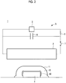
Fig. 2 is a longitudinal sectional view showing a forming device according to an embodiment of the present invention. - Hereinafter, a forming
device 1 according to an embodiment of the present invention will be described with reference toFigs. 1 and2 . - The forming
device 1 according to the embodiment is a device that imparts a formed shape to a plate-shaped material 50 which is, for example, a forming target material made of an aluminum alloy by using a forming die 4. A formedmember 60 formed by the formingdevice 1 is used for aircraft components and the like. - As shown in
Fig. 1 , the formingdevice 1 according to the embodiment includes anelectromagnetic coil 2, apower supply unit 3 that supplies a current to theelectromagnetic coil 2, the formingdie 4, and the like. The formingdevice 1 generates an induced current to a conductive material by theelectromagnetic coil 2 and causes an electromagnetic force to act, similarly to generally known electromagnetic forming. The operating conditions and the like of the formingdevice 1 can be set in the same manner as in usual electromagnetic forming. - The
electromagnetic coil 2 is arranged outside a forming surface of the forming die 4. For example, theelectromagnetic coil 2 is arranged along the surface of the forming die 4 as shown inFig. 1 . Theelectromagnetic coil 2 may have a cylindrical shape for example, and the forming die 4 may be arranged inside theelectromagnetic coil 2. - A large current is supplied from the
power supply unit 3 to theelectromagnetic coil 2. As shown inFig. 1 , apower supply circuit 5 includes a circuit in which acapacitor 6 is installed in parallel with theelectromagnetic coil 2 and a switch 7 is installed between a connection point between thepower supply unit 3 and thecapacitor 6 and theelectromagnetic coil 2. In this configuration, when the switch 7 is open, an electric charge is charged from thepower supply unit 3 to thecapacitor 6 through anelectric resistance 8. Then, by closing the switch 7 and discharging an electric charge charged in thecapacitor 6, a large current to theelectromagnetic coil 2 is generated. - A
fluid 10 is a material having conductivity and fluidity. Thefluid 10 is accommodated in arubber bag 11, for example. Thefluid 10 is, for example, a metal powder or a liquid in which a metal powder is dispersed. The metal powder is, for example, an iron powder. The liquid is oil, for example, and fluidity and rust prevention are ensured. In the liquid in which a metal powder is dispersed, a ratio of the metal powder to the liquid is preferably 50% by mass or more, and if possible, 75% by mass or more. Although there is a possibility that a load pressure at the time of forming is reduced, even in a case where the material has a value smaller than the above described example, it can be applied as thefluid 10 as long as forming can be performed by the material. Further, thefluid 10 may be a low melting point metal. A low melting point metal is, for example, lead or tin. By setting an environment of the formingdevice 1 to an environment with equal to or more than the melting point of thefluid 10 which is a low melting point metal, thefluid 10 can be used in a fluidized and liquefied state. - The
fluid 10 is placed on one surface side of the plate-shaped material 50 which is the forming target material, and the formingdie 4 is installed on the other surface side of the plate-shaped material 50 with the plate-shaped material 50 interposed therebetween. - By causing a large current to instantaneously flow through the
electromagnetic coil 2, an induced current is generated on the surface of thefluid 10 arranged along theelectromagnetic coil 2. As a result, an electromagnetic force acts on thefluid 10, thefluid 10 moves toward the formingdie 4, and thefluid 10 and the plate-shaped material 50 are pressed against the forming die 4. - Before forming, the plate-
shaped material 50 which is the forming target material is placed on the forming surface of the formingdie 4. The forming die 4 is a male die and imparts the formed shape to the plate-shaped material 50. - In the forming method using the forming
device 1 according to the embodiment, first, the plate-shaped material 50 is placed on the forming surface of the formingdie 4 as shown inFig. 1 . Furthermore, the fluid 10 is placed on an upper surface of the plate-shapedmaterial 50 placed on the formingdie 4. - Next, a current is supplied to the
electromagnetic coil 2. As a result, an induced current is generated on the surface of the fluid 10 and an electromagnetic force acts on the fluid 10, so that the fluid 10 moves toward the formingdie 4, and the fluid 10 presses the plate-shapedmaterial 50 against the formingdie 4. At this time, the fluidity of the fluid 10 decreases, and the fluid 10 can strongly press the plate-shapedmaterial 50. Thereby, as shown inFig. 2 , the plate-shapedmaterial 50 is formed along the formingdie 4 to form the formedmember 60. After pressing the plate-shapedmaterial 50 for a predetermined time, the supply of a current is cut off, whereby the action of the electromagnetic force on the fluid 10 can be stopped. Accordingly, fluidity of the fluid 10 is restored. - As described above, according to the forming
device 1 according to the embodiment, by generating the electromagnetic force in the fluid 10, a larger pressing force can be generated in a short time as compared with a related rubber forming press in which the plate-shaped material is pressed against the forming die by only a fluid pressure of the fluid. - Stated another way, the plate-shaped
material 50 is formed at a high speed with a large pressing force by using the electromagnetic force acting on the fluid 10, and thus the plate-shaped material can be formed in a shape along the formingdie 4 with high accuracy and the spring back amount is reduced in the resulting formedmember 60. In particular, in the case of an aluminum alloy, it is a material having a higher breaking elongation as the strain rate becomes higher, and has a great effect of reducing the spring back amount by being formed at a high speed. Therefore, since the insufficiency of the formation amount of the formedmember 60 is unlikely to occur, the strain correction work after forming can also be reduced. In addition, since forming can be accurately performed, the formedmember 60 can be formed without generating unnecessary wrinkles even in a case of forming a flange (a shrinkage flange) having an outwardly projected curved surface. A magnesium alloy (such as AZ80) is known as a material having a higher breaking elongation as the strain rate increases, in addition to an aluminum alloy, and an effect of reducing the spring back amount can be obtained. - In the above embodiment, the case where the formed
member 60 is formed for the first time from the unprocessed plate-shapedmaterial 50 has been described, but the present invention is not limited thereto. For example, the present invention can be applied to a case where the formingdie 4 is pressed against the processed formedmember 60 to correct the shape of the formedmember 60. -
- 1:
- forming device
- 2:
- electromagnetic coil
- 3:
- power supply unit
- 4:
- forming die
- 5:
- power supply circuit
- 6:
- capacitor
- 7:
- switch
- 8:
- electric resistance
- 10:
- fluid
- 11:
- bag
- 50:
- plate-shaped material
- 60:
- formed member
Claims (3)
- A forming device comprising:an electromagnetic coil;a fluid having conductivity and installed on one surface side of a forming target material along the forming target material; anda forming die installed on the other surface side of the forming target material and formed so as to impart a formed shape to the forming target material,wherein an electromagnetic force generated by the electromagnetic coil is caused to act on the fluid so that the fluid presses the forming target material against to the forming die.
- The forming device according to Claim 1,
wherein the fluid is a metal powder, a liquid in which a metal powder is dispersed, or a liquefied metal. - The forming device according to Claim 1 or 2,
wherein the fluid is accommodated in a bag-shaped member.
Applications Claiming Priority (2)
| Application Number | Priority Date | Filing Date | Title |
|---|---|---|---|
| JP2017233421A JP2019098379A (en) | 2017-12-05 | 2017-12-05 | Forming device |
| PCT/JP2018/038397 WO2019111538A1 (en) | 2017-12-05 | 2018-10-16 | Molding device |
Publications (2)
| Publication Number | Publication Date |
|---|---|
| EP3677358A1 true EP3677358A1 (en) | 2020-07-08 |
| EP3677358A4 EP3677358A4 (en) | 2020-11-18 |
Family
ID=66751502
Family Applications (1)
| Application Number | Title | Priority Date | Filing Date |
|---|---|---|---|
| EP18886210.6A Withdrawn EP3677358A4 (en) | 2017-12-05 | 2018-10-16 | Molding device |
Country Status (4)
| Country | Link |
|---|---|
| US (1) | US20200282442A1 (en) |
| EP (1) | EP3677358A4 (en) |
| JP (1) | JP2019098379A (en) |
| WO (1) | WO2019111538A1 (en) |
Families Citing this family (2)
| Publication number | Priority date | Publication date | Assignee | Title |
|---|---|---|---|---|
| CN114472667A (en) * | 2020-11-11 | 2022-05-13 | 湖北汽车工业学院 | An electromagnetic forming device based on flexible medium |
| CN119304069A (en) * | 2024-11-19 | 2025-01-14 | 中航西安飞机工业集团股份有限公司 | A hydraulic forming die and method for sheet metal parts of different-direction S-bend partitions |
Family Cites Families (11)
| Publication number | Priority date | Publication date | Assignee | Title |
|---|---|---|---|---|
| FR1436026A (en) * | 1966-12-02 | 1966-04-22 | Peugeot & Cie Sa | Method and apparatus for stamping |
| US3541824A (en) * | 1969-08-20 | 1970-11-24 | Marvin A Frenkel | Magnetic forming methods and apparatus |
| US3618350A (en) * | 1969-12-15 | 1971-11-09 | Boeing Co | Reusable tooling for electromagnetic forming |
| US3888098A (en) * | 1974-02-27 | 1975-06-10 | Boeing Co | Liquid metal core transpactor elements for electromagnetic forming tools |
| JPS5913933B2 (en) * | 1979-05-24 | 1984-04-02 | ジヤパツクス株式会社 | Molding method using improved core metal |
| FR2570303B1 (en) * | 1984-09-19 | 1993-12-03 | Leroy Maurice | DEVICES FOR FORMING MATERIALS USING INTENSE AND PULSED MAGNETIC FIELDS AND A FLUID |
| JPH0623442A (en) | 1992-07-10 | 1994-02-01 | Showa Alum Corp | Multi-stage electromagnetic plastic working method of hollow material |
| DK0868233T3 (en) * | 1995-12-20 | 2002-08-19 | Pulsar Welding Ltd | Electromagnetic joining or welding of metal objects |
| JP2001246424A (en) * | 2000-02-29 | 2001-09-11 | Japan Aircraft Mfg Co Ltd | Press forming apparatus and press forming method |
| JP2007296553A (en) | 2006-04-28 | 2007-11-15 | Topre Corp | Thin plate electromagnetic forming equipment |
| KR20160077289A (en) * | 2014-12-22 | 2016-07-04 | 주식회사 포스코 | Forming apparatus |
-
2017
- 2017-12-05 JP JP2017233421A patent/JP2019098379A/en active Pending
-
2018
- 2018-10-16 WO PCT/JP2018/038397 patent/WO2019111538A1/en not_active Ceased
- 2018-10-16 US US16/650,990 patent/US20200282442A1/en not_active Abandoned
- 2018-10-16 EP EP18886210.6A patent/EP3677358A4/en not_active Withdrawn
Also Published As
| Publication number | Publication date |
|---|---|
| JP2019098379A (en) | 2019-06-24 |
| US20200282442A1 (en) | 2020-09-10 |
| EP3677358A4 (en) | 2020-11-18 |
| WO2019111538A1 (en) | 2019-06-13 |
Similar Documents
| Publication | Publication Date | Title |
|---|---|---|
| CN202367044U (en) | V-shaped member bending die with inclined wedges | |
| US20200282442A1 (en) | Molding device | |
| CN103624132B (en) | Apparatus and method for electrohydraulic forming | |
| EP3320997A1 (en) | Protrusion molding device, protrusion molding method, and molded article | |
| CN104096744A (en) | Low-noise punching die | |
| CN104690556A (en) | Fully automatic bearing forging manipulator production line | |
| US8250897B2 (en) | High strength workpiece material and method and apparatus for producing the same | |
| Reddy | Impact of high temperature and beta-phase on formability of cylindrical cups from Cu-28% Zn and cu-37% Zn alloys | |
| US9802252B2 (en) | Method for controlling powder compacting apparatus and compacting apparatus | |
| Zhao et al. | Electromagnetic micro-punching process of T2 copper foil | |
| KR101747585B1 (en) | Method for molding cylindrical container with boss | |
| CN104439014A (en) | Full automatic fastener forging and pressing manipulator production line | |
| JP5600187B2 (en) | Work punching method and work punch forming apparatus | |
| US20140338415A1 (en) | Method for operation of an indirect extrusion press and an indirect extrusion press | |
| US11253901B2 (en) | Indirect electrohydraulic press forming tool, device and method | |
| CN105344972A (en) | Rapid forming method for amorphous alloy parts | |
| RU2692005C1 (en) | Device for magnetic-pulse punching | |
| RU144975U1 (en) | STAMP FOR ANGULAR PRESS | |
| RU2693409C1 (en) | Device for magnetic-pulse punching | |
| RU2691014C1 (en) | Device for magnetic-pulse punching | |
| CN104475473A (en) | Equal channel angular extrusion mold with characteristic of electric material discharge | |
| Mamutov et al. | Electrohydraulic forming of light weight automotive panels | |
| RU2097162C1 (en) | Apparatus for expanding tubular blanks | |
| JP7063074B2 (en) | Press processing equipment | |
| JP2014196551A (en) | Cold plastic working apparatus |
Legal Events
| Date | Code | Title | Description |
|---|---|---|---|
| PUAI | Public reference made under article 153(3) epc to a published international application that has entered the european phase |
Free format text: ORIGINAL CODE: 0009012 |
|
| STAA | Information on the status of an ep patent application or granted ep patent |
Free format text: STATUS: REQUEST FOR EXAMINATION WAS MADE |
|
| 17P | Request for examination filed |
Effective date: 20200331 |
|
| AK | Designated contracting states |
Kind code of ref document: A1 Designated state(s): AL AT BE BG CH CY CZ DE DK EE ES FI FR GB GR HR HU IE IS IT LI LT LU LV MC MK MT NL NO PL PT RO RS SE SI SK SM TR |
|
| AX | Request for extension of the european patent |
Extension state: BA ME |
|
| A4 | Supplementary search report drawn up and despatched |
Effective date: 20201019 |
|
| RIC1 | Information provided on ipc code assigned before grant |
Ipc: B21D 22/12 20060101ALI20201013BHEP Ipc: B21D 26/14 20060101AFI20201013BHEP |
|
| DAV | Request for validation of the european patent (deleted) | ||
| DAX | Request for extension of the european patent (deleted) | ||
| 18W | Application withdrawn |
Effective date: 20210331 |