EP3677357A1 - Sheet material press forming method - Google Patents
Sheet material press forming method Download PDFInfo
- Publication number
- EP3677357A1 EP3677357A1 EP18879610.6A EP18879610A EP3677357A1 EP 3677357 A1 EP3677357 A1 EP 3677357A1 EP 18879610 A EP18879610 A EP 18879610A EP 3677357 A1 EP3677357 A1 EP 3677357A1
- Authority
- EP
- European Patent Office
- Prior art keywords
- shape
- press forming
- dimensional elements
- discretized
- forming
- Prior art date
- Legal status (The legal status is an assumption and is not a legal conclusion. Google has not performed a legal analysis and makes no representation as to the accuracy of the status listed.)
- Granted
Links
- 238000000034 method Methods 0.000 title claims abstract description 40
- 239000000463 material Substances 0.000 title claims abstract description 8
- 230000005489 elastic deformation Effects 0.000 claims abstract description 5
- 239000002184 metal Substances 0.000 claims description 10
- 230000037303 wrinkles Effects 0.000 abstract description 12
- 229910000831 Steel Inorganic materials 0.000 abstract description 9
- 239000010959 steel Substances 0.000 abstract description 9
- 206010017076 Fracture Diseases 0.000 description 25
- 238000012733 comparative method Methods 0.000 description 14
- 238000007796 conventional method Methods 0.000 description 10
- 208000010392 Bone Fractures Diseases 0.000 description 9
- 238000005452 bending Methods 0.000 description 4
- 238000013461 design Methods 0.000 description 4
- 230000008602 contraction Effects 0.000 description 2
- 238000010586 diagram Methods 0.000 description 2
- 239000013585 weight reducing agent Substances 0.000 description 2
- 230000037396 body weight Effects 0.000 description 1
- 238000011161 development Methods 0.000 description 1
- 230000000694 effects Effects 0.000 description 1
- 230000007613 environmental effect Effects 0.000 description 1
- 238000004519 manufacturing process Methods 0.000 description 1
- 238000005728 strengthening Methods 0.000 description 1
Images


Classifications
-
- B—PERFORMING OPERATIONS; TRANSPORTING
- B21—MECHANICAL METAL-WORKING WITHOUT ESSENTIALLY REMOVING MATERIAL; PUNCHING METAL
- B21D—WORKING OR PROCESSING OF SHEET METAL OR METAL TUBES, RODS OR PROFILES WITHOUT ESSENTIALLY REMOVING MATERIAL; PUNCHING METAL
- B21D22/00—Shaping without cutting, by stamping, spinning, or deep-drawing
- B21D22/20—Deep-drawing
-
- B—PERFORMING OPERATIONS; TRANSPORTING
- B21—MECHANICAL METAL-WORKING WITHOUT ESSENTIALLY REMOVING MATERIAL; PUNCHING METAL
- B21D—WORKING OR PROCESSING OF SHEET METAL OR METAL TUBES, RODS OR PROFILES WITHOUT ESSENTIALLY REMOVING MATERIAL; PUNCHING METAL
- B21D22/00—Shaping without cutting, by stamping, spinning, or deep-drawing
- B21D22/02—Stamping using rigid devices or tools
-
- B—PERFORMING OPERATIONS; TRANSPORTING
- B21—MECHANICAL METAL-WORKING WITHOUT ESSENTIALLY REMOVING MATERIAL; PUNCHING METAL
- B21D—WORKING OR PROCESSING OF SHEET METAL OR METAL TUBES, RODS OR PROFILES WITHOUT ESSENTIALLY REMOVING MATERIAL; PUNCHING METAL
- B21D22/00—Shaping without cutting, by stamping, spinning, or deep-drawing
- B21D22/20—Deep-drawing
- B21D22/26—Deep-drawing for making peculiarly, e.g. irregularly, shaped articles
-
- G—PHYSICS
- G06—COMPUTING; CALCULATING OR COUNTING
- G06F—ELECTRIC DIGITAL DATA PROCESSING
- G06F30/00—Computer-aided design [CAD]
-
- G—PHYSICS
- G06—COMPUTING; CALCULATING OR COUNTING
- G06F—ELECTRIC DIGITAL DATA PROCESSING
- G06F30/00—Computer-aided design [CAD]
- G06F30/10—Geometric CAD
- G06F30/17—Mechanical parametric or variational design
-
- G—PHYSICS
- G06—COMPUTING; CALCULATING OR COUNTING
- G06F—ELECTRIC DIGITAL DATA PROCESSING
- G06F30/00—Computer-aided design [CAD]
- G06F30/20—Design optimisation, verification or simulation
- G06F30/23—Design optimisation, verification or simulation using finite element methods [FEM] or finite difference methods [FDM]
-
- B—PERFORMING OPERATIONS; TRANSPORTING
- B21—MECHANICAL METAL-WORKING WITHOUT ESSENTIALLY REMOVING MATERIAL; PUNCHING METAL
- B21D—WORKING OR PROCESSING OF SHEET METAL OR METAL TUBES, RODS OR PROFILES WITHOUT ESSENTIALLY REMOVING MATERIAL; PUNCHING METAL
- B21D53/00—Making other particular articles
- B21D53/88—Making other particular articles other parts for vehicles, e.g. cowlings, mudguards
-
- G—PHYSICS
- G06—COMPUTING; CALCULATING OR COUNTING
- G06F—ELECTRIC DIGITAL DATA PROCESSING
- G06F2113/00—Details relating to the application field
- G06F2113/24—Sheet material
Definitions
- This disclosure relates to a sheet material press forming method which makes it possible to stably obtain a target shape while preventing fracture of a metal blank when parts such as automotive parts are manufactured from the metal blank by press forming.
- automotive parts are often manufactured using press forming excellent in terms of manufacturing costs.
- strengthening of steel sheets to be used for automotive body weight reduction means thinning of steel sheets, and as the sheet thickness of a steel sheet is made thinner, press wrinkles tend to be caused.
- WO 2017/006793 A (PTL 1) and JP 5867657 B (PTL 2) describe a method in which a preformed shape having no fractures or press wrinkles is manufactured and subsequently subjected to press forming to thereby obtain a product having no fractures or press wrinkles.
- PTL 1 and PTL 2 each propose a method of preparing a preformed shape for suppressing fractures and subsequently subjecting the preformed shape to restrike forming.
- PTL 1 uses the large scale of inflow and rotation of materials in a subsequent process, the method of PTL 1 can be applied only to a fracture risk portion of a flange portion, which has an open periphery and at which a metallic sheet is allowed to move easily.
- PTL 2 indicates the design guideline of a preformed shape in order to suppress forming failure inside a product
- PTL 2 merely discusses changing of shapes in cross sections taken by dividing a final shape in a grid pattern or taken radially from the centroid.
- a metallic sheet is not necessarily deformed in grid-like directions or radially from the centroid during actual restrike forming but deformed three-dimensionally in arbitrary directions.
- the method of PTL 2 is markedly labor intensive and time consuming.
- a formed part having a hat-like cross-sectional shape and including a top portion, a side wall portion, and a flange portion is formed from a metal blank, it is possible to automatically design an optimal preformed shape by finite element analysis, and as a result, press forming can be performed from a metal blank without causing fractures or press wrinkles.
- the top portion 11 having a protrusion 14 having a protrusive shape with a closed periphery, that is, a blockage protrusive shape is formed in a single step using a tool of press forming, when a target shape is complicated and a used metallic sheet has low ductility, a fracture occurs near the protrusion and a product having a target shape cannot be obtained.
- a method of dividing the press forming process into a plurality of steps is sometimes used. That is, press forming is performed to form a rough shape in a preforming step and press forming is performed again (restrike) in the subsequent step to obtain a target shape. At that time, a shape formed in the preforming step (hereinafter, referred to as "preformed shape”) has been conventionally designed depending on design expert's experience and know-how.
- the metallic sheet during restrike is rarely deformed in the cross sections in a grid-like form or taken radially from the centroid.
- the metallic sheet moves three dimensionally in arbitrarily directions almost across the entire region. Therefore, only with the idea of matching the cross-sectional line lengths described in PTL 2, failures such as fractures and wrinkles often occur during the restrike, and trials and errors need to be repeated to determine the shape of the preformed shape. In the worst case, an optimal shape of the preformed shape may not be determined.
- the inventors conceived of determining an optimal preformed shape by using a three-dimensional finite element method as press forming analysis.
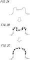
- FIG. 2A illustrates one example of the target shape of the protrusion.
- FIGS. 2A to 2C illustrate a two-dimensional cross section to illustrate clearly, it is necessary to consider a three-dimensional shape in practice.
- protrusion regions 1 to 8 to form the target shape are discretized into two-dimensional elements and nodes (making a mesh) as illustrated in FIG. 2B . It is preferable to make the distance between adjacent ones of the nodes indicated by Nos. 1 to 8 as equal as possible.
- a rough preformed shape which makes forming of a final shape easy in the subsequent step is determined ( FIG. 2C ).
- the sides connected by the nodes bend freely and that the determined rough preformed shape has approximately the same surface area as the target shape.
- the discretized portion is applied to the discretized portion from the inside in normal directions of the two-dimensional elements (also referred to as "shell elements") to determine the preformed shape.
- Important points are (a) the two-dimensional elements should be deformed within an elastic deformation range and (b) an angle between adjacent ones of the the two-dimensional elements should be free to change.
- the rough preformed shape is determined as illustrated in FIG. 2C .
- a tool of press forming having the preformed shape determined as described above ( FIG. 2C ) is made, and a blank is formed into the preformed shape and subsequently formed into the target shape ( FIG. 2A ) by restrike.
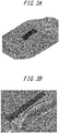
- connection ridge portion between the top portion 11 and the side wall portion 12, including a portion where fractures or wrinkles may occur in the target shape illustrated in FIG. 1 is discretized into two-dimensional elements and nodes, adjacent nodes are connected by a line segment, and a region surrounded by the line segments is determined as a two-dimensional element (making a mesh).
- FIG. 3A This schematic diagram is illustrated in FIG. 3A.
- FIG. 3B is an enlarged view of an essential part.
- the distance between discretized nodes is not particularly limited, but it is preferably set to about 50 % to 300 % of the sheet thickness.
- finite element analysis in which the two-dimensional elements constituting the discretized portion are applied with internal pressure from the inside of the discretized portion in normal directions of the two-dimensional elements for deformation is performed. At that time, the analysis is performed under conditions that the two-dimensional elements are deformed within the elastic deformation range and an angle between adjacent two-dimensional elements are free to change.
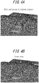
- FIG. 4A illustrates the shape of the preformed shape after the application of internal pressure
- FIG. 4B illustrates the target shape.
- the preformed shape thus obtained has a rougher shape than the target shape and can avoid local deformation and stress concentration, and thus, it is free from fractures or wrinkles. Further, when the preformed shape is crash formed into the target shape, bending deformation is only applied to the two-dimensional elements and nodes in the crash forming, and thus the two-dimensional elements are less easily deformed. Accordingly, the preformed shape can be obtained without fractures or wrinkles, and when the preformed shape is press formed into the target shape, additional elongation or contraction will not occur. Thus, the target shape can be eventually obtained without fractures or wrinkles.
- a part having a shape illustrated in FIG. 1 was manufactured by press forming.
- the metallic sheet of the part was a steel sheet having a tensile strength of 1180 MPa and a sheet thickness of 1.2 mm.
- a method having only one step of draw forming was used as a conventional method (conventional method 1).
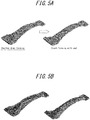
- FIG. 5A illustrates a formed shape and FIG. 5B illustrates a position at which the pad is held.
- the disclosed method had a first step of draw forming and a second step of crash forming (disclosed method 1).
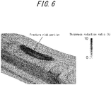
- FIG. 6 a forming result of the conventional method 1 is illustrated in FIG. 6 .
- a large local thickness reduction occurred, which might lead to fraction.
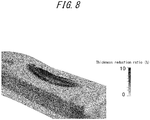
- FIG. 7 a result of shallow draw forming of the preformed shape is illustrated in FIG. 7 and a result of subjecting the preformed shape to crash forming with pad to obtain a target shape is illustrated in FIG. 8 .
- FIG. 8 a result of subjecting the preformed shape to crash forming with pad to obtain a target shape is illustrated in FIG. 8 .
- the preformed shape was subjected to press forming analysis by the finite element method.
- FIGS. 3A and 3B a part of the side wall portion and the top portion were discretized into two-dimensional elements and nodes. In the discretization, the interval between adjacent nodes was set to about 1.2 mm which was roughly equivalent to the sheet thickness.
- the two-dimensional elements were applied with internal pressure in the normal directions using finite element analysis.
- FIG. 4A The shape illustrated in FIG. 4A was regarded as the shape of the preformed shape.
- a tool of press forming was prepared and the preformed shape was draw formed using the tool.
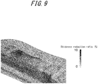
- FIG. 9 Comparing FIG. 9 with not only FIG. 6 but also FIGS. 7 and 8 , it can be seen that the thickness reduction was mitigated to prevent fractures.
- FIG. 10 a result of crash forming, as the second step, using a tool of press forming having the target shape is illustrated in FIG. 10 . Since no significant thickness reduction occurred in the second step and no fracture occurred, it was confirmed that the method according to this disclosure is effective.
- a part having a shape illustrated in FIG. 11 was manufactured by press forming.
- the metallic sheet of the part was a steel sheet having a tensile strength of 1180 MPa and a sheet thickness of 1.2 mm.
- Example 2 a method having only one step of draw forming was used as a conventional method (conventional method 2).
- a method having a first step of shallow draw forming and a second step of crash forming with pad was used as a comparative method (comparative method 2).
- the disclosed method had a first step of draw forming and a second step of crash forming (disclosed method 2).
- FIG. 12 a forming result of the conventional method 2 is illustrated in FIG. 12 .
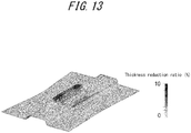
- FIG. 13 a result of shallow draw forming is illustrated in FIG. 13 and a result of the crash forming with pad of the comparative method 2 is illustrated in FIG. 14 .
- FIG. 14 a result of the crash forming with pad of the comparative method 2 is illustrated in FIG. 14 .
- the preformed shape was subjected to press forming analysis by the finite element method.
- FIGS. 15A and 15B a part of the side wall portion and the top portion were discretized into two-dimensional elements and nodes. In the discretization, the interval between adjacent nodes was set to about 1.2 mm which was roughly equivalent to the sheet thickness.
- the two-dimensional elements were applied with internal pressure in the normal directions using finite element analysis.
- FIG. 16A FIG. 16B illustrates the target shape.
- the shape illustrated in FIG. 16A was regarded as the shape of the preformed shape and draw formed using a tool of press forming.
- FIG. 17 Comparing FIG. 17 with not only FIG. 12 but also FIGS. 13 and 14 , it can be seen that the thickness reduction was mitigated to prevent fractures.
- FIG. 18 a result of crash forming using a tool of draw forming having the target shape as the second step is illustrated in FIG. 18 . Since no significant thickness reduction occurred in the second step and no fracture occurred, it was confirmed that the method according to this disclosure is effective.
Abstract
Description
- This disclosure relates to a sheet material press forming method which makes it possible to stably obtain a target shape while preventing fracture of a metal blank when parts such as automotive parts are manufactured from the metal blank by press forming.
- Recently, in view of global environmental issues, high-strength steel sheets have been used frequently as automotive parts for weight reduction of an automotive body.
- Further, automotive parts are often manufactured using press forming excellent in terms of manufacturing costs.
- However, since high-strength steel sheets have low ductility and easily suffer fractures, compared to low-strength steel sheets, it is not always easy to obtain parts having a target shape by press forming.
- Further, strengthening of steel sheets to be used for automotive body weight reduction means thinning of steel sheets, and as the sheet thickness of a steel sheet is made thinner, press wrinkles tend to be caused.
- Therefore, the development of a press forming method is strongly required to suppress fractures and press wrinkles.
-
WO 2017/006793 A (PTL 1) andJP 5867657 B -
- PTL 1:
WO 2017/006793 A - PTL 2:
JP 5867657 B - As a method for suppressing fractures during press forming, it is considered useful to prepare a rough preformed shape as a preforming step and subsequently subject the preformed shape to restrike forming to obtain a target shape.
-
PTL 1 andPTL 2 each propose a method of preparing a preformed shape for suppressing fractures and subsequently subjecting the preformed shape to restrike forming. - However, since
PTL 1 uses the large scale of inflow and rotation of materials in a subsequent process, the method ofPTL 1 can be applied only to a fracture risk portion of a flange portion, which has an open periphery and at which a metallic sheet is allowed to move easily. - Further, although
PTL 2 indicates the design guideline of a preformed shape in order to suppress forming failure inside a product,PTL 2 merely discusses changing of shapes in cross sections taken by dividing a final shape in a grid pattern or taken radially from the centroid. A metallic sheet is not necessarily deformed in grid-like directions or radially from the centroid during actual restrike forming but deformed three-dimensionally in arbitrary directions. Thus, when a preformed shape is designed without considering this point, it is impossible to control the inflow of the metallic sheet. Further, the method ofPTL 2 is markedly labor intensive and time consuming. - This disclosure could thus be helpful to provide a sheet material press forming method in which, considering three-dimensional deformation, press forming is divided into two steps, in which a sheet material is preformed into a shape having the same surface area as a target shape and easy to form in the first step and subsequently formed into the target shape without fractures.
- That is, the primary features of this disclosure are as follows.
- 1. A sheet material press forming method of press forming a formed part having a hat-like cross-sectional shape and including a top portion, a side wall portion, and a flange portion, the top portion having a protrusion with a blockage protrusive shape, from a metal blank, the method comprising:
- first, for the top portion in a region of the protrusion, determining, by press forming analysis, a preforming shape which has almost the same surface area as a target shape and is easy to form according to the following steps S1 and S2;
- then, press forming the metal blank into the preforming shape, and subsequently crash forming a pertinent portion of the metal blank into a target final shape,
where- S1: the region of the protrusion having the target shape is discretized into two-dimensional elements and nodes for finite element analysis, and
- S2: a discretized portion is applied with internal stress in normal directions of the two-dimensional elements from the inside of the discretized portion and deformed under the following conditions:
- (a) the two-dimensional elements are deformed within an elastic deformation range; and
- (b) adjacent ones of the two-dimensional elements have an angle therebetween which is free to change.
- According to this disclosure, when a formed part having a hat-like cross-sectional shape and including a top portion, a side wall portion, and a flange portion, the top portion having a protrusion having a protrusive shape with a closed periphery, is formed from a metal blank, it is possible to automatically design an optimal preformed shape by finite element analysis, and as a result, press forming can be performed from a metal blank without causing fractures or press wrinkles.
- In the accompanying drawings:
-
FIG. 1 illustrates a formed part including a top portion having a protrusion with a blockage protrusive shape; -
FIG. 2A is a schematic diagram indicating the concept of this disclosure and illustrates one example of target shapes of the protrusion; -
FIG. 2B illustrates a state in which the protrusion is discretized into two-dimensional elements and nodes; -
FIG. 2C illustrates a preformed shape of the protrusion; -
FIG. 3A illustrates a state in which a surrounding portion of the projection is discretized; -
FIG. 3B is an enlarged view of an essential part ofFIG. 3A ; -
FIG. 4A illustrates the shape of a preformed shape after the discretized portion is applied with internal pressure; -
FIG. 4B illustrates a target shape of the discretized portion; -
FIG. 5A illustrates a comparative method including a first step of shallow draw forming and a second step of bending deformation with pad; -
FIG. 5B illustrates a position at which the pad is held inFIG. 5A ; -
FIG. 6 illustrates a thickness reduction ratio when aconventional method 1 is used for forming; -
FIG. 7 illustrates a thickness reduction ratio during shallow draw forming (first step) in acomparative method 1; -
FIG. 8 illustrates a thickness reduction ratio during bending deformation with pad (second step) in thecomparative method 1; -
FIG. 9 illustrates a thickness reduction ratio when a preformed shape is formed according to a disclosedmethod 1; -
FIG. 10 illustrates a thickness reduction ratio when a target shape is formed according to the disclosedmethod 1; -
FIG. 11 illustrates the shape of a part to be used in Example 2; -
FIG. 12 illustrates a thickness reduction ratio when the part to be used in Example 2 is formed according to aconventional method 2; -
FIG. 13 illustrates a thickness reduction ratio of the part to be formed in Example 2 during shallow draw forming (first step) in acomparative method 2; -
FIG. 14 illustrates a thickness reduction ratio of the part to be formed in Example 2 during bending deformation with pad (second step) in thecomparative method 2; -
FIG. 15A illustrates a state in which a surrounding portion of a fracture risk portion of the part used in Example 2 is discretized; -
FIG. 15B is an enlarged view of an essential part ofFIG. 15A ; -
FIG. 16A illustrates the shape of the preformed shape after the discretized portion is applied with internal pressure; -
FIG. 16B illustrates a target shape of the discretized portion; -
FIG. 17 illustrates a thickness reduction ratio when a preformed shape is formed according to a disclosedmethod 2; and -
FIG. 18 illustrates a thickness reduction ratio when a target shape is formed according to the disclosedmethod 2. - The following describes the present disclosure in detail.
- For example, as illustrated in
FIG. 1 , even if a formedpart 10 having a hat-like cross-sectional shape and including atop portion 11, aside wall portion 12, and aflange portion 13, thetop portion 11 having aprotrusion 14 having a protrusive shape with a closed periphery, that is, a blockage protrusive shape is formed in a single step using a tool of press forming, when a target shape is complicated and a used metallic sheet has low ductility, a fracture occurs near the protrusion and a product having a target shape cannot be obtained. - In order to solve this problem, a method of dividing the press forming process into a plurality of steps is sometimes used. That is, press forming is performed to form a rough shape in a preforming step and press forming is performed again (restrike) in the subsequent step to obtain a target shape. At that time, a shape formed in the preforming step (hereinafter, referred to as "preformed shape") has been conventionally designed depending on design expert's experience and know-how.
- Recently, a design has been made based on the idea of taking, in a preformed shape, product cross sections including fracture regions in a grid pattern or radially from the centroid, deforming the preformed shape, keeping the cross-sectional line lengths of the cross sections in a suitable range to thereby suppress the elongation and contraction of a metallic sheet in the restrike step, which makes it possible to obtain a product without fractures or wrinkles (for example, PTL 2).
- However, the metallic sheet during restrike is rarely deformed in the cross sections in a grid-like form or taken radially from the centroid. Typically, the metallic sheet moves three dimensionally in arbitrarily directions almost across the entire region. Therefore, only with the idea of matching the cross-sectional line lengths described in
PTL 2, failures such as fractures and wrinkles often occur during the restrike, and trials and errors need to be repeated to determine the shape of the preformed shape. In the worst case, an optimal shape of the preformed shape may not be determined. - Therefore, to deal with three-dimensional deformation of the metallic sheet which cannot be dealt with relying on the idea of using the cross-sectional line length, the inventors conceived of determining an optimal preformed shape by using a three-dimensional finite element method as press forming analysis.
- The following describes the concept of this disclosure based on
FIGS. 2A to 2C . -
FIG. 2A illustrates one example of the target shape of the protrusion. AlthoughFIGS. 2A to 2C illustrate a two-dimensional cross section to illustrate clearly, it is necessary to consider a three-dimensional shape in practice. - Then,
protrusion regions 1 to 8 to form the target shape are discretized into two-dimensional elements and nodes (making a mesh) as illustrated inFIG. 2B . It is preferable to make the distance between adjacent ones of the nodes indicated by Nos. 1 to 8 as equal as possible. - Then, using the finite element method, a rough preformed shape which makes forming of a final shape easy in the subsequent step is determined (
FIG. 2C ). At that time, it is preferable that the sides connected by the nodes bend freely and that the determined rough preformed shape has approximately the same surface area as the target shape. - Specifically, internal stress is applied to the discretized portion from the inside in normal directions of the two-dimensional elements (also referred to as "shell elements") to determine the preformed shape. Important points are (a) the two-dimensional elements should be deformed within an elastic deformation range and (b) an angle between adjacent ones of the the two-dimensional elements should be free to change.
- Thus, the rough preformed shape is determined as illustrated in
FIG. 2C . - Next, in actual press forming, a tool of press forming having the preformed shape determined as described above (
FIG. 2C ) is made, and a blank is formed into the preformed shape and subsequently formed into the target shape (FIG. 2A ) by restrike. - Next, specific procedures using the above method will be described.
- First, a connection ridge portion between the
top portion 11 and theside wall portion 12, including a portion where fractures or wrinkles may occur in the target shape illustrated inFIG. 1 , is discretized into two-dimensional elements and nodes, adjacent nodes are connected by a line segment, and a region surrounded by the line segments is determined as a two-dimensional element (making a mesh). This schematic diagram is illustrated inFIG. 3A. FIG. 3B is an enlarged view of an essential part. At that time, the distance between discretized nodes is not particularly limited, but it is preferably set to about 50 % to 300 % of the sheet thickness. - Next, finite element analysis in which the two-dimensional elements constituting the discretized portion are applied with internal pressure from the inside of the discretized portion in normal directions of the two-dimensional elements for deformation is performed. At that time, the analysis is performed under conditions that the two-dimensional elements are deformed within the elastic deformation range and an angle between adjacent two-dimensional elements are free to change.
- Thus, the shape of the preformed shape which is easy to form since the shape is rougher than the target shape and has the same surface area as the target shape can be readily obtained. One example of the shape of the preformed shape thus obtained is illustrated in
FIG. 4A. FIG. 4A illustrates the shape of the preformed shape after the application of internal pressure andFIG. 4B illustrates the target shape. - The preformed shape thus obtained has a rougher shape than the target shape and can avoid local deformation and stress concentration, and thus, it is free from fractures or wrinkles. Further, when the preformed shape is crash formed into the target shape, bending deformation is only applied to the two-dimensional elements and nodes in the crash forming, and thus the two-dimensional elements are less easily deformed. Accordingly, the preformed shape can be obtained without fractures or wrinkles, and when the preformed shape is press formed into the target shape, additional elongation or contraction will not occur. Thus, the target shape can be eventually obtained without fractures or wrinkles.
- A part having a shape illustrated in
FIG. 1 was manufactured by press forming. The metallic sheet of the part was a steel sheet having a tensile strength of 1180 MPa and a sheet thickness of 1.2 mm. - A method having only one step of draw forming was used as a conventional method (conventional method 1).
- A method having a first step of shallow draw forming and a second step of crash forming with pad as illustrated in
FIG. 5A was used as a comparative method (comparative method 1).FIG. 5A illustrates a formed shape andFIG. 5B illustrates a position at which the pad is held. - The disclosed method had a first step of draw forming and a second step of crash forming (disclosed method 1).
- First, a forming result of the
conventional method 1 is illustrated inFIG. 6 . As illustrated inFIG. 6 , using theconventional method 1, a large local thickness reduction occurred, which might lead to fraction. - Further, using the
comparative method 1, a result of shallow draw forming of the preformed shape is illustrated inFIG. 7 and a result of subjecting the preformed shape to crash forming with pad to obtain a target shape is illustrated inFIG. 8 . When thecomparative method 1 was used, local thickness reduction occurred during the draw forming as the first step and the crash forming with pad as the second step and there was a concern that a fracture might occur from this portion. - Next, in performing the disclosed
method 1, the preformed shape was subjected to press forming analysis by the finite element method. As illustrated inFIGS. 3A and 3B , a part of the side wall portion and the top portion were discretized into two-dimensional elements and nodes. In the discretization, the interval between adjacent nodes was set to about 1.2 mm which was roughly equivalent to the sheet thickness. Then, the two-dimensional elements were applied with internal pressure in the normal directions using finite element analysis. The result is illustrated inFIG. 4A . The shape illustrated inFIG. 4A was regarded as the shape of the preformed shape. A tool of press forming was prepared and the preformed shape was draw formed using the tool. The result is illustrated inFIG. 9 . ComparingFIG. 9 with not onlyFIG. 6 but alsoFIGS. 7 and8 , it can be seen that the thickness reduction was mitigated to prevent fractures. - Furthermore, a result of crash forming, as the second step, using a tool of press forming having the target shape is illustrated in
FIG. 10 . Since no significant thickness reduction occurred in the second step and no fracture occurred, it was confirmed that the method according to this disclosure is effective. - A part having a shape illustrated in
FIG. 11 was manufactured by press forming. The metallic sheet of the part was a steel sheet having a tensile strength of 1180 MPa and a sheet thickness of 1.2 mm. - As in Example 1, a method having only one step of draw forming was used as a conventional method (conventional method 2).
- A method having a first step of shallow draw forming and a second step of crash forming with pad was used as a comparative method (comparative method 2).
- The disclosed method had a first step of draw forming and a second step of crash forming (disclosed method 2).
- First, a forming result of the
conventional method 2 is illustrated inFIG. 12 . - As illustrated in
FIG. 12 , using theconventional method 2, a large local thickness reduction occurred, which might lead to fraction. - Further, using the
comparative method 2, a result of shallow draw forming is illustrated inFIG. 13 and a result of the crash forming with pad of thecomparative method 2 is illustrated inFIG. 14 . When thecomparative method 2 was used, local thickness reduction occurred during the draw forming as the first step and the crash forming with pad as the second step and there was also a concern that a fracture might occur from this portion. - Next, in performing the disclosed
method 2, the preformed shape was subjected to press forming analysis by the finite element method. As illustrated inFIGS. 15A and 15B , a part of the side wall portion and the top portion were discretized into two-dimensional elements and nodes. In the discretization, the interval between adjacent nodes was set to about 1.2 mm which was roughly equivalent to the sheet thickness. Then, the two-dimensional elements were applied with internal pressure in the normal directions using finite element analysis. The result is illustrated inFIG. 16A (FIG. 16B illustrates the target shape). The shape illustrated inFIG. 16A was regarded as the shape of the preformed shape and draw formed using a tool of press forming. The result is illustrated inFIG. 17 . ComparingFIG. 17 with not onlyFIG. 12 but alsoFIGS. 13 and14 , it can be seen that the thickness reduction was mitigated to prevent fractures. - Furthermore, a result of crash forming using a tool of draw forming having the target shape as the second step is illustrated in
FIG. 18 . Since no significant thickness reduction occurred in the second step and no fracture occurred, it was confirmed that the method according to this disclosure is effective. -
- 1 to 8
- Nodes of a protrusion region
- 10
- Formed part
- 11
- Top portion
- 12
- Side wall portion
- 13
- Flange portion
- 14
- Protrusion
Claims (1)
- A sheet material press forming method of press forming a formed part having a hat-like cross-sectional shape and including a top portion, a side wall portion, and a flange portion, the top portion having a protrusion with a blockage protrusive shape, from a metal blank, the method comprising:first, for the top portion in a region of the protrusion, determining, by press forming analysis, a preforming shape which has almost the same surface area as a target shape and is easy to form according to the following steps S1 and S2; andthen, press forming the metal blank into the preforming shape, and subsequently crash forming a pertinent portion of the metal blank into a target final shape,
whereS1: the region of the protrusion having the target shape is discretized into two-dimensional elements and nodes for finite element analysis, andS2: a discretized portion is applied with internal stress in the normal directions of the two-dimensional elements from the inside of the discretized portion and deformed under the following conditions:(a) the two-dimensional elements are deformed within an elastic deformation range; and(b) adjacent ones of the two-dimensional elements have an angle therebetween which is free to change.
Applications Claiming Priority (2)
| Application Number | Priority Date | Filing Date | Title |
|---|---|---|---|
| JP2017220224 | 2017-11-15 | ||
| PCT/JP2018/033855 WO2019097829A1 (en) | 2017-11-15 | 2018-09-12 | Sheet material press forming method |
Publications (3)
| Publication Number | Publication Date |
|---|---|
| EP3677357A1 true EP3677357A1 (en) | 2020-07-08 |
| EP3677357A4 EP3677357A4 (en) | 2020-11-11 |
| EP3677357B1 EP3677357B1 (en) | 2024-01-10 |
Family
ID=66539646
Family Applications (1)
| Application Number | Title | Priority Date | Filing Date |
|---|---|---|---|
| EP18879610.6A Active EP3677357B1 (en) | 2017-11-15 | 2018-09-12 | Sheet material press forming method |
Country Status (7)
| Country | Link |
|---|---|
| US (1) | US11376645B2 (en) |
| EP (1) | EP3677357B1 (en) |
| JP (1) | JP6569837B1 (en) |
| KR (1) | KR102333846B1 (en) |
| CN (1) | CN111344078B (en) |
| MX (1) | MX2020005048A (en) |
| WO (1) | WO2019097829A1 (en) |
Family Cites Families (11)
| Publication number | Priority date | Publication date | Assignee | Title |
|---|---|---|---|---|
| JP3206505B2 (en) * | 1997-08-06 | 2001-09-10 | 住友金属工業株式会社 | Hydraulic bulge processing method and hydraulic bulge processing apparatus for metal tube |
| JP4583145B2 (en) * | 2004-11-11 | 2010-11-17 | 株式会社日本総合研究所 | Plate material forming simulation system and plate material forming simulation program |
| JP4596908B2 (en) | 2004-12-28 | 2010-12-15 | 株式会社日本総合研究所 | Multistage molding simulation system and multistage molding simulation program |
| JP4783684B2 (en) * | 2006-06-29 | 2011-09-28 | 株式会社日本総合研究所 | A drawn product model creation system, a drawn product model analysis system provided with the same, a drawn product model creation program, and a drawn product analysis program provided therewith. |
| US20090272171A1 (en) * | 2008-05-05 | 2009-11-05 | Ford Global Technologies, Llc | Method of designing and forming a sheet metal part |
| JP5281519B2 (en) * | 2009-08-26 | 2013-09-04 | トヨタ自動車株式会社 | Press forming method |
| JP2012074000A (en) * | 2010-09-03 | 2012-04-12 | Aisin Aw Co Ltd | Analysis method using finite element method, and analysis arithmetic program using finite element method |
| WO2015004908A1 (en) | 2013-07-09 | 2015-01-15 | Jfeスチール株式会社 | Plate molding method and preliminary molded shape setting method |
| US9921572B2 (en) * | 2013-11-12 | 2018-03-20 | Embraer S.A. | Springback compensation in formed sheet metal parts |
| JP5979164B2 (en) * | 2014-01-27 | 2016-08-24 | Jfeスチール株式会社 | Press forming method |
| MX2018000109A (en) * | 2015-07-06 | 2018-03-22 | Nippon Steel & Sumitomo Metal Corp | Method and apparatus for manufacturing press component. |
-
2018
- 2018-09-12 MX MX2020005048A patent/MX2020005048A/en unknown
- 2018-09-12 JP JP2019505084A patent/JP6569837B1/en active Active
- 2018-09-12 KR KR1020207013738A patent/KR102333846B1/en active IP Right Grant
- 2018-09-12 WO PCT/JP2018/033855 patent/WO2019097829A1/en unknown
- 2018-09-12 US US16/754,743 patent/US11376645B2/en active Active
- 2018-09-12 CN CN201880073714.1A patent/CN111344078B/en active Active
- 2018-09-12 EP EP18879610.6A patent/EP3677357B1/en active Active
Also Published As
| Publication number | Publication date |
|---|---|
| JP6569837B1 (en) | 2019-09-04 |
| CN111344078A (en) | 2020-06-26 |
| EP3677357B1 (en) | 2024-01-10 |
| JPWO2019097829A1 (en) | 2019-11-21 |
| MX2020005048A (en) | 2020-08-20 |
| EP3677357A4 (en) | 2020-11-11 |
| KR102333846B1 (en) | 2021-12-01 |
| US20200316667A1 (en) | 2020-10-08 |
| WO2019097829A1 (en) | 2019-05-23 |
| US11376645B2 (en) | 2022-07-05 |
| KR20200067879A (en) | 2020-06-12 |
| CN111344078B (en) | 2022-05-24 |
Similar Documents
| Publication | Publication Date | Title |
|---|---|---|
| EP3202504B1 (en) | Method for producing press-molded article and production line | |
| EP3219403B1 (en) | Manufacturing method and manufacturing device for press-molded article | |
| KR20180136583A (en) | Blank, and method for producing press-molded article | |
| EP3441153B1 (en) | Method for producing press-molded article and production line thereof | |
| KR102361285B1 (en) | Manufacturing method of press parts, press forming apparatus, and metal plate for press forming | |
| CN110087790B (en) | Method for molding metal plate, method for designing intermediate shape, mold for molding metal plate, computer program, and recording medium | |
| JP6747631B1 (en) | Method of manufacturing pressed parts and method of manufacturing blanks | |
| JP2006263788A (en) | Design system of anticipative die shape | |
| EP3677357B1 (en) | Sheet material press forming method | |
| KR20120104409A (en) | Hydroformed article | |
| EP2879065A1 (en) | Material anisotropy information and plate thickness information setting method for analytical model of molded article, and rigidity analysis method | |
| JP6908078B2 (en) | Manufacturing method of pressed parts and design method of lower die | |
| JP6919690B2 (en) | Manufacturing method of pressed parts and design method of lower die | |
| US20230057735A1 (en) | Manufacturing method of press formed product, press forming apparatus, and press forming line | |
| JP4621185B2 (en) | Design method of two-stage press mold with excellent shape freezing | |
| JP5234262B2 (en) | Drawing method | |
| JP5868568B2 (en) | Bent member forming method and bent member manufacturing method | |
| JP7310777B2 (en) | Press molding method, press molding die for intermediate molding and press molded product | |
| JP6202019B2 (en) | Press forming method | |
| JP6079854B2 (en) | Bent member forming method and bent member manufacturing method | |
| Esener et al. | A Sensitivity Analysis By Using Design Of Experiment And Its Application In Stamping | |
| WO2023176231A1 (en) | Design method, device, and program for press forming, and method for manufacturing press formed articles | |
| JP5225019B2 (en) | Sipe blade manufacturing method and mold for manufacturing | |
| US20190039110A1 (en) | Manufacturing ultra-high strength load bearing parts using high strength/low initial yield steels through tubular hydroforming process | |
| KR20220134017A (en) | Manufacturing method of press parts, metal plate for press forming, and high-tensile steel plate |
Legal Events
| Date | Code | Title | Description |
|---|---|---|---|
| STAA | Information on the status of an ep patent application or granted ep patent |
Free format text: STATUS: THE INTERNATIONAL PUBLICATION HAS BEEN MADE |
|
| PUAI | Public reference made under article 153(3) epc to a published international application that has entered the european phase |
Free format text: ORIGINAL CODE: 0009012 |
|
| STAA | Information on the status of an ep patent application or granted ep patent |
Free format text: STATUS: REQUEST FOR EXAMINATION WAS MADE |
|
| 17P | Request for examination filed |
Effective date: 20200331 |
|
| AK | Designated contracting states |
Kind code of ref document: A1 Designated state(s): AL AT BE BG CH CY CZ DE DK EE ES FI FR GB GR HR HU IE IS IT LI LT LU LV MC MK MT NL NO PL PT RO RS SE SI SK SM TR |
|
| AX | Request for extension of the european patent |
Extension state: BA ME |
|
| A4 | Supplementary search report drawn up and despatched |
Effective date: 20201014 |
|
| RIC1 | Information provided on ipc code assigned before grant |
Ipc: B21D 22/20 20060101ALI20201008BHEP Ipc: B21D 22/00 20060101AFI20201008BHEP Ipc: B21D 53/88 20060101ALN20201008BHEP Ipc: G06F 30/00 20200101ALI20201008BHEP Ipc: B21D 22/26 20060101ALI20201008BHEP |
|
| DAV | Request for validation of the european patent (deleted) | ||
| DAX | Request for extension of the european patent (deleted) | ||
| GRAP | Despatch of communication of intention to grant a patent |
Free format text: ORIGINAL CODE: EPIDOSNIGR1 |
|
| STAA | Information on the status of an ep patent application or granted ep patent |
Free format text: STATUS: GRANT OF PATENT IS INTENDED |
|
| RIC1 | Information provided on ipc code assigned before grant |
Ipc: B21D 53/88 20060101ALN20230705BHEP Ipc: G06F 30/00 20200101ALI20230705BHEP Ipc: B21D 22/20 20060101ALI20230705BHEP Ipc: B21D 22/26 20060101ALI20230705BHEP Ipc: B21D 22/00 20060101AFI20230705BHEP |
|
| INTG | Intention to grant announced |
Effective date: 20230807 |
|
| GRAS | Grant fee paid |
Free format text: ORIGINAL CODE: EPIDOSNIGR3 |
|
| RAP3 | Party data changed (applicant data changed or rights of an application transferred) |
Owner name: JFE STEEL CORPORATION |
|
| GRAA | (expected) grant |
Free format text: ORIGINAL CODE: 0009210 |
|
| STAA | Information on the status of an ep patent application or granted ep patent |
Free format text: STATUS: THE PATENT HAS BEEN GRANTED |
|
| AK | Designated contracting states |
Kind code of ref document: B1 Designated state(s): AL AT BE BG CH CY CZ DE DK EE ES FI FR GB GR HR HU IE IS IT LI LT LU LV MC MK MT NL NO PL PT RO RS SE SI SK SM TR |
|
| REG | Reference to a national code |
Ref country code: GB Ref legal event code: FG4D |
|
| REG | Reference to a national code |
Ref country code: CH Ref legal event code: EP |
|
| REG | Reference to a national code |
Ref country code: DE Ref legal event code: R096 Ref document number: 602018064102 Country of ref document: DE |
|
| REG | Reference to a national code |
Ref country code: IE Ref legal event code: FG4D |