EP3677292A1 - Adsorber regeneration method and dialysis system - Google Patents
Adsorber regeneration method and dialysis system Download PDFInfo
- Publication number
- EP3677292A1 EP3677292A1 EP18882395.9A EP18882395A EP3677292A1 EP 3677292 A1 EP3677292 A1 EP 3677292A1 EP 18882395 A EP18882395 A EP 18882395A EP 3677292 A1 EP3677292 A1 EP 3677292A1
- Authority
- EP
- European Patent Office
- Prior art keywords
- regenerating
- adsorber
- unit
- water flow
- regenerating water
- Prior art date
- Legal status (The legal status is an assumption and is not a legal conclusion. Google has not performed a legal analysis and makes no representation as to the accuracy of the status listed.)
- Granted
Links
Images


Classifications
-
- A—HUMAN NECESSITIES
- A61—MEDICAL OR VETERINARY SCIENCE; HYGIENE
- A61M—DEVICES FOR INTRODUCING MEDIA INTO, OR ONTO, THE BODY; DEVICES FOR TRANSDUCING BODY MEDIA OR FOR TAKING MEDIA FROM THE BODY; DEVICES FOR PRODUCING OR ENDING SLEEP OR STUPOR
- A61M1/00—Suction or pumping devices for medical purposes; Devices for carrying-off, for treatment of, or for carrying-over, body-liquids; Drainage systems
- A61M1/14—Dialysis systems; Artificial kidneys; Blood oxygenators ; Reciprocating systems for treatment of body fluids, e.g. single needle systems for hemofiltration or pheresis
- A61M1/16—Dialysis systems; Artificial kidneys; Blood oxygenators ; Reciprocating systems for treatment of body fluids, e.g. single needle systems for hemofiltration or pheresis with membranes
- A61M1/1694—Dialysis systems; Artificial kidneys; Blood oxygenators ; Reciprocating systems for treatment of body fluids, e.g. single needle systems for hemofiltration or pheresis with membranes with recirculating dialysing liquid
- A61M1/1696—Dialysis systems; Artificial kidneys; Blood oxygenators ; Reciprocating systems for treatment of body fluids, e.g. single needle systems for hemofiltration or pheresis with membranes with recirculating dialysing liquid with dialysate regeneration
-
- A—HUMAN NECESSITIES
- A61—MEDICAL OR VETERINARY SCIENCE; HYGIENE
- A61M—DEVICES FOR INTRODUCING MEDIA INTO, OR ONTO, THE BODY; DEVICES FOR TRANSDUCING BODY MEDIA OR FOR TAKING MEDIA FROM THE BODY; DEVICES FOR PRODUCING OR ENDING SLEEP OR STUPOR
- A61M1/00—Suction or pumping devices for medical purposes; Devices for carrying-off, for treatment of, or for carrying-over, body-liquids; Drainage systems
- A61M1/14—Dialysis systems; Artificial kidneys; Blood oxygenators ; Reciprocating systems for treatment of body fluids, e.g. single needle systems for hemofiltration or pheresis
- A61M1/16—Dialysis systems; Artificial kidneys; Blood oxygenators ; Reciprocating systems for treatment of body fluids, e.g. single needle systems for hemofiltration or pheresis with membranes
- A61M1/168—Sterilisation or cleaning before or after use
- A61M1/1682—Sterilisation or cleaning before or after use both machine and membrane module, i.e. also the module blood side
-
- A—HUMAN NECESSITIES
- A61—MEDICAL OR VETERINARY SCIENCE; HYGIENE
- A61M—DEVICES FOR INTRODUCING MEDIA INTO, OR ONTO, THE BODY; DEVICES FOR TRANSDUCING BODY MEDIA OR FOR TAKING MEDIA FROM THE BODY; DEVICES FOR PRODUCING OR ENDING SLEEP OR STUPOR
- A61M1/00—Suction or pumping devices for medical purposes; Devices for carrying-off, for treatment of, or for carrying-over, body-liquids; Drainage systems
- A61M1/14—Dialysis systems; Artificial kidneys; Blood oxygenators ; Reciprocating systems for treatment of body fluids, e.g. single needle systems for hemofiltration or pheresis
- A61M1/16—Dialysis systems; Artificial kidneys; Blood oxygenators ; Reciprocating systems for treatment of body fluids, e.g. single needle systems for hemofiltration or pheresis with membranes
- A61M1/168—Sterilisation or cleaning before or after use
- A61M1/1688—Sterilisation or cleaning before or after use with recirculation of the sterilising fluid
-
- A—HUMAN NECESSITIES
- A61—MEDICAL OR VETERINARY SCIENCE; HYGIENE
- A61M—DEVICES FOR INTRODUCING MEDIA INTO, OR ONTO, THE BODY; DEVICES FOR TRANSDUCING BODY MEDIA OR FOR TAKING MEDIA FROM THE BODY; DEVICES FOR PRODUCING OR ENDING SLEEP OR STUPOR
- A61M1/00—Suction or pumping devices for medical purposes; Devices for carrying-off, for treatment of, or for carrying-over, body-liquids; Drainage systems
- A61M1/14—Dialysis systems; Artificial kidneys; Blood oxygenators ; Reciprocating systems for treatment of body fluids, e.g. single needle systems for hemofiltration or pheresis
- A61M1/16—Dialysis systems; Artificial kidneys; Blood oxygenators ; Reciprocating systems for treatment of body fluids, e.g. single needle systems for hemofiltration or pheresis with membranes
- A61M1/168—Sterilisation or cleaning before or after use
- A61M1/169—Sterilisation or cleaning before or after use using chemical substances
-
- A—HUMAN NECESSITIES
- A61—MEDICAL OR VETERINARY SCIENCE; HYGIENE
- A61M—DEVICES FOR INTRODUCING MEDIA INTO, OR ONTO, THE BODY; DEVICES FOR TRANSDUCING BODY MEDIA OR FOR TAKING MEDIA FROM THE BODY; DEVICES FOR PRODUCING OR ENDING SLEEP OR STUPOR
- A61M1/00—Suction or pumping devices for medical purposes; Devices for carrying-off, for treatment of, or for carrying-over, body-liquids; Drainage systems
- A61M1/36—Other treatment of blood in a by-pass of the natural circulatory system, e.g. temperature adaptation, irradiation ; Extra-corporeal blood circuits
- A61M1/3621—Extra-corporeal blood circuits
- A61M1/3653—Interfaces between patient blood circulation and extra-corporal blood circuit
- A61M1/3655—Arterio-venous shunts or fistulae
-
- A—HUMAN NECESSITIES
- A61—MEDICAL OR VETERINARY SCIENCE; HYGIENE
- A61M—DEVICES FOR INTRODUCING MEDIA INTO, OR ONTO, THE BODY; DEVICES FOR TRANSDUCING BODY MEDIA OR FOR TAKING MEDIA FROM THE BODY; DEVICES FOR PRODUCING OR ENDING SLEEP OR STUPOR
- A61M2202/00—Special media to be introduced, removed or treated
- A61M2202/04—Liquids
- A61M2202/0496—Urine
- A61M2202/0498—Urea
Definitions
- the present disclosure is related to a method for regenerating an adsorber and a dialysis system.
- the method for removing harmful substances employs two or more adsorbers which are filled with nitrogen containing fibrous activated carbon adsorbent alternately or in a predetermined order to adsorb harmful substances with one or more adsorbers. Harmful substances are desorbed (regeneration of the adsorber) from the one or more adsorbers which have adsorbed the harmful substances and are not currently being utilized for adsorption. That is, adsorption of the harmful substances by the adsorbers and desorption of the harmful substances from the adsorbers are alternately conducted during treatment in which a patient's blood is circulated through an ultrafiltration membrane refer to Patent Document 1).
- Patent Document 1 Japanese Examined Application Publication No. S64-9029
- the method for removing harmful substances from adsorbers in a conventional conventional blood purification apparatus requires a large and complex apparatus, and it is difficult to change the installation location of such a blood purification apparatus.
- a method for regenerating an adsorber which has a porous body and does not have an enzyme, is provided.
- the method for regenerating an adsorber includes:
- first embodiment a first aspect
- treatment refers to a state in which the blood of a patient 200 is being circulated through a dialyzer 30 in a blood circulation unit 10
- regeneration refers to a state in which the blood of the patient 200 is not being circulated in the blood circulation unit 10.
- present embodiment shows an example applied to hemodialysis, the present disclosure is not limited to such a configuration. The present disclosure may be applied to all blood purification treatments such as hemofiltration and hemofiltration dialysis.
- dialysis refers to dialysis treatment.
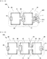
- Figure 1A is a diagram for explaining a dialysis system 100 according to a first embodiment during treatment
- Figure 1B is a diagram for explaining the dialysis system 100 according to the first embodiment during regeneration.
- the dialysis system 100 is a blood purification apparatus for performing hemodialysis treatment.
- the dialysis system 100 performs hemodialysis by guiding the blood of the patient 200 to the dialyzer 30, which is external of the patient's body, and returning purified blood to the body of the patient 200.
- the dialysis system 100 is equipped with a dialysate circulation unit 20 which is connected to the blood circulation unit 10 via the dialyzer 30, an adsorber 40 (adsorption column) having a porous body, and a regenerating water flow unit 50, as illustrated in Figure 1A and Figure 1B .
- a dialysate circulation unit 20 which is connected to the blood circulation unit 10 via the dialyzer 30, an adsorber 40 (adsorption column) having a porous body, and a regenerating water flow unit 50, as illustrated in Figure 1A and Figure 1B .
- the blood circulation unit 10 is a component for circulating blood between a shunt 210 which is applied to the body of the patient 200 and the dialyzer 30 which is provided external of the body of the patient 200.
- the blood circulation unit 10 includes an arterial blood circuit 12 and a venous blood circuit 13 that connect the dialyzer 30 to the shunt 210 via a first connection unit 11.
- functional units such as a blood pump, a supplemental fluid supply line, an anticoagulant injection unit, an air trap chamber, a measuring instrument, and a monitoring device, which are not illustrated, are provided in the blood circulation unit 10 as appropriate.
- the dialyzer 30 is an artificial kidney that purifies the blood of the patient 200 by exchanging substances between the blood of the patient 200 and a dialysate through the operations of diffusion and filtration through a semipermeable membrane.
- the dialyzer 30 is, for example, that in which a plurality of fine tubes formed by a semipermeable membrane, through which the blood of the patient 200 passes, are covered with a cylindrical body through which the dialysate passes, as a component of the dialysate circulation unit 20.
- the dialysate circulation unit 20 is a component for circulating the dialysate between the dialyzer 30 and the adsorber 40.
- the dialysate circulation section 20 includes dialysate circuits 21 and 22 that connect the adsorber 40 to the dialyzer 30 via a third connection (not illustrated).
- functional units such as a dialysate pump, a dialysate supply line, a balance chamber, a heater, a drainage line, a measuring device, a monitoring device, and a dialysate control apparatus, which are not illustrated, are provided in the dialysate circulation unit 20 as appropriate.
- the adsorber 40 includes a porous body which is capable of directly adsorbing uremic substances. That is, the adsorber 40 is an adsorber that can directly adsorb uremic substances. Accordingly, in the present embodiment, it is not practically necessary for the adsorber 40 to have an enzyme for decomposing urea, such as urease. Accordingly, in the present specification, the "adsorber 40 not having an enzyme" means that the adsorber 40 is practically free of an enzyme for decomposing urea.
- the expression "practically free of an enzyme for decomposing urea” means that an aspect that contains an enzyme for decomposing urea in an amount that does not practically function (for example, if an amount of urea which is adsorbed by the porous body is designated as X [g] and the amount of urea decomposed by an enzyme is designated as Y [g], the aspect is that in which Y/(X+Y) ⁇ 0.1) is not excluded. Note that in the following, it is assumed that the adsorber 40 does not contain any enzymes, including an enzyme for decomposing urea or an enzyme for another use, but may contain a small amount of an enzyme for another use.
- the adsorber 40 may include a layer of the porous body which is capable of directly adsorbing uremic substances and layers of other elements.
- the layers of the other elements may contain enzymes.
- the "adsorber not having an enzyme" refers to the portion of the porous body layer which is capable of directly adsorbing the uremic substances in the adsorber 40.
- a carbon based adsorbent is an example of the porous body which is capable of directly adsorbing a uremic substance.
- the carbon based adsorbent may be, for example, an aggregate of natural products having a porous structure such as activated carbon particles, or an aggregate of formed products having a porous structure such as beads that have pores with an average pore diameter of about 8 nm.
- the adsorber 40 has the carbon based adsorbent, the adsorbed uremic substance can be easily desorbed (removed) with regenerating water. Accordingly, it is possible for the adsorber 40 to be regenerated.
- the uremic substances include urea, creatinine, potassium, etc.
- the regenerating water is water that practically does not contain urea.
- the regenerating water include: a liquid in which urea which is contained in utilized regenerating water has been electrolyzed; RO water; physiological saline; unused dialysate, or tap water. Tap water is utilized after being disinfected as appropriate.
- the urea is removed by electrolysis as will be described later.
- the liquid, obtained by electrolyzing urea which is contained in the utilized regenerating water contains urea at a certain concentration.
- the lower the concentration of urea contained in the regenerating water the higher the regeneration ability (the ability to desorb urea from the adsorber 40) will become.
- the adsorber 40 does not have an enzyme for decomposing urea. Therefore, it is not necessary to add or exchange enzymes in order to regenerate the activity of the enzymes that decreases accompanying the decomposition of urea over time. Therefore, the adsorber 40 can be maintained in a fixed state in the dialysate circulation unit 20, and the dialysis system 100, that is, the blood purification apparatus, can be made compact.
- the regenerating water flow unit 50 is a flow channel for causing regenerating water to flow from a regenerating water control apparatus 51 to the adsorber 40.
- the first embodiment will be described as an example of a flow channel in which the regenerating water flow unit 50 circulates regenerating water by causing regenerating water to flow from the regenerating water control apparatus 51 to the adsorber 40 and returning the regenerating water to the regenerating water control apparatus 51.
- the regenerating water flow unit 50 may be a flow channel that causes fresh regenerating water, which is supplied by waterworks, etc., to the adsorber 40 and then discharges the regenerating water without circulating it, to discard the regenerating water. That is, the regenerating water flow unit 50 may be a flow channel that causes regenerating water to flow to the adsorber 40 without passing through the regenerating water control apparatus 51 and additionally without circulating the regenerating water.
- the regenerating water control apparatus 51 is connected to respective connection switching units 41 at the upstream side of the adsorber 40 (the side at which the dialysate containing the uremic substance flows into the adsorber 40) and the downstream side (the side at which the dialysate from which uremic substances are desorbed flows out from the adsorber 40) via regenerating water circuits 54 and 55.
- the regenerating water circuits 54 and 55 may be equipped with second connection units 52 (not illustrated in Figure 1 ; refer to Figure 2B ) which are capable of being connected to the respective connection switching units 41 on the upstream side and the downstream side of the adsorber 40.
- the regenerating water flow unit 50 is provided with functional units such as a regenerating water supply line, a regenerating water pump, and a drain line, as appropriate.
- the regenerating water flow unit 50 is equipped with an electrolytic tank 53 for electrolyzing desorbed urea, that is, urea which is contained in the utilized regenerating water that flows in the regenerating water flow unit 50.
- the electrolytic tank 53 stores a portion of the regenerating water that circulates in the regenerating water flow unit 50 and causes DC current to flow to a portion of the stored regenerating water in order to electrolyze urea, which is dissolved in the regenerating water by being desorbed from the adsorber 40 and is a urotoxin.
- the electrolytic tank 53 includes a gas discharge unit for discharging gas which is generated by electrolysis.
- the adsorbed urea which is a urotoxin
- the amount of regenerating water which is generally about 18 liters, can be reduced approximately 1 liter, for example.
- the amount of regenerating water which is generally utilized is approximately 18 liters as a result of calculating the amount which is required when the regenerating water is caused to flow at a flow rate of 50 mL/min for 6 hours.
- the regenerating water flow unit 50 is connectable to the adsorber 40.
- the adsorber 40 is equipped with the connection switching units 41 that have the function of switching valves that switch the connection between the regenerating water flow unit 50 and the dialysate circulation unit 20 on the upstream side and the downstream side of the dialysate circulation unit 20, respectively.
- connection switching units 41 cut off the connection with the regenerating water flow unit 50 when connected to the dialysate circulation unit 20, and cut off the connection with the dialysate circulation unit 20 when connected to the regenerating water flow unit 50.
- the regenerating water flow unit 50 may be connectable to the connection switching unit 41 of the adsorber 40 by the second connection unit 52 which is provided in the regenerating water circuits 54 and 55. Thereby, the adsorber 40 can be disconnected from the dialysate circuits 21 and 22 of the dialysate circulation unit 20 and connected to the regenerating water circuits 54 and 55 of the regenerating water flow section 50 between a dialysis step and a regeneration step.
- the regenerating water flow unit 50 is connectable to the adsorber 40 in this manner, it is possible for the regenerating water flow unit 50 that includes the regenerating water control apparatus 51 to be separated from the dialysate circulation unit 20. Therefore, as illustrated in Figure 1A , during treatment, a space for installing the regenerating water flow unit 50 that includes the regenerating water control apparatus 51 adjacent to the dialysate circulation unit 20 is unnecessary, and it is only necessary to secure a space for installing each of the functional units which are provided in the blood circulation unit 10 and the dialysate circulation unit 20. Accordingly, the dialysis system 100, that is, the blood purification device can be made compact and can be easily installed in different locations.
- the method for regenerating the adsorber 40 according to the present embodiment can be applied to the regeneration of the adsorber 40 having the porous body.
- the first connection unit 11 of the blood circulation unit 10 is connected to the shunt 210 of the patient 200, and the adsorber 40 having the porous body is connected to the dialysate circulation unit 20. Uremic substances which are present in a dialysate is adsorbed to the adsorber 40 (dialysis step).
- the first connection unit 11 is a component for connecting the arterial blood circuit 12 and the venous blood circuit 13 of the blood circulation unit 10 to the shunt 210 of the patient 200, and directly pierces the shunt 210 of the patient 200.
- the first connection unit 11 is equipped with a piercing needle (not shown), and a shunt connector (not shown) for detachably connecting the piercing needle to the arterial blood circuit 12 and the venous blood circuit 13.
- connection between the adsorber 40 and the regenerating water flow unit 50 is switched and connected to the dialysate circulation section 20 by the connection switching section 41, and a dialysate control appartus (not shown) is driven.
- a dialysate control appartus (not shown) is driven.
- the circulation unit to which the adsorber 40 is connected is switched from the dialysate circulation unit 20 to the regenerating water flow unit 50 by the connection switching unit 41.
- the adsorber 40 may be separated from the dialysate circulation unit 20, and then the connection switching unit 41 of the adsorber 40 may be switched to a connection with the regeneratingwater flow unit 50 thereafter.
- the regenerating water control apparatus 51 is driven, and the uremic substances which are adsorbed on the adsorber 40 are desorbed by the regenerating water that flows through the regenerating water flow unit 50 (regenerating step).
- This regenerating step desorbs the uremic substances which are adsorbed on the adsorber.
- the adsorber 40 and the regenerating water flow unit 50 that includes the regenerating water circuits 54 and 55 is cleansed and/or disinfected by heating, etc. (cleansing/disinfecting step).
- cleaning/disinfecting step As an alternative to disinfection by heating, disinfection by a chemical solution (sodium hypochlorite, peracetic acid, etc.) may be conducted.
- the adsorber 40 and the regenerating water flow unit 50 that includes the regenerating water circuits 54 and 55 may be independently cleansed and/or disinfected. Thereby, the regenerating water flow unit 50 can be reused.
- dialysate circulation unit 20 that includes the dialysate circuits 21 and 22 may be cleansed and/or disinfected in the cleansing/disinfecting step in addition to the regenerating water flow unit 50. Thereby, the regenerating water stream 50 and the dialysate circulation unit 20 can be reused.
- the dialysate circulation unit 20 and the blood circulation unit 10 that includes the dialyzer 30, the arterial blood circuit 12, and the venous blood circuit 13 may be cleansed and/or disinfected in the cleansing/disinfecting step in addition to the regenerating water flow unit 50.
- the regenerating water flow unit 50, the dialysate circulation unit 20, and the blood circulation unit 10 can be reused.
- the adsorber 40 is connected to the dialysate circulation unit 20 to execute the dialysis step again.
- the uremic substances which are adsorbed on the adsorber 40 can be desorbed and the adsorber 40 can be regenerated. Therefore, it is not necessary to separate the desorber 40 from the dialysate circulation unit 20, the configuration of the dialysis system 100 need not be complex, and the operation for regenerating the adsorber 40 is simplified. Further, because the adsorber 40 can be regenerated a plurality of times by repeating the dialysis step and the regenerating step, it is not necessary to separate the desorber 40 from the dialysate circulation unit 20, the configuration of the dialysis system 100 need not be complex, and the operation for regenerating the adsorber 40 is simplified.
- second embodiment differs from the first embodiment mainly in the point that the regenerating water flow unit 50 is connectable to the first connection unit 11.
- the regeneration method during regeneration differs between the second embodiment and the first embodiment. Descriptions of points which are the same as those of the first embodiment may be omitted.
- Figure 2A is a diagram for explaining a dialysis system 100 according to the second embodiment during treatment
- Figure 2B is a diagram for explaining the dialysis system 100 according to the second embodiment during regeneration.
- the dialysis system 100 of the second embodiment is equipped with a dialysate circulation unit 20 which is connected to a blood circulation unit 10 via a dialyzer 30, an adsorber 40 (adsorption column) having a porous body, and a regenerating water flow unit 50, as illustrated in Figure 2A and Figure 2B .
- a dialysate circulation unit 20 which is connected to a blood circulation unit 10 via a dialyzer 30, an adsorber 40 (adsorption column) having a porous body, and a regenerating water flow unit 50, as illustrated in Figure 2A and Figure 2B .
- the regenerating water flow unit 50 is connectable to the first connection unit 11, which is for connecting blood circuits 12 and 13 of a blood circulation unit 10 to a shunt 210, as shown in the change from the state which is illustrated in Figure 2A to the state which is illustrated in Figure 2B .
- the regenerating water flow unit 50 is indirectly connectable to the adsorber 40 through the blood circulation unit 10 that includes the first connection unit 10, and a dialysate circulation unit 20.
- the regenerating water flow unit 50 is also indirectly connectable to the adsorber 40 by utilizing the first connection unit 11 for connecting to the shunt 210.
- the adsorber 40 does not require a special structure, such as a connection switching unit 41 for switching between a connection with the regenerating water flow unit 50 and a connection with the dialysate circulation unit 20. Accordingly, the configuration of the adsorber 40 can be simplified.
- the method for regenerating the adsorber 40 according to the present embodiment can be applied to the regeneration of the adsorber 40 having the porous body.
- the first connection unit 11 of the blood circulation unit 10 is connected to the shunt 210 of the patient 200, and the adsorber 40 having the porous body is connected to the dialysate circulation unit 20.
- Uremic substances which are present in a dialysate is adsorbed to the adsorber 40 (dialysis step). in a manner similar to the method for regenerating the adsorber 40 that employs the dialysis system 100 of the first embodiment.
- a dialysate control appartus (not shown), which is provided in the dialysate circulation unit 20 to which the adsorber 40 is connected, is driven.
- the uremic substances which are present in the blood of the patient 200 are adsorbed onto the adsorber 40, and the blood of the patient 200 is purified.
- the adsorber 40 in the dialysate circulation unit 20 is indirectly connected to the regenerating water flow unit 50 via the blood circulation unit 10. That is, the connection of the first connection unit 11 for connecting with the shunt 210 is switched to a connection with the regenerating water flow unit 50.
- the first connection unit 11 of the blood circulation unit 10 is removed from the shunt 210 of the patient 200 and connected with a second connection unit 52 of the regenerating water flow unit 50.
- the adsorber 40 is indirectly connected to the regenerating water flow unit 50 via the dialysate circulation unit 20 and the blood circulation unit 10.
- blood during treatment flows in order from the shunt 210, the arterial piercing needle, the arterial blood circuit 12, the dialyzer 30, the venous blood circuit 13, the venous piercing needle, and to the shunt 210.
- the shunt 210 and the arterial piercing needle, a shunt connector between the arterial piercing needle and the arterial blood circuit 12, the arterial blood circuit 12 and the dialyzer 30, the dialyzer 30 and the venous blood circuit 13, the shunt connector between the venous blood circuit 13 and the venous piercing needle, and the shunt connector between the venous piercing needle and the shunt 210 are attachable and detachable.
- the arterial blood circuit 12 may be detached from the arterial piercing needle
- the venous blood circuit 13 may be detached from the venous piercing needle
- the arterial blood circuit 12 and the venous blood circuit 13 may be connected to the piercing needles
- the blood circulation unit. 10 may be connected to the second connection unit 52 of the regenerating water flow part 50 via a shunt connector which is provided between the piercing needles and the blood circulation unit 10.
- the arterial piercing needle and the venous piercing needle may be withdrawn from the shunt 210, and the arterial piercing needle and the venous piercing needle may be directly connected to the second connection unit 52 of the regenerating water flow unit 50.
- a regenerating water control apparatus 51 is driven, and uremic substances which are adsorbed on the adsorber 40 are desorbed by regenerating water that flows through the regenerating water flow unit 50 (regeneration step).
- the dialysate circulation unit 20 that includes the adsorber 40, the blood circulation unit 10, and the regenerating water flow unit 50 are cleansed and/or disinfected by heating, etc. (cleansing/disinfecting step).
- cleaning/disinfecting step disinfection by heating, disinfection by a chemical solution (sodium hypochlorite, peracetic acid, etc.) may be conducted.
- the regenerating water flow unit 50, the dialysate circulation unit 20, and the blood circulating nit 10 can be reused.
- the adsorber 40 is connected to the shunt 210 of the patient 200 via the dialysate circulation unit 20 and the first connection unit 11 of the blood circulation unit 10 to execute the dialysis step again.
- the method for regenerating the adsorber 40 according to the second embodiment utilizes the first connection unit 11 of the blood circulation unit 10 in the manner described above, and therefore, compared to the method for regenerating the adsorber 40 according to the first embodiment, the method for regenerating the adsorber 40 according to the second embodiment is more effective than that of the first embodiment, because there is no switching step for switching the connection by the connection switching unit 41 of the adsorber 40 between the connection with the regenerating water flow unit 50 and the connection with the dialysate circulation unit 20. Therefore, the connection switching unit 41 is not necessary in the the adsorber 40, and the operations involved in regeneration of the adsorber 40 can be simplified, and the configuration of the dialysis system 100 can be simplified.
- the uremic substance adsorbed on the adsorber 40 can be desorbed and the adsorber 40 can be regenerated. There is no need to disconnect, the dialysis system 100 can be simplified, and the operation for regenerating the adsorber 40 is simplified. Further, because the adsorber 40 can be regenerated a plurality of times by repeating the dialysis step and the regenerating step, there is no need to separate the adsorber 40 from the dialysate circulation unit 20, the dialysis system 100 can be simplified, and the operation for regenerating the adsorber 40 is simplified.
- the adsorber 40 which has a porous body and does not have an enzyme is regenerated.
- the dialysis step in which the adsorber 40 is connected to the dialysate circulation unit 20 to adsorb uremic substances onto the adsorber 40 and, after the dialysis step, the regeneration step in which the uremic substances which are adsorbed on the adsorber 40 are desorbed by the regenerating water that flows through the regenerating water flow unit 50 are repeated.
- the regenerating water flow unit 50 can be spatially separated during treatment.
- the dialysis system 100 can be made compact during treatment.
- the blood purification apparatus which is constituted by the dialysate circulation unit 20 and the blood circulation unit 10, excluding the regenerating water flow unit 50, can be easily installed in different locations.
- the dialysis system 100 is equipped with the dialysate circulation unit 20 and the adsorber 40 that is connected to the dialysate circulation unit 20 and has a porous body and does not have an enzyme. Because the regenerating water flow unit 50 is connectable to the adsorber 40, the regenerating water flow unit 50 can be spatially separated during treatment.
- the dialysis system 100 during treatment can be made more compact compared to a dialysis system that presumes that desorption of the uremic substances (regeneration of the adsorber 40) is performed simultaneously with treatment.
- the blood purification apparatus that includes the dialysate circulation unit 20 and the blood circulation unit 10, excluding the regenerating water flow unit 50, can be made compact, and the blood purification device can be easily installed in different locations.
- the method for regenerating the adsorber 40 according to the present embodiment can be applied to the regeneration of the adsorber 40 having a porous body.
- the regeneration method of the adsorber 40 according to the present embodiment is different from the method for regenerating the adsorber described as the first embodiment in that the cleaning/disinfecting step after the regeneration step can be omitted or simplified.
- the method for regenerating the adsorber 40 according to the present embodiment will be described in detail with reference to Figure. 1A and Figure 1B again.
- the first connection unit 11 of the blood circulation unit 10 is connected to the shunt 210 of the patient 200.
- the adsorber 40 having a porous body is connected to the dialysate circulation unit 20 to adsorb uremic substances in the dialysate onto the adsorber 40 (dialysis step), as illustrated in Figure 1A .
- the circulation unit to which the adsorber 40 is connected is switched to the regenerating water flow unit 50 from the dialysate circulation unit 20 by the connection switching unit 41, as illustrated in Figure 1B .
- the adsorber 40 may be separated from the dialysate circulation unit 20, and then the connection switching unit 41 of the adsorber 40 may switch to the connection with the regenerating water flow unit 50 thereafter.
- the regenerating water control apparatus 51 is driven to desorb the uremic substances which are adsorbed on the adsorber 40 by the regenerating water that flows through the regenerating water flow unit 50 (regeneration step).
- water that contains chloride ions is utilized as the regenerating water.
- the concentration of chloride ions is adapted to ensure a necessary amount of the amount of hypochlorous acid to be described later, and may be, for example, equal to the concentration of chloride ions in physiological saline. Therefore, physiological saline may be utilized as the regenerating water.
- This regeneration step desorbs the uremic substance which are adsorbed on the adsorber 40.
- the regenerating water that flows in the regenerating water flow section 50 during the regeneration step is electrolyzed in the electrolytic tank 53.
- chloride ions which are contained in the regenerating water are oxidized by electrodes to generate hypochlorous acid. That is, when the regenerating water is electrolyzed, urea is electrolyzed and hypochlorous acid is generated.
- hypochlorous acid is generated during the regeneration step in this manner.
- Hypochlorous acid as is widely known, is capable of being decomposed in aqueous solutions and can be utilized as a disinfectant. Therefore, in the present embodiment, the hypochlorous acid in the regenerating water can function as a disinfectant. Specifically, during the regeneration step as well, because the regenerating water that contains the hypochlorous acid flows through the regenerating water flow unit 50, the regenerating water flow unit 50 can be disinfected.
- the adsorber 40 and the regenerating water flow unit 50 that includes the regenerating water circuits 54 and 55 is cleansed and/or disinfected by heating, etc. (cleansing/disinfecting step).
- cleaning/disinfecting step disinfection by heating, disinfection by a chemical solution (sodium hypochlorite, peracetic acid, etc.) may be conducted.
- the adsorber 40 and the regenerating water flow unit 50 that includes the regenerating water circuits 54 and 55 may be independently cleansed and/or disinfected. Thereby, the regenerating water flow unit 50 can be reused.
- the regenerating water flow unit 50 can be disinfected by utilizing hypochlorous acid which is generated as a byproduct when urea is electrolyzed, as described above. Therefore, it is possible to omit or simplify the cleansing/disinfecting step after the regenerating step described in (5).
- the dialysate circulation unit 20 that includes the dialysate circuits 21 and 22 may be cleansed and/or disinfected in the cleansing/disinfecting step in addition to the regenerating water flow unit 50. Thereby, the regenerating water stream 50 and the dialysate circulation unit 20 can be reused.
- the dialysate circulation unit 20 and the blood circulation unit 10 that includes the dialyzer 30, the arterial blood circuit 12, and the venous blood circuit 13 may be cleansed and/or disinfected in the cleansing/disinfecting step in addition to the regenerating water flow unit 50. Thereby, the regenerating water flow unit 50, the dialysate circulation unit 20, and the blood circulation unit 10 can be reused.
- the adsorber 40 is connected to the dialysate circulation unit 20 to execute the dialysis step again.
- the same effects as those of the first embodiment described above can be obtained by the third embodiment.
- the regenerating water flow unit 50 can be disinfected utilizing the hypochlorous acid, it is possible to omit or simplify the cleansing/disinfecting step after the regenerating step (in particular, the cleansing/disinfecting step related to the regenerating water flow unit 50).
- the method for regenerating the adsorber 40 according to the present embodiment can be applied to the regeneration of the adsorber 40 having a porous body.
- the regeneration method of the adsorber 40 according to the present embodiment is different from the method for regenerating the adsorber described as the second embodiment in that the cleaning/disinfecting step after the regeneration step can be omitted or simplified.
- the method for regenerating the adsorber 40 according to the present embodiment will be described in detail with reference to Figure. 2A and Figure 2B again.
- the first connection unit 11 of the blood circulation unit 10 is connected to the shunt 210 of the patient 200.
- the adsorber 40 having a porous body is connected to the dialysate circulation unit 20 to adsorb uremic substances in the dialysate onto the adsorber 40 (dialysis step), as illustrated in Figure 2A .
- the adsorber 40 in the dialysate circulation unit 20 is indirectly connected to the regenerating water flow unit 50 via the blood circulation unit 10, as illustrated in Figure 2B . That is, the first connection unit 11 for connecting with the shunt 210 is switched from a connection with the shunt 210 to a connection with the regenerating water flow unit 50.
- the regenerating water control apparatus 51 is driven to desorb the uremic substances which are adsorbed on the adsorber 40 by the regenerating water that flows through the regenerating water flow unit 50 (regeneration step).
- water that contains chloride ions is utilized as the regenerating water.
- the concentration of chloride ions is adapted to ensure a necessary amount of the amount of hypochlorous acid to be described later, and may be, for example, equal to the concentration of chloride ions in physiological saline. Therefore, physiological saline may be utilized as the regenerating water.
- This regeneration step desorbs the uremic substances which are adsorbed on the adsorber 40.
- hypochlorous acid is generated during the regeneration step in this manner.
- Hypochlorous acid as is widely known, is capable of being decomposed in aqueous solutions and can be utilized as a disinfectant. Therefore, in the present embodiment, the hypochlorous acid in the regenerating water can function as a disinfectant. Specifically, during the regeneration step as well, because the regenerating water that contains the hypochlorous acid flows through the regenerating water flow unit 50, the regenerating water flow unit 50 can be disinfected.
- the blood circulation unit 10 is connected to the regenerating water flow unit 50 as illustrated in Figure 2B . Therefore, the arterial blood circuit 12 and the venous blood circuit 13 within the blood circulation unit 10 can be disinfected by the hypochlorous acid which is contained in the regenerating water in addition to the regenerating water circuits 54 and 55 within the regenerating water flow unit 50.
- the dialyzer 30 which is connected to the blood circulation unit 10 can also be disinfected.
- the regenerating water that reaches the dialyzer 30 via the blood circulation unit 10 can further flow to the dialysate circulation unit 20 via the dialyzer 30.
- the dialysate circuit 21, etc. within the dialysate circulation unit 20 can be disinfected by the hypochlorous acid which is contained in the regenerating water.
- the dialysate circulation unit 20 that includes adsorber 40, the blood circulation unit 10, and the regenerating water flow unit 50 are cleansed and/or disinfected by heating, etc. (cleansing/disinfecting step).
- cleaning/disinfecting step disinfection by heating, disinfection by a chemical solution (sodium hypochlorite, peracetic acid, etc.) may be conducted.
- the regenerating water flow unit 50, the dialysate circulation unit 20, and the blood circulation unit 10 can be reused.
- the dialysate circulation unit 20, the blood circulation unit 10, and the regenerating water flow unit 50 can be disinfected by utilizing hypochlorous acid which is generated as a byproduct when urea is electrolyzed, as described above. Therefore, it is possible to omit or simplify the cleansing/disinfecting step after the regenerating step described in (5).
- the adsorber 40 is connected to shunt 210 of the patient 200 via the dialysate circulation unit 20 and the blood circulation unit 10 to execute the dialysis step again.
- the same effects as those of the second embodiment described above can be obtained by the fourth embodiment.
- the fourth embodiment by utilizing water that contains chloride ions as the regenerating water, it is possible to generate hypochlorous acid as a byproduct during the regeneration step when urea is electrolyzed. Because the dialysate circulation unit 20, the blood circulation unit 10, and the regenerating water flow unit 50 can be disinfected by utilizing the hypochlorous acid, it is possible to omit or greatly simplify the cleansing/disinfecting step after the regenerating step.
- Figure 3 is a graph that shows the results of a urea electrolysis test.
- the horizontal axis represents processing time, and the vertical axis represents the concentration of urea.
- Temporal change properties in a column entrance concentration and temporal change properties in a column exit concentration are indicated.
- test conditions were as follows.
- the column entrance concentration is the concentration of urea in the regenerating water immediately prior to passing through the column
- the column exit concentration is the concentration of urea in the regenerating water immediately following passing through the column.
- the column entrance concentration decreases rapidly after processing is initiated. From this, it can be understood that electrolysis of urea is being efficiently realized.
- the initial value of the column entrance concentration (the value when processing is initiated) is the same as the initial value of the column exit concentration (the value when processing is initiated), and is a concentration that substantially corresponds to the concentration of urea which is employed in the simulated treatment (75 mg/dL). From this, it can be understood that desorption of urea from the column is initiated immediately by the regenerating water.
- the column exit concentration decreases as the processing progresses (as the processing time increases). From this, it can be understood that the urea which is adsorbed on the column decreases accompanying desorption of urea from the column by the regenerating water passing through the column. When the urea which is adsorbed on the column is substantially eliminated, the column exit concentration becomes approximately zero, and the column entrance concentration also becomes approximately zero. In this case, if the processing time becomes approximately seven hours, the column exit concentration and the column entrance concentration become approximately zero, and a state in which continued processing will not practically contribute to regeneration of the column is reached.
- the difference between the temporal change properties of the column entrance concentration and the temporal change properties of the column exit concentration corresponds to the concentration of urea which is removed from the column. Accordingly, the temporally integrated value of the difference between these two curves correlates to the total amount of urea removed from the column. From the results shown in FIG. 3 , when the total amount of urea removed from the column was calculated, it almost coincided with the total amount of urea which was adsorbed on the column. Therefore, substantially all of the urea which was adsorbed on the column was removed, and it was confirmed that the column was regenerated. That is, the effectiveness of the embodiment described above was confirmed.
Landscapes
- Health & Medical Sciences (AREA)
- Heart & Thoracic Surgery (AREA)
- Urology & Nephrology (AREA)
- Vascular Medicine (AREA)
- Hematology (AREA)
- Veterinary Medicine (AREA)
- Anesthesiology (AREA)
- Biomedical Technology (AREA)
- Engineering & Computer Science (AREA)
- Life Sciences & Earth Sciences (AREA)
- Animal Behavior & Ethology (AREA)
- General Health & Medical Sciences (AREA)
- Public Health (AREA)
- Emergency Medicine (AREA)
- Chemical & Material Sciences (AREA)
- Chemical Kinetics & Catalysis (AREA)
- General Chemical & Material Sciences (AREA)
- Cardiology (AREA)
- External Artificial Organs (AREA)
Abstract
Description
- The present disclosure is related to a method for regenerating an adsorber and a dialysis system.
- Conventionally, there is a method for removing harmful substances from a blood filtrate in an ultrafiltration type blood purification apparatus.
- The method for removing harmful substances employs two or more adsorbers which are filled with nitrogen containing fibrous activated carbon adsorbent alternately or in a predetermined order to adsorb harmful substances with one or more adsorbers. Harmful substances are desorbed (regeneration of the adsorber) from the one or more adsorbers which have adsorbed the harmful substances and are not currently being utilized for adsorption. That is, adsorption of the harmful substances by the adsorbers and desorption of the harmful substances from the adsorbers are alternately conducted during treatment in which a patient's blood is circulated through an ultrafiltration membrane refer to Patent Document 1).
- [Patent Document 1] Japanese Examined Application Publication No.
S64-9029 - The method for removing harmful substances from adsorbers in a conventional conventional blood purification apparatus requires a large and complex apparatus, and it is difficult to change the installation location of such a blood purification apparatus.
- According to one aspect of the present disclosure, a method for regenerating an adsorber, which has a porous body and does not have an enzyme, is provided. The method for regenerating an adsorber includes:
- a dialysis step in which the adsorber is connected to a dialysate circulation unit to adsorb uremic substances in a dialysate onto the adsorber; and
- a regenerating step following the dialysis step, in which the uremic substances which are adsorbed onto the adsorber are removed by regenerating water that flows in a regenerating water flow unit.
- According to the present disclosure, it is possible to provide a method for regenerating an adsorber and a dialysis system that facilitates changing installation locations of a blood purification apparatus.
-
-
Figure 1A is a diagram for explaining a dialysis system according to a first embodiment during treatment. -
Figure 1B is a diagram for explaining the dialysis system according to the first embodiment during regeneration. -
Figure 2A is a diagram for explaining a dialysis system according to a second embodiment during treatment. -
Figure 2B is a diagram for explaining the dialysis system according to the second embodiment during regeneration. -
Figure 3 is a graph that shows the results of a urea electrolysis test. - Hereinafter, embodiments will be described in detail with reference to the attached drawings.
- Hereinafter, a first aspect (hereinafter, referred to as "first embodiment") will be described in detail with reference to the drawings. Note that the same elements will be denoted by the same reference numbers or reference symbols throughout the entirety of the description of the embodiments. Note that in the following description, unless otherwise specified, the term "treatment" refers to a state in which the blood of a
patient 200 is being circulated through adialyzer 30 in ablood circulation unit 10, and the term "regeneration" refers to a state in which the blood of thepatient 200 is not being circulated in theblood circulation unit 10. Note that although the present embodiment shows an example applied to hemodialysis, the present disclosure is not limited to such a configuration. The present disclosure may be applied to all blood purification treatments such as hemofiltration and hemofiltration dialysis. Note that in the following description, the term "dialysis" refers to dialysis treatment. -
Figure 1A is a diagram for explaining adialysis system 100 according to a first embodiment during treatment, andFigure 1B is a diagram for explaining thedialysis system 100 according to the first embodiment during regeneration. - The
dialysis system 100 according to the first embodiment is a blood purification apparatus for performing hemodialysis treatment. Thedialysis system 100 performs hemodialysis by guiding the blood of thepatient 200 to thedialyzer 30, which is external of the patient's body, and returning purified blood to the body of thepatient 200. - In greater detail, the
dialysis system 100 is equipped with adialysate circulation unit 20 which is connected to theblood circulation unit 10 via thedialyzer 30, an adsorber 40 (adsorption column) having a porous body, and a regeneratingwater flow unit 50, as illustrated inFigure 1A and Figure 1B . - The
blood circulation unit 10 is a component for circulating blood between ashunt 210 which is applied to the body of thepatient 200 and thedialyzer 30 which is provided external of the body of thepatient 200. Theblood circulation unit 10 includes anarterial blood circuit 12 and avenous blood circuit 13 that connect thedialyzer 30 to theshunt 210 via afirst connection unit 11. In addition, functional units such as a blood pump, a supplemental fluid supply line, an anticoagulant injection unit, an air trap chamber, a measuring instrument, and a monitoring device, which are not illustrated, are provided in theblood circulation unit 10 as appropriate. - The
dialyzer 30 is an artificial kidney that purifies the blood of thepatient 200 by exchanging substances between the blood of thepatient 200 and a dialysate through the operations of diffusion and filtration through a semipermeable membrane. Thedialyzer 30 is, for example, that in which a plurality of fine tubes formed by a semipermeable membrane, through which the blood of thepatient 200 passes, are covered with a cylindrical body through which the dialysate passes, as a component of thedialysate circulation unit 20. - The
dialysate circulation unit 20 is a component for circulating the dialysate between thedialyzer 30 and theadsorber 40. Thedialysate circulation section 20 includesdialysate circuits adsorber 40 to thedialyzer 30 via a third connection (not illustrated). In addition, functional units such as a dialysate pump, a dialysate supply line, a balance chamber, a heater, a drainage line, a measuring device, a monitoring device, and a dialysate control apparatus, which are not illustrated, are provided in thedialysate circulation unit 20 as appropriate. - The
adsorber 40 includes a porous body which is capable of directly adsorbing uremic substances. That is, theadsorber 40 is an adsorber that can directly adsorb uremic substances. Accordingly, in the present embodiment, it is not practically necessary for theadsorber 40 to have an enzyme for decomposing urea, such as urease. Accordingly, in the present specification, the "adsorber 40 not having an enzyme" means that theadsorber 40 is practically free of an enzyme for decomposing urea. The expression "practically free of an enzyme for decomposing urea" means that an aspect that contains an enzyme for decomposing urea in an amount that does not practically function (for example, if an amount of urea which is adsorbed by the porous body is designated as X [g] and the amount of urea decomposed by an enzyme is designated as Y [g], the aspect is that in which Y/(X+Y)≤0.1) is not excluded. Note that in the following, it is assumed that theadsorber 40 does not contain any enzymes, including an enzyme for decomposing urea or an enzyme for another use, but may contain a small amount of an enzyme for another use. - In addition, the
adsorber 40 may include a layer of the porous body which is capable of directly adsorbing uremic substances and layers of other elements. In this case, the layers of the other elements may contain enzymes. In this case, the "adsorber not having an enzyme" refers to the portion of the porous body layer which is capable of directly adsorbing the uremic substances in theadsorber 40. - A carbon based adsorbent is an example of the porous body which is capable of directly adsorbing a uremic substance. The carbon based adsorbent may be, for example, an aggregate of natural products having a porous structure such as activated carbon particles, or an aggregate of formed products having a porous structure such as beads that have pores with an average pore diameter of about 8 nm. As described above, because the
adsorber 40 has the carbon based adsorbent, the adsorbed uremic substance can be easily desorbed (removed) with regenerating water. Accordingly, it is possible for theadsorber 40 to be regenerated. Here, the uremic substances include urea, creatinine, potassium, etc. - Here, the regenerating water is water that practically does not contain urea. Examples of the regenerating water include: a liquid in which urea which is contained in utilized regenerating water has been electrolyzed; RO water; physiological saline; unused dialysate, or tap water. Tap water is utilized after being disinfected as appropriate. Note that with respect to the regenerating water that contains urea which is desorbed from the
adsorber 40, the urea is removed by electrolysis as will be described later. However, there are cases in which it is difficult to completely remove urea at this time. Therefore, there are cases in which the liquid, obtained by electrolyzing urea which is contained in the utilized regenerating water, contains urea at a certain concentration. In addition, basically, the lower the concentration of urea contained in the regenerating water, the higher the regeneration ability (the ability to desorb urea from the adsorber 40) will become. - In addition, the
adsorber 40 does not have an enzyme for decomposing urea. Therefore, it is not necessary to add or exchange enzymes in order to regenerate the activity of the enzymes that decreases accompanying the decomposition of urea over time. Therefore, theadsorber 40 can be maintained in a fixed state in thedialysate circulation unit 20, and thedialysis system 100, that is, the blood purification apparatus, can be made compact. - The regenerating
water flow unit 50 is a flow channel for causing regenerating water to flow from a regeneratingwater control apparatus 51 to theadsorber 40. Note that the first embodiment will be described as an example of a flow channel in which the regeneratingwater flow unit 50 circulates regenerating water by causing regenerating water to flow from the regeneratingwater control apparatus 51 to theadsorber 40 and returning the regenerating water to the regeneratingwater control apparatus 51. Alternatively, the regeneratingwater flow unit 50 may be a flow channel that causes fresh regenerating water, which is supplied by waterworks, etc., to theadsorber 40 and then discharges the regenerating water without circulating it, to discard the regenerating water. That is, the regeneratingwater flow unit 50 may be a flow channel that causes regenerating water to flow to theadsorber 40 without passing through the regeneratingwater control apparatus 51 and additionally without circulating the regenerating water. - The regenerating
water control apparatus 51 is connected to respectiveconnection switching units 41 at the upstream side of the adsorber 40 (the side at which the dialysate containing the uremic substance flows into the adsorber 40) and the downstream side (the side at which the dialysate from which uremic substances are desorbed flows out from the adsorber 40) via regeneratingwater circuits water circuits Figure 1 ; refer toFigure 2B ) which are capable of being connected to the respectiveconnection switching units 41 on the upstream side and the downstream side of theadsorber 40. In addition, the regeneratingwater flow unit 50 is provided with functional units such as a regenerating water supply line, a regenerating water pump, and a drain line, as appropriate. - In addition, the regenerating
water flow unit 50 is equipped with anelectrolytic tank 53 for electrolyzing desorbed urea, that is, urea which is contained in the utilized regenerating water that flows in the regeneratingwater flow unit 50. Specifically, theelectrolytic tank 53 stores a portion of the regenerating water that circulates in the regeneratingwater flow unit 50 and causes DC current to flow to a portion of the stored regenerating water in order to electrolyze urea, which is dissolved in the regenerating water by being desorbed from theadsorber 40 and is a urotoxin. Note that theelectrolytic tank 53 includes a gas discharge unit for discharging gas which is generated by electrolysis. - Thereby, the adsorbed urea, which is a urotoxin, can be effectively dissolved, so that the amount of regenerating water, which is generally about 18 liters, can be reduced approximately 1 liter, for example. In addition, the amount of regenerating water which is generally utilized is approximately 18 liters as a result of calculating the amount which is required when the regenerating water is caused to flow at a flow rate of 50 mL/min for 6 hours. In the case of the embodiment that includes the
electrolytic tank 53, it is only necessary for a priming volume (filling amount) of theadsorber 40 and the other components to be satisfied. Therefore, it is possible to reduce the volume of the required amount of regenerating water to approximately 1 liter. - Here, as shown in the change from the state illustrated in
Figure 1A to the state illustrated inFigure 1B , the regeneratingwater flow unit 50 is connectable to theadsorber 40. Specifically, for example, theadsorber 40 is equipped with theconnection switching units 41 that have the function of switching valves that switch the connection between the regeneratingwater flow unit 50 and thedialysate circulation unit 20 on the upstream side and the downstream side of thedialysate circulation unit 20, respectively. - The
connection switching units 41 cut off the connection with the regeneratingwater flow unit 50 when connected to thedialysate circulation unit 20, and cut off the connection with thedialysate circulation unit 20 when connected to the regeneratingwater flow unit 50. - Note that the regenerating
water flow unit 50 may be connectable to theconnection switching unit 41 of theadsorber 40 by thesecond connection unit 52 which is provided in the regeneratingwater circuits adsorber 40 can be disconnected from thedialysate circuits dialysate circulation unit 20 and connected to the regeneratingwater circuits water flow section 50 between a dialysis step and a regeneration step. - Because the regenerating
water flow unit 50 is connectable to theadsorber 40 in this manner, it is possible for the regeneratingwater flow unit 50 that includes the regeneratingwater control apparatus 51 to be separated from thedialysate circulation unit 20. Therefore, as illustrated inFigure 1A , during treatment, a space for installing the regeneratingwater flow unit 50 that includes the regeneratingwater control apparatus 51 adjacent to thedialysate circulation unit 20 is unnecessary, and it is only necessary to secure a space for installing each of the functional units which are provided in theblood circulation unit 10 and thedialysate circulation unit 20. Accordingly, thedialysis system 100, that is, the blood purification device can be made compact and can be easily installed in different locations. - Next, a method for regenerating the
adsorber 40 that employs thedialysis system 100 of the first embodiment will be described. - The method for regenerating the
adsorber 40 according to the present embodiment can be applied to the regeneration of theadsorber 40 having the porous body. - (1) First, as illustrated in
Figure 1A , thefirst connection unit 11 of theblood circulation unit 10 is connected to theshunt 210 of thepatient 200, and theadsorber 40 having the porous body is connected to thedialysate circulation unit 20. Uremic substances which are present in a dialysate is adsorbed to the adsorber 40 (dialysis step). Thefirst connection unit 11 is a component for connecting thearterial blood circuit 12 and thevenous blood circuit 13 of theblood circulation unit 10 to theshunt 210 of thepatient 200, and directly pierces theshunt 210 of thepatient 200. Thefirst connection unit 11 is equipped with a piercing needle (not shown), and a shunt connector (not shown) for detachably connecting the piercing needle to thearterial blood circuit 12 and thevenous blood circuit 13. - Specifically, the connection between the
adsorber 40 and the regeneratingwater flow unit 50 is switched and connected to thedialysate circulation section 20 by theconnection switching section 41, and a dialysate control appartus (not shown) is driven. By this dialysis step, the uremic substances which are present in the blood of thepatient 200 are adsorbed onto theadsorber 40, and the blood of thepatient 200 is purified. - (2) Next, as illustrated in
Figure 1B , the circulation unit to which theadsorber 40 is connected is switched from thedialysate circulation unit 20 to the regeneratingwater flow unit 50 by theconnection switching unit 41. Note that theadsorber 40 may be separated from thedialysate circulation unit 20, and then theconnection switching unit 41 of theadsorber 40 may be switched to a connection with theregeneratingwater flow unit 50 thereafter. - (3) Then, after the dialysis step, the regenerating
water control apparatus 51 is driven, and the uremic substances which are adsorbed on theadsorber 40 are desorbed by the regenerating water that flows through the regenerating water flow unit 50 (regenerating step). - This regenerating step desorbs the uremic substances which are adsorbed on the adsorber.
- (4) The regenerating water that flows through the regenerating
water flow unit 50 during the regeneration step is electrolyzed. - (5) Subsequently, after the regeneration step, the
adsorber 40 and the regeneratingwater flow unit 50 that includes the regeneratingwater circuits - In the cleansing/disinfecting step, the
adsorber 40 and the regeneratingwater flow unit 50 that includes the regeneratingwater circuits water flow unit 50 can be reused. - Further, the
dialysate circulation unit 20 that includes thedialysate circuits water flow unit 50. Thereby, the regeneratingwater stream 50 and thedialysate circulation unit 20 can be reused. - Still further, the
dialysate circulation unit 20 and theblood circulation unit 10 that includes thedialyzer 30, thearterial blood circuit 12, and thevenous blood circuit 13 may be cleansed and/or disinfected in the cleansing/disinfecting step in addition to the regeneratingwater flow unit 50. Thereby, the regeneratingwater flow unit 50, thedialysate circulation unit 20, and theblood circulation unit 10 can be reused. - (6) The
adsorber 40 is connected to thedialysate circulation unit 20 to execute the dialysis step again. - (7) The dialysis step and the regeneration step are alternately repeated.
- By performing the regeneration step after performing the dialysis step in this manner, the uremic substances which are adsorbed on the
adsorber 40 can be desorbed and theadsorber 40 can be regenerated. Therefore, it is not necessary to separate the desorber 40 from thedialysate circulation unit 20, the configuration of thedialysis system 100 need not be complex, and the operation for regenerating theadsorber 40 is simplified. Further, because theadsorber 40 can be regenerated a plurality of times by repeating the dialysis step and the regenerating step, it is not necessary to separate the desorber 40 from thedialysate circulation unit 20, the configuration of thedialysis system 100 need not be complex, and the operation for regenerating theadsorber 40 is simplified. - Note that because there is a cleansing/disinfecting step between the regeneration step and the next dialysis step, not only RO water but also ordinary water such as non-disinfected tap water may be utilized as the regenerating water. Because tap water supplied from waterworks may be utilized, there are advantages that transport is not required as in the case that water stored in a physiological saline solution bag is utilized, and an RO water manufacturing apparatus is not required as in the case that RO water is utilized. It is only necessary to connect the
dialysis system 100 to waterworks, which is simple. - Next, a second aspect (hereinafter, referred to as "second embodiment") will be described in detail with reference to the drawings. The second embodiment differs from the first embodiment mainly in the point that the regenerating
water flow unit 50 is connectable to thefirst connection unit 11. In addition, the regeneration method during regeneration differs between the second embodiment and the first embodiment. Descriptions of points which are the same as those of the first embodiment may be omitted. -
Figure 2A is a diagram for explaining adialysis system 100 according to the second embodiment during treatment, andFigure 2B is a diagram for explaining thedialysis system 100 according to the second embodiment during regeneration. - Similarly to the
dialysis system 100 of the first embodiment, thedialysis system 100 of the second embodiment is equipped with adialysate circulation unit 20 which is connected to ablood circulation unit 10 via adialyzer 30, an adsorber 40 (adsorption column) having a porous body, and a regeneratingwater flow unit 50, as illustrated inFigure 2A and Figure 2B . - However, more specifically, the regenerating
water flow unit 50 is connectable to thefirst connection unit 11, which is for connectingblood circuits blood circulation unit 10 to ashunt 210, as shown in the change from the state which is illustrated inFigure 2A to the state which is illustrated inFigure 2B . Thereby, the regeneratingwater flow unit 50 is indirectly connectable to theadsorber 40 through theblood circulation unit 10 that includes thefirst connection unit 10, and adialysate circulation unit 20. In addition, the regeneratingwater flow unit 50 is also indirectly connectable to theadsorber 40 by utilizing thefirst connection unit 11 for connecting to theshunt 210. Therefore, theadsorber 40 does not require a special structure, such as aconnection switching unit 41 for switching between a connection with the regeneratingwater flow unit 50 and a connection with thedialysate circulation unit 20. Accordingly, the configuration of theadsorber 40 can be simplified. - Next, a method for regenerating the
adsorber 40 that employs thedialysis system 100 of the second embodiment will be described. - The method for regenerating the
adsorber 40 according to the present embodiment can be applied to the regeneration of theadsorber 40 having the porous body. - (1) First, as illustrated in
Figure 2A , thefirst connection unit 11 of theblood circulation unit 10 is connected to theshunt 210 of thepatient 200, and theadsorber 40 having the porous body is connected to thedialysate circulation unit 20. Uremic substances which are present in a dialysate is adsorbed to the adsorber 40 (dialysis step). in a manner similar to the method for regenerating theadsorber 40 that employs thedialysis system 100 of the first embodiment. - Specifically, a dialysate control appartus (not shown), which is provided in the
dialysate circulation unit 20 to which theadsorber 40 is connected, is driven. By this dialysis step, the uremic substances which are present in the blood of thepatient 200 are adsorbed onto theadsorber 40, and the blood of thepatient 200 is purified. - (2) Next, following the dialysis step, the
adsorber 40 in thedialysate circulation unit 20 is indirectly connected to the regeneratingwater flow unit 50 via theblood circulation unit 10. That is, the connection of thefirst connection unit 11 for connecting with theshunt 210 is switched to a connection with the regeneratingwater flow unit 50. - Specifically, the
first connection unit 11 of theblood circulation unit 10 is removed from theshunt 210 of thepatient 200 and connected with asecond connection unit 52 of the regeneratingwater flow unit 50. Thereby, theadsorber 40 is indirectly connected to the regeneratingwater flow unit 50 via thedialysate circulation unit 20 and theblood circulation unit 10. - Here, in greater detail, blood during treatment flows in order from the
shunt 210, the arterial piercing needle, thearterial blood circuit 12, thedialyzer 30, thevenous blood circuit 13, the venous piercing needle, and to theshunt 210. Theshunt 210 and the arterial piercing needle, a shunt connector between the arterial piercing needle and thearterial blood circuit 12, thearterial blood circuit 12 and thedialyzer 30, thedialyzer 30 and thevenous blood circuit 13, the shunt connector between thevenous blood circuit 13 and the venous piercing needle, and the shunt connector between the venous piercing needle and theshunt 210 are attachable and detachable. For this reason, for example, thearterial blood circuit 12 may be detached from the arterial piercing needle, thevenous blood circuit 13 may be detached from the venous piercing needle, thearterial blood circuit 12 and thevenous blood circuit 13 may be connected to the piercing needles, and the blood circulation unit. 10 may be connected to thesecond connection unit 52 of the regeneratingwater flow part 50 via a shunt connector which is provided between the piercing needles and theblood circulation unit 10. In addition, for example, the arterial piercing needle and the venous piercing needle may be withdrawn from theshunt 210, and the arterial piercing needle and the venous piercing needle may be directly connected to thesecond connection unit 52 of the regeneratingwater flow unit 50. - (3) Next, following the dialysis step, a regenerating
water control apparatus 51 is driven, and uremic substances which are adsorbed on theadsorber 40 are desorbed by regenerating water that flows through the regenerating water flow unit 50 (regeneration step). - (4) The regenerating water that flows through the regenerating
water flow unit 50 during the regeneration step is electrolyzed. - (5) Subsequently, after the regeneration step, the
dialysate circulation unit 20 that includes theadsorber 40, theblood circulation unit 10, and the regeneratingwater flow unit 50 are cleansed and/or disinfected by heating, etc. (cleansing/disinfecting step). Note that as an alternative to disinfection by heating, disinfection by a chemical solution (sodium hypochlorite, peracetic acid, etc.) may be conducted. Thereby, the regeneratingwater flow unit 50, thedialysate circulation unit 20, and theblood circulating nit 10 can be reused. - (6) The
adsorber 40 is connected to theshunt 210 of thepatient 200 via thedialysate circulation unit 20 and thefirst connection unit 11 of theblood circulation unit 10 to execute the dialysis step again. - (7) The dialysis step and the regeneration step are alternately repeated.
- The method for regenerating the
adsorber 40 according to the second embodiment utilizes thefirst connection unit 11 of theblood circulation unit 10 in the manner described above, and therefore, compared to the method for regenerating theadsorber 40 according to the first embodiment, the method for regenerating theadsorber 40 according to the second embodiment is more effective than that of the first embodiment, because there is no switching step for switching the connection by theconnection switching unit 41 of theadsorber 40 between the connection with the regeneratingwater flow unit 50 and the connection with thedialysate circulation unit 20. Therefore, theconnection switching unit 41 is not necessary in the theadsorber 40, and the operations involved in regeneration of theadsorber 40 can be simplified, and the configuration of thedialysis system 100 can be simplified. - Further, after the dialysis step is performed, by performing the regeneration step, the uremic substance adsorbed on the
adsorber 40 can be desorbed and theadsorber 40 can be regenerated. There is no need to disconnect, thedialysis system 100 can be simplified, and the operation for regenerating theadsorber 40 is simplified. Further, because theadsorber 40 can be regenerated a plurality of times by repeating the dialysis step and the regenerating step, there is no need to separate the adsorber 40 from thedialysate circulation unit 20, thedialysis system 100 can be simplified, and the operation for regenerating theadsorber 40 is simplified. - According to the method for regenerating the
adsorber 40, theadsorber 40 which has a porous body and does not have an enzyme is regenerated. The dialysis step in which theadsorber 40 is connected to thedialysate circulation unit 20 to adsorb uremic substances onto theadsorber 40 and, after the dialysis step, the regeneration step in which the uremic substances which are adsorbed on theadsorber 40 are desorbed by the regenerating water that flows through the regeneratingwater flow unit 50 are repeated. The regeneratingwater flow unit 50 can be spatially separated during treatment. Compared particularly to a dialysis system that presumes that desorption of uremic substances from the adsorber 40 (regeneration of the adsorber 40) is performed simultaneously during treatment, thedialysis system 100 can be made compact during treatment. In addition, the blood purification apparatus which is constituted by thedialysate circulation unit 20 and theblood circulation unit 10, excluding the regeneratingwater flow unit 50, can be easily installed in different locations. - According to the
dialysis system 100, thedialysis system 100 is equipped with thedialysate circulation unit 20 and theadsorber 40 that is connected to thedialysate circulation unit 20 and has a porous body and does not have an enzyme. Because the regeneratingwater flow unit 50 is connectable to theadsorber 40, the regeneratingwater flow unit 50 can be spatially separated during treatment. Thedialysis system 100 during treatment can be made more compact compared to a dialysis system that presumes that desorption of the uremic substances (regeneration of the adsorber 40) is performed simultaneously with treatment. The blood purification apparatus that includes thedialysate circulation unit 20 and theblood circulation unit 10, excluding the regeneratingwater flow unit 50, can be made compact, and the blood purification device can be easily installed in different locations. - Next, an embodiment, in which the
dialysis system 100 of the first embodiment described above is not changed, but the method for regenerating the adsorber of the first embodiment is changed, will be described as a third embodiment. - The method for regenerating the
adsorber 40 according to the present embodiment can be applied to the regeneration of theadsorber 40 having a porous body. The regeneration method of theadsorber 40 according to the present embodiment is different from the method for regenerating the adsorber described as the first embodiment in that the cleaning/disinfecting step after the regeneration step can be omitted or simplified. Hereinafter, the method for regenerating theadsorber 40 according to the present embodiment will be described in detail with reference toFigure. 1A and Figure 1B again. - (1) First, in a manner similar to the method for regenerating the
adsorber 40 that employs thedialysis system 100 of the first embodiment described above, thefirst connection unit 11 of theblood circulation unit 10 is connected to theshunt 210 of thepatient 200. Theadsorber 40 having a porous body is connected to thedialysate circulation unit 20 to adsorb uremic substances in the dialysate onto the adsorber 40 (dialysis step), as illustrated inFigure 1A . - (2) Next, in a manner similar to the method for regenerating the
adsorber 40 that employs thedialysis system 100 of the first embodiment, the circulation unit to which theadsorber 40 is connected is switched to the regeneratingwater flow unit 50 from thedialysate circulation unit 20 by theconnection switching unit 41, as illustrated inFigure 1B . Note that theadsorber 40 may be separated from thedialysate circulation unit 20, and then theconnection switching unit 41 of theadsorber 40 may switch to the connection with the regeneratingwater flow unit 50 thereafter. - (3) Then, after the dialysis step, the regenerating
water control apparatus 51 is driven to desorb the uremic substances which are adsorbed on theadsorber 40 by the regenerating water that flows through the regenerating water flow unit 50 (regeneration step). At this time, in the present embodiment, water that contains chloride ions is utilized as the regenerating water. The concentration of chloride ions is adapted to ensure a necessary amount of the amount of hypochlorous acid to be described later, and may be, for example, equal to the concentration of chloride ions in physiological saline. Therefore, physiological saline may be utilized as the regenerating water. - This regeneration step desorbs the uremic substance which are adsorbed on the
adsorber 40. - (4) The regenerating water that flows in the regenerating
water flow section 50 during the regeneration step is electrolyzed in theelectrolytic tank 53. At this time, chloride ions which are contained in the regenerating water are oxidized by electrodes to generate hypochlorous acid. That is, when the regenerating water is electrolyzed, urea is electrolyzed and hypochlorous acid is generated. - In the present embodiment, hypochlorous acid is generated during the regeneration step in this manner. Hypochlorous acid, as is widely known, is capable of being decomposed in aqueous solutions and can be utilized as a disinfectant. Therefore, in the present embodiment, the hypochlorous acid in the regenerating water can function as a disinfectant. Specifically, during the regeneration step as well, because the regenerating water that contains the hypochlorous acid flows through the regenerating
water flow unit 50, the regeneratingwater flow unit 50 can be disinfected. - (5) Subsequently, after the regeneration step, the
adsorber 40 and the regeneratingwater flow unit 50 that includes the regeneratingwater circuits - In the cleansing/disinfecting step, the
adsorber 40 and the regeneratingwater flow unit 50 that includes the regeneratingwater circuits water flow unit 50 can be reused. - However, in the present embodiment, during the regeneration step, the regenerating
water flow unit 50 can be disinfected by utilizing hypochlorous acid which is generated as a byproduct when urea is electrolyzed, as described above. Therefore, it is possible to omit or simplify the cleansing/disinfecting step after the regenerating step described in (5). - Note that in the present embodiment as well, the
dialysate circulation unit 20 that includes thedialysate circuits water flow unit 50. Thereby, the regeneratingwater stream 50 and thedialysate circulation unit 20 can be reused. - Further, the
dialysate circulation unit 20 and theblood circulation unit 10 that includes thedialyzer 30, thearterial blood circuit 12, and thevenous blood circuit 13 may be cleansed and/or disinfected in the cleansing/disinfecting step in addition to the regeneratingwater flow unit 50. Thereby, the regeneratingwater flow unit 50, thedialysate circulation unit 20, and theblood circulation unit 10 can be reused. - (6) The
adsorber 40 is connected to thedialysate circulation unit 20 to execute the dialysis step again. - (7) The dialysis step and the regeneration step are alternately repeated.
- In this manner, the same effects as those of the first embodiment described above can be obtained by the third embodiment. Further, according to the third embodiment, by utilizing water that contains chloride ions as the regenerating water, it is possible to generate hypochlorous acid as a byproduct during the regeneration step when urea is electrolyzed. In addition, because the regenerating
water flow unit 50 can be disinfected utilizing the hypochlorous acid, it is possible to omit or simplify the cleansing/disinfecting step after the regenerating step (in particular, the cleansing/disinfecting step related to the regenerating water flow unit 50). - Next, an embodiment, in which the
dialysis system 100 of the second embodiment described above is not changed, but the method for regenerating the adsorber of the second embodiment is changed, will be described as a fourth embodiment. - The method for regenerating the
adsorber 40 according to the present embodiment can be applied to the regeneration of theadsorber 40 having a porous body. The regeneration method of theadsorber 40 according to the present embodiment is different from the method for regenerating the adsorber described as the second embodiment in that the cleaning/disinfecting step after the regeneration step can be omitted or simplified. Hereinafter, the method for regenerating theadsorber 40 according to the present embodiment will be described in detail with reference toFigure. 2A and Figure 2B again. - (1) First, in a manner similar to the method for regenerating the
adsorber 40 that employs thedialysis system 100 of the second embodiment described above, thefirst connection unit 11 of theblood circulation unit 10 is connected to theshunt 210 of thepatient 200. Theadsorber 40 having a porous body is connected to thedialysate circulation unit 20 to adsorb uremic substances in the dialysate onto the adsorber 40 (dialysis step), as illustrated inFigure 2A . - (2) Next, in a manner similar to the method for regenerating the
adsorber 40 that employs thedialysis system 100 of the second embodiment, theadsorber 40 in thedialysate circulation unit 20 is indirectly connected to the regeneratingwater flow unit 50 via theblood circulation unit 10, as illustrated inFigure 2B . That is, thefirst connection unit 11 for connecting with theshunt 210 is switched from a connection with theshunt 210 to a connection with the regeneratingwater flow unit 50. - (3) Then, after the dialysis step, the regenerating
water control apparatus 51 is driven to desorb the uremic substances which are adsorbed on theadsorber 40 by the regenerating water that flows through the regenerating water flow unit 50 (regeneration step). At this time, in the present embodiment, water that contains chloride ions is utilized as the regenerating water. The concentration of chloride ions is adapted to ensure a necessary amount of the amount of hypochlorous acid to be described later, and may be, for example, equal to the concentration of chloride ions in physiological saline. Therefore, physiological saline may be utilized as the regenerating water. - This regeneration step desorbs the uremic substances which are adsorbed on the
adsorber 40. - (4) The regenerating water that flows in the regenerating
water flow section 50 during the regeneration step is electrolyzed in theelectrolytic tank 53. At this time, chloride ions which are contained in the regenerating water are oxidized by electrodes to generate hypochlorous acid. With regard to this point, it is the same as the case of the third embodiment described above. - In the present embodiment, hypochlorous acid is generated during the regeneration step in this manner. Hypochlorous acid, as is widely known, is capable of being decomposed in aqueous solutions and can be utilized as a disinfectant. Therefore, in the present embodiment, the hypochlorous acid in the regenerating water can function as a disinfectant. Specifically, during the regeneration step as well, because the regenerating water that contains the hypochlorous acid flows through the regenerating
water flow unit 50, the regeneratingwater flow unit 50 can be disinfected. - Here, in the present embodiment, the
blood circulation unit 10 is connected to the regeneratingwater flow unit 50 as illustrated inFigure 2B . Therefore, thearterial blood circuit 12 and thevenous blood circuit 13 within theblood circulation unit 10 can be disinfected by the hypochlorous acid which is contained in the regenerating water in addition to the regeneratingwater circuits water flow unit 50. In addition, thedialyzer 30 which is connected to theblood circulation unit 10 can also be disinfected. Further, the regenerating water that reaches thedialyzer 30 via theblood circulation unit 10 can further flow to thedialysate circulation unit 20 via thedialyzer 30. Accordingly, in the present embodiment, thedialysate circuit 21, etc. within thedialysate circulation unit 20 can be disinfected by the hypochlorous acid which is contained in the regenerating water. - (5) Subsequently, after the regeneration step, the
dialysate circulation unit 20 that includesadsorber 40, theblood circulation unit 10, and the regeneratingwater flow unit 50 are cleansed and/or disinfected by heating, etc. (cleansing/disinfecting step). Note that as an alternative to disinfection by heating, disinfection by a chemical solution (sodium hypochlorite, peracetic acid, etc.) may be conducted. Thereby, the regeneratingwater flow unit 50, thedialysate circulation unit 20, and theblood circulation unit 10 can be reused. - However, in the present embodiment, during the regeneration step, the
dialysate circulation unit 20, theblood circulation unit 10, and the regeneratingwater flow unit 50 can be disinfected by utilizing hypochlorous acid which is generated as a byproduct when urea is electrolyzed, as described above. Therefore, it is possible to omit or simplify the cleansing/disinfecting step after the regenerating step described in (5). - (6) The
adsorber 40 is connected to shunt 210 of thepatient 200 via thedialysate circulation unit 20 and theblood circulation unit 10 to execute the dialysis step again. - (7) The dialysis step and the regeneration step are alternately repeated.
- In this manner, the same effects as those of the second embodiment described above can be obtained by the fourth embodiment. In addition, according to the fourth embodiment, by utilizing water that contains chloride ions as the regenerating water, it is possible to generate hypochlorous acid as a byproduct during the regeneration step when urea is electrolyzed. Because the
dialysate circulation unit 20, theblood circulation unit 10, and the regeneratingwater flow unit 50 can be disinfected by utilizing the hypochlorous acid, it is possible to omit or greatly simplify the cleansing/disinfecting step after the regenerating step. - Next, the results of a test of electrolyzing urea will be described with reference to
Figure 3 . -
Figure 3 is a graph that shows the results of a urea electrolysis test. InFigure 3 , the horizontal axis represents processing time, and the vertical axis represents the concentration of urea. Temporal change properties in a column entrance concentration and temporal change properties in a column exit concentration are indicated. - The test conditions were as follows.
- (1) A stock solution as the regenerating water described above was a physiological saline solution (a 0.9% sodium chloride aqueous solution), and the amount was 1 liter.
- (2) A column as a porous body of the
adsorber 40 was a columnar shape having a diameter of 120 mm and a height of 210 mm, and filled with 2300 ml of an adsorbent. In addition, the column had urea, etc. adsorbed thereon in advance by a simulated treatment (urea concentration of 75 mg/dL). The direction of flow of the stock solution with respect to the column was from bottom to top. - (3) Regarding the
electrolytic tank 53, the material of both an anode and a cathode was platinum coated titanium. The electrode area was 662 cm2 for the anode and 607 cm2 for the cathode, and the applied voltage was 5 V direct current. - (4) A tube pump was used as a regenerating water pump, and the flow rate was 50 mL/min.
- (5) The stock solution as the regenerating water passed through the column, was subjected to electrolysis in the
electrolytic tank 53, and was utilized again in a circulation system to pass through the column again. - In
Figure 3 , the column entrance concentration is the concentration of urea in the regenerating water immediately prior to passing through the column, and the column exit concentration is the concentration of urea in the regenerating water immediately following passing through the column. - As shown in
Figure 3 , the column entrance concentration decreases rapidly after processing is initiated. From this, it can be understood that electrolysis of urea is being efficiently realized. Note that the initial value of the column entrance concentration (the value when processing is initiated) is the same as the initial value of the column exit concentration (the value when processing is initiated), and is a concentration that substantially corresponds to the concentration of urea which is employed in the simulated treatment (75 mg/dL). From this, it can be understood that desorption of urea from the column is initiated immediately by the regenerating water. - From
Figure 3 , it can be understood that the column exit concentration decreases as the processing progresses (as the processing time increases). From this, it can be understood that the urea which is adsorbed on the column decreases accompanying desorption of urea from the column by the regenerating water passing through the column. When the urea which is adsorbed on the column is substantially eliminated, the column exit concentration becomes approximately zero, and the column entrance concentration also becomes approximately zero. In this case, if the processing time becomes approximately seven hours, the column exit concentration and the column entrance concentration become approximately zero, and a state in which continued processing will not practically contribute to regeneration of the column is reached. - Here, the difference between the temporal change properties of the column entrance concentration and the temporal change properties of the column exit concentration corresponds to the concentration of urea which is removed from the column. Accordingly, the temporally integrated value of the difference between these two curves correlates to the total amount of urea removed from the column. From the results shown in
FIG. 3 , when the total amount of urea removed from the column was calculated, it almost coincided with the total amount of urea which was adsorbed on the column. Therefore, substantially all of the urea which was adsorbed on the column was removed, and it was confirmed that the column was regenerated. That is, the effectiveness of the embodiment described above was confirmed. - Embodiments were described in detail above. However, the present disclosure is not limited to any specific embodiments, and various change and modifications are possible within the scopes which are recited in the claims. In addition, it is also possible to entirely or partially combine the constituent elements of the embodiments which are described above.
-
- 10
- blood circulation unit
- 11
- first connection unit
- 12
- arterial blood circuit
- 13
- venous blood circuit
- 20
- dialysate circulation unit
- 21
- dialysate circuit
- 22
- dialysate circuit
- 30
- dialyzer
- 40
- adsorber
- 41
- connection switching unit
- 50
- regenerating water flow unit
- 51
- regenerating water control apparatus
- 52
- second connection unit
- 53
- electrolytic tank
- 54
- regenerating water circuit
- 55
- regenerating water circuit
- 100
- dialysis system
- 200
- patient
- 210
- shunt
Claims (12)
- A method for regenerating an adsorber, which has a porous body and does not have an enzyme, comprising:a dialysis step in which the adsorber is connected to a dialysate circulation unit to adsorb uremic substances in a dialysate onto the adsorber; anda regenerating step following the dialysis step, in which the uremic substances which are adsorbed on the adsorber are removed by regenerating water that flows in a regenerating water flow unit.
- The method for regenerating an adsorber as defined in Claim 1, further comprising:
a cleansing/disinfecting step, in which the regenerating water flow unit is cleansed and/or disinfected. - The method for regenerating an adsorber as defined in Claim 2, wherein:
the cleansing/disinfecting step cleanses and/or disinfects a dialysate circuit and a dialyzer in the dialysate circulation unit. - The method for regenerating an adsorber as defined in Claim 2, wherein:
the cleansing/disinfecting step cleanses and/or disinfects a blood circuit in a blood circulation unit. - The method for regenerating an adsorber as defined in any one of Claims 1 through 4, wherein:
the regenerating step electrolyzes urea which is contained in the regenerating water that flows in the regenerating water flow unit. - The method for regenerating an adsorber as defined in Claim 5, wherein:the regenerating step comprises causing water that contains chloride ions to flow in the regenerating water flow unit as the regenerating water; andhypochlorous acid is generated during electrolysis of the urea.
- The method for regenerating an adsorber as defined in any one of Claims 1 through 6, wherein:
a circulation unit to which the adsorber is connected is switched from the dialysate circulation unit to the regenerating water flow unit between the dialysis step and the regenerating step. - The method for regenerating an adsorber as defined in any one of Claims 1 through 7, wherein:
the adsorber is separated from the dialysate circulation unit and connected to the regenerating water flow unit between the dialysis step and the regenerating step. - The method for regenerating an adsorber as definedin anyone of CLamis 1 through 7, wherein:
a connection of a first connection unit for connecting a blood circuit of a blood circulation unit to a shunt is switched from a connection with the shunt to a connection to the regenerating water flow unit between the dialysis step and the regenerating step. - A dialysis system, comprising:a dialysate circulation unit; andan adsorber which is connected to the dialysate circulation unit, having a porous body and not having an enzyme; the dialysis system further comprising:a regenerating water flow unit; wherein:the regenerating water flow unit is connectable to the adsorber.
- A dialysis system as defined in Claim 10, wherein:
the regenerating water flow unit is connectable to a first connection unit for connecting a blood circuit of a blood circulation unit to a shunt. - A dialysis system as defined in either one of Claim 10 and Claim 11, wherein:
the regenerating water flow unit comprises an electrolytic tank for electrolyzing urea which is contained in regenerating water that flows in the regenerating water flow unit.
Applications Claiming Priority (2)
| Application Number | Priority Date | Filing Date | Title |
|---|---|---|---|
| JP2017228862 | 2017-11-29 | ||
| PCT/JP2018/043600 WO2019107357A1 (en) | 2017-11-29 | 2018-11-27 | Adsorber regeneration method and dialysis system |
Publications (3)
| Publication Number | Publication Date |
|---|---|
| EP3677292A1 true EP3677292A1 (en) | 2020-07-08 |
| EP3677292A4 EP3677292A4 (en) | 2021-05-19 |
| EP3677292B1 EP3677292B1 (en) | 2025-05-21 |
Family
ID=66664008
Family Applications (1)
| Application Number | Title | Priority Date | Filing Date |
|---|---|---|---|
| EP18882395.9A Active EP3677292B1 (en) | 2017-11-29 | 2018-11-27 | Method for regenerating adsorber and dialysis system |
Country Status (5)
| Country | Link |
|---|---|
| US (2) | US11583619B2 (en) |
| EP (1) | EP3677292B1 (en) |
| JP (1) | JP7257964B2 (en) |
| CN (1) | CN111417418B (en) |
| WO (1) | WO2019107357A1 (en) |
Families Citing this family (1)
| Publication number | Priority date | Publication date | Assignee | Title |
|---|---|---|---|---|
| CN113499497B (en) * | 2021-08-13 | 2024-02-23 | 江苏恰瑞生物科技有限公司 | Immobilized enzyme reactant regeneration system and operation method thereof |
Family Cites Families (18)
| Publication number | Priority date | Publication date | Assignee | Title |
|---|---|---|---|---|
| BE792690A (en) * | 1971-12-14 | 1973-06-13 | Rhone Poulenc Sa | PROCESS FOR PURIFYING A CHLORIDE SOLUTION |
| JPS5234154B2 (en) * | 1973-01-16 | 1977-09-01 | ||
| US4118314A (en) * | 1974-01-09 | 1978-10-03 | Seisan Kaihatsu Kagaku Kenkyusho | Apparatus for treatment of artificial kidney dialyzing fluid |
| JPS5538125A (en) | 1978-09-08 | 1980-03-17 | Toho Beslon Co | Artificial kidney device |
| US4857181A (en) | 1986-10-30 | 1989-08-15 | Cobe Laboratories, Inc. | Control of cleaning of dialysate preparation apparatus |
| JPH0245318A (en) | 1988-07-29 | 1990-02-15 | Mitsubishi Heavy Ind Ltd | Bottle holder |
| JP2626401B2 (en) * | 1992-03-06 | 1997-07-02 | 松下電器産業株式会社 | Activated carbon washing and regeneration method and water purification device |
| JP3384040B2 (en) | 1993-07-16 | 2003-03-10 | 宇部興産株式会社 | Biological function assisting / substituting device |
| JPH09327511A (en) * | 1996-06-12 | 1997-12-22 | A S A Sangyo Kk | Method for collecting and regenerating peritoneal dialysis fluid, processing device therefor and accessory |
| JP4003016B2 (en) | 1996-12-18 | 2007-11-07 | 栗田工業株式会社 | Nitrogen compound-containing water treatment method |
| DE19917522A1 (en) | 1999-04-17 | 2000-10-19 | Jms Co Ltd | Blood purification process, comprises separating out the non-cellular components and then subjecting the blood to further cleansing. |
| JP2003251338A (en) | 2002-02-28 | 2003-09-09 | Ideya:Kk | Water treatment apparatus and water purifying apparatus with function for regenerating activated carbon, and water treatment method used for the same |
| DE602007013824D1 (en) * | 2007-12-03 | 2011-05-19 | Hepa Wash Gmbh | Dialysate REGENERATION UNIT |
| CN103889478B (en) * | 2011-08-18 | 2017-03-15 | 弗雷塞尼斯医疗保健控股公司 | Adsorption and chemical regeneration of dialysate |
| EP2804640B1 (en) * | 2012-01-19 | 2016-01-13 | Baxter International Inc | Method and composition for removing uremic toxins in dialysis processes |
| US9974896B2 (en) * | 2014-06-24 | 2018-05-22 | Medtronic, Inc. | Method of zirconium phosphate recharging |
| KR101580439B1 (en) * | 2014-05-08 | 2015-12-24 | 조태범 | Dialysate regeneration unit and blood dialyzing apparatus having the same |
| CN106344985B (en) * | 2016-09-20 | 2018-06-12 | 黄昱 | A kind of multifunctional recycled blood purification system |
-
2018
- 2018-11-27 US US16/768,008 patent/US11583619B2/en active Active
- 2018-11-27 JP JP2019557237A patent/JP7257964B2/en active Active
- 2018-11-27 CN CN201880077494.XA patent/CN111417418B/en active Active
- 2018-11-27 EP EP18882395.9A patent/EP3677292B1/en active Active
- 2018-11-27 WO PCT/JP2018/043600 patent/WO2019107357A1/en not_active Ceased
-
2023
- 2023-01-24 US US18/158,601 patent/US12274820B2/en active Active
Also Published As
| Publication number | Publication date |
|---|---|
| US11583619B2 (en) | 2023-02-21 |
| WO2019107357A1 (en) | 2019-06-06 |
| JPWO2019107357A1 (en) | 2020-11-19 |
| US12274820B2 (en) | 2025-04-15 |
| EP3677292B1 (en) | 2025-05-21 |
| CN111417418B (en) | 2023-09-01 |
| US20200360588A1 (en) | 2020-11-19 |
| EP3677292A4 (en) | 2021-05-19 |
| JP7257964B2 (en) | 2023-04-14 |
| US20230158219A1 (en) | 2023-05-25 |
| CN111417418A (en) | 2020-07-14 |
Similar Documents
| Publication | Publication Date | Title |
|---|---|---|
| JP6499645B2 (en) | Redox controlled electrosorption and decomposition apparatus for purifying blood and other fluids | |
| US9440016B2 (en) | Hemodialysis and peritoneal dialysis systems having electrodialysis and electrodeionization capabilities | |
| CA2754522C (en) | Hemodialysis and peritoneal dialysis systems having electrodeionization capabilities | |
| JP4903583B2 (en) | Portable personal dialysis dialysate regeneration system | |
| US12274820B2 (en) | Method for regenerating adsorber and dialysis system | |
| AU2014242274B2 (en) | Hemodialysis and peritoneal dialysis systems having electrodialysis and electrodeionization capabilities | |
| JP6826852B2 (en) | Blood purification device | |
| US3909377A (en) | Purification of a chloride solution | |
| JP4183036B2 (en) | Blood purification apparatus and regeneration method thereof | |
| JP2994611B2 (en) | How to purify pool water | |
| JP3187756B2 (en) | How to purify pool water | |
| JP2933576B2 (en) | How to purify pool water | |
| US20240016832A1 (en) | Dialysate for hemodialysis | |
| JP2847082B2 (en) | How to purify pool water | |
| RU2290209C2 (en) | Method and device for cleaning dialyzing solution in "artificial kidney' apparatus | |
| ES2973506T3 (en) | Methods and apparatus using permselective diffusion of urea through charged membranes | |
| JPH11207150A (en) | Liquid purifier using live bacterial and liquid purifying device | |
| JPS6320145B2 (en) | ||
| HK1213210B (en) | Hemodialysis and peritoneal dialysis systems having electrodialysis and electrodeionization capabilities |
Legal Events
| Date | Code | Title | Description |
|---|---|---|---|
| STAA | Information on the status of an ep patent application or granted ep patent |
Free format text: STATUS: THE INTERNATIONAL PUBLICATION HAS BEEN MADE |
|
| PUAI | Public reference made under article 153(3) epc to a published international application that has entered the european phase |
Free format text: ORIGINAL CODE: 0009012 |
|
| STAA | Information on the status of an ep patent application or granted ep patent |
Free format text: STATUS: REQUEST FOR EXAMINATION WAS MADE |
|
| 17P | Request for examination filed |
Effective date: 20200331 |
|
| AK | Designated contracting states |
Kind code of ref document: A1 Designated state(s): AL AT BE BG CH CY CZ DE DK EE ES FI FR GB GR HR HU IE IS IT LI LT LU LV MC MK MT NL NO PL PT RO RS SE SI SK SM TR |
|
| AX | Request for extension of the european patent |
Extension state: BA ME |
|
| DAV | Request for validation of the european patent (deleted) | ||
| DAX | Request for extension of the european patent (deleted) | ||
| A4 | Supplementary search report drawn up and despatched |
Effective date: 20210419 |
|
| RIC1 | Information provided on ipc code assigned before grant |
Ipc: A61M 1/16 20060101AFI20210413BHEP |
|
| STAA | Information on the status of an ep patent application or granted ep patent |
Free format text: STATUS: EXAMINATION IS IN PROGRESS |
|
| 17Q | First examination report despatched |
Effective date: 20230301 |
|
| P01 | Opt-out of the competence of the unified patent court (upc) registered |
Effective date: 20230523 |
|
| GRAP | Despatch of communication of intention to grant a patent |
Free format text: ORIGINAL CODE: EPIDOSNIGR1 |
|
| STAA | Information on the status of an ep patent application or granted ep patent |
Free format text: STATUS: GRANT OF PATENT IS INTENDED |
|
| RIN1 | Information on inventor provided before grant (corrected) |
Inventor name: YOKOYAMA, TAKAYOSHI Inventor name: NIMURA, HIROSHI Inventor name: FUJIWARA, MASATO |
|
| INTG | Intention to grant announced |
Effective date: 20250116 |
|
| GRAS | Grant fee paid |
Free format text: ORIGINAL CODE: EPIDOSNIGR3 |
|
| GRAA | (expected) grant |
Free format text: ORIGINAL CODE: 0009210 |
|
| STAA | Information on the status of an ep patent application or granted ep patent |
Free format text: STATUS: THE PATENT HAS BEEN GRANTED |
|
| AK | Designated contracting states |
Kind code of ref document: B1 Designated state(s): AL AT BE BG CH CY CZ DE DK EE ES FI FR GB GR HR HU IE IS IT LI LT LU LV MC MK MT NL NO PL PT RO RS SE SI SK SM TR |
|
| REG | Reference to a national code |
Ref country code: GB Ref legal event code: FG4D |
|
| REG | Reference to a national code |
Ref country code: CH Ref legal event code: EP |
|
| REG | Reference to a national code |
Ref country code: DE Ref legal event code: R096 Ref document number: 602018082189 Country of ref document: DE |
|
| REG | Reference to a national code |
Ref country code: IE Ref legal event code: FG4D |
|
| REG | Reference to a national code |
Ref country code: NL Ref legal event code: MP Effective date: 20250521 |
|
| PG25 | Lapsed in a contracting state [announced via postgrant information from national office to epo] |
Ref country code: FI Free format text: LAPSE BECAUSE OF FAILURE TO SUBMIT A TRANSLATION OF THE DESCRIPTION OR TO PAY THE FEE WITHIN THE PRESCRIBED TIME-LIMIT Effective date: 20250521 Ref country code: PT Free format text: LAPSE BECAUSE OF FAILURE TO SUBMIT A TRANSLATION OF THE DESCRIPTION OR TO PAY THE FEE WITHIN THE PRESCRIBED TIME-LIMIT Effective date: 20250922 Ref country code: ES Free format text: LAPSE BECAUSE OF FAILURE TO SUBMIT A TRANSLATION OF THE DESCRIPTION OR TO PAY THE FEE WITHIN THE PRESCRIBED TIME-LIMIT Effective date: 20250521 |
|
| REG | Reference to a national code |
Ref country code: LT Ref legal event code: MG9D |
|
| PG25 | Lapsed in a contracting state [announced via postgrant information from national office to epo] |
Ref country code: GR Free format text: LAPSE BECAUSE OF FAILURE TO SUBMIT A TRANSLATION OF THE DESCRIPTION OR TO PAY THE FEE WITHIN THE PRESCRIBED TIME-LIMIT Effective date: 20250822 Ref country code: NO Free format text: LAPSE BECAUSE OF FAILURE TO SUBMIT A TRANSLATION OF THE DESCRIPTION OR TO PAY THE FEE WITHIN THE PRESCRIBED TIME-LIMIT Effective date: 20250821 |
|
| PG25 | Lapsed in a contracting state [announced via postgrant information from national office to epo] |
Ref country code: PL Free format text: LAPSE BECAUSE OF FAILURE TO SUBMIT A TRANSLATION OF THE DESCRIPTION OR TO PAY THE FEE WITHIN THE PRESCRIBED TIME-LIMIT Effective date: 20250521 Ref country code: NL Free format text: LAPSE BECAUSE OF FAILURE TO SUBMIT A TRANSLATION OF THE DESCRIPTION OR TO PAY THE FEE WITHIN THE PRESCRIBED TIME-LIMIT Effective date: 20250521 |
|
| PG25 | Lapsed in a contracting state [announced via postgrant information from national office to epo] |
Ref country code: BG Free format text: LAPSE BECAUSE OF FAILURE TO SUBMIT A TRANSLATION OF THE DESCRIPTION OR TO PAY THE FEE WITHIN THE PRESCRIBED TIME-LIMIT Effective date: 20250521 |
|
| PG25 | Lapsed in a contracting state [announced via postgrant information from national office to epo] |
Ref country code: HR Free format text: LAPSE BECAUSE OF FAILURE TO SUBMIT A TRANSLATION OF THE DESCRIPTION OR TO PAY THE FEE WITHIN THE PRESCRIBED TIME-LIMIT Effective date: 20250521 |
|
| PG25 | Lapsed in a contracting state [announced via postgrant information from national office to epo] |
Ref country code: RS Free format text: LAPSE BECAUSE OF FAILURE TO SUBMIT A TRANSLATION OF THE DESCRIPTION OR TO PAY THE FEE WITHIN THE PRESCRIBED TIME-LIMIT Effective date: 20250821 |
|
| PG25 | Lapsed in a contracting state [announced via postgrant information from national office to epo] |
Ref country code: IS Free format text: LAPSE BECAUSE OF FAILURE TO SUBMIT A TRANSLATION OF THE DESCRIPTION OR TO PAY THE FEE WITHIN THE PRESCRIBED TIME-LIMIT Effective date: 20250921 |
|
| PG25 | Lapsed in a contracting state [announced via postgrant information from national office to epo] |
Ref country code: LV Free format text: LAPSE BECAUSE OF FAILURE TO SUBMIT A TRANSLATION OF THE DESCRIPTION OR TO PAY THE FEE WITHIN THE PRESCRIBED TIME-LIMIT Effective date: 20250521 |
|
| REG | Reference to a national code |
Ref country code: AT Ref legal event code: MK05 Ref document number: 1796246 Country of ref document: AT Kind code of ref document: T Effective date: 20250521 |
|
| PGFP | Annual fee paid to national office [announced via postgrant information from national office to epo] |
Ref country code: DE Payment date: 20251127 Year of fee payment: 8 |
|
| PGFP | Annual fee paid to national office [announced via postgrant information from national office to epo] |
Ref country code: GB Payment date: 20251120 Year of fee payment: 8 |
|
| PG25 | Lapsed in a contracting state [announced via postgrant information from national office to epo] |
Ref country code: DK Free format text: LAPSE BECAUSE OF FAILURE TO SUBMIT A TRANSLATION OF THE DESCRIPTION OR TO PAY THE FEE WITHIN THE PRESCRIBED TIME-LIMIT Effective date: 20250521 Ref country code: AT Free format text: LAPSE BECAUSE OF FAILURE TO SUBMIT A TRANSLATION OF THE DESCRIPTION OR TO PAY THE FEE WITHIN THE PRESCRIBED TIME-LIMIT Effective date: 20250521 Ref country code: SM Free format text: LAPSE BECAUSE OF FAILURE TO SUBMIT A TRANSLATION OF THE DESCRIPTION OR TO PAY THE FEE WITHIN THE PRESCRIBED TIME-LIMIT Effective date: 20250521 |
|
| PGFP | Annual fee paid to national office [announced via postgrant information from national office to epo] |
Ref country code: FR Payment date: 20251125 Year of fee payment: 8 |
|
| PG25 | Lapsed in a contracting state [announced via postgrant information from national office to epo] |
Ref country code: CZ Free format text: LAPSE BECAUSE OF FAILURE TO SUBMIT A TRANSLATION OF THE DESCRIPTION OR TO PAY THE FEE WITHIN THE PRESCRIBED TIME-LIMIT Effective date: 20250521 |
|
| PG25 | Lapsed in a contracting state [announced via postgrant information from national office to epo] |
Ref country code: EE Free format text: LAPSE BECAUSE OF FAILURE TO SUBMIT A TRANSLATION OF THE DESCRIPTION OR TO PAY THE FEE WITHIN THE PRESCRIBED TIME-LIMIT Effective date: 20250521 |
|
| PG25 | Lapsed in a contracting state [announced via postgrant information from national office to epo] |
Ref country code: RO Free format text: LAPSE BECAUSE OF FAILURE TO SUBMIT A TRANSLATION OF THE DESCRIPTION OR TO PAY THE FEE WITHIN THE PRESCRIBED TIME-LIMIT Effective date: 20250521 Ref country code: SK Free format text: LAPSE BECAUSE OF FAILURE TO SUBMIT A TRANSLATION OF THE DESCRIPTION OR TO PAY THE FEE WITHIN THE PRESCRIBED TIME-LIMIT Effective date: 20250521 |
|
| PG25 | Lapsed in a contracting state [announced via postgrant information from national office to epo] |
Ref country code: IT Free format text: LAPSE BECAUSE OF FAILURE TO SUBMIT A TRANSLATION OF THE DESCRIPTION OR TO PAY THE FEE WITHIN THE PRESCRIBED TIME-LIMIT Effective date: 20250521 |
|
| REG | Reference to a national code |
Ref country code: DE Ref legal event code: R097 Ref document number: 602018082189 Country of ref document: DE |
|
| PLBE | No opposition filed within time limit |
Free format text: ORIGINAL CODE: 0009261 |
|
| STAA | Information on the status of an ep patent application or granted ep patent |
Free format text: STATUS: NO OPPOSITION FILED WITHIN TIME LIMIT |
|
| REG | Reference to a national code |
Ref country code: CH Ref legal event code: L10 Free format text: ST27 STATUS EVENT CODE: U-0-0-L10-L00 (AS PROVIDED BY THE NATIONAL OFFICE) Effective date: 20260402 |
|
| 26N | No opposition filed |
Effective date: 20260224 |