EP3676932B1 - Wet robot docking station - Google Patents
Wet robot docking station Download PDFInfo
- Publication number
- EP3676932B1 EP3676932B1 EP18852133.0A EP18852133A EP3676932B1 EP 3676932 B1 EP3676932 B1 EP 3676932B1 EP 18852133 A EP18852133 A EP 18852133A EP 3676932 B1 EP3676932 B1 EP 3676932B1
- Authority
- EP
- European Patent Office
- Prior art keywords
- base station
- cleaning robot
- mobile cleaning
- platform
- raised
- Prior art date
- Legal status (The legal status is an assumption and is not a legal conclusion. Google has not performed a legal analysis and makes no representation as to the accuracy of the status listed.)
- Active
Links
- 238000003032 molecular docking Methods 0.000 title claims description 53
- 238000004140 cleaning Methods 0.000 claims description 171
- 239000012530 fluid Substances 0.000 claims description 55
- 239000007788 liquid Substances 0.000 claims description 10
- 230000000295 complement effect Effects 0.000 claims description 3
- 238000000034 method Methods 0.000 description 10
- 239000000463 material Substances 0.000 description 6
- PXHVJJICTQNCMI-UHFFFAOYSA-N Nickel Chemical compound [Ni] PXHVJJICTQNCMI-UHFFFAOYSA-N 0.000 description 4
- 238000004590 computer program Methods 0.000 description 3
- 230000006870 function Effects 0.000 description 3
- 230000007423 decrease Effects 0.000 description 2
- 230000005484 gravity Effects 0.000 description 2
- 229910052759 nickel Inorganic materials 0.000 description 2
- 230000002411 adverse Effects 0.000 description 1
- 238000013459 approach Methods 0.000 description 1
- 230000001419 dependent effect Effects 0.000 description 1
- 238000001514 detection method Methods 0.000 description 1
- 238000005108 dry cleaning Methods 0.000 description 1
- 238000010410 dusting Methods 0.000 description 1
- 239000004744 fabric Substances 0.000 description 1
- 238000009408 flooring Methods 0.000 description 1
- PCHJSUWPFVWCPO-UHFFFAOYSA-N gold Chemical compound [Au] PCHJSUWPFVWCPO-UHFFFAOYSA-N 0.000 description 1
- 229910052737 gold Inorganic materials 0.000 description 1
- 239000010931 gold Substances 0.000 description 1
- 230000005291 magnetic effect Effects 0.000 description 1
- 230000003287 optical effect Effects 0.000 description 1
- 238000007747 plating Methods 0.000 description 1
- 229910052709 silver Inorganic materials 0.000 description 1
- 239000004332 silver Substances 0.000 description 1
- 239000007921 spray Substances 0.000 description 1
- 238000010408 sweeping Methods 0.000 description 1
- 238000005406 washing Methods 0.000 description 1
Images


Classifications
-
- A—HUMAN NECESSITIES
- A47—FURNITURE; DOMESTIC ARTICLES OR APPLIANCES; COFFEE MILLS; SPICE MILLS; SUCTION CLEANERS IN GENERAL
- A47L—DOMESTIC WASHING OR CLEANING; SUCTION CLEANERS IN GENERAL
- A47L11/00—Machines for cleaning floors, carpets, furniture, walls, or wall coverings
- A47L11/40—Parts or details of machines not provided for in groups A47L11/02 - A47L11/38, or not restricted to one of these groups, e.g. handles, arrangements of switches, skirts, buffers, levers
- A47L11/4002—Installations of electric equipment
- A47L11/4005—Arrangements of batteries or cells; Electric power supply arrangements
-
- A—HUMAN NECESSITIES
- A47—FURNITURE; DOMESTIC ARTICLES OR APPLIANCES; COFFEE MILLS; SPICE MILLS; SUCTION CLEANERS IN GENERAL
- A47L—DOMESTIC WASHING OR CLEANING; SUCTION CLEANERS IN GENERAL
- A47L11/00—Machines for cleaning floors, carpets, furniture, walls, or wall coverings
- A47L11/40—Parts or details of machines not provided for in groups A47L11/02 - A47L11/38, or not restricted to one of these groups, e.g. handles, arrangements of switches, skirts, buffers, levers
- A47L11/4091—Storing or parking devices, arrangements therefor; Means allowing transport of the machine when it is not being used
-
- A—HUMAN NECESSITIES
- A47—FURNITURE; DOMESTIC ARTICLES OR APPLIANCES; COFFEE MILLS; SPICE MILLS; SUCTION CLEANERS IN GENERAL
- A47L—DOMESTIC WASHING OR CLEANING; SUCTION CLEANERS IN GENERAL
- A47L11/00—Machines for cleaning floors, carpets, furniture, walls, or wall coverings
- A47L11/28—Floor-scrubbing machines, motor-driven
-
- A—HUMAN NECESSITIES
- A47—FURNITURE; DOMESTIC ARTICLES OR APPLIANCES; COFFEE MILLS; SPICE MILLS; SUCTION CLEANERS IN GENERAL
- A47L—DOMESTIC WASHING OR CLEANING; SUCTION CLEANERS IN GENERAL
- A47L11/00—Machines for cleaning floors, carpets, furniture, walls, or wall coverings
- A47L11/24—Floor-sweeping machines, motor-driven
-
- A—HUMAN NECESSITIES
- A47—FURNITURE; DOMESTIC ARTICLES OR APPLIANCES; COFFEE MILLS; SPICE MILLS; SUCTION CLEANERS IN GENERAL
- A47L—DOMESTIC WASHING OR CLEANING; SUCTION CLEANERS IN GENERAL
- A47L11/00—Machines for cleaning floors, carpets, furniture, walls, or wall coverings
- A47L11/40—Parts or details of machines not provided for in groups A47L11/02 - A47L11/38, or not restricted to one of these groups, e.g. handles, arrangements of switches, skirts, buffers, levers
- A47L11/4011—Regulation of the cleaning machine by electric means; Control systems and remote control systems therefor
-
- A—HUMAN NECESSITIES
- A47—FURNITURE; DOMESTIC ARTICLES OR APPLIANCES; COFFEE MILLS; SPICE MILLS; SUCTION CLEANERS IN GENERAL
- A47L—DOMESTIC WASHING OR CLEANING; SUCTION CLEANERS IN GENERAL
- A47L11/00—Machines for cleaning floors, carpets, furniture, walls, or wall coverings
- A47L11/40—Parts or details of machines not provided for in groups A47L11/02 - A47L11/38, or not restricted to one of these groups, e.g. handles, arrangements of switches, skirts, buffers, levers
- A47L11/4036—Parts or details of the surface treating tools
-
- A—HUMAN NECESSITIES
- A47—FURNITURE; DOMESTIC ARTICLES OR APPLIANCES; COFFEE MILLS; SPICE MILLS; SUCTION CLEANERS IN GENERAL
- A47L—DOMESTIC WASHING OR CLEANING; SUCTION CLEANERS IN GENERAL
- A47L11/00—Machines for cleaning floors, carpets, furniture, walls, or wall coverings
- A47L11/40—Parts or details of machines not provided for in groups A47L11/02 - A47L11/38, or not restricted to one of these groups, e.g. handles, arrangements of switches, skirts, buffers, levers
- A47L11/4061—Steering means; Means for avoiding obstacles; Details related to the place where the driver is accommodated
-
- A—HUMAN NECESSITIES
- A47—FURNITURE; DOMESTIC ARTICLES OR APPLIANCES; COFFEE MILLS; SPICE MILLS; SUCTION CLEANERS IN GENERAL
- A47L—DOMESTIC WASHING OR CLEANING; SUCTION CLEANERS IN GENERAL
- A47L11/00—Machines for cleaning floors, carpets, furniture, walls, or wall coverings
- A47L11/40—Parts or details of machines not provided for in groups A47L11/02 - A47L11/38, or not restricted to one of these groups, e.g. handles, arrangements of switches, skirts, buffers, levers
- A47L11/4072—Arrangement of castors or wheels
-
- A—HUMAN NECESSITIES
- A47—FURNITURE; DOMESTIC ARTICLES OR APPLIANCES; COFFEE MILLS; SPICE MILLS; SUCTION CLEANERS IN GENERAL
- A47L—DOMESTIC WASHING OR CLEANING; SUCTION CLEANERS IN GENERAL
- A47L11/00—Machines for cleaning floors, carpets, furniture, walls, or wall coverings
- A47L11/40—Parts or details of machines not provided for in groups A47L11/02 - A47L11/38, or not restricted to one of these groups, e.g. handles, arrangements of switches, skirts, buffers, levers
- A47L11/408—Means for supplying cleaning or surface treating agents
- A47L11/4083—Liquid supply reservoirs; Preparation of the agents, e.g. mixing devices
-
- A—HUMAN NECESSITIES
- A47—FURNITURE; DOMESTIC ARTICLES OR APPLIANCES; COFFEE MILLS; SPICE MILLS; SUCTION CLEANERS IN GENERAL
- A47L—DOMESTIC WASHING OR CLEANING; SUCTION CLEANERS IN GENERAL
- A47L11/00—Machines for cleaning floors, carpets, furniture, walls, or wall coverings
- A47L11/40—Parts or details of machines not provided for in groups A47L11/02 - A47L11/38, or not restricted to one of these groups, e.g. handles, arrangements of switches, skirts, buffers, levers
- A47L11/408—Means for supplying cleaning or surface treating agents
- A47L11/4088—Supply pumps; Spraying devices; Supply conduits
-
- B—PERFORMING OPERATIONS; TRANSPORTING
- B25—HAND TOOLS; PORTABLE POWER-DRIVEN TOOLS; MANIPULATORS
- B25J—MANIPULATORS; CHAMBERS PROVIDED WITH MANIPULATION DEVICES
- B25J11/00—Manipulators not otherwise provided for
- B25J11/008—Manipulators for service tasks
- B25J11/0085—Cleaning
-
- B—PERFORMING OPERATIONS; TRANSPORTING
- B25—HAND TOOLS; PORTABLE POWER-DRIVEN TOOLS; MANIPULATORS
- B25J—MANIPULATORS; CHAMBERS PROVIDED WITH MANIPULATION DEVICES
- B25J19/00—Accessories fitted to manipulators, e.g. for monitoring, for viewing; Safety devices combined with or specially adapted for use in connection with manipulators
- B25J19/005—Accessories fitted to manipulators, e.g. for monitoring, for viewing; Safety devices combined with or specially adapted for use in connection with manipulators using batteries, e.g. as a back-up power source
-
- B—PERFORMING OPERATIONS; TRANSPORTING
- B25—HAND TOOLS; PORTABLE POWER-DRIVEN TOOLS; MANIPULATORS
- B25J—MANIPULATORS; CHAMBERS PROVIDED WITH MANIPULATION DEVICES
- B25J9/00—Programme-controlled manipulators
- B25J9/0003—Home robots, i.e. small robots for domestic use
-
- B—PERFORMING OPERATIONS; TRANSPORTING
- B60—VEHICLES IN GENERAL
- B60L—PROPULSION OF ELECTRICALLY-PROPELLED VEHICLES; SUPPLYING ELECTRIC POWER FOR AUXILIARY EQUIPMENT OF ELECTRICALLY-PROPELLED VEHICLES; ELECTRODYNAMIC BRAKE SYSTEMS FOR VEHICLES IN GENERAL; MAGNETIC SUSPENSION OR LEVITATION FOR VEHICLES; MONITORING OPERATING VARIABLES OF ELECTRICALLY-PROPELLED VEHICLES; ELECTRIC SAFETY DEVICES FOR ELECTRICALLY-PROPELLED VEHICLES
- B60L53/00—Methods of charging batteries, specially adapted for electric vehicles; Charging stations or on-board charging equipment therefor; Exchange of energy storage elements in electric vehicles
- B60L53/10—Methods of charging batteries, specially adapted for electric vehicles; Charging stations or on-board charging equipment therefor; Exchange of energy storage elements in electric vehicles characterised by the energy transfer between the charging station and the vehicle
- B60L53/14—Conductive energy transfer
-
- G—PHYSICS
- G05—CONTROLLING; REGULATING
- G05D—SYSTEMS FOR CONTROLLING OR REGULATING NON-ELECTRIC VARIABLES
- G05D1/00—Control of position, course, altitude or attitude of land, water, air or space vehicles, e.g. using automatic pilots
- G05D1/02—Control of position or course in two dimensions
- G05D1/021—Control of position or course in two dimensions specially adapted to land vehicles
- G05D1/0212—Control of position or course in two dimensions specially adapted to land vehicles with means for defining a desired trajectory
- G05D1/0225—Control of position or course in two dimensions specially adapted to land vehicles with means for defining a desired trajectory involving docking at a fixed facility, e.g. base station or loading bay
-
- A—HUMAN NECESSITIES
- A47—FURNITURE; DOMESTIC ARTICLES OR APPLIANCES; COFFEE MILLS; SPICE MILLS; SUCTION CLEANERS IN GENERAL
- A47L—DOMESTIC WASHING OR CLEANING; SUCTION CLEANERS IN GENERAL
- A47L2201/00—Robotic cleaning machines, i.e. with automatic control of the travelling movement or the cleaning operation
- A47L2201/02—Docking stations; Docking operations
- A47L2201/022—Recharging of batteries
-
- A—HUMAN NECESSITIES
- A47—FURNITURE; DOMESTIC ARTICLES OR APPLIANCES; COFFEE MILLS; SPICE MILLS; SUCTION CLEANERS IN GENERAL
- A47L—DOMESTIC WASHING OR CLEANING; SUCTION CLEANERS IN GENERAL
- A47L2201/00—Robotic cleaning machines, i.e. with automatic control of the travelling movement or the cleaning operation
- A47L2201/04—Automatic control of the travelling movement; Automatic obstacle detection
-
- Y—GENERAL TAGGING OF NEW TECHNOLOGICAL DEVELOPMENTS; GENERAL TAGGING OF CROSS-SECTIONAL TECHNOLOGIES SPANNING OVER SEVERAL SECTIONS OF THE IPC; TECHNICAL SUBJECTS COVERED BY FORMER USPC CROSS-REFERENCE ART COLLECTIONS [XRACs] AND DIGESTS
- Y02—TECHNOLOGIES OR APPLICATIONS FOR MITIGATION OR ADAPTATION AGAINST CLIMATE CHANGE
- Y02T—CLIMATE CHANGE MITIGATION TECHNOLOGIES RELATED TO TRANSPORTATION
- Y02T10/00—Road transport of goods or passengers
- Y02T10/60—Other road transportation technologies with climate change mitigation effect
- Y02T10/70—Energy storage systems for electromobility, e.g. batteries
-
- Y—GENERAL TAGGING OF NEW TECHNOLOGICAL DEVELOPMENTS; GENERAL TAGGING OF CROSS-SECTIONAL TECHNOLOGIES SPANNING OVER SEVERAL SECTIONS OF THE IPC; TECHNICAL SUBJECTS COVERED BY FORMER USPC CROSS-REFERENCE ART COLLECTIONS [XRACs] AND DIGESTS
- Y02—TECHNOLOGIES OR APPLICATIONS FOR MITIGATION OR ADAPTATION AGAINST CLIMATE CHANGE
- Y02T—CLIMATE CHANGE MITIGATION TECHNOLOGIES RELATED TO TRANSPORTATION
- Y02T10/00—Road transport of goods or passengers
- Y02T10/60—Other road transportation technologies with climate change mitigation effect
- Y02T10/7072—Electromobility specific charging systems or methods for batteries, ultracapacitors, supercapacitors or double-layer capacitors
-
- Y—GENERAL TAGGING OF NEW TECHNOLOGICAL DEVELOPMENTS; GENERAL TAGGING OF CROSS-SECTIONAL TECHNOLOGIES SPANNING OVER SEVERAL SECTIONS OF THE IPC; TECHNICAL SUBJECTS COVERED BY FORMER USPC CROSS-REFERENCE ART COLLECTIONS [XRACs] AND DIGESTS
- Y02—TECHNOLOGIES OR APPLICATIONS FOR MITIGATION OR ADAPTATION AGAINST CLIMATE CHANGE
- Y02T—CLIMATE CHANGE MITIGATION TECHNOLOGIES RELATED TO TRANSPORTATION
- Y02T90/00—Enabling technologies or technologies with a potential or indirect contribution to GHG emissions mitigation
- Y02T90/10—Technologies relating to charging of electric vehicles
- Y02T90/14—Plug-in electric vehicles
Definitions
- This specification relates generally to robotic cleaning systems, and more particularly to systems and techniques for docking mobile cleaning robots.
- Mobile cleaning robots can autonomously perform cleaning tasks within an environment, e.g., a home. Many kinds of mobile cleaning robots are autonomous to some degree and in different ways. For example, an autonomous cleaning robot may be designed to automatically dock with a base station for the purpose of charging.
- US 2014/0100693 A1 , US 2016/0070268 A1 and KR 100669888 B disclose base stations for mobile cleaning robots.
- the present invention relates to a base station for receiving a mobile cleaning robot as set out in claim 1 and a system including a base station and a mobile cleaning robot as set out in claim 15.
- the base station includes a docking structure.
- the docking structure includes a horizontal surface and at least two electrical charging contacts, each of the electrical charging contacts having a contact surface positioned above the horizontal surface.
- the base station also includes a platform that is connectable to the docking structure.
- the platform includes a raised rear surface having a front portion and a rear portion, the rear portion configured to be substantially co-planar with the horizontal surface of the docking structure when the platform is connected to the docking structure, two wheel wells located in the front portion of the raised rear surface of the platform, each wheel well having a recessed surface being configured to receive a wheel of the robot, the recessed surface of each wheel well having raised tread to complement grooves of the respective wheels of the robot, and a plurality of raised surface features forward of the raised rear surface configured to support an underside portion of the mobile cleaning robot.
- the underside portion of the mobile cleaning robot includes a cleaning pad configured to hold liquid.
- the underside portion of the mobile cleaning robot includes a cleaning pad holder. In some implementations, the underside portion of the mobile cleaning robot includes a debris pushing structure.
- the plurality of raised surface features causes the received mobile cleaning robot to tilt into a charging position.
- one of the at least two electrical charging contacts experiences at least one pound of downward force, wherein the mobile cleaning robot has a weight of between 2 and 3 pounds.
- each of the at least two electrical contacts is connected to an extension spring.
- the contact surfaces of each of the at least two electrical charging contacts have a domed geometry.
- the platform further includes at least two bumpers on the raised rear surface, the bumpers being located to guide the robot into a charging position.
- the bumpers have a height between 18 and 50 mm.
- the bumpers include sloping side walls for directing the wheels of the mobile cleaning robot into the wheel wells.
- the raised surface features are arranged in a pattern to allow wheels of the mobile cleaning robot to traverse a portion of the platform.
- the wheel wells have a depth of between 4 and 8 mm. In some implementations, the at least two electrical charging contacts are positioned such that a highest point of each contact surface is between 4 and 8 mm above the horizontal surface.
- the docking structure and the platform are connectable via a locking feature.
- a front edge of the platform has a height less than a height of the raised rear surface of the platform.
- the base station for receiving a mobile cleaning robot can include a first fluid management area being defined by a first sloping surface and a second sloping surface of the platform, the first sloping surface tapering from a forward portion of the platform, and the second sloping surface tapering from the raised rear surface.
- the first fluid management area includes a fluid collection area proximate to the second sloping surface.
- the at least two electrical charging contacts are positioned such that a highest point of each contact surface is between 4 and 8 mm above the horizontal surface.
- the platform includes a plurality of raised surface features configured to support an underside portion of the mobile cleaning robot. In some cases, at least some of the plurality of raised surface features are located in the first fluid management area and forward to the fluid collection area.
- the docking structure comprises a second fluid management area located below the electrical charging contacts, the second fluid management area comprising a fluid collection tray.
- the fluid collection tray comprises a plurality of fluid collecting compartments. In some cases, the fluid collection tray holds between 0 and 100 mL of fluid.
- the first fluid management area is further defined by a left sloping surface and a right sloping surface.
- the first sloping surface has a sloping angle of between 5 and 15 degrees and wherein the second sloping surface has a sloping angle of between 5 and 15 degrees.
- the first fluid management area is sloped downward toward the second sloping surface at an angle of between 0.5 and 2 degrees.
- the first fluid management area holds between 0 and 100 mL of fluid. In some implementations, the first sloping surface is inbound from a front edge of the platform.
- a docking station configured to support an underside of a mobile cleaning robot, adequate force can be applied to electrical charging contacts on the docking station to allow for charging.
- a docking station configured to manage fluid, fluid that accumulates in a wet cleaning pad on a mobile cleaning robot drains from the robot and collects in specific areas on the docking station such that charging is not interrupted and the fluid can be easily disposed of.
- the electrical charging contacts of the docking station do not come into contact with a wet cleaning pad of the mobile robot.
- the present specification relates to systems and techniques for docking and charging a mobile cleaning robot that employs a wet cleaning pad.
- the mobile cleaning robot enters the dock driving in a backward direction.
- the base station provides electrical charging contacts for charging the mobile cleaning robot which must be contacted with a minimum amount of force for charging to occur.
- the base station provides support to portions of the mobile cleaning robot to position the mobile cleaning robot in a charging position that applies at least the minimum required force.
- the base station manages fluid that may drip off of the mobile cleaning robot such that it does not spill off of the base station and may be easily discarded.
- a mobile cleaning robot 102 approaches a base station 104 for docking (e.g., to charge one or more batteries contained in the robot).
- the mobile cleaning robot 102 is configured to communicate with a docking structure 106 of the base station 104.
- the mobile cleaning robot 102 may include a sensor 108 on a forward portion 112 of the mobile cleaning robot 102 for communicating with the docking structure 106.
- the docking structure 106 may include a wireless communication system configured to transmit and receive data with a communications module (not shown as the communications module is inside of a bumper of the mobile cleaning robot 102) and the sensor 108 on the mobile cleaning robot 102.
- the wireless communication system of the docking station 106 includes homing and alignment emitters operable to emit left and right homing signals (e.g., optical, infrared (IR), radiofrequency (RF), etc. signals) detectable by the sensor 108 of the mobile cleaning robot 102.
- homing and alignment emitters operable to emit left and right homing signals (e.g., optical, infrared (IR), radiofrequency (RF), etc. signals) detectable by the sensor 108 of the mobile cleaning robot 102.
- the mobile cleaning robot 102 may search for and detect the homing signals. Once the homing signals are detected, the mobile cleaning robot 102 initiates an aligning and docking procedure to dock itself on a platform 110 of the base station 104. The aligning and docking procedure allows the mobile cleaning robot 102 to dock on the base station 104 without running a cleaning pad 118 of the mobile cleaning robot 102 over electrical charging contacts 116a and 116b of the base station 104. First, the mobile cleaning robot 102 aligns itself with the base station 104 using the homing signals emitted by the base station 104 and presents a forward portion 112 of the mobile cleaning robot 102 to the base station 104.
- the mobile cleaning robot 102 then turns approximately 180° (as graphically represented by arrow 117) to present a rear portion 114 of the mobile cleaning robot 102 to the base station 104.
- the mobile cleaning robot 102 uses wheel tachometers, odometers, etc. to determine the distance travelled by the wheels and computes (e.g., using an internal controller), the position of the rear portion 114 of the mobile cleaning robot 102 relative to the base station 104.
- the mobile cleaning robot 102 uses a camera and feature identifier (e.g., software executed on board the robot) to identify features of the robot's environment to orient the mobile cleaning robot 102 relative to the base station 104.
- the mobile cleaning robot 102 uses a communications module on a rear portion 114 of the robot to align with the communications system of the docking structure 106.
- a communications module on the rear portion 114 includes sensors such as those described above in embodiments having sensors on the forward portion 112 of the mobile cleaning robot 102.
- FIG. 2 is a view of the mobile cleaning robot 102 backing into the base station 104.
- the mobile cleaning robot 102 Upon determining that the mobile cleaning robot 102 is in a correct position for backing into the base station 104, the mobile cleaning robot 102 begins driving backwards onto the platform 110 (as graphically represented by arrow 200).
- the bumpers 120a and 120b are not required.
- the mobile cleaning robot 102 is guided into a charging position by bumpers 120a and 120b.
- the bumpers 120a and 120b have sloping sides that may contact a body of the mobile cleaning robot 102 as it moves across the platform 110.
- wheels of the mobile cleaning robot 102 are respectively positioned in wheel wells 122a and 122b of the platform 110 and charging contacts (hidden from view in the figure) on the mobile cleaning robot 102 contact electrical charging contacts 116a and 116b.
- the mobile cleaning robot 102 may drive forward and exit the base station 104.
- the platform 110 has a front edge 124 with a height that is configured to allow a rear edge 126 of the cleaning pad 118 to slide over the front edge 124 of the platform 110 without getting caught or folded as the mobile cleaning robot 102 traverses the platform 110.
- the height of the front edge 124 of the platform 110 is approximately between 0 mm and 4.5 mm (e.g., 0-2 mm, 2-3 mm, 3-4.5 mm, etc.). This height accommodates a robot with a low ground clearance between the bottom of the robot and the floor, for example a ground clearance of less than 10mm (e.g. 1mm, 2mm, 3mm, 4mm, 5mm, 6mm, 7mm, 8mm, 9mm).
- the ground clearance of the mobile cleaning robot 102 (e.g., the shortest distance from the bottom surface of the robot to the ground) is between 5mm and 10mm (e.g., 5mm-10mm, 6mm-9mm, 7mm-8mm). In embodiments, the ground clearance of the mobile cleaning robot 102 is 6mm to the bottom of the robot and 7.5mm between the contacts and the floor surface.
- FIG. 3 is a bottom view of the mobile cleaning robot 102 and illustrates the cleaning pad 118 being carried on an underside portion 304 of the mobile cleaning robot 102.
- the cleaning pad 118 is configured to hold liquid and to be used during a mopping cleaning mission.
- the cleaning pad 118 may be a dry cleaning pad that is configured to be used during a sweeping or dusting cleaning mission.
- the mobile cleaning robot 102 also includes cliff sensors 302a-d for providing data to a controller of the mobile cleaning robot 102 for obstacle detection and navigation of the mobile cleaning robot 102 during a cleaning mission to prevent the mobile cleaning robot 102 from attempting to traverse a significant change in flooring height.
- the mobile cleaning robot 102 also includes electrical charging contacts 306a and 306b.
- the electrical charging contacts 306a and 306b are generally flat, rectangular in shape, and configured to contact the electrical charging contacts 116a and 116b of the base station, respectively.
- the electrical charging contacts 306a and 306b may include a nickel material or other plating material. Including a nickel material helps to prevent rusting. Including a silver or a gold material may help improve electrical contact, however these materials are expensive to include in electrical charging contacts with large areas.
- the mobile cleaning robot may be placed, by a user, on the base station 106 after the user has removed the cleaning pad 118. In such cases, a debris pushing structure 308 of the mobile cleaning robot 102 is exposed and is supported by the platform 110.
- the mobile cleaning robot 102 includes two wheels 310a and 310b for driving the mobile cleaning robot 102.
- the wheels 310a and 310b include surface features 312a and 312b (e.g., a tread pattern, grooves) to provide traction to the mobile cleaning robot 102 as it moves across a floor surface, for example, a wet floor surface or a smooth, polished floor surface.
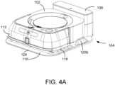
- FIG. 4A is a perspective view of the mobile cleaning robot 102 positioned on the base station 104.
- the mobile cleaning robot 102 is supported by the base station 104 in a charging position.
- wheels 310a and 310b of the mobile cleaning robot 102 are respectively positioned in wheel wells 122a and 122b of the platform 110.
- Electrical charging contacts 306a and 306b on the mobile cleaning robot 102 contact electrical charging contacts 116a and 116b of the base station, respectively.
- a minimum amount downward force is required to create contact sufficient for electrically connecting and charging the mobile cleaning robot 102. In some implementations, approximately one pound of downward force allows for charging.
- the downward force can be created through a variety of techniques, including gravity, magnetics, and mechanical springs alone or in combination with one another.
- gravity provides between approximately 0.1 and 1 pounds (e.g., 0.1 to 0.4 pounds, 0.4 to 0.7 pounds, 0.7 to 1.0 pounds) of downward force at the charging contacts 116a and 116b.
- the mobile cleaning robot 102 weighs between approximately 1 and 5 pounds (e.g., 1 to 2 pounds, 2 to 3 pounds, 3 to 5 pounds).
- the mobile cleaning robot 102 includes an internal storage reservoir (not shown) for holding fluid and a dispenser, such as a spray nozzle, for ejecting fluid onto a floor surface for cleaning. As cleaning fluid is applied to the floor surface, the weight of the mobile cleaning robot 102 decreases.
- the electrical charging contacts 116a and 116b of the base station accommodate this shifting range of robot weights.
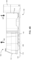
- FIG. 4B is a side view of the mobile cleaning robot 102 positioned on the base station 104.
- the cleaning pad 118 is supported by a plurality of raised surface features 402 of the platform 110.
- the support of the underside portion 304 (either the pad 118 or the debris pushing structure 308) of the mobile cleaning robot by the platform 110 helps to tilt the mobile cleaning robot 102 into the charging position.
- the forward portion 112 of the mobile cleaning robot 102 is pushed upward (as graphically represented by arrow 400) by a plurality of raised surface features 402 of the platform 110, which pivots the mobile cleaning robot 102 and causes the rear portion 114 of the robot to be pushed downward (as graphically represented by arrow 404).
- the mobile cleaning robot 102 may be placed on the base station 106 after the cleaning pad 118 has been removed. In such cases, a debris pushing structure 308 of the mobile cleaning robot 102 is exposed and is supported by the platform 110. Because the debris pushing structure 308 can be supported by the platform 110 in place of the pad 118, the mobile cleaning robot can charge regardless of whether the mobile cleaning robot 102 has a cleaning pad 118 attached or not.
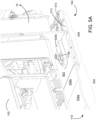
- FIG. 5A is a cutaway view of the mobile cleaning robot 102 positioned on the base station 104.
- the mobile cleaning robot 102 docks at the end of a cleaning mission.
- Electrical contact 116b has a domed shape and a contact surface 500 for contacting the electrical charging contact 306b of the mobile cleaning robot 102.
- the contact surface 500 of the electrical charging contact 116b is positioned above a horizontal surface 502 of the docking structure 106. As such, liquid that collects on the horizontal surface 502 is less likely to come in contact with the electrical charging contact 116b.
- the pad 118 may be made of a fibrous or cloth material that is configured to hold liquid. The outside of the pad 118 may be moist and, in some instances, liquid may drip from the pad 118.
- the horizontal surface 502 is co-planar with a rear portion 506a of a raised rear surface 506 of the platform 110. In some implementations, the horizontal surface 502 and raised rear surface 506 may not be co-planar with one another.
- the electrical charging contact 116b is surrounded by a finger-like projection 504b with sloped sides. Underneath the electrical charging contacts 116a and 116b, the docking structure includes a second fluid management area 508 to collect liquid.
- the second fluid management area 508 is a fluid collection tray that includes multiple compartments 510, 512 that collect liquid.
- the second fluid management area can hold fluid up to a volume of between approximately 0 and 100 mL (e.g., 0-25 mL, 25-50 mL, 50-75 mL, 75-100 mL). As liquid drips down from the horizontal surface, between a gap between the electrical charging contact 116b and the finger-like projections 504b, the liquid collects in the compartments 510, 512.
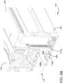
- FIG. 5B is another cutaway view of a mobile cleaning robot 102 positioned on the base station 104.
- An extension spring 512b is connected to the electrical charging contact 116b and provides at least a portion of a minimum downward force required for charging the mobile cleaning robot 102.
- the extension spring 512b provides between approximately 0.2 and 1 pounds of force (e.g., 0.2 to 0.5 pounds, 0.5 to 0.8 pounds, and 0.8 to 1.0 pounds).
- the charging contact 306b on the mobile cleaning robot 102 contacts the electrical charging contact 116b of the docking structure 106, the electrical charging contact 116b is displaced in a downward direction and the extension spring 512b is extended.
- the extension spring 512b When the electrical charging contact 116b is not in contact with the electrical charging contact 306b on the mobile cleaning robot 102, the extension spring 512b is in a less extended position, but is still in tension as the extension spring 512b pulls the electrical charging contact 116b up to a stop point.
- the extension spring 512b has a low spring constant such that a small increase or decrease in length of the spring from the movement of the electrical charging contact 116b results in a small change in contact force.
- FIG. 6A is a perspective view of a platform 110 of the base station 104 being connected to a docking structure 106 of the base station 104.
- the platform 110 has a forward portion 602 and a raised rear surface 506.
- the raised rear surface 506 has a front portion 506a and a rear portion 506b.
- Two wheel wells 122a and 122b are disposed in the front portion 506a of the raised rear surface 506. A close up of wheel well 122a is showed in an inset in FIG. 6A .
- Wheel well 122a has a curved surface with a maximum height H1 at the lowest point of the curve being between approximately 4 and 8 mm (e.g., 4-5 mm, 5-6 mm, 6-7 mm, 7-8 mm) below the front portion 506a of the raised rear surface 506.
- the depth of the wheel wells 122a and 122b is limited by the ground clearance of the mobile cleaning robot 102.
- the length L1 of the wheel well 122a is between approximately 20 and 30 mm (e.g., 20-25 mm, 25-30 mm) and is established by the depth and diameter of the wheel well curve.
- the curvature of the wheel well 122a is based on a circle that is between approximately 5 and 20 percent (e.g., 5-10 percent, 10-15 percent, 15-50 percent) larger than the wheel of the mobile cleaning robot 102.
- the wheel wells 122a and 122b have surface features 604a and 604b disposed on the curved surfaces of the wheel wells 122a and 122b, respectively.
- the surface features 604a and 604b may include raised tread that complement grooves on wheels 310a and 310b of the mobile cleaning robot to provide increased traction to the mobile robot when exiting the wheel wells 122a and 122b.
- the platform 110 also includes a first fluid management area 606 which is defined by a first sloping surface 608 and a second sloping surface 610.
- the first sloping surface 608 tapers from the forward portion 602 of the platform 110.
- the second sloping surface 610 tapers from the raised rear surface 506 of the platform.
- the fluid management area 606 slopes downward toward the raised rear surface 506 of the platform.
- the first sloping surface 608 has a sloping angle of between 5 and 15 degrees (e.g., 5-10 degrees, 10-15 degrees) and the second sloping surface 610 has a sloping angle of between 5 and 15 degrees (e.g., 5-10 degrees, 10-15 degrees).
- the first fluid management area 606 has a sloping angle of between 0.5 and 2 degrees (e.g., 0.5 to 1 degree, 1 to 1.5 degrees, 1.5 to 2 degrees).
- the fluid management area 606 is also defined by a right sloping surface 612 and a left sloping surface 614.
- the right sloping surface 612 tapers from the right outer portion 620b of the platform 110 and the left sloping surface 614 tapers from the left outer portion 620a of the platform 110.
- the right outer portion 620a and the left outer portion 620b ae continuous surfaces from the forward portion 602 of the platform and slope upward from the front edge 124 of the platform 110 toward the raised rear surface 506 at a sloping angle of between 0.5 and 2 degrees (e.g., 0.5 to 1 degree, 1 to 1.5 degrees, 1.5 to 2 degrees).
- the first fluid management area 606 includes a fluid collection area 616 proximate to the second sloping surface 610. Fluid will collect in the fluid collection area 616 as fluid flows down the sloping surfaces 608, 610, 612, and 614 and the surface of the first fluid management area 606.
- the fluid collection area 616 can hold fluid up to a volume of between approximately 0 and 100 mL (e.g., 0-25 mL, 25-50 mL, 50-75 mL, 75-100 mL).
- the first fluid management area 606 also includes a plurality of raised surface features 402.
- the raised surface features 402 are configured to support an underside portion of the mobile cleaning robot 102 when the mobile cleaning robot 102 is in a charging position on the base station 104.
- the raised surface features 402 have a domed shape and a height of between approximately 2 and 6 mm (e.g., 2-3 mm, 3-4 mm, 4-5 mm, 5-6 mm).
- the height of the raised surface features 402 is selected such that the raised surface features are tall enough to support and tilt the forward portion 112 of the mobile cleaning robot 102 into a charging position, but short enough that the mobile cleaning robot 102 can clear them with minimal ground clearance.
- the ground clearance of the mobile cleaning robot 102 (e.g., the shortest distance from the bottom surface of the robot to the ground) is between 5mm and 10mm (e.g., 5mm-10mm, 6mm-9mm, 7mm-8mm).
- At least some of the raised surface features 402 are located in the first fluid management area 606 forward to the fluid collection area 616.
- the raised surface features 402 are laid out in a pattern configured to allow the wheels of the mobile cleaning robot 102 to navigate between the raised surface features 402 in the pattern, without traversing over the raised surface features 402.
- the pattern of raised surface features 402 may help to guide the wheels 310a and 310b of the mobile cleaning robot toward the wheel wells 122a and 122b, respectively.
- the height of the raised surface features 402, the height H1 of the wheel wells 122a and 122b, and the height of the electrical charging contacts 116a and 116b are selected such that when the mobile cleaning robot 102 makes contact with the platform at these locations (wheel 310a in wheel well 122a, wheel 310b in wheel well 122b, electrical charging contact 306a touching electrical charging contact 116a, electrical charging contact 306b touching electrical charging contact 116b, and the pad or an underside portion of the mobile cleaning robot 102 being supported by the raised surface features 402), the mobile cleaning robot 102 is positioned such that the minimum downward force is produced at the electrical charging contacts 116a and 116b.
- the platform 110 also includes bumpers 120a and 120b.
- the bumpers 120a and 120b have sloping sides that may contact a body of the mobile cleaning robot 102 as it traverses the platform 110.
- the bumpers 120a and 120b have a height H2 of approximately between 18 and 50 mm (e.g., 18-30 mm, 30-40 mm, 40-50 mm) above the front portion 506a of the raised rear surface 506.
- the height of the bumpers 120a and 120b is configured such that, if the mobile cleaning robot 102 is off track and mounts one of the bumpers 120a and 120b as the mobile cleaning robot 102 attempts to dock on the base station 104, the electrical charging contacts 306a and 306b on the mobile cleaning robot 102 cannot make contact with the electrical charging contacts 116a and 116b on of the docking structure 106.
- each of the bumpers 120a and 120b has a rounded front shape and an angled inner edge to guide the mobile cleaning robot 102 into the charging position.
- the inside bottom edges of the bumpers 120a and 120b angle inward toward one another such that there is less space between the inside bottom edges of the bumpers 120a and 120b as the bumpers 120a and 120b extend backward across the raised rear surface 506.
- the bumpers 120a and 120b are positioned on the raised rear surface 506 of the platform 110 such that the bumpers 120a and 120b do not extend forward past the wheel wells 122a and 122b.
- the bumpers 120a and 120b may extend forward of the wheel wells 122a and 122b, however, the bumpers 120a and 120b should not extend forward so much that they interfere with the mobility of the robot. In some implementations, the bumpers 120a and 120b may extend further backward and inward toward the docking structure 106 such that the bumpers 120a and 120b form a U-shape along the back of the base station 104.
- FIG. 6B is a side view of the base station 104.
- the left and right outer surfaces 620a and 620b of the platform 110 generally slope upward from the front edge 124 of the platform 110 to the forward portion 506a of the raised rear surface 506. This general upward slope of the outer surfaces 620a and 620b is the opposite of the downward slope of the first fluid management area 606 toward the raised rear surface 506.
- the raised surface features 402 have a height taller than the left and right outer surfaces 620a and 620b.
- the bumpers 120a and 120b are positioned on the raised rear surface 506 and have a height H2 of approximately between 18 and 50 mm (e.g., 18-30 mm, 30-40 mm, 40-50 mm) above the front portion 506a of the raised rear surface 506.
- the charging contacts 116a and 116b are positioned at a height H3 above the rear portion 506b of the raised rear surface 506 which is between approximately 4 and 8 mm (e.g., 4 to 6 mm, 6 to 8 mm). Height H3 is established by the distance from a floor surface to the contacts in the robot.
- a wire management feature 621 is located on the back of the docking station 106 for keeping a power cord for the base station tidy.
- FIG. 6C is a perspective view of the platform 110 of the base station 104 being separated from the docking structure 160 of the base station 104.
- the platform 110 and the docking structure 106 are connectable via a locking feature.
- the locking feature includes two connectors 622a and 622b that fit into two sockets 624a and 624b, respectively.
- the connector 622a is T-shaped and the corresponding socket 624a has a notch 626a to fit a stem of the T-shaped connector 622a.
- the platform 110 and the docking structure 106 must be lifted vertically relative to one another in order to disconnect the connectors 622a and 622b from their corresponding sockets 624a and 624b. As such, the platform 110 cannot be slid horizontally to separate the platform 110 from the docking structure 106. This feature is important because the robot, as it moves across the platform 110, cannot substantially move or unseat the platform 110 from the docking structure 106.
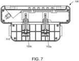
- FIG. 7 is a bottom view of the docking structure 106 of the base station 104.
- the docking structure has gaps 702a and 702b underneath the electrical charging contacts 116a and 116b to allow fluid to drain should any fluid fall between the electrical charging contacts 116a and 116b and the horizontal surface 502.
- the compartments 510 of the second fluid management area 508 are positioned underneath the horizontal surface 502 to catch fluid and protect the underlying floor surface.
- FIG. 8 is a flowchart 800 of operations for docking the mobile cleaning robot on the base station.
- the method includes sensing (802) a presence of a base station with the mobile cleaning robot, the mobile cleaning robot comprising a wet cleaning pad.
- the method also includes approaching (804) the base station with the mobile cleaning robot and upon reaching a threshold distance from the base station, turning (806) the mobile cleaning robot such that a rear of the mobile cleaning robot is presented to the base station.
- the method also includes reversing (808) the mobile cleaning robot onto the base station and contacting (810) at least two charging contacts on the mobile cleaning robot with at least two corresponding electrical charging contacts on the base station, the electrical charging contacts on the base station each having a contact surface being positioned above a horizontal surface of the base station.
- Operations associated with implementing all or part of the navigation techniques described herein can be performed by one or more programmable processors executing one or more computer programs to perform the functions described herein.
- the robot's controller may include processors programmed with computer programs for executing functions such as transmitting signals, computing a pose of the robot, or interpreting signals.
- a computer program can be written in any form of programming language, including compiled or interpreted languages, and it can be deployed in any form, including as a stand-alone program or as a module, component, subroutine, or other unit suitable for use in a computing environment.
Landscapes
- Engineering & Computer Science (AREA)
- Mechanical Engineering (AREA)
- Robotics (AREA)
- General Physics & Mathematics (AREA)
- Aviation & Aerospace Engineering (AREA)
- Radar, Positioning & Navigation (AREA)
- Remote Sensing (AREA)
- Physics & Mathematics (AREA)
- Automation & Control Theory (AREA)
- Transportation (AREA)
- Power Engineering (AREA)
- Electric Vacuum Cleaner (AREA)
- Control Of Position, Course, Altitude, Or Attitude Of Moving Bodies (AREA)
- Manipulator (AREA)
Description
- This specification relates generally to robotic cleaning systems, and more particularly to systems and techniques for docking mobile cleaning robots.
- Mobile cleaning robots can autonomously perform cleaning tasks within an environment, e.g., a home. Many kinds of mobile cleaning robots are autonomous to some degree and in different ways. For example, an autonomous cleaning robot may be designed to automatically dock with a base station for the purpose of charging.
-
US 2014/0100693 A1 ,US 2016/0070268 A1 andKR 100669888 B - The present invention relates to a base station for receiving a mobile cleaning robot as set out in claim 1 and a system including a base station and a mobile cleaning robot as set out in claim 15. The base station includes a docking structure. The docking structure includes a horizontal surface and at least two electrical charging contacts, each of the electrical charging contacts having a contact surface positioned above the horizontal surface. The base station also includes a platform that is connectable to the docking structure. The platform includes a raised rear surface having a front portion and a rear portion, the rear portion configured to be substantially co-planar with the horizontal surface of the docking structure when the platform is connected to the docking structure, two wheel wells located in the front portion of the raised rear surface of the platform, each wheel well having a recessed surface being configured to receive a wheel of the robot, the recessed surface of each wheel well having raised tread to complement grooves of the respective wheels of the robot, and a plurality of raised surface features forward of the raised rear surface configured to support an underside portion of the mobile cleaning robot.
- In some implementations, the underside portion of the mobile cleaning robot includes a cleaning pad configured to hold liquid.
- In some implementations, the underside portion of the mobile cleaning robot includes a cleaning pad holder. In some implementations, the underside portion of the mobile cleaning robot includes a debris pushing structure.
- In some implementations, the plurality of raised surface features causes the received mobile cleaning robot to tilt into a charging position. In some cases, when the mobile cleaning robot is in the charging position, one of the at least two electrical charging contacts experiences at least one pound of downward force, wherein the mobile cleaning robot has a weight of between 2 and 3 pounds.
- In some implementations, each of the at least two electrical contacts is connected to an extension spring.
- In some implementations, the contact surfaces of each of the at least two electrical charging contacts have a domed geometry.
- In some implementations, the platform further includes at least two bumpers on the raised rear surface, the bumpers being located to guide the robot into a charging position. In some cases, the bumpers have a height between 18 and 50 mm. In some cases, the bumpers include sloping side walls for directing the wheels of the mobile cleaning robot into the wheel wells. In some implementations, the raised surface features are arranged in a pattern to allow wheels of the mobile cleaning robot to traverse a portion of the platform.
- In some implementations, the wheel wells have a depth of between 4 and 8 mm. In some implementations, the at least two electrical charging contacts are positioned such that a highest point of each contact surface is between 4 and 8 mm above the horizontal surface.
- In some implementations, the docking structure and the platform are connectable via a locking feature.
- In some implementations, a front edge of the platform has a height less than a height of the raised rear surface of the platform.
- The base station for receiving a mobile cleaning robot can include a first fluid management area being defined by a first sloping surface and a second sloping surface of the platform, the first sloping surface tapering from a forward portion of the platform, and the second sloping surface tapering from the raised rear surface.
- In some implementations, the first fluid management area includes a fluid collection area proximate to the second sloping surface.
- In some implementations, the at least two electrical charging contacts are positioned such that a highest point of each contact surface is between 4 and 8 mm above the horizontal surface.
- In some implementations, the platform includes a plurality of raised surface features configured to support an underside portion of the mobile cleaning robot. In some cases, at least some of the plurality of raised surface features are located in the first fluid management area and forward to the fluid collection area.
- In some implementations, the docking structure comprises a second fluid management area located below the electrical charging contacts, the second fluid management area comprising a fluid collection tray. In some cases, the fluid collection tray comprises a plurality of fluid collecting compartments. In some cases, the fluid collection tray holds between 0 and 100 mL of fluid.
- In some implementations, the first fluid management area is further defined by a left sloping surface and a right sloping surface.
- In some implementations, the first sloping surface has a sloping angle of between 5 and 15 degrees and wherein the second sloping surface has a sloping angle of between 5 and 15 degrees.
- In some implementations, the first fluid management area is sloped downward toward the second sloping surface at an angle of between 0.5 and 2 degrees.
- In some implementations, the first fluid management area holds between 0 and 100 mL of fluid. In some implementations, the first sloping surface is inbound from a front edge of the platform.
- Advantages of the foregoing may include, but are not limited to, those described below and herein elsewhere. With a docking station configured to support an underside of a mobile cleaning robot, adequate force can be applied to electrical charging contacts on the docking station to allow for charging. With a docking station configured to manage fluid, fluid that accumulates in a wet cleaning pad on a mobile cleaning robot drains from the robot and collects in specific areas on the docking station such that charging is not interrupted and the fluid can be easily disposed of. With a mobile robot able to enter the docking station backwards, the electrical charging contacts of the docking station do not come into contact with a wet cleaning pad of the mobile robot.
- The details of one or more implementations of the subject matter described in this specification are set forth in the accompanying drawings and the description below. Other potential features, aspects, and advantages will become apparent from the description, the drawings, and the claims.
-
-
FIG. 1 is a view of a mobile cleaning robot approaching an exemplary base station. -
FIG. 2 is a view of the mobile cleaning robot backing into the base station ofFIG. 1 . -
FIG. 3 is a bottom view of the mobile cleaning robot ofFIG. 1 . -
FIG. 4A is a perspective view of the mobile cleaning robot positioned on the base station ofFIG. 1 . -
FIG. 4B is a side view of the mobile cleaning robot positioned on the base station ofFIG. 1 . -
FIG. 5A is a cutaway view of the mobile cleaning robot positioned on the base station ofFIG. 1 . -
FIG. 5B is another cutaway view of a mobile cleaning robot positioned on the base station ofFIG. 1 . -
FIG. 6A is a perspective view of a platform of the base station being connected to a docking structure of the base station ofFIG. 1 . -
FIG. 6B is a side view of the base station ofFIG. 1 . -
FIG. 6C is a perspective view of the platform of the base station being separated from the docking structure of the base station ofFIG. 1 . -
FIG. 7 is a bottom view of the docking structure of the base station ofFIG. 1 . -
FIG. 8 is a flowchart of operations for docking the mobile cleaning robot on the base station ofFIG. 1 . - The present specification relates to systems and techniques for docking and charging a mobile cleaning robot that employs a wet cleaning pad. To avoid contacting the wet cleaning pad of the mobile cleaning robot with electrical charging contacts on a base station, the mobile cleaning robot enters the dock driving in a backward direction. Additionally, the base station provides electrical charging contacts for charging the mobile cleaning robot which must be contacted with a minimum amount of force for charging to occur. The base station provides support to portions of the mobile cleaning robot to position the mobile cleaning robot in a charging position that applies at least the minimum required force. Additionally, the base station manages fluid that may drip off of the mobile cleaning robot such that it does not spill off of the base station and may be easily discarded.
- Referring to
FIG. 1 , amobile cleaning robot 102 approaches abase station 104 for docking (e.g., to charge one or more batteries contained in the robot). Themobile cleaning robot 102 is configured to communicate with adocking structure 106 of thebase station 104. In some cases, themobile cleaning robot 102 may include asensor 108 on aforward portion 112 of themobile cleaning robot 102 for communicating with thedocking structure 106. Thedocking structure 106 may include a wireless communication system configured to transmit and receive data with a communications module (not shown as the communications module is inside of a bumper of the mobile cleaning robot 102) and thesensor 108 on themobile cleaning robot 102. The wireless communication system of thedocking station 106 includes homing and alignment emitters operable to emit left and right homing signals (e.g., optical, infrared (IR), radiofrequency (RF), etc. signals) detectable by thesensor 108 of themobile cleaning robot 102. - In some examples, the
mobile cleaning robot 102 may search for and detect the homing signals. Once the homing signals are detected, themobile cleaning robot 102 initiates an aligning and docking procedure to dock itself on aplatform 110 of thebase station 104. The aligning and docking procedure allows themobile cleaning robot 102 to dock on thebase station 104 without running acleaning pad 118 of themobile cleaning robot 102 overelectrical charging contacts base station 104. First, themobile cleaning robot 102 aligns itself with thebase station 104 using the homing signals emitted by thebase station 104 and presents aforward portion 112 of themobile cleaning robot 102 to thebase station 104. Themobile cleaning robot 102 then turns approximately 180° (as graphically represented by arrow 117) to present arear portion 114 of themobile cleaning robot 102 to thebase station 104. In some implementations, themobile cleaning robot 102 uses wheel tachometers, odometers, etc. to determine the distance travelled by the wheels and computes (e.g., using an internal controller), the position of therear portion 114 of themobile cleaning robot 102 relative to thebase station 104. In some implementations, themobile cleaning robot 102 uses a camera and feature identifier (e.g., software executed on board the robot) to identify features of the robot's environment to orient themobile cleaning robot 102 relative to thebase station 104. In some implementations, themobile cleaning robot 102 uses a communications module on arear portion 114 of the robot to align with the communications system of thedocking structure 106. A communications module on therear portion 114, in embodiments, includes sensors such as those described above in embodiments having sensors on theforward portion 112 of themobile cleaning robot 102. -
FIG. 2 is a view of themobile cleaning robot 102 backing into thebase station 104. Upon determining that themobile cleaning robot 102 is in a correct position for backing into thebase station 104, themobile cleaning robot 102 begins driving backwards onto the platform 110 (as graphically represented by arrow 200). In some implementations where themobile cleaning robot 102 includes a communications module on arear portion 114 of themobile cleaning robot 102, thebumpers mobile cleaning robot 102 is guided into a charging position bybumpers bumpers mobile cleaning robot 102 as it moves across theplatform 110. In the charging position, wheels of themobile cleaning robot 102 are respectively positioned inwheel wells platform 110 and charging contacts (hidden from view in the figure) on themobile cleaning robot 102 contactelectrical charging contacts mobile cleaning robot 102 may drive forward and exit thebase station 104. - Additionally, the
platform 110 has afront edge 124 with a height that is configured to allow arear edge 126 of thecleaning pad 118 to slide over thefront edge 124 of theplatform 110 without getting caught or folded as themobile cleaning robot 102 traverses theplatform 110. The height of thefront edge 124 of theplatform 110 is approximately between 0 mm and 4.5 mm (e.g., 0-2 mm, 2-3 mm, 3-4.5 mm, etc.). This height accommodates a robot with a low ground clearance between the bottom of the robot and the floor, for example a ground clearance of less than 10mm (e.g. 1mm, 2mm, 3mm, 4mm, 5mm, 6mm, 7mm, 8mm, 9mm). In embodiments, the ground clearance of the mobile cleaning robot 102 (e.g., the shortest distance from the bottom surface of the robot to the ground) is between 5mm and 10mm (e.g., 5mm-10mm, 6mm-9mm, 7mm-8mm). In embodiments, the ground clearance of themobile cleaning robot 102 is 6mm to the bottom of the robot and 7.5mm between the contacts and the floor surface. -
FIG. 3 is a bottom view of themobile cleaning robot 102 and illustrates thecleaning pad 118 being carried on anunderside portion 304 of themobile cleaning robot 102. Thecleaning pad 118 is configured to hold liquid and to be used during a mopping cleaning mission. In some implementations, thecleaning pad 118 may be a dry cleaning pad that is configured to be used during a sweeping or dusting cleaning mission. Themobile cleaning robot 102 also includescliff sensors 302a-d for providing data to a controller of themobile cleaning robot 102 for obstacle detection and navigation of themobile cleaning robot 102 during a cleaning mission to prevent themobile cleaning robot 102 from attempting to traverse a significant change in flooring height. - The
mobile cleaning robot 102 also includeselectrical charging contacts electrical charging contacts electrical charging contacts electrical charging contacts base station 106 after the user has removed thecleaning pad 118. In such cases, adebris pushing structure 308 of themobile cleaning robot 102 is exposed and is supported by theplatform 110. Themobile cleaning robot 102 includes twowheels mobile cleaning robot 102. Thewheels mobile cleaning robot 102 as it moves across a floor surface, for example, a wet floor surface or a smooth, polished floor surface. -
FIG. 4A is a perspective view of themobile cleaning robot 102 positioned on thebase station 104. After theplatform 110 is traversed during a docking procedure, themobile cleaning robot 102 is supported by thebase station 104 in a charging position. In the charging position,wheels mobile cleaning robot 102 are respectively positioned inwheel wells platform 110.Electrical charging contacts mobile cleaning robot 102 contactelectrical charging contacts mobile cleaning robot 102. In some implementations, approximately one pound of downward force allows for charging. The downward force can be created through a variety of techniques, including gravity, magnetics, and mechanical springs alone or in combination with one another. In one implementation, gravity provides between approximately 0.1 and 1 pounds (e.g., 0.1 to 0.4 pounds, 0.4 to 0.7 pounds, 0.7 to 1.0 pounds) of downward force at the chargingcontacts mobile cleaning robot 102 weighs between approximately 1 and 5 pounds (e.g., 1 to 2 pounds, 2 to 3 pounds, 3 to 5 pounds). - In implementations, the
mobile cleaning robot 102 includes an internal storage reservoir (not shown) for holding fluid and a dispenser, such as a spray nozzle, for ejecting fluid onto a floor surface for cleaning. As cleaning fluid is applied to the floor surface, the weight of themobile cleaning robot 102 decreases. Theelectrical charging contacts -
FIG. 4B is a side view of themobile cleaning robot 102 positioned on thebase station 104. Thecleaning pad 118 is supported by a plurality of raised surface features 402 of theplatform 110. The support of the underside portion 304 (either thepad 118 or the debris pushing structure 308) of the mobile cleaning robot by theplatform 110 helps to tilt themobile cleaning robot 102 into the charging position. Theforward portion 112 of themobile cleaning robot 102 is pushed upward (as graphically represented by arrow 400) by a plurality of raised surface features 402 of theplatform 110, which pivots themobile cleaning robot 102 and causes therear portion 114 of the robot to be pushed downward (as graphically represented by arrow 404). Themobile cleaning robot 102 may be placed on thebase station 106 after thecleaning pad 118 has been removed. In such cases, adebris pushing structure 308 of themobile cleaning robot 102 is exposed and is supported by theplatform 110. Because thedebris pushing structure 308 can be supported by theplatform 110 in place of thepad 118, the mobile cleaning robot can charge regardless of whether themobile cleaning robot 102 has acleaning pad 118 attached or not. -
FIG. 5A is a cutaway view of themobile cleaning robot 102 positioned on thebase station 104. In some implementations, themobile cleaning robot 102 docks at the end of a cleaning mission.Electrical contact 116b has a domed shape and acontact surface 500 for contacting theelectrical charging contact 306b of themobile cleaning robot 102. Thecontact surface 500 of theelectrical charging contact 116b is positioned above ahorizontal surface 502 of thedocking structure 106. As such, liquid that collects on thehorizontal surface 502 is less likely to come in contact with theelectrical charging contact 116b. Thepad 118 may be made of a fibrous or cloth material that is configured to hold liquid. The outside of thepad 118 may be moist and, in some instances, liquid may drip from thepad 118. - The
horizontal surface 502 is co-planar with arear portion 506a of a raisedrear surface 506 of theplatform 110. In some implementations, thehorizontal surface 502 and raisedrear surface 506 may not be co-planar with one another. Theelectrical charging contact 116b is surrounded by a finger-like projection 504b with sloped sides. Underneath theelectrical charging contacts fluid management area 508 to collect liquid. The secondfluid management area 508 is a fluid collection tray that includesmultiple compartments electrical charging contact 116b and the finger-like projections 504b, the liquid collects in thecompartments -
FIG. 5B is another cutaway view of amobile cleaning robot 102 positioned on thebase station 104. Anextension spring 512b is connected to theelectrical charging contact 116b and provides at least a portion of a minimum downward force required for charging themobile cleaning robot 102. In some implementations, theextension spring 512b provides between approximately 0.2 and 1 pounds of force (e.g., 0.2 to 0.5 pounds, 0.5 to 0.8 pounds, and 0.8 to 1.0 pounds). As the chargingcontact 306b on the mobile cleaning robot 102 (not shown in the figure) contacts theelectrical charging contact 116b of thedocking structure 106, theelectrical charging contact 116b is displaced in a downward direction and theextension spring 512b is extended. When theelectrical charging contact 116b is not in contact with theelectrical charging contact 306b on themobile cleaning robot 102, theextension spring 512b is in a less extended position, but is still in tension as theextension spring 512b pulls theelectrical charging contact 116b up to a stop point. Theextension spring 512b has a low spring constant such that a small increase or decrease in length of the spring from the movement of theelectrical charging contact 116b results in a small change in contact force. -
FIG. 6A is a perspective view of aplatform 110 of thebase station 104 being connected to adocking structure 106 of thebase station 104. Theplatform 110 has aforward portion 602 and a raisedrear surface 506. The raisedrear surface 506 has afront portion 506a and arear portion 506b. Twowheel wells front portion 506a of the raisedrear surface 506. A close up ofwheel well 122a is showed in an inset inFIG. 6A .Wheel well 122a has a curved surface with a maximum height H1 at the lowest point of the curve being between approximately 4 and 8 mm (e.g., 4-5 mm, 5-6 mm, 6-7 mm, 7-8 mm) below thefront portion 506a of the raisedrear surface 506. The depth of thewheel wells mobile cleaning robot 102. The length L1 of thewheel well 122a is between approximately 20 and 30 mm (e.g., 20-25 mm, 25-30 mm) and is established by the depth and diameter of the wheel well curve. The curvature of thewheel well 122a is based on a circle that is between approximately 5 and 20 percent (e.g., 5-10 percent, 10-15 percent, 15-50 percent) larger than the wheel of themobile cleaning robot 102. Thewheel wells surface features wheel wells wheels wheel wells - The
platform 110 also includes a first fluid management area 606 which is defined by a firstsloping surface 608 and a secondsloping surface 610. The firstsloping surface 608 tapers from theforward portion 602 of theplatform 110. The secondsloping surface 610 tapers from the raisedrear surface 506 of the platform. The fluid management area 606 slopes downward toward the raisedrear surface 506 of the platform. The firstsloping surface 608 has a sloping angle of between 5 and 15 degrees (e.g., 5-10 degrees, 10-15 degrees) and the secondsloping surface 610 has a sloping angle of between 5 and 15 degrees (e.g., 5-10 degrees, 10-15 degrees). The first fluid management area 606 has a sloping angle of between 0.5 and 2 degrees (e.g., 0.5 to 1 degree, 1 to 1.5 degrees, 1.5 to 2 degrees). - The fluid management area 606 is also defined by a right
sloping surface 612 and a leftsloping surface 614. The rightsloping surface 612 tapers from the rightouter portion 620b of theplatform 110 and the left slopingsurface 614 tapers from the leftouter portion 620a of theplatform 110. The rightouter portion 620a and the leftouter portion 620b ae continuous surfaces from theforward portion 602 of the platform and slope upward from thefront edge 124 of theplatform 110 toward the raisedrear surface 506 at a sloping angle of between 0.5 and 2 degrees (e.g., 0.5 to 1 degree, 1 to 1.5 degrees, 1.5 to 2 degrees). The first fluid management area 606 includes afluid collection area 616 proximate to the secondsloping surface 610. Fluid will collect in thefluid collection area 616 as fluid flows down the slopingsurfaces fluid collection area 616 can hold fluid up to a volume of between approximately 0 and 100 mL (e.g., 0-25 mL, 25-50 mL, 50-75 mL, 75-100 mL). - The first fluid management area 606 also includes a plurality of raised surface features 402. The raised surface features 402 are configured to support an underside portion of the
mobile cleaning robot 102 when themobile cleaning robot 102 is in a charging position on thebase station 104. The raised surface features 402 have a domed shape and a height of between approximately 2 and 6 mm (e.g., 2-3 mm, 3-4 mm, 4-5 mm, 5-6 mm). The height of the raised surface features 402 is selected such that the raised surface features are tall enough to support and tilt theforward portion 112 of themobile cleaning robot 102 into a charging position, but short enough that themobile cleaning robot 102 can clear them with minimal ground clearance. In embodiments, the ground clearance of the mobile cleaning robot 102 (e.g., the shortest distance from the bottom surface of the robot to the ground) is between 5mm and 10mm (e.g., 5mm-10mm, 6mm-9mm, 7mm-8mm). At least some of the raised surface features 402 are located in the first fluid management area 606 forward to thefluid collection area 616. The raised surface features 402 are laid out in a pattern configured to allow the wheels of themobile cleaning robot 102 to navigate between the raised surface features 402 in the pattern, without traversing over the raised surface features 402. The pattern of raised surface features 402 may help to guide thewheels wheel wells - The height of the raised surface features 402, the height H1 of the
wheel wells electrical charging contacts mobile cleaning robot 102 makes contact with the platform at these locations (wheel 310a inwheel well 122a,wheel 310b inwheel well 122b,electrical charging contact 306a touchingelectrical charging contact 116a,electrical charging contact 306b touchingelectrical charging contact 116b, and the pad or an underside portion of themobile cleaning robot 102 being supported by the raised surface features 402), themobile cleaning robot 102 is positioned such that the minimum downward force is produced at theelectrical charging contacts - The
platform 110 also includesbumpers bumpers mobile cleaning robot 102 as it traverses theplatform 110. Thebumpers front portion 506a of the raisedrear surface 506. The height of thebumpers mobile cleaning robot 102 is off track and mounts one of thebumpers mobile cleaning robot 102 attempts to dock on thebase station 104, theelectrical charging contacts mobile cleaning robot 102 cannot make contact with theelectrical charging contacts docking structure 106. - The footprint of each of the
bumpers mobile cleaning robot 102 into the charging position. When looking down at theplatform 110 from above, the inside bottom edges of thebumpers bumpers bumpers rear surface 506. Thebumpers rear surface 506 of theplatform 110 such that thebumpers wheel wells bumpers wheel wells bumpers bumpers docking structure 106 such that thebumpers base station 104. -
FIG. 6B is a side view of thebase station 104. The left and rightouter surfaces platform 110 generally slope upward from thefront edge 124 of theplatform 110 to theforward portion 506a of the raisedrear surface 506. This general upward slope of theouter surfaces rear surface 506. The raised surface features 402 have a height taller than the left and rightouter surfaces bumpers rear surface 506 and have a height H2 of approximately between 18 and 50 mm (e.g., 18-30 mm, 30-40 mm, 40-50 mm) above thefront portion 506a of the raisedrear surface 506. The chargingcontacts rear portion 506b of the raisedrear surface 506 which is between approximately 4 and 8 mm (e.g., 4 to 6 mm, 6 to 8 mm). Height H3 is established by the distance from a floor surface to the contacts in the robot. Awire management feature 621 is located on the back of thedocking station 106 for keeping a power cord for the base station tidy. -
FIG. 6C is a perspective view of theplatform 110 of thebase station 104 being separated from the docking structure 160 of thebase station 104. Theplatform 110 and thedocking structure 106 are connectable via a locking feature. The locking feature includes twoconnectors sockets connector 622a is T-shaped and the correspondingsocket 624a has anotch 626a to fit a stem of the T-shapedconnector 622a. - The
platform 110 and thedocking structure 106 must be lifted vertically relative to one another in order to disconnect theconnectors corresponding sockets platform 110 cannot be slid horizontally to separate theplatform 110 from thedocking structure 106. This feature is important because the robot, as it moves across theplatform 110, cannot substantially move or unseat theplatform 110 from thedocking structure 106. Because proper contact for charging themobile cleaning robot 102 is dependent on proper positioning of themobile cleaning robot 102 on the platform 110 (e.g., support by the raised surface features 402, thewheel wells electrical charging contacts mobile cleaning robot 102 to charge on thebase station 104. The vertical detachment geometry of theplatform 110 from thedocking structure 106 also allows for a user to pick up theplatform 110 with minimal horizontal sloshing of fluid that may have collected on theplatform 110. The separability of theplatform 110 and thedocking structure 106 allows for washing theplatform 110 independently from thedocking structure 106. -
FIG. 7 is a bottom view of thedocking structure 106 of thebase station 104. The docking structure hasgaps electrical charging contacts electrical charging contacts horizontal surface 502. Thecompartments 510 of the secondfluid management area 508 are positioned underneath thehorizontal surface 502 to catch fluid and protect the underlying floor surface. -
FIG. 8 is aflowchart 800 of operations for docking the mobile cleaning robot on the base station. The method includes sensing (802) a presence of a base station with the mobile cleaning robot, the mobile cleaning robot comprising a wet cleaning pad. The method also includes approaching (804) the base station with the mobile cleaning robot and upon reaching a threshold distance from the base station, turning (806) the mobile cleaning robot such that a rear of the mobile cleaning robot is presented to the base station. The method also includes reversing (808) the mobile cleaning robot onto the base station and contacting (810) at least two charging contacts on the mobile cleaning robot with at least two corresponding electrical charging contacts on the base station, the electrical charging contacts on the base station each having a contact surface being positioned above a horizontal surface of the base station. - Operations associated with implementing all or part of the navigation techniques described herein can be performed by one or more programmable processors executing one or more computer programs to perform the functions described herein. For example, the robot's controller may include processors programmed with computer programs for executing functions such as transmitting signals, computing a pose of the robot, or interpreting signals. A computer program can be written in any form of programming language, including compiled or interpreted languages, and it can be deployed in any form, including as a stand-alone program or as a module, component, subroutine, or other unit suitable for use in a computing environment.
- Elements of different implementations described herein may be combined to form other implementations not specifically set forth above. Elements may be left out of the structures described herein without adversely affecting their operation. Furthermore, various separate elements may be combined into one or more individual elements to perform the functions described herein.
Claims (15)
- A base station (104) for receiving a mobile cleaning robot (102) comprising:a docking structure (106) comprising:a horizontal surface (502); andat least two electrical charging contacts (116a; 116b), each of the electrical charging contacts having a contact surface (500) positioned above the horizontal surface; characterized in that the base station (104) further comprisesa platform (110) that is connectable to the docking structure, the platform comprising:a raised rear surface (506) having a front portion (506a) and a rear portion (506b), the rear portion configured to be substantially co-planar with the horizontal surface of the docking structure when the platform is connected to the docking structure;two wheel wells (122a, 122b) located in the front portion of the raised rear surface of the platform, each wheel well having a recessed surface being configured to receive a wheel of the robot, the recessed surface of each wheel well having raised tread to complement grooves of the respective wheels of the robot; anda plurality of raised surface features (402) forward of the raised rear surface configured to support an underside portion of the mobile cleaning robot.
- The base station of claim 1, wherein the underside portion of the mobile cleaning robot includes a cleaning pad (118) configured to hold liquid.
- The base station of claim 1, wherein the underside portion of the mobile cleaning robot includes a cleaning pad holder.
- The base station of claim 1, wherein the plurality of raised surface features causes the received mobile cleaning robot to tilt into a charging position.
- The base station of claim 4, wherein when the mobile cleaning robot is in the charging position, one of the at least two electrical charging contacts experiences at least one pound of downward force, wherein the mobile cleaning robot has a weight of between 2 and 3 pounds.
- The base station of claim 1, wherein each of the at least two electrical contacts is connected to an extension spring (512b).
- The base station of claim 1, further comprising at least two bumpers (120a, 120b) on the raised rear surface, the bumpers being located to guide the robot into a charging position, optionally wherein the bumpers include sloping side walls for directing the wheels of the mobile cleaning robot into the wheel wells.
- The base station of claim 1, wherein the raised surface features are arranged in a pattern to allow wheels of the mobile cleaning robot to traverse a portion of the platform.
- The base station of claim 1, wherein a front edge of the platform has a height less than a height of the raised rear surface of the platform.
- The base station for receiving a mobile cleaning robot of any one of the preceding claims 1 to 9, the platform further comprising:
a first fluid management area (606) being defined by a first sloping surface (608) and a second sloping surface (610) of the platform, the first sloping surface tapering from a forward portion of the platform, and the second sloping surface tapering from the raised rear surface. - The base station of claim 10, wherein the first fluid management area includes a fluid collection area (616) proximate to the second sloping surface.
- The base station of claim 10, wherein the docking structure comprises a second fluid management area (508) located below the electrical charging contacts, the second fluid management area comprising a fluid collection tray.
- The base station of claim 10, wherein the first sloping surface has a sloping angle of between 5 and 15 degrees and wherein the second sloping surface has a sloping angle of between 5 and 15 degrees.
- The base station of claim 10, wherein the first sloping surface is inbound from a front edge (124) of the platform.
- A system including:the base station (104) of any one of claims 1 to 14; anda mobile cleaning robot (102) configured to sit on the base station.
Applications Claiming Priority (2)
| Application Number | Priority Date | Filing Date | Title |
|---|---|---|---|
| US15/693,349 US10383499B2 (en) | 2017-08-31 | 2017-08-31 | Wet robot docking station |
| PCT/US2018/049110 WO2019046729A1 (en) | 2017-08-31 | 2018-08-31 | Wet robot docking station |
Publications (3)
| Publication Number | Publication Date |
|---|---|
| EP3676932A1 EP3676932A1 (en) | 2020-07-08 |
| EP3676932A4 EP3676932A4 (en) | 2021-05-26 |
| EP3676932B1 true EP3676932B1 (en) | 2023-12-13 |
Family
ID=65436359
Family Applications (1)
| Application Number | Title | Priority Date | Filing Date |
|---|---|---|---|
| EP18852133.0A Active EP3676932B1 (en) | 2017-08-31 | 2018-08-31 | Wet robot docking station |
Country Status (4)
| Country | Link |
|---|---|
| US (2) | US10383499B2 (en) |
| EP (1) | EP3676932B1 (en) |
| CN (6) | CN209360595U (en) |
| WO (1) | WO2019046729A1 (en) |
Families Citing this family (59)
| Publication number | Priority date | Publication date | Assignee | Title |
|---|---|---|---|---|
| US10383499B2 (en) | 2017-08-31 | 2019-08-20 | Irobot Corporation | Wet robot docking station |
| CN208973678U (en) * | 2017-09-19 | 2019-06-14 | 北京石头世纪科技股份有限公司 | Dampproofing pad and clean system of intelligence |
| DE102017126414A1 (en) * | 2017-11-10 | 2019-05-16 | Vorwerk & Co. Interholding Gmbh | Moist cleaning device for cleaning a surface |
| USD901797S1 (en) * | 2018-01-12 | 2020-11-10 | Ecovacs Robotics Co., Ltd. | Corner of a robotic cleaner |
| KR102090649B1 (en) * | 2018-02-28 | 2020-03-18 | 엘지전자 주식회사 | Moving robot and Moving robot system |
| JP2021526446A (en) * | 2018-06-08 | 2021-10-07 | ポジテック パワー ツールズ(スーチョウ)カンパニー,リミティド | Cleaning robot and its control method, cleaning robot system |
| KR102137164B1 (en) * | 2018-06-15 | 2020-07-24 | 엘지전자 주식회사 | Guidance robot |
| EP3838096B1 (en) * | 2018-06-22 | 2021-11-03 | Bissell Inc. | Surface cleaning apparatus |
| KR102292263B1 (en) * | 2018-08-03 | 2021-08-24 | 엘지전자 주식회사 | Moving robot, system of moving robot and method for moving to charging station of moving robot |
| USD906236S1 (en) * | 2018-08-03 | 2020-12-29 | Techtronic Cordless Gp | Docking station for mowers |
| USD907676S1 (en) * | 2018-10-30 | 2021-01-12 | Quantum Spatial, Inc. | Docking station for a robotic platform |
| USD938115S1 (en) | 2018-11-30 | 2021-12-07 | Irobot Corporation | Autonomous floor cleaning robot |
| CN113165162A (en) * | 2018-12-03 | 2021-07-23 | Groove X 株式会社 | Charging station for robot |
| USD909440S1 (en) * | 2019-01-28 | 2021-02-02 | Tata Consultancy Services Limited | Cobot mounting platform |
| JP2020162397A (en) * | 2019-03-28 | 2020-10-01 | 本田技研工業株式会社 | Autonomous driving machine and charging station |
| CA3135276A1 (en) | 2019-04-17 | 2020-10-22 | Bard Access Systems, Inc. | Catheter securement device including extended anchor pad and release liner clasping features |
| US11564547B2 (en) | 2019-04-30 | 2023-01-31 | Irobot Corporation | Cleaning pad for an autonomous cleaning robot |
| EP3771392B1 (en) * | 2019-07-31 | 2023-11-22 | LG Electronics Inc. | Charging apparatus for mobile robot |
| WO2021020671A1 (en) * | 2019-07-31 | 2021-02-04 | 엘지전자 주식회사 | Charging stand for moving robot |
| CN110601291A (en) * | 2019-09-17 | 2019-12-20 | 南通明诺电动科技股份有限公司 | Electronic quick-witted charging base of sweeping floor of magnetism formula intelligence |
| CN112168095B (en) * | 2019-10-22 | 2022-05-24 | 追觅创新科技(苏州)有限公司 | Control method and controller for sweeper |
| DE102019131662A1 (en) * | 2019-11-22 | 2021-05-27 | Vorwerk & Co. Interholding Gmbh | Base station for a soil cultivation device, drive wheel for a soil cultivation device and a system comprising a base station and a soil cultivation device |
| CN110881906A (en) * | 2019-12-10 | 2020-03-17 | 东莞芯速科技有限公司大岭山分公司 | Charging equipment and sweeping robot |
| CN111110123A (en) * | 2019-12-28 | 2020-05-08 | 尚科宁家(中国)科技有限公司 | Emptying station for sweeping robot |
| AU2020418666A1 (en) * | 2019-12-30 | 2022-07-21 | Lg Electronics Inc. | Charging station for robot cleaner |
| KR20210086457A (en) | 2019-12-30 | 2021-07-08 | 엘지전자 주식회사 | Charging apparatus for robot cleaner |
| EP4085809A4 (en) * | 2019-12-30 | 2024-01-24 | LG Electronics Inc. | Robot vacuum charging station |
| USD915015S1 (en) * | 2020-03-17 | 2021-03-30 | Hunan Grand-Pro Robot Tech Co., Ltd. | Disinfection robot |
| US11717129B2 (en) | 2020-03-22 | 2023-08-08 | Ecolab Usa Inc. | Docking station with undercarriage cleaning functionality for floor cleaning machine |
| CN111449583A (en) * | 2020-04-17 | 2020-07-28 | 深圳市无限动力发展有限公司 | Workstation and cleaning device |
| US11897350B2 (en) | 2020-07-02 | 2024-02-13 | Crown Equipment Corporation | Materials handling vehicle charging system comprising a floor-mounted charging plate |
| CN111839367B (en) * | 2020-07-29 | 2022-08-30 | 美智纵横科技有限责任公司 | Pipeline butt joint system, cleaning robot and workstation |
| CN111956142A (en) * | 2020-08-07 | 2020-11-20 | 广东博智林机器人有限公司 | A workstation for cleaning equipment |
| EP4195990A4 (en) | 2020-08-14 | 2024-05-15 | iRobot Corporation | Evacuation dock with fluid management |
| USD969429S1 (en) * | 2020-08-14 | 2022-11-08 | Irobot Corporation | Docking station |
| CN112168085B (en) * | 2020-09-29 | 2023-10-27 | 珠海一微半导体股份有限公司 | Base station for water adding and draining of cleaning robot and robot system |
| CN112515553A (en) * | 2020-09-30 | 2021-03-19 | 深圳市银星智能科技股份有限公司 | Docking station and cleaning system |
| USD965517S1 (en) | 2020-10-19 | 2022-10-04 | Amazon Technologies, Inc. | Docking station |
| CN112497267B (en) * | 2020-11-09 | 2024-08-16 | 深圳市杉川机器人有限公司 | Robot base station |
| WO2022121745A1 (en) * | 2020-12-10 | 2022-06-16 | 尚科宁家(中国)科技有限公司 | Method for self-cleaning mobile robot to return to base station and self-cleaning mobile robot |
| CN112617684B (en) * | 2020-12-16 | 2022-11-11 | 江苏美的清洁电器股份有限公司 | Base and cleaning equipment |
| CN112690727B (en) * | 2020-12-28 | 2022-09-27 | 科沃斯商用机器人有限公司 | Cleaning base station, cleaning robot, cleaning system and sealing butt joint structure |
| CN112956975B (en) * | 2021-02-01 | 2022-01-04 | 深圳市无限动力发展有限公司 | Locking mechanism and external cleaning device of sweeper |
| TWD216655S (en) * | 2021-02-07 | 2022-01-11 | 大陸商北京小米移動軟件有限公司 | Base station for cleaning robot |
| CN113243850A (en) * | 2021-02-10 | 2021-08-13 | 北京顺造科技有限公司 | Communication method for base station and surface cleaning equipment and storage medium |
| CN112914426B (en) * | 2021-02-18 | 2021-11-16 | 美智纵横科技有限责任公司 | Cleaning device's basic station and cleaning system |
| CN112842156A (en) * | 2021-03-18 | 2021-05-28 | 广东乐生智能科技有限公司 | Intelligence dust collecting device that sweeps floor |
| USD981061S1 (en) * | 2021-04-12 | 2023-03-14 | Zhichang Technology (Suzhou) Co., Ltd. | Cleaning robot workstation |
| CN113243854B (en) * | 2021-04-26 | 2022-07-19 | 北京顺造科技有限公司 | Water and electricity joint Assembly, surface cleaning device and surface cleaning System |
| CN113243858B (en) * | 2021-04-26 | 2022-12-20 | 北京顺造科技有限公司 | Base station equipment and surface cleaning system |
| USD1042328S1 (en) * | 2021-05-10 | 2024-09-17 | Husqvarna | Charging station |
| CN114601377A (en) * | 2021-07-16 | 2022-06-10 | 北京石头世纪科技股份有限公司 | Base station, cleaning robot and cleaning robot system |
| USD1016009S1 (en) | 2021-11-10 | 2024-02-27 | Husqvarna | Charging station |
| CN114126098B (en) * | 2021-12-02 | 2024-04-26 | 山东国兴智能科技股份有限公司 | Communication base station for robot and laying method |
| CN114027751A (en) * | 2021-12-03 | 2022-02-11 | 深圳甲壳虫智能有限公司 | Distributed base station |
| CN114831542B (en) * | 2022-05-05 | 2024-07-05 | 深圳瑞科时尚电子有限公司 | Cleaning system, cleaning device, base station and alignment method |
| CN115251783B (en) * | 2022-07-29 | 2024-01-26 | 深圳银星智能集团股份有限公司 | Maintenance base station and cleaning system |
| US20240041285A1 (en) * | 2022-08-02 | 2024-02-08 | Irobot Corp | Mobile cleaning robot suspension |
| WO2024102483A1 (en) * | 2022-11-11 | 2024-05-16 | Sharkninja Operating Llc | Systems and methods for active suspension for a robotic cleaning device |
Family Cites Families (24)
| Publication number | Priority date | Publication date | Assignee | Title |
|---|---|---|---|---|
| US7332890B2 (en) | 2004-01-21 | 2008-02-19 | Irobot Corporation | Autonomous robot auto-docking and energy management systems and methods |
| USD510066S1 (en) | 2004-05-05 | 2005-09-27 | Irobot Corporation | Base station for robot |
| US7555363B2 (en) * | 2005-09-02 | 2009-06-30 | Neato Robotics, Inc. | Multi-function robotic device |
| KR100669888B1 (en) | 2005-10-26 | 2007-01-19 | 엘지전자 주식회사 | Cleaning mobile robot |
| US8452450B2 (en) * | 2008-04-24 | 2013-05-28 | Evolution Robotics, Inc. | Application of localization, positioning and navigation systems for robotic enabled mobile products |
| ES2764108T3 (en) | 2009-06-30 | 2020-06-02 | Lg Electronics Inc | Cleaning robot charging device and method of assembling a cleaning robot to the charging device |
| KR101483541B1 (en) * | 2010-07-15 | 2015-01-19 | 삼성전자주식회사 | Autonomous cleaning device, maintenance station and cleaning system having them |
| CN102407522B (en) * | 2010-09-19 | 2014-03-26 | 泰怡凯电器(苏州)有限公司 | Intelligent robot system and charging butting method thereof |
| US8898844B1 (en) * | 2011-07-08 | 2014-12-02 | Irobot Corporation | Mopping assembly for a mobile robot |
| KR101970584B1 (en) * | 2011-09-01 | 2019-08-27 | 삼성전자주식회사 | Cleaning system and maintenance station thereof |
| US9480379B2 (en) * | 2011-10-21 | 2016-11-01 | Samsung Electronics Co., Ltd. | Robot cleaner and control method for the same |
| JP2015535373A (en) * | 2012-10-05 | 2015-12-10 | アイロボット コーポレイション | Robot management system and method for using it to determine the attitude of a docking station including a mobile robot |
| US9178370B2 (en) | 2012-12-28 | 2015-11-03 | Irobot Corporation | Coverage robot docking station |
| GB2513912B (en) * | 2013-05-10 | 2018-01-24 | Dyson Technology Ltd | Apparatus for guiding an autonomous vehicle towards a docking station |
| EP3076843B1 (en) | 2013-12-06 | 2017-10-25 | Alfred Kärcher GmbH & Co. KG | Selfpropelled and self-steering floor cleaning machine and cleaning system |
| JP6335050B2 (en) * | 2014-07-04 | 2018-05-30 | 東芝ライフスタイル株式会社 | Electric vacuum cleaner |
| US9354634B2 (en) | 2014-09-10 | 2016-05-31 | Joseph Y. Ko | Automatic homing and charging method for self-moving cleaning apparatus |
| AU2015370307B2 (en) * | 2014-12-24 | 2020-04-09 | Irobot Corporation | Evacuation station |
| CN104586324A (en) * | 2015-01-16 | 2015-05-06 | 惠州市鑫沛科技有限公司 | Intelligent cleaning robot capable of realizing automatic navigation, floor mopping, charging and rag cleaning |
| DE102015114883A1 (en) * | 2015-09-04 | 2017-03-09 | RobArt GmbH | Identification and localization of a base station of an autonomous mobile robot |
| GB201521712D0 (en) * | 2015-12-09 | 2016-01-20 | F Robotics Acquisitions Ltd | Window cleaning robot |
| US10575696B2 (en) * | 2016-07-13 | 2020-03-03 | Irobot Corporation | Autonomous robot auto-docking and energy management systems and methods |
| CN110113978B (en) * | 2016-12-30 | 2021-08-31 | Lg电子株式会社 | Robot cleaner system including charging station |
| US10383499B2 (en) | 2017-08-31 | 2019-08-20 | Irobot Corporation | Wet robot docking station |
-
2017
- 2017-08-31 US US15/693,349 patent/US10383499B2/en active Active
-
2018
- 2018-08-31 CN CN201821423714.3U patent/CN209360595U/en active Active
- 2018-08-31 CN CN201811011569.2A patent/CN109419460B/en active Active
- 2018-08-31 EP EP18852133.0A patent/EP3676932B1/en active Active
- 2018-08-31 CN CN201821423700.1U patent/CN209360593U/en active Active
- 2018-08-31 CN CN201821423712.4U patent/CN209360594U/en active Active
- 2018-08-31 CN CN201821422515.0U patent/CN209360591U/en active Active
- 2018-08-31 CN CN201821423696.9U patent/CN209360592U/en active Active
- 2018-08-31 WO PCT/US2018/049110 patent/WO2019046729A1/en unknown
-
2019
- 2019-08-19 US US16/544,227 patent/US11058276B2/en active Active
Also Published As
| Publication number | Publication date |
|---|---|
| US11058276B2 (en) | 2021-07-13 |
| US20190059680A1 (en) | 2019-02-28 |
| CN209360592U (en) | 2019-09-10 |
| CN209360593U (en) | 2019-09-10 |
| US20200000305A1 (en) | 2020-01-02 |
| CN209360591U (en) | 2019-09-10 |
| EP3676932A4 (en) | 2021-05-26 |
| US10383499B2 (en) | 2019-08-20 |
| WO2019046729A1 (en) | 2019-03-07 |
| CN109419460A (en) | 2019-03-05 |
| CN209360594U (en) | 2019-09-10 |
| CN109419460B (en) | 2021-07-30 |
| CN209360595U (en) | 2019-09-10 |
| EP3676932A1 (en) | 2020-07-08 |
Similar Documents
| Publication | Publication Date | Title |
|---|---|---|
| EP3676932B1 (en) | Wet robot docking station | |
| JP6987367B2 (en) | Autonomous surface cleaning robot | |
| US12059961B2 (en) | Application of localization, positioning and navigation systems for robotic enabled mobile products | |
| US20210053207A1 (en) | Mobile Robot for Cleaning | |
| CN215348699U (en) | Docking station for autonomous floor cleaner | |
| US10737395B2 (en) | Mobile robot docking systems and methods | |
| CN212261284U (en) | Spraying assembly applied to cleaning robot and liquid level sensor thereof | |
| EP3688541B1 (en) | Autonomous mobile robot, method for docking an autonomous mobile robot, control device and smart cleaning system | |
| US20220276658A1 (en) | Autonomous mobile robot, method for docking autonomous mobile robot, control device and smart cleaning system | |
| CN114929080B (en) | Charging seat of sweeping robot | |
| CN218500628U (en) | Cleaning device and system | |
| US20240065509A1 (en) | Autonomous surface treatment apparatus | |
| CN221616893U (en) | Robot cleaning system | |
| CN221060593U (en) | Cleaning base station and cleaning system | |
| CN114174021B (en) | Mobile robot charging station | |
| CN217013907U (en) | Base station and self-cleaning subassembly | |
| CN219289354U (en) | Cleaning robot system | |
| WO2024192903A1 (en) | Cleaning disc, base station, and cleaning robot system | |
| US20240081600A1 (en) | Autonomous surface treatment apparatus | |
| US20240090725A1 (en) | Autonomous surface treatment apparatus | |
| CN118078167A (en) | Cleaning system and base station |
Legal Events
| Date | Code | Title | Description |
|---|---|---|---|
| STAA | Information on the status of an ep patent application or granted ep patent |
Free format text: STATUS: THE INTERNATIONAL PUBLICATION HAS BEEN MADE |
|
| PUAI | Public reference made under article 153(3) epc to a published international application that has entered the european phase |
Free format text: ORIGINAL CODE: 0009012 |
|
| STAA | Information on the status of an ep patent application or granted ep patent |
Free format text: STATUS: REQUEST FOR EXAMINATION WAS MADE |
|
| 17P | Request for examination filed |
Effective date: 20200124 |
|
| AK | Designated contracting states |
Kind code of ref document: A1 Designated state(s): AL AT BE BG CH CY CZ DE DK EE ES FI FR GB GR HR HU IE IS IT LI LT LU LV MC MK MT NL NO PL PT RO RS SE SI SK SM TR |
|
| AX | Request for extension of the european patent |
Extension state: BA ME |
|
| RIN1 | Information on inventor provided before grant (corrected) |
Inventor name: WILLIAMS, MARCUS Inventor name: LI, YANHAM Inventor name: SUCHMAN, JASON JEFFREY Inventor name: FOX, LEVI |
|
| DAV | Request for validation of the european patent (deleted) | ||
| DAX | Request for extension of the european patent (deleted) | ||
| STAA | Information on the status of an ep patent application or granted ep patent |
Free format text: STATUS: EXAMINATION IS IN PROGRESS |
|
| A4 | Supplementary search report drawn up and despatched |
Effective date: 20210423 |
|
| RIC1 | Information provided on ipc code assigned before grant |
Ipc: H02J 7/00 20060101AFI20210419BHEP Ipc: B25J 9/00 20060101ALI20210419BHEP |
|
| 17Q | First examination report despatched |
Effective date: 20210506 |
|
| GRAP | Despatch of communication of intention to grant a patent |
Free format text: ORIGINAL CODE: EPIDOSNIGR1 |
|
| STAA | Information on the status of an ep patent application or granted ep patent |
Free format text: STATUS: GRANT OF PATENT IS INTENDED |
|
| INTG | Intention to grant announced |
Effective date: 20230719 |
|
| GRAS | Grant fee paid |
Free format text: ORIGINAL CODE: EPIDOSNIGR3 |
|
| GRAA | (expected) grant |
Free format text: ORIGINAL CODE: 0009210 |
|
| STAA | Information on the status of an ep patent application or granted ep patent |
Free format text: STATUS: THE PATENT HAS BEEN GRANTED |
|
| AK | Designated contracting states |
Kind code of ref document: B1 Designated state(s): AL AT BE BG CH CY CZ DE DK EE ES FI FR GB GR HR HU IE IS IT LI LT LU LV MC MK MT NL NO PL PT RO RS SE SI SK SM TR |
|
| REG | Reference to a national code |
Ref country code: GB Ref legal event code: FG4D |
|
| REG | Reference to a national code |
Ref country code: CH Ref legal event code: EP |
|
| REG | Reference to a national code |
Ref country code: DE Ref legal event code: R096 Ref document number: 602018062721 Country of ref document: DE |
|
| REG | Reference to a national code |
Ref country code: IE Ref legal event code: FG4D |
|
| PG25 | Lapsed in a contracting state [announced via postgrant information from national office to epo] |
Ref country code: GR Free format text: LAPSE BECAUSE OF FAILURE TO SUBMIT A TRANSLATION OF THE DESCRIPTION OR TO PAY THE FEE WITHIN THE PRESCRIBED TIME-LIMIT Effective date: 20240314 |
|
| REG | Reference to a national code |
Ref country code: LT Ref legal event code: MG9D |
|
| PG25 | Lapsed in a contracting state [announced via postgrant information from national office to epo] |
Ref country code: LT Free format text: LAPSE BECAUSE OF FAILURE TO SUBMIT A TRANSLATION OF THE DESCRIPTION OR TO PAY THE FEE WITHIN THE PRESCRIBED TIME-LIMIT Effective date: 20231213 |
|
| REG | Reference to a national code |
Ref country code: NL Ref legal event code: MP Effective date: 20231213 |
|
| PG25 | Lapsed in a contracting state [announced via postgrant information from national office to epo] |
Ref country code: ES Free format text: LAPSE BECAUSE OF FAILURE TO SUBMIT A TRANSLATION OF THE DESCRIPTION OR TO PAY THE FEE WITHIN THE PRESCRIBED TIME-LIMIT Effective date: 20231213 |
|
| PG25 | Lapsed in a contracting state [announced via postgrant information from national office to epo] |
Ref country code: LT Free format text: LAPSE BECAUSE OF FAILURE TO SUBMIT A TRANSLATION OF THE DESCRIPTION OR TO PAY THE FEE WITHIN THE PRESCRIBED TIME-LIMIT Effective date: 20231213 Ref country code: GR Free format text: LAPSE BECAUSE OF FAILURE TO SUBMIT A TRANSLATION OF THE DESCRIPTION OR TO PAY THE FEE WITHIN THE PRESCRIBED TIME-LIMIT Effective date: 20240314 Ref country code: ES Free format text: LAPSE BECAUSE OF FAILURE TO SUBMIT A TRANSLATION OF THE DESCRIPTION OR TO PAY THE FEE WITHIN THE PRESCRIBED TIME-LIMIT Effective date: 20231213 Ref country code: BG Free format text: LAPSE BECAUSE OF FAILURE TO SUBMIT A TRANSLATION OF THE DESCRIPTION OR TO PAY THE FEE WITHIN THE PRESCRIBED TIME-LIMIT Effective date: 20240313 |
|
| REG | Reference to a national code |
Ref country code: AT Ref legal event code: MK05 Ref document number: 1641306 Country of ref document: AT Kind code of ref document: T Effective date: 20231213 |
|
| PG25 | Lapsed in a contracting state [announced via postgrant information from national office to epo] |
Ref country code: NL Free format text: LAPSE BECAUSE OF FAILURE TO SUBMIT A TRANSLATION OF THE DESCRIPTION OR TO PAY THE FEE WITHIN THE PRESCRIBED TIME-LIMIT Effective date: 20231213 |
|
| PG25 | Lapsed in a contracting state [announced via postgrant information from national office to epo] |
Ref country code: SE Free format text: LAPSE BECAUSE OF FAILURE TO SUBMIT A TRANSLATION OF THE DESCRIPTION OR TO PAY THE FEE WITHIN THE PRESCRIBED TIME-LIMIT Effective date: 20231213 Ref country code: RS Free format text: LAPSE BECAUSE OF FAILURE TO SUBMIT A TRANSLATION OF THE DESCRIPTION OR TO PAY THE FEE WITHIN THE PRESCRIBED TIME-LIMIT Effective date: 20231213 Ref country code: NO Free format text: LAPSE BECAUSE OF FAILURE TO SUBMIT A TRANSLATION OF THE DESCRIPTION OR TO PAY THE FEE WITHIN THE PRESCRIBED TIME-LIMIT Effective date: 20240313 Ref country code: NL Free format text: LAPSE BECAUSE OF FAILURE TO SUBMIT A TRANSLATION OF THE DESCRIPTION OR TO PAY THE FEE WITHIN THE PRESCRIBED TIME-LIMIT Effective date: 20231213 Ref country code: LV Free format text: LAPSE BECAUSE OF FAILURE TO SUBMIT A TRANSLATION OF THE DESCRIPTION OR TO PAY THE FEE WITHIN THE PRESCRIBED TIME-LIMIT Effective date: 20231213 Ref country code: HR Free format text: LAPSE BECAUSE OF FAILURE TO SUBMIT A TRANSLATION OF THE DESCRIPTION OR TO PAY THE FEE WITHIN THE PRESCRIBED TIME-LIMIT Effective date: 20231213 |
|
| PG25 | Lapsed in a contracting state [announced via postgrant information from national office to epo] |
Ref country code: IS Free format text: LAPSE BECAUSE OF FAILURE TO SUBMIT A TRANSLATION OF THE DESCRIPTION OR TO PAY THE FEE WITHIN THE PRESCRIBED TIME-LIMIT Effective date: 20240413 |
|
| PG25 | Lapsed in a contracting state [announced via postgrant information from national office to epo] |
Ref country code: AT Free format text: LAPSE BECAUSE OF FAILURE TO SUBMIT A TRANSLATION OF THE DESCRIPTION OR TO PAY THE FEE WITHIN THE PRESCRIBED TIME-LIMIT Effective date: 20231213 Ref country code: CZ Free format text: LAPSE BECAUSE OF FAILURE TO SUBMIT A TRANSLATION OF THE DESCRIPTION OR TO PAY THE FEE WITHIN THE PRESCRIBED TIME-LIMIT Effective date: 20231213 |
|
| PG25 | Lapsed in a contracting state [announced via postgrant information from national office to epo] |
Ref country code: SK Free format text: LAPSE BECAUSE OF FAILURE TO SUBMIT A TRANSLATION OF THE DESCRIPTION OR TO PAY THE FEE WITHIN THE PRESCRIBED TIME-LIMIT Effective date: 20231213 |
|
| PG25 | Lapsed in a contracting state [announced via postgrant information from national office to epo] |
Ref country code: SM Free format text: LAPSE BECAUSE OF FAILURE TO SUBMIT A TRANSLATION OF THE DESCRIPTION OR TO PAY THE FEE WITHIN THE PRESCRIBED TIME-LIMIT Effective date: 20231213 Ref country code: SK Free format text: LAPSE BECAUSE OF FAILURE TO SUBMIT A TRANSLATION OF THE DESCRIPTION OR TO PAY THE FEE WITHIN THE PRESCRIBED TIME-LIMIT Effective date: 20231213 Ref country code: RO Free format text: LAPSE BECAUSE OF FAILURE TO SUBMIT A TRANSLATION OF THE DESCRIPTION OR TO PAY THE FEE WITHIN THE PRESCRIBED TIME-LIMIT Effective date: 20231213 Ref country code: IT Free format text: LAPSE BECAUSE OF FAILURE TO SUBMIT A TRANSLATION OF THE DESCRIPTION OR TO PAY THE FEE WITHIN THE PRESCRIBED TIME-LIMIT Effective date: 20231213 Ref country code: IS Free format text: LAPSE BECAUSE OF FAILURE TO SUBMIT A TRANSLATION OF THE DESCRIPTION OR TO PAY THE FEE WITHIN THE PRESCRIBED TIME-LIMIT Effective date: 20240413 Ref country code: EE Free format text: LAPSE BECAUSE OF FAILURE TO SUBMIT A TRANSLATION OF THE DESCRIPTION OR TO PAY THE FEE WITHIN THE PRESCRIBED TIME-LIMIT Effective date: 20231213 Ref country code: CZ Free format text: LAPSE BECAUSE OF FAILURE TO SUBMIT A TRANSLATION OF THE DESCRIPTION OR TO PAY THE FEE WITHIN THE PRESCRIBED TIME-LIMIT Effective date: 20231213 Ref country code: AT Free format text: LAPSE BECAUSE OF FAILURE TO SUBMIT A TRANSLATION OF THE DESCRIPTION OR TO PAY THE FEE WITHIN THE PRESCRIBED TIME-LIMIT Effective date: 20231213 |
|
| PG25 | Lapsed in a contracting state [announced via postgrant information from national office to epo] |
Ref country code: PL Free format text: LAPSE BECAUSE OF FAILURE TO SUBMIT A TRANSLATION OF THE DESCRIPTION OR TO PAY THE FEE WITHIN THE PRESCRIBED TIME-LIMIT Effective date: 20231213 Ref country code: PT Free format text: LAPSE BECAUSE OF FAILURE TO SUBMIT A TRANSLATION OF THE DESCRIPTION OR TO PAY THE FEE WITHIN THE PRESCRIBED TIME-LIMIT Effective date: 20240415 |
|
| PG25 | Lapsed in a contracting state [announced via postgrant information from national office to epo] |
Ref country code: PT Free format text: LAPSE BECAUSE OF FAILURE TO SUBMIT A TRANSLATION OF THE DESCRIPTION OR TO PAY THE FEE WITHIN THE PRESCRIBED TIME-LIMIT Effective date: 20240415 Ref country code: PL Free format text: LAPSE BECAUSE OF FAILURE TO SUBMIT A TRANSLATION OF THE DESCRIPTION OR TO PAY THE FEE WITHIN THE PRESCRIBED TIME-LIMIT Effective date: 20231213 |