EP3676597B1 - Gasdetektionssystem und -verfahren - Google Patents
Gasdetektionssystem und -verfahren Download PDFInfo
- Publication number
- EP3676597B1 EP3676597B1 EP18792535.9A EP18792535A EP3676597B1 EP 3676597 B1 EP3676597 B1 EP 3676597B1 EP 18792535 A EP18792535 A EP 18792535A EP 3676597 B1 EP3676597 B1 EP 3676597B1
- Authority
- EP
- European Patent Office
- Prior art keywords
- predetermined
- infrared
- infrared image
- image
- images
- Prior art date
- Legal status (The legal status is an assumption and is not a legal conclusion. Google has not performed a legal analysis and makes no representation as to the accuracy of the status listed.)
- Active
Links
Images


Classifications
-
- G—PHYSICS
- G01—MEASURING; TESTING
- G01N—INVESTIGATING OR ANALYSING MATERIALS BY DETERMINING THEIR CHEMICAL OR PHYSICAL PROPERTIES
- G01N21/00—Investigating or analysing materials by the use of optical means, i.e. using sub-millimetre waves, infrared, visible or ultraviolet light
- G01N21/17—Systems in which incident light is modified in accordance with the properties of the material investigated
- G01N21/25—Colour; Spectral properties, i.e. comparison of effect of material on the light at two or more different wavelengths or wavelength bands
- G01N21/31—Investigating relative effect of material at wavelengths characteristic of specific elements or molecules, e.g. atomic absorption spectrometry
- G01N21/35—Investigating relative effect of material at wavelengths characteristic of specific elements or molecules, e.g. atomic absorption spectrometry using infrared light
- G01N21/3504—Investigating relative effect of material at wavelengths characteristic of specific elements or molecules, e.g. atomic absorption spectrometry using infrared light for analysing gases, e.g. multi-gas analysis
-
- G—PHYSICS
- G01—MEASURING; TESTING
- G01M—TESTING STATIC OR DYNAMIC BALANCE OF MACHINES OR STRUCTURES; TESTING OF STRUCTURES OR APPARATUS, NOT OTHERWISE PROVIDED FOR
- G01M3/00—Investigating fluid-tightness of structures
- G01M3/002—Investigating fluid-tightness of structures by using thermal means
-
- G—PHYSICS
- G01—MEASURING; TESTING
- G01M—TESTING STATIC OR DYNAMIC BALANCE OF MACHINES OR STRUCTURES; TESTING OF STRUCTURES OR APPARATUS, NOT OTHERWISE PROVIDED FOR
- G01M3/00—Investigating fluid-tightness of structures
- G01M3/38—Investigating fluid-tightness of structures by using light
-
- G—PHYSICS
- G01—MEASURING; TESTING
- G01N—INVESTIGATING OR ANALYSING MATERIALS BY DETERMINING THEIR CHEMICAL OR PHYSICAL PROPERTIES
- G01N21/00—Investigating or analysing materials by the use of optical means, i.e. using sub-millimetre waves, infrared, visible or ultraviolet light
- G01N21/17—Systems in which incident light is modified in accordance with the properties of the material investigated
- G01N21/59—Transmissivity
- G01N21/61—Non-dispersive gas analysers
-
- G—PHYSICS
- G01—MEASURING; TESTING
- G01N—INVESTIGATING OR ANALYSING MATERIALS BY DETERMINING THEIR CHEMICAL OR PHYSICAL PROPERTIES
- G01N21/00—Investigating or analysing materials by the use of optical means, i.e. using sub-millimetre waves, infrared, visible or ultraviolet light
- G01N21/17—Systems in which incident light is modified in accordance with the properties of the material investigated
- G01N2021/1765—Method using an image detector and processing of image signal
- G01N2021/177—Detector of the video camera type
- G01N2021/1772—Array detector
-
- G—PHYSICS
- G01—MEASURING; TESTING
- G01N—INVESTIGATING OR ANALYSING MATERIALS BY DETERMINING THEIR CHEMICAL OR PHYSICAL PROPERTIES
- G01N21/00—Investigating or analysing materials by the use of optical means, i.e. using sub-millimetre waves, infrared, visible or ultraviolet light
- G01N21/17—Systems in which incident light is modified in accordance with the properties of the material investigated
- G01N2021/1793—Remote sensing
- G01N2021/1795—Atmospheric mapping of gases
-
- G—PHYSICS
- G01—MEASURING; TESTING
- G01N—INVESTIGATING OR ANALYSING MATERIALS BY DETERMINING THEIR CHEMICAL OR PHYSICAL PROPERTIES
- G01N21/00—Investigating or analysing materials by the use of optical means, i.e. using sub-millimetre waves, infrared, visible or ultraviolet light
- G01N21/17—Systems in which incident light is modified in accordance with the properties of the material investigated
- G01N21/25—Colour; Spectral properties, i.e. comparison of effect of material on the light at two or more different wavelengths or wavelength bands
- G01N21/31—Investigating relative effect of material at wavelengths characteristic of specific elements or molecules, e.g. atomic absorption spectrometry
- G01N21/35—Investigating relative effect of material at wavelengths characteristic of specific elements or molecules, e.g. atomic absorption spectrometry using infrared light
- G01N21/3504—Investigating relative effect of material at wavelengths characteristic of specific elements or molecules, e.g. atomic absorption spectrometry using infrared light for analysing gases, e.g. multi-gas analysis
- G01N2021/3513—Open path with an instrumental source
-
- G—PHYSICS
- G01—MEASURING; TESTING
- G01N—INVESTIGATING OR ANALYSING MATERIALS BY DETERMINING THEIR CHEMICAL OR PHYSICAL PROPERTIES
- G01N2201/00—Features of devices classified in G01N21/00
- G01N2201/02—Mechanical
- G01N2201/022—Casings
- G01N2201/0221—Portable; cableless; compact; hand-held
-
- G—PHYSICS
- G01—MEASURING; TESTING
- G01N—INVESTIGATING OR ANALYSING MATERIALS BY DETERMINING THEIR CHEMICAL OR PHYSICAL PROPERTIES
- G01N2201/00—Features of devices classified in G01N21/00
- G01N2201/02—Mechanical
- G01N2201/023—Controlling conditions in casing
- G01N2201/0231—Thermostating
-
- G—PHYSICS
- G01—MEASURING; TESTING
- G01N—INVESTIGATING OR ANALYSING MATERIALS BY DETERMINING THEIR CHEMICAL OR PHYSICAL PROPERTIES
- G01N2201/00—Features of devices classified in G01N21/00
- G01N2201/06—Illumination; Optics
- G01N2201/061—Sources
- G01N2201/06113—Coherent sources; lasers
- G01N2201/0612—Laser diodes
-
- G—PHYSICS
- G01—MEASURING; TESTING
- G01N—INVESTIGATING OR ANALYSING MATERIALS BY DETERMINING THEIR CHEMICAL OR PHYSICAL PROPERTIES
- G01N2201/00—Features of devices classified in G01N21/00
- G01N2201/06—Illumination; Optics
- G01N2201/061—Sources
- G01N2201/0616—Ambient light is used
-
- G—PHYSICS
- G01—MEASURING; TESTING
- G01N—INVESTIGATING OR ANALYSING MATERIALS BY DETERMINING THEIR CHEMICAL OR PHYSICAL PROPERTIES
- G01N2201/00—Features of devices classified in G01N21/00
- G01N2201/06—Illumination; Optics
- G01N2201/061—Sources
- G01N2201/06186—Resistance heated; wire sources; lamelle sources
-
- G—PHYSICS
- G01—MEASURING; TESTING
- G01N—INVESTIGATING OR ANALYSING MATERIALS BY DETERMINING THEIR CHEMICAL OR PHYSICAL PROPERTIES
- G01N2201/00—Features of devices classified in G01N21/00
- G01N2201/06—Illumination; Optics
- G01N2201/068—Optics, miscellaneous
-
- G—PHYSICS
- G01—MEASURING; TESTING
- G01N—INVESTIGATING OR ANALYSING MATERIALS BY DETERMINING THEIR CHEMICAL OR PHYSICAL PROPERTIES
- G01N2201/00—Features of devices classified in G01N21/00
- G01N2201/06—Illumination; Optics
- G01N2201/068—Optics, miscellaneous
- G01N2201/0686—Cold filter; IR filter
-
- G—PHYSICS
- G01—MEASURING; TESTING
- G01N—INVESTIGATING OR ANALYSING MATERIALS BY DETERMINING THEIR CHEMICAL OR PHYSICAL PROPERTIES
- G01N2201/00—Features of devices classified in G01N21/00
- G01N2201/06—Illumination; Optics
- G01N2201/069—Supply of sources
- G01N2201/0696—Pulsed
Definitions
- THIS INVENTION relates to gas detection systems and methods of gas detection, particularly gas leakage detection systems and methods of detecting gas leakage from equipment.
- OGI Optical Gas Imaging
- Some gas detection cameras currently in the market have means of detecting gas leaks by way of so called 'passive' gas detection technology.
- This technology employed a cooled detector and a cooled bandpass filter in order for the camera to detect said leaks.
- Some cameras such as those of the type described in US2015/0369730 make use of active illumination and passive gas detection technologies so as to be able to visualize and detect gas leaks.
- the Applicant has noted difficulty in detecting gas leaks in these systems when the background radiated photons and the photon traveling through the gas cloud is very similar.
- these so-called conventional active/passive systems are very slow from a processing perspective and require that the camera be kept very still as movement thereof will impact on accuracy of the detection.
- BAGI backscatter-absorption gas imaging
- a digital buffer is filled with an array of identical positive numerical values to bias the buffer with non-zero values.
- a passive scene image is recorded by the FPA and summed to the buffer.
- the laser is triggered and an active-plus-passive image is recorded by the FPA and subtracted from the buffer.
- the resulting biased active-only image which is indicative of the target gas absorption, is displayed on a screen at a refresh rate of 30 Hz.
- a system for detecting a predetermined target gas in a scene under observation as defined in claim 1.
- the system comprises:
- One or both of the predetermined strobing frequency and the predetermined frame rate may be selected so that the infrared camera arrangement may acquire at least one active image during every ON state of the illuminator device, and at least one passive image during every OFF state of the illuminator device.
- the predetermined frame rate of the camera arrangement may be a multiple of the predetermined strobing frequency of the illuminator device. In this way, the camera arrangement may acquire multiple active and passive infrared images in each strobing cycle of the strobing frequency. Each strobing cycle may be understood to mean each time the illuminator device is operated ON and OFF.
- the strobing frequency of the illuminator device is associated with the predetermined frame rate of the infrared camera arrangement
- the strobing frequency of the illuminator device is related to the predetermined frame rate of the infrared camera arrangement.
- the predetermined frame rate of the infrared camera arrangement may be an even multiple of the strobing frequency. In this way, as alluded to above, the same number of active infrared images are compared with the same number of passive infrared images are acquired in a particular cycle of the of strobing of the illuminator device.
- the predetermined frame rate may be at least twice or four times that of the predetermined strobing frequency. In this way, the infrared camera arrangement may acquire one or two active infrared images during the ON state of the illuminator device.
- the camera arrangement may acquire one or two passive infrared image during the OFF state of the illuminator device in an alternating fashion, continuously during operation of the system.
- the processor arrangement may be configured to compare the same number of active and passive images in one strobing cycle. It will be noted that the processor arrangement may be configured to compare active and passive infrared image/s in each strobing cycle of the illuminator device.
- the illuminator device and the infrared camera arrangement may be synchronized so that active images are acquired in the ON state of the illuminator device and passive images are acquired in the OFF state of the illuminator device in an alternating continuous fashion.
- the processor arrangement effectively is certain to capture the desired active and passive infrared images during a particular strobing cycle.
- the processor arrangement is configured to compare at least one active and passive infrared image, it will be understood that the processor arrangement may be configured to compare more than one active and passive infrared images.
- the system may comprise a shutter which is any one of an electronic shutter, a mechanical shutter, and an electro-mechanical shutter configured to strobe the illuminator device.
- the processor may be configured to compare the at least one current infrared image or frame and the at least one prior infrared image or frame by subtracting the same from each other.
- the output signal may thus be representative of the differences between the current frame and the prior frame. It will be understood that in some example embodiments, the processor may make use of other techniques, for example, other conventional image processing techniques to compare frames.
- the infrared camera arrangement may comprise a single narrow bandwidth filter centered substantially at, or around, a gas absorption wavelength of the particular predetermined gas selected for detection.
- the infrared camera arrangement may be an infrared video camera arrangement configured to acquire infrared video images. These images may be acquired in a continuous fashion.
- the infrared camera arrangement may comprise:
- the predetermined wavelength of the photons radiated by the illuminator device may be at, or around, a gas absorption wavelength of the particular predetermined gas selected for detection.
- the detector, and lens may be selected based on a gas absorption wavelength of the particular predetermined gas selected for detection.
- the detector may comprise a two dimensional array of quantum-well infrared photo detectors.
- the quantum-well infrared photo detectors may have an operative surface and are configured to generate electrical signals in the form of photocurrent in response to an irradiance on the operative surface thereof.
- the quantum-well infrared photo detectors may have a quantum efficiency based on the particular selected gas for detection.
- the infrared camera arrangement may be configured to convert photocurrent from the detector to digital signals representative of infrared images of the scene under observation.
- the quantum-well infrared photo detectors may comprise layers of Gallium Arsenide, and Aluminium Gallium Arsenide.
- the lens may be constructed of Germanium, or a combination of Germanium and Silicon.
- the aforementioned filter may be integrated with the detector.
- the cooling engine may be configured to cool the detector to and maintain the detector at a temperature between a range of 60K and 75K.
- the cooling engine may be configured to cool the optical filter to and maintain the optical filter at a temperature between a range of 85K and 95K.
- the cooling engine may be configured to maintain the detector at approximately 62K or 70K.
- the cooling engine may be configured to maintain the optical filter at approximately 90K.
- the system may comprise a visible light camera arrangement configured to acquire visible light images of the scene under observation.
- the infrared camera arrangement and the visible light camera arrangement may have substantially the same or similar field of view.
- the visible light camera arrangement may be a visible light video camera arrangement configured to acquire visible light video images.
- the processing arrangement may be configured to combine the output signal generated thereby with an output from the visible light camera arrangement to generate a combined signal representative of an infrared image of the scene under observation superimposed onto a visible image of the scene under observation.
- the combined signal may correspond to the output image displayed by the display device.
- the processing arrangement may be configured to:
- the illuminator device may be selected from a group comprising an infrared illuminator, and a laser.
- the infrared illuminator may be in the form of a heated electrical filament arrangement, and wherein the laser is in the form of a quantum cascade laser.
- the predetermined wavelength at which the illuminator device radiates photons may be based on the predetermined gas to be detected.
- the system may be provided in a housing.
- the housing may define a thermally insulated compartment for enclosing all or a majority of the components of the infrared camera arrangement.
- the system may comprise a suitable cooling arrangement to cool at least components located in the housing.
- the system may comprise a user interaction module comprising suitable actuators located on one or more outer surfaces of the housing, wherein operation of the actuators generate suitable command signals for controlling the system.
- the display device may be provided within the housing, and wherein the housing comprises an eyepiece aligned with the display device so that users may view the display device within the housing via the eye-piece.
- the eye-piece may be a dual eye-piece to allow a user to view the display device with both eyes, in use.
- the display device may be in the form of a liquid crystal display (LCD), light emitting diode (LED) display, organic LED (OLED) display, or the like.
- the system may comprise a re-chargeable power supply unit configured to power the electrical or electronic components of the system.
- the system may comprise a laser pointer to assist a user to orient the system to the scene under observation.
- the frame rate of the infrared camera arrangement may be between 15Hz and 60Hz.
- the illuminator device may be strobed at a matching frequency (strobing frequency) of between 15Hz and 60Hz.
- strobing frequency a matching frequency
- the illuminator device may be strobed at other strobing frequencies depending on the particular example embodiment in question.
- the method may comprise the step of radiating photons for a predetermined period of time towards the scene and simultaneously acquiring an active infrared image of the scene, and stopping radiating photons for a predetermined period of time towards the scene and simultaneously acquiring a passive infrared image of the scene, wherein the active and passive images are acquired at the predetermined frame rate, and the predetermined periods of time where photons are radiated or stopped is based on at the predetermined frequency of strobing.
- the method may comprise radiating photons at the predetermined wavelength towards the scene for a predetermined period of time and simultaneously acquiring an active infrared image of the scene, and not radiating photons at the predetermined wavelength towards the scene for a predetermined period of time and simultaneously acquiring a passive infrared image of the scene, wherein the active and passive images are acquired at the predetermined frame rate, and the predetermined periods of time where photons are radiated towards the scene or not are based on the predetermined strobing frequency
- the method may comprise radiating photons by controlling an illuminator device as described above to radiate photons in a strobed fashion at the predetermined frequency.
- the method may comprise comparing the current frame and the prior frame by subtracting the same from each other, wherein the output signal is representative of the difference between the current frame and the prior frame.
- the method may comprise acquiring infrared video images.
- the method may comprise:
- the method may comprise acquiring visible light video images.
- the method may comprise:
- the method may comprise controlling the temperature of the detector, and the optical filter to be at, or around, predetermined temperatures, respectively.
- the predetermined wavelength associated with the steps of radiating photons, filtering photons, and generating electrical signals may be at, or around, a gas absorption wavelength of the particular predetermined gas selected for detection.
- the method may comprise:
- the method may comprise cooling the detector to and maintaining the detector at a temperature between a range of 60K and 75K.
- the method may comprise cooling the optical filter to and maintaining the optical filter at a temperature between a range of 85K and 95K.
- the predetermined frame rate may be a multiple of the predetermined strobing frequency.
- the predetermined frame rate may be approximately twice or four times the predetermined strobing frequency.
- the method may comprise comparing more than one active and passive infrared images.
- the method may comprise synchronizing the steps of radiating photons and acquiring infrared images.
- active infrared images are acquired when photons of the predetermined wavelength are radiated to the scene and passive infrared images are acquired captured when no photons of the predetermined wavelength are radiated to the scene.
- the method may comprises maintaining the detector at approximately 62K or 70K, and maintaining the optical filter at approximately 90K.
- the method may comprise:
- the step of processing the generated output signals representative of the at least one output image may comprise colour coding differences between compared active and passive frames, wherein the processed output infrared image is a colour coded image to be overlaid onto the generated live video image.
- the step of processing the generated output signals representative of the at least one output image may comprise colour coding differences between compared active and passive frames, wherein the processed output infrared image is a colour coded image to be overlaid onto an infrared video image.
- the method may comprise cleaning the generated infrared image by one or more of removing, replacing, and correcting pixels of the generated image which do not meet predetermined characteristics so as to generate a cleaned infrared image.
- the method may comprise controlling an illuminator device selected from a group comprising an infrared illuminator, and a laser to radiate photons at, or around, a gas absorption wavelength of the particular predetermined gas selected for detection towards the scene under observation.
- an illuminator device selected from a group comprising an infrared illuminator, and a laser to radiate photons at, or around, a gas absorption wavelength of the particular predetermined gas selected for detection towards the scene under observation.
- a system for facilitating the detection of a predetermined gas is generally indicated by reference numeral 10.
- the system 10 is for imaging a scene under observation with the camera and also imaging a predetermined gas having a predetermined absorption wavelength in the scene.
- a user of the system 10 may be able to detect that there is a gas leak G in the scene under observation, or not.
- hazardous gas leaks G may be detected in equipment, for example, pipes P associated with high voltage installations, prior to serious environmental and/or personal harm is caused thereby which is difficult to image or determined if in front of a background B, for example, an ambient background.
- the system 10 may be a camera system 10 or alternately and interchangeably referred to as an imaging system 10 for imaging a gas of a particular pre-determined wavelength in a scene under observation.
- the system 10 is enclosed in a handheld and/or mountable camera having a housing which houses the various components of the system 10 discussed below.
- the various components of the system 10 may be spread out, for example, geographically. In the case of the latter, the geographically spaced components of the system 10 may be communicatively coupled to each other, as the case may be, to achieve the functionality described herein.
- the system 10 will be described below as embodied in an apparatus comprising the various components of the system 10 enclosed in a housing.
- the system 10 comprises an infrared (IR) camera arrangement 12 configured to acquire infrared (IR) images of a scene under observation 14 at a predetermined frame rate.
- IR infrared
- acquiring images is also meant to include capturing/receiving images or acquiring electrical signals representative of IR images of a scene under observation.
- the frame rate of the arrangement 12 may be the frequency at which IR images or IR frames are acquired or captured by the arrangement 12.
- the frame rate of the arrangement 12 is between 7.5Hz and 30Hz. In other example embodiments, the frame rate of the arrangement 12 is typically between 15Hz and 60Hz.
- the frame rate may be understood to mean the frequency at which the frames or images are acquired by the arrangement 12.
- the IR camera arrangement 12 is an IR video camera arrangement 12 configured to acquire infrared video images. This may be on a frame by frame basis where each frame acquired is an image.
- the arrangement 12 comprises a detector 16 comprising an array of quantum-well infrared photo detectors (not shown) configured to generate an electrical signal in response to a photon being received thereby.
- the detector 16 comprises a two dimensional array of quantum-well infrared photo detectors.
- the quantum-well infrared photo detectors have operative surfaces and are configured to generate electrical signals in the form of photocurrent in response to irradiance on the operative surface thereof.
- the quantum-well infrared photo detectors may have a quantum efficiency based on the particular selected gas for detection.
- the quantum-well infrared photo detectors may comprise layers of Gallium Arsenide, and Aluminium Gallium Arsenide.
- a lens 18 having a field of view is coupled to the detector 16 via a single narrow bandpass optical filter 20 centered around the absorption wavelength of the gas to be detected.
- the lens 18 is configured to collect photons from the scene under observation 14 and project the photons onto the detector 16 via the filter 20.
- the lens 18 may be constructed of Germanium, or a combination of Germanium and Silicon. It will be noted that the lens 18 is located on an outer surface of the housing which holds the system 10 in the case of the same being embodied in a single camera.
- the detector 16, and lens 18 is selected based on a gas absorption wavelength of the gas to be detected.
- the detector 16, and lens 18, is matched to the gas absorption wavelength of the gas to be detected.
- the arrangement 12 further comprises a cooling engine 23 configured to control the temperature of the detector 16, and the optical filter 20 to be at, or around, predetermined temperatures, respectively. For example, between a range of 60K and 75K, and/or 62K or 70K for the detector 16, and 85K and 95K, particularly 90K, for the filter 20.
- the filter 20 is integrated with the detector 16.
- the IR camera arrangement 12 is configured to generate infrared images of the scene 14 based on electrical signals generated by the detector 16.
- the IR camera arrangement 12 is configured to convert photocurrent from the detector 16 to digital signals representative of infrared images of the scene under observation.
- the system 10 preferably comprises illuminator device 22 configured to radiate photons at a predetermined wavelength to the scene under observation 16.
- the device 22 may radiate photons at a predetermined wavelength which may be matched to the gas to be detected.
- the device 22 may have a suitable source which radiates photons.
- the device 22, or the source may be in the form of an IR illuminator such as a suitable lamp, a heated electrical filament configured to radiate photons, a laser such as a quantum cascade laser configured to radiate photons, or the like.
- an IR illuminator such as a suitable lamp, a heated electrical filament configured to radiate photons, a laser such as a quantum cascade laser configured to radiate photons, or the like.
- the housing which houses the system 10 is configured to house the illuminator device 22 in a fashion so that it directs or radiates photons to the scene 14, which scene falls in the field of view of the arrangement 12.
- the wavelength of the photons radiated by the illuminator device 22 corresponds, is particularly matched, to the absorption wavelength of the gas to be detected.
- the device 22 is a separate device from the rest of the components of the system 10.
- the illuminator device 22 is configured to be strobed at a frequency associated with the frame rate of the IR camera arrangement 12 .
- the illuminator device 22 may be controllably strobed.
- strobing and “strobed”, it is meant that the illuminator device 22 is switched between ON and OFF states, wherein it radiates photons to the scene 14 in the ON state and stops radiating photons to the scene 14 in the OFF state, in an alternate fashion.
- the period of the ON state and OFF state may be the same.
- the device 22 may be strobed at a frequency associated with the frame rate at which the camera arrangement 12 acquires images/frame such that the camera arrangement 12 acquires images when the illuminator device 22 is switched to the ON state as well as when the illuminator device 22 is switched to the OFF state in a consecutive fashion.
- the camera arrangement 12 may have a frame rate at which it acquires images which corresponds to the frequency at which the illuminator device 22 is strobed such that the camera arrangement 12 acquires images when the illuminator device is switched to the ON state as well as when the illuminator device 22 is switched to the OFF state in a consecutive fashion.
- the camera arrangement 12 and the device 22 may be calibrated so that the arrangement 12 captures consecutive frames when the device 22 is switched to either the ON or the OFF states in an alternating fashion.
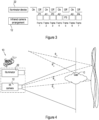
- the illuminator device 22 is switched between ON and OFF states in a temporal fashion corresponding to the frame rate in which frames, or IR images, FRAMES 1 to 7 are captured/acquired.
- the FRAMES 1-7 are indicated for illustrative purposes as in use there will be multiple frames acquired in this fashion as will be well understood by those skilled in the field of invention.
- the FRAMES 1-7 captures alternate between passive frames/images P1-P4 captured by the camera arrangement 12 whilst the illuminator device 22 is in an OFF state or in other words not radiating photons towards the scene 14, and active frames/images A1- A3 captured by the arrangement 12 whilst the illuminator device 22 is an ON state or in other words radiating photons towards the scene 14. It may thus be provided that the system 10 may operate between active and passive modes.
- the device 22 and arrangement 12 may be suitably calibrated so as to avoid scenarios where the consecutive frames acquired by the arrangement 12 are two consecutive active or passive frames.
- the device 22 and the arrangement 12 may be synchronized.
- the strobing frequency of the device 22 and the frame rate of the arrangement 12 may be synchronized with each other.
- either the arrangement 12 or the device 22 may be adapted so that active and passive images are consecutively captured in an alternate fashion.
- Strobing of the illuminator device 22 as described herein effectively increases the signal (gas) to noise (background) ratio of the system 10 thereby increasing the sensitivity thereof.
- a user of the system has a wider environment range in which to use the system 10, e.g., with sky as background, pipe as background, and the like. This is of course an obvious advantage over conventional active/passive detection schemes which do not necessarily have high signal to noise ratios which enable detection of gasses of interest with certain backgrounds.
- the strobing of the illuminator device 22 is relatively fast and thus the camera does not have time to move much between frames thereby eliminating the requirement for conventional active/passive systems having to keep the cameras very still to increase accuracy.
- the illuminator device 22 comprises a source in the form of an IR illuminator such as heated electrical filament configured to radiate photons, and a laser such as a quantum cascade laser configured to radiate photons, or the like.
- a source in the form of an IR illuminator such as heated electrical filament configured to radiate photons
- a laser such as a quantum cascade laser configured to radiate photons, or the like.
- the phrases “radiate photons towards the scene 14", “illuminate the scene 14", or “output light towards the scene”, etc. insofar as the illuminator device 12 is concerned all relate to the same principle of providing photons to the scene 12.
- the camera arrangement 12 may have a frame rate of approximately twice the strobing frequency of the illuminator device 22 so as to acquire two images in the single operating cycle (between ON and OFF states) of the device 22, viz., an active and passive image.
- the strobing frequency is between 5Hz and 30Hz
- the frame rate of the camera arrangement 12 is approximately twice that of the strobing frequency and is therefore approximately between 10Hz and 60Hz so as to capture both active and passive images in a consecutive fashion.
- the frame rate and strobing frequency may be synchronized in other ratios so as to ensure that the camera arrangement 12 acquires active and passive images consecutively in an alternating fashion as described herein, and illustrated in Figure 3 , at its respective frame rate.
- the arrangement 12 may have a frame rate of four times that of the strobing frequency, for example, obtaining four images in the single operating cycle of the device 22, i.e., two active and two passive images.
- the device 22 may be strobed or controlled to strobe in a plurality of different ways.
- the device 22 may be electronically controlled to strobe by switching the source/device 22 ON and OFF according to the predetermined strobing frequency.
- the system 10 may comprise a suitable mechanical/electromechanical shutter which is configured to block light radiating from the illuminator device 22/source or direct the illuminator device 22/source away from the scene 14 to achieve the desired strobing effect disclosed herein at the predetermined strobing frequency.
- the shutter may be electronically, mechanically, or electro-mechanically controlled.
- the strobing may be achieved by directing the source toward and away from the scene 14.
- the device 22 may be configured to direct photons to the scene 14 by pointing the source of photons to the scene and away from the scene 14.
- the strobing of the illuminator device 22 may be understood to therefore mean radiating photons to the scene 14 and not radiating photons to the scene 14 in an alternate fashion, by whatever means as will be understood by those skilled in the field of invention.
- the system 10 further comprises a processing arrangement 24.
- the processing arrangement 24 comprises one or more processors, for example, one or more central processing units, microcontrollers, microprocessors, field programmable gate arrays (FPGAs), application specific integrated circuits (ASICs), and the like and associated drivers, electronic components, etc. to achieve the functionality described herein.
- the arrangement 24 may comprise of one or more data storage devices / memory devices such as volatile memory and/or non-volatile memory such as flash memory, RAM (random access memory, ROM (read only memory), memory in the processors, or the like configured to store data including a set of computer executable instructions to control operation of the system 10.
- the arrangement 24 may control all the data and/or signal processing operations of the system 10.
- the arrangement 24 may comprise non-transitory computer-readable storage media which stored computer executable instructions which when executed by one or more processors, cause the same to control components of the system 10 and/or process data to provide outputs described herein.
- system 10 may comprise various conventional components such as drivers, circuitry, and other electronic components to achieve the functionality described herein. Moreover, it will be noted that the various components of the system 10 may be communicatively coupled to either each other and/or to the arrangement 24 via suitable wiring as will be well understood.
- the processing arrangement 24 may be configured to control the strobing of the illuminator device 22 in a predetermined fashion.
- the processing arrangement 24 may be configured to receive photocurrent from the detector 16, for example, via one or more internal or external analogue to digital components and process the same to generate digital signals representative of IR images at the predetermined frame rate.
- the arrangement 12 may be seen to form part of the arrangement 12.
- the arrangement 12 may alternately comprise one or more separate dedicated separate processors for generating images and/or signals representative thereof and transmit the same to the processor 24 for processing, though reference is made to the arrangement 24 for this purpose for ease of explanation.
- the data storage device (not shown) of the arrangement 24 is typically configured to store at least one prior frame obtained via the IR camera arrangement 12, for example, FRAME 1 (passive frame P1) which is acquired by the camera arrangement 12 is stored in the data storage device as a prior frame in a temporal fashion (e.g., at time t-1).
- FRAME 1 passive frame P1
- the term "frame” may be understood to refer to an "image" captured by the arrangement 12.
- the processor arrangement 24 is configured to compare at least one current frame obtained in a temporal fashion via the IR camera arrangement 12 (e.g. at time t) with the prior frame stored in the data storage device and generate an output signal in response to said comparison.
- a current FRAME 2 may be compared with stored FRAME 1 or in other words, active frame or image A1 is compared with passive frame or image P1, and so on in a continuous fashion. Multiple frames may be stored and associated with a consecutive temporal sequence, in use.
- a current frame/image may be understood to mean a frame/ image under consideration and prior frame/image may be understood to mean a frame/image which was acquired by the arrangement immediately before the current frame/image.
- the processor arrangement 24 is configured to compare the current and prior frame by determining a difference between the compared images, wherein the output signal is representative of the said difference between the compared images.
- the processor arrangement 24 may apply conventional image processing techniques in this regard.
- the output signal may correspond to a processed output image which is representative of the difference between the compared current and prior infrared signals.
- the output signal may correspond to a processed colour coded infrared image. Or other coloured image having pixels coloured based on the comparison.
- the coloured pixels in the processed output image may correspond to the flux absorbed by the gas to be detected.
- the term "signal" as it refers to images herein, such as infrared images, may be understood to be electrical signals which correspond to and/or are representative of images as will be understood by those skilled in the field of invention.
- the output signal generated by the processor arrangement 24 may be output infrared images and/or other processed images such as colour coded images as may be understood in the art.
- the output signals generated by the processor arrangement 24 may be representative of the output infrared image and/or other processed images.
- the arrangement 24 may compare more than one active and passive images, for example, in the case wherein the arrangement 12 captures two active and two passive images in one cycle of the device 22, the arrangement may compare two current infrared images active/passive with two prior infrared images passive/active to generate the output signal.
- the arrangement 12 may capture images (active and passive) of the scene during an inspection period or session wherein in the inspection period or session all active and passive frames are acquired and stored.
- the arrangement 24 is configured to compare current and prior frames in the temporal sequence in which they were acquired. This may be achieved in an off-line fashion/not completely in real-time or in real-time.
- the arrangement 12 may capture images (active and passive) of the scene during an inspection period or session wherein in the inspection period or session a current frame is acquired and stored as a prior frame, and the arrangement 24 is configured to compare the next frame (which is considered the current frame) with the stored prior frame.
- the stored prior frame is then discarded, e.g., deleted from the data storage device, and the frame which was considered the prior frame is then stored as the prior frame. This may be done for the duration of the inspection period. This implementation may be achieved substantially in real-time.
- the output signal is indicative of the absorbed flux by the gas to be detected.
- the output signal may thus be represented in various ways as described herein. In this regard, insofar as the flux absorbed by the gas cloud in the active and passive images is concerned reference will be made to Figures 4 and 5 of the drawings.
- the IR detector 16 in capturing a passive image, i.e., when the illuminator device 22 is OFF, the IR detector 16 will only receive ⁇ 4 and ⁇ 5 . However, when capturing an active image when the illuminator device 22 is on, the IR detector 16 will receive ( ⁇ 4 + ⁇ 2 ) and ( ⁇ 5 + ⁇ 3 ).
- the system 10 also comprises a display device 26 configured to display an output image based at least on the output signal generated by the processing arrangement 24 so as to facilitate detection of the particular predetermined gas, in use.
- the display device 26 may be a conventional LED (Light Emitting Diode) display, an LCD (Liquid Crystal Display), an O-LED (Organic LED) display, or the like.
- LED Light Emitting Diode
- LCD Liquid Crystal Display
- O-LED Organic LED
- the system 10 comprises a visible light camera arrangement 28 configured to acquire visible light images of the scene under observation 14.
- the visible light camera arrangement 28 is typically a conventional visible light video camera arrangement configured to acquire visible light video images.
- the processing arrangement 24 configured to combine the output signal generated thereby as described above in the aforementioned comparison with an output from the visible light camera arrangement to generate a combined signal representative of the flux absorbed as described herein superimposed onto a visible image of the scene under observation. This may be achieved via conventional image processing techniques well understood in the field of invention and in this way a user may easily observe a gas leak, if any, as an IR image superimposed on a visible light image.
- the arrangement 24 may be configured to apply image processing techniques to address any errors in the operation of the system 10 between ON and OFF strobing states. These image processing techniques may be well known to those skilled in the field of image processing.
- the processing described above is typically done in a streaming fashion, and substantially in real-time/near real-time, wherein output signals generated continuously in response to comparison between consecutive frames active and passive frames are continuously superimposed onto the visible images.
- the visible images generated by the arrangement 28 may be video images with a predetermined frame rate which may, for example, correspond to the frame rate of the IR camera arrangement 12.
- the system 10 also include a few additional features such as a laser pointer 30 in the form of an LED (Light Emitting Diode) pointer configured to generate a beam of light which may be used in a selective fashion in orienting the camera to the scene 14.
- a laser pointer 30 in the form of an LED (Light Emitting Diode) pointer configured to generate a beam of light which may be used in a selective fashion in orienting the camera to the scene 14.
- LED Light Emitting Diode
- the system 10 further comprises a power source 32 in the form of a re-chargeable portable battery locatable in the housing to power the system 10, as well as an I/O module 34 which allows data from the system 10 to be transferred from and to other computing devices, etc.
- the I/O module 34 may comprise suitable ports such as serial bus ports, jack ports, and the like.
- the system 10 may comprise a user interaction module 36 comprising one or more buttons, dials, touchscreens, voice recognition modules, and the like configured to receive user inputs and transmit the same to the processing arrangement 24 for controlling of the system 10 accordingly.
- the module 36 may be provided at an outer surface of the housing of the system 10 in a conventional fashion as a conventional camcorders and thus may comprise controls for standard features such as pan, and zoom, etc.
- the module 36 may in some example embodiments allow a user to be able to vary parameters of the system 10.
- FIG. 6 of the drawings where a block flow diagram of a method in accordance with an example embodiment of the invention is generally indicated by reference numeral 40.
- the method 40 is described with reference to the system 10 as described above for ease of understanding, but it will be appreciated by those skilled in the field of invention that the method 40 may be implemented by other systems, not illustrated, to achieve the functionality contemplated herein.
- the method 40 is typically a method for facilitating the detection of a gas as described above, for example in an electrical installation.
- the method 40 may comprise prior steps of selecting a system 10 matched to the gas to be detected and aiming the system 10 towards the equipment.
- various components of the system 10 may be selected to be suitable for use in detecting a particular gas.
- the method 40 may comprise prior steps of calibrating/synchronizing the camera arrangement 12 and the illuminator device 22 in a manner as described herein.
- the method 40 then comprises radiating photons, at block 42, at a predetermined wavelength towards the scene under observation in a strobed fashion at a predetermined strobing frequency. This step may be done by controlling the device 22 as described above using a suitable shutter and/or other means.
- the method 40 comprises simultaneously as the step 42, acquiring infrared images, at block 44, from the scene under observation at a frame rate associated with the strobing frequency by way of the camera arrangement 12 as described above.
- active images are acquired during the ON state of the illuminator device 22, and passive images are acquired during the OFF state of the illuminator device 22 in an alternating consecutive fashion meaning that an active image is acquired after a passive image, and vice versa as illustrated in Figure 3 .
- the method 40 then comprises storing, at block 46, at least a prior frame acquired from the scene 14 under observation in a data storage device or means.
- the method 40 then comprises comparing, at block 48, at least one current frame acquired with the stored at least one prior frame by way of the processing arrangement 24 as described above, so as to generate an output signal, at block 50, in response to said comparison.
- the method 40 comprises comparing active and passive infrared frames. These active and passive frames which are compared are captured and compared in a temporal fashion wherein a current active/passive infrared frame is compared with a previously captured prior passive/active infrared frame.
- the step of comparing may be to determine the differences between the current and prior frames, and thus the amount of flux absorbed by the target gas as described above. This may be achieved by subtracting the current frame from the prior frame or vice versa, wherein the output signal is representative of the differences between the current frame and the prior frame and thus the amount of flux absorbed by the gas to be detected.
- the method 40 then comprises displaying, at block 52, an output image on the display device 26 based at least on the generated output signal so as to facilitate detection of the particular predetermined gas.
- the step 52 may comprise overlaying an IR image or other processed image such as a colour coded image representative of the generated output signal from step 50 onto an acquired visible video image so as to be able to interpret from the overlay that a gas is present in the scene under observation 14.
- the output signal may thus be a processed image having pixels corresponding to the flux absorbed by the gas to be detected coloured so as to facilitate the visualization of the gas leak, if any, in use.
- the method 40 may be repeated until the inspection of a scene 14 is completed. In other words, the method 40 may be repeated until the inspection session is over.
- system 10 may comprise of a mass storage device to store pictures and videos of the scene 14. These pictures and videos can be displayed or played back or transferred to other devices to be displayed or played back later.
- the system 10 may comprise of a device to send the output image to another device or system in real time (video streaming).
- the system 10 may have a means of being remotely controlled, for example, by way a suitable controller and receiver associated with the system 10, wherein the receiver is configured to receive signals representative of control signals from the controller (for example, wirelessly from a remote controller) thereby to control operation of the system 10.
- a suitable controller and receiver associated with the system 10 wherein the receiver is configured to receive signals representative of control signals from the controller (for example, wirelessly from a remote controller) thereby to control operation of the system 10.
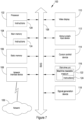
- Figure 7 shows a diagrammatic representation of machine in the example of a computer system 100 within which a set of instructions, for causing the machine to perform any one or more of the methodologies discussed herein, may be executed.
- the machine operates as a standalone device or may be connected (e.g., networked) to other machines.
- the machine may operate in the capacity of a server or a client machine in server-client network environment, or as a peer machine in a peer-to-peer (or distributed) network environment.
- the machine may be a personal computer (PC), a tablet PC, a set-top box (STB), a Personal Digital Assistant (PDA), a cellular telephone, a web appliance, a network router, switch or bridge, or any machine capable of executing a set of instructions (sequential or otherwise) that specify actions to be taken by that machine.
- PC personal computer
- PDA Personal Digital Assistant
- STB set-top box
- WPA Personal Digital Assistant
- a cellular telephone a web appliance
- network router switch or bridge
- machine any machine capable of executing a set of instructions (sequential or otherwise) that specify actions to be taken by that machine.
- machine shall also be taken to include any collection of machines, including virtual machines, that individually or jointly execute a set (or multiple sets) of instructions to perform any one or more of the methodologies discussed herein.
- the example computer system 100 includes a processor 102 (e.g., a central processing unit (CPU), a graphics processing unit (GPU) or both), a main memory 104 and a static memory 106, which communicate with each other via a bus 108.
- the computer system 100 may further include a video display unit 110 (e.g., a liquid crystal display (LCD) or a cathode ray tube (CRT)).
- the computer system 100 also includes an alphanumeric input device 112 (e.g., a keyboard), a user interface (UI) navigation device 114 (e.g., a mouse, or touchpad), a disk drive unit 116, a signal generation device 118 (e.g., a speaker) and a network interface device 120.
- UI user interface
- the computer system 100 also includes an alphanumeric input device 112 (e.g., a keyboard), a user interface (UI) navigation device 114 (e.g., a mouse, or touchpad), a disk drive unit 116, a signal generation device 118 (e.g., a speaker) and a network interface device 120.
- UI user interface
- a signal generation device 118 e.g., a speaker
- the disk drive unit 16 includes a machine-readable medium 122 storing one or more sets of instructions and data structures (e.g., software 124) embodying or utilised by any one or more of the methodologies or functions described herein.
- the software 124 may also reside, completely or at least partially, within the main memory 104 and/or within the processor 102 during execution thereof by the computer system 100, the main memory 104 and the processor 102 also constituting machine-readable media.
- the software 124 may further be transmitted or received over a network 126 via the network interface device 120 utilising any one of a number of well-known transfer protocols (e.g., HTTP).
- HTTP transfer protocol
- machine-readable medium 122 is shown in an example embodiment to be a single medium, the term “machine-readable medium” may refer to a single medium or multiple media (e.g., a centralized or distributed database, and/or associated caches and servers) that store the one or more sets of instructions.
- the term “machine-readable medium” may also be taken to include any medium that is capable of storing, encoding or carrying a set of instructions for execution by the machine and that cause the machine to perform any one or more of the methodologies of the present disclosure, or that is capable of storing, encoding or carrying data structures utilised by or associated with such a set of instructions.
- the term “machine-readable medium” may accordingly be taken to include, but not be limited to, solid-state memories, optical and magnetic media, and carrier wave signals.
Landscapes
- Physics & Mathematics (AREA)
- General Physics & Mathematics (AREA)
- Spectroscopy & Molecular Physics (AREA)
- Chemical & Material Sciences (AREA)
- Life Sciences & Earth Sciences (AREA)
- Analytical Chemistry (AREA)
- Biochemistry (AREA)
- General Health & Medical Sciences (AREA)
- Health & Medical Sciences (AREA)
- Immunology (AREA)
- Pathology (AREA)
- Studio Devices (AREA)
- Transforming Light Signals Into Electric Signals (AREA)
- Examining Or Testing Airtightness (AREA)
- Photometry And Measurement Of Optical Pulse Characteristics (AREA)
- Closed-Circuit Television Systems (AREA)
Claims (15)
- System (10) zum Detektieren eines vorgegebenen Zielgases in einer beobachteten Szene, wobei das System (10) umfasst:ein Gehäuse, wobei sich das gesamte oder ein Großteil des Systems (10) in dem Gehäuse befindet;eine Infrarotkameraanordnung (12), die dazu konfiguriert ist, Infrarotbilder der beobachteten Szene mit einer vorgegebenen Bildfrequenz aufzunehmen,eine Beleuchtungsvorrichtung (22), die dazu konfiguriert ist, Photonen mit einer vorgegebenen Wellenlänge, bei oder in der Nähe einer Absorptionswellenlänge des bestimmten vorgegebenen Zielgases, das zur Detektion ausgewählt wurde, auf die beobachtete Szene abzustrahlen, wobei die Beleuchtungsvorrichtung mit einer vorgegebenen Stroboskopfrequenz zwischen einem EIN-Zustand, in dem Photonen mit der vorgegebenen Wellenlänge auf die beobachtete Szene abgestrahlt werden, und einem AUS-Zustand, in dem keine Photonen der vorgegebenen Wellenlänge auf die beobachtete Szene abgestrahlt werden, stroboskopisch betätigt wird und wobei die Stroboskopfrequenz der Beleuchtungsvorrichtung (22) mit der vorgegebenen Bildfrequenz der Infrarotkameraanordnung (12) so verknüpft ist, dass während des EIN-Zustands der Beleuchtungsvorrichtung (22) aktive Infrarotbilder von der Infrarotkameraanordnung (12) aufgenommen werden und während des AUS-Zustands der Beleuchtungsvorrichtung (22) passive Infrarotbilder von der Infrarotkameraanordnung (12) aufgenommen werden, und zwar in abwechselnder Weise mit der vorgegebenen Bildfrequenz,eine Verarbeitungsanordnung (24), wobei die Verarbeitungsanordnung (24) umfasst:ein Daten-Speichergerät, das dazu konfiguriert ist, mindestens ein vorheriges von der Infrarotkameraanordnung (12) aufgenommenes Infrarotbild zu speichern; undmindestens einen Prozessor, der konfiguriert ist zum:kontinuierlichen Vergleichen von mindestens einem aktuellen Infrarotbild, das von derInfrarotkameraanordnung (12) aufgenommen wird, mit dem mindestens einen vorherigen Infrarotbild, das von der Infrarotkameraanordnung (12) unmittelbar vor dem mindestens einen aktuellen Infrarotbild aufgenommen und in der Datenspeichervorrichtung gespeichert wurde, indem Unterschiede zwischen dem mindestens einen aktuellen Infrarotbild und dem mindestens einen vorherigen Infrarotbild und somit die Menge des von dem vorbestimmten Zielgas absorbierten Beleuchtungsphotonenflusses ermittelt werden, wobei das mindestens eine aktuelle Infrarotbild abwechselnd ein aktives Infrarotbild und ein passives Infrarotbild ist und das jeweilige mindestens eine vorherige Infrarotbild abwechselnd ein passives Infrarotbild und ein aktives Infrarotbild ist, und Erzeugen eines Ausgabesignals als Reaktion auf den Vergleich,wobei das Ausgabesignal repräsentativ ist für die Unterschiede zwischen dem mindestens einen aktuellen Infrarotbild und dem mindestens einen vorherigen Infrarotbild, undeine Anzeigevorrichtung (26), die dazu konfiguriert ist, ein Ausgabebild basierend zumindest auf dem von der Verarbeitungsanordnung (24) erzeugten Ausgabesignal anzuzeigen, um im Gebrauch die Detektion des bestimmten vorgegebenen Zielgases zu ermöglichen.
- System (10) nach Anspruch 1, wobei der Prozessor dazu konfiguriert ist, das mindestens eine aktuelle Infrarotbild und das mindestens eine vorherige Infrarotbild zu vergleichen, indem er diese voneinander subtrahiert.
- System (10) nach Anspruch 1 oder Anspruch 2, wobei die vorgegebene Bildfrequenz mit der vorgegebenen Stroboskopfrequenz insofern verknüpft ist, als dass die vorgegebene Bildfrequenz mit der vorgegebenen Stroboskopfrequenz in Beziehung steht, wobei die vorgegebene Bildfrequenz ein Vielfaches der vorgegebenen Stroboskopfrequenz ist, so dass die Infrarotkameraanordnung (12) in jedem Stroboskopzyklus der Stroboskopfrequenz mehrere aktive und passive Infrarotbilder aufnimmt.
- System (10) nach einem der vorhergehenden Ansprüche, wobei die vorgegebene Bildfrequenz mit der vorgegebenen Stroboskopfrequenz insofern verknüpft ist, als dass die vorgegebene Bildfrequenz ein gerades Vielfaches der vorgegebenen Stroboskopfrequenz ist, und wobei die vorgegebene Bildfrequenz mindestens das Doppelte oder Vierfache der vorgegebenen Stroboskopfrequenz beträgt, wobei die Verarbeitungsanordnung (24) dazu konfiguriert ist, in einem Stroboskopzyklus der Beleuchtungsvorrichtung (24) dieselbe Anzahl von aktiven und passiven Infrarotbildern zu vergleichen.
- System (10) nach einem der vorhergehenden Ansprüche, wobei die Prozessoranordnung (24) dazu konfiguriert ist, mehrere aktive und passive Infrarotbilder zu vergleichen, die in einem Stroboskopzyklus der Beleuchtungsvorrichtung (24) aufgenommen wurden.
- System nach einem der vorhergehenden Ansprüche, wobei das Ausgabesignal einem verarbeiteten Ausgabebild entspricht, das repräsentativ ist für die Unterschiede zwischen dem mindestens einen aktuellen Infrarotbild und dem mindestens einen vorherigen Infrarotbild, wobei das verarbeitete Ausgabebild bezeichnend ist für eine Menge des Beleuchtungsphotonenflusses, der vom Zielgas absorbiert wird, das detektiert werden soll.
- System nach einem der vorhergehenden Ansprüche, wobei die Infrarotkameraanordnung eine Infrarotvideokameraanordnung ist, die dazu konfiguriert ist, kontinuierlich Infrarotvideobilder aufzunehmen, wobei das System eine Kameraanordnung (28) für sichtbares Licht umfasst, die dazu konfiguriert ist, Bilder im sichtbaren Licht der beobachteten Szene aufzunehmen,
wobei die Infrarotkameraanordnung und die Kameraanordnung für sichtbares Licht im Wesentlichen dasselbe oder ein ähnliches Sichtfeld aufweisen, und wobei die Kameraanordnung für sichtbares Licht eine Videokameraanordnung für sichtbares Licht ist, die dazu konfiguriert ist, Videobilder im sichtbaren Licht aufzunehmen, und wobei die Verarbeitungsanordnung dazu konfiguriert ist, das dadurch erzeugte Ausgabesignal mit einer Ausgabe von der Kameraanordnung für sichtbares Licht zu kombinieren, um ein kombiniertes Signal zu erzeugen, das repräsentativ ist für ein Infrarotbild der beobachteten Szene, das einem sichtbaren Bild der beobachteten Szene überlagert ist, wobei das kombinierte Signal dem von der Anzeigevorrichtung angezeigten Ausgabebild entspricht. - System (10) nach einem der vorhergehenden Ansprüche, wobei die Beleuchtungsvorrichtung (22) aus einer Gruppe ausgewählt ist, die einen Infrarot-Beleuchter und einen Laser umfasst, wobei der Infrarot-Beleuchter die Form einer beheizten elektrischen Glühfadenanordnung hat und wobei der Laser die Form eines Quantenkaskadenlasers hat.
- System (10) nach einem der vorhergehenden Ansprüche, wobei das Gehäuse ein thermisch isoliertes Fach zum Einschließen aller oder eines Großteils der Komponenten der Infrarotkameraanordnung definiert und wobei das System eine geeignete Kühlanordnung zum Kühlen von zumindest Komponenten des Systems umfasst, die sich im Gehäuse befinden; und/oder wobei die Anzeigevorrichtung innerhalb des Gehäuses vorgesehen ist und wobei das Gehäuse ein Okular umfasst, das mit der Anzeigevorrichtung ausgerichtet ist, so dass Benutzer in der Lage sind, die Anzeigevorrichtung innerhalb des Gehäuses durch das Okular zu betrachten; und/oder wobei das System einen Laserpointer (30) umfasst, um einen Benutzer dabei zu unterstützen, das System auf die beobachtete Szene auszurichten.
- Verfahren (40) zum Detektieren eines vorgegebenen Zielgases, wobei das Verfahren (40) umfasst:Abstrahlen von Photonen (42) mit einer vorgegebenen Wellenlänge, bei oder in der Nähe einer Absorptionswellenlänge des bestimmten vorgegebenen Zielgases, das zur Detektion ausgewählt wurde, in Richtung einer beobachteten Szene in einer stroboskopartigen Weise mit einer vorgegebenen Stroboskopfrequenz derart, dass Photonen mit der vorgegebenen Wellenlänge auf die beobachtete Szene abgestrahlt werden und Photonen mit der vorgegebenen Wellenlänge nicht auf die beobachtete Szene abgestrahlt werden, und zwar in abwechselnder Weise entsprechend der vorgegebenen Stroboskopfrequenz;Aufnehmen von Infrarotbildern (44) von der beobachteten Szene mit einer vorgegebenen Bildfrequenz, wobei die vorgegebene Bildfrequenz mit der vorgegebenen Stroboskopfrequenz so verknüpft ist, dass aktive Infrarotbilder aufgenommen werden, während Photonen mit der vorgegebenen Wellenlänge auf die beobachtete Szene abgestrahlt werden, und passive Infrarotbilder aufgenommen werden, während Photonen mit der vorgegebenen Wellenlänge nicht auf die beobachtete Szene abgestrahlt werden, und zwar in abwechselnder Weise mit der vorgegebenen Bildfrequenz,Speichern (46) von mindestens einem vorherigen Infrarotbild, das von der beobachteten Szene aufgenommen wurde,kontinuierliches Vergleichen (48) von mindestens einem aufgenommenen aktuellen Infrarotbild mit dem gespeicherten mindestens einen vorherigen Infrarotbild, das unmittelbar vor dem mindestens einen aktuellen Infrarotbild aufgenommen wurde, indem die Unterschiede zwischen dem mindestens einen aktuellen Infrarotbild und dem mindestens einen vorherigen Infrarotbild ermittelt werden,und somit die Menge des Beleuchtungsphotonenflusses, der vom vorgegebenen Zielgas absorbiert wird, wobei das mindestens eine aktuelle Infrarotbild abwechselnd ein aktives Infrarotbild und ein passives Infrarotbild ist und das jeweilige mindestens eine vorherige Infrarotbild abwechselnd ein passives Infrarotbild und ein aktives Infrarotbild ist,Erzeugen (50) eines Ausgabesignals als Reaktion auf den Vergleich, wobei das Ausgabesignal repräsentativ ist für die Unterschiede zwischen dem mindestens einen aktuellenInfrarotbild und dem mindestens einen vorherigen Infrarotbild, undAnzeigen (52) eines Ausgabebildes auf einer Anzeigevorrichtung basierend zumindest auf dem erzeugten Ausgabesignal, um die Detektion des bestimmten vorgegebenen Zielgases zu ermöglichen.
- Verfahren (40) nach Anspruch 10, wobei der Schritt des Vergleichens (48) das Subtrahieren des aktuellen Infrarotbildes vom vorherigen Infrarotbild oder umgekehrt umfasst.
- Verfahren (40) nach Anspruch 10 oder 11, wobei das Verfahren (40) das Abstrahlen von Photonen mit der vorgegebenen Wellenlänge in Richtung der Szene für einen vorgegebenen Zeitraum und das gleichzeitige Aufnehmen von mindestens einem aktiven Infrarotbild der Szene und das Nichtabstrahlen von Photonen mit der vorgegebenen Wellenlänge in Richtung der Szene für einen vorgegebenen Zeitraum und das gleichzeitige Aufnehmen von mindestens einem passiven Infrarotbild der Szene umfasst, wobei die aktiven und passiven Bilder mit der vorgegebenen Bildfrequenz aufgenommen werden und die vorgegebenen Zeiträume, in denen Photonen in Richtung der Szene abgestrahlt werden oder nicht, auf der vorgegebenen Stroboskopfrequenz basieren.
- Verfahren (40) nach einem der Ansprüche 10 bis 12, wobei die vorgegebene Bildfrequenz mit der vorgegebenen Stroboskopfrequenz insofern verknüpft ist, als dass die vorgegebene Bildfrequenz ein Vielfaches der vorgegebenen Stroboskopfrequenz ist, und wobei das Verfahren das Vergleichen von mehreren aktiven und passiven Infrarotbildern umfasst.
- Verfahren (40) nach einem der Ansprüche 10 bis 13, wobei die vorgegebene Bildfrequenz mit der vorgegebenen Stroboskopfrequenz insofern verknüpft ist, als dass die vorgegebene Bildfrequenz ein gerades Vielfaches der vorgegebenen Stroboskopfrequenz ist, wobei die vorgegebene Bildfrequenz etwa das Zweifache oder Vierfache der vorgegebenen Stroboskopfrequenz beträgt.
- Verfahren (40) nach einem der Ansprüche 10 bis 14, wobei das Verfahren (40) umfasst:Aufnehmen von Bildern im sichtbaren Licht der beobachteten Szene,Kombinieren des erzeugten Ausgabesignals mit einem Signal, das repräsentativ ist für ein aufgenommenes Bild im sichtbaren Licht, um ein kombiniertes Signal zu erzeugen, das repräsentativ ist für ein Bild der beobachteten Szene, das auf ein sichtbares Bild der beobachteten Szene überlagert ist, undAnzeigen des kombinierten Signals auf der Anzeigevorrichtung.
Applications Claiming Priority (2)
| Application Number | Priority Date | Filing Date | Title |
|---|---|---|---|
| GB1716534.1A GB2567246A (en) | 2017-10-09 | 2017-10-09 | A gas detection system and method |
| PCT/IB2018/057808 WO2019073377A1 (en) | 2017-10-09 | 2018-10-09 | SYSTEM AND METHOD FOR DETECTING GAS |
Publications (3)
| Publication Number | Publication Date |
|---|---|
| EP3676597A1 EP3676597A1 (de) | 2020-07-08 |
| EP3676597C0 EP3676597C0 (de) | 2024-07-24 |
| EP3676597B1 true EP3676597B1 (de) | 2024-07-24 |
Family
ID=60326968
Family Applications (1)
| Application Number | Title | Priority Date | Filing Date |
|---|---|---|---|
| EP18792535.9A Active EP3676597B1 (de) | 2017-10-09 | 2018-10-09 | Gasdetektionssystem und -verfahren |
Country Status (7)
| Country | Link |
|---|---|
| US (2) | US11585751B2 (de) |
| EP (1) | EP3676597B1 (de) |
| KR (1) | KR102596253B1 (de) |
| CN (1) | CN111433591B (de) |
| GB (1) | GB2567246A (de) |
| WO (1) | WO2019073377A1 (de) |
| ZA (2) | ZA202001815B (de) |
Families Citing this family (19)
| Publication number | Priority date | Publication date | Assignee | Title |
|---|---|---|---|---|
| US11598716B2 (en) * | 2017-09-27 | 2023-03-07 | Konica Minolta, Inc. | Gas image device and image acquisition method |
| WO2020235165A1 (ja) * | 2019-05-20 | 2020-11-26 | コニカミノルタ株式会社 | 検査データ管理システム、検査装置および検査データ送信方法 |
| WO2021095112A1 (ja) * | 2019-11-12 | 2021-05-20 | コニカミノルタ株式会社 | ガス検知装置、画像処理制御方法および画像処理制御プログラム |
| JP7540194B2 (ja) * | 2020-05-18 | 2024-08-27 | 中国電力株式会社 | 気中開閉器の浸水判定装置 |
| US11808260B2 (en) * | 2020-06-15 | 2023-11-07 | Schlumberger Technology Corporation | Mud pump valve leak detection and forecasting |
| WO2022069031A1 (en) | 2020-09-30 | 2022-04-07 | Trimble Ab | Method for operating a geodetic instrument, and related geodetic instrument |
| JP6918194B1 (ja) * | 2020-12-17 | 2021-08-11 | 東京瓦斯株式会社 | 表示装置、プログラム、ガス漏洩検知システム及びガス漏洩検知方法 |
| KR102309680B1 (ko) * | 2021-05-10 | 2021-10-08 | 국방과학연구소 | 주성분 분석 기법을 이용한 초분광 영상 실시간 독성 화학가스 탐지 방법 및 이를 실행시키기 위한 프로그램을 기록한 컴퓨터 판독 가능한 기록 매체 |
| DE102021131832A1 (de) * | 2021-12-02 | 2023-06-07 | Endress+Hauser Group Services Ag | Vorrichtung zum Detektieren eines Gases oder eines mehrkomponentigen Gasgemisches |
| CN114199464A (zh) * | 2021-12-09 | 2022-03-18 | 湖北久之洋信息科技有限公司 | 一种实现视频显控的sf6气体检漏手持设备 |
| US12297722B2 (en) | 2022-02-03 | 2025-05-13 | Saudi Arabian Oil Company | Total crude oil demand control from multiple oil stabilizer columns |
| DE102022105056A1 (de) | 2022-03-03 | 2023-09-07 | Grandperspective GmbH | Mobiler Gassensor und Verfahren zur Detektion und Abbildung von Gasemissionen |
| CN115545066B (zh) * | 2022-04-20 | 2025-08-08 | 珠海富鸿科技有限公司 | 一种基于自适应滤波算法的湿度补偿方法及系统 |
| KR102517477B1 (ko) * | 2022-07-20 | 2023-04-05 | (주)하이브시스템 | 인공지능 기반 유해 가스 누출 원점을 식별하는 방법 및 장치 |
| KR102517478B1 (ko) * | 2022-07-20 | 2023-04-05 | (주)하이브시스템 | 인공지능 기반 유해 가스 누출 여부를 결정하는 방법 및 장치 |
| KR102482129B1 (ko) * | 2022-07-20 | 2023-01-02 | (주)하이브시스템 | 인공지능 기반 유해 가스 누출 탐지 시스템 및 이의 동작 방법 |
| US12207022B2 (en) | 2023-04-03 | 2025-01-21 | Championx Llc | Optical gas imaging camera with navigation and targeting control, learning and operating methods for the camera, and compliance auditing system |
| SE546545C2 (en) * | 2023-04-05 | 2024-11-26 | Beamonics Ab | Gas sensing surveillance system based on tunable diode laser absorption spectroscopy |
| CN117218128B (zh) * | 2023-11-09 | 2024-03-22 | 成都格理特电子技术有限公司 | 一种整合时序信息的跑冒滴漏目标检测方法及系统 |
Family Cites Families (11)
| Publication number | Priority date | Publication date | Assignee | Title |
|---|---|---|---|---|
| US5001346A (en) * | 1990-02-26 | 1991-03-19 | Rockwell International Corporation | Leak detection system with background compensation |
| US5656813A (en) * | 1995-04-04 | 1997-08-12 | Gmd Systems, Inc. | Apparatus for imaging gas |
| US6157033A (en) * | 1998-05-18 | 2000-12-05 | Power Distribution Services, Inc. | Leak detection system |
| US8659664B2 (en) * | 2007-03-23 | 2014-02-25 | Flir Systems, Inc. | Thermography camera configured for leak detection |
| US8330957B2 (en) * | 2009-06-29 | 2012-12-11 | Hager Enviromental and Atmospheric Technologies, LLC | Device and method for quantification of gases in plumes by remote sensing |
| CN103503135A (zh) * | 2011-03-25 | 2014-01-08 | 埃克森美孚上游研究公司 | 用于气体羽状流检测的差分红外线成像仪 |
| KR101131095B1 (ko) * | 2011-06-10 | 2012-04-02 | 주식회사 창성에이스산업 | 가스누설감지 시스템 및 방법 |
| CN102393375A (zh) * | 2011-08-24 | 2012-03-28 | 北京广微积电科技有限公司 | 一种被动式气体成像系统 |
| WO2014143338A2 (en) * | 2012-12-21 | 2014-09-18 | Flir Systems, Inc. | Imager with array of multiple infrared imaging modules |
| US9464984B2 (en) * | 2014-06-20 | 2016-10-11 | Fluke Corporation | Laser illuminated gas imaging device for determining inoperable gas detection pixels |
| US20170138813A1 (en) * | 2015-11-13 | 2017-05-18 | General Electric Company | System and method for detecting leaks in generators |
-
2017
- 2017-10-09 GB GB1716534.1A patent/GB2567246A/en not_active Withdrawn
-
2018
- 2018-10-09 US US16/754,683 patent/US11585751B2/en active Active
- 2018-10-09 CN CN201880065933.5A patent/CN111433591B/zh active Active
- 2018-10-09 EP EP18792535.9A patent/EP3676597B1/de active Active
- 2018-10-09 KR KR1020207012020A patent/KR102596253B1/ko active Active
- 2018-10-09 WO PCT/IB2018/057808 patent/WO2019073377A1/en not_active Ceased
-
2020
- 2020-03-23 ZA ZA2020/01815A patent/ZA202001815B/en unknown
-
2023
- 2023-02-21 US US18/112,364 patent/US11927529B2/en active Active
- 2023-08-31 ZA ZA2023/08438A patent/ZA202308438B/en unknown
Also Published As
| Publication number | Publication date |
|---|---|
| GB201716534D0 (en) | 2017-11-22 |
| ZA202001815B (en) | 2024-01-31 |
| WO2019073377A1 (en) | 2019-04-18 |
| KR20200088304A (ko) | 2020-07-22 |
| RU2020115497A (ru) | 2021-11-12 |
| US20230194420A1 (en) | 2023-06-22 |
| CN111433591B (zh) | 2023-07-25 |
| GB2567246A (en) | 2019-04-10 |
| CN111433591A (zh) | 2020-07-17 |
| EP3676597C0 (de) | 2024-07-24 |
| KR102596253B1 (ko) | 2023-11-01 |
| US11927529B2 (en) | 2024-03-12 |
| US11585751B2 (en) | 2023-02-21 |
| ZA202308438B (en) | 2024-10-30 |
| EP3676597A1 (de) | 2020-07-08 |
| US20200363327A1 (en) | 2020-11-19 |
Similar Documents
| Publication | Publication Date | Title |
|---|---|---|
| US11927529B2 (en) | Gas detection system and method | |
| US9633426B2 (en) | Remote visual inspection image capture system and method | |
| KR101854188B1 (ko) | 3차원 영상 획득 장치 및 3차원 영상 획득 장치에서 깊이 정보 산출 방법 | |
| US8907282B2 (en) | Thermal imaging camera with intermittent image capture | |
| JP5647430B2 (ja) | スペースデブリ観測方法 | |
| US20170048494A1 (en) | Underwater surveys | |
| CN105227815B (zh) | 一种被动式单像素望远成像方法 | |
| CN111982023A (zh) | 图像捕捉装置组件、三维形状测量装置和运动检测装置 | |
| CN110779625B (zh) | 一种四维超快摄影装置 | |
| JP2004045266A (ja) | 3次元情報検出方法及び装置 | |
| US9654741B2 (en) | System and method for optical fiber based image acquisition suitable for use in turbine engines | |
| JP2019027894A (ja) | 位置情報取得システム、位置情報取得方法及びプログラム | |
| DE102016219388A1 (de) | Verfahren zur kontaktfreien Ermittlung einer zweidimensionalen Temperaturinformation sowie Wärmebildkamera | |
| RU2790013C2 (ru) | Система и способ обнаружения газа | |
| JP4972423B2 (ja) | カメラ装置及びその制御方法 | |
| JP7669502B2 (ja) | アクティブイメージングシステム | |
| CN205029743U (zh) | 一种被动式单像素望远成像系统 | |
| WO2019181125A1 (ja) | 画像処理装置及び画像処理方法 | |
| WO2020235165A1 (ja) | 検査データ管理システム、検査装置および検査データ送信方法 | |
| WO2024233924A3 (en) | Leak-detection system and methods for leak detection | |
| JP2025129547A (ja) | 仮想画像を生成するためのシステム、システムの制御方法及びシステムのプログラム | |
| RU2663537C1 (ru) | Оптико-электронное устройство | |
| Oja et al. | Stand-alone Dual Sensing Single Pixel Camera in SWIR | |
| Zhou et al. | The MRC method for watched directly imaging system | |
| KR20120061119A (ko) | 다방향 수중 촬영 시스템 |
Legal Events
| Date | Code | Title | Description |
|---|---|---|---|
| STAA | Information on the status of an ep patent application or granted ep patent |
Free format text: STATUS: UNKNOWN |
|
| STAA | Information on the status of an ep patent application or granted ep patent |
Free format text: STATUS: THE INTERNATIONAL PUBLICATION HAS BEEN MADE |
|
| PUAI | Public reference made under article 153(3) epc to a published international application that has entered the european phase |
Free format text: ORIGINAL CODE: 0009012 |
|
| STAA | Information on the status of an ep patent application or granted ep patent |
Free format text: STATUS: REQUEST FOR EXAMINATION WAS MADE |
|
| 17P | Request for examination filed |
Effective date: 20200401 |
|
| AK | Designated contracting states |
Kind code of ref document: A1 Designated state(s): AL AT BE BG CH CY CZ DE DK EE ES FI FR GB GR HR HU IE IS IT LI LT LU LV MC MK MT NL NO PL PT RO RS SE SI SK SM TR |
|
| AX | Request for extension of the european patent |
Extension state: BA ME |
|
| DAV | Request for validation of the european patent (deleted) | ||
| DAX | Request for extension of the european patent (deleted) | ||
| STAA | Information on the status of an ep patent application or granted ep patent |
Free format text: STATUS: EXAMINATION IS IN PROGRESS |
|
| 17Q | First examination report despatched |
Effective date: 20220304 |
|
| GRAP | Despatch of communication of intention to grant a patent |
Free format text: ORIGINAL CODE: EPIDOSNIGR1 |
|
| STAA | Information on the status of an ep patent application or granted ep patent |
Free format text: STATUS: GRANT OF PATENT IS INTENDED |
|
| RIC1 | Information provided on ipc code assigned before grant |
Ipc: G01M 3/38 20060101ALN20240126BHEP Ipc: G01N 21/35 20140101ALN20240126BHEP Ipc: G01N 21/17 20060101ALN20240126BHEP Ipc: G01N 21/3504 20140101AFI20240126BHEP |
|
| INTG | Intention to grant announced |
Effective date: 20240214 |
|
| GRAS | Grant fee paid |
Free format text: ORIGINAL CODE: EPIDOSNIGR3 |
|
| GRAA | (expected) grant |
Free format text: ORIGINAL CODE: 0009210 |
|
| STAA | Information on the status of an ep patent application or granted ep patent |
Free format text: STATUS: THE PATENT HAS BEEN GRANTED |
|
| RIN1 | Information on inventor provided before grant (corrected) |
Inventor name: COX, ETTIENNE |
|
| AK | Designated contracting states |
Kind code of ref document: B1 Designated state(s): AL AT BE BG CH CY CZ DE DK EE ES FI FR GB GR HR HU IE IS IT LI LT LU LV MC MK MT NL NO PL PT RO RS SE SI SK SM TR |
|
| REG | Reference to a national code |
Ref country code: GB Ref legal event code: FG4D |
|
| REG | Reference to a national code |
Ref country code: CH Ref legal event code: EP |
|
| REG | Reference to a national code |
Ref country code: IE Ref legal event code: FG4D Ref country code: DE Ref legal event code: R096 Ref document number: 602018072226 Country of ref document: DE |
|
| U01 | Request for unitary effect filed |
Effective date: 20240826 |
|
| U07 | Unitary effect registered |
Designated state(s): AT BE BG DE DK EE FI FR IT LT LU LV MT NL PT RO SE SI Effective date: 20240920 |
|
| U20 | Renewal fee for the european patent with unitary effect paid |
Year of fee payment: 7 Effective date: 20240927 |
|
| PG25 | Lapsed in a contracting state [announced via postgrant information from national office to epo] |
Ref country code: NO Free format text: LAPSE BECAUSE OF FAILURE TO SUBMIT A TRANSLATION OF THE DESCRIPTION OR TO PAY THE FEE WITHIN THE PRESCRIBED TIME-LIMIT Effective date: 20241024 |
|
| PG25 | Lapsed in a contracting state [announced via postgrant information from national office to epo] |
Ref country code: GR Free format text: LAPSE BECAUSE OF FAILURE TO SUBMIT A TRANSLATION OF THE DESCRIPTION OR TO PAY THE FEE WITHIN THE PRESCRIBED TIME-LIMIT Effective date: 20241025 Ref country code: PL Free format text: LAPSE BECAUSE OF FAILURE TO SUBMIT A TRANSLATION OF THE DESCRIPTION OR TO PAY THE FEE WITHIN THE PRESCRIBED TIME-LIMIT Effective date: 20240724 |
|
| PG25 | Lapsed in a contracting state [announced via postgrant information from national office to epo] |
Ref country code: IS Free format text: LAPSE BECAUSE OF FAILURE TO SUBMIT A TRANSLATION OF THE DESCRIPTION OR TO PAY THE FEE WITHIN THE PRESCRIBED TIME-LIMIT Effective date: 20241124 |
|
| PG25 | Lapsed in a contracting state [announced via postgrant information from national office to epo] |
Ref country code: HR Free format text: LAPSE BECAUSE OF FAILURE TO SUBMIT A TRANSLATION OF THE DESCRIPTION OR TO PAY THE FEE WITHIN THE PRESCRIBED TIME-LIMIT Effective date: 20240724 |
|
| PG25 | Lapsed in a contracting state [announced via postgrant information from national office to epo] |
Ref country code: RS Free format text: LAPSE BECAUSE OF FAILURE TO SUBMIT A TRANSLATION OF THE DESCRIPTION OR TO PAY THE FEE WITHIN THE PRESCRIBED TIME-LIMIT Effective date: 20241024 Ref country code: ES Free format text: LAPSE BECAUSE OF FAILURE TO SUBMIT A TRANSLATION OF THE DESCRIPTION OR TO PAY THE FEE WITHIN THE PRESCRIBED TIME-LIMIT Effective date: 20240724 |
|
| PG25 | Lapsed in a contracting state [announced via postgrant information from national office to epo] |
Ref country code: RS Free format text: LAPSE BECAUSE OF FAILURE TO SUBMIT A TRANSLATION OF THE DESCRIPTION OR TO PAY THE FEE WITHIN THE PRESCRIBED TIME-LIMIT Effective date: 20241024 Ref country code: PL Free format text: LAPSE BECAUSE OF FAILURE TO SUBMIT A TRANSLATION OF THE DESCRIPTION OR TO PAY THE FEE WITHIN THE PRESCRIBED TIME-LIMIT Effective date: 20240724 Ref country code: NO Free format text: LAPSE BECAUSE OF FAILURE TO SUBMIT A TRANSLATION OF THE DESCRIPTION OR TO PAY THE FEE WITHIN THE PRESCRIBED TIME-LIMIT Effective date: 20241024 Ref country code: IS Free format text: LAPSE BECAUSE OF FAILURE TO SUBMIT A TRANSLATION OF THE DESCRIPTION OR TO PAY THE FEE WITHIN THE PRESCRIBED TIME-LIMIT Effective date: 20241124 Ref country code: HR Free format text: LAPSE BECAUSE OF FAILURE TO SUBMIT A TRANSLATION OF THE DESCRIPTION OR TO PAY THE FEE WITHIN THE PRESCRIBED TIME-LIMIT Effective date: 20240724 Ref country code: GR Free format text: LAPSE BECAUSE OF FAILURE TO SUBMIT A TRANSLATION OF THE DESCRIPTION OR TO PAY THE FEE WITHIN THE PRESCRIBED TIME-LIMIT Effective date: 20241025 Ref country code: ES Free format text: LAPSE BECAUSE OF FAILURE TO SUBMIT A TRANSLATION OF THE DESCRIPTION OR TO PAY THE FEE WITHIN THE PRESCRIBED TIME-LIMIT Effective date: 20240724 |
|
| PG25 | Lapsed in a contracting state [announced via postgrant information from national office to epo] |
Ref country code: SM Free format text: LAPSE BECAUSE OF FAILURE TO SUBMIT A TRANSLATION OF THE DESCRIPTION OR TO PAY THE FEE WITHIN THE PRESCRIBED TIME-LIMIT Effective date: 20240724 |
|
| PG25 | Lapsed in a contracting state [announced via postgrant information from national office to epo] |
Ref country code: CZ Free format text: LAPSE BECAUSE OF FAILURE TO SUBMIT A TRANSLATION OF THE DESCRIPTION OR TO PAY THE FEE WITHIN THE PRESCRIBED TIME-LIMIT Effective date: 20240724 |
|
| PG25 | Lapsed in a contracting state [announced via postgrant information from national office to epo] |
Ref country code: SK Free format text: LAPSE BECAUSE OF FAILURE TO SUBMIT A TRANSLATION OF THE DESCRIPTION OR TO PAY THE FEE WITHIN THE PRESCRIBED TIME-LIMIT Effective date: 20240724 |
|
| PLBE | No opposition filed within time limit |
Free format text: ORIGINAL CODE: 0009261 |
|
| STAA | Information on the status of an ep patent application or granted ep patent |
Free format text: STATUS: NO OPPOSITION FILED WITHIN TIME LIMIT |
|
| REG | Reference to a national code |
Ref country code: CH Ref legal event code: PL |
|
| GBPC | Gb: european patent ceased through non-payment of renewal fee |
Effective date: 20241024 |
|
| 26N | No opposition filed |
Effective date: 20250425 |
|
| PG25 | Lapsed in a contracting state [announced via postgrant information from national office to epo] |
Ref country code: MC Free format text: LAPSE BECAUSE OF FAILURE TO SUBMIT A TRANSLATION OF THE DESCRIPTION OR TO PAY THE FEE WITHIN THE PRESCRIBED TIME-LIMIT Effective date: 20240724 |
|
| PG25 | Lapsed in a contracting state [announced via postgrant information from national office to epo] |
Ref country code: GB Free format text: LAPSE BECAUSE OF NON-PAYMENT OF DUE FEES Effective date: 20241024 |
|
| PG25 | Lapsed in a contracting state [announced via postgrant information from national office to epo] |
Ref country code: CH Free format text: LAPSE BECAUSE OF NON-PAYMENT OF DUE FEES Effective date: 20241031 |
|
| PG25 | Lapsed in a contracting state [announced via postgrant information from national office to epo] |
Ref country code: IE Free format text: LAPSE BECAUSE OF NON-PAYMENT OF DUE FEES Effective date: 20241009 |
|
| U20 | Renewal fee for the european patent with unitary effect paid |
Year of fee payment: 8 Effective date: 20250922 |