EP3676478B1 - Entfernung von rückständen aus einer kohlenwasserstoffflüssigkeit - Google Patents
Entfernung von rückständen aus einer kohlenwasserstoffflüssigkeit Download PDFInfo
- Publication number
- EP3676478B1 EP3676478B1 EP18766451.1A EP18766451A EP3676478B1 EP 3676478 B1 EP3676478 B1 EP 3676478B1 EP 18766451 A EP18766451 A EP 18766451A EP 3676478 B1 EP3676478 B1 EP 3676478B1
- Authority
- EP
- European Patent Office
- Prior art keywords
- conduit
- debris
- baffle
- receptacle
- fluid
- Prior art date
- Legal status (The legal status is an assumption and is not a legal conclusion. Google has not performed a legal analysis and makes no representation as to the accuracy of the status listed.)
- Active
Links
- 239000012530 fluid Substances 0.000 title claims description 94
- 239000004215 Carbon black (E152) Substances 0.000 title claims description 54
- 229930195733 hydrocarbon Natural products 0.000 title claims description 54
- 150000002430 hydrocarbons Chemical class 0.000 title claims description 54
- 238000004519 manufacturing process Methods 0.000 claims description 61
- 238000000034 method Methods 0.000 claims description 22
- 230000000740 bleeding effect Effects 0.000 claims description 8
- 238000002955 isolation Methods 0.000 claims description 4
- 239000000463 material Substances 0.000 description 9
- 239000007787 solid Substances 0.000 description 7
- XLYOFNOQVPJJNP-UHFFFAOYSA-N water Substances O XLYOFNOQVPJJNP-UHFFFAOYSA-N 0.000 description 7
- 238000005516 engineering process Methods 0.000 description 6
- 239000007789 gas Substances 0.000 description 5
- 238000004891 communication Methods 0.000 description 3
- 238000010586 diagram Methods 0.000 description 3
- 238000011144 upstream manufacturing Methods 0.000 description 3
- 230000004075 alteration Effects 0.000 description 2
- 230000015572 biosynthetic process Effects 0.000 description 2
- 238000005755 formation reaction Methods 0.000 description 2
- RWSOTUBLDIXVET-UHFFFAOYSA-N Dihydrogen sulfide Chemical compound S RWSOTUBLDIXVET-UHFFFAOYSA-N 0.000 description 1
- 238000005299 abrasion Methods 0.000 description 1
- 238000009825 accumulation Methods 0.000 description 1
- 230000005540 biological transmission Effects 0.000 description 1
- 239000011248 coating agent Substances 0.000 description 1
- 238000000576 coating method Methods 0.000 description 1
- 239000004020 conductor Substances 0.000 description 1
- 238000005260 corrosion Methods 0.000 description 1
- 230000007797 corrosion Effects 0.000 description 1
- 229910003460 diamond Inorganic materials 0.000 description 1
- 239000010432 diamond Substances 0.000 description 1
- 230000003628 erosive effect Effects 0.000 description 1
- 230000002349 favourable effect Effects 0.000 description 1
- 229910000037 hydrogen sulfide Inorganic materials 0.000 description 1
- 238000012986 modification Methods 0.000 description 1
- 230000004048 modification Effects 0.000 description 1
- 238000012544 monitoring process Methods 0.000 description 1
- 239000011435 rock Substances 0.000 description 1
- 239000004576 sand Substances 0.000 description 1
- 238000000926 separation method Methods 0.000 description 1
- 239000011343 solid material Substances 0.000 description 1
- 229910001220 stainless steel Inorganic materials 0.000 description 1
- 239000010935 stainless steel Substances 0.000 description 1
Images


Classifications
-
- E—FIXED CONSTRUCTIONS
- E21—EARTH OR ROCK DRILLING; MINING
- E21B—EARTH OR ROCK DRILLING; OBTAINING OIL, GAS, WATER, SOLUBLE OR MELTABLE MATERIALS OR A SLURRY OF MINERALS FROM WELLS
- E21B43/00—Methods or apparatus for obtaining oil, gas, water, soluble or meltable materials or a slurry of minerals from wells
- E21B43/34—Arrangements for separating materials produced by the well
- E21B43/35—Arrangements for separating materials produced by the well specially adapted for separating solids
-
- C—CHEMISTRY; METALLURGY
- C10—PETROLEUM, GAS OR COKE INDUSTRIES; TECHNICAL GASES CONTAINING CARBON MONOXIDE; FUELS; LUBRICANTS; PEAT
- C10G—CRACKING HYDROCARBON OILS; PRODUCTION OF LIQUID HYDROCARBON MIXTURES, e.g. BY DESTRUCTIVE HYDROGENATION, OLIGOMERISATION, POLYMERISATION; RECOVERY OF HYDROCARBON OILS FROM OIL-SHALE, OIL-SAND, OR GASES; REFINING MIXTURES MAINLY CONSISTING OF HYDROCARBONS; REFORMING OF NAPHTHA; MINERAL WAXES
- C10G31/00—Refining of hydrocarbon oils, in the absence of hydrogen, by methods not otherwise provided for
-
- B—PERFORMING OPERATIONS; TRANSPORTING
- B01—PHYSICAL OR CHEMICAL PROCESSES OR APPARATUS IN GENERAL
- B01D—SEPARATION
- B01D21/00—Separation of suspended solid particles from liquids by sedimentation
- B01D21/0039—Settling tanks provided with contact surfaces, e.g. baffles, particles
- B01D21/0042—Baffles or guide plates
-
- B—PERFORMING OPERATIONS; TRANSPORTING
- B01—PHYSICAL OR CHEMICAL PROCESSES OR APPARATUS IN GENERAL
- B01D—SEPARATION
- B01D21/00—Separation of suspended solid particles from liquids by sedimentation
- B01D21/0039—Settling tanks provided with contact surfaces, e.g. baffles, particles
- B01D21/0045—Plurality of essentially parallel plates
-
- B—PERFORMING OPERATIONS; TRANSPORTING
- B01—PHYSICAL OR CHEMICAL PROCESSES OR APPARATUS IN GENERAL
- B01D—SEPARATION
- B01D21/00—Separation of suspended solid particles from liquids by sedimentation
- B01D21/0039—Settling tanks provided with contact surfaces, e.g. baffles, particles
- B01D21/0048—Plurality of plates inclined in alternating directions
-
- B—PERFORMING OPERATIONS; TRANSPORTING
- B01—PHYSICAL OR CHEMICAL PROCESSES OR APPARATUS IN GENERAL
- B01D—SEPARATION
- B01D45/00—Separating dispersed particles from gases or vapours by gravity, inertia, or centrifugal forces
- B01D45/04—Separating dispersed particles from gases or vapours by gravity, inertia, or centrifugal forces by utilising inertia
- B01D45/08—Separating dispersed particles from gases or vapours by gravity, inertia, or centrifugal forces by utilising inertia by impingement against baffle separators
Definitions
- This specification relates to handling well debris flowing with well fluids.
- well fluid flowing from a hydrocarbon reservoir to the surface can include debris such as sand, foreign materials from previous well operations, small piece of metallic or plastic material, or coating materials from sections of a well completion. If left unhandled, debris-especially large, hard, or sharp-edged debris-carried by the well fluid can cause erosion wear as the debris travels through or past equipment or process instruments. The debris can also plug or damage well equipment, which can potentially cause a catastrophic failure of a piece of equipment. Equipment failure can negatively impact production and can increase field asset operating costs. Taking measures to preserve and extend the life of well equipment and instruments is favorable to keep production economical.
- US 2013/0032549 describes a solid separation apparatus and method of removing solid material from production fluid.
- the apparatus includes a fluid inlet pipe, a fluid outlet pipe, and a vessel.
- the vessel can be a fluid velocity driven solid settlement inducement structure or a fluid vector driven solid settlement inducement structure, or both.
- the apparatus also includes at least one solid discharge opening within the vessel longitudinally spaced between the fluid inlet pipe and the fluid outlet pipe.
- the apparatus includes a tank disposed below the vessel with at least one solid entry opening in communication with at least one solid discharge opening.
- US 774519 describes a steam and water separator.
- the separator includes a cylinder with an entry and delivery nozzle that can connect to a steam pipe.
- the cylinder includes inclined baffle-plates that overlap but are separated to allow for the passage of steam. Steam entering the cylinder is deflected by the baffle-plate, and the impact causes water droplets suspended in the steam to merge and drip down to a grating in the bottom of the cylinder.
- US 6419730 describes a water separator for a gas transmission system.
- the separator includes a cylindrical vessel with a front end wall defining a gas inlet, a rear end wall defining a gas outlet, and a bottom wall defining at least one water discharge opening.
- the separator includes a tank disposed below the vessel. The tank has at least one water entry opening in communication with the discharge opening, and a water drain opening.
- the separator includes at least one solid baffle projecting transversely into and obstructing gas flow through an upper portion of the vessel. The baffle is substantially axially aligned with the gas inlet and substantially transversely aligned with the discharge opening.
- a hydrocarbon production apparatus includes a first conduit including an inlet and an outlet and a flow path that extends between the inlet and the outlet, the flow path configured to receive a flow of a hydrocarbon fluid from the inlet and direct the hydrocarbon fluid from the inlet to the outlet, the hydrocarbon fluid including debris; a second conduit angularly connected to the first conduit between the inlet and the outlet, the second conduit including a debris receptacle; a valve fluidly coupled to the second conduit and configured to isolate the debris receptacle from the flow path of the first conduit and at least a portion of the second conduit; and at least one baffle coupled to a portion of an inner surface of the first conduit between the inlet and the outlet, the at least one baffle oriented to direct at least a portion of the debris from the flow path of the first conduit to the second conduit.
- the second conduit is connected to the first conduit such that a longitudinal axis of the first conduit and a longitudinal axis of the second conduit intersect at an angle of 90 degrees or less.
- the valve includes an isolation valve, an inlet, and an outlet, and the receptacle is connected to the outlet of the valve.
- the at least one baffle is coupled to the inner surface of the first conduit at an angle of 90 degrees or less.
- a perpendicular distance between a tip of the at least one baffle and the inner surface of the first conduit is approximately half of a diameter of the first conduit or longer.
- the at least one baffle is a first baffle and the apparatus further includes a second baffle coupled to a second portion of the inner surface of the first conduit between the inlet and the outlet.
- the second baffle is oriented to direct a portion of the debris from the flow path of the first conduit to the second conduit.
- a perpendicular distance between a tip of the second baffle and the inner surface of the first conduit is approximately half of a diameter of the first conduit or longer.
- an axial distance between the tip of the first baffle and a tip of the second baffle is approximately half of a diameter of the first conduit or longer.
- the second baffle is coupled to the inner surface of the first conduit at an angle of 90 degrees or less.
- the receptacle includes a pressure instrument and a bleed valve configured to relieve fluid from the receptacle.
- a hydrocarbon production system in another general implementation, includes a hydrocarbon production piping configured to connect to a wellhead; and an apparatus positioned in the hydrocarbon production piping downstream of the wellhead.
- the apparatus includes a first conduit configured to receive a flow of a hydrocarbon fluid from the hydrocarbon production piping, the hydrocarbon fluid including debris; a second conduit angularly connected to the first conduit, the second conduit including a valve and a debris receptacle, the valve configured to isolate the debris receptacle from the first conduit and a portion of the second conduit; and at least one baffle coupled to the first conduit, the at least one baffle oriented to direct at least a portion of the debris from the flow of the hydrocarbon fluid from the first conduit to the second conduit.
- An aspect combinable with the general implementation further includes a pressure instrument, a temperature instrument, a flow instrument, and a control valve, all positioned in the hydrocarbon production piping downstream of the apparatus.
- the second conduit is connected to the first conduit at an angle of 90 degrees or less.
- the valve includes an isolation valve, an inlet, and an outlet, and the receptacle is connected to the outlet of the valve.
- the at least one baffle is coupled to a portion of an inner surface of the first conduit at an angle of 90 degrees or less.
- a perpendicular distance between a tip of the at least one baffle and an inner surface of the first conduit is approximately a diameter of a flow area of the control valve fully open or longer.
- the at least one baffle is a first baffle and the system further includes a second baffle coupled to a second portion of the inner surface of the first conduit.
- the second baffle oriented to direct a portion of the debris from the first conduit to the second conduit.
- a perpendicular distance between a tip of the second baffle and the inner surface of the first conduit is approximately the diameter of the flow area of the control valve fully open or longer.
- the second baffle is coupled to the inner surface of the first conduit at an angle of 90 degrees or less.
- an axial distance between the tip of the first baffle and the tip of the second baffle is approximately the diameter of the flow area of the control valve fully open or longer.
- the receptacle includes a pressure instrument and a bleed valve configured to relieve fluid from the receptacle.
- a method for removing debris from a hydrocarbon fluid flow stream includes receiving a flow of a hydrocarbon fluid that includes debris into an inlet of a first conduit that includes a flow path that extends between the inlet and an outlet of the first conduit; separating at least a portion of the debris from the hydrocarbon fluid with at least one baffle that is coupled to a portion of an inner surface of the first conduit between the inlet and the outlet; directing the portion of separated debris into a debris receptacle of a second conduit that is angularly connected to the first conduit between the inlet and the outlet; fluidly isolating the debris receptacle from the flow path of the first conduit and at least a portion of the second conduit; and subsequent to fluidly isolating the debris receptacle, removing the portion of separated debris from the debris receptacle.
- isolating the debris receptacle includes closing a valve fluidly coupled to the second conduit.
- removing the separated debris includes bleeding a portion of a fluid from the receptacle to reduce pressure within the receptacle; verifying the pressure within the receptacle; disconnecting the receptacle; and removing the separated debris and a remaining portion of the fluid from the receptacle.
- bleeding the portion of the fluid from the receptacle includes opening a bleed valve.
- a method for servicing a hydrocarbon production apparatus for removing debris from a fluid flow stream includes closing a valve to isolate a receptacle of the apparatus from the fluid flow stream, the receptacle including fluid and debris from the fluid flow stream; bleeding a portion of a fluid from the receptacle to reduce pressure within the receptacle; verifying the pressure within the receptacle; disconnecting the receptacle from the apparatus; removing the debris and a remaining portion of the fluid from the receptacle; reconnecting the receptacle to the apparatus; and opening the valve.
- Debris flowing with well fluid can be diverted to a receptacle, which can be disconnected from the production piping, emptied, and reconnected to the production piping while production continues.
- This disclosure describes an apparatus that can be installed on a hydrocarbon production piping near a wellhead and can direct debris flowing with a well fluid to a receptacle.
- the well fluid exiting the apparatus can include less debris, which can reduce the likelihood of damaging or plugging downstream instruments or equipment.
- the apparatus can include a valve that can be used to isolate the receptacle from a portion of the apparatus. Because the receptacle can be isolated from a portion of the apparatus, the receptacle can be emptied while well fluid continues to flow. In other words, production can continue while the receptacle is being emptied.
- This disclosure also describes a method for removing debris from a hydrocarbon stream and a method for servicing an apparatus that can remove debris from a stream.
- the present disclosure is not intended to be limited to the described or illustrated implementations, but to be accorded the widest scope consistent with the described principles and features.
- the technologies can optionally be applied to any fluid that carries debris.
- the technologies can be applied to handling debris flowing with fluids from water production wells.
- the technologies can be applied to a surface facility that may be located away from a wellhead, where debris handling and control is desirable.
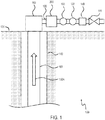
- FIG. 1 illustrates an example of a hydrocarbon production system 100.
- the production system 100 can include a hydrocarbon production piping 120 connected to a wellhead 103 above the surface 130.
- the wellhead 103 can be connected to a production casing 101 that extends down a wellbore 140.
- the production casing 101 can isolate a hydrocarbon producing zone of a rock formation from other formations along the wellbore.
- the production system 100 can optionally include additional casings, such as a conductor casing or surface casing.
- the wellhead 103 can serve as a pressure-containing interface between the casing 101 and the production piping 120.
- Well fluid 150A can flow uphole through the casing 101 to the surface 130 and flow through the piping 120 to an end user.
- the well fluid 150A can also carry debris as it flows through the casing 101 and piping 120.
- the production system 100 can include various components along the production piping 120 downstream of the wellhead 103, such as a hydrocarbon production apparatus 200 for removing debris and a control valve 111 for controlling the flow of well fluid 150A.
- the production system 100 can optionally include various process instruments for monitoring and process controlling purposes, such as a pressure instrument 105, a temperature instrument 107, and a flow instrument 109.
- the apparatus 200 also referred to as a debris removing apparatus and described in more detail later, in operation, reduces the amount of debris flowing with the well fluid 150A by diverting a portion of the debris away from the main flow of well fluid 150A.
- the apparatus 200 can be positioned along the production piping 120 directly downstream of the wellhead 103 and upstream of any instruments or equipment, such as the control valve 111 and its associated instruments (105, 107, 109), so that debris can be removed from the well fluid 150A before reaching the downstream instrument and equipment.
- the debris removing apparatus 200 can include a first conduit 201, a second conduit 203, a valve 215, and a baffle 207A.
- the first conduit 201 and the second conduit 203 can be made of the same material as the production piping 120 or another material, such as stainless steel suitable for sour service (that is, hydrogen sulfide service).
- the first conduit 201 has an inlet 211A and an outlet 211B, with a flow path that extends between the inlet 211A and the outlet 211B to receive a flow of a hydrocarbon fluid from the inlet 211A and direct the hydrocarbon fluid from the inlet 211A to the outlet 211B.
- the hydrocarbon fluid can include debris and can be, for example, the debris-carrying well fluid 150A.
- the inlet 211A and outlet 211B are connected to the production piping 120.
- the second conduit 203 can be angularly connected to the first conduit 201 between the inlet 211A and the outlet 211B.
- the first conduit 201 can have a diameter that is approximately equal to the diameter of the production piping 120. In the case that the first conduit 201 and the piping 120 have approximately the same diameter, the first conduit 201 and the piping 120 would also have approximately the same cross-sectional area, resulting in the well fluid 150A flowing through the apparatus 200 at approximately the same velocity.
- “approximately” means a deviation or allowance of up to 10 percent (%) and any variation from a mentioned value is within the tolerance limits of any machinery used to manufacture the part.
- the diameter of the first conduit 201 is smaller than the diameter of the piping 120. In other implementations, in order to have a velocity of the debris-carrying well fluid 150A flowing through the apparatus 200 lower than the velocity through the piping 120, the diameter of the first conduit 201 is larger than the diameter of the piping 120.
- the second conduit 203 includes a debris receptacle 205.
- the receptacle 205 can include a pressure instrument 219 and a bleed valve 217 that can open to relieve a fluid from the receptacle 205.
- the receptacle 205 can be made of the same material as the second conduit 203 or another material.
- the receptacle 205 can have any shape, such as cylindrical or cuboidal.
- the size of the receptacle 205 can be determined based on size constraints, for example, the available space at the site below the production piping 120. A larger receptacle 205 can potentially result in the need to service the apparatus 200 less often due to its capacity to hold a larger amount of debris before needing to be emptied.
- the receptacle 205 can optionally include an optically transparent window (not shown) to allow observation of debris accumulation within the receptacle 205.
- the second conduit 203 is connected to the first conduit 201, such that a longitudinal axis of the first conduit 201 and a longitudinal axis of the second conduit 203 intersect perpendicularly (that is, at an angle of 90 degrees), as shown on FIG. 2 .
- the longitudinal axis of the first conduit 201 and the longitudinal axis of the second conduit 203 intersect at an angle less than 90 degrees.
- the valve 215 is fluidly coupled to the second conduit 203 and can isolate the debris receptacle 205 from the flow path of the first conduit 201 and at least a portion of the second conduit 203.
- the valve 215 is an isolation valve that has an inlet 213A and an outlet 213B, and the receptacle 205 is connected to the valve outlet 213B.
- the baffle 207A (also referred to as the first baffle) is coupled to a portion of the inner surface of the first conduit 201 between the inlet 211A and the outlet 211B, for example, the bottom portion, and can be oriented to direct at least a portion of the debris from the flow path of the first conduit 201 to the second conduit 203.
- the baffle 207A can be coupled to the first conduit 201 at an angle of 90 degrees or less, such as 45 degrees.
- the perpendicular distance 210A between the tip of the baffle 207A and the inner surface of the first conduit 201 can be approximately equal to or longer than half of the diameter of the first conduit 201. With respect to the hydrocarbon production system 100 (referring back to FIG. 1 ), in certain implementations, the distance 210A can be approximately equal to or longer than the diameter of the flow area of the control valve 111 when the valve 111 is fully open (that is, at 100% travel).
- the debris removing apparatus 200 can include an additional baffle, such as baffle 207B (also referred to as the second baffle), which can be coupled to another portion of the inner surface of the first conduit 201 between the inlet 211A and the outlet 211B, for example, the top portion.
- the second baffle 207B can have similar characteristics as the first baffle 207A.
- the second baffle 207B can also be oriented to direct a portion of the debris from the flow path of the first conduit 201 to the second conduit 203.
- the second baffle 207B can also be coupled to the first conduit 201 at an angle of 90 degrees or less.
- the perpendicular distance 210B between the tip of the second baffle 207B and the inner surface of the first conduit 201 can also be approximately equal to or longer than half of the diameter of the first conduit 201.
- the axial distance 208 between the tip of the first baffle 207A and the tip of the second baffle 207B can be approximately equal to or longer than half of the diameter of the first conduit 201.
- the distance 210B can be approximately equal to or longer than the diameter of the flow area of the control valve 111 when the valve 111 is fully open (that is, at 100% travel).
- the axial distance 208 can be approximately equal to or longer than the diameter of the flow area of the control valve 111 when the valve 111 is fully open (that is, at 100% travel).
- the distances 210A, 210B, and 208 are approximately equal to or longer than the diameter of the smallest flow area of any downstream instruments and pieces of equipment (not shown) along the production piping 120.
- the apparatus 200 can optionally include additional baffles.
- the baffles (such as 207A and 207B) can be made of the same material as the first conduit 201 or a higher strength material, such as polycrystalline diamond compact (PDC), which is abrasion-resistant and corrosion-resistant.
- PDC polycrystalline diamond compact
- the apparatus 200 receives at its inlet 211A, debris-carrying well fluid 150A from the production piping 120.
- debris can come in contact with at least one baffle (such as baffles 207A and 207B) and be directed to the second conduit 203.
- the debris can flow through the second conduit 203 and can settle and accumulate within the receptacle 205, as well fluid continues to flow through the first conduit 201.
- Some debris can travel past the baffles of the first conduit 201.
- a portion of the debris carried by well fluid 150A can flow through the first conduit 201 without coming in contact with the baffles.
- Downstream of the baffles (for example, 207A and 207B), the well fluid 150B can carry a smaller amount of debris.
- the well fluid 150B with less debris flows out of the apparatus 200 through its outlet 211B, and continues to flow through the production piping 120.
- FIG. 3 illustrates a simplified view of a section of a hydrocarbon production system, such as the system 100 shown in FIG. 1 .
- Auxiliary components such as pressure or flow instruments can be included but are not shown in FIG. 3 .
- Well fluid 150A can carry debris as it flows through the production piping 120.
- a debris removing apparatus such as the apparatus 200 shown in FIG. 2 , is positioned upstream of a valve, such as the control valve 111 shown in FIG. 1 .
- the apparatus 200 can direct a portion of the debris carried by the well fluid 150A to the receptacle 205.
- the well fluid 150B exiting the apparatus 200 can carry less debris than the well fluid 150A entering the apparatus 200. Because the apparatus 200 is located upstream of the control valve 111 and can remove debris before the debris reaches the valve 111, the likelihood of debris plugging or damaging the valve 111 can be reduced.
- debris can accumulate within the receptacle 205 of the debris removing apparatus 200. After some period of operation, the receptacle 205 may be emptied.
- the valve 215 can be closed to isolate the receptacle 205 from the rest of the apparatus 200 and main flow of well fluid 150A, so that the receptacle 205 can be emptied while production continues.
- the production system 100 can include additional debris removing apparatuses (such as the apparatus 200) in series.
- the multiple apparatuses can be the same, or each apparatus can have different dimensions and be designed to remove varying target sizes of debris from the well fluid 150A.
- the production system 100 can include additional debris removing apparatuses (such as the apparatus 200) in parallel.
- the production piping 120 can be split into multiple, smaller pipes.
- the production system 100 can include multiple debris removing apparatuses in a combination of series and parallel configurations. The configuration can be chosen based on size constraints while also taking into consideration pressure drop of the well fluid as the well fluid flows through the apparatus.
- FIG. 4 is a flow chart of a method 400 for removing debris from a hydrocarbon fluid flow stream.
- the method 400 starts at 401 by receiving a flow of a hydrocarbon fluid including debris, such as well fluid 150A, into an inlet of a first conduit, such as the conduit 201 of apparatus 200 shown in FIG. 2 .
- the fluid can come from a production piping, such as piping 120, and the first conduit can be connected to the piping.
- the first conduit includes a flow path that extends between the inlet (for example, inlet 211A) and an outlet (for example, outlet 211B) of the first conduit.
- method 400 proceeds to 403, where at least a portion of the debris from the hydrocarbon fluid is separated with at least one baffle (such as baffle 207A) that is coupled to a portion of an inner surface of the first conduit between the inlet and the outlet.
- the debris can be separated with additional baffles (such as baffle 207B).
- the portion of separated debris is directed into a debris receptacle (such as receptacle 205) of a second conduit (such as conduit 203) that is angularly connected to the first conduit between the inlet and the outlet.
- a debris receptacle such as receptacle 205
- a second conduit such as conduit 203
- Each baffle can be oriented to direct a portion of the debris from the flow path of the first conduit to the second conduit, which includes the receptacle.
- the second conduit is connected to the first conduit such that a longitudinal axis of the first conduit and a longitudinal axis of the second conduit intersect at an angle of 90 degrees (that is, perpendicularly) or less.
- method 400 proceeds to 407, where the debris receptacle is fluidly isolated from the flow path of the first conduit and at least a portion of the second conduit.
- the receptacle can be isolated by closing a valve that is fluidly coupled to the second conduit, such as the valve 215.
- method 400 proceeds to 409, where the portion of separated debris is removed from the debris receptacle.
- Removing the debris from the receptacle can involve bleeding a portion of a fluid from the receptacle (for example, by opening a bleed valve) to reduce pressure within the receptacle and verifying that the pressure within the receptacle is at an acceptable level before disconnecting the receptacle. The debris and remaining portion of fluid within the receptacle can be removed.
- FIG. 5 is a flow chart of a method 500 for servicing a hydrocarbon production apparatus for removing debris from a fluid flow stream, such as the apparatus 200 shown in FIG. 2 .
- the method 500 starts at 501 by closing a valve to isolate a receptacle of the apparatus from the fluid flow stream.
- the receptacle can contain fluid and debris from the fluid flow stream.
- a portion of the fluid is bled from the receptacle to reduce pressure within the receptacle.
- the bleeding can involve opening a bleed valve (such as the valve 217).
- the pressure within the receptacle is verified.
- the pressure can be verified during or after the bleeding step. Once the pressure is verified as being at an acceptable level (for example, close to atmospheric pressure in consideration of safe operation), method 500 proceeds to 507, where the receptacle is disconnected from the apparatus.
- the debris and a remaining portion of the fluid is removed from the receptacle.
- the fluid and debris can be disposed or tested in order to gather information about the reservoir.
- the receptacle is reconnected to the apparatus, and at 513, the valve is opened, so that the receptacle is back in fluid communication with the fluid flow stream and can receive additional debris.
Landscapes
- Chemical & Material Sciences (AREA)
- Engineering & Computer Science (AREA)
- Chemical Kinetics & Catalysis (AREA)
- Oil, Petroleum & Natural Gas (AREA)
- Geology (AREA)
- Mining & Mineral Resources (AREA)
- Life Sciences & Earth Sciences (AREA)
- General Chemical & Material Sciences (AREA)
- Organic Chemistry (AREA)
- Environmental & Geological Engineering (AREA)
- Fluid Mechanics (AREA)
- Physics & Mathematics (AREA)
- General Life Sciences & Earth Sciences (AREA)
- Geochemistry & Mineralogy (AREA)
- Production Of Liquid Hydrocarbon Mixture For Refining Petroleum (AREA)
- Cleaning In General (AREA)
Claims (15)
- Kohlenwasserstofffördervorrichtung (200), wobei die Vorrichtung umfasst:eine erste Leitung (201), die einen Einlass (211A) und einen Auslass (211B) und einen Flussweg, der zwischen dem Einlass und dem Auslass verläuft, umfasst, wobei der Flussweg dafür gestaltet ist, einen Fluss eines Kohlenwasserstofffluids von dem Einlass aufzunehmen und das Kohlenwasserstofffluid von dem Einlass zu dem Auslass zu leiten, wobei das Kohlenwasserstofffluid Fremdkörper umfasst;eine zweite Leitung (203), die abgewinkelt mit der ersten Leitung zwischen dem Einlass und dem Auslass verbunden ist, wobei die zweite Leitung einen Fremdkörper-Sammelbehälter (205) umfasst;ein Ventil (215), das mit der zweiten Leitung fluidgekoppelt ist und dafür gestaltet ist, den Fremdkörper-Sammelbehälter von dem Flussweg der ersten Leitung und wenigstens einem Teil der zweiten Leitung zu trennen; und dadurch gekennzeichnet, dass die Kohlenwasserstofffördervorrichtung ferner umfasst:wenigstens ein Leitblech (207A), das an einen Teil einer Innenfläche der ersten Leitung zwischen dem Einlass und dem Auslass gekoppelt ist, wobei das wenigstens eine Leitblech ausgerichtet ist, wenigstens einen Teil der Fremdkörper aus dem Flussweg der ersten Leitung in die zweite Leitung zu lenken.
- Vorrichtung gemäß Anspruch 1, wobei die zweite Leitung so mit der ersten Leitung verbunden ist, dass sich die Längsachse der ersten Leitung und die Längsachse der zweiten Leitung in einem Winkel von 90 Grad oder weniger schneiden.
- Vorrichtung gemäß Anspruch 1, wobei das Ventil ein Trennventil, einen Einlass (213A) und einen Auslass (213B) umfasst, wobei der Sammelbehälter mit dem Auslass des Ventils verbunden ist.
- Vorrichtung gemäß Anspruch 1, wobei das wenigstens eine Leitblech in einem Winkel von 90 Grad oder weniger an die Innenfläche der ersten Leitung gekoppelt ist und wobei gegebenenfalls ein senkrechter Abstand (210A) zwischen einer Spitze des wenigstens einen Leitblechs und der Innenfläche der ersten Leitung etwa den halben Durchmesser der ersten Leitung oder mehr beträgt.
- Vorrichtung gemäß Anspruch 4, wobei das wenigstens eine Leitblech ein erstes Leitblech ist, wobei die Vorrichtung ferner ein zweites Leitblech (207B) umfasst, das an einen zweiten Teil der Innenfläche der ersten Leitung zwischen dem Einlass und dem Auslass gekoppelt ist, wobei das zweite Leitblech ausgerichtet ist, einen Teil der Fremdkörper aus dem Flussweg der ersten Leitung in die zweite Leitung zu lenken, und wobei gegebenenfalls wenigstens eines von:a) einem senkrechten Abstand (210B) zwischen einer Spitze des zweiten Leitblechs und der Innenfläche der ersten Leitung etwa den halben Durchmesser der ersten Leitung oder mehr beträgt;b) einem axialen Abstand (208) zwischen der Spitze des ersten Leitblechs und einer Spitze des zweiten Leitblechs etwa den halben Durchmesser der ersten Leitung oder mehr beträgt; undc) dem zweiten Leitblech in einem Winkel von 90 Grad oder weniger an die Innenfläche der ersten Leitung gekoppelt ist.
- Vorrichtung gemäß Anspruch 1, wobei der Sammelbehälter ein Druckinstrument und ein Ablassventil, das zum Ablassen von Fluid aus dem Sammelbehälter gestaltet ist, umfasst.
- Kohlenwasserstofffördersystem (100), wobei das System umfasst:ein Kohlenwasserstoffförderrohr (120), das zur Verbindung mit einem Bohrlochkopf (103) gestaltet ist; unddie Kohlenwasserstofffördervorrichtung (200) gemäß einem der Ansprüche 1-6, wobei die Vorrichtung in dem Kohlenwasserstoffförderrohr stromabwärts bezogen auf den Bohrlochkopf angeordnet ist.
- System gemäß Anspruch 7, ferner umfassend ein Druckinstrument (105), ein Temperarturinstrument (107), ein Flussinstrument (109) und ein Steuerventil (111), die alle in dem Kohlenwasserstoffförderrohr stromabwärts bezogen auf die Vorrichtung angeordnet sind.
- System gemäß Anspruch 8, wobei ein senkrechter Abstand zwischen einer Spitze des wenigstens einen Leitblechs und einer Innenfläche der ersten Leitung etwa einen Durchmesser des Strömungsquerschnitts des vollständig offenen Steuerventils oder mehr beträgt.
- System gemäß Anspruch 9, wobei das wenigstens eine Leitblech ein erstes Leitblech ist, wobei das System ferner ein zweites Leitblech umfasst, das an einen zweiten Teil der Innenfläche der ersten Leitung gekoppelt ist, wobei das zweite Leitblech ausgerichtet ist, einen Teil der Fremdkörper aus der ersten Leitung in die zweite Leitung zu lenken, und wobei gegebenenfalls wenigstens eines von:a) einem senkrechten Abstand zwischen einer Spitze des zweiten Leitblechs und der Innenfläche der ersten Leitung etwa den Durchmesser des Strömungsquerschnitts des vollständig offenen Steuerventils oder mehr beträgt;b) dem zweiten Leitblech in einem Winkel von 90 Grad oder weniger an die Innenfläche der ersten Leitung gekoppelt ist; undc) einem axialen Abstand zwischen der Spitze des ersten Leitblechs und der Spitze des zweiten Leitblechs etwa den Durchmesser des Strömungsquerschnitts des vollständig offenen Steuerventils oder mehr beträgt.
- System gemäß Anspruch 7, wobei der Sammelbehälter ein Druckinstrument (219) und ein Ablassventil (217), das zum Ablassen von Fluid aus dem Sammelbehälter gestaltet ist, umfasst.
- Verfahren zum Entfernen von Fremdkörpern aus einem Kohlenwasserstofffluid-Flussstrom, umfassend:Aufnehmen eines Flusses eines Kohlenwasserstofffluids (150A), das Fremdkörper umfasst, in einen Einlass (211A) einer ersten Leitung (201), die einen Flussweg umfasst, der zwischen dem Einlass und einem Auslass (211B) der ersten Leitung verläuft;Abtrennen wenigstens eines Teils der Fremdkörper aus dem Kohlenwasserstofffluid mit wenigstens einem Leitblech (207A), das an einen Teil einer Innenfläche der ersten Leitung zwischen dem Einlass und dem Auslass gekoppelt ist;Leiten des Teils von abgetrennten Fremdkörpern in einen Fremdkörper-Sammelbehälter (205) einer zweiten Leitung (203), die abgewinkelt mit der ersten Leitung zwischen dem Einlass und dem Auslass verbunden ist;fluidisches Trennen des Fremdkörper-Sammelbehälters von dem Flussweg der ersten Leitung und wenigstens einem Teil der zweiten Leitung; undnach dem fluidischen Trennen des Fremdkörper-Sammelbehälters Entnehmen des Teils der abgetrennten Fremdkörper aus dem Fremdkörper-Sammelbehälter.
- Verfahren gemäß Anspruch 12, wobei Trennen des Fremdkörper-Sammelbehälters Schließen eines mit der zweiten Leitung fluidgekoppelten Ventils (215) umfasst.
- Verfahren gemäß Anspruch 12, wobei Entnehmen der abgetrennten Fremdkörper umfasst:Ablassen eines Teils eines Fluids aus dem Sammelbehälter, um den Druck in dem Sammelbehälter zu verringern;Erfassen des Drucks in dem Sammelbehälter;Trennen des Sammelbehälters; undEntnehmen der abgetrennten Fremdkörper und eines verbleibenden Teils des Fluids aus dem Sammelbehälter,und wobei das Ablassen des Teils des Fluids aus dem Sammelbehälter gegebenenfalls Öffnen eines Ablassventils (217) umfasst.
- Verfahren gemäß Anspruch 14, ferner umfassend:Wiederverbinden des Sammelbehälters mit der Vorrichtung; undÖffnen des Ventils.
Applications Claiming Priority (2)
| Application Number | Priority Date | Filing Date | Title |
|---|---|---|---|
| US15/688,328 US10625181B2 (en) | 2017-08-28 | 2017-08-28 | Removing debris from a hydrocarbon fluid |
| PCT/US2018/048054 WO2019046146A1 (en) | 2017-08-28 | 2018-08-27 | REMOVAL OF DEBRIS FROM A HYDROCARBON FLUID |
Publications (2)
| Publication Number | Publication Date |
|---|---|
| EP3676478A1 EP3676478A1 (de) | 2020-07-08 |
| EP3676478B1 true EP3676478B1 (de) | 2021-08-11 |
Family
ID=63528917
Family Applications (1)
| Application Number | Title | Priority Date | Filing Date |
|---|---|---|---|
| EP18766451.1A Active EP3676478B1 (de) | 2017-08-28 | 2018-08-27 | Entfernung von rückständen aus einer kohlenwasserstoffflüssigkeit |
Country Status (4)
| Country | Link |
|---|---|
| US (2) | US10625181B2 (de) |
| EP (1) | EP3676478B1 (de) |
| SA (1) | SA520411447B1 (de) |
| WO (1) | WO2019046146A1 (de) |
Families Citing this family (4)
| Publication number | Priority date | Publication date | Assignee | Title |
|---|---|---|---|---|
| US10905975B2 (en) * | 2018-11-15 | 2021-02-02 | Saudi Arabian Oil Company | Removable trap stations for hydrocarbon flowlines |
| US11555571B2 (en) | 2020-02-12 | 2023-01-17 | Saudi Arabian Oil Company | Automated flowline leak sealing system and method |
| US11560326B2 (en) * | 2021-03-08 | 2023-01-24 | Synergy Watercare Solutions Inc. | Fluid treatment system and process |
| US11867012B2 (en) | 2021-12-06 | 2024-01-09 | Saudi Arabian Oil Company | Gauge cutter and sampler apparatus |
Family Cites Families (13)
| Publication number | Priority date | Publication date | Assignee | Title |
|---|---|---|---|---|
| US381374A (en) | 1888-04-17 | Separator | ||
| US774519A (en) | 1903-05-23 | 1904-11-08 | Greenaway Company | Separator. |
| US4106562A (en) | 1977-05-16 | 1978-08-15 | Union Oil Company Of California | Wellhead apparatus |
| US5394339A (en) * | 1992-03-30 | 1995-02-28 | Paul-Munroe Hydraulics Inc. | Apparatus for analyzing oil well production fluid |
| US6032539A (en) * | 1996-10-11 | 2000-03-07 | Accuflow, Inc. | Multiphase flow measurement method and apparatus |
| FR2761109B1 (fr) | 1997-03-18 | 1999-06-11 | Total Sa | Dispositif destine a equiper la tete d'un puits de production d'un fluide, en vue de retenir les particules solides entrainees par ce fluide |
| WO2001079657A1 (en) | 2000-04-12 | 2001-10-25 | Wood Group Pressure Control Limited | Debris catcher |
| US6419730B1 (en) | 2000-08-28 | 2002-07-16 | Felix Chavez | Gas transmission system including a water separator |
| US6766856B1 (en) | 2002-01-28 | 2004-07-27 | Schooner Petroleum Services, Inc. | Large particulate removal system |
| US7735548B2 (en) | 2007-06-25 | 2010-06-15 | Isolation Equipment Services Inc | Ball catcher for wellbore operations |
| US8454843B2 (en) | 2010-05-03 | 2013-06-04 | Petroleos De Venezuela, S.A. | Production fluid solid trap |
| US9114332B1 (en) * | 2012-07-23 | 2015-08-25 | Herbert Liu | Multiphase flow measurement apparatus utilizing phase separation |
| US9095799B1 (en) | 2013-03-12 | 2015-08-04 | John Henry Packard | Debris catcher and sand trap for pipeline |
-
2017
- 2017-08-28 US US15/688,328 patent/US10625181B2/en active Active
-
2018
- 2018-08-27 WO PCT/US2018/048054 patent/WO2019046146A1/en unknown
- 2018-08-27 EP EP18766451.1A patent/EP3676478B1/de active Active
-
2020
- 2020-02-29 SA SA520411447A patent/SA520411447B1/ar unknown
- 2020-04-07 US US16/842,405 patent/US11242738B2/en active Active
Also Published As
| Publication number | Publication date |
|---|---|
| US20190060795A1 (en) | 2019-02-28 |
| US10625181B2 (en) | 2020-04-21 |
| US11242738B2 (en) | 2022-02-08 |
| WO2019046146A1 (en) | 2019-03-07 |
| EP3676478A1 (de) | 2020-07-08 |
| US20200230524A1 (en) | 2020-07-23 |
| SA520411447B1 (ar) | 2022-12-18 |
Similar Documents
| Publication | Publication Date | Title |
|---|---|---|
| EP3676478B1 (de) | Entfernung von rückständen aus einer kohlenwasserstoffflüssigkeit | |
| US10995600B2 (en) | Gas separator | |
| CA2856689C (en) | Apparatus and method for removing debris from a well | |
| CA2635852C (en) | Ball catcher for wellbore operations | |
| US10871062B2 (en) | Skid mounted wellhead desanders and flowback systems | |
| US6129150A (en) | Method and equipment for offshore oil production by intermittent gas injection | |
| EP2009226B1 (de) | Vorrichtung und Verfahren zum Abdichten eines Ringraumes | |
| CN104514503A (zh) | 岩屑过滤装置 | |
| US9580995B2 (en) | Controlled pressure equalization | |
| US9228409B2 (en) | System, apparatus and process for collecting balls from wellbore fluids containing sand | |
| WO2009058398A1 (en) | Flow back separators | |
| US10583373B2 (en) | Method and device for separation of liquids and gas with use of inclined and rounded holes or channels in the wall of a pipe | |
| CA2876608A1 (en) | Apparatus for ball catching | |
| CA2716039C (en) | System, apparatus and process for collecting balls from wellbore fluids containing sand | |
| CA2876603A1 (en) | Apparatus for ball catching | |
| KR102263165B1 (ko) | 해양플랜트의 유체 흐름 제어 시스템 | |
| CN115875020A (zh) | 一种返排测试系统及方法 | |
| CA2876453A1 (en) | Apparatus for ball catching | |
| CN203547604U (zh) | 岩屑过滤装置 | |
| CA2867083A1 (en) | Ball catcher | |
| US20180038181A1 (en) | Valve assembly with a filter chamber |
Legal Events
| Date | Code | Title | Description |
|---|---|---|---|
| STAA | Information on the status of an ep patent application or granted ep patent |
Free format text: STATUS: UNKNOWN |
|
| STAA | Information on the status of an ep patent application or granted ep patent |
Free format text: STATUS: THE INTERNATIONAL PUBLICATION HAS BEEN MADE |
|
| PUAI | Public reference made under article 153(3) epc to a published international application that has entered the european phase |
Free format text: ORIGINAL CODE: 0009012 |
|
| STAA | Information on the status of an ep patent application or granted ep patent |
Free format text: STATUS: REQUEST FOR EXAMINATION WAS MADE |
|
| 17P | Request for examination filed |
Effective date: 20200312 |
|
| AK | Designated contracting states |
Kind code of ref document: A1 Designated state(s): AL AT BE BG CH CY CZ DE DK EE ES FI FR GB GR HR HU IE IS IT LI LT LU LV MC MK MT NL NO PL PT RO RS SE SI SK SM TR |
|
| AX | Request for extension of the european patent |
Extension state: BA ME |
|
| DAV | Request for validation of the european patent (deleted) | ||
| DAX | Request for extension of the european patent (deleted) | ||
| REG | Reference to a national code |
Ref country code: DE Ref legal event code: R079 Ref document number: 602018021745 Country of ref document: DE Free format text: PREVIOUS MAIN CLASS: E21B0043340000 Ipc: C10G0031000000 |
|
| GRAP | Despatch of communication of intention to grant a patent |
Free format text: ORIGINAL CODE: EPIDOSNIGR1 |
|
| STAA | Information on the status of an ep patent application or granted ep patent |
Free format text: STATUS: GRANT OF PATENT IS INTENDED |
|
| RIC1 | Information provided on ipc code assigned before grant |
Ipc: E21B 43/34 20060101ALI20210212BHEP Ipc: C10G 31/00 20060101AFI20210212BHEP Ipc: B01D 45/08 20060101ALI20210212BHEP |
|
| INTG | Intention to grant announced |
Effective date: 20210324 |
|
| GRAS | Grant fee paid |
Free format text: ORIGINAL CODE: EPIDOSNIGR3 |
|
| GRAA | (expected) grant |
Free format text: ORIGINAL CODE: 0009210 |
|
| STAA | Information on the status of an ep patent application or granted ep patent |
Free format text: STATUS: THE PATENT HAS BEEN GRANTED |
|
| AK | Designated contracting states |
Kind code of ref document: B1 Designated state(s): AL AT BE BG CH CY CZ DE DK EE ES FI FR GB GR HR HU IE IS IT LI LT LU LV MC MK MT NL NO PL PT RO RS SE SI SK SM TR |
|
| REG | Reference to a national code |
Ref country code: CH Ref legal event code: EP |
|
| REG | Reference to a national code |
Ref country code: DE Ref legal event code: R096 Ref document number: 602018021745 Country of ref document: DE |
|
| REG | Reference to a national code |
Ref country code: IE Ref legal event code: FG4D Ref country code: AT Ref legal event code: REF Ref document number: 1419385 Country of ref document: AT Kind code of ref document: T Effective date: 20210915 |
|
| REG | Reference to a national code |
Ref country code: LT Ref legal event code: MG9D |
|
| REG | Reference to a national code |
Ref country code: NL Ref legal event code: MP Effective date: 20210811 |
|
| REG | Reference to a national code |
Ref country code: AT Ref legal event code: MK05 Ref document number: 1419385 Country of ref document: AT Kind code of ref document: T Effective date: 20210811 |
|
| PG25 | Lapsed in a contracting state [announced via postgrant information from national office to epo] |
Ref country code: PT Free format text: LAPSE BECAUSE OF FAILURE TO SUBMIT A TRANSLATION OF THE DESCRIPTION OR TO PAY THE FEE WITHIN THE PRESCRIBED TIME-LIMIT Effective date: 20211213 Ref country code: NO Free format text: LAPSE BECAUSE OF FAILURE TO SUBMIT A TRANSLATION OF THE DESCRIPTION OR TO PAY THE FEE WITHIN THE PRESCRIBED TIME-LIMIT Effective date: 20211111 Ref country code: AT Free format text: LAPSE BECAUSE OF FAILURE TO SUBMIT A TRANSLATION OF THE DESCRIPTION OR TO PAY THE FEE WITHIN THE PRESCRIBED TIME-LIMIT Effective date: 20210811 Ref country code: BG Free format text: LAPSE BECAUSE OF FAILURE TO SUBMIT A TRANSLATION OF THE DESCRIPTION OR TO PAY THE FEE WITHIN THE PRESCRIBED TIME-LIMIT Effective date: 20211111 Ref country code: LT Free format text: LAPSE BECAUSE OF FAILURE TO SUBMIT A TRANSLATION OF THE DESCRIPTION OR TO PAY THE FEE WITHIN THE PRESCRIBED TIME-LIMIT Effective date: 20210811 Ref country code: RS Free format text: LAPSE BECAUSE OF FAILURE TO SUBMIT A TRANSLATION OF THE DESCRIPTION OR TO PAY THE FEE WITHIN THE PRESCRIBED TIME-LIMIT Effective date: 20210811 Ref country code: SE Free format text: LAPSE BECAUSE OF FAILURE TO SUBMIT A TRANSLATION OF THE DESCRIPTION OR TO PAY THE FEE WITHIN THE PRESCRIBED TIME-LIMIT Effective date: 20210811 Ref country code: ES Free format text: LAPSE BECAUSE OF FAILURE TO SUBMIT A TRANSLATION OF THE DESCRIPTION OR TO PAY THE FEE WITHIN THE PRESCRIBED TIME-LIMIT Effective date: 20210811 Ref country code: FI Free format text: LAPSE BECAUSE OF FAILURE TO SUBMIT A TRANSLATION OF THE DESCRIPTION OR TO PAY THE FEE WITHIN THE PRESCRIBED TIME-LIMIT Effective date: 20210811 Ref country code: HR Free format text: LAPSE BECAUSE OF FAILURE TO SUBMIT A TRANSLATION OF THE DESCRIPTION OR TO PAY THE FEE WITHIN THE PRESCRIBED TIME-LIMIT Effective date: 20210811 |
|
| PG25 | Lapsed in a contracting state [announced via postgrant information from national office to epo] |
Ref country code: PL Free format text: LAPSE BECAUSE OF FAILURE TO SUBMIT A TRANSLATION OF THE DESCRIPTION OR TO PAY THE FEE WITHIN THE PRESCRIBED TIME-LIMIT Effective date: 20210811 Ref country code: LV Free format text: LAPSE BECAUSE OF FAILURE TO SUBMIT A TRANSLATION OF THE DESCRIPTION OR TO PAY THE FEE WITHIN THE PRESCRIBED TIME-LIMIT Effective date: 20210811 Ref country code: GR Free format text: LAPSE BECAUSE OF FAILURE TO SUBMIT A TRANSLATION OF THE DESCRIPTION OR TO PAY THE FEE WITHIN THE PRESCRIBED TIME-LIMIT Effective date: 20211112 |
|
| REG | Reference to a national code |
Ref country code: DE Ref legal event code: R119 Ref document number: 602018021745 Country of ref document: DE |
|
| REG | Reference to a national code |
Ref country code: CH Ref legal event code: PL |
|
| PG25 | Lapsed in a contracting state [announced via postgrant information from national office to epo] |
Ref country code: NL Free format text: LAPSE BECAUSE OF FAILURE TO SUBMIT A TRANSLATION OF THE DESCRIPTION OR TO PAY THE FEE WITHIN THE PRESCRIBED TIME-LIMIT Effective date: 20210811 |
|
| REG | Reference to a national code |
Ref country code: BE Ref legal event code: MM Effective date: 20210831 |
|
| PG25 | Lapsed in a contracting state [announced via postgrant information from national office to epo] |
Ref country code: LI Free format text: LAPSE BECAUSE OF NON-PAYMENT OF DUE FEES Effective date: 20210831 Ref country code: DK Free format text: LAPSE BECAUSE OF FAILURE TO SUBMIT A TRANSLATION OF THE DESCRIPTION OR TO PAY THE FEE WITHIN THE PRESCRIBED TIME-LIMIT Effective date: 20210811 Ref country code: CH Free format text: LAPSE BECAUSE OF NON-PAYMENT OF DUE FEES Effective date: 20210831 |
|
| PG25 | Lapsed in a contracting state [announced via postgrant information from national office to epo] |
Ref country code: SM Free format text: LAPSE BECAUSE OF FAILURE TO SUBMIT A TRANSLATION OF THE DESCRIPTION OR TO PAY THE FEE WITHIN THE PRESCRIBED TIME-LIMIT Effective date: 20210811 Ref country code: SK Free format text: LAPSE BECAUSE OF FAILURE TO SUBMIT A TRANSLATION OF THE DESCRIPTION OR TO PAY THE FEE WITHIN THE PRESCRIBED TIME-LIMIT Effective date: 20210811 Ref country code: RO Free format text: LAPSE BECAUSE OF FAILURE TO SUBMIT A TRANSLATION OF THE DESCRIPTION OR TO PAY THE FEE WITHIN THE PRESCRIBED TIME-LIMIT Effective date: 20210811 Ref country code: MC Free format text: LAPSE BECAUSE OF FAILURE TO SUBMIT A TRANSLATION OF THE DESCRIPTION OR TO PAY THE FEE WITHIN THE PRESCRIBED TIME-LIMIT Effective date: 20210811 Ref country code: LU Free format text: LAPSE BECAUSE OF NON-PAYMENT OF DUE FEES Effective date: 20210827 Ref country code: EE Free format text: LAPSE BECAUSE OF FAILURE TO SUBMIT A TRANSLATION OF THE DESCRIPTION OR TO PAY THE FEE WITHIN THE PRESCRIBED TIME-LIMIT Effective date: 20210811 Ref country code: CZ Free format text: LAPSE BECAUSE OF FAILURE TO SUBMIT A TRANSLATION OF THE DESCRIPTION OR TO PAY THE FEE WITHIN THE PRESCRIBED TIME-LIMIT Effective date: 20210811 Ref country code: AL Free format text: LAPSE BECAUSE OF FAILURE TO SUBMIT A TRANSLATION OF THE DESCRIPTION OR TO PAY THE FEE WITHIN THE PRESCRIBED TIME-LIMIT Effective date: 20210811 |
|
| PLBE | No opposition filed within time limit |
Free format text: ORIGINAL CODE: 0009261 |
|
| STAA | Information on the status of an ep patent application or granted ep patent |
Free format text: STATUS: NO OPPOSITION FILED WITHIN TIME LIMIT |
|
| 26N | No opposition filed |
Effective date: 20220512 |
|
| PG25 | Lapsed in a contracting state [announced via postgrant information from national office to epo] |
Ref country code: IT Free format text: LAPSE BECAUSE OF FAILURE TO SUBMIT A TRANSLATION OF THE DESCRIPTION OR TO PAY THE FEE WITHIN THE PRESCRIBED TIME-LIMIT Effective date: 20210811 Ref country code: IE Free format text: LAPSE BECAUSE OF NON-PAYMENT OF DUE FEES Effective date: 20210827 Ref country code: DE Free format text: LAPSE BECAUSE OF NON-PAYMENT OF DUE FEES Effective date: 20220301 Ref country code: BE Free format text: LAPSE BECAUSE OF NON-PAYMENT OF DUE FEES Effective date: 20210831 |
|
| PG25 | Lapsed in a contracting state [announced via postgrant information from national office to epo] |
Ref country code: SI Free format text: LAPSE BECAUSE OF FAILURE TO SUBMIT A TRANSLATION OF THE DESCRIPTION OR TO PAY THE FEE WITHIN THE PRESCRIBED TIME-LIMIT Effective date: 20210811 |
|
| PG25 | Lapsed in a contracting state [announced via postgrant information from national office to epo] |
Ref country code: FR Free format text: LAPSE BECAUSE OF NON-PAYMENT OF DUE FEES Effective date: 20211011 |
|
| GBPC | Gb: european patent ceased through non-payment of renewal fee |
Effective date: 20220827 |
|
| PG25 | Lapsed in a contracting state [announced via postgrant information from national office to epo] |
Ref country code: CY Free format text: LAPSE BECAUSE OF FAILURE TO SUBMIT A TRANSLATION OF THE DESCRIPTION OR TO PAY THE FEE WITHIN THE PRESCRIBED TIME-LIMIT Effective date: 20210811 |
|
| PG25 | Lapsed in a contracting state [announced via postgrant information from national office to epo] |
Ref country code: HU Free format text: LAPSE BECAUSE OF FAILURE TO SUBMIT A TRANSLATION OF THE DESCRIPTION OR TO PAY THE FEE WITHIN THE PRESCRIBED TIME-LIMIT; INVALID AB INITIO Effective date: 20180827 |
|
| PG25 | Lapsed in a contracting state [announced via postgrant information from national office to epo] |
Ref country code: GB Free format text: LAPSE BECAUSE OF NON-PAYMENT OF DUE FEES Effective date: 20220827 |
|
| PG25 | Lapsed in a contracting state [announced via postgrant information from national office to epo] |
Ref country code: MK Free format text: LAPSE BECAUSE OF FAILURE TO SUBMIT A TRANSLATION OF THE DESCRIPTION OR TO PAY THE FEE WITHIN THE PRESCRIBED TIME-LIMIT Effective date: 20210811 |
|
| PG25 | Lapsed in a contracting state [announced via postgrant information from national office to epo] |
Ref country code: TR Free format text: LAPSE BECAUSE OF FAILURE TO SUBMIT A TRANSLATION OF THE DESCRIPTION OR TO PAY THE FEE WITHIN THE PRESCRIBED TIME-LIMIT Effective date: 20210811 |