EP3676121B1 - Adjustment device for an air influencing element, method for adjusting an air influencing element with an adjustment device, motor vehicle provided with an air influencing element with an adjustment device - Google Patents
Adjustment device for an air influencing element, method for adjusting an air influencing element with an adjustment device, motor vehicle provided with an air influencing element with an adjustment device Download PDFInfo
- Publication number
- EP3676121B1 EP3676121B1 EP18766392.7A EP18766392A EP3676121B1 EP 3676121 B1 EP3676121 B1 EP 3676121B1 EP 18766392 A EP18766392 A EP 18766392A EP 3676121 B1 EP3676121 B1 EP 3676121B1
- Authority
- EP
- European Patent Office
- Prior art keywords
- driving unit
- gear
- adjustment device
- failsafe
- failsafe mechanism
- Prior art date
- Legal status (The legal status is an assumption and is not a legal conclusion. Google has not performed a legal analysis and makes no representation as to the accuracy of the status listed.)
- Active
Links
Images






Classifications
-
- B—PERFORMING OPERATIONS; TRANSPORTING
- B60—VEHICLES IN GENERAL
- B60K—ARRANGEMENT OR MOUNTING OF PROPULSION UNITS OR OF TRANSMISSIONS IN VEHICLES; ARRANGEMENT OR MOUNTING OF PLURAL DIVERSE PRIME-MOVERS IN VEHICLES; AUXILIARY DRIVES FOR VEHICLES; INSTRUMENTATION OR DASHBOARDS FOR VEHICLES; ARRANGEMENTS IN CONNECTION WITH COOLING, AIR INTAKE, GAS EXHAUST OR FUEL SUPPLY OF PROPULSION UNITS IN VEHICLES
- B60K11/00—Arrangement in connection with cooling of propulsion units
- B60K11/08—Air inlets for cooling; Shutters or blinds therefor
- B60K11/085—Air inlets for cooling; Shutters or blinds therefor with adjustable shutters or blinds
-
- B—PERFORMING OPERATIONS; TRANSPORTING
- B62—LAND VEHICLES FOR TRAVELLING OTHERWISE THAN ON RAILS
- B62D—MOTOR VEHICLES; TRAILERS
- B62D35/00—Vehicle bodies characterised by streamlining
-
- F—MECHANICAL ENGINEERING; LIGHTING; HEATING; WEAPONS; BLASTING
- F16—ENGINEERING ELEMENTS AND UNITS; GENERAL MEASURES FOR PRODUCING AND MAINTAINING EFFECTIVE FUNCTIONING OF MACHINES OR INSTALLATIONS; THERMAL INSULATION IN GENERAL
- F16H—GEARING
- F16H1/00—Toothed gearings for conveying rotary motion
- F16H1/02—Toothed gearings for conveying rotary motion without gears having orbital motion
- F16H1/20—Toothed gearings for conveying rotary motion without gears having orbital motion involving more than two intermeshing members
- F16H1/206—Toothed gearings for conveying rotary motion without gears having orbital motion involving more than two intermeshing members characterised by the driving or driven member being composed of two or more gear wheels
-
- F—MECHANICAL ENGINEERING; LIGHTING; HEATING; WEAPONS; BLASTING
- F16—ENGINEERING ELEMENTS AND UNITS; GENERAL MEASURES FOR PRODUCING AND MAINTAINING EFFECTIVE FUNCTIONING OF MACHINES OR INSTALLATIONS; THERMAL INSULATION IN GENERAL
- F16H—GEARING
- F16H19/00—Gearings comprising essentially only toothed gears or friction members and not capable of conveying indefinitely-continuing rotary motion
- F16H19/08—Gearings comprising essentially only toothed gears or friction members and not capable of conveying indefinitely-continuing rotary motion for interconverting rotary motion and oscillating motion
-
- F—MECHANICAL ENGINEERING; LIGHTING; HEATING; WEAPONS; BLASTING
- F16—ENGINEERING ELEMENTS AND UNITS; GENERAL MEASURES FOR PRODUCING AND MAINTAINING EFFECTIVE FUNCTIONING OF MACHINES OR INSTALLATIONS; THERMAL INSULATION IN GENERAL
- F16H—GEARING
- F16H37/00—Combinations of mechanical gearings, not provided for in groups F16H1/00 - F16H35/00
- F16H37/02—Combinations of mechanical gearings, not provided for in groups F16H1/00 - F16H35/00 comprising essentially only toothed or friction gearings
- F16H37/021—Combinations of mechanical gearings, not provided for in groups F16H1/00 - F16H35/00 comprising essentially only toothed or friction gearings toothed gearing combined with continuously variable friction gearing
- F16H37/022—Combinations of mechanical gearings, not provided for in groups F16H1/00 - F16H35/00 comprising essentially only toothed or friction gearings toothed gearing combined with continuously variable friction gearing the toothed gearing having orbital motion
-
- F—MECHANICAL ENGINEERING; LIGHTING; HEATING; WEAPONS; BLASTING
- F16—ENGINEERING ELEMENTS AND UNITS; GENERAL MEASURES FOR PRODUCING AND MAINTAINING EFFECTIVE FUNCTIONING OF MACHINES OR INSTALLATIONS; THERMAL INSULATION IN GENERAL
- F16H—GEARING
- F16H37/00—Combinations of mechanical gearings, not provided for in groups F16H1/00 - F16H35/00
- F16H37/02—Combinations of mechanical gearings, not provided for in groups F16H1/00 - F16H35/00 comprising essentially only toothed or friction gearings
- F16H37/04—Combinations of toothed gearings only
- F16H37/041—Combinations of toothed gearings only for conveying rotary motion with constant gear ratio
-
- F—MECHANICAL ENGINEERING; LIGHTING; HEATING; WEAPONS; BLASTING
- F16—ENGINEERING ELEMENTS AND UNITS; GENERAL MEASURES FOR PRODUCING AND MAINTAINING EFFECTIVE FUNCTIONING OF MACHINES OR INSTALLATIONS; THERMAL INSULATION IN GENERAL
- F16H—GEARING
- F16H37/00—Combinations of mechanical gearings, not provided for in groups F16H1/00 - F16H35/00
- F16H37/12—Gearings comprising primarily toothed or friction gearing, links or levers, and cams, or members of at least two of these types
-
- B—PERFORMING OPERATIONS; TRANSPORTING
- B60—VEHICLES IN GENERAL
- B60Y—INDEXING SCHEME RELATING TO ASPECTS CROSS-CUTTING VEHICLE TECHNOLOGY
- B60Y2400/00—Special features of vehicle units
- B60Y2400/42—Clutches or brakes
-
- F—MECHANICAL ENGINEERING; LIGHTING; HEATING; WEAPONS; BLASTING
- F16—ENGINEERING ELEMENTS AND UNITS; GENERAL MEASURES FOR PRODUCING AND MAINTAINING EFFECTIVE FUNCTIONING OF MACHINES OR INSTALLATIONS; THERMAL INSULATION IN GENERAL
- F16H—GEARING
- F16H2702/00—Combinations of two or more transmissions
- F16H2702/02—Mechanical transmissions with planetary gearing combined with one or more other mechanical transmissions
-
- Y—GENERAL TAGGING OF NEW TECHNOLOGICAL DEVELOPMENTS; GENERAL TAGGING OF CROSS-SECTIONAL TECHNOLOGIES SPANNING OVER SEVERAL SECTIONS OF THE IPC; TECHNICAL SUBJECTS COVERED BY FORMER USPC CROSS-REFERENCE ART COLLECTIONS [XRACs] AND DIGESTS
- Y02—TECHNOLOGIES OR APPLICATIONS FOR MITIGATION OR ADAPTATION AGAINST CLIMATE CHANGE
- Y02T—CLIMATE CHANGE MITIGATION TECHNOLOGIES RELATED TO TRANSPORTATION
- Y02T10/00—Road transport of goods or passengers
- Y02T10/80—Technologies aiming to reduce greenhouse gasses emissions common to all road transportation technologies
- Y02T10/82—Elements for improving aerodynamics
-
- Y—GENERAL TAGGING OF NEW TECHNOLOGICAL DEVELOPMENTS; GENERAL TAGGING OF CROSS-SECTIONAL TECHNOLOGIES SPANNING OVER SEVERAL SECTIONS OF THE IPC; TECHNICAL SUBJECTS COVERED BY FORMER USPC CROSS-REFERENCE ART COLLECTIONS [XRACs] AND DIGESTS
- Y02—TECHNOLOGIES OR APPLICATIONS FOR MITIGATION OR ADAPTATION AGAINST CLIMATE CHANGE
- Y02T—CLIMATE CHANGE MITIGATION TECHNOLOGIES RELATED TO TRANSPORTATION
- Y02T10/00—Road transport of goods or passengers
- Y02T10/80—Technologies aiming to reduce greenhouse gasses emissions common to all road transportation technologies
- Y02T10/88—Optimized components or subsystems, e.g. lighting, actively controlled glasses
Definitions
- the invention relates to an adjustment device for adjusting an air influencing element of a motor vehicle.
- An air influencing element can be, for example, an air inlet of a motor vehicle, in particular adjustable strips or flaps of the air inlet.
- An air influencing element can be, for example, a wing which is situated at an outer side of a motor vehicle, or an air dam or spoiler which is situated at an underside of a motor vehicle.
- the air influencing elements also called air guiding elements, guide or manipulate an air stream in and/or around a vehicle.
- an air influencing element such as an air inlet of a motor compartment, adjustable, whereby the air inlet can be adjusted between an open position and a closed position.
- the air inlet may be provided with elements to be adjusted, for example strips or flaps, which can be adjusted, for example pivoted about an upright or lying axis.
- a motor of a motor vehicle has an optimum operating temperature, which is typically higher than the ambient temperature.
- a closed air inlet when the motor is cold is then once again beneficial to fuel consumption.
- the temperature of the motor can fall below the optimum operating temperature, so that fuel consumption may increase.
- Fuel consumption of the motor may also increase at an operating temperature above the optimum operating temperature.
- a motor vehicle may be provided with one or more wings as air influencing elements.
- a wing may be situated, for example, at the back of the vehicle, or at a side or at a front. Particularly at high speeds of the vehicle, a wing can provide for downward force to keep the vehicle stably on the ground. At low speeds, by contrast, a wing generates mainly resistance, which leads to more fuel consumption. It is hence advantageous to make a spoiler adjustable.
- a motor vehicle may be provided with one or more spoilers as air influencing elements.
- a spoiler is intended for disturbing unwanted air streams around the vehicle, so that resistance can diminish.
- a spoiler may be situated at a back, a side, a front or also a bottom of the vehicle. When a spoiler is situated at a front or a bottom, it is also called air dam.
- a spoiler, or air dam is situated at a bottom of the vehicle, and there, by influencing air streams, can thus reduce the development of whirls between the underside of the vehicle and the road, the resistance of the vehicle during driving can diminish, which can lead to less fuel consumption.
- an air dam when an air dam extends at the underside of the vehicle, it is exposed to obstacles that are on the road, such as a speed bump, or loose chippings or grit. This can lead to damage of the air dam. It may hence be advantageous to make an air dam, in particular an air dam at an underside of the vehicle, adjustable.
- the air influencing element is usually coupled to an adjustment device which comprises a driving unit.
- the air influencing element can be adjusted between a first position and a second position.
- the air inlet can be opened again to provide for sufficient cooling.
- a wing or an air dam may be adjusted, for example, between a first position in which they extend substantially along the vehicle and a second position in which they extend from the vehicle at an angle.
- Publication WO 2013/012337 describes an adjustment device with a failsafe provision which comprises a spring which is connected to the output shaft of the adjustment device.
- the spring is retained, against the spring tension, by an arm which is retained under the influence of magnetic force.
- the magnetic force drops out and the arm moves to release the spring. Under the influence of the spring force, the output shaft of the adjustment device is thus adjusted to the open position.
- Publication DE 39 05 717 describes an adjustment device having a first driving motor and a second driving motor both driving motors coupled to the output shaft. In case of failure of one of the driving motors, the other one can take over the functionality of the failed driving motor.
- a disadvantage of the known adjustment device is that it may be relatively voluminous, and does not always fit within the space available in the vehicle. Also, by the use of tolerance-sensitive parts, the reliability of the adjustment device may sometimes leave to be desired. Also, it has appeared that the adjustment device is relatively expensive.
- An object of the invention is to provide an adjustment device that counteracts at least one of the above-mentioned disadvantages.
- it is desired to provide an adjustment device that can be relatively compact and/or inexpensive and/or reliable.
- the invention provides an adjustment device for adjusting an air influencing element of a motor vehicle according to claim 1.
- the second part of the driving unit may be situated around the axis of the output shaft, while, preferably, the output shaft is at a distance from the input shaft, so that the driving unit can be made of relatively compact design. More preferably, the output shaft is approximately parallel to the input shaft, in this way the driving unit can be made of relatively flat design.
- the adjustment device is provided with a failsafe mechanism.
- the failsafe mechanism is activated in the event of a calamity, for example in case of power failure or in case of fire in the motor compartment for an air inlet, or when an air dam or a spoiler contacts an obstacle.
- the failsafe mechanism is configured, in the event of a calamity, to adjust the air influencing element to a predefined position, for example the first position, or the second position.
- the failsafe mechanism is configured to engage the first part of the driving unit.
- the failsafe mechanism in accordance with the invention engages the first part of the driving unit which is positioned around the input shaft.
- the failsafe mechanism can be made of lighter design, since it is not directly subject to the forces acting on the output shaft of the driving unit.
- the second part is coupled to the first part with a transmission ratio, the transmission ratio being chosen such that the forces on the first part of the driving unit are smaller than on the second part, with the output shaft. Due to the failsafe mechanism engaging the first part, the forces that the failsafe mechanism experiences are also smaller, so that the failsafe mechanism can be made of lighter and more compact design.
- the failsafe mechanism can comprise different parts, but engages, in accordance with the invention, the first part of the driving unit.
- Parts or components of the failsafe mechanism may be situated in the first part of the driving unit, around the input shaft, and/or parts or components of the failsafe mechanism may be situated in the second part of the driving unit, around the output shaft, and/or parts or components of the failsafe mechanism may be situated next to the first part and/or the second part of the driving unit.
- an energy element such as a tension spring, which is pretensioned (biased) to the predefined position of the air influencing elements in the case where the failsafe mechanism comes into operation.
- a tension spring or other elastic element, can provide the energy that is needed to adjust the air influencing elements in the event of a calamity to the predefined position, via the driving unit.
- the tension spring may by one end be connectible, detachably or undetachably, with the first part of the driving unit, or with the second part of the driving unit, and by another end be connected with the fixed world.
- the tension spring may be situated in the second part of the driving unit, or in the first part of the driving unit, or may be placed in the driving unit separately from the first part and from the second part.
- the failsafe mechanism itself engages the first part of the driving unit, for example by retaining or blocking an element or component of the first part and releasing this component in case of a calamity. Whereupon, for example, the energy can be released from the tension spring to adjust the output shaft, whether or not via the first part of the driving unit, to the predefined position of the air influencing elements.
- the first part of the driving unit By coupling the second part of the driving unit to the first part of the driving unit with a transmission ratio, the first part of the driving unit, as well as the failsafe mechanism, can be made of lighter design. After all, not the full forces on the output shaft then act on the first part and/or the failsafe mechanism, but only a part of those forces in accordance with the transmission ratio. For example, if the transmission ratio of the coupling between the first part and the second part is one to three, then the first part of the driving unit and/or the failsafe mechanism only experience one-third of the forces on the output shaft. This way, the first part and/or the failsafe mechanism can hence be lighter and cheaper in design. Obviously, other transmission ratios can also be possible.
- the input shaft is connected with a main driving motor and the output shaft is configured to be connectible with the air influencing element.
- the adjustment device can be coupled with the air influencing element in a compact manner.
- the adjustment device may be provided with a housing.
- the main driving motor may be situated in the housing, while the output shaft of the driving unit can extend through the housing, thus being simply couplable with the air influencing element, for example with shutoff elements of the air inlet, with the spoiler or with the air dam.
- the first part of the driving unit comprises a planetary gear system, comprising a sun gear, at least one planet gear, a planet carrier and a ring gear, while the sun gear is connected with the input shaft.
- the second part of the driving unit comprises an output gear which forms the output shaft of the driving unit.
- the output gear of the second part of the driving unit is coupled with a transmission ratio to an output of the planetary gear system, for example the planet carrier.
- the transmission ratio between the first part and the second part can be realized in a simple manner.
- the ring gear of the planetary gear system is preferably detachably connected with the fixed world, for example a housing of the adjustment device.
- the failsafe mechanism when activated, can drive the ring gear as a second input of the planetary gear system.
- the failsafe mechanism is configured to uncouple the ring gear of the planetary gear system from the fixed world, in a failsafe condition, to adjust the output of the second part of the driving unit. In this way, then, via the ring gear, the second part of the driving unit can be driven in a failsafe condition, for example via a coupling gear.
- the coupling gear is preferably positioned rotatably centered around the output gear of the second part of the driving unit and is rotatably coupled with the ring gear of the planetary gear system of the first part of the driving unit, preferably rotatably coupled with an external toothing on the ring gear of the planetary gear system of the first part of the driving unit.
- the coupling gear is advantageously pretensioned (biased) to a predefined position, for example under the influence of an elastic element such as a spring element. By biasing the coupling gear to the predefined position, in the event of a failsafe condition, the output shaft can be adjusted to the predefined position under the influence of the bias.
- the coupling gear is, via the ring gear, detachably connected with the fixed world, for example the housing.
- the failsafe mechanism will break the coupling of the coupling gear with the fixed world, and, via the ring gear and the planetary gear system, the output gear can still be adjusted for adjustment of the air inlet to the predefined position.
- the failsafe mechanism is usually provided with an energy storage element and/or an activation element.
- the activation element can undo the ring gear's rotation-lock with the fixed world.
- the activation element is here implemented as an auxiliary driving motor.
- an auxiliary driving motor By providing an auxiliary driving motor, the relatively expensive and error-sensitive magnetic coupling element of known failsafe mechanisms can be replaced with a cheaper and more reliable auxiliary driving motor.
- the provision of an auxiliary driving motor allows the driving unit to be made of a more compact design, since the auxiliary driving motor can take up less space than the known magnetic coupling element.
- the auxiliary driving motor is separate from the main driving motor, so that upon activation of the failsafe mechanism the drive of the air inlet does not proceed via the main driving motor.
- the auxiliary driving motor drives merely the failsafe mechanism and not the output shaft.
- the auxiliary driving motor adjusts merely the failsafe mechanism, whereby, through adjustment of the failsafe mechanism, an energy element, such as for example a tension spring, releases energy to adjust the output shaft.
- the auxiliary driving motor is configured for merely driving the failsafe mechanism, and is not configured for driving the output shaft. Because of this, the auxiliary driving motor can be relatively light in design.
- the first part of the driving unit can comprise a clutch ring which is axially movable in a direction of the input shaft of the first part of the driving unit and is nonrotatably connected with the fixed world, for example a housing of the adjustment device, and/or the ring gear is detachably coupled with the clutch ring.
- the ring gear can be detachably couplable with the fixed world in a simple manner.
- the clutch ring may be axially movable and thus retain or release the ring gear under the influence of the failsafe mechanism, for example under the influence of the adjustment of a clutch gear.
- the clutch gear is couplable with the clutch ring, while the clutch ring is configured to be pretensioned to a release position, in the event of a failsafe condition, under the influence of an elastic element, and is configured to be held by the auxiliary driving motor, against the force of the pretension (bias), in a blocking position.
- the adjustment device comprises a park mechanism, so that when the vehicle is parked, and hence the electrical current supply to the adjustment device is shut off, not the failsafe mechanism is activated, but the park mechanism is activated.
- the adjustment device provided with the park mechanism the bias of the clutch gear to the release position is lacking.
- the auxiliary driving motor will hence adjust the clutch gear to a blocking position.
- the park mechanism can leave the driving unit stationary, i.e. unchanged.
- the park mechanism can, by discharge of the energy from the energy storage element to the failsafe mechanism, activate the failsafe mechanism.
- a vehicle control unit Prior to parking, usually, a vehicle control unit first receives a park signal indicating that the vehicle is being parked. In the absence of such park signal, then, when for example the current supply drops out, this will be detected as a calamity and the failsafe mechanism will come into operation.
- the invention also relates to an air inlet provided with such an adjustment device, to a vehicle provided with such an air inlet, and to a method for adjusting an air inlet.
- an adjustment device 1 for adjusting an air influencing element of a motor vehicle.
- the air influencing element can be an air inlet of a motor compartment, which is usually provided with shutoff elements, such as strips, which are adjustable between a first position, in which the air inlet is substantially closed, and a second position, in which the air inlet is substantially open.
- the air inlet is not shown here.
- An air influencing element can also be a spoiler or air dam which is situated preferably at a front or a bottom of the vehicle.
- the air dam may be adjustable between a first position, in which it extends substantially along the vehicle and a second position, in which it extends from the vehicle at an angle.
- An air influencing element can also be a wing, which is usually situated at a back or top of the vehicle.
- the wing may be adjustable between a first position, in which it extends substantially along the vehicle and a second position, in which it extends from the vehicle at an angle, or is at a distance from the vehicle.
- the adjustment device 1 is here provided with a housing 2 and a driving unit 3 which is included in the housing 2.
- the housing 2 here comprises two parts, a first housing part 2a in which the driving unit 3 is situated, and a second housing part 2b, which is here implemented as a cover to close off the first housing part 2a.
- the housing 2 is provided with an entry opening 4 through which a connecting element can be inserted to be connectible to the driving unit 3.
- the connecting element can be, for example, a plug of an onboard system, such as a LIN bus system, or other system.
- the connecting element preferably comprises at least one electricity connection to provide electricity to the driving unit.
- the connecting element may additionally also have a control connection to bring a control signal to the driving unit and/or to bring a control signal from the driving unit back to the onboard system, for example to a central onboard control unit.
- the housing 2 is further provided with at least one exit opening 5. Through the output opening 5 can extend an output shaft element 6 of the driving unit 3 to allow it to be further coupled with the air influencing element, for example with strips of the air inlet, with the air dam or with the wing.
- the driving unit 3 comprises a first part 3a provided around an axis of the input shaft, hereinafter also input axis A, and comprises a second part 3b provided around the axis of the output shaft, hereinafter also output axis B.
- the input axis A is at a distance from the output axis B.
- the input axis A is approximately parallel to the output axis B.
- the output shaft element 6 is situated concentrically around the output axis B.
- the output shaft element 6 can extend from an end 6a to the opposite end 6b.
- the output shaft ends 6a, 6b are preferably situated on either side of the housing 2 through openings 5a and 5b respectively in the housing parts 2a, 2b.
- the output shaft element 6 can extend as a hollow shaft element along axis B.
- the first part 3a is coupled to the second part 3b by a gear coupling 7.
- the gear of the second part 3b greater in diameter than the gear of the first part 3a
- the second part 3b of the driving unit can be coupled to the first part 3a of the driving unit 3 with a transmission ratio.
- the first part 3a of the driving unit 3 does not experience the full forces that are on the output shaft 6, but only, in accordance with the transmission ratio, a part of those forces. Because of this, the first part 3a of the driving unit can be lighter and cheaper in design.
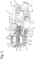
- the driving unit 3 here also comprises a failsafe mechanism 8, of which an auxiliary driving motor 9, worm 10, clutch gear 11 and clutch ring 12 are visible in Figure 1 .
- a failsafe mechanism 8 In case of a calamity, for example a fire in the motor compartment, or a sudden power failure, the failsafe mechanism 8 is activated, and the failsafe mechanism 8 will adjust the output shaft 6 to a predefined position, for example to an open position of the air inlet.
- FIG. 2 shows an exploded perspective view of the adjustment device 1.
- the driving unit 3 is shown in exploded condition.
- the first part 3a is around the input axis A and the second part 3b is around the output axis B.
- the first part 3a comprises a main driving motor 13 provided with a worm wheel 14.
- the components of the first part 3a of the driving unit 3 center around this rod-shaped element 15.
- the worm wheel 14 can cooperate with an input shaft element 16.
- the input shaft element 16 comprises a worm gear 16a, which can cooperate with worm 14, and comprises a sun gear 16b which forms an input of a planetary gear system 17.
- the planetary gear system 17 comprises, in addition to the sun gear 16b, three planet gears 18, a planet carrier 19 and a ring gear 20.
- the ring gear 20 is provided with an internal toothing 21 which is configured to cooperate with the planet gears 18.
- the ring gear 20 is provided with an external toothing 22 which is configured to cooperate with a coupling gear 26 which is situated around axis B and is positioned rotatably and centered around the output shaft element 6.
- the planet gears 18 are positioned on a planet carrier 19, consisting of a carrying part 19a and a gear part 19b. Gear part 19b cooperates with the output gear 23.
- the second part 3b of the driving unit 3 comprises, in addition to the output gear 23, a coupling gear 26 which is rotatably positioned around the output gear 23.
- the coupling gear 26 is preferably rotatably positioned relative to the output gear 23.
- tension spring 27 is connectible on one side, by end 27a, to the coupling gear 26, and connectible on the other side, by end 27b, to the fixed world, in this case the housing 2 of the adjustment device 1.
- the failsafe mechanism 8 in this exemplary embodiment further comprises a small biasing spring 25 for biasing the clutch gear 11 to a release position.
- the driving unit 3 is shown in a rear view, where the main driving motor 13 is visible.
- the working of the driving unit 3 is as follows.
- the main driving motor 13 drives, via the worm 14 and the worm gear 16a, the sun gear 16b.
- the ring gear 20 of the planetary gear system 17, in normal operating condition, is blocked for rotation by means of the clutch ring 12. Because the ring gear 20 engages by the outer toothing 22 into coupling gear 26, in this way the coupling gear 26 is likewise blocked for rotation and, via the clutch ring 12, nonrotatably connected with the fixed world, namely, the housing 2 of the adjustment device 1.
- the planet carrier 19 is the output of the planetary gear system 17. As is known for a planetary gear system, a rotation of the sun gear 16b sets the planet gears 18 in motion and also the planet carrier 19, as output of the planetary gear system 17. The planet carrier 19 in engagement is coupled with the output gear 23 of the second part 3b of the driving unit 3, and thus sets the output gear 23 in motion to adjust the air inlet.
- a first end 27a of the tension spring 27 engages behind a lip 30 of the coupling gear 26. In this way, the tension spring 27 is connected with the coupling gear 26.
- the biasing spring 25 can be omitted; in that case, the adjustment device 1 is provided with a park mechanism 28, as shown in Figure 4 .
- the park mechanism 28 comprises capacitors 29 as energy storage elements. This makes it possible, as when parking the vehicle whereby the electrical current supply to the adjustment device is cut off, that not the failsafe mechanism is activated, but the park mechanism 28 is activated. Because of the absence of the biasing spring 25, there is no bias of the clutch gear 11 to the release position. The auxiliary driving motor 9 will therefore adjust the clutch gear 11 to a blocking position and keep it there during the normal operating condition.
- the park mechanism 28 provides that the failsafe mechanism does not discharge and the driving unit remains unchanged, so that the shutoff elements remain in the position they were in prior to parking.
- the park mechanism 28 may be configured to remember the position of the shutoff elements prior to parking and to adjust the shutoff elements during parking to the open or closed position by the discharge of electrical energy from the capacitors 29 via the auxiliary driving motor 9 and the clutch gear 11 and after parking to readjust them to the prior position.
- the park mechanism 28 may be provided with a control unit for remembering the prior position and/or controlling the auxiliary driving motor 9.
- a vehicle control unit Prior to parking, usually, a vehicle control unit first receives a park signal which indicates that the vehicle is being parked. In the absence of such a park signal, upon cut-off of, for example, the current supply, this will be detected as a calamity and the failsafe mechanism will come into operation. In the case of a failsafe condition, the park mechanism can, by discharge of the energy from the energy storage element 29 to the failsafe mechanism 8, activate the failsafe mechanism.
- connecting element 31 which is accessible through the entry opening 4 of the housing 2.
- the connecting element 31 is configured to receive a corresponding connecting element, for example of an onboard system.
- the connecting elements are preferably implemented as known connecting elements for vehicle systems.
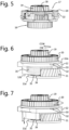
- Figure 5 shows the planetary gear system 17 in detail. including the input shaft element 16, a combined worm gear 16a and sun gear 16b, the planet gears 18 and the planet carrier 19.
- the ring gear 20 Arranged over the planet carrier 19 is the ring gear 20, provided with an inner toothing 21 which engages the planet gears 18 and an outer toothing 22 which engages in the coupling gear 26.
- the ring gear 20 is provided with ring gear cams 32 which cooperate with recesses 33 in an upper side 12a of the clutch ring 12.
- the clutch ring 12 itself is provided at an underside 12b with clutch ring cams 34 which fit into recesses 35 of the clutch gear 11.
- the biasing spring 25 (not shown in Figure 6 , but shown in Figure 2 ) the clutch gear 11 is biased clockwise CW, as seen in the view of Figure 6 .
- the angular displacement of the clutch gear 11 is relatively limited, approximately between 10 and 20 degrees, preferably approximately 15 degrees.
- the clutch ring cams 34 are then on an upper side 11a of the clutch gear 11, so that the clutch gear 11 can rotatably move under the clutch ring 12.
- the main driving motor 13 can drive the driving unit 3 without hindrance from the failsafe mechanism 8.
- the failsafe mechanism 8 When there is a calamity, the failsafe mechanism 8 is activated. The current supply then drops out, and the main driving motor 13 and the auxiliary driving motor 9 have no current anymore. The auxiliary driving motor 9 then stops pulling the clutch gear 11 towards itself, and the clutch gear 11, under the influence of the biasing spring 25, moves clockwise CW through the relatively small angular displacement of approximately between 10 and 20 degrees, preferably approximately 15 degrees, to an unblocking position, as shown in Figure 10b and Figure 8 , in which the ring gear 20 is unblocked in that the clutch ring 12 is connected with the clutch gear 11, and the ring gear 20 is rotatable relative to the clutch ring 12.
- the worm 10 can move along with the clutch gear 11.
- the clutch ring cams 33 can fall into the recesses 34 in the upper side 11a of the clutch gear 11.
- the clutch ring 12 at that moment is then fixedly connected with the clutch gear 11 and thereby moves downwards, in direction D, as can be seen in Figure 7 .
- the ring gear cams 32 are released from the recesses 33 in which they were confined. In this way, the ring gear 20 is released from the rotation lock, and the ring gear 20 can rotate, as shown in Figure 8 .
- the ring gear 20 engages by way of the external toothing 22 into the coupling gear 26.
- This coupling gear 26 is connected with the tension spring 27.
- the coupling gear 26 can rotate under the influence of the tension spring 27, and the coupling with the fixed world, i.e., the housing 2, is undone.
- the ring gear 20 will then move along, as shown in Figure 9 .
- the coupling gear 26 and the ring gear 20 are now disengaged from the connection with the fixed world, namely the housing 2 via the clutch ring 12, and are now freely rotatable.
- the sun gear 16 of the planetary gear system 17 does not rotate, since the main driving motor 13 is provided with a self-braking drive, the inner toothing 21 of the ring gear 20 will drive the planets 18 and thereby also the planet carrier 19, a characteristic property of a planetary gear system, which will be clear to those skilled in the art. This has as a consequence that also the output gear 23 rotates and sets the output shaft element 6 in motion to adjust the air inlet to the predefined position.
- the biasing spring 25 is lacking.
- the auxiliary driving motor 9 holds the clutch gear 11 pulled towards itself, counterclockwise CCW, in a same blocking position as shown in Figure 10a .
- the auxiliary driving motor 9 does not need to be under electrical energization permanently, since there is no biasing spring 25 now whose biasing tension needs to be overcome continuously.
- the auxiliary driving motor 9 also has no current anymore.
- the capacitors 29 can discharge and carry current to the auxiliary driving motor 9, with which the auxiliary driving motor 9 can push the clutch gear 11 clockwise CW until the clutch ring cams 34 fall into the recesses 35 on the upper side 11a of the clutch gear, and the clutch gear 11 is in the unblocking position.
- the operation of the failsafe mechanism 8 is as described above, and the position as shown in Figure 10b can be achieved.
- the driving unit 3 When the driving unit 3 is provided with the park mechanism 28, then, upon the parking of the car, and hence upon the controlled shutting off of the current supply, no change in the driving unit 3 will come about, because the biasing spring 25 is lacking. Only in the case of a calamity, upon an unforeseen or an uncontrolled shutoff of the current supply, will the failsafe mechanism 8 come into operation.
- the driving unit 3 In the case of parking, the driving unit 3, in particular a control unit of the driving unit 3, receives a 'park' signal from the onboard system prior to the controlled shutoff of the current supply. Thereupon the control unit can block the discharge of the capacitors. In the absence of this parking signal and upon drop-out of the current supply, it may be said that a calamity is in evidence, and the failsafe mechanism 8 will come into operation by the discharge of the capacitors 29.
- the current of the capacitors 29 may also be used, prior to startup of the engine of the motor vehicle, to check whether electricity cables and/or data cables and/or other cables are still intact, that is, whether current and/or data can still pass through them.
- (stone) martens are quite common; they can gnaw through cables and/or lines while the vehicle is parked.
- the control unit of the driving unit 3 can, for instance, maintain the parking condition, or alternatively choose to put the failsafe mechanism into operation after all.
- the failsafe mechanism 8 can be reset when there is current supply again.
- the main driving motor 13 drives the planetary gear system 17, and the planet carrier 19 adjusts the output shaft element 6 to a predefined position, usually a first position of the air influencing element.
- the air influencing element for example the strips of the air inlet or the air dam or the wing
- the planet carrier 19 will also be unable to rotate any further and will block.
- the ring gear 20 Via the planets 18, the ring gear 20 will then be driven until the tension spring 27 is fully tensioned and the driving unit 3 blocks.
- the current supply remains in operation, but due to the blocked driving unit 3 the main driving motor 13 will also block, which leads to an increased current, the so-called stalling current.
- This stalling current is detected and thereupon the auxiliary driving motor 9 is provided with current.
- the auxiliary driving motor 9 can thereupon rotate the clutch gear 11 and the clutch ring 12 to the blocking position, against the bias of the biasing spring 25, or not so, depending on the embodiment.
- the driving unit 3 may be provided with a control unit.
- This control unit may be situated in the housing of the adjustment device 1, for example on a printed circuit board 36 as shown in Figure 4 .
- the control unit may also be outside the housing.
- the control unit may be configured to receive signals from the onboard system, but may also be configured, in addition, to feed signals back to the onboard system, for example about the operating condition of the driving unit.
- FIGS 11a and 11b show an alternative embodiment of the failsafe mechanism 8.
- the failsafe mechanism 8 is implemented with a cam gear 37 instead of the clutch ring 12 and the clutch gear 11 of the preceding embodiment.
- the cam gear 37 on one side cooperates with the ring gear 20 and on the other cooperates with the worm 10 of the auxiliary driving motor 9.
- the cam gear 37 analogously to the clutch ring 11, is provided with a toothing 38.
- the cam gear 37 is provided with a recess 39 into which fits a cam 40 of the ring gear 20.
- the cam gear 37 is rotatably attached to the fixed world, i.e., the housing 2, around a rotation axis C.
- no park mechanism is provided.
- This means that the auxiliary driving motor 9 is continuously in driving condition and pulls the cam gear 37 towards itself.
- there is no need for a small biasing spring because the ring gear 20 with the coupling gear 26 are biased by the tension spring 27.
- the cam 40 and the recess 39 are so configured that the cam gear 37 is not self-blocking relative to the ring gear 20.
- a spring - not shown - the ring gear 20 is biased for a clockwise rotation, so that the cam 40 is pushed against a surface 39a of the recess, under the influence of the spring action.
- the cam gear 37 thus retains the cam 40 of the ring gear 20 in the blocking position, and the auxiliary driving motor 9 pulls the cam gear 37 towards itself constantly, against the force of the spring action, of, for example, a tension spring 27.
- the spring action for biasing the ring gear 20 is implemented as in the implementation of Figures 1 to 10 , utilizing a coupling gear 26 and a tension spring 27. Other variants are obviously also possible.
- a reaction force F of the cam 40 on the cam gear 37, resulting from the spring action, is not self-blocking because the surface 39a of the recess 39 against which the cam 40 abuts includes an angle alpha with respect to a line of action W through the rotation axis C.
- the angle alpha is preferably ⁇ 90 degrees.
- This line of action W is parallel to the reaction force F, but, because of the geometry of the cam 40 and the surface 39a, does not coincide with it.
- the reaction force F exerts a moment around the rotation axis C, thus seeking to 'push away' the cam gear 37 counterclockwise CCW.
- the current supply drops out and hence also the drive by the auxiliary driving motor 9, and the moment exerted by the reaction force F provides that the cam gear 37 is 'pushed away' around rotation axis C and the blocking of the ring gear 20 is undone.
- the ring gear 20 can now, under the influence of the spring action of, for example, the tension spring 27, rotate freely, because of the non-self-braking drive of the auxiliary driving motor 9.
- the sun gear 16 of the planetary gear system 17, by contrast, is blocked by the self-braking drive 14 of the main driving motor 13, so that the planet carrier 19 can rotate. Because of the planet carrier 19 being coupled with the output gear 23, the output shaft element 6 and thus the air influencing element can be adjusted to the predefined position.
- This embodiment is more compact than the embodiment shown in Figures 1 to 10 .
- the failsafe spring 25, the clutch ring 12 and the clutch gear 11 have been omitted here.
- Figures 12a and 12b show a variant on the embodiment of Figures 11a to 11b , in which a park mechanism is provided.
- the park mechanism 28, while not shown, may, similarly to the embodiment of Figures 3, 4 or Figures 10a , 10b , comprise capacitors 29.
- the ring gear 20, under the influence of spring action, for example of a tension spring 27, is biased for a clockwise CW rotation.
- the auxiliary driving motor 9 brings the cam gear 27 to the blocking position, so that the cam 40 can be retained in the recess 39. Due to the configuration of the cam 40 and corresponding recess 39, the cam 40 remains in the recess 39 despite the spring action on the ring gear 20. Because of this, the auxiliary driving motor 9 does not need to energize the cam gear 37 constantly.
- the failsafe mechanism 8 here likewise comprises a cam gear 37 which is provided with a recess 39 that cooperates with a cam 40 of the ring gear 20.
- the surface 39a here includes an angle alpha that is greater than or equal to 90 degrees with the line of action W.
- the cam 40 is shaped correspondingly to the surface 39a. Because of the friction of the cam 40 with the surface 39a and because of the geometry of the surface 39a, the reaction force F now exerts a self-blocking effect. As a result, the cam gear 37, under the influence of the spring action of the ring gear 20, remains coupled with the cam 40 by the force F.
- the auxiliary driving motor 9 hence does not have to drive the cam gear 37 continuously.
- the capacitors 29 of the park mechanism 28 will discharge, and drive the auxiliary driving motor 9 to pull the cam gear 37 away from the cam 40, so that the cam 40 comes clear of the recess 39.
- the cam gear 37 is uncoupled from the ring gear 20 and the ring gear 20 can rotate under the influence of the spring action, so that the output shaft element 6 can be adjusted.
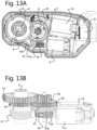
- the failsafe mechanism 8 comprises a wrap spring 41 and an auxiliary driving motor 9, shown in Figures 13a, 13b .
- An optional biasing spring 25, a clutch gear 11, 37 or clutch ring 12 has been omitted here.
- the wrap spring 41 is connected on one side with the worm 10 of the auxiliary driving motor 9, and on the other side with the fixed world, i.e., the housing 2.
- the wrap spring 41 is situated around the ring gear 20 to block the ring gear 20 in a blocking position.
- the working of a wrap spring is well known and is based on a normal force exerted between the spring and the corresponding part, here a collar of the ring gear 20.
- the wrap spring 41 when the current supply is interrupted, the auxiliary driving motor 9 has no current anymore, and the wrap spring 41, because of the non-self-braking drive of the auxiliary driving motor 9, can relax. As a result of the wrap spring 41 relaxing, the ring gear 20 is uncoupled from the wrap spring 41, and the ring gear 20 can rotate freely.
- an additional biasing spring may be provided in order to bring the worm 10 with wrap spring 41 to the biased position in case of a calamity.
- the coupling gear 26 and thus the output gear 23 can adjust to the predefined position.
- the wrap spring 41 once brought in the tensioned position, can remain in the tensioned position and be pulled out of the tensioned position by the auxiliary driving motor 9 in case of a calamity.
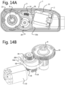
- Figures 14a, 14b , 14c , 15a, 15b show embodiments of an adjustment device 1 without failsafe mechanism, but provided with a ring gear 20.
- a break element 50 the ring gear 20 is breakably connected with the fixed world, i.e., the housing 2.
- the driving unit 3 comprises components the same as or similar to the driving unit 3 of the foregoing embodiments.
- the driving unit 3 comprises a driving motor 13, usually an electric motor, which, via a worm 14, drives an input shaft element 16.
- the planet gears 18, which are supported on the carrying part 19a of the planet carrier 19, are set in motion.
- the ring gear 20 which is provided with an inner toothing is breakably connected, via the break element 50, with the fixed world and in normal operating condition is fixed.
- the gear part 19b of the carrier 19 is coupled with the output gear 23 to set the output shaft element 6 in motion to thus adjust an element to be adjusted, such as a valve or a strip or an air dam or a wing.
- a first part 3a of the driving unit 3 is centered around the first axis A
- a second part 3b of the driving unit 3 is centered around the second axis B, which is parallel to the first axis A.
- the ring gear 20 comes clear of the fixed world and can rotate, as a result of which the element to be adjusted, due to the self-braking drive of the main driving motor 13, can adjust. This obviates or reduces damage to the element to be adjusted caused by external impact. This is relevant in particular for so-called air dams or spoilers. Such air dams or spoilers can be present at different points on a motor vehicle, especially under the vehicle, where they are especially susceptible to external impact.
- the ring gear 20 with the break element 50 damage resulting from external impact can be reduced or obviated and the valve can, as a result of such external impact, be adjusted to a predefined position, usually the closed position.
- the break element 50 is implemented as a U-shaped spring which is retained by its ends 51a, 51b in the housing 2 and which is provided with small kinks 52 by which the break element, such as a spring 50, can be received in recesses 201 of the ring gear 20. Due to the spring action of the U-shaped break element 50, here the U-shaped spring 50, the U-shaped spring clenches the ring gear 20, as it were, and thus the spring 50 locks the ring gear 20. Upon too great an external impact, greater than the biasing force of the spring, the lock between the kinks 52 and the recesses 201 can be broken and the ring gear 20 can rotate freely.
- the break element 50 is implemented as a wrap spring, which, in tensioned position, strangles the ring gear 20, so to speak, and thus retains it.
- Ends 51a, 51b of the wrap spring 50 are situated around a projection 2' of the housing and in this way can push off from the fixed world, namely the projection 2'.
- the wrap spring 50 can thus expand in diameter and in this way uncouple the ring gear 20, so that the ring gear 20 can rotate freely and can adjust the output shaft 6 in a similar manner to that in the foregoing embodiment described.
- the invention has been elucidated hereinabove for air influencing elements for a motor vehicle.
- the adjustment device may be implemented and applied in the same manner for an adjustment device for adjusting fluid influencing elements, such as a liquid valve which may for instance be placed in a pipe.
- the adjustment device can have many uses, in particular for adjustment of valves, such as liquid valves.
- An aspect of the invention therefore also concerns an adjustment device for adjusting a fluid influencing element, such as a valve, between at least a first position and a second position, comprising a driving unit for adjusting the fluid influencing element between at least the first position and the second position provided with an input shaft and an output shaft which is at a distance from the axis of the input shaft, wherein the driving unit has a first part which is provided around the input shaft of the driving unit, and a second part which is provided around the output shaft of the driving unit, wherein the adjustment device is furthermore provided with a failsafe mechanism, wherein the failsafe mechanism engages the first part of the driving unit, wherein the failsafe mechanism comprises an auxiliary driving motor, separately from a main driving motor of the driving unit.
- Adjustment device 1 Housing 2 First housing part 2a Second housing part 2b Driving unit 3 Entry opening housing 4 Exit opening housing 5 Output shaft element 6 Gear coupling 7 Failsafe mechanism 8 Auxiliary driving motor 9 Worm (auxiliary driving motor) 10 Clutch gear 11 Upper side clutch gear 11a Clutch ring 12 Upper side clutch ring 12a Underside clutch ring 12b Main driving motor 13 Worm (main driving motor) 14 Rod-shaped element 15 Input shaft element 16 Worm gear 16a Sun gear 16b Planetary gear system 17 Planet gears 18 Planet carrier 19 Carrying part 19a Gear part 19b Ring gear 20 Internal toothing ring gear 21 External toothing ring gear 22 Output gear 23 VOID 24 Biasing spring 25 Coupling gear 26 Tension spring 27 First end tension spring 27a Second end tension spring 27b Park mechanism 28 Capacitor 29 Lip 30 Connecting element 31 Ring gear cams 32 Recess 33 Clutch ring cams 34 Recess clutch gear 35 Printed circuit board 36 Cam gear 37 Cam gear toothing 38 Recess cam gear 39 Surface of rece
Landscapes
- Engineering & Computer Science (AREA)
- General Engineering & Computer Science (AREA)
- Mechanical Engineering (AREA)
- Chemical & Material Sciences (AREA)
- Combustion & Propulsion (AREA)
- Transportation (AREA)
- Connection Of Motors, Electrical Generators, Mechanical Devices, And The Like (AREA)
- Retarders (AREA)
- One-Way And Automatic Clutches, And Combinations Of Different Clutches (AREA)
- Cooling, Air Intake And Gas Exhaust, And Fuel Tank Arrangements In Propulsion Units (AREA)
- Gear-Shifting Mechanisms (AREA)
Description
- The invention relates to an adjustment device for adjusting an air influencing element of a motor vehicle.
- An air influencing element can be, for example, an air inlet of a motor vehicle, in particular adjustable strips or flaps of the air inlet. An air influencing element can be, for example, a wing which is situated at an outer side of a motor vehicle, or an air dam or spoiler which is situated at an underside of a motor vehicle. The air influencing elements, also called air guiding elements, guide or manipulate an air stream in and/or around a vehicle.
- It is known to make an air influencing element, such as an air inlet of a motor compartment, adjustable, whereby the air inlet can be adjusted between an open position and a closed position. To this end, the air inlet may be provided with elements to be adjusted, for example strips or flaps, which can be adjusted, for example pivoted about an upright or lying axis.
- In the closed position of the air inlet the air resistance of the vehicle is lowered, which is beneficial to the fuel consumption of the motor. Further, where the efficiency of the motor, fuel consumption and CO2 emission are concerned, a motor of a motor vehicle has an optimum operating temperature, which is typically higher than the ambient temperature. A closed air inlet when the motor is cold is then once again beneficial to fuel consumption. Also, during driving with an open air inlet, the temperature of the motor can fall below the optimum operating temperature, so that fuel consumption may increase. Fuel consumption of the motor may also increase at an operating temperature above the optimum operating temperature.
- A motor vehicle may be provided with one or more wings as air influencing elements. A wing may be situated, for example, at the back of the vehicle, or at a side or at a front. Particularly at high speeds of the vehicle, a wing can provide for downward force to keep the vehicle stably on the ground. At low speeds, by contrast, a wing generates mainly resistance, which leads to more fuel consumption. It is hence advantageous to make a spoiler adjustable.
- A motor vehicle may be provided with one or more spoilers as air influencing elements. A spoiler is intended for disturbing unwanted air streams around the vehicle, so that resistance can diminish. A spoiler may be situated at a back, a side, a front or also a bottom of the vehicle. When a spoiler is situated at a front or a bottom, it is also called air dam. In particular when a spoiler, or air dam, is situated at a bottom of the vehicle, and there, by influencing air streams, can thus reduce the development of whirls between the underside of the vehicle and the road, the resistance of the vehicle during driving can diminish, which can lead to less fuel consumption. However, when an air dam extends at the underside of the vehicle, it is exposed to obstacles that are on the road, such as a speed bump, or loose chippings or grit. This can lead to damage of the air dam. It may hence be advantageous to make an air dam, in particular an air dam at an underside of the vehicle, adjustable.
- It may be advantageous, then, to make an air influencing element of a motor vehicle adjustable. To this end, the air influencing element is usually coupled to an adjustment device which comprises a driving unit. With the aid of the driving unit, the air influencing element can be adjusted between a first position and a second position. When in the case of a closed air inlet the operating temperature of the motor runs up too high, the air inlet can be opened again to provide for sufficient cooling. A wing or an air dam may be adjusted, for example, between a first position in which they extend substantially along the vehicle and a second position in which they extend from the vehicle at an angle.
- For an air inlet, solutions are known to allow the air inlet, in case of a failure in the adjustment device, still to be opened when closed. Such a failsafe provision in an adjustment device is used in order to adjust, in case of a calamity, the shutoff elements of the air inlet to a predefined position, usually the open position of the shutoff elements.
- Publication
WO 2013/012337 , for example, describes an adjustment device with a failsafe provision which comprises a spring which is connected to the output shaft of the adjustment device. The spring is retained, against the spring tension, by an arm which is retained under the influence of magnetic force. In case of a calamity, such as power failure, the magnetic force drops out and the arm moves to release the spring. Under the influence of the spring force, the output shaft of the adjustment device is thus adjusted to the open position. -
Publication DE 39 05 717 describes an adjustment device having a first driving motor and a second driving motor both driving motors coupled to the output shaft. In case of failure of one of the driving motors, the other one can take over the functionality of the failed driving motor.
A disadvantage of the known adjustment device is that it may be relatively voluminous, and does not always fit within the space available in the vehicle. Also, by the use of tolerance-sensitive parts, the reliability of the adjustment device may sometimes leave to be desired. Also, it has appeared that the adjustment device is relatively expensive. - An object of the invention is to provide an adjustment device that counteracts at least one of the above-mentioned disadvantages. In particular, it is desired to provide an adjustment device that can be relatively compact and/or inexpensive and/or reliable.
- To this end, the invention provides an adjustment device for adjusting an air influencing element of a motor vehicle according to
claim 1. - Advantageously, the second part of the driving unit may be situated around the axis of the output shaft, while, preferably, the output shaft is at a distance from the input shaft, so that the driving unit can be made of relatively compact design. More preferably, the output shaft is approximately parallel to the input shaft, in this way the driving unit can be made of relatively flat design.
- The adjustment device is provided with a failsafe mechanism. The failsafe mechanism is activated in the event of a calamity, for example in case of power failure or in case of fire in the motor compartment for an air inlet, or when an air dam or a spoiler contacts an obstacle. The failsafe mechanism is configured, in the event of a calamity, to adjust the air influencing element to a predefined position, for example the first position, or the second position. The failsafe mechanism is configured to engage the first part of the driving unit. In contrast to known failsafe mechanisms, which engage the output shaft directly, the failsafe mechanism in accordance with the invention engages the first part of the driving unit which is positioned around the input shaft. Thus, the failsafe mechanism can be made of lighter design, since it is not directly subject to the forces acting on the output shaft of the driving unit. This is because, preferably, the second part is coupled to the first part with a transmission ratio, the transmission ratio being chosen such that the forces on the first part of the driving unit are smaller than on the second part, with the output shaft. Due to the failsafe mechanism engaging the first part, the forces that the failsafe mechanism experiences are also smaller, so that the failsafe mechanism can be made of lighter and more compact design.
- The failsafe mechanism can comprise different parts, but engages, in accordance with the invention, the first part of the driving unit. Parts or components of the failsafe mechanism may be situated in the first part of the driving unit, around the input shaft, and/or parts or components of the failsafe mechanism may be situated in the second part of the driving unit, around the output shaft, and/or parts or components of the failsafe mechanism may be situated next to the first part and/or the second part of the driving unit. Many variants and positions of the failsafe mechanism and/or components of the failsafe mechanism are thus possible, with the failsafe mechanism in each case engaging the first part of the driving unit.
- Thus, for example, there may be provided an energy element, such as a tension spring, which is pretensioned (biased) to the predefined position of the air influencing elements in the case where the failsafe mechanism comes into operation. Such a tension spring, or other elastic element, can provide the energy that is needed to adjust the air influencing elements in the event of a calamity to the predefined position, via the driving unit. For example, the tension spring may by one end be connectible, detachably or undetachably, with the first part of the driving unit, or with the second part of the driving unit, and by another end be connected with the fixed world. The tension spring may be situated in the second part of the driving unit, or in the first part of the driving unit, or may be placed in the driving unit separately from the first part and from the second part. The failsafe mechanism itself engages the first part of the driving unit, for example by retaining or blocking an element or component of the first part and releasing this component in case of a calamity. Whereupon, for example, the energy can be released from the tension spring to adjust the output shaft, whether or not via the first part of the driving unit, to the predefined position of the air influencing elements.
- By coupling the second part of the driving unit to the first part of the driving unit with a transmission ratio, the first part of the driving unit, as well as the failsafe mechanism, can be made of lighter design. After all, not the full forces on the output shaft then act on the first part and/or the failsafe mechanism, but only a part of those forces in accordance with the transmission ratio. For example, if the transmission ratio of the coupling between the first part and the second part is one to three, then the first part of the driving unit and/or the failsafe mechanism only experience one-third of the forces on the output shaft. This way, the first part and/or the failsafe mechanism can hence be lighter and cheaper in design. Obviously, other transmission ratios can also be possible.
- Advantageously, the input shaft is connected with a main driving motor and the output shaft is configured to be connectible with the air influencing element. This way, the adjustment device can be coupled with the air influencing element in a compact manner. For example, the adjustment device may be provided with a housing. The main driving motor may be situated in the housing, while the output shaft of the driving unit can extend through the housing, thus being simply couplable with the air influencing element, for example with shutoff elements of the air inlet, with the spoiler or with the air dam.
- Advantageously, the first part of the driving unit comprises a planetary gear system, comprising a sun gear, at least one planet gear, a planet carrier and a ring gear, while the sun gear is connected with the input shaft. The second part of the driving unit comprises an output gear which forms the output shaft of the driving unit.
- The output gear of the second part of the driving unit is coupled with a transmission ratio to an output of the planetary gear system, for example the planet carrier. Thus, the transmission ratio between the first part and the second part can be realized in a simple manner.
- The ring gear of the planetary gear system is preferably detachably connected with the fixed world, for example a housing of the adjustment device. By providing the ring gear as being detachably connectible with the fixed world, the failsafe mechanism, when activated, can drive the ring gear as a second input of the planetary gear system. Advantageously, the failsafe mechanism is configured to uncouple the ring gear of the planetary gear system from the fixed world, in a failsafe condition, to adjust the output of the second part of the driving unit. In this way, then, via the ring gear, the second part of the driving unit can be driven in a failsafe condition, for example via a coupling gear. The coupling gear is preferably positioned rotatably centered around the output gear of the second part of the driving unit and is rotatably coupled with the ring gear of the planetary gear system of the first part of the driving unit, preferably rotatably coupled with an external toothing on the ring gear of the planetary gear system of the first part of the driving unit. The coupling gear is advantageously pretensioned (biased) to a predefined position, for example under the influence of an elastic element such as a spring element. By biasing the coupling gear to the predefined position, in the event of a failsafe condition, the output shaft can be adjusted to the predefined position under the influence of the bias. The coupling gear is, via the ring gear, detachably connected with the fixed world, for example the housing. In the event of a calamity, the failsafe mechanism will break the coupling of the coupling gear with the fixed world, and, via the ring gear and the planetary gear system, the output gear can still be adjusted for adjustment of the air inlet to the predefined position.
- The failsafe mechanism is usually provided with an energy storage element and/or an activation element. The activation element can undo the ring gear's rotation-lock with the fixed world. Advantageously, the activation element is here implemented as an auxiliary driving motor. By providing an auxiliary driving motor, the relatively expensive and error-sensitive magnetic coupling element of known failsafe mechanisms can be replaced with a cheaper and more reliable auxiliary driving motor. Also, the provision of an auxiliary driving motor allows the driving unit to be made of a more compact design, since the auxiliary driving motor can take up less space than the known magnetic coupling element. The auxiliary driving motor is separate from the main driving motor, so that upon activation of the failsafe mechanism the drive of the air inlet does not proceed via the main driving motor. Also, the auxiliary driving motor drives merely the failsafe mechanism and not the output shaft. This in contrast to the main driving motor, which, via the first part and the second part of the driving unit, drives the output shaft and thereby adjusts the air influencing elements. The auxiliary driving motor, by contrast, adjusts merely the failsafe mechanism, whereby, through adjustment of the failsafe mechanism, an energy element, such as for example a tension spring, releases energy to adjust the output shaft. The auxiliary driving motor is configured for merely driving the failsafe mechanism, and is not configured for driving the output shaft. Because of this, the auxiliary driving motor can be relatively light in design.
- The first part of the driving unit can comprise a clutch ring which is axially movable in a direction of the input shaft of the first part of the driving unit and is nonrotatably connected with the fixed world, for example a housing of the adjustment device, and/or the ring gear is detachably coupled with the clutch ring. By providing a clutch ring, the ring gear can be detachably couplable with the fixed world in a simple manner. The clutch ring may be axially movable and thus retain or release the ring gear under the influence of the failsafe mechanism, for example under the influence of the adjustment of a clutch gear. The clutch gear is couplable with the clutch ring, while the clutch ring is configured to be pretensioned to a release position, in the event of a failsafe condition, under the influence of an elastic element, and is configured to be held by the auxiliary driving motor, against the force of the pretension (bias), in a blocking position.
- Advantageously, the adjustment device comprises a park mechanism, so that when the vehicle is parked, and hence the electrical current supply to the adjustment device is shut off, not the failsafe mechanism is activated, but the park mechanism is activated. In the adjustment device provided with the park mechanism, the bias of the clutch gear to the release position is lacking. The auxiliary driving motor will hence adjust the clutch gear to a blocking position. In the case of a park condition, the park mechanism can leave the driving unit stationary, i.e. unchanged. In the case of a failsafe condition, the park mechanism can, by discharge of the energy from the energy storage element to the failsafe mechanism, activate the failsafe mechanism. Prior to parking, usually, a vehicle control unit first receives a park signal indicating that the vehicle is being parked. In the absence of such park signal, then, when for example the current supply drops out, this will be detected as a calamity and the failsafe mechanism will come into operation.
- Further advantageous embodiments are represented in the dependent claims.
- The invention also relates to an air inlet provided with such an adjustment device, to a vehicle provided with such an air inlet, and to a method for adjusting an air inlet.
- The invention will be further explained on the basis of an exemplary embodiment which is represented in a drawing. The drawing shows in the figures:
-
Fig. 1 a schematic perspective view of an adjustment device according to the invention; -
Fig. 2 a schematic exploded view of the adjustment device according toFig. 1 ; -
Fig. 3 a schematic rear view of the driving unit ofFig. 1 ; -
Fig. 4 a schematic perspective view of a driving unit of an adjustment device; -
Fig. 5 a detail of the driving unit ofFig. 4 ; -
Fig. 6 the detail ofFig. 5 provided with a clutch ring and a clutch gear; -
Fig. 7 a first part of the driving unit in normal operating condition; -
Fig. 8 the first part of the driving unit when the failsafe mechanism is activated; -
Fig. 9 the first part of the driving unit in failsafe condition; -
Fig. 10a the driving unit with the failsafe mechanism not activated; and -
Fig. 10b the driving unit with the failsafe mechanism activated; -
Fig. 11a a schematic top plan view of an alternative embodiment of the driving unit with failsafe mechanism without park mechanism, where the failsafe mechanism is not activated; -
Fig. 11b a detail ofFig. 11a ; -
Fig. 12a a schematic top plan view of an alternative embodiment of the driving unit with failsafe mechanism in case a park mechanism is provided, where the failsafe mechanism is not activated; -
Fig. 12b a detail of the cam gear ofFig. 12a ; -
Fig. 12c the embodiment ofFig. 12a with activated failsafe mechanism; -
Fig. 13a a schematic top plan view of an alternative embodiment of the driving unit with failsafe mechanism, without park mechanism; -
Fig. 13b a schematic perspective view of the embodiment ofFig. 13a ; -
Fig. 14a a schematic top plan view of an embodiment of the driving unit with breakable ring gear without failsafe mechanism; -
Fig. 14b a schematic perspective view of the embodiment ofFig. 14a ; -
Fig. 14c a schematic perspective exploded view of the embodiment ofFig. 14a and Fig. 14b ; -
Fig. 15a a schematic top plan view of a second embodiment of the driving unit with breakable ring gear without failsafe mechanism; -
Fig. 15b a schematic perspective view of the embodiment ofFig. 15a . - It is noted that the Figures are only schematic representations of exemplary embodiments of the invention. Like parts are designated with like reference numerals.
- In
Figure 1 there is shown anadjustment device 1 for adjusting an air influencing element of a motor vehicle. The air influencing element can be an air inlet of a motor compartment, which is usually provided with shutoff elements, such as strips, which are adjustable between a first position, in which the air inlet is substantially closed, and a second position, in which the air inlet is substantially open. The air inlet is not shown here. An air influencing element can also be a spoiler or air dam which is situated preferably at a front or a bottom of the vehicle. The air dam may be adjustable between a first position, in which it extends substantially along the vehicle and a second position, in which it extends from the vehicle at an angle. An air influencing element can also be a wing, which is usually situated at a back or top of the vehicle. The wing may be adjustable between a first position, in which it extends substantially along the vehicle and a second position, in which it extends from the vehicle at an angle, or is at a distance from the vehicle. Theadjustment device 1 is here provided with ahousing 2 and adriving unit 3 which is included in thehousing 2. Thehousing 2 here comprises two parts, afirst housing part 2a in which thedriving unit 3 is situated, and asecond housing part 2b, which is here implemented as a cover to close off thefirst housing part 2a. - The
housing 2 is provided with an entry opening 4 through which a connecting element can be inserted to be connectible to thedriving unit 3. The connecting element can be, for example, a plug of an onboard system, such as a LIN bus system, or other system. The connecting element preferably comprises at least one electricity connection to provide electricity to the driving unit. Optionally, the connecting element may additionally also have a control connection to bring a control signal to the driving unit and/or to bring a control signal from the driving unit back to the onboard system, for example to a central onboard control unit. - The
housing 2 is further provided with at least oneexit opening 5. Through theoutput opening 5 can extend anoutput shaft element 6 of thedriving unit 3 to allow it to be further coupled with the air influencing element, for example with strips of the air inlet, with the air dam or with the wing. - The driving
unit 3 comprises afirst part 3a provided around an axis of the input shaft, hereinafter also input axis A, and comprises asecond part 3b provided around the axis of the output shaft, hereinafter also output axis B. The input axis A is at a distance from the output axis B. Preferably, the input axis A is approximately parallel to the output axis B. Theoutput shaft element 6 is situated concentrically around the output axis B. Theoutput shaft element 6 can extend from an end 6a to theopposite end 6b. The output shaft ends 6a, 6b are preferably situated on either side of thehousing 2 throughopenings housing parts output shaft element 6 can extend as a hollow shaft element along axis B. - The
first part 3a is coupled to thesecond part 3b by a gear coupling 7. By making the gear of thesecond part 3b greater in diameter than the gear of thefirst part 3a, thesecond part 3b of the driving unit can be coupled to thefirst part 3a of thedriving unit 3 with a transmission ratio. In this way, thefirst part 3a of thedriving unit 3 does not experience the full forces that are on theoutput shaft 6, but only, in accordance with the transmission ratio, a part of those forces. Because of this, thefirst part 3a of the driving unit can be lighter and cheaper in design. - The driving
unit 3 here also comprises afailsafe mechanism 8, of which anauxiliary driving motor 9,worm 10,clutch gear 11 andclutch ring 12 are visible inFigure 1 . In case of a calamity, for example a fire in the motor compartment, or a sudden power failure, thefailsafe mechanism 8 is activated, and thefailsafe mechanism 8 will adjust theoutput shaft 6 to a predefined position, for example to an open position of the air inlet. -
Figure 2 shows an exploded perspective view of theadjustment device 1. The drivingunit 3 is shown in exploded condition. Thefirst part 3a is around the input axis A and thesecond part 3b is around the output axis B. Thefirst part 3a comprises amain driving motor 13 provided with aworm wheel 14. There is a rod-shapedelement 15, a central axis of which coincides with the input axis A. The components of thefirst part 3a of thedriving unit 3 center around this rod-shapedelement 15. Theworm wheel 14 can cooperate with aninput shaft element 16. Theinput shaft element 16 comprises aworm gear 16a, which can cooperate withworm 14, and comprises asun gear 16b which forms an input of aplanetary gear system 17. Theplanetary gear system 17 comprises, in addition to thesun gear 16b, threeplanet gears 18, aplanet carrier 19 and aring gear 20. Thering gear 20 is provided with aninternal toothing 21 which is configured to cooperate with the planet gears 18. In addition, thering gear 20 is provided with anexternal toothing 22 which is configured to cooperate with acoupling gear 26 which is situated around axis B and is positioned rotatably and centered around theoutput shaft element 6. The planet gears 18 are positioned on aplanet carrier 19, consisting of a carryingpart 19a and agear part 19b.Gear part 19b cooperates with theoutput gear 23. - The
second part 3b of thedriving unit 3 comprises, in addition to theoutput gear 23, acoupling gear 26 which is rotatably positioned around theoutput gear 23. Thecoupling gear 26 is preferably rotatably positioned relative to theoutput gear 23. - Also provided is a
tension spring 27. Thetension spring 27 is connectible on one side, byend 27a, to thecoupling gear 26, and connectible on the other side, byend 27b, to the fixed world, in this case thehousing 2 of theadjustment device 1. - The
failsafe mechanism 8 in this exemplary embodiment further comprises a small biasing spring 25 for biasing theclutch gear 11 to a release position. - In
Figure 3 , the drivingunit 3 is shown in a rear view, where themain driving motor 13 is visible. The working of thedriving unit 3 is as follows. Themain driving motor 13 drives, via theworm 14 and theworm gear 16a, thesun gear 16b. Thering gear 20 of theplanetary gear system 17, in normal operating condition, is blocked for rotation by means of theclutch ring 12. Because thering gear 20 engages by theouter toothing 22 intocoupling gear 26, in this way thecoupling gear 26 is likewise blocked for rotation and, via theclutch ring 12, nonrotatably connected with the fixed world, namely, thehousing 2 of theadjustment device 1. - The
planet carrier 19 is the output of theplanetary gear system 17. As is known for a planetary gear system, a rotation of thesun gear 16b sets the planet gears 18 in motion and also theplanet carrier 19, as output of theplanetary gear system 17. Theplanet carrier 19 in engagement is coupled with theoutput gear 23 of thesecond part 3b of thedriving unit 3, and thus sets theoutput gear 23 in motion to adjust the air inlet. - In
Fig. 3 it can further be seen that afirst end 27a of thetension spring 27 engages behind alip 30 of thecoupling gear 26. In this way, thetension spring 27 is connected with thecoupling gear 26. - In an exemplary embodiment, the biasing spring 25 can be omitted; in that case, the
adjustment device 1 is provided with apark mechanism 28, as shown inFigure 4 . Thepark mechanism 28 comprisescapacitors 29 as energy storage elements. This makes it possible, as when parking the vehicle whereby the electrical current supply to the adjustment device is cut off, that not the failsafe mechanism is activated, but thepark mechanism 28 is activated. Because of the absence of the biasing spring 25, there is no bias of theclutch gear 11 to the release position. Theauxiliary driving motor 9 will therefore adjust theclutch gear 11 to a blocking position and keep it there during the normal operating condition. In the case of a park condition, thepark mechanism 28 provides that the failsafe mechanism does not discharge and the driving unit remains unchanged, so that the shutoff elements remain in the position they were in prior to parking. Alternatively and/or additionally, thepark mechanism 28 may be configured to remember the position of the shutoff elements prior to parking and to adjust the shutoff elements during parking to the open or closed position by the discharge of electrical energy from thecapacitors 29 via theauxiliary driving motor 9 and theclutch gear 11 and after parking to readjust them to the prior position. To this end, thepark mechanism 28 may be provided with a control unit for remembering the prior position and/or controlling theauxiliary driving motor 9. - Prior to parking, usually, a vehicle control unit first receives a park signal which indicates that the vehicle is being parked. In the absence of such a park signal, upon cut-off of, for example, the current supply, this will be detected as a calamity and the failsafe mechanism will come into operation. In the case of a failsafe condition, the park mechanism can, by discharge of the energy from the
energy storage element 29 to thefailsafe mechanism 8, activate the failsafe mechanism. - In
Figure 4 , there is also shown a connectingelement 31 which is accessible through the entry opening 4 of thehousing 2. The connectingelement 31 is configured to receive a corresponding connecting element, for example of an onboard system. The connecting elements are preferably implemented as known connecting elements for vehicle systems. - The operation of the
failsafe mechanism 8 will be explained on the basis ofFigures 5 - 10b .Figure 5 shows theplanetary gear system 17 in detail. including theinput shaft element 16, a combinedworm gear 16a andsun gear 16b, the planet gears 18 and theplanet carrier 19. Arranged over theplanet carrier 19 is thering gear 20, provided with aninner toothing 21 which engages the planet gears 18 and anouter toothing 22 which engages in thecoupling gear 26. - In
Figure 6 it is shown, furthermore, that thering gear 20 is provided withring gear cams 32 which cooperate withrecesses 33 in anupper side 12a of theclutch ring 12. Theclutch ring 12 itself is provided at anunderside 12b withclutch ring cams 34 which fit intorecesses 35 of theclutch gear 11. By the biasing spring 25 (not shown inFigure 6 , but shown inFigure 2 ) theclutch gear 11 is biased clockwise CW, as seen in the view ofFigure 6 . In normal operating condition, when thefailsafe mechanism 8 is not activated, theclutch gear 11 is held by theauxiliary driving motor 9 in a counterclockwise CCW direction, against the force of the biasing spring 25, by means of a non-self-braking worm-worm gear drive of theauxiliary driving motor 9, in a blocking position, as shown inFigure 10a andFigure 6 , in which theclutch ring 12 is connected with thering gear 20, and theclutch gear 11 is rotatably movable relative to theclutch ring 12. The drive from themain driving motor 13 via theplanetary gear system 17 to theoutput shaft 6 is therefore independent of thefailsafe mechanism 8 comprising theclutch gear 11 and theauxiliary driving motor 9. - The angular displacement of the
clutch gear 11 is relatively limited, approximately between 10 and 20 degrees, preferably approximately 15 degrees. Theclutch ring cams 34 are then on anupper side 11a of theclutch gear 11, so that theclutch gear 11 can rotatably move under theclutch ring 12. Theauxiliary driving motor 9, in normal operating condition, thus holds theclutch gear 11 pulled towards itself, against the bias of the biasing spring 25. Themain driving motor 13 can drive the drivingunit 3 without hindrance from thefailsafe mechanism 8. - When there is a calamity, the
failsafe mechanism 8 is activated. The current supply then drops out, and themain driving motor 13 and theauxiliary driving motor 9 have no current anymore. Theauxiliary driving motor 9 then stops pulling theclutch gear 11 towards itself, and theclutch gear 11, under the influence of the biasing spring 25, moves clockwise CW through the relatively small angular displacement of approximately between 10 and 20 degrees, preferably approximately 15 degrees, to an unblocking position, as shown inFigure 10b andFigure 8 , in which thering gear 20 is unblocked in that theclutch ring 12 is connected with theclutch gear 11, and thering gear 20 is rotatable relative to theclutch ring 12. Due to theauxiliary driving motor 9 being provided with a non-self-braking drive, theworm 10 can move along with theclutch gear 11. As a result of this angular displacement of theclutch gear 11, theclutch ring cams 33 can fall into therecesses 34 in theupper side 11a of theclutch gear 11. Theclutch ring 12 at that moment is then fixedly connected with theclutch gear 11 and thereby moves downwards, in direction D, as can be seen inFigure 7 . As a result of this downward movement of theclutch ring 12, thering gear cams 32 are released from therecesses 33 in which they were confined. In this way, thering gear 20 is released from the rotation lock, and thering gear 20 can rotate, as shown inFigure 8 . - The
ring gear 20 engages by way of theexternal toothing 22 into thecoupling gear 26. Thiscoupling gear 26 is connected with thetension spring 27. As a result of thering gear 20 now being freely rotatable, thecoupling gear 26 can rotate under the influence of thetension spring 27, and the coupling with the fixed world, i.e., thehousing 2, is undone. Thering gear 20 will then move along, as shown inFigure 9 . Thecoupling gear 26 and thering gear 20 are now disengaged from the connection with the fixed world, namely thehousing 2 via theclutch ring 12, and are now freely rotatable. Because thesun gear 16 of theplanetary gear system 17 does not rotate, since themain driving motor 13 is provided with a self-braking drive, theinner toothing 21 of thering gear 20 will drive theplanets 18 and thereby also theplanet carrier 19, a characteristic property of a planetary gear system, which will be clear to those skilled in the art. This has as a consequence that also theoutput gear 23 rotates and sets theoutput shaft element 6 in motion to adjust the air inlet to the predefined position. - In the case where the driving
unit 3 is provided with apark mechanism 28, as shown inFigure 4 , the biasing spring 25 is lacking. In that case, in normal operating condition, theauxiliary driving motor 9 holds theclutch gear 11 pulled towards itself, counterclockwise CCW, in a same blocking position as shown inFigure 10a . For this, theauxiliary driving motor 9 does not need to be under electrical energization permanently, since there is no biasing spring 25 now whose biasing tension needs to be overcome continuously. In the event of a calamity, when the current supply drops out, theauxiliary driving motor 9 also has no current anymore. Then thecapacitors 29 can discharge and carry current to theauxiliary driving motor 9, with which theauxiliary driving motor 9 can push theclutch gear 11 clockwise CW until theclutch ring cams 34 fall into therecesses 35 on theupper side 11a of the clutch gear, and theclutch gear 11 is in the unblocking position. After that, the operation of thefailsafe mechanism 8 is as described above, and the position as shown inFigure 10b can be achieved. - When the driving
unit 3 is provided with thepark mechanism 28, then, upon the parking of the car, and hence upon the controlled shutting off of the current supply, no change in thedriving unit 3 will come about, because the biasing spring 25 is lacking. Only in the case of a calamity, upon an unforeseen or an uncontrolled shutoff of the current supply, will thefailsafe mechanism 8 come into operation. For, in the case of parking, the drivingunit 3, in particular a control unit of thedriving unit 3, receives a 'park' signal from the onboard system prior to the controlled shutoff of the current supply. Thereupon the control unit can block the discharge of the capacitors. In the absence of this parking signal and upon drop-out of the current supply, it may be said that a calamity is in evidence, and thefailsafe mechanism 8 will come into operation by the discharge of thecapacitors 29. - Optionally, the current of the
capacitors 29 may also be used, prior to startup of the engine of the motor vehicle, to check whether electricity cables and/or data cables and/or other cables are still intact, that is, whether current and/or data can still pass through them. In some areas, (stone) martens are quite common; they can gnaw through cables and/or lines while the vehicle is parked. Prior to starting up the engine, by using a little current from the capacitors to check the intactness of the cables, it can be established whether the cables are still intact. Should any of the cables not be entirely intact anymore, this could hinder the current supply to thedriving unit 3, as a result of which thefailsafe mechanism 8 would come into operation, still, upon startup of the engine. By recognizing this beforehand, the control unit of thedriving unit 3 can, for instance, maintain the parking condition, or alternatively choose to put the failsafe mechanism into operation after all. - After activation of the
failsafe mechanism 8, thefailsafe mechanism 8 can be reset when there is current supply again. Themain driving motor 13 drives theplanetary gear system 17, and theplanet carrier 19 adjusts theoutput shaft element 6 to a predefined position, usually a first position of the air influencing element. When the air influencing element, for example the strips of the air inlet or the air dam or the wing, is in an end position, such as the first position, theplanet carrier 19 will also be unable to rotate any further and will block. Via theplanets 18, thering gear 20 will then be driven until thetension spring 27 is fully tensioned and thedriving unit 3 blocks. The current supply remains in operation, but due to the blocked drivingunit 3 themain driving motor 13 will also block, which leads to an increased current, the so-called stalling current. This stalling current is detected and thereupon theauxiliary driving motor 9 is provided with current. Theauxiliary driving motor 9 can thereupon rotate theclutch gear 11 and theclutch ring 12 to the blocking position, against the bias of the biasing spring 25, or not so, depending on the embodiment. - The driving
unit 3 may be provided with a control unit. This control unit may be situated in the housing of theadjustment device 1, for example on a printedcircuit board 36 as shown inFigure 4 . The control unit may also be outside the housing. The control unit may be configured to receive signals from the onboard system, but may also be configured, in addition, to feed signals back to the onboard system, for example about the operating condition of the driving unit. -
Figures 11a and 11b show an alternative embodiment of thefailsafe mechanism 8. In this exemplary embodiment, thefailsafe mechanism 8 is implemented with acam gear 37 instead of theclutch ring 12 and theclutch gear 11 of the preceding embodiment. Thecam gear 37 on one side cooperates with thering gear 20 and on the other cooperates with theworm 10 of theauxiliary driving motor 9. For cooperation with theworm 10, thecam gear 37, analogously to theclutch ring 11, is provided with atoothing 38. For cooperation with thering gear 20, thecam gear 37 is provided with arecess 39 into which fits acam 40 of thering gear 20. Thecam gear 37 is rotatably attached to the fixed world, i.e., thehousing 2, around a rotation axis C. - In this exemplary embodiment, no park mechanism is provided. This means that the
auxiliary driving motor 9 is continuously in driving condition and pulls thecam gear 37 towards itself. In this way, there is no need for a small biasing spring because thering gear 20 with thecoupling gear 26 are biased by thetension spring 27. Thecam 40 and therecess 39 are so configured that thecam gear 37 is not self-blocking relative to thering gear 20. By means of a spring - not shown - thering gear 20 is biased for a clockwise rotation, so that thecam 40 is pushed against asurface 39a of the recess, under the influence of the spring action. Thecam gear 37 thus retains thecam 40 of thering gear 20 in the blocking position, and theauxiliary driving motor 9 pulls thecam gear 37 towards itself constantly, against the force of the spring action, of, for example, atension spring 27. For example, the spring action for biasing thering gear 20 is implemented as in the implementation ofFigures 1 to 10 , utilizing acoupling gear 26 and atension spring 27. Other variants are obviously also possible. - A reaction force F of the
cam 40 on thecam gear 37, resulting from the spring action, is not self-blocking because thesurface 39a of therecess 39 against which thecam 40 abuts includes an angle alpha with respect to a line of action W through the rotation axis C. The angle alpha is preferably <90 degrees. This line of action W is parallel to the reaction force F, but, because of the geometry of thecam 40 and thesurface 39a, does not coincide with it. As a result, the reaction force F exerts a moment around the rotation axis C, thus seeking to 'push away' thecam gear 37 counterclockwise CCW. Hence, an energization from theauxiliary driving motor 9 is constantly necessary to undo this moment and hold thecam 40 blocked in thecam gear 37, as a result of which thering gear 20 is also connected with the fixed world, i.e., thehousing 2, via thecam gear 37. - In the case of a calamity, the current supply drops out and hence also the drive by the
auxiliary driving motor 9, and the moment exerted by the reaction force F provides that thecam gear 37 is 'pushed away' around rotation axis C and the blocking of thering gear 20 is undone. Thering gear 20 can now, under the influence of the spring action of, for example, thetension spring 27, rotate freely, because of the non-self-braking drive of theauxiliary driving motor 9. Thesun gear 16 of theplanetary gear system 17, by contrast, is blocked by the self-brakingdrive 14 of themain driving motor 13, so that theplanet carrier 19 can rotate. Because of theplanet carrier 19 being coupled with theoutput gear 23, theoutput shaft element 6 and thus the air influencing element can be adjusted to the predefined position. - This embodiment is more compact than the embodiment shown in
Figures 1 to 10 . The failsafe spring 25, theclutch ring 12 and theclutch gear 11 have been omitted here. -
Figures 12a and 12b show a variant on the embodiment ofFigures 11a to 11b , in which a park mechanism is provided. Thepark mechanism 28, while not shown, may, similarly to the embodiment ofFigures 3, 4 orFigures 10a ,10b , comprisecapacitors 29. Thering gear 20, under the influence of spring action, for example of atension spring 27, is biased for a clockwise CW rotation. Theauxiliary driving motor 9 brings thecam gear 27 to the blocking position, so that thecam 40 can be retained in therecess 39. Due to the configuration of thecam 40 andcorresponding recess 39, thecam 40 remains in therecess 39 despite the spring action on thering gear 20. Because of this, theauxiliary driving motor 9 does not need to energize thecam gear 37 constantly. Thefailsafe mechanism 8 here likewise comprises acam gear 37 which is provided with arecess 39 that cooperates with acam 40 of thering gear 20. Thesurface 39a here includes an angle alpha that is greater than or equal to 90 degrees with the line of action W. Thecam 40 is shaped correspondingly to thesurface 39a. Because of the friction of thecam 40 with thesurface 39a and because of the geometry of thesurface 39a, the reaction force F now exerts a self-blocking effect. As a result, thecam gear 37, under the influence of the spring action of thering gear 20, remains coupled with thecam 40 by the force F. Theauxiliary driving motor 9 hence does not have to drive thecam gear 37 continuously. In the case of a calamity, thecapacitors 29 of thepark mechanism 28 will discharge, and drive theauxiliary driving motor 9 to pull thecam gear 37 away from thecam 40, so that thecam 40 comes clear of therecess 39. As a result, thecam gear 37 is uncoupled from thering gear 20 and thering gear 20 can rotate under the influence of the spring action, so that theoutput shaft element 6 can be adjusted. - In a first alternative embodiment of the clutch mechanism represented in
Figures 11a to 12c , thefailsafe mechanism 8 comprises awrap spring 41 and anauxiliary driving motor 9, shown inFigures 13a, 13b . An optional biasing spring 25, aclutch gear clutch ring 12 has been omitted here. Thewrap spring 41 is connected on one side with theworm 10 of theauxiliary driving motor 9, and on the other side with the fixed world, i.e., thehousing 2. Thewrap spring 41 is situated around thering gear 20 to block thering gear 20 in a blocking position. The working of a wrap spring is well known and is based on a normal force exerted between the spring and the corresponding part, here a collar of thering gear 20. By twisting the spring together, the spring and the corresponding part are coupled, by twisting the other way, the spring and the corresponding part are uncoupled. In normal operating condition, when no calamity occurs, thewrap spring 41 is wound up by theauxiliary driving motor 9, so that thewrap spring 41 is nonrotatably coupled with thering gear 20. Anend 41a of thewrap spring 41 is between the teeth of theworm 10 and in this way adjusts along when theworm 10 is adjusted by theauxiliary driving motor 9. Anotherend 41b of thewrap spring 41 is fixedly connected with thehousing 2. In the exemplary embodiment ofFigures 13a and 13b , there is nopark mechanism 28 present and theauxiliary driving motor 9 keeps thewrap spring 41 tensioned. In the case of a calamity, when the current supply is interrupted, theauxiliary driving motor 9 has no current anymore, and thewrap spring 41, because of the non-self-braking drive of theauxiliary driving motor 9, can relax. As a result of thewrap spring 41 relaxing, thering gear 20 is uncoupled from thewrap spring 41, and thering gear 20 can rotate freely. Optionally, an additional biasing spring may be provided in order to bring theworm 10 withwrap spring 41 to the biased position in case of a calamity. As in the preceding embodiments, under the influence of the spring action of thetension spring 27, thecoupling gear 26 and thus theoutput gear 23 can adjust to the predefined position. In the case where apark mechanism 28 is provided, thewrap spring 41, once brought in the tensioned position, can remain in the tensioned position and be pulled out of the tensioned position by theauxiliary driving motor 9 in case of a calamity. -
Figures 14a, 14b ,14c ,15a, 15b show embodiments of anadjustment device 1 without failsafe mechanism, but provided with aring gear 20. By means of abreak element 50 thering gear 20 is breakably connected with the fixed world, i.e., thehousing 2. The drivingunit 3 comprises components the same as or similar to thedriving unit 3 of the foregoing embodiments. The drivingunit 3 comprises a drivingmotor 13, usually an electric motor, which, via aworm 14, drives aninput shaft element 16. Via theworm gear 16a and thesun gear 16b coupled thereto, the planet gears 18, which are supported on the carryingpart 19a of theplanet carrier 19, are set in motion. Thering gear 20 which is provided with an inner toothing is breakably connected, via thebreak element 50, with the fixed world and in normal operating condition is fixed. Thegear part 19b of thecarrier 19 is coupled with theoutput gear 23 to set theoutput shaft element 6 in motion to thus adjust an element to be adjusted, such as a valve or a strip or an air dam or a wing. As in foregoing embodiments, afirst part 3a of thedriving unit 3 is centered around the first axis A, and asecond part 3b of thedriving unit 3 is centered around the second axis B, which is parallel to the first axis A. When large, external, forces occur, for example a stone hitting the element to be adjusted, or an obstacle striking the element to be adjusted, the force may be so large that thebreak element 50 breaks loose from the locking. As a result, thering gear 20 comes clear of the fixed world and can rotate, as a result of which the element to be adjusted, due to the self-braking drive of themain driving motor 13, can adjust. This obviates or reduces damage to the element to be adjusted caused by external impact. This is relevant in particular for so-called air dams or spoilers. Such air dams or spoilers can be present at different points on a motor vehicle, especially under the vehicle, where they are especially susceptible to external impact. By providing thering gear 20 with thebreak element 50, damage resulting from external impact can be reduced or obviated and the valve can, as a result of such external impact, be adjusted to a predefined position, usually the closed position. - In the embodiment of
Figures 14a, 14b and14c , thebreak element 50 is implemented as a U-shaped spring which is retained by itsends housing 2 and which is provided withsmall kinks 52 by which the break element, such as aspring 50, can be received inrecesses 201 of thering gear 20. Due to the spring action of theU-shaped break element 50, here theU-shaped spring 50, the U-shaped spring clenches thering gear 20, as it were, and thus thespring 50 locks thering gear 20. Upon too great an external impact, greater than the biasing force of the spring, the lock between thekinks 52 and therecesses 201 can be broken and thering gear 20 can rotate freely. - In the embodiment of
Figure 15a and Figure 15b , thebreak element 50 is implemented as a wrap spring, which, in tensioned position, strangles thering gear 20, so to speak, and thus retains it.Ends wrap spring 50 are situated around a projection 2' of the housing and in this way can push off from the fixed world, namely the projection 2'. Upon too great an external impact, greater than the maximum retaining moment of the wrap spring, at least one of the two ends 51 comes loose from the projection 2' of thehousing 2 and thewrap spring 50 can thus expand in diameter and in this way uncouple thering gear 20, so that thering gear 20 can rotate freely and can adjust theoutput shaft 6 in a similar manner to that in the foregoing embodiment described. - The invention has been elucidated hereinabove for air influencing elements for a motor vehicle. However, the adjustment device may be implemented and applied in the same manner for an adjustment device for adjusting fluid influencing elements, such as a liquid valve which may for instance be placed in a pipe. It will be clear that the adjustment device can have many uses, in particular for adjustment of valves, such as liquid valves. An aspect of the invention therefore also concerns an adjustment device for adjusting a fluid influencing element, such as a valve, between at least a first position and a second position, comprising a driving unit for adjusting the fluid influencing element between at least the first position and the second position provided with an input shaft and an output shaft which is at a distance from the axis of the input shaft, wherein the driving unit has a first part which is provided around the input shaft of the driving unit, and a second part which is provided around the output shaft of the driving unit, wherein the adjustment device is furthermore provided with a failsafe mechanism, wherein the failsafe mechanism engages the first part of the driving unit, wherein the failsafe mechanism comprises an auxiliary driving motor, separately from a main driving motor of the driving unit. All the above-described aspects and variants, without exception and without modification, also apply to an adjustment device for a fluid influencing element. For clarity and conciseness, the description thereof has not been repeated for an adjustment device for a fluid influencing element.
- For purposes of clarity and a concise description, herein features have been described as part of the same or different embodiments, but it will be clear that the scope of the invention can encompass embodiments with combinations of any or all of the features described as long as they fall within the appended claims. It will be appreciated that the embodiments shown have the same or similar components, apart from where they have been described as different.
- In the claims, reference signs placed in parentheses are not to be construed as limiting on the invention. The word 'comprising' does not preclude the presence of other features or steps than those specified in a claim. Further, the words 'a(n)' and 'one' should not be construed as limiting to 'just one', but instead are used to indicate 'at least one', and do not preclude plurality.
Many variants will be clear to those skilled in the art as long as they are comprised within the scope of the invention as defined in the following claims.Adjustment device 1 Housing 2 First housing part 2a Second housing part 2b Driving unit 3 Entry opening housing 4 Exit opening housing 5 Output shaft element 6 Gear coupling 7 Failsafe mechanism 8 Auxiliary driving motor 9 Worm (auxiliary driving motor) 10 Clutch gear 11 Upper side clutch gear 11a Clutch ring 12 Upper side clutch ring 12a Underside clutch ring 12b Main driving motor 13 Worm (main driving motor) 14 Rod-shaped element 15 Input shaft element 16 Worm gear 16a Sun gear 16b Planetary gear system 17 Planet gears 18 Planet carrier 19 Carrying part 19a Gear part 19b Ring gear 20 Internal toothing ring gear 21 External toothing ring gear 22 Output gear 23 VOID 24 Biasing spring 25 Coupling gear 26 Tension spring 27 First end tension spring 27a Second end tension spring 27b Park mechanism 28 Capacitor 29 Lip 30 Connecting element 31 Ring gear cams 32 Recess 33 Clutch ring cams 34 Recess clutch gear 35 Printed circuit board 36 Cam gear 37 Cam gear toothing 38 Recess cam gear 39 Surface of recess 39a Cam of ring gear 40 Wrap spring 41 Break element 50 Ends of break element 51a, 51b Kink of break element 52
Claims (15)
- An adjustment device (1) for adjusting an air influencing element of a motor vehicle between at least a first position and a second position, comprising a driving unit (3) for adjusting the air influencing element between at least the first position and the second position provided with an input shaft (16) and an output shaft (6) which is at a distance from the axis (A) of the input shaft (16), wherein the driving unit (3) has a first part (3a) which is provided around the input shaft (16) of the driving unit (3), and has a second part (3b), wherein the adjustment device (1) is furthermore provided with a failsafe mechanism (8) configured to adjust the air influencing element to a predefined position, wherein the failsafe mechanism (8) engages the first part (3a) of the driving unit (3), the failsafe mechanism (8) comprises an auxiliary driving motor (9), separately from a main driving motor (13) of the driving unit (3), characterized by that the auxiliary drive motor (9) is arranged for merely driving the failsafe mechanism (8).
- The adjustment device (1) according to claim 1, wherein the second part (3b) is provided around the output shaft (6) of the driving unit (3) or wherein the second part (3b) is provided at a distance from the output shaft (6) of the driving unit (3).
- The adjustment device (1) according to any one of the preceding claims, wherein the second part (3b) of the driving unit (3) is coupled to the first part (3a) of the driving unit (3) with a transmission ratio.
- The adjustment device (1) according to any one of the preceding claims, wherein the input shaft (16) is connected with a main driving motor (13) and the output shaft (6) is arranged to be connectible with the air inlet.
- The adjustment device according to any one of the preceding claims, wherein the first part (3a) of the driving unit (3) comprises a planetary gear system (17), comprising a sun gear (16b), at least one planet gear (18), a planet carrier (19) and a ring gear (20), wherein the sun gear (16b) is connected with the input shaft (16).
- The adjustment device (1) according to any one of the preceding claims, wherein the second part (3b) of the driving unit (3) comprises an output gear (23) which forms the output shaft (6) of the driving unit (3).
- The adjustment device according to claim 5 or 6, wherein the ring gear (20) of the planetary gear system (17) is detachably connected with the fixed world, for example a housing (2) of the adjustment device (1).
- The adjustment device (1) according to any one of claims 4-7, wherein the output gear (23) of the second part (3b) of the driving unit (3) is coupled with a transmission ratio to an output of the planetary gear system (17), for example the planet carrier (19).
- The adjustment device (1) according to any one of the preceding claims, wherein the failsafe mechanism (8) is configured to uncouple the ring gear (20) of the planetary gear system (17) from the fixed world, in a failsafe condition, to adjust the output of the second part (3b) of the driving unit (3).
- The adjustment device (1) according to claim 9, wherein the second part (3b) of the driving unit (3) comprises a coupling gear (26) which is rotatably positioned around the output gear (23) of the second part (3b) of the driving unit (3) and which is in engagement with the ring gear (20) of the planetary gear system (17) of the first part (3a) of the driving unit (3), preferably coupled with an external toothing (22) on the ring gear (20) of the planetary gear system (17) of the first part (3a) of the driving unit (3), preferably wherein the coupling gear (26) is pretensioned, for example under the influence of an elastic element (27) such as a spring element (27).
- The adjustment device (1) according to any one of claims 9 - 10, wherein the failsafe mechanism (8) comprises a clutch ring (12) which is axially movable in a direction of the input shaft (16) of the first part (3a) of the driving unit (3) and is rotation-locked with the fixed world, for example a housing (2) of the adjustment device (1), and/or wherein the ring gear (20) is detachably coupled with the clutch ring (12), preferably wherein the failsafe mechanism (8) furthermore comprises a clutch gear (11) which is couplable with the clutch ring (12), wherein the clutch ring (12) is configured to be pretensioned to a release position, in case of a failsafe condition, under the influence of an elastic element (25), and is configured to be held by the auxiliary motor (9), against the force of the pretension, in a blocking position.
- The adjustment device (1) according to any one of claims 9 - 10, wherein the failsafe mechanism (8) comprises a cam gear (37) which is couplable with the first part (3a) of the driving unit (3) and is rotation-locked with the fixed world, preferably wherein a coupling of the cam gear (37) with the first part (3a) of the driving unit (3) comprises a cam (40) on the ring gear (20) which is receivable in a recess (39) on the cam gear (37), preferably wherein a design of the recess (39) and/or the cam (40) depends on a presence of a park mechanism (28).
- The adjustment device (1) according to any one of the preceding claims, furthermore comprising a park mechanism (28), comprising an energy storage element (29), such as a capacitor preferably wherein the park mechanism (28) is configured, in case of a park condition, to leave the driving unit (3) stationary, and, in case of a failsafe condition, to activate the failsafe mechanism (8) by discharge of the energy from the energy storage element (29) to the failsafe mechanism (8).
- A motor vehicle provided with at least one of an air inlet of a motor vehicle, an air dam of a motor vehicle and a wing of a motor vehicle wherein the at least one of the air inlet of the motor vehicle, the air dam of the motor vehicle, and the wing of the motor vehicle is provided with an adjustment device (1) according to any one of claims 1-13.
- A method for adjusting an air influencing element of a motor vehicle, comprising providing an adjustment device (1) according to any one of claims 1-13.
Applications Claiming Priority (2)
| Application Number | Priority Date | Filing Date | Title |
|---|---|---|---|
| NL2019471A NL2019471B1 (en) | 2017-08-31 | 2017-08-31 | Adjusting device for an air-influencing element, method for adjusting an air-influencing element with an adjusting device, motor vehicle provided with an air-influencing element with an adjusting device |
| PCT/NL2018/050564 WO2019045567A1 (en) | 2017-08-31 | 2018-08-31 | Adjustment device for an air influencing element, method for adjusting an air influencing element with an adjustment device, motor vehicle provided with an air influencing element with an adjustment device |
Publications (2)
| Publication Number | Publication Date |
|---|---|
| EP3676121A1 EP3676121A1 (en) | 2020-07-08 |
| EP3676121B1 true EP3676121B1 (en) | 2023-10-25 |
Family
ID=60957398
Family Applications (1)
| Application Number | Title | Priority Date | Filing Date |
|---|---|---|---|
| EP18766392.7A Active EP3676121B1 (en) | 2017-08-31 | 2018-08-31 | Adjustment device for an air influencing element, method for adjusting an air influencing element with an adjustment device, motor vehicle provided with an air influencing element with an adjustment device |
Country Status (7)
| Country | Link |
|---|---|
| US (1) | US11628720B2 (en) |
| EP (1) | EP3676121B1 (en) |
| JP (1) | JP6926322B2 (en) |
| KR (1) | KR102591694B1 (en) |
| CN (1) | CN111212751B (en) |
| NL (1) | NL2019471B1 (en) |
| WO (1) | WO2019045567A1 (en) |
Families Citing this family (4)
| Publication number | Priority date | Publication date | Assignee | Title |
|---|---|---|---|---|
| KR102089200B1 (en) * | 2009-11-28 | 2020-03-13 | 가부시키가이샤 한도오따이 에네루기 켄큐쇼 | Semiconductor device and manufacturing method thereof |
| NL2022645B1 (en) * | 2019-02-27 | 2020-09-08 | Mci Mirror Controls Int Netherlands B V | Adjusting device for an airflow influencing element, method for adjusting an airflow influencing element with an adjusting device, motor vehicle provided with an airflow influencing element with an adjusting device |
| CN110107729B (en) * | 2019-06-18 | 2024-02-02 | 诸暨市亿霸电子阀门有限公司 | Self-holding magnetic coupling direct-acting four-way reversing valve |
| IT201900021075A1 (en) * | 2019-11-13 | 2021-05-13 | Bitron Spa | System for adjusting an air deflection device on a motor vehicle |
Citations (1)
| Publication number | Priority date | Publication date | Assignee | Title |
|---|---|---|---|---|
| DE102014015070A1 (en) * | 2014-10-11 | 2015-07-09 | Daimler Ag | A grille assembly for a vehicle, method of operating the grille assembly, and vehicle having such grille assembly |
Family Cites Families (11)
| Publication number | Priority date | Publication date | Assignee | Title |
|---|---|---|---|---|
| DE3905717A1 (en) * | 1989-02-24 | 1990-08-30 | Bayerische Motoren Werke Ag | DRIVE ARRANGEMENT FOR OPERATING A LOCKING PART |
| JP2006015865A (en) * | 2004-07-01 | 2006-01-19 | Toyota Motor Corp | Steering system |
| NL2005697C2 (en) * | 2010-11-15 | 2012-05-16 | Mci Mirror Controls Int Nl Bv | ADJUSTMENT DEVICE FOR AIR INTAKE, METHOD OF ADJUSTING AN AIR INTAKE WITH AN ADJUSTING DEVICE, MOTOR VEHICLE FITTED WITH AN AIR INTAKE WITH AN ADJUSTING DEVICE. |
| DE102011007523A1 (en) * | 2011-04-15 | 2012-10-18 | Brose Fahrzeugteile Gmbh & Co. Kg, Coburg | Actuator of an air passage device |
| NL2007162C2 (en) * | 2011-07-21 | 2013-01-22 | Mci Mirror Controls Int Nl Bv | ADJUSTMENT DEVICE WITH DRIVE UNIT; AIR INTAKE WITH SUCH ADJUSTMENT DEVICE; MOTOR VEHICLE WITH SUCH AIR INTAKE. |
| DE102011087120B4 (en) * | 2011-11-25 | 2015-05-21 | Brose Fahrzeugteile Gmbh & Co. Kommanditgesellschaft, Coburg | Actuator of an air passage device |
| DE102012103464A1 (en) * | 2012-04-19 | 2013-10-24 | Brose Fahrzeugteile Gmbh & Co. Kommanditgesellschaft, Hallstadt | Actuator of an air passage device and method for controlling an actuator |
| NL2010428C2 (en) * | 2013-03-11 | 2014-09-16 | Mci Mirror Controls Int Nl Bv | ADJUSTMENT DEVICE, METHOD OF ADJUSTING, MOTOR VEHICLE. |
| WO2014205217A1 (en) * | 2013-06-19 | 2014-12-24 | Magna International Inc. | Sealed actuator with internal clutching |
| US10024405B2 (en) * | 2015-05-12 | 2018-07-17 | Hamilton Sundstrand Corporation | Dual redundant linear actuator |
| ES2731054T3 (en) * | 2016-04-19 | 2019-11-13 | Batz S Coop | Shutter device for a front grille of a vehicle |
-
2017
- 2017-08-31 NL NL2019471A patent/NL2019471B1/en active
-
2018
- 2018-08-31 KR KR1020207008972A patent/KR102591694B1/en active Active
- 2018-08-31 EP EP18766392.7A patent/EP3676121B1/en active Active
- 2018-08-31 WO PCT/NL2018/050564 patent/WO2019045567A1/en not_active Ceased
- 2018-08-31 CN CN201880066938.XA patent/CN111212751B/en active Active
- 2018-08-31 JP JP2020512387A patent/JP6926322B2/en active Active
- 2018-08-31 US US16/643,788 patent/US11628720B2/en active Active
Patent Citations (1)
| Publication number | Priority date | Publication date | Assignee | Title |
|---|---|---|---|---|
| DE102014015070A1 (en) * | 2014-10-11 | 2015-07-09 | Daimler Ag | A grille assembly for a vehicle, method of operating the grille assembly, and vehicle having such grille assembly |
Also Published As
| Publication number | Publication date |
|---|---|
| EP3676121A1 (en) | 2020-07-08 |
| CN111212751B (en) | 2023-09-01 |
| JP2020532456A (en) | 2020-11-12 |
| WO2019045567A1 (en) | 2019-03-07 |
| KR20200086256A (en) | 2020-07-16 |
| CN111212751A (en) | 2020-05-29 |
| US20200215899A1 (en) | 2020-07-09 |
| KR102591694B1 (en) | 2023-10-19 |
| NL2019471B1 (en) | 2019-03-11 |
| JP6926322B2 (en) | 2021-08-25 |
| US11628720B2 (en) | 2023-04-18 |
Similar Documents
| Publication | Publication Date | Title |
|---|---|---|
| EP3676121B1 (en) | Adjustment device for an air influencing element, method for adjusting an air influencing element with an adjustment device, motor vehicle provided with an air influencing element with an adjustment device | |
| CN107850212B (en) | Parking lock transmission and method for operating a parking lock transmission | |
| US20160016461A1 (en) | Adjustment Device, Method of Adjustment, Motor Vehicle | |
| JP4297336B2 (en) | Seat belt retractor and seat belt device provided with the same | |
| JP6936400B2 (en) | A method of operating a vehicle door using an electric power drive module for a vehicle door and an electric power drive module. | |
| JP2011046280A (en) | Opening holding device of back door of automobile | |
| US7788770B2 (en) | Hinge for a mobile video system | |
| KR20090046722A (en) | Tension Device and Sunscreen Assembly Provided Here | |
| JP4714735B2 (en) | Seat belt tensioning device | |
| CN105987162B (en) | For being automatically brought into operation the selector of gear-box | |
| US20090019773A1 (en) | Drive device for a motor vehicle door, in particular a sliding door | |
| JP4519856B2 (en) | Seat belt tensioner | |
| JP2003155885A (en) | Sun-shade roller blind device for vehicle roof | |
| US12168392B2 (en) | Adjustment device for an air stream influencing element, method for adjusting an air stream influencing element with an adjustment device, motor vehicle provided with an air stream influencing element with an adjustment device | |
| US8210460B2 (en) | Seat belt tensioner | |
| JP2017114291A (en) | Vehicle seat | |
| US7607604B2 (en) | Seat belt tensioner | |
| KR102846854B1 (en) | Automotive actuator with self-lock release | |
| KR200146420Y1 (en) | Apparatus for operating a sun visor automatically for blocking the sunlight | |
| WO2001000954A1 (en) | Motor vehicle latching assembly | |
| WO2018078260A1 (en) | Louvre-control device, in particular for a motor vehicle, and frame comprising such a device |
Legal Events
| Date | Code | Title | Description |
|---|---|---|---|
| STAA | Information on the status of an ep patent application or granted ep patent |
Free format text: STATUS: UNKNOWN |
|
| STAA | Information on the status of an ep patent application or granted ep patent |
Free format text: STATUS: THE INTERNATIONAL PUBLICATION HAS BEEN MADE |
|
| PUAI | Public reference made under article 153(3) epc to a published international application that has entered the european phase |
Free format text: ORIGINAL CODE: 0009012 |
|
| STAA | Information on the status of an ep patent application or granted ep patent |
Free format text: STATUS: REQUEST FOR EXAMINATION WAS MADE |
|
| 17P | Request for examination filed |
Effective date: 20200317 |
|
| AK | Designated contracting states |
Kind code of ref document: A1 Designated state(s): AL AT BE BG CH CY CZ DE DK EE ES FI FR GB GR HR HU IE IS IT LI LT LU LV MC MK MT NL NO PL PT RO RS SE SI SK SM TR |
|
| AX | Request for extension of the european patent |
Extension state: BA ME |
|
| DAV | Request for validation of the european patent (deleted) | ||
| DAX | Request for extension of the european patent (deleted) | ||
| STAA | Information on the status of an ep patent application or granted ep patent |
Free format text: STATUS: EXAMINATION IS IN PROGRESS |
|
| 17Q | First examination report despatched |
Effective date: 20210617 |
|
| GRAP | Despatch of communication of intention to grant a patent |
Free format text: ORIGINAL CODE: EPIDOSNIGR1 |
|
| STAA | Information on the status of an ep patent application or granted ep patent |
Free format text: STATUS: GRANT OF PATENT IS INTENDED |
|
| INTG | Intention to grant announced |
Effective date: 20221021 |
|
| GRAJ | Information related to disapproval of communication of intention to grant by the applicant or resumption of examination proceedings by the epo deleted |
Free format text: ORIGINAL CODE: EPIDOSDIGR1 |
|
| STAA | Information on the status of an ep patent application or granted ep patent |
Free format text: STATUS: EXAMINATION IS IN PROGRESS |
|
| INTC | Intention to grant announced (deleted) | ||
| GRAP | Despatch of communication of intention to grant a patent |
Free format text: ORIGINAL CODE: EPIDOSNIGR1 |
|
| STAA | Information on the status of an ep patent application or granted ep patent |
Free format text: STATUS: GRANT OF PATENT IS INTENDED |
|
| INTG | Intention to grant announced |
Effective date: 20230512 |
|
| P01 | Opt-out of the competence of the unified patent court (upc) registered |
Effective date: 20230516 |
|
| GRAS | Grant fee paid |
Free format text: ORIGINAL CODE: EPIDOSNIGR3 |
|
| GRAA | (expected) grant |
Free format text: ORIGINAL CODE: 0009210 |
|
| STAA | Information on the status of an ep patent application or granted ep patent |
Free format text: STATUS: THE PATENT HAS BEEN GRANTED |
|
| AK | Designated contracting states |
Kind code of ref document: B1 Designated state(s): AL AT BE BG CH CY CZ DE DK EE ES FI FR GB GR HR HU IE IS IT LI LT LU LV MC MK MT NL NO PL PT RO RS SE SI SK SM TR |
|
| REG | Reference to a national code |
Ref country code: GB Ref legal event code: FG4D |
|
| REG | Reference to a national code |
Ref country code: CH Ref legal event code: EP |
|
| REG | Reference to a national code |
Ref country code: DE Ref legal event code: R096 Ref document number: 602018060000 Country of ref document: DE |
|
| REG | Reference to a national code |
Ref country code: IE Ref legal event code: FG4D |
|
| REG | Reference to a national code |
Ref country code: LT Ref legal event code: MG9D |
|
| REG | Reference to a national code |
Ref country code: NL Ref legal event code: MP Effective date: 20231025 |
|
| REG | Reference to a national code |
Ref country code: AT Ref legal event code: MK05 Ref document number: 1624340 Country of ref document: AT Kind code of ref document: T Effective date: 20231025 |
|
| PG25 | Lapsed in a contracting state [announced via postgrant information from national office to epo] |
Ref country code: NL Free format text: LAPSE BECAUSE OF FAILURE TO SUBMIT A TRANSLATION OF THE DESCRIPTION OR TO PAY THE FEE WITHIN THE PRESCRIBED TIME-LIMIT Effective date: 20231025 |
|
| PG25 | Lapsed in a contracting state [announced via postgrant information from national office to epo] |
Ref country code: GR Free format text: LAPSE BECAUSE OF FAILURE TO SUBMIT A TRANSLATION OF THE DESCRIPTION OR TO PAY THE FEE WITHIN THE PRESCRIBED TIME-LIMIT Effective date: 20240126 |
|
| PG25 | Lapsed in a contracting state [announced via postgrant information from national office to epo] |
Ref country code: IS Free format text: LAPSE BECAUSE OF FAILURE TO SUBMIT A TRANSLATION OF THE DESCRIPTION OR TO PAY THE FEE WITHIN THE PRESCRIBED TIME-LIMIT Effective date: 20240225 |
|
| PG25 | Lapsed in a contracting state [announced via postgrant information from national office to epo] |
Ref country code: LT Free format text: LAPSE BECAUSE OF FAILURE TO SUBMIT A TRANSLATION OF THE DESCRIPTION OR TO PAY THE FEE WITHIN THE PRESCRIBED TIME-LIMIT Effective date: 20231025 |
|
| PG25 | Lapsed in a contracting state [announced via postgrant information from national office to epo] |
Ref country code: AT Free format text: LAPSE BECAUSE OF FAILURE TO SUBMIT A TRANSLATION OF THE DESCRIPTION OR TO PAY THE FEE WITHIN THE PRESCRIBED TIME-LIMIT Effective date: 20231025 |
|
| PG25 | Lapsed in a contracting state [announced via postgrant information from national office to epo] |
Ref country code: ES Free format text: LAPSE BECAUSE OF FAILURE TO SUBMIT A TRANSLATION OF THE DESCRIPTION OR TO PAY THE FEE WITHIN THE PRESCRIBED TIME-LIMIT Effective date: 20231025 |
|
| PG25 | Lapsed in a contracting state [announced via postgrant information from national office to epo] |
Ref country code: LT Free format text: LAPSE BECAUSE OF FAILURE TO SUBMIT A TRANSLATION OF THE DESCRIPTION OR TO PAY THE FEE WITHIN THE PRESCRIBED TIME-LIMIT Effective date: 20231025 Ref country code: IS Free format text: LAPSE BECAUSE OF FAILURE TO SUBMIT A TRANSLATION OF THE DESCRIPTION OR TO PAY THE FEE WITHIN THE PRESCRIBED TIME-LIMIT Effective date: 20240225 Ref country code: GR Free format text: LAPSE BECAUSE OF FAILURE TO SUBMIT A TRANSLATION OF THE DESCRIPTION OR TO PAY THE FEE WITHIN THE PRESCRIBED TIME-LIMIT Effective date: 20240126 Ref country code: ES Free format text: LAPSE BECAUSE OF FAILURE TO SUBMIT A TRANSLATION OF THE DESCRIPTION OR TO PAY THE FEE WITHIN THE PRESCRIBED TIME-LIMIT Effective date: 20231025 Ref country code: BG Free format text: LAPSE BECAUSE OF FAILURE TO SUBMIT A TRANSLATION OF THE DESCRIPTION OR TO PAY THE FEE WITHIN THE PRESCRIBED TIME-LIMIT Effective date: 20240125 Ref country code: AT Free format text: LAPSE BECAUSE OF FAILURE TO SUBMIT A TRANSLATION OF THE DESCRIPTION OR TO PAY THE FEE WITHIN THE PRESCRIBED TIME-LIMIT Effective date: 20231025 Ref country code: PT Free format text: LAPSE BECAUSE OF FAILURE TO SUBMIT A TRANSLATION OF THE DESCRIPTION OR TO PAY THE FEE WITHIN THE PRESCRIBED TIME-LIMIT Effective date: 20240226 |
|
| PG25 | Lapsed in a contracting state [announced via postgrant information from national office to epo] |
Ref country code: SE Free format text: LAPSE BECAUSE OF FAILURE TO SUBMIT A TRANSLATION OF THE DESCRIPTION OR TO PAY THE FEE WITHIN THE PRESCRIBED TIME-LIMIT Effective date: 20231025 Ref country code: RS Free format text: LAPSE BECAUSE OF FAILURE TO SUBMIT A TRANSLATION OF THE DESCRIPTION OR TO PAY THE FEE WITHIN THE PRESCRIBED TIME-LIMIT Effective date: 20231025 Ref country code: PL Free format text: LAPSE BECAUSE OF FAILURE TO SUBMIT A TRANSLATION OF THE DESCRIPTION OR TO PAY THE FEE WITHIN THE PRESCRIBED TIME-LIMIT Effective date: 20231025 Ref country code: NO Free format text: LAPSE BECAUSE OF FAILURE TO SUBMIT A TRANSLATION OF THE DESCRIPTION OR TO PAY THE FEE WITHIN THE PRESCRIBED TIME-LIMIT Effective date: 20240125 Ref country code: LV Free format text: LAPSE BECAUSE OF FAILURE TO SUBMIT A TRANSLATION OF THE DESCRIPTION OR TO PAY THE FEE WITHIN THE PRESCRIBED TIME-LIMIT Effective date: 20231025 Ref country code: HR Free format text: LAPSE BECAUSE OF FAILURE TO SUBMIT A TRANSLATION OF THE DESCRIPTION OR TO PAY THE FEE WITHIN THE PRESCRIBED TIME-LIMIT Effective date: 20231025 |
|
| PG25 | Lapsed in a contracting state [announced via postgrant information from national office to epo] |
Ref country code: DK Free format text: LAPSE BECAUSE OF FAILURE TO SUBMIT A TRANSLATION OF THE DESCRIPTION OR TO PAY THE FEE WITHIN THE PRESCRIBED TIME-LIMIT Effective date: 20231025 |
|
| PG25 | Lapsed in a contracting state [announced via postgrant information from national office to epo] |
Ref country code: CZ Free format text: LAPSE BECAUSE OF FAILURE TO SUBMIT A TRANSLATION OF THE DESCRIPTION OR TO PAY THE FEE WITHIN THE PRESCRIBED TIME-LIMIT Effective date: 20231025 |
|
| REG | Reference to a national code |
Ref country code: DE Ref legal event code: R097 Ref document number: 602018060000 Country of ref document: DE |
|
| PG25 | Lapsed in a contracting state [announced via postgrant information from national office to epo] |
Ref country code: SK Free format text: LAPSE BECAUSE OF FAILURE TO SUBMIT A TRANSLATION OF THE DESCRIPTION OR TO PAY THE FEE WITHIN THE PRESCRIBED TIME-LIMIT Effective date: 20231025 |
|
| PG25 | Lapsed in a contracting state [announced via postgrant information from national office to epo] |
Ref country code: SM Free format text: LAPSE BECAUSE OF FAILURE TO SUBMIT A TRANSLATION OF THE DESCRIPTION OR TO PAY THE FEE WITHIN THE PRESCRIBED TIME-LIMIT Effective date: 20231025 Ref country code: SK Free format text: LAPSE BECAUSE OF FAILURE TO SUBMIT A TRANSLATION OF THE DESCRIPTION OR TO PAY THE FEE WITHIN THE PRESCRIBED TIME-LIMIT Effective date: 20231025 Ref country code: RO Free format text: LAPSE BECAUSE OF FAILURE TO SUBMIT A TRANSLATION OF THE DESCRIPTION OR TO PAY THE FEE WITHIN THE PRESCRIBED TIME-LIMIT Effective date: 20231025 Ref country code: IT Free format text: LAPSE BECAUSE OF FAILURE TO SUBMIT A TRANSLATION OF THE DESCRIPTION OR TO PAY THE FEE WITHIN THE PRESCRIBED TIME-LIMIT Effective date: 20231025 Ref country code: EE Free format text: LAPSE BECAUSE OF FAILURE TO SUBMIT A TRANSLATION OF THE DESCRIPTION OR TO PAY THE FEE WITHIN THE PRESCRIBED TIME-LIMIT Effective date: 20231025 Ref country code: DK Free format text: LAPSE BECAUSE OF FAILURE TO SUBMIT A TRANSLATION OF THE DESCRIPTION OR TO PAY THE FEE WITHIN THE PRESCRIBED TIME-LIMIT Effective date: 20231025 Ref country code: CZ Free format text: LAPSE BECAUSE OF FAILURE TO SUBMIT A TRANSLATION OF THE DESCRIPTION OR TO PAY THE FEE WITHIN THE PRESCRIBED TIME-LIMIT Effective date: 20231025 |
|
| PLBE | No opposition filed within time limit |
Free format text: ORIGINAL CODE: 0009261 |
|
| STAA | Information on the status of an ep patent application or granted ep patent |
Free format text: STATUS: NO OPPOSITION FILED WITHIN TIME LIMIT |
|
| 26N | No opposition filed |
Effective date: 20240726 |
|
| PG25 | Lapsed in a contracting state [announced via postgrant information from national office to epo] |
Ref country code: SI Free format text: LAPSE BECAUSE OF FAILURE TO SUBMIT A TRANSLATION OF THE DESCRIPTION OR TO PAY THE FEE WITHIN THE PRESCRIBED TIME-LIMIT Effective date: 20231025 |
|
| PG25 | Lapsed in a contracting state [announced via postgrant information from national office to epo] |
Ref country code: SI Free format text: LAPSE BECAUSE OF FAILURE TO SUBMIT A TRANSLATION OF THE DESCRIPTION OR TO PAY THE FEE WITHIN THE PRESCRIBED TIME-LIMIT Effective date: 20231025 |
|
| REG | Reference to a national code |
Ref country code: CH Ref legal event code: PL |
|
| PG25 | Lapsed in a contracting state [announced via postgrant information from national office to epo] |
Ref country code: LU Free format text: LAPSE BECAUSE OF NON-PAYMENT OF DUE FEES Effective date: 20240831 |
|
| PG25 | Lapsed in a contracting state [announced via postgrant information from national office to epo] |
Ref country code: MC Free format text: LAPSE BECAUSE OF FAILURE TO SUBMIT A TRANSLATION OF THE DESCRIPTION OR TO PAY THE FEE WITHIN THE PRESCRIBED TIME-LIMIT Effective date: 20231025 Ref country code: CH Free format text: LAPSE BECAUSE OF NON-PAYMENT OF DUE FEES Effective date: 20240831 |
|
| REG | Reference to a national code |
Ref country code: BE Ref legal event code: MM Effective date: 20240831 |
|
| PG25 | Lapsed in a contracting state [announced via postgrant information from national office to epo] |
Ref country code: BE Free format text: LAPSE BECAUSE OF NON-PAYMENT OF DUE FEES Effective date: 20240831 |
|
| PG25 | Lapsed in a contracting state [announced via postgrant information from national office to epo] |
Ref country code: IE Free format text: LAPSE BECAUSE OF NON-PAYMENT OF DUE FEES Effective date: 20240831 |
|
| PG25 | Lapsed in a contracting state [announced via postgrant information from national office to epo] |
Ref country code: FI Free format text: LAPSE BECAUSE OF FAILURE TO SUBMIT A TRANSLATION OF THE DESCRIPTION OR TO PAY THE FEE WITHIN THE PRESCRIBED TIME-LIMIT Effective date: 20231025 |
|
| PGFP | Annual fee paid to national office [announced via postgrant information from national office to epo] |
Ref country code: DE Payment date: 20250820 Year of fee payment: 8 |
|
| PGFP | Annual fee paid to national office [announced via postgrant information from national office to epo] |
Ref country code: GB Payment date: 20250820 Year of fee payment: 8 |
|
| PGFP | Annual fee paid to national office [announced via postgrant information from national office to epo] |
Ref country code: FR Payment date: 20250828 Year of fee payment: 8 |
|
| PG25 | Lapsed in a contracting state [announced via postgrant information from national office to epo] |
Ref country code: CY Free format text: LAPSE BECAUSE OF FAILURE TO SUBMIT A TRANSLATION OF THE DESCRIPTION OR TO PAY THE FEE WITHIN THE PRESCRIBED TIME-LIMIT; INVALID AB INITIO Effective date: 20180831 |
|
| PG25 | Lapsed in a contracting state [announced via postgrant information from national office to epo] |
Ref country code: HU Free format text: LAPSE BECAUSE OF FAILURE TO SUBMIT A TRANSLATION OF THE DESCRIPTION OR TO PAY THE FEE WITHIN THE PRESCRIBED TIME-LIMIT; INVALID AB INITIO Effective date: 20180831 |