EP3675479A1 - Imaging device and apparatus - Google Patents
Imaging device and apparatus Download PDFInfo
- Publication number
- EP3675479A1 EP3675479A1 EP18849130.2A EP18849130A EP3675479A1 EP 3675479 A1 EP3675479 A1 EP 3675479A1 EP 18849130 A EP18849130 A EP 18849130A EP 3675479 A1 EP3675479 A1 EP 3675479A1
- Authority
- EP
- European Patent Office
- Prior art keywords
- imaging
- imaging device
- unit
- frame rate
- basis
- Prior art date
- Legal status (The legal status is an assumption and is not a legal conclusion. Google has not performed a legal analysis and makes no representation as to the accuracy of the status listed.)
- Granted
Links
Images








Classifications
-
- G—PHYSICS
- G08—SIGNALLING
- G08G—TRAFFIC CONTROL SYSTEMS
- G08G1/00—Traffic control systems for road vehicles
- G08G1/09—Arrangements for giving variable traffic instructions
- G08G1/0962—Arrangements for giving variable traffic instructions having an indicator mounted inside the vehicle, e.g. giving voice messages
- G08G1/09623—Systems involving the acquisition of information from passive traffic signs by means mounted on the vehicle
-
- B—PERFORMING OPERATIONS; TRANSPORTING
- B60—VEHICLES IN GENERAL
- B60R—VEHICLES, VEHICLE FITTINGS, OR VEHICLE PARTS, NOT OTHERWISE PROVIDED FOR
- B60R11/00—Arrangements for holding or mounting articles, not otherwise provided for
- B60R11/04—Mounting of cameras operative during drive; Arrangement of controls thereof relative to the vehicle
-
- G—PHYSICS
- G06—COMPUTING OR CALCULATING; COUNTING
- G06T—IMAGE DATA PROCESSING OR GENERATION, IN GENERAL
- G06T7/00—Image analysis
- G06T7/20—Analysis of motion
-
- G—PHYSICS
- G06—COMPUTING OR CALCULATING; COUNTING
- G06V—IMAGE OR VIDEO RECOGNITION OR UNDERSTANDING
- G06V20/00—Scenes; Scene-specific elements
- G06V20/50—Context or environment of the image
- G06V20/52—Surveillance or monitoring of activities, e.g. for recognising suspicious objects
-
- G—PHYSICS
- G06—COMPUTING OR CALCULATING; COUNTING
- G06V—IMAGE OR VIDEO RECOGNITION OR UNDERSTANDING
- G06V20/00—Scenes; Scene-specific elements
- G06V20/50—Context or environment of the image
- G06V20/56—Context or environment of the image exterior to a vehicle by using sensors mounted on the vehicle
- G06V20/58—Recognition of moving objects or obstacles, e.g. vehicles or pedestrians; Recognition of traffic objects, e.g. traffic signs, traffic lights or roads
- G06V20/582—Recognition of moving objects or obstacles, e.g. vehicles or pedestrians; Recognition of traffic objects, e.g. traffic signs, traffic lights or roads of traffic signs
-
- H—ELECTRICITY
- H04—ELECTRIC COMMUNICATION TECHNIQUE
- H04N—PICTORIAL COMMUNICATION, e.g. TELEVISION
- H04N23/00—Cameras or camera modules comprising electronic image sensors; Control thereof
- H04N23/45—Cameras or camera modules comprising electronic image sensors; Control thereof for generating image signals from two or more image sensors being of different type or operating in different modes, e.g. with a CMOS sensor for moving images in combination with a charge-coupled device [CCD] for still images
-
- H—ELECTRICITY
- H04—ELECTRIC COMMUNICATION TECHNIQUE
- H04N—PICTORIAL COMMUNICATION, e.g. TELEVISION
- H04N23/00—Cameras or camera modules comprising electronic image sensors; Control thereof
- H04N23/60—Control of cameras or camera modules
- H04N23/61—Control of cameras or camera modules based on recognised objects
-
- H—ELECTRICITY
- H04—ELECTRIC COMMUNICATION TECHNIQUE
- H04N—PICTORIAL COMMUNICATION, e.g. TELEVISION
- H04N23/00—Cameras or camera modules comprising electronic image sensors; Control thereof
- H04N23/60—Control of cameras or camera modules
- H04N23/61—Control of cameras or camera modules based on recognised objects
- H04N23/611—Control of cameras or camera modules based on recognised objects where the recognised objects include parts of the human body
-
- H—ELECTRICITY
- H04—ELECTRIC COMMUNICATION TECHNIQUE
- H04N—PICTORIAL COMMUNICATION, e.g. TELEVISION
- H04N23/00—Cameras or camera modules comprising electronic image sensors; Control thereof
- H04N23/70—Circuitry for compensating brightness variation in the scene
- H04N23/73—Circuitry for compensating brightness variation in the scene by influencing the exposure time
-
- H—ELECTRICITY
- H04—ELECTRIC COMMUNICATION TECHNIQUE
- H04N—PICTORIAL COMMUNICATION, e.g. TELEVISION
- H04N23/00—Cameras or camera modules comprising electronic image sensors; Control thereof
- H04N23/70—Circuitry for compensating brightness variation in the scene
- H04N23/745—Detection of flicker frequency or suppression of flicker wherein the flicker is caused by illumination, e.g. due to fluorescent tube illumination or pulsed LED illumination
-
- H—ELECTRICITY
- H04—ELECTRIC COMMUNICATION TECHNIQUE
- H04N—PICTORIAL COMMUNICATION, e.g. TELEVISION
- H04N23/00—Cameras or camera modules comprising electronic image sensors; Control thereof
- H04N23/80—Camera processing pipelines; Components thereof
-
- H—ELECTRICITY
- H04—ELECTRIC COMMUNICATION TECHNIQUE
- H04N—PICTORIAL COMMUNICATION, e.g. TELEVISION
- H04N23/00—Cameras or camera modules comprising electronic image sensors; Control thereof
- H04N23/90—Arrangement of cameras or camera modules, e.g. multiple cameras in TV studios or sports stadiums
-
- H—ELECTRICITY
- H04—ELECTRIC COMMUNICATION TECHNIQUE
- H04N—PICTORIAL COMMUNICATION, e.g. TELEVISION
- H04N25/00—Circuitry of solid-state image sensors [SSIS]; Control thereof
- H04N25/50—Control of the SSIS exposure
- H04N25/53—Control of the integration time
-
- B—PERFORMING OPERATIONS; TRANSPORTING
- B60—VEHICLES IN GENERAL
- B60R—VEHICLES, VEHICLE FITTINGS, OR VEHICLE PARTS, NOT OTHERWISE PROVIDED FOR
- B60R2300/00—Details of viewing arrangements using cameras and displays, specially adapted for use in a vehicle
- B60R2300/10—Details of viewing arrangements using cameras and displays, specially adapted for use in a vehicle characterised by the type of camera system used
- B60R2300/105—Details of viewing arrangements using cameras and displays, specially adapted for use in a vehicle characterised by the type of camera system used using multiple cameras
-
- G—PHYSICS
- G01—MEASURING; TESTING
- G01C—MEASURING DISTANCES, LEVELS OR BEARINGS; SURVEYING; NAVIGATION; GYROSCOPIC INSTRUMENTS; PHOTOGRAMMETRY OR VIDEOGRAMMETRY
- G01C21/00—Navigation; Navigational instruments not provided for in groups G01C1/00 - G01C19/00
- G01C21/26—Navigation; Navigational instruments not provided for in groups G01C1/00 - G01C19/00 specially adapted for navigation in a road network
- G01C21/34—Route searching; Route guidance
- G01C21/36—Input/output arrangements for on-board computers
- G01C21/3602—Input other than that of destination using image analysis, e.g. detection of road signs, lanes, buildings, real preceding vehicles using a camera
-
- G—PHYSICS
- G06—COMPUTING OR CALCULATING; COUNTING
- G06T—IMAGE DATA PROCESSING OR GENERATION, IN GENERAL
- G06T2207/00—Indexing scheme for image analysis or image enhancement
- G06T2207/30—Subject of image; Context of image processing
- G06T2207/30248—Vehicle exterior or interior
- G06T2207/30252—Vehicle exterior; Vicinity of vehicle
Definitions
- the present disclosure relates to an imaging device and an apparatus.
- one of the objects to be recognized may be a self-luminous traffic sign using light emitting diodes (LEDs).
- LEDs light emitting diodes
- the self-luminous traffic sign when the self-luminous traffic sign is imaged by the vehicle-mounted imaging device, the self-luminous traffic sign may be imaged at the moment when the LEDs are turned off due to the flicker phenomenon, and the information of the sign indicated by the LEDs of the self-luminous traffic sign may not be able to be recognized from the obtained captured image.
- a method is conceivable by which to increase the exposure time of the imaging device to an integral multiple of the period of the flicker phenomenon of the LEDs to ensure capturing of the LEDs when the LEDs are being lit.
- Patent Document 1 Japanese Patent Application Laid-Open No. 2008-211442
- a motion blur may occur on a captured image (also called a "subject blur") or saturation (also called a "whiteout”) may occur, and thus an appropriate captured image that allows recognition of the sign information may not be able to be obtained.
- the present disclosure proposes a new and improved imaging device and apparatus that can obtain an appropriate captured image that allows recognition of an object even when a flicker phenomenon is occurring.
- an imaging device including a detection unit that detects a blinking object or an object lit by a blinking illuminator, a tracking unit that performs tracking on the detected object, an estimation unit that estimates period information of the blinking, on the basis of a plurality of imaging frames of the tracked object, and a signal generation unit that generates a timing signal for capturing the object, on the basis of the estimation result.
- an apparatus that is spatially movable or can analyze a blinking object or an object lit by a blinking illuminator, and is equipped with an imaging device including a detection unit that detects the object, a tracking unit that performs tracking on the detected object, an estimation unit that estimates period information of the blinking, on the basis of a plurality of imaging frames of the tracked object, and a signal generation unit that generates a timing signal for capturing the object, on the basis of an estimation result.
- an imaging device including a detection unit that detects the object, a tracking unit that performs tracking on the detected object, an estimation unit that estimates period information of the blinking, on the basis of a plurality of imaging frames of the tracked object, and a signal generation unit that generates a timing signal for capturing the object, on the basis of an estimation result.
- one of the objects to be recognized may be a self-luminous traffic sign 1 using LEDs as shown in Fig. 1 , which is an explanatory diagram for explaining the background of the present disclosure.
- a self-luminous traffic sign 1 can display, for example, a number corresponding to a speed limit through the light emission of the LEDs, and thus allows drivers to easily visually recognize the speed limit even under poor visibility conditions such as at night.
- the LEDs of the self-luminous traffic sign 1 have periodic flicker (a flicker phenomenon), though to an extent not perceived by humans, due to the frequency of an AC source that supplies power to the LEDs, the frequency of a power source controlled by a controller that adjusts the intensity of the LEDs, or the like.
- the period of the flicker phenomenon of the LEDs depends on the frequency of the AC source supplied or a frequency set by a contractor who installs traffic signs or a manager, with visibility taken into account. Therefore, in a large number of self-luminous traffic signs 1 installed on roads and the like nationwide, the periods of the flicker phenomenon of the LEDs are not uniform.
- the self-luminous traffic sign 1 when the self-luminous traffic sign 1 is imaged by the vehicle-mounted imaging device, the self-luminous traffic sign 1 may be imaged at the moment when the LEDs are turned off due to the flicker phenomenon, and thus the sign information (e.g., a speed limit) indicated by the self-luminous traffic sign 1 may not be able to be recognized from the captured image.
- the LEDs of the self-luminous traffic sign 1 generally have a flicker frequency of 100 to 250 Hz.
- Patent Document 1 described above discloses an example of an imaging device that captures an object (a traffic light) having a flicker phenomenon.
- the imaging device of Patent Document 1 measures the blinking period of the traffic light, compares the measured period with a threshold value to determine whether the traffic light is in an intended blinking state or is in a blinking state due to the flicker phenomenon, and selects a captured image to be stored on the basis of the determination result. That is, Patent Document 1 described above determines only the blinking state of the traffic light, and merely selects a representative image showing the state of the traffic light according to the blinking state, and is not a technique for acquiring an appropriate captured image that allows recognition of details of the object (e.g., details of information indicated by the object).
- a method is conceivable by which to increase the exposure time of the imaging device to an integral multiple of the period of the flicker phenomenon to capture the object when the object is being lit.
- a captured image may be saturated (also called a "whiteout") due to the increased exposure time.
- the vehicle on which the imaging device is mounted moves during the long exposure time, and thus a motion blur may occur on a captured image (also called a "subject blur").
- a captured image an image of the captured object is unclear, and thus it is difficult to recognize details of the object (e.g., details of information indicated by the object). That is, in such a case, it is difficult to recognize, for example, the sign information, and thus it is difficult to establish secure and safe automobile driving through recognition based on a captured image.
- the present inventors have come to create the embodiments of the present disclosure that can provide an appropriate captured image that allows recognition of an object even when a flicker phenomenon is occurring.
- a captured image that allows recognition of the sign information indicated by the self-light-emitting traffic sign 1 can be obtained.
- secure and safe automobile driving can be established by using the recognized sign information.
- the embodiments of the present disclosure will be described using an example where they are applied to an imaging device for acquiring a captured image of an object that performs display through the light emission of LEDs or the like.
- the embodiments of the present disclosure are not limited to being applied to imaging devices as described above.
- the embodiments of the present disclosure may be applied to an imaging device used for capturing images under a lighting device
- illumination such as a fluorescent lamp (with a flicker frequency of 100 Hz or 120 Hz).
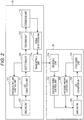
- Fig. 2 is a block diagram of the imaging devices 10 and 20 according to the present embodiment.
- the imaging device 10 will be described with reference to Fig. 2 .
- the imaging device 10 according to the present embodiment mainly includes an imaging unit (first imaging unit) 100, an A/D converter unit 102, a detection unit 104, an exposure amount control unit 106, a tracking unit 108, an estimation unit 110, a signal generation unit 112, and a transmitting unit 114. Details of the functional units of the imaging device 10 will be described below.
- the imaging unit 100 has a function of capturing an object.
- the imaging device 20 as described later is also provided with an imaging unit 200 similar to the imaging unit 100.
- the imaging unit 100 can perform capturing at an imaging frame rate (first frame rate) (e.g., 1000 fps) higher than the frame rate of the imaging unit 200 (second frame rate. More specifically, the imaging unit 100 can capture images at an imaging frame rate of about 100 to 10000 fps.
- the imaging frame rate means the number of imaging frames (still images) per unit time (one second), and is indicated in units of fps (frames per second).
- the imaging unit 100 mainly includes an optical system mechanism including an imaging lens, an aperture mechanism, a zoom lens, a focus lens, etc. (not shown), a solid-state image sensor array 300 (see Fig. 14 ) that photoelectrically converts captured image light obtained by the optical system mechanism to generate an imaging signal, and a drive system mechanism that controls the optical system mechanism (not shown).
- the optical system mechanism concentrates light incident from an object (subject) on the solid-state image sensor array 300 as an optical image, using the lenses.
- the solid-state image sensor array 300 is implemented, for example, by a charge-coupled device (CCD) sensor array, a complementary metal oxide semiconductor (CMOS) sensor array, or the like.
- CMOS complementary metal oxide semiconductor
- the solid-state image sensor array 300 photoelectrically converts a formed optical image pixel by pixel, reads a signal of each pixel as an imaging signal, and outputs it to the A/D converter unit 102 as described later.
- the pixel array in the solid-state image sensor array 300 is not particularly limited. For example, a Bayer array, a BW array (Mono array) entirely constituted of clear pixels, or the like can be selected.
- the drive system mechanism includes a stepping motor or the like that drives the lenses etc.
- the A/D converter unit 102 converts the imaging signal from the solid-state image sensor array 300 of the imaging unit 100 from an analog signal to a digital signal, and outputs it to the detection unit 104 as described later.
- the A/D converter unit 102 is implemented by an electronic circuit, for example.
- the detection unit 104 performs predetermined image processing on the digital signal output from the A/D converter unit 102, and detects the object on the basis of an acquired captured image.
- the detection unit 104 mainly includes hardware such as a central processing unit (CPU), read-only memory (ROM), and random-access memory (RAM) provided in the imaging device 10. Note that details of the detection of the object in the detection unit 104 will be described later.
- the exposure amount control unit 106 detects the brightness of the entire captured image or the object in the captured image, and controls the imaging unit 100 described above so that the brightness of the captured image becomes appropriate, on the basis of the detection result.
- the exposure amount control unit 106 can detect the brightness by detecting the amount of light received at the solid-state image sensor array 300 of the imaging unit 100.
- the exposure amount control unit 106 mainly includes hardware such as a CPU, ROM, and RAM provided in the imaging device 10.
- the tracking unit 108 tracks the object detected by the detection unit 104 described above in a plurality of imaging frames (still images) that have been captured successively at a high speed by the imaging unit 100.
- the tracking unit 108 mainly includes hardware such as a CPU, ROM, and RAM provided in the imaging device 10. Note that details of the tracking of the object in the tracking unit 108 will be described later.
- the estimation unit 110 estimates period information of the flicker phenomenon of the object, on the basis of the plurality of imaging frames of the tracked object.
- the estimation unit 110 mainly includes hardware such as a CPU, ROM, and RAM provided in the imaging device 10. Note that details of the estimation in the estimation unit 110 will be described later.
- the signal generation unit 112 On the basis of the estimation result of the estimation unit 110 described above, the signal generation unit 112 generates a timing signal for capturing the object in the imaging device 20 as described later. In other words, the signal generation unit 112 generates a synchronization signal for the imaging device 20. The timing signal is output to the imaging device 20, and serves as a reference for timing at which the imaging device 20 performs capturing of the object.
- the signal generation unit 112 mainly includes hardware such as a CPU, ROM, and RAM provided in the imaging device 10. Note that details of the generation of the timing signal in the signal generation unit 112 will be described later.
- the transmitting unit 114 is a communication module for transmitting the timing signal etc. to the imaging device 20.
- the transmitting unit 114 establishes synchronization with a receiving unit 214 of the imaging device 20 as described later by transmitting a pulse signal.
- the transmitting unit 114 may establish transmission and reception of the timing signal by time synchronization with the receiving unit 214 of the imaging device 20 as described later, using a technique such as Ethernet AVB (IEEE 802.1 Audio/Video Bridging).
- Ethernet AVB IEEE 802.1 Audio/Video Bridging
- the imaging device 10 may include a positioning unit (not shown) that determines the position of the imaging device 10, or may use sensing date of the positioning unit provided separately from the imaging device 10.
- the positioning unit is implemented, for example, by a global positioning system (GPS) positioning unit, and receives radio waves from GPS satellites to detect the position where the imaging device 10 is located.
- GPS global positioning system
- the positioning unit may be a device that detects the position through, for example, wireless fidelity (Wi-Fi, registered trademark), Bluetooth (registered trademark), transmission and reception to and from mobile phones, personal handy-phone system (PHS), smartphones, etc., short-range communication, or the like.
- the imaging device 10 may further include a storage unit (not shown) that stores captured images captured by the imaging device 10, and programs and parameters for the imaging device 10 to execute the functions.
- the storage unit 122 includes, for example, RAM or the like.
- the imaging device 10 may further include an operation display unit (not shown) that displays a captured image captured by the imaging device 10 for a user, and further accepts input operations of the user.
- the display function of the operation display unit is implemented, for example, by a liquid crystal display (LCD) device or an organic light-emitting diode (OLED) device.
- the operation acceptance function of the operation display unit is implemented, for example, by a touch panel.
- the imaging device 20 mainly includes the imaging unit (second imaging unit) 200, an A/D converter unit 202, an exposure amount control unit 206, the receiving unit 214, a processing unit 216, and an exposure timing control unit 218. Details of the functional units of the imaging device 20 will be described below. Note that in the imaging device 20, the imaging unit 200, the A/D converter unit 202, and the exposure amount control unit 206 are the same as the imaging unit 100, the A/D converter unit 102, and the exposure amount control unit 106 of the imaging device 10, and thus will not be described here.
- the receiving unit 214 is a communication module for receiving the timing signal etc. from the imaging device 10. As described above, the receiving unit 214 establishes synchronization with the transmitting unit 114 by transmitting a pulse signal, for example. Alternatively, the receiving unit 214 may establish transmission and reception of the timing signal through time synchronization with the transmitting unit 114, using a technique such as Ethernet AVB (IEEE 802.1 Audio/Video Bridging).
- Ethernet AVB IEEE 802.1 Audio/Video Bridging
- the processing unit 216 performs various types of signal processing such as white balance adjustment, color correction, edge enhancement, and gamma correction on imaging signals from the A/D converter unit 202 to acquire a captured image. For example, an image of the self-luminous traffic sign 1 is extracted from the captured image acquired by the processing unit 216. By analyzing the extracted image, the sign information of the self-luminous traffic sign 1 can be recognized. Furthermore, the processing unit 216 mainly includes hardware such as a CPU, ROM, and RAM provided in the imaging device 20.
- the exposure timing control unit 218 controls the imaging timing of the imaging unit 200, on the basis of the timing signal from the imaging device 10. For example, the exposure timing control unit 218 detects a difference between the current exposure start timing to acquire an imaging frame and the timing signal, and controls the imaging unit 200 on the basis of the detection result so that the start timing coincides with the timing signal. Furthermore, the exposure timing control unit 218 mainly includes hardware such as a CPU, ROM, and RAM provided in the imaging device 20.
- the solid-state image sensor arrays 300 included in the imaging unit 100 and the imaging unit 200 may be identical to each other in the angle of view and pixel array, or may be different.
- the solid-state image sensor arrays 300 included in the imaging unit 100 and the imaging unit 200 can each be a Bayer array or a BW array.
- the imaging device 20 may further include a storage unit (not shown) that stores captured images captured by the imaging device 10, and programs and parameters for the imaging device 10 to execute the functions, in addition to those described above.
- a storage unit (not shown) that stores captured images captured by the imaging device 10, and programs and parameters for the imaging device 10 to execute the functions, in addition to those described above.
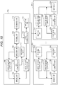
- Fig. 3 is a sequence diagram of the imaging method according to the present embodiment. As shown in Fig. 3 , the imaging method according to the present embodiment includes a plurality of steps from step S100 to step S700. Outlines of the steps included in the imaging method according to the present embodiment will be described below. Note that only the outline of the imaging method according to the present embodiment will be described here, and details of the steps will be described later.
- the imaging device 10 continuously captures an object (e.g., the self-luminous traffic sign 1 or the like) at a high frame rate (e.g., 1000 fps), and detects the object from a plurality of acquired imaging frames.
- a high frame rate e.g. 1000 fps
- the frame rate of the imaging device 10 (high frame rate) (first frame rate) is preferably equal to or higher than a value obtained by multiplying the period of a flicker light source by a numerical value that is twice the inverse of the duty ratio.
- the object can be caught precisely in each imaging frame. For example, in a case where the pulse width is 1 ms and the pulse period is 4 ms in a flicker phenomenon, the duty ratio of the flicker phenomenon is 0.25.
- the high frame rate is preferably set to 2000 fps that is obtained by multiplying four, which is the inverse of the duty ratio of 0.25, by two, and further multiplying the result by a flicker frequency of 250 Hz, or higher. Furthermore, details of the detection of the object will be described later.
- the imaging device 10 performs tracking on the detected object in a plurality of imaging frames acquired successively at the high frame rate. Note that details of the tracking of the object will be described later.
- the imaging device 10 estimates period information (the frequency, lighting time, lighting interval, etc.) of the flicker phenomenon of the object, on the basis of the imaging frames of the object being tracked. Specifically, the imaging device 10 estimates the period information on the basis of changes in the brightness of the object on the plurality of imaging frames. Note that details of the estimation of the period information will be described later.
- the imaging device 10 generates a timing signal that determines the timing to capture the object, on the basis of the estimated period information.
- the imaging device 10 transmits the timing signal to the imaging device 20.
- the imaging device 20 receives the timing signal from the imaging device 10.
- the imaging device 20 controls imaging timing at the imaging unit 200, on the basis of the received timing signal. Moreover, the imaging device 20 can obtain a captured image of the object by processing imaging signals obtained by the imaging unit 200. At this time, the imaging device 20 performs capturing at a low frame rate (second frame rate) (e.g., 30 fps or 60 fps) lower than that of the imaging device 10.
- a low frame rate e.g., 30 fps or 60 fps
- the imaging device 20 captures the object on the basis of the timing signal, and thus can acquire an optimal captured image that can further ensure the recognition of the object.
- the imaging device 20 can capture the object in real time.
- Fig. 4 is an explanatory diagram for explaining the detection of an object according to the present embodiment.
- the example shown in Fig. 4 shows a method of detecting an object to be tracked from a plurality of imaging frames captured at a high frame rate.
- the object is not the self-luminous traffic sign 1 but a human hand.
- the hand is moving slightly in a narrow area for typing on a keyboard.
- the object is not limited to such a human hand, and may be, for example, the self-luminous traffic sign 1 that appears to be moving from a vehicle window, and is not particularly limited.
- captured color imaging frames as shown on the left side of Fig. 4 are subjected to processing under predetermined conditions, to generate gray-scaled imaging frames.
- the red (R) pixel value (color information) of each pixel in a color imaging frame is extracted.
- the R pixel value of each pixel of the gray-scaled imaging frame is compared with a predetermined threshold value.
- the pixel value of a pixel equal to or higher than the predetermined threshold value is converted to one, and the pixel value of a pixel less than the predetermined threshold value is converted to zero. This can generate a binarized imaging frame as shown in the center of Fig. 4 .
- the element value of one of red, green, and blue (RGB) may be extracted, or a mean value of the three element values may be used, or a value obtained by integrating the element values after the element values are weighted may be used.
- RGB red, green, and blue
- the person can be detected on the basis of the person's skin color. Specifically, by extracting only pixels whose element values of the three colors satisfy the following relational expression (1), pixels corresponding to human skin color are extracted. Then, a person can be detected on the basis of the skin color extraction result.
- Equation 1 R > G ⁇ 1 + ⁇ R > B ⁇ 1 + ⁇ ⁇ MAX > R > ⁇ MIN
- R, G, and B represent the element values of the colors.
- yMAX and ⁇ MIN represent the maximum value and the minimum value of the element value of each color.
- ⁇ , ⁇ , ⁇ MAX, and ⁇ MIN are coefficients that the user can set as desired.
- the detection of skin color may be performed, for example, by processing the three element values of each pixel in a color imaging frame using a predetermined mathematical formula, calculating an index value on each pixel, and extracting only pixels whose calculated index values are within a predetermined range.
- the three element values of each pixel may be converted to an index value based on an HSV model expressed by hue, saturation, and brightness.
- a plurality of binarized imaging frames shown in the upper and middle rows of the central column of Fig. 4 are compared, and a difference between the imaging frames is extracted, so that a specific area (target) caused by motion is extracted as shown in the lower row of the central column of Fig. 4 .
- the detection of the object is not limited to the above-described method.
- characteristic points of the object may be stored in advance, and detection of the object may be performed by extracting the stored characteristic points from an imaging frame.
- the object in a case where the object is a person's face, the person is detected on the basis of characteristic points (the eyes, nose, and mouth) of the person's face.
- the imaging device 10 is provided with the positioning unit (not shown) that detects the position of the imaging device 10, the object may be detected on the basis of sensing data of the positioning unit.
- the imaging device 10 is mounted on a vehicle, and the object is a traffic light
- a captured image of the traffic light will appear in an area fixed to the imaging device 10 (vehicle) (e.g., a left front area of the vehicle). That is, the traffic light will be present in an area fixed with respect to the angle of view of the imaging device 10. Therefore, by referring to map information including position information of the traffic light stored in advance and the sensing data of the positioning unit, the imaging device 10 can recognize the position where the traffic light will appear in advance, and thus can detect the traffic light on the basis of the recognition result.
- the detection of the object is not limited to the above-described method.
- the detection of the object may be performed by displaying an imaging frame captured first to the user, and the user selecting a desired object in the imaging frame.
- step S200 as shown on the right side of Fig. 4 , tracking is performed on the object (the hand in Fig. 4 ) detected in step S100 described above.
- self windowing is used to keep track of the object in a plurality of successive imaging frames captured at the high frame rate.
- self windowing is a type of algorithm for tracking an object in imaging frames captured at a high frame rate.
- the moving distance (difference) of the object in a plurality of imaging frames is small. Therefore, in a case where an extraction window for extracting the object has been set in an area around the object in the previous imaging frame, the object will be included in the extraction window also in the next imaging frame. More specifically, the extraction window is set as a pixel area that is expanded outward by one pixel with respect to a pixel area showing the object in the previous imaging frame. If the object is not included in the set extraction window in the next imaging frame rate, by setting the frame rate higher, the object can be included in the extraction window.
- the extraction window has been described as being set as the pixel area expanded outward by one pixel with respect to the pixel area showing the object in the previous imaging frame in the above description, the present embodiment is not limited to the expansion by one pixel.
- a pixel area expanded by two or more pixels may be set as the extraction window.
- the number of pixels by which the pixel area is expanded can be suitably selected according to the frame rate and the speed of the object, or the like, for example.
- the present embodiment is not limited to such a method.
- the number of pixels by which the pixel area is expanded may be adjusted when an extraction window is set so that the object is included in the extraction window.
- self windowing calculates a logical product between the extraction window calculated from the previous imaging frame and the next binarized object image, thereby generating a target extraction image and tracking the object. Furthermore, according to self windowing, images of the object are compared between target extraction images of two successive imaging frames, so that not only the position information and area (shape) information of the object but also information such as the moving direction and moving speed of the object can be acquired. As is clear from the above description, in a case where self windowing is used, it is preferable that imaging frames used for tracking an object are captured at a high frame rate.
- tracking of an object is not limited to the above-described example, and another method may be used.
- tracking of an object may be performed on the basis of characteristic points that two successive imaging frames have in common.
- the mean value of the brightness of an image of the tracked object is stored for each of a plurality of imaging frames, and by using the discrete Fourier transform (DFT) on the stored data, period information of the flicker phenomenon such as the frequency, the width of the lighting time, and the lighting interval is estimated.
- DFT discrete Fourier transform
- the brightness of the object in a plurality of imaging frames should change according to the period of the flicker phenomenon. Therefore, in the present embodiment, the mean value of the brightness of a plurality of pixels corresponding to an image of the object is acquired for each of a plurality of imaging frames acquired at a predetermined frame rate, and by applying the DFT, changes over time in brightness, that is, a frequency component (frequency, lighting time width, lighting interval, etc.) in changes over time in brightness is estimated. Note that since the imaging frames used for estimating the period information are acquired at a frame rate higher than the period of the flicker phenomenon, the period information of the flicker phenomenon can be estimated by applying the DFT.
- the estimation of the period information is not limited to the above-described example, and another method may be used.
- the period information may be estimated by analyzing a plurality of imaging frames in a predetermined period, and counting the number of imaging frames in which the light of the object is turned on and the number of imaging frames in which the light of the object is turned off.
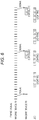
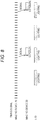
- Figs. 5 to 8 are explanatory diagrams for explaining examples of the timing signal according to the present embodiment. Note that in Figs. 5 to 8 , imaging timing at the imaging device 10 is indicated by vertical lines in the upper row. Further, in the middle row, the timing signal transmitted from the imaging device 10 to the imaging device 20 is indicated by vertical lines, and the exposure time at the imaging device 20 is indicated by bands extending in the horizontal direction. In addition, in the lower row, the lighting time of the LEDs as the object is indicated by bands extending in the horizontal direction.
- the signal generation unit 112 generates a signal to control the timing of exposure start at the imaging device 20 or a timing signal to control the timing of exposure end, on the basis of the period information estimated in step S300 described above. Regardless of which signal is generated, the generated timing signal satisfies the following conditions. Specifically, in the present embodiment, the frequency of the timing signal is set such that the imaging frame rate of the imaging device 10 (high frame rate) is an integral multiple of the imaging frame rate of the imaging device 20 (low frame rate). Moreover, the frequency of the timing signal is set such that the frequency of the flicker phenomenon (the frequency of blinking of the LEDs) is an integral multiple of the imaging frame rate of the imaging device 20.
- Fig. 5 shows a case where the timing signal to control the timing of exposure end at the imaging device 20 is generated, and further, a case where the frequency of the flicker phenomenon (the frequency of blinking of the LEDs) is equal to the frame rate of the imaging device 20. That is, in the example shown in Fig. 5 , the imaging device 20 is controlled to end exposure upon receiving the timing signal.
- the imaging frame rate of the imaging device 10 is 1200 fps
- the imaging frame rate of the imaging device 20 is 120 fps
- the frequency of blinking of the LEDs is 120 Hz.
- Fig. 6 shows a case where the timing signal to control the timing of exposure end at the imaging device 20 is generated, and further, a case where the frequency of the flicker phenomenon (the frequency of blinking of the LEDs) is twice the imaging frame rate of the imaging device 20.
- the frequency of the flicker phenomenon the frequency of blinking of the LEDs
- the imaging frame rate of the imaging device 10 is 1200 fps
- the imaging frame rate of the imaging device 20 is 60 fps
- the frequency of blinking of the LEDs is 120 Hz.
- Fig. 7 shows a case where the timing signal to control the timing of exposure start at the imaging device 20 is generated, and further, a case where the frequency of the flicker phenomenon (the frequency of blinking of the LEDs) is equal to the frame rate of the imaging device 20. That is, in the example shown in Fig. 7 , the imaging device 20 is controlled to start exposure upon receiving the timing signal.
- the imaging frame rate of the imaging device 10 is 1200 fps
- the imaging frame rate of the imaging device 20 is 120 fps
- the frequency of blinking of the LEDs is 120 Hz.
- Fig. 8 shows a case where the timing signal to control the timing of exposure start at the imaging device 20 is generated, and further, a case where the frequency of the flicker phenomenon (the frequency of blinking of the LEDs) is twice the imaging frame rate of the imaging device 20.
- the frequency of the flicker phenomenon the frequency of blinking of the LEDs
- the imaging frame rate of the imaging device 10 is 1200 fps
- the imaging frame rate of the imaging device 20 is 60 fps
- the frequency of blinking of the LEDs is 120 Hz.
- the frequency of the timing signal is set to a value obtained by multiplying the period of the flicker light source by the inverse of the duty ratio, or higher.
- the timing signal generated is not limited to the signal shown in Figs. 5 to 8 .
- the timing signal is not particularly limited as long as it is a signal that can control the imaging device 20 so that the exposure period of the imaging device 20 can be made coincident with at least part of the LED lighting period.
- the period of the flicker phenomenon (the frequency of blinking of the LEDs) and the imaging frame rate of the imaging device 20 may not be in an integer multiple relationship due to minute errors. In that case, the period shifts as time passes, and the imaging device 20 may not be able to capture the object being lit. Therefore, in the present embodiment, by estimating the period information of the flicker phenomenon once every few times, preferably every time, and generating the timing signal on the basis of the estimation result, a period shift as described above can be avoided.
- the imaging unit 200 of the imaging device 20 preferably uses global shutter, that is, simultaneous exposure all-at-once readout, but may use rolling shutter, that is, line exposure sequential readout.
- global shutter refers to control in which the pixels 302 (see Fig. 14 ) of the solid-state image sensor array 300 of the imaging unit 200 are exposed simultaneously and read simultaneously.
- rolling shutter refers to control in which the pixels 302 of the solid-state image sensor array 300 of the imaging unit 200 are sequentially exposed and read line by line.
- the imaging unit 200 of the imaging device 20 uses rolling shutter, by generating a timing signal that takes into account a shift in exposure time/readout time of each line, the lit object being lit can be imaged.
- the object being lit can be imaged.
- the imaging device 20 by tracking the object, changes in the brightness of the object in a plurality of imaging frames are detected, and from the detected changes in the brightness, the period information of the flicker phenomenon (blinking) of the object is estimated.
- changes in the brightness of the object can be captured with high accuracy, and further, the period information can be estimated with high accuracy.
- the timing signal for capturing the object by generating the timing signal for capturing the object appropriately on the basis of the estimated period information, an optimal captured image that can further ensure the recognition of the object can be acquired.
- the imaging device 20 since the period information is estimated quickly using imaging frames obtained at the high frame rate to generate the timing signal, the imaging device 20 can capture the object in real time.
- the imaging devices 10 and 20 according to the present embodiment are mounted on a vehicle, and capture the self-luminous traffic sign 1, the imaging device 20 can capture the self-luminous traffic sign 1 in a lit state, and thus can ensure that the sign information (speed limit) of the self-luminous traffic sign 1 is recognized.
- a driving safety support system that supports a driver's driving, and further automatic driving, using captured images can be constructed.
- the present embodiment is not limited to capturing the above-described self-luminous traffic sign 1 with the imaging device 20 mounted on the vehicle, and can capture buildings and illuminations having a blinking lighting device or the like, present around the vehicle traveling. Furthermore, as will be described later, the present embodiment can also be used for capturing a plurality of objects having different blinking periods. In this case, a plurality of objects in a blinking state can be imaged simultaneously, or can be imaged with some objects excluded.
- the present embodiment can also be applied to capturing under a fluorescent light.
- Fig. 9 which is an explanatory diagram for explaining an example of an imaging scene in the present embodiment
- the present embodiment can also be applied to an imaging device that captures an athlete 90 under a lighting device 80 that is blinking due to a flicker phenomenon, indoors, such as in a gymnasium 3.
- the athlete 90 lit up by the lighting device 80 having the flicker phenomenon such as a fluorescent light is playing a sport such as basketball in which he or she moves quickly, the motion of the athlete 90 can be imaged.
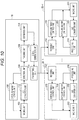
- Fig. 10 is a block diagram of the imaging devices 10 and 20 according to the first modification of the present embodiment.
- Fig. 11 is an explanatory diagram for explaining an example of timing signals according to the first modification of the present embodiment. Note that in Fig. 11 , imaging timing at the imaging device 10 is indicated by vertical lines in the upper row.
- timing signals transmitted from the imaging device 10 to an imaging device 20-1 and an imaging device 20-n are indicated by vertical lines, and exposure times at the imaging devices 20-1 and 20-n are indicated by bands extending in the horizontal direction.
- the lighting time of LEDs (1) that are an object of the imaging device 20-1 and the lighting time of LEDs (n) that are an object of the imaging device 20-n are indicated by bands extending in the horizontal direction.
- a plurality (n) of the imaging devices 20 described above is provided. Furthermore, in the present modification, the imaging device 10 including the detection unit 104, the tracking unit 108, and the estimation unit 110 detects and tracks a plurality of objects, and estimates period information of the flicker phenomenon of each object. Moreover, the signal generation unit 112 of the imaging device 10 generates a plurality of timing signals for capturing the objects, on the basis of the estimated period information. Then, the plurality of timing signals generated by the imaging device 10 is transmitted to the plurality of corresponding imaging devices 20, and the imaging devices 20 capture the corresponding objects. Therefore, for example, in a case where the period information pieces of the flicker phenomenon of the objects are different from each other, the imaging device 10 generates a plurality of timing signals having different periods.
- the imaging device 10 transmits timing signals having different periods to the imaging device 20-1 and the imaging device 20-n.
- the imaging device 10 generates timing signals to control the timings of exposure end at the imaging devices 20-1 and 20-n.
- the imaging devices 20-1 and 20-n perform exposure in accordance with the blinking periods, so that the LEDs (1) and the LEDs (n) in a lit state can be imaged.
- the imaging devices 20-1 and 20-n perform exposure in accordance with the blinking periods, so that the LEDs (1) and the LEDs (n) in a lit state can be imaged.
- the imaging frame rate of the imaging device 10 is 1200 fps
- the imaging frame rates of the imaging device 20-1 and the imaging device 20-n are 100 fps
- the imaging devices 20-1 and 20 -n perform exposure at different timings.
- the LEDs (1) and the LEDs (n) have a blinking frequency of 100 Hz, for example, they are lit at different timings in this example.
- the imaging devices 20 can be controlled to capture only a specific object, on the basis of the estimated period information.
- the imaging device 10 estimates the period information of blinking of the two illuminations, calculates a period for capturing only one illumination, and controls the imaging devices 20 on the basis of the calculation result.
- the imaging device 10 transmits timing signals to simultaneously expose the two imaging devices 20 to them. Furthermore, in such a case, for example, the control timing of a millimeter-wave radar 50 (see Fig. 16 ) provided on the vehicle may be accurately synchronized with the timing when the two imaging devices 20 capture images. This can further improve object recognition accuracy.
- the imaging device 10 generates and transmits the timing signal to control the exposure timing of the imaging device 20.
- the imaging device 10 may transmit not only the timing signal to control the exposure timing of the imaging device 20, but also a signal to control the aperture and shutter speed of the imaging unit 200 of the imaging device 20. Details of the present modification will be described below with reference to Fig. 12.
- Fig. 12 is a block diagram of imaging devices 10a and 20a according to the modification of the present embodiment.
- the imaging device 10a according to the present modification mainly includes the imaging unit 100, the A/D converter unit 102, the detection unit 104, an exposure amount control unit 106a, the tracking unit 108, the estimation unit 110, the signal generation unit 112, and the transmitting unit 114.
- the imaging unit 100, the A/D converter unit 102, the detection unit 104, the tracking unit 108, the estimation unit 110, the signal generation unit 112, and the transmitting unit 114 are the same as those of the above-described imaging device 10, and thus will not be described, and only the exposure amount control unit 106a will be described.
- the exposure amount control unit 106a detects the brightness of the object in a captured image, and on the basis of the detection result, controls the exposure amount of the imaging unit 100 described above, that is, the aperture, shutter time, etc. so that the brightness of the object in a captured image becomes appropriate. Moreover, the exposure amount control unit 106a generates an exposure control signal to control the exposure amount of the imaging unit 200 of the imaging device 20a as with the imaging unit 100, and outputs the generated exposure control signal to the transmitting unit 114.
- the imaging device 20a according to the present modification mainly includes the imaging unit 200, the A/D converter unit 202, the exposure amount control unit 206, a receiving unit 214a, the processing unit 216, and the exposure timing control unit 218.
- the imaging unit 200, the A/D converter unit 202, the exposure amount control unit 206, the processing unit 216, and the exposure timing control unit 218 are the same as those of the above-described imaging device 20, and thus will not be described, and only the receiving unit 214a will be described.
- the receiving unit 214a not only outputs the timing signal from the imaging device 10a to the exposure timing control unit 218, but also outputs the exposure control signal from the imaging device 10a to the exposure amount control unit 206.
- the calculation of the exposure amount at the imaging device 20 is performed at the imaging device 10, and thus the calculation of the exposure amount at the imaging device 20 becomes unnecessary. Therefore, according to the present modification, the imaging device 20 can be made compact, and power consumption in the imaging device 20 can be reduced.
- the imaging devices 10 and 20 are used for implementation.
- the present embodiment is not limited to implementation with two or more imaging devices, and may be implemented with one imaging device.
- a second embodiment of the present disclosure using one imaging device 10b will be described.
- Fig. 13 is a block diagram of the imaging device 10b according to the present embodiment.
- Fig. 14 is an explanatory diagram for explaining array examples of a solid-state image sensor array 300 of an imaging unit 100b according to the present embodiment. Note that in Fig. 14 , R indicates a pixel that detects red, G indicates a pixel that detects green, and B indicates a pixel that detects blue.
- the imaging device 10b mainly includes the imaging unit 100b, the A/D converter unit 102, the detection unit 104, the exposure amount control unit 106, the tracking unit 108, the estimation unit 110, the signal generation unit 112, the processing unit 116, and the exposure timing control unit 118.
- the functional units are the same as the functional units having the same names of the imaging devices 10 and 20 according to the first embodiment described above, and thus the description of the functional units is omitted here.
- the solid-state image sensor array 300 is provided with a pixel group that captures images at a high frame rate (short-time exposure pixel group) (first imaging element group) 302a, and a pixel group that captures images at a low frame rate (long-time exposure pixel group) (second imaging element group) 302b, so that the functions of the imaging devices 10 and 20 can be implemented by the single imaging device 10b.
- the pixels 302a that capture images at the high frame rate like those of the imaging device 10 and the pixels 302b that capture images at the low frame rate like those of the imaging device 20 are present.
- the pixels 302a and the pixels 302b function like those of the imaging device 10 and the imaging device 20 according to the first embodiment described above, respectively, thereby enabling implementation with the single imaging device 10b.
- Fig. 14 an example is shown in which the pixels 302a for the high frame rate and the pixels 302b for the low frame rate are alternately provided in two rows. Also, on the right side of Fig. 14 , an example is shown in which the pixels 302a for the high frame rate and the pixels 302b for the low frame rate are randomly provided.
- Fig. 14 show RGB pixel arrays, each may be replaced with a BW array in the present embodiment. In this case, pixels 302 replaced with those of the BW array may be the pixels 302a for the high frame rate, or may be the pixels 302b for the low frame rate, or may be both the pixels 302.
- the solid-state image sensor array 300 according to the present embodiment is not limited to the examples shown in Fig. 14 . Various arrays can be used as long as the two types of pixels 302a and 302b are included.
- the pixels 302a for the high frame rate of the solid-state image sensor array 300 in the pixel array as described above function similarly to those of the imaging unit 100 of the imaging device 10 in the first embodiment. That is, the imaging device 10b generates imaging frames on the basis of image signals acquired by the pixels 302a for the high frame rate, performs detection and tracking of the object, estimates period information of the flicker phenomenon, and generates a timing signal. Furthermore, the pixels 302b for the low frame rate of the solid-state image sensor array 300 are controlled by the above-described timing signal to capture images, and thus can capture the object being lit similar to the imaging unit 200 of the imaging device 20 in the first embodiment.
- a final captured image of the object that is, an image of the object captured by the imaging device 20 in the first embodiment is generated using image signals acquired by the pixels 302b for the low frame rate.
- the captured image may be generated using image signals of both the pixels 302a for the high frame rate and the pixels 302b for the low frame rate.
- the obtained final captured image of the object is a high dynamic range (HDR) captured image having a wide contrast.
- HDR high dynamic range
- the imaging device 10b by providing the pixels 302a for the high frame rate and the pixels 302b for the low frame rate in the single solid-state image sensor array 300, the imaging device 10b, even singly, can capture the object being lit.
- Fig. 15 is a block diagram of the imaging devices 10b and 20 according to the modification of the present embodiment.
- the imaging device 10b is configured similarly to the imaging device 10b according to the second embodiment. Moreover, in the present modification, a plurality (n) of the imaging devices 20 according to the first embodiment is provided. Specifically, the imaging device 10b including the detection unit 104, the tracking unit 108, the estimation unit 110, and the signal generation unit 112 detects and tracks objects, estimates period information, and generates timing signals on the basis of the estimation results. Then, the timing signals generated at the imaging device 10b are transmitted to the corresponding imaging devices 20 and 20-n.
- final captured images of the plurality of objects are acquired at the imaging device 10b and the imaging devices 20-1 to 20-n.
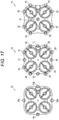
- FIGS. 16 and 17 are explanatory diagrams illustrating mounting examples of the imaging devices according to the third embodiment of the present disclosure.
- the imaging devices 10 and 20 according to the present embodiment are mounted on a passenger vehicle 2
- the imaging device 10 according to the present embodiment is provided at the upper center of the windshield of the passenger vehicle 2
- the two imaging devices 20 according to the present embodiment are provided on opposite sides of the imaging device 10.
- the passenger vehicle 2 is provided with a positioning sensor 30, an acceleration sensor 40, the millimeter-wave radar 50, an illuminance sensor 60, etc.
- the acceleration sensor 40 detects acceleration produced by the movement of the passenger vehicle 2.
- the millimeter-wave radar 50 radiates millimeter waves (e.g., radio waves having a wavelength of about 1 to 10 mm) around the vehicle, and detects reflected waves to detect, for example, a distance to an object around the passenger vehicle 2, or the like.
- the illuminance sensor 60 detects the brightness of the outside of the passenger vehicle 2.
- the imaging device 10 detects a coped object, performs tracking, and further estimates period information of a flicker phenomenon, generates timing signals, and transmits the timing signals to the two imaging devices 20.
- These two imaging devices 20 receive the timing signals, and capture the object on the basis of the received timing signals.
- the timing signals are signals having different periods.
- the two imaging devices 20 measure the distance to one object, they are timing signals (synchronization signals) that allow the two imaging devices 20 to simultaneously capture the object.
- capturing at the imaging devices 20 may be controlled using sensing data of the positioning sensor 30, the acceleration sensor 40, the millimeter-wave radar 50, the illuminance sensor 60, etc. as necessary.
- the imaging devices 10 and 20 are provided at an upper part of the windshield of the passenger vehicle 2. However, in the present embodiment, they are not limited to being installed at such positions, and may be provided on the back side or the left and right sides of the passenger vehicle 2. For example, in a case where the imaging devices 10 and 20 are provided on the back side of the passenger vehicle 2, these imaging devices 10 and 20 can function as a monitoring system that captures the back of the passenger vehicle 2 in place of the rearview mirror, and can support the driver's driving.
- the imaging devices 10, 10b, and 20 according to the present embodiment are mounted on a drone 70.
- the drone 70 is a small aircraft, and refers to an apparatus that has an autonomous flight function, an autonomous attitude control function, and the like without an operator on board because of its structure, and can fly in a three-dimensional space.
- the drone 70 is shown on which four imaging devices 10b according to the second embodiment are mounted.
- the drone 70 is shown on which four imaging devices 10 according to the first embodiment and eight imaging devices 20 according to the same embodiment are mounted.
- the drone 70 is shown on which one imaging device 10 according to the first embodiment and eight imaging devices 20 according to the same embodiment are mounted.
- the imaging devices 10b are provided at the centers of the sides of the drone 70, and objects located in different directions as viewed from the drone 70 can be imaged by the imaging devices 10b.
- the imaging devices 10 each have a wide-angle imaging unit 100 having an angle of view of nearly 180 degrees, and are provided at the centers of the sides of the drone 70. Moreover, each imaging device 10 controls a pair of imaging devices 20 positioned on the opposite sides of the imaging device 10. For example, the pair of imaging devices 20 are controlled by the imaging device 10 to be synchronized with each other, and can perform measurement of distance to an object.
- the imaging device 10 has a wide-angle imaging unit 100 having an angle of view of nearly 360 degrees, and is provided at the top center of the drone 70. Moreover, the imaging device 10 controls the eight imaging devices 20 positioned around the imaging device 10.
- the imaging device can be mounted, as a device for monitoring surroundings, on a spatially movable apparatus such as the passenger vehicle 2, the drone 70, or an industrial or home robot that is remotely operated by an operator or can move autonomously.
- the imaging device is not limited to being limited to being mounted on such an apparatus, and for example, because of its capability of high-speed capturing, may be mounted on an analysis apparatus capable of analyzing an object such as analyzing a phenomenon varying at high speed that is difficult to observe with human eyes. More specifically, examples of the analysis apparatus include measurement devices used for analysis of an object drop or impact test, an explosion test, or the like, analysis of an athlete's motion, and the like.
- changes in the brightness of an object in a plurality of imaging frames are detected by tracking the object, and period information of a flicker phenomenon (blinking) of the object is estimated on the basis of the detected changes in the brightness.
- the period information can be estimated with high accuracy.
- a timing signal for capturing the object appropriately is generated on the basis of the estimated period information, and the object is imaged on the basis of the timing signal, so that an optimal captured image that can further ensure the recognition of the object can be acquired.
- the imaging device 20 can capture the object in real time.
- steps in the imaging method of the above-described embodiments do not necessarily have to be processed in the described order.
- the steps may be processed in an appropriately changed order.
- the steps may be processed partly in parallel or individually, instead of being processed in time series.
- the processing in the steps does not necessarily have to be processed in accordance with the described method, and may be processed by other methods by other functional blocks, for example.
- the effects described in the present description are merely illustrative or exemplary and are not limiting. That is, the technique according to the present disclosure can achieve other effects that are obvious to those skilled in the art from the description of the present description in addition to the above effects, or in place of the above effects.
Landscapes
- Engineering & Computer Science (AREA)
- Multimedia (AREA)
- Signal Processing (AREA)
- Physics & Mathematics (AREA)
- General Physics & Mathematics (AREA)
- Theoretical Computer Science (AREA)
- Computer Vision & Pattern Recognition (AREA)
- Mechanical Engineering (AREA)
- Human Computer Interaction (AREA)
- Studio Devices (AREA)
- Traffic Control Systems (AREA)
- Transforming Light Signals Into Electric Signals (AREA)
Abstract
Description
- The present disclosure relates to an imaging device and an apparatus.
- In recent years, to provide secure and safe automobiles, the development of driving safety support systems that support drivers' driving and automatic driving has been promoted. In such development, it is required to recognize various objects such as traffic signs, vehicles, and passers-by present around a vehicle with a vehicle-mounted imaging device or the like. For example, one of the objects to be recognized may be a self-luminous traffic sign using light emitting diodes (LEDs).
- By the way, LEDs have periodic flicker, though to an extent not perceived by humans, due to the frequency of an AC source that supplies power to the LEDs, or the like. Such flicker is called a flicker phenomenon. An example of an imaging device that captures an object having such a flicker phenomenon is disclosed in
Patent Document 1 below. - Furthermore, when the self-luminous traffic sign is imaged by the vehicle-mounted imaging device, the self-luminous traffic sign may be imaged at the moment when the LEDs are turned off due to the flicker phenomenon, and the information of the sign indicated by the LEDs of the self-luminous traffic sign may not be able to be recognized from the obtained captured image. Thus, as a measure against the above-described phenomenon, a method is conceivable by which to increase the exposure time of the imaging device to an integral multiple of the period of the flicker phenomenon of the LEDs to ensure capturing of the LEDs when the LEDs are being lit.
- Patent Document 1: Japanese Patent Application Laid-Open No.
2008-211442 - However, in a case where the exposure time is increased to an integral multiple of the period of the flicker phenomenon of the LEDs in the vehicle-mounted imaging device, a motion blur may occur on a captured image (also called a "subject blur") or saturation (also called a "whiteout") may occur, and thus an appropriate captured image that allows recognition of the sign information may not be able to be obtained.
- Therefore, in view of the above circumstances, the present disclosure proposes a new and improved imaging device and apparatus that can obtain an appropriate captured image that allows recognition of an object even when a flicker phenomenon is occurring.
- According to the present disclosure, provided is an imaging device including a detection unit that detects a blinking object or an object lit by a blinking illuminator, a tracking unit that performs tracking on the detected object, an estimation unit that estimates period information of the blinking, on the basis of a plurality of imaging frames of the tracked object, and a signal generation unit that generates a timing signal for capturing the object, on the basis of the estimation result.
- Further, according to the present disclosure, provided is an apparatus that is spatially movable or can analyze a blinking object or an object lit by a blinking illuminator, and is equipped with an imaging device including a detection unit that detects the object, a tracking unit that performs tracking on the detected object, an estimation unit that estimates period information of the blinking, on the basis of a plurality of imaging frames of the tracked object, and a signal generation unit that generates a timing signal for capturing the object, on the basis of an estimation result.
- As described above, according to the present disclosure, it is possible to provide an imaging device and an apparatus that can obtain an appropriate captured image that allows recognition of an object even when a flicker phenomenon is occurring.
- Note that the above effects are not necessarily limiting, and any of the effects described in the present description, or other effects that can be understood from the present description may be achieved together with the above effects or in place of the above effects.
-
-
Fig. 1 is an explanatory diagram for explaining the background of the present disclosure. -
Fig. 2 is a block diagram ofimaging devices -
Fig. 3 is a sequence diagram of an imaging method according to the embodiment. -
Fig. 4 is an explanatory diagram for explaining detection of an object according to the embodiment. -
Fig. 5 is an explanatory diagram (the first one) for explaining an example of a timing signal according to the embodiment. -
Fig. 6 is an explanatory diagram (the second one) for explaining an example of a timing signal according to the embodiment. -
Fig. 7 is an explanatory diagram (the third one) for explaining an example of a timing signal according to the embodiment. -
Fig. 8 is an explanatory diagram (the fourth one) for explaining an example of a timing signal according to the embodiment. -
Fig. 9 is an explanatory diagram for explaining an example of an imaging scene in the embodiment. -
Fig. 10 is a block diagram of theimaging devices -
Fig. 11 is an explanatory diagram for explaining an example of timing signals according to the first modification of the embodiment. -
Fig. 12 is a block diagram ofimaging devices -
Fig. 13 is a block diagram of animaging device 10b according to a second embodiment of the present disclosure. -
Fig. 14 is an explanatory diagram for explaining array examples of a solid-stateimage sensor array 300 of animaging unit 100b according to the embodiment. -
Fig. 15 is a block diagram of theimaging devices -
Fig. 16 is an explanatory diagram (the first one) illustrating an example of mounting of the imaging devices according to a third embodiment of the present disclosure. -
Fig. 17 is an explanatory diagram (the second one) illustrating examples of mounting of the imaging devices according to the embodiment. - Hereinafter, preferred embodiments of the present disclosure will be described in detail with reference to the accompanying drawings. Note that in the description and drawings, the same reference numerals are assigned to components having substantially the same functional configurations, to avoid duplicated explanation.
- Furthermore, in the description and drawings, there are cases where a plurality of components having substantially the same or similar functional configuration is distinguished by adding different numerals to the end of the same reference numeral. However, in a case where it is not necessary to particularly distinguish a plurality of components having substantially the same or similar functional configuration from each other, only the same reference numeral is assigned. Furthermore, there are cases where similar components in different embodiments are distinguished by adding different alphabets to the end of the same reference numeral. However, in a case where it is not necessary to particularly distinguish similar components from each other, only the same reference numeral is assigned.
- Note that the description will be made in the following order.
- 1. Background that has caused inventors to create embodiments of present disclosure
- 2. First embodiment
- 2.1 Configuration of imaging device
- 2.2 Outline of imaging method
- 2.3 Detection of object (step S100)
- 2.4 Tracking of object (step S200)
- 2.5 Estimation of period information (step S300)
- 2.6 Generation of timing signal (step S400)
- 2.7 First modification
- 2.8 Second modification
- 3. Second embodiment
- 3.1 Configuration of imaging device
- 3.2 Third modification
- 4. Third embodiment
- 5. Summary
- 6. Supplement
- First, before describing embodiments of the present disclosure, the background that has caused the inventors to create the embodiments of the present disclosure will be described.
- In recent years, to provide secure and safe automobiles, the development of driving safety support systems that support drivers' driving and automatic driving has been promoted. In such development, it is required to recognize various objects such as traffic signs present around a vehicle with a vehicle-mounted imaging device or the like. For example, one of the objects to be recognized may be a self-
luminous traffic sign 1 using LEDs as shown inFig. 1 , which is an explanatory diagram for explaining the background of the present disclosure. Such a self-luminous traffic sign 1 can display, for example, a number corresponding to a speed limit through the light emission of the LEDs, and thus allows drivers to easily visually recognize the speed limit even under poor visibility conditions such as at night. - However, the LEDs of the self-
luminous traffic sign 1 have periodic flicker (a flicker phenomenon), though to an extent not perceived by humans, due to the frequency of an AC source that supplies power to the LEDs, the frequency of a power source controlled by a controller that adjusts the intensity of the LEDs, or the like. The period of the flicker phenomenon of the LEDs depends on the frequency of the AC source supplied or a frequency set by a contractor who installs traffic signs or a manager, with visibility taken into account. Therefore, in a large number of self-luminous traffic signs 1 installed on roads and the like nationwide, the periods of the flicker phenomenon of the LEDs are not uniform. - Further, when the self-
luminous traffic sign 1 is imaged by the vehicle-mounted imaging device, the self-luminous traffic sign 1 may be imaged at the moment when the LEDs are turned off due to the flicker phenomenon, and thus the sign information (e.g., a speed limit) indicated by the self-luminous traffic sign 1 may not be able to be recognized from the captured image. For example, the LEDs of the self-luminous traffic sign 1 generally have a flicker frequency of 100 to 250 Hz. However, in order to establish secure and safe automobile driving, it is required to avoid a situation where the sign information of the self-luminous traffic sign 1 cannot be recognized due to the flicker phenomenon, in the vehicle-mounted imaging device. - Then, as a measure against this, it is conceivable to construct a system that notifies vehicles of traffic regulations and the like by radio signals. However, in this case, such a system will be constructed over the nationwide road network, and thus the cost of the system construction will be enormous. Thus, it is not a realistic measure.
- Furthermore,
Patent Document 1 described above discloses an example of an imaging device that captures an object (a traffic light) having a flicker phenomenon. The imaging device ofPatent Document 1 measures the blinking period of the traffic light, compares the measured period with a threshold value to determine whether the traffic light is in an intended blinking state or is in a blinking state due to the flicker phenomenon, and selects a captured image to be stored on the basis of the determination result. That is,Patent Document 1 described above determines only the blinking state of the traffic light, and merely selects a representative image showing the state of the traffic light according to the blinking state, and is not a technique for acquiring an appropriate captured image that allows recognition of details of the object (e.g., details of information indicated by the object). - Furthermore, as a measure against the flicker phenomenon taken by the imaging device, a method is conceivable by which to increase the exposure time of the imaging device to an integral multiple of the period of the flicker phenomenon to capture the object when the object is being lit. However, in a case where such a measure is used in the vehicle-mounted imaging device, a captured image may be saturated (also called a "whiteout") due to the increased exposure time. Further, the vehicle on which the imaging device is mounted moves during the long exposure time, and thus a motion blur may occur on a captured image (also called a "subject blur"). On such a captured image, an image of the captured object is unclear, and thus it is difficult to recognize details of the object (e.g., details of information indicated by the object). That is, in such a case, it is difficult to recognize, for example, the sign information, and thus it is difficult to establish secure and safe automobile driving through recognition based on a captured image.
- Therefore, in view of the above circumstances, the present inventors have come to create the embodiments of the present disclosure that can provide an appropriate captured image that allows recognition of an object even when a flicker phenomenon is occurring. For example, according to the embodiments of the present disclosure described below, even for the self-
luminous traffic sign 1 having the flicker phenomenon, for example, a captured image that allows recognition of the sign information indicated by the self-light-emittingtraffic sign 1 can be obtained. As a result, secure and safe automobile driving can be established by using the recognized sign information. Hereinafter, details of the embodiments of the present disclosure as described above will be sequentially described in detail. - In the following description, the embodiments of the present disclosure will be described using an example where they are applied to an imaging device for acquiring a captured image of an object that performs display through the light emission of LEDs or the like. However, the embodiments of the present disclosure are not limited to being applied to imaging devices as described above. For example, the embodiments of the present disclosure may be applied to an imaging device used for capturing images under a lighting device
- (illuminator) such as a fluorescent lamp (with a flicker frequency of 100 Hz or 120 Hz).
- In a first embodiment of the present disclosure described below, two or
more imaging devices imaging devices Fig. 2. Fig. 2 is a block diagram of theimaging devices - First, the
imaging device 10 will be described with reference toFig. 2 . As shown inFig. 2 , theimaging device 10 according to the present embodiment mainly includes an imaging unit (first imaging unit) 100, an A/D converter unit 102, adetection unit 104, an exposureamount control unit 106, atracking unit 108, anestimation unit 110, asignal generation unit 112, and a transmittingunit 114. Details of the functional units of theimaging device 10 will be described below. - The
imaging unit 100 has a function of capturing an object. Theimaging device 20 as described later is also provided with animaging unit 200 similar to theimaging unit 100. However, theimaging unit 100 can perform capturing at an imaging frame rate (first frame rate) (e.g., 1000 fps) higher than the frame rate of the imaging unit 200 (second frame rate. More specifically, theimaging unit 100 can capture images at an imaging frame rate of about 100 to 10000 fps. Note that in the following description, the imaging frame rate means the number of imaging frames (still images) per unit time (one second), and is indicated in units of fps (frames per second). Furthermore, theimaging unit 100 mainly includes an optical system mechanism including an imaging lens, an aperture mechanism, a zoom lens, a focus lens, etc. (not shown), a solid-state image sensor array 300 (seeFig. 14 ) that photoelectrically converts captured image light obtained by the optical system mechanism to generate an imaging signal, and a drive system mechanism that controls the optical system mechanism (not shown). - Specifically, the optical system mechanism concentrates light incident from an object (subject) on the solid-state
image sensor array 300 as an optical image, using the lenses. The solid-stateimage sensor array 300 is implemented, for example, by a charge-coupled device (CCD) sensor array, a complementary metal oxide semiconductor (CMOS) sensor array, or the like. The solid-stateimage sensor array 300 photoelectrically converts a formed optical image pixel by pixel, reads a signal of each pixel as an imaging signal, and outputs it to the A/D converter unit 102 as described later. Note that the pixel array in the solid-stateimage sensor array 300 is not particularly limited. For example, a Bayer array, a BW array (Mono array) entirely constituted of clear pixels, or the like can be selected. However, to improve the recognition of red light signals and vehicle tail lamps (red light) at night, it is preferable to select, as the pixel array, an RCCC array constituted of red pixels and clear pixels. Furthermore, the drive system mechanism includes a stepping motor or the like that drives the lenses etc. - The A/
D converter unit 102 converts the imaging signal from the solid-stateimage sensor array 300 of theimaging unit 100 from an analog signal to a digital signal, and outputs it to thedetection unit 104 as described later. The A/D converter unit 102 is implemented by an electronic circuit, for example. - The
detection unit 104 performs predetermined image processing on the digital signal output from the A/D converter unit 102, and detects the object on the basis of an acquired captured image. For example, thedetection unit 104 mainly includes hardware such as a central processing unit (CPU), read-only memory (ROM), and random-access memory (RAM) provided in theimaging device 10. Note that details of the detection of the object in thedetection unit 104 will be described later. - The exposure
amount control unit 106 detects the brightness of the entire captured image or the object in the captured image, and controls theimaging unit 100 described above so that the brightness of the captured image becomes appropriate, on the basis of the detection result. For example, the exposureamount control unit 106 can detect the brightness by detecting the amount of light received at the solid-stateimage sensor array 300 of theimaging unit 100. For example, as the brightness used for the control of theimaging unit 100, an integral value, a mean value, a maximum value, a minimum value, or the like of the brightness of the pixels of the entire captured image can be used. Furthermore, the exposureamount control unit 106 mainly includes hardware such as a CPU, ROM, and RAM provided in theimaging device 10. - The
tracking unit 108 tracks the object detected by thedetection unit 104 described above in a plurality of imaging frames (still images) that have been captured successively at a high speed by theimaging unit 100. For example, thetracking unit 108 mainly includes hardware such as a CPU, ROM, and RAM provided in theimaging device 10. Note that details of the tracking of the object in thetracking unit 108 will be described later. - The
estimation unit 110 estimates period information of the flicker phenomenon of the object, on the basis of the plurality of imaging frames of the tracked object. For example, theestimation unit 110 mainly includes hardware such as a CPU, ROM, and RAM provided in theimaging device 10. Note that details of the estimation in theestimation unit 110 will be described later. - On the basis of the estimation result of the
estimation unit 110 described above, thesignal generation unit 112 generates a timing signal for capturing the object in theimaging device 20 as described later. In other words, thesignal generation unit 112 generates a synchronization signal for theimaging device 20. The timing signal is output to theimaging device 20, and serves as a reference for timing at which theimaging device 20 performs capturing of the object. For example, thesignal generation unit 112 mainly includes hardware such as a CPU, ROM, and RAM provided in theimaging device 10. Note that details of the generation of the timing signal in thesignal generation unit 112 will be described later. - The transmitting
unit 114 is a communication module for transmitting the timing signal etc. to theimaging device 20. For example, the transmittingunit 114 establishes synchronization with a receivingunit 214 of theimaging device 20 as described later by transmitting a pulse signal. Alternatively, the transmittingunit 114 may establish transmission and reception of the timing signal by time synchronization with the receivingunit 214 of theimaging device 20 as described later, using a technique such as Ethernet AVB (IEEE 802.1 Audio/Video Bridging). In this case, using the IEEE 802.1AS technique, which is one component of Ethernet AVB, time synchronization in theimaging devices imaging device 10 to theimaging device 20 via a packet. - In addition to those described above, the
imaging device 10 may include a positioning unit (not shown) that determines the position of theimaging device 10, or may use sensing date of the positioning unit provided separately from theimaging device 10. Specifically, the positioning unit is implemented, for example, by a global positioning system (GPS) positioning unit, and receives radio waves from GPS satellites to detect the position where theimaging device 10 is located. Alternatively, other than the GPS, the positioning unit may be a device that detects the position through, for example, wireless fidelity (Wi-Fi, registered trademark), Bluetooth (registered trademark), transmission and reception to and from mobile phones, personal handy-phone system (PHS), smartphones, etc., short-range communication, or the like. - In addition to the above-described functional units, the
imaging device 10 may further include a storage unit (not shown) that stores captured images captured by theimaging device 10, and programs and parameters for theimaging device 10 to execute the functions. The storage unit 122 includes, for example, RAM or the like. In addition to the above-described functional units, theimaging device 10 may further include an operation display unit (not shown) that displays a captured image captured by theimaging device 10 for a user, and further accepts input operations of the user. In this case, the display function of the operation display unit is implemented, for example, by a liquid crystal display (LCD) device or an organic light-emitting diode (OLED) device. Furthermore, the operation acceptance function of the operation display unit is implemented, for example, by a touch panel. - Next, the
imaging device 20 will be described with reference toFig. 2 . As shown inFig. 2 , theimaging device 20 according to the present embodiment mainly includes the imaging unit (second imaging unit) 200, an A/D converter unit 202, an exposureamount control unit 206, the receivingunit 214, aprocessing unit 216, and an exposuretiming control unit 218. Details of the functional units of theimaging device 20 will be described below. Note that in theimaging device 20, theimaging unit 200, the A/D converter unit 202, and the exposureamount control unit 206 are the same as theimaging unit 100, the A/D converter unit 102, and the exposureamount control unit 106 of theimaging device 10, and thus will not be described here. - The receiving
unit 214 is a communication module for receiving the timing signal etc. from theimaging device 10. As described above, the receivingunit 214 establishes synchronization with the transmittingunit 114 by transmitting a pulse signal, for example. Alternatively, the receivingunit 214 may establish transmission and reception of the timing signal through time synchronization with the transmittingunit 114, using a technique such as Ethernet AVB (IEEE 802.1 Audio/Video Bridging). - The
processing unit 216 performs various types of signal processing such as white balance adjustment, color correction, edge enhancement, and gamma correction on imaging signals from the A/D converter unit 202 to acquire a captured image. For example, an image of the self-luminous traffic sign 1 is extracted from the captured image acquired by theprocessing unit 216. By analyzing the extracted image, the sign information of the self-luminous traffic sign 1 can be recognized. Furthermore, theprocessing unit 216 mainly includes hardware such as a CPU, ROM, and RAM provided in theimaging device 20. - The exposure
timing control unit 218 controls the imaging timing of theimaging unit 200, on the basis of the timing signal from theimaging device 10. For example, the exposuretiming control unit 218 detects a difference between the current exposure start timing to acquire an imaging frame and the timing signal, and controls theimaging unit 200 on the basis of the detection result so that the start timing coincides with the timing signal. Furthermore, the exposuretiming control unit 218 mainly includes hardware such as a CPU, ROM, and RAM provided in theimaging device 20. - Note that in the present embodiment, the solid-state
image sensor arrays 300 included in theimaging unit 100 and theimaging unit 200 may be identical to each other in the angle of view and pixel array, or may be different. For example, the solid-stateimage sensor arrays 300 included in theimaging unit 100 and theimaging unit 200 can each be a Bayer array or a BW array. - Similar to the
imaging device 10, theimaging device 20 may further include a storage unit (not shown) that stores captured images captured by theimaging device 10, and programs and parameters for theimaging device 10 to execute the functions, in addition to those described above. - The configurations of the
imaging devices Fig. 3. Fig. 3 is a sequence diagram of the imaging method according to the present embodiment. As shown inFig. 3 , the imaging method according to the present embodiment includes a plurality of steps from step S100 to step S700. Outlines of the steps included in the imaging method according to the present embodiment will be described below. Note that only the outline of the imaging method according to the present embodiment will be described here, and details of the steps will be described later. - The
imaging device 10 continuously captures an object (e.g., the self-luminous traffic sign 1 or the like) at a high frame rate (e.g., 1000 fps), and detects the object from a plurality of acquired imaging frames. Note that the frame rate of the imaging device 10 (high frame rate) (first frame rate) is preferably equal to or higher than a value obtained by multiplying the period of a flicker light source by a numerical value that is twice the inverse of the duty ratio. With this, the object can be caught precisely in each imaging frame. For example, in a case where the pulse width is 1 ms and the pulse period is 4 ms in a flicker phenomenon, the duty ratio of the flicker phenomenon is 0.25. Thus, in this case, the high frame rate is preferably set to 2000 fps that is obtained by multiplying four, which is the inverse of the duty ratio of 0.25, by two, and further multiplying the result by a flicker frequency of 250 Hz, or higher. Furthermore, details of the detection of the object will be described later. - The
imaging device 10 performs tracking on the detected object in a plurality of imaging frames acquired successively at the high frame rate. Note that details of the tracking of the object will be described later. - The
imaging device 10 estimates period information (the frequency, lighting time, lighting interval, etc.) of the flicker phenomenon of the object, on the basis of the imaging frames of the object being tracked. Specifically, theimaging device 10 estimates the period information on the basis of changes in the brightness of the object on the plurality of imaging frames. Note that details of the estimation of the period information will be described later. - The
imaging device 10 generates a timing signal that determines the timing to capture the object, on the basis of the estimated period information. - The
imaging device 10 transmits the timing signal to theimaging device 20. - The
imaging device 20 receives the timing signal from theimaging device 10. - The
imaging device 20 controls imaging timing at theimaging unit 200, on the basis of the received timing signal. Moreover, theimaging device 20 can obtain a captured image of the object by processing imaging signals obtained by theimaging unit 200. At this time, theimaging device 20 performs capturing at a low frame rate (second frame rate) (e.g., 30 fps or 60 fps) lower than that of theimaging device 10. - As described above, in the present embodiment, by tracking an object, changes in the brightness of the object in a plurality of imaging frames are detected, and from the detected changes in the brightness, period information of the flicker phenomenon (blinking) of the object is estimated. According to the present embodiment, since the object is tracked, changes in the brightness of the object can be captured with high accuracy, and further, the period information can be estimated with high accuracy. Then, in the present embodiment, a timing signal for appropriately capturing the object is generated, on the basis of the estimated period information. As a result, according to the present embodiment, the
imaging device 20 captures the object on the basis of the timing signal, and thus can acquire an optimal captured image that can further ensure the recognition of the object. Moreover, in the present embodiment, since the period information is estimated quickly using imaging frames obtained at the high frame rate to generate the timing signal, theimaging device 20 can capture the object in real time. Next, details of the steps in the imaging method as described above will be described. - First, an example of the detection of the object in step S100 described above will be described with reference to
Fig. 4. Fig. 4 is an explanatory diagram for explaining the detection of an object according to the present embodiment. The example shown inFig. 4 shows a method of detecting an object to be tracked from a plurality of imaging frames captured at a high frame rate. InFig. 4 , for the sake of clarity, it is assumed that the object is not the self-luminous traffic sign 1 but a human hand. In addition, it is assumed that the hand is moving slightly in a narrow area for typing on a keyboard. Note that in the present embodiment, the object is not limited to such a human hand, and may be, for example, the self-luminous traffic sign 1 that appears to be moving from a vehicle window, and is not particularly limited. - First, captured color imaging frames as shown on the left side of
Fig. 4 are subjected to processing under predetermined conditions, to generate gray-scaled imaging frames. Specifically, in the present embodiment, in a case where an imaging frame gray-scaled in red (R), for example, is generated, the red (R) pixel value (color information) of each pixel in a color imaging frame is extracted. In this case, for example, in the gray-scaled imaging frame, a pixel with a high R pixel value becomes white, and a pixel with a low R pixel value becomes black. Then, in the present embodiment, the R pixel value of each pixel of the gray-scaled imaging frame is compared with a predetermined threshold value. For example, the pixel value of a pixel equal to or higher than the predetermined threshold value is converted to one, and the pixel value of a pixel less than the predetermined threshold value is converted to zero. This can generate a binarized imaging frame as shown in the center ofFig. 4 . - Note that when a gray-scaled imaging frame is generated, the element value of one of red, green, and blue (RGB) may be extracted, or a mean value of the three element values may be used, or a value obtained by integrating the element values after the element values are weighted may be used. Furthermore, when a gray-scaled imaging frame is generated, it is preferable to select a suitable color and method according to the characteristics of an object to be detected (red for a traffic sign).
- Furthermore, in a case where a person is to be detected as an object, the person can be detected on the basis of the person's skin color. Specifically, by extracting only pixels whose element values of the three colors satisfy the following relational expression (1), pixels corresponding to human skin color are extracted. Then, a person can be detected on the basis of the skin color extraction result.
[Equation 1]
- Note that in relational expression (1) above, R, G, and B represent the element values of the colors. Furthermore, yMAX and γMIN represent the maximum value and the minimum value of the element value of each color. Moreover, in relational expression (1) above, α, β, γMAX, and γMIN are coefficients that the user can set as desired.
- Alternatively, the detection of skin color may be performed, for example, by processing the three element values of each pixel in a color imaging frame using a predetermined mathematical formula, calculating an index value on each pixel, and extracting only pixels whose calculated index values are within a predetermined range. For example, the three element values of each pixel may be converted to an index value based on an HSV model expressed by hue, saturation, and brightness.
- Moreover, in the present embodiment, a plurality of binarized imaging frames shown in the upper and middle rows of the central column of
Fig. 4 are compared, and a difference between the imaging frames is extracted, so that a specific area (target) caused by motion is extracted as shown in the lower row of the central column ofFig. 4 . - Note that in the present embodiment, the detection of the object is not limited to the above-described method. For example, characteristic points of the object may be stored in advance, and detection of the object may be performed by extracting the stored characteristic points from an imaging frame. For example, in this case, in a case where the object is a person's face, the person is detected on the basis of characteristic points (the eyes, nose, and mouth) of the person's face.
- Furthermore, in a case where the
imaging device 10 is provided with the positioning unit (not shown) that detects the position of theimaging device 10, the object may be detected on the basis of sensing data of the positioning unit. Specifically, in a case where theimaging device 10 is mounted on a vehicle, and the object is a traffic light, it is clear that a captured image of the traffic light will appear in an area fixed to the imaging device 10 (vehicle) (e.g., a left front area of the vehicle). That is, the traffic light will be present in an area fixed with respect to the angle of view of theimaging device 10. Therefore, by referring to map information including position information of the traffic light stored in advance and the sensing data of the positioning unit, theimaging device 10 can recognize the position where the traffic light will appear in advance, and thus can detect the traffic light on the basis of the recognition result. - Furthermore, in the present embodiment, the detection of the object is not limited to the above-described method. For example, the detection of the object may be performed by displaying an imaging frame captured first to the user, and the user selecting a desired object in the imaging frame.
- Next, the tracking of the object in step S200 described above will be described. In step S200, as shown on the right side of
Fig. 4 , tracking is performed on the object (the hand inFig. 4 ) detected in step S100 described above. - For example, in the present embodiment, self windowing is used to keep track of the object in a plurality of successive imaging frames captured at the high frame rate.
- Specifically, self windowing is a type of algorithm for tracking an object in imaging frames captured at a high frame rate. In a case where images are captured at a high frame rate, the moving distance (difference) of the object in a plurality of imaging frames is small. Therefore, in a case where an extraction window for extracting the object has been set in an area around the object in the previous imaging frame, the object will be included in the extraction window also in the next imaging frame. More specifically, the extraction window is set as a pixel area that is expanded outward by one pixel with respect to a pixel area showing the object in the previous imaging frame. If the object is not included in the set extraction window in the next imaging frame rate, by setting the frame rate higher, the object can be included in the extraction window. Further, since the moving distance of the object is small, the area of the extraction window, which is a range searched for the object, can be narrowed. Thus, by performing image matching or the like in the extraction window, the object can be easily detected. Note that although the extraction window has been described as being set as the pixel area expanded outward by one pixel with respect to the pixel area showing the object in the previous imaging frame in the above description, the present embodiment is not limited to the expansion by one pixel. For example, in the present embodiment, a pixel area expanded by two or more pixels may be set as the extraction window. The number of pixels by which the pixel area is expanded can be suitably selected according to the frame rate and the speed of the object, or the like, for example. Furthermore, although it has been described that in a case where the object is not included in the set extraction window in the next imaging frame rate, the frame rate is set higher in the above description, the present embodiment is not limited to such a method. For example, the number of pixels by which the pixel area is expanded may be adjusted when an extraction window is set so that the object is included in the extraction window.
- Moreover, self windowing calculates a logical product between the extraction window calculated from the previous imaging frame and the next binarized object image, thereby generating a target extraction image and tracking the object. Furthermore, according to self windowing, images of the object are compared between target extraction images of two successive imaging frames, so that not only the position information and area (shape) information of the object but also information such as the moving direction and moving speed of the object can be acquired. As is clear from the above description, in a case where self windowing is used, it is preferable that imaging frames used for tracking an object are captured at a high frame rate.
- Note that in the present embodiment, tracking of an object is not limited to the above-described example, and another method may be used. For example, in the present embodiment, tracking of an object may be performed on the basis of characteristic points that two successive imaging frames have in common.
- Next, the estimation of the period information in step S300 described above will be described. For example, in the present embodiment, the mean value of the brightness of an image of the tracked object is stored for each of a plurality of imaging frames, and by using the discrete Fourier transform (DFT) on the stored data, period information of the flicker phenomenon such as the frequency, the width of the lighting time, and the lighting interval is estimated.
- Specifically, in a case where the object is being blinked by LEDs having a flicker phenomenon, or in a case where the object is illuminated by blinking LEDs, the brightness of the object in a plurality of imaging frames should change according to the period of the flicker phenomenon. Therefore, in the present embodiment, the mean value of the brightness of a plurality of pixels corresponding to an image of the object is acquired for each of a plurality of imaging frames acquired at a predetermined frame rate, and by applying the DFT, changes over time in brightness, that is, a frequency component (frequency, lighting time width, lighting interval, etc.) in changes over time in brightness is estimated. Note that since the imaging frames used for estimating the period information are acquired at a frame rate higher than the period of the flicker phenomenon, the period information of the flicker phenomenon can be estimated by applying the DFT.
- Note that in the present embodiment, the estimation of the period information is not limited to the above-described example, and another method may be used. For example, in the present embodiment, the period information may be estimated by analyzing a plurality of imaging frames in a predetermined period, and counting the number of imaging frames in which the light of the object is turned on and the number of imaging frames in which the light of the object is turned off.
- Next, the generation of the timing signal in step S400 described above will be described with reference to
Figs. 5 to 8. Figs. 5 to 8 are explanatory diagrams for explaining examples of the timing signal according to the present embodiment. Note that inFigs. 5 to 8 , imaging timing at theimaging device 10 is indicated by vertical lines in the upper row. Further, in the middle row, the timing signal transmitted from theimaging device 10 to theimaging device 20 is indicated by vertical lines, and the exposure time at theimaging device 20 is indicated by bands extending in the horizontal direction. In addition, in the lower row, the lighting time of the LEDs as the object is indicated by bands extending in the horizontal direction. - In the present embodiment, the
signal generation unit 112 generates a signal to control the timing of exposure start at theimaging device 20 or a timing signal to control the timing of exposure end, on the basis of the period information estimated in step S300 described above. Regardless of which signal is generated, the generated timing signal satisfies the following conditions. Specifically, in the present embodiment, the frequency of the timing signal is set such that the imaging frame rate of the imaging device 10 (high frame rate) is an integral multiple of the imaging frame rate of the imaging device 20 (low frame rate). Moreover, the frequency of the timing signal is set such that the frequency of the flicker phenomenon (the frequency of blinking of the LEDs) is an integral multiple of the imaging frame rate of theimaging device 20. - Specifically,
Fig. 5 shows a case where the timing signal to control the timing of exposure end at theimaging device 20 is generated, and further, a case where the frequency of the flicker phenomenon (the frequency of blinking of the LEDs) is equal to the frame rate of theimaging device 20. That is, in the example shown inFig. 5 , theimaging device 20 is controlled to end exposure upon receiving the timing signal. In the example ofFig. 5 , for example, in a case where the imaging frame rate of theimaging device 10 is 1200 fps, the imaging frame rate of theimaging device 20 is 120 fps, and the frequency of blinking of the LEDs is 120 Hz. -
Fig. 6 shows a case where the timing signal to control the timing of exposure end at theimaging device 20 is generated, and further, a case where the frequency of the flicker phenomenon (the frequency of blinking of the LEDs) is twice the imaging frame rate of theimaging device 20. In the example ofFig. 6 , for example, in a case where the imaging frame rate of theimaging device 10 is 1200 fps, the imaging frame rate of theimaging device 20 is 60 fps, and the frequency of blinking of the LEDs is 120 Hz. -
Fig. 7 shows a case where the timing signal to control the timing of exposure start at theimaging device 20 is generated, and further, a case where the frequency of the flicker phenomenon (the frequency of blinking of the LEDs) is equal to the frame rate of theimaging device 20. That is, in the example shown inFig. 7 , theimaging device 20 is controlled to start exposure upon receiving the timing signal. In the example ofFig. 7 , for example, in a case where the imaging frame rate of theimaging device 10 is 1200 fps, the imaging frame rate of theimaging device 20 is 120 fps, and the frequency of blinking of the LEDs is 120 Hz. -
Fig. 8 shows a case where the timing signal to control the timing of exposure start at theimaging device 20 is generated, and further, a case where the frequency of the flicker phenomenon (the frequency of blinking of the LEDs) is twice the imaging frame rate of theimaging device 20. In the example ofFig. 8 , for example, in a case where the imaging frame rate of theimaging device 10 is 1200 fps, the imaging frame rate of theimaging device 20 is 60 fps, and the frequency of blinking of the LEDs is 120 Hz. - Note that in a case where it is desired that the
imaging device 20 captures the object in each imaging frame, it is preferable that the frequency of the timing signal is set to a value obtained by multiplying the period of the flicker light source by the inverse of the duty ratio, or higher. Furthermore, in the present embodiment, the timing signal generated is not limited to the signal shown inFigs. 5 to 8 . For example, the timing signal is not particularly limited as long as it is a signal that can control theimaging device 20 so that the exposure period of theimaging device 20 can be made coincident with at least part of the LED lighting period. - Note that the period of the flicker phenomenon (the frequency of blinking of the LEDs) and the imaging frame rate of the
imaging device 20 may not be in an integer multiple relationship due to minute errors. In that case, the period shifts as time passes, and theimaging device 20 may not be able to capture the object being lit. Therefore, in the present embodiment, by estimating the period information of the flicker phenomenon once every few times, preferably every time, and generating the timing signal on the basis of the estimation result, a period shift as described above can be avoided. - Furthermore, the
imaging unit 200 of theimaging device 20 preferably uses global shutter, that is, simultaneous exposure all-at-once readout, but may use rolling shutter, that is, line exposure sequential readout. Specifically, global shutter refers to control in which the pixels 302 (seeFig. 14 ) of the solid-stateimage sensor array 300 of theimaging unit 200 are exposed simultaneously and read simultaneously. In addition, rolling shutter refers to control in which the pixels 302 of the solid-stateimage sensor array 300 of theimaging unit 200 are sequentially exposed and read line by line. In the present embodiment, in a case where theimaging unit 200 of theimaging device 20 uses rolling shutter, by generating a timing signal that takes into account a shift in exposure time/readout time of each line, the lit object being lit can be imaged. Alternatively, in the above-described case, by controlling theimaging unit 200 with the above-described shift taken into consideration, the object being lit can be imaged. - As described above, in the present embodiment, by tracking the object, changes in the brightness of the object in a plurality of imaging frames are detected, and from the detected changes in the brightness, the period information of the flicker phenomenon (blinking) of the object is estimated. According to the present embodiment, since the object is tracked, changes in the brightness of the object can be captured with high accuracy, and further, the period information can be estimated with high accuracy. Further, in the present embodiment, by generating the timing signal for capturing the object appropriately on the basis of the estimated period information, an optimal captured image that can further ensure the recognition of the object can be acquired. Moreover, in the present embodiment, since the period information is estimated quickly using imaging frames obtained at the high frame rate to generate the timing signal, the
imaging device 20 can capture the object in real time. Specifically, for example, in a case where theimaging devices luminous traffic sign 1, theimaging device 20 can capture the self-luminous traffic sign 1 in a lit state, and thus can ensure that the sign information (speed limit) of the self-luminous traffic sign 1 is recognized. As a result, according to the present embodiment, a driving safety support system that supports a driver's driving, and further automatic driving, using captured images can be constructed. - Note that the present embodiment is not limited to capturing the above-described self-
luminous traffic sign 1 with theimaging device 20 mounted on the vehicle, and can capture buildings and illuminations having a blinking lighting device or the like, present around the vehicle traveling. Furthermore, as will be described later, the present embodiment can also be used for capturing a plurality of objects having different blinking periods. In this case, a plurality of objects in a blinking state can be imaged simultaneously, or can be imaged with some objects excluded. - Moreover, the present embodiment can also be applied to capturing under a fluorescent light. For example, as shown in
Fig. 9 , which is an explanatory diagram for explaining an example of an imaging scene in the present embodiment, the present embodiment can also be applied to an imaging device that captures anathlete 90 under alighting device 80 that is blinking due to a flicker phenomenon, indoors, such as in agymnasium 3. Specifically, according to the present embodiment, even in a case where theathlete 90 lit up by thelighting device 80 having the flicker phenomenon such as a fluorescent light is playing a sport such as basketball in which he or she moves quickly, the motion of theathlete 90 can be imaged. - In the first embodiment described above, it is aimed to capture one object. However, in the present embodiment, as described above, it may be aimed to capture a plurality of objects. The details of the present modification will be described below with reference to
Figs. 10 and11 .Fig. 10 is a block diagram of theimaging devices Fig. 11 is an explanatory diagram for explaining an example of timing signals according to the first modification of the present embodiment. Note that inFig. 11 , imaging timing at theimaging device 10 is indicated by vertical lines in the upper row. Furthermore, in the second and fourth rows from the top, timing signals transmitted from theimaging device 10 to an imaging device 20-1 and an imaging device 20-n are indicated by vertical lines, and exposure times at the imaging devices 20-1 and 20-n are indicated by bands extending in the horizontal direction. Further, in the third and fifth rows from the top, the lighting time of LEDs (1) that are an object of the imaging device 20-1 and the lighting time of LEDs (n) that are an object of the imaging device 20-n are indicated by bands extending in the horizontal direction. - As shown in
Fig. 10 , in the present modification, a plurality (n) of theimaging devices 20 described above is provided. Furthermore, in the present modification, theimaging device 10 including thedetection unit 104, thetracking unit 108, and theestimation unit 110 detects and tracks a plurality of objects, and estimates period information of the flicker phenomenon of each object. Moreover, thesignal generation unit 112 of theimaging device 10 generates a plurality of timing signals for capturing the objects, on the basis of the estimated period information. Then, the plurality of timing signals generated by theimaging device 10 is transmitted to the plurality ofcorresponding imaging devices 20, and theimaging devices 20 capture the corresponding objects. Therefore, for example, in a case where the period information pieces of the flicker phenomenon of the objects are different from each other, theimaging device 10 generates a plurality of timing signals having different periods. - Specifically, as illustrated in
Fig. 11 , theimaging device 10 transmits timing signals having different periods to the imaging device 20-1 and the imaging device 20-n. In the example ofFig. 11 , theimaging device 10 generates timing signals to control the timings of exposure end at the imaging devices 20-1 and 20-n. As can be seen fromFig. 11 , even if the periods of blinking of the LEDs (1) and the LEDs (n) to be imaged are different from each other, the imaging devices 20-1 and 20-n perform exposure in accordance with the blinking periods, so that the LEDs (1) and the LEDs (n) in a lit state can be imaged. In the example ofFig. 11 , in a case where the imaging frame rate of theimaging device 10 is 1200 fps, for example, although the imaging frame rates of the imaging device 20-1 and the imaging device 20-n are 100 fps, the imaging devices 20-1 and 20 -n perform exposure at different timings. Furthermore, although the LEDs (1) and the LEDs (n) have a blinking frequency of 100 Hz, for example, they are lit at different timings in this example. - Furthermore, since the period information of the objects can be estimated in the present modification, in a case where the lighting timings of the objects are different from each other, for example, the
imaging devices 20 can be controlled to capture only a specific object, on the basis of the estimated period information. Here, specifically, a case where one of two installed illuminations is to be imaged by theimaging devices 20 is considered. Note that in this case, it is assumed that these illuminations do not blink in synchronization with each other. In a case where such capturing is performed, theimaging device 10 estimates the period information of blinking of the two illuminations, calculates a period for capturing only one illumination, and controls theimaging devices 20 on the basis of the calculation result. - Furthermore, in the present modification, in a case where two
imaging devices 20 are used, on the basis of parallax information of them, distance measurement can be performed on the same object. In this case, the twoimaging devices 20 are required to capture the same object at the same time. Thus, theimaging device 10 transmits timing signals to simultaneously expose the twoimaging devices 20 to them. Furthermore, in such a case, for example, the control timing of a millimeter-wave radar 50 (seeFig. 16 ) provided on the vehicle may be accurately synchronized with the timing when the twoimaging devices 20 capture images. This can further improve object recognition accuracy. - In the first embodiment described above, the
imaging device 10 generates and transmits the timing signal to control the exposure timing of theimaging device 20. However, in the present embodiment, theimaging device 10 may transmit not only the timing signal to control the exposure timing of theimaging device 20, but also a signal to control the aperture and shutter speed of theimaging unit 200 of theimaging device 20. Details of the present modification will be described below with reference toFig. 12. Fig. 12 is a block diagram ofimaging devices - First, the
imaging device 10a according to the present modification will be described with reference toFig. 12 . As shown inFig. 12 , similar to theimaging device 10, theimaging device 10a according to the present modification mainly includes theimaging unit 100, the A/D converter unit 102, thedetection unit 104, an exposureamount control unit 106a, thetracking unit 108, theestimation unit 110, thesignal generation unit 112, and the transmittingunit 114. Here, theimaging unit 100, the A/D converter unit 102, thedetection unit 104, thetracking unit 108, theestimation unit 110, thesignal generation unit 112, and the transmittingunit 114 are the same as those of the above-describedimaging device 10, and thus will not be described, and only the exposureamount control unit 106a will be described. - The exposure
amount control unit 106a detects the brightness of the object in a captured image, and on the basis of the detection result, controls the exposure amount of theimaging unit 100 described above, that is, the aperture, shutter time, etc. so that the brightness of the object in a captured image becomes appropriate. Moreover, the exposureamount control unit 106a generates an exposure control signal to control the exposure amount of theimaging unit 200 of theimaging device 20a as with theimaging unit 100, and outputs the generated exposure control signal to the transmittingunit 114. - Next, the
imaging device 20a according to the present modification will be described with reference toFig. 12 . As shown inFig. 12 , similar to theimaging device 20, theimaging device 20a according to the present modification mainly includes theimaging unit 200, the A/D converter unit 202, the exposureamount control unit 206, a receivingunit 214a, theprocessing unit 216, and the exposuretiming control unit 218. Here, theimaging unit 200, the A/D converter unit 202, the exposureamount control unit 206, theprocessing unit 216, and the exposuretiming control unit 218 are the same as those of the above-describedimaging device 20, and thus will not be described, and only the receivingunit 214a will be described. - The receiving
unit 214a not only outputs the timing signal from theimaging device 10a to the exposuretiming control unit 218, but also outputs the exposure control signal from theimaging device 10a to the exposureamount control unit 206. - According to the present modification, the calculation of the exposure amount at the
imaging device 20 is performed at theimaging device 10, and thus the calculation of the exposure amount at theimaging device 20 becomes unnecessary. Therefore, according to the present modification, theimaging device 20 can be made compact, and power consumption in theimaging device 20 can be reduced. - In the first embodiment described above, it is assumed that two or more imaging devices, the
imaging devices imaging device 10b will be described. - In the second embodiment of the present disclosure described below, the
imaging device 10b is used to capture an object having a flicker phenomenon. First, the detailed configuration of theimaging device 10b according to the present embodiment will be described with reference toFigs. 13 and14 .Fig. 13 is a block diagram of theimaging device 10b according to the present embodiment.Fig. 14 is an explanatory diagram for explaining array examples of a solid-stateimage sensor array 300 of animaging unit 100b according to the present embodiment. Note that inFig. 14 , R indicates a pixel that detects red, G indicates a pixel that detects green, and B indicates a pixel that detects blue. - As shown in
Fig. 13 , theimaging device 10b according to the present embodiment mainly includes theimaging unit 100b, the A/D converter unit 102, thedetection unit 104, the exposureamount control unit 106, thetracking unit 108, theestimation unit 110, thesignal generation unit 112, theprocessing unit 116, and the exposuretiming control unit 118. Note that in theimaging device 10b, the functional units are the same as the functional units having the same names of theimaging devices - Furthermore, as shown in
Fig. 14 , in the present embodiment, the solid-stateimage sensor array 300 is provided with a pixel group that captures images at a high frame rate (short-time exposure pixel group) (first imaging element group) 302a, and a pixel group that captures images at a low frame rate (long-time exposure pixel group) (second imaging element group) 302b, so that the functions of theimaging devices single imaging device 10b. In other words, in the present embodiment, in the single solid-stateimage sensor array 300, thepixels 302a that capture images at the high frame rate like those of theimaging device 10, and thepixels 302b that capture images at the low frame rate like those of theimaging device 20 are present. Then, thepixels 302a and thepixels 302b function like those of theimaging device 10 and theimaging device 20 according to the first embodiment described above, respectively, thereby enabling implementation with thesingle imaging device 10b. - Specifically, on the left side of
Fig. 14 , an example is shown in which thepixels 302a for the high frame rate and thepixels 302b for the low frame rate are alternately provided in two rows. Also, on the right side ofFig. 14 , an example is shown in which thepixels 302a for the high frame rate and thepixels 302b for the low frame rate are randomly provided. Note that although the examples ofFig. 14 show RGB pixel arrays, each may be replaced with a BW array in the present embodiment. In this case, pixels 302 replaced with those of the BW array may be thepixels 302a for the high frame rate, or may be thepixels 302b for the low frame rate, or may be both the pixels 302. Furthermore, the solid-stateimage sensor array 300 according to the present embodiment is not limited to the examples shown inFig. 14 . Various arrays can be used as long as the two types ofpixels - Then, the
pixels 302a for the high frame rate of the solid-stateimage sensor array 300 in the pixel array as described above function similarly to those of theimaging unit 100 of theimaging device 10 in the first embodiment. That is, theimaging device 10b generates imaging frames on the basis of image signals acquired by thepixels 302a for the high frame rate, performs detection and tracking of the object, estimates period information of the flicker phenomenon, and generates a timing signal. Furthermore, thepixels 302b for the low frame rate of the solid-stateimage sensor array 300 are controlled by the above-described timing signal to capture images, and thus can capture the object being lit similar to theimaging unit 200 of theimaging device 20 in the first embodiment. - Note that in the present embodiment, a final captured image of the object, that is, an image of the object captured by the
imaging device 20 in the first embodiment is generated using image signals acquired by thepixels 302b for the low frame rate. Alternatively, the captured image may be generated using image signals of both thepixels 302a for the high frame rate and thepixels 302b for the low frame rate. In this case, the obtained final captured image of the object is a high dynamic range (HDR) captured image having a wide contrast. - As described above, in the present embodiment, by providing the
pixels 302a for the high frame rate and thepixels 302b for the low frame rate in the single solid-stateimage sensor array 300, theimaging device 10b, even singly, can capture the object being lit. - In the second embodiment described above, it is aimed to capture one object. However, in the present embodiment, as in the first modification of the first embodiment, it may be aimed to capture a plurality of objects. Details of the present modification will be described below with reference to
Fig. 15. Fig. 15 is a block diagram of theimaging devices - As shown in
Fig. 15 , in the present modification, theimaging device 10b is configured similarly to theimaging device 10b according to the second embodiment. Moreover, in the present modification, a plurality (n) of theimaging devices 20 according to the first embodiment is provided. Specifically, theimaging device 10b including thedetection unit 104, thetracking unit 108, theestimation unit 110, and thesignal generation unit 112 detects and tracks objects, estimates period information, and generates timing signals on the basis of the estimation results. Then, the timing signals generated at theimaging device 10b are transmitted to thecorresponding imaging devices 20 and 20-n. - Note that in the present modification, final captured images of the plurality of objects are acquired at the
imaging device 10b and the imaging devices 20-1 to 20-n. - Hereinafter, as a third embodiment of the present disclosure, an application example in which the
imaging devices Figs. 16 and17 .Figs. 16 and17 are explanatory diagrams illustrating mounting examples of the imaging devices according to the third embodiment of the present disclosure. - First, with reference to
Fig. 16 , an example in which theimaging devices passenger vehicle 2 will be described. For example, theimaging device 10 according to the present embodiment is provided at the upper center of the windshield of thepassenger vehicle 2, and the twoimaging devices 20 according to the present embodiment are provided on opposite sides of theimaging device 10. Moreover, thepassenger vehicle 2 is provided with apositioning sensor 30, anacceleration sensor 40, the millimeter-wave radar 50, anilluminance sensor 60, etc. Specifically, theacceleration sensor 40 detects acceleration produced by the movement of thepassenger vehicle 2. The millimeter-wave radar 50 radiates millimeter waves (e.g., radio waves having a wavelength of about 1 to 10 mm) around the vehicle, and detects reflected waves to detect, for example, a distance to an object around thepassenger vehicle 2, or the like. Theilluminance sensor 60 detects the brightness of the outside of thepassenger vehicle 2. - For example, at the
passenger vehicle 2, theimaging device 10 detects a coped object, performs tracking, and further estimates period information of a flicker phenomenon, generates timing signals, and transmits the timing signals to the twoimaging devices 20. These twoimaging devices 20 receive the timing signals, and capture the object on the basis of the received timing signals. Specifically, in a case where theimaging devices 20 image different objects, the timing signals are signals having different periods. Furthermore, in a case where the twoimaging devices 20 measure the distance to one object, they are timing signals (synchronization signals) that allow the twoimaging devices 20 to simultaneously capture the object. Moreover, capturing at theimaging devices 20 may be controlled using sensing data of thepositioning sensor 30, theacceleration sensor 40, the millimeter-wave radar 50, theilluminance sensor 60, etc. as necessary. - Furthermore, in
Fig. 16 , theimaging devices passenger vehicle 2. However, in the present embodiment, they are not limited to being installed at such positions, and may be provided on the back side or the left and right sides of thepassenger vehicle 2. For example, in a case where theimaging devices passenger vehicle 2, theseimaging devices passenger vehicle 2 in place of the rearview mirror, and can support the driver's driving. - Next, with reference to
Fig. 17 , an example will be described in which theimaging devices drone 70. Here, thedrone 70 is a small aircraft, and refers to an apparatus that has an autonomous flight function, an autonomous attitude control function, and the like without an operator on board because of its structure, and can fly in a three-dimensional space. For example, on the left side ofFig. 17 , thedrone 70 is shown on which fourimaging devices 10b according to the second embodiment are mounted. Furthermore, in the center ofFig. 17 , thedrone 70 is shown on which fourimaging devices 10 according to the first embodiment and eightimaging devices 20 according to the same embodiment are mounted. Moreover, on the right side ofFig. 17 , thedrone 70 is shown on which oneimaging device 10 according to the first embodiment and eightimaging devices 20 according to the same embodiment are mounted. - Specifically, on the
drone 70 on the left side ofFig. 17 , theimaging devices 10b are provided at the centers of the sides of thedrone 70, and objects located in different directions as viewed from thedrone 70 can be imaged by theimaging devices 10b. - Furthermore, at the
drone 70 in the center ofFig. 17 , theimaging devices 10 each have a wide-angle imaging unit 100 having an angle of view of nearly 180 degrees, and are provided at the centers of the sides of thedrone 70. Moreover, eachimaging device 10 controls a pair ofimaging devices 20 positioned on the opposite sides of theimaging device 10. For example, the pair ofimaging devices 20 are controlled by theimaging device 10 to be synchronized with each other, and can perform measurement of distance to an object. - Furthermore, at the
drone 70 on the right side ofFig. 17 , theimaging device 10 has a wide-angle imaging unit 100 having an angle of view of nearly 360 degrees, and is provided at the top center of thedrone 70. Moreover, theimaging device 10 controls the eightimaging devices 20 positioned around theimaging device 10. - As described above, the imaging device according to the embodiments of the present disclosure can be mounted, as a device for monitoring surroundings, on a spatially movable apparatus such as the
passenger vehicle 2, thedrone 70, or an industrial or home robot that is remotely operated by an operator or can move autonomously. Moreover, the imaging device is not limited to being limited to being mounted on such an apparatus, and for example, because of its capability of high-speed capturing, may be mounted on an analysis apparatus capable of analyzing an object such as analyzing a phenomenon varying at high speed that is difficult to observe with human eyes. More specifically, examples of the analysis apparatus include measurement devices used for analysis of an object drop or impact test, an explosion test, or the like, analysis of an athlete's motion, and the like. - As described above, in the embodiments of the present disclosure, changes in the brightness of an object in a plurality of imaging frames are detected by tracking the object, and period information of a flicker phenomenon (blinking) of the object is estimated on the basis of the detected changes in the brightness. According to the present embodiment, since the object is tracked, changes in the brightness of the object can be captured with high accuracy, and further, the period information can be estimated with high accuracy. Then, in the embodiments, a timing signal for capturing the object appropriately is generated on the basis of the estimated period information, and the object is imaged on the basis of the timing signal, so that an optimal captured image that can further ensure the recognition of the object can be acquired. Moreover, in the present embodiment, since the period information is estimated quickly using imaging frames obtained at the high frame rate to generate the timing signal, the
imaging device 20 can capture the object in real time. - Note that the above-described first to third embodiments and modifications may be implemented singly or may be implemented in combination with each other.
- The steps in the imaging method of the above-described embodiments do not necessarily have to be processed in the described order. For example, the steps may be processed in an appropriately changed order. Alternatively, the steps may be processed partly in parallel or individually, instead of being processed in time series. Moreover, the processing in the steps does not necessarily have to be processed in accordance with the described method, and may be processed by other methods by other functional blocks, for example.
- Furthermore, although the preferred embodiments of the present disclosure have been described in detail with reference to the accompanying drawings, the technical scope of the present disclosure is not limited to these examples. It is obvious that a person having ordinary knowledge in the technical field of the present disclosure can arrive at various alterations or modifications within the scope of the technical idea described in the claims. These are, of course, considered to belong to the technical scope of the present disclosure.
- Moreover, the effects described in the present description are merely illustrative or exemplary and are not limiting. That is, the technique according to the present disclosure can achieve other effects that are obvious to those skilled in the art from the description of the present description in addition to the above effects, or in place of the above effects.
- Note that the following configurations also belong to the technical scope of the present disclosure.
- (1) An imaging device including:
- a detection unit that detects a blinking object or an object lit by a blinking illuminator;
- a tracking unit that performs tracking on the detected object;
- an estimation unit that estimates period information of the blinking, on the basis of a plurality of imaging frames of the tracked object; and
- a signal generation unit that generates a timing signal for capturing the object, on the basis of an estimation result.
- (2) The imaging device according to (1) above, further including first and second imaging units that capture the object, in which
the first imaging unit captures images at a first frame rate, and
the second imaging unit captures images at a second frame rate lower than the first frame rate. - (3) The imaging device according to (1) above, further including an imaging unit that captures the object and includes a plurality of imaging elements, in which
the imaging unit includes a first imaging element group that captures images at a first frame rate, and a second imaging element group that captures images at a second frame rate lower than the first frame rate. - (4) The imaging device according to (2) or (3) above, in which the detection unit detects the object, on the basis of a plurality of imaging frames of the object acquired at the first frame rate.
- (5) The imaging device according to (4) above, in which the detection unit detects the object, on the basis of color information of pixels of the imaging frames.
- (6) The imaging device according to (4) above, in which the detection unit detects the object, on the basis of a characteristic point of the imaging frames.
- (7) The imaging device according to any one of (1) to (3) above, further including a positioning unit that determines a position of the imaging device, in which
the detection unit detects the object, on the basis of position information of the imaging device. - (8) The imaging device according to (2) or (3) above, in which the tracking unit performs tracking on the object, on the basis of a comparison of two successive imaging frames of a plurality of imaging frames of the object acquired at the first frame rate.
- (9) The imaging device according to (2) or (3) above, in which the estimation unit estimates at least one of a frequency, a lighting time, or a lighting interval of the blinking, on the basis of changes in brightness of the object in a plurality of imaging frames of the object acquired at the first frame rate.
- (10) The imaging device according to (2) above, in which the signal generation unit generates a signal to control timing of exposure start at the second imaging unit or a signal to control timing of exposure end.
- (11) The imaging device according to (1) above, in which
the detection unit detects a plurality of the objects,
the tracking unit performs tracking on the objects,
the estimation unit estimates period information of the blinking associated with the objects, and
the signal generation unit generates timing signals for capturing the objects, on the basis of estimation results. - (12) An apparatus that is spatially movable or can analyze a blinking object or an object lit by a blinking illuminator, and is equipped with an imaging device including:
- a detection unit that detects the object;
- a tracking unit that performs tracking on the detected object;
- an estimation unit that estimates period information of the blinking, on the basis of a plurality of imaging frames of the tracked object; and
- a signal generation unit that generates a timing signal for capturing the object, on the basis of an estimation result.
-
- 1
- Self-luminous traffic sign
- 2
- Passenger vehicle
- 3
- Gymnasium
- 10, 10a, 10b, 10c, 20, 20a, 20-1 to 20-n
- Imaging device
- 30
- Positioning sensor
- 40
- Acceleration sensor
- 50
- Millimeter-wave radar
- 60
- Illuminance sensor
- 70
- Drone
- 80
- Lighting device
- 90
- Athlete
- 100, 100b, 200
- Imaging unit
- 102, 202
- A/D converter unit
- 104
- Detection unit
- 106, 106a, 206
- Exposure amount control unit
- 108
- Tracking unit
- 110
- Estimation unit
- 112
- Signal generation unit
- 114
- Transmitting unit
- 116, 216
- Processing unit
- 118, 218
- Exposure timing control unit
- 214, 214a
- Receiving unit
- 300
- Solid-state image sensor array
- 302, 302a, 302b
- Pixel
Claims (12)
- An imaging device comprising:a detection unit that detects a blinking object or an object lit by a blinking illuminator;a tracking unit that performs tracking on the detected object;an estimation unit that estimates period information of the blinking, on a basis of a plurality of imaging frames of the tracked object; anda signal generation unit that generates a timing signal for capturing the object, on a basis of an estimation result.
- The imaging device according to claim 1, further comprising first and second imaging units that capture the object, wherein
the first imaging unit captures images at a first frame rate, and
the second imaging unit captures images at a second frame rate lower than the first frame rate. - The imaging device according to claim 1, further comprising an imaging unit that captures the object and comprises a plurality of imaging elements, wherein
the imaging unit includes a first imaging element group that captures images at a first frame rate, and a second imaging element group that captures images at a second frame rate lower than the first frame rate. - The imaging device according to claim 2, wherein the detection unit detects the object, on a basis of a plurality of imaging frames of the object acquired at the first frame rate.
- The imaging device according to claim 4, wherein the detection unit detects the object, on a basis of color information of pixels of the imaging frames.
- The imaging device according to claim 4, wherein the detection unit detects the object, on a basis of a characteristic point of the imaging frames.
- The imaging device according to claim 1, further comprising a positioning unit that determines a position of the imaging device, wherein
the detection unit detects the object, on a basis of position information of the imaging device. - The imaging device according to claim 2, wherein the tracking unit performs tracking on the object, on a basis of a comparison of two successive imaging frames of a plurality of imaging frames of the object acquired at the first frame rate.
- The imaging device according to claim 2, wherein the estimation unit estimates at least one of a frequency, a lighting time, or a lighting interval of the blinking, on a basis of changes in brightness of the object in a plurality of imaging frames of the object acquired at the first frame rate.
- The imaging device according to claim 2, wherein the signal generation unit generates a signal to control timing of exposure start at the second imaging unit or a signal to control timing of exposure end.
- The imaging device according to claim 1, wherein
the detection unit detects a plurality of the objects,
the tracking unit performs tracking on the objects,
the estimation unit estimates period information of the blinking associated with the objects, and
the signal generation unit generates timing signals for capturing the objects, on a basis of estimation results. - An apparatus that is spatially movable or can analyze a blinking object or an object lit by a blinking illuminator, and is equipped with an imaging device comprising:a detection unit that detects the object;a tracking unit that performs tracking on the detected object;an estimation unit that estimates period information of the blinking, on a basis of a plurality of imaging frames of the tracked object; anda signal generation unit that generates a timing signal for capturing the object, on a basis of an estimation result.
Applications Claiming Priority (2)
| Application Number | Priority Date | Filing Date | Title |
|---|---|---|---|
| JP2017158538A JP2019036907A (en) | 2017-08-21 | 2017-08-21 | Imaging apparatus and equipment |
| PCT/JP2018/020337 WO2019039022A1 (en) | 2017-08-21 | 2018-05-28 | Imaging device and apparatus |
Publications (3)
| Publication Number | Publication Date |
|---|---|
| EP3675479A1 true EP3675479A1 (en) | 2020-07-01 |
| EP3675479A4 EP3675479A4 (en) | 2020-07-15 |
| EP3675479B1 EP3675479B1 (en) | 2023-01-04 |
Family
ID=65439453
Family Applications (1)
| Application Number | Title | Priority Date | Filing Date |
|---|---|---|---|
| EP18849130.2A Active EP3675479B1 (en) | 2017-08-21 | 2018-05-28 | Imaging device and apparatus |
Country Status (5)
| Country | Link |
|---|---|
| US (1) | US11343441B2 (en) |
| EP (1) | EP3675479B1 (en) |
| JP (1) | JP2019036907A (en) |
| CN (1) | CN111034173A (en) |
| WO (1) | WO2019039022A1 (en) |
Families Citing this family (16)
| Publication number | Priority date | Publication date | Assignee | Title |
|---|---|---|---|---|
| DE102017215347A1 (en) * | 2017-09-01 | 2019-03-07 | Conti Temic Microelectronic Gmbh | Method for the predictable exposure control of at least a first vehicle camera |
| US11158074B1 (en) * | 2018-10-02 | 2021-10-26 | Facebook Technologies, Llc | Depth sensing using temporal coding |
| KR102649032B1 (en) * | 2019-04-26 | 2024-03-20 | 엘지전자 주식회사 | Image processing method for autonomous vehicles |
| JP2021047353A (en) * | 2019-09-20 | 2021-03-25 | 株式会社Jvcケンウッド | Imaging apparatus and imaging information generation method |
| CN113160590B (en) * | 2020-01-23 | 2023-02-03 | 华为技术有限公司 | Smart car control method, device and related equipment |
| CN111526314B (en) * | 2020-04-24 | 2022-04-05 | 荣耀终端有限公司 | Video shooting method and electronic device |
| EP4168743B1 (en) * | 2020-06-17 | 2025-11-19 | Mobileye Vision Technologies Ltd. | Dual sensor readout channel to allow for frequency detection |
| WO2022012748A1 (en) * | 2020-07-15 | 2022-01-20 | Veoneer Sweden Ab | Vision system for a motor vehicle |
| JP7444140B2 (en) | 2021-07-05 | 2024-03-06 | 横河電機株式会社 | information processing equipment |
| JP7796203B2 (en) * | 2021-08-02 | 2026-01-08 | グーグル エルエルシー | Exposure control for image capture |
| WO2024004521A1 (en) * | 2022-06-29 | 2024-01-04 | ソニーグループ株式会社 | Head-mounted display, information processing device, and program |
| WO2024055290A1 (en) * | 2022-09-16 | 2024-03-21 | Guangdong Oppo Mobile Telecommunications Corp., Ltd. | Method of detecting flicker area in captured image, electronic device and computer-readable storage medium |
| US12242672B1 (en) | 2022-10-21 | 2025-03-04 | Meta Platforms Technologies, Llc | Triggering actions based on detected motions on an artificial reality device |
| US12619320B2 (en) | 2023-05-01 | 2026-05-05 | Meta Platforms Technologies, Llc | Motion-model based tracking of artificial reality input devices to enhance camera-based tracking |
| CN117611929B (en) * | 2024-01-23 | 2024-04-23 | 湖北经济学院 | LED light source recognition method, device, equipment and medium based on deep learning |
| WO2025197490A1 (en) * | 2024-03-18 | 2025-09-25 | ソニーグループ株式会社 | Information processing device and information processing method |
Family Cites Families (25)
| Publication number | Priority date | Publication date | Assignee | Title |
|---|---|---|---|---|
| JPH09181953A (en) | 1995-12-27 | 1997-07-11 | Matsushita Electric Works Ltd | Automatic tracking device |
| JP4239128B2 (en) * | 2000-03-13 | 2009-03-18 | 富士フイルム株式会社 | Camera system |
| JP2003109172A (en) | 2001-09-30 | 2003-04-11 | Hokusui Civil Engineering Co Ltd | Automatic image shooting system and image playback system |
| JP4095491B2 (en) * | 2003-05-19 | 2008-06-04 | 本田技研工業株式会社 | Distance measuring device, distance measuring method, and distance measuring program |
| US7486815B2 (en) * | 2004-02-20 | 2009-02-03 | Microsoft Corporation | Method and apparatus for scene learning and three-dimensional tracking using stereo video cameras |
| JP4525388B2 (en) | 2005-03-02 | 2010-08-18 | パナソニック株式会社 | Imaging signal recording device |
| JP4781243B2 (en) * | 2006-11-28 | 2011-09-28 | アルパイン株式会社 | Drive recorder and image acquisition timing control method thereof |
| JP4966050B2 (en) | 2007-02-26 | 2012-07-04 | シナノケンシ株式会社 | Drive recorder |
| JP2009065586A (en) * | 2007-09-10 | 2009-03-26 | Hitachi Ltd | Car camera |
| JP2009077057A (en) | 2007-09-19 | 2009-04-09 | Olympus Imaging Corp | Imaging apparatus, and control method for imaging apparatus |
| JP5359337B2 (en) | 2009-02-10 | 2013-12-04 | 株式会社ニコン | Electronic still camera |
| JP2011193065A (en) * | 2010-03-12 | 2011-09-29 | Hitachi Ltd | Imaging equipment |
| US10200671B2 (en) * | 2010-12-27 | 2019-02-05 | 3Dmedia Corporation | Primary and auxiliary image capture devices for image processing and related methods |
| CN102192729B (en) * | 2011-02-01 | 2015-11-25 | 深圳市中钞科信金融科技有限公司 | Imaging system and formation method |
| JP2013219708A (en) | 2012-04-12 | 2013-10-24 | Sony Corp | Image processing device, image processing method and program |
| JP6220225B2 (en) | 2013-10-30 | 2017-10-25 | キヤノン株式会社 | IMAGING DEVICE, IMAGING DEVICE CONTROL METHOD, PROGRAM, AND RECORDING MEDIUM |
| US9648249B2 (en) * | 2013-11-20 | 2017-05-09 | Canon Kabushiki Kaisha | Image capturing apparatus, method of controlling the same, and storage medium |
| JP2015115922A (en) | 2013-12-16 | 2015-06-22 | オリンパス株式会社 | Imaging apparatus and imaging method |
| US20170041591A1 (en) * | 2013-12-25 | 2017-02-09 | Hitachi Automotive Systems ,Ltd. | Vehicle-Mounted Image Recognition Device |
| US9215411B2 (en) * | 2014-02-03 | 2015-12-15 | Google Inc. | Enhancing video conferences |
| JP6228492B2 (en) * | 2014-03-10 | 2017-11-08 | 株式会社Subaru | Outside environment recognition device |
| US9743010B1 (en) * | 2015-03-04 | 2017-08-22 | Cineo Lighting Inc. | Synchronized lighting and video active lighting tracks (VALT) with synchronized camera to enable multi-scheme motion picture capture |
| JP2016197795A (en) | 2015-04-03 | 2016-11-24 | 日立オートモティブシステムズ株式会社 | Imaging device |
| WO2016167137A1 (en) * | 2015-04-13 | 2016-10-20 | ソニー株式会社 | Image-capturing device, image-capturing method, signal processing device, signal processing method, and program |
| CN105847705A (en) | 2016-04-07 | 2016-08-10 | 广东欧珀移动通信有限公司 | Method and device for adjusting camera exposure time |
-
2017
- 2017-08-21 JP JP2017158538A patent/JP2019036907A/en active Pending
-
2018
- 2018-05-28 CN CN201880050789.8A patent/CN111034173A/en active Pending
- 2018-05-28 US US16/639,341 patent/US11343441B2/en active Active
- 2018-05-28 WO PCT/JP2018/020337 patent/WO2019039022A1/en not_active Ceased
- 2018-05-28 EP EP18849130.2A patent/EP3675479B1/en active Active
Also Published As
| Publication number | Publication date |
|---|---|
| US11343441B2 (en) | 2022-05-24 |
| EP3675479B1 (en) | 2023-01-04 |
| CN111034173A (en) | 2020-04-17 |
| JP2019036907A (en) | 2019-03-07 |
| WO2019039022A1 (en) | 2019-02-28 |
| EP3675479A4 (en) | 2020-07-15 |
| US20210029290A1 (en) | 2021-01-28 |
Similar Documents
| Publication | Publication Date | Title |
|---|---|---|
| EP3675479B1 (en) | Imaging device and apparatus | |
| US10944912B2 (en) | Systems and methods for reducing flicker artifacts in imaged light sources | |
| EP2924992B1 (en) | Method and apparatus for obtaining 3d image | |
| EP2448251B1 (en) | Bundling night vision and other driver assistance systems (DAS) using near infra red (NIR) illumination and a rolling shutter | |
| EP3089442B1 (en) | Vehicle-mounted image recognition device | |
| US10176543B2 (en) | Image processing based on imaging condition to obtain color image | |
| US20170228606A1 (en) | Information processing apparatus, information processing method, and recording medium | |
| US20160229331A1 (en) | Vehicle lamp control device | |
| EP3474534B1 (en) | Image processing apparatus, imaging apparatus, and image processing system | |
| JP6627866B2 (en) | Imaging device, imaging method, signal processing device, signal processing method, and program | |
| US20200282921A1 (en) | Systems and methods for low light vision through pulsed lighting | |
| EP4020388A1 (en) | Regional spatial enhancement of rgb-ir image | |
| US10102436B2 (en) | Image processing device, warning device and method for processing image | |
| CN104811614B (en) | Camera system for a vehicle and method for determining image information of a time pulse signal source | |
| JP2010118767A (en) | Image processor and image processing method | |
| EP4412192B1 (en) | Background light subtraction for infra-red images | |
| US12200369B2 (en) | Method and system for mitigating image flicker from strobed lighting systems | |
| US20250310659A1 (en) | High dynamic range (hdr) image capturing apparatus, system, and method | |
| CN116883968B (en) | Method and device for detecting tunnel portal obstacle and vehicle-mounted terminal | |
| US8797401B2 (en) | Control device for a camera arrangement, camera arrangement for a vehicle and method for controlling a camera in a vehicle | |
| JP2013187574A (en) | Image processing device | |
| CN118823668A (en) | Traffic light recognition method, device, equipment and storage medium | |
| JP2023113298A (en) | Information processing device, information processing method and program | |
| CN120792497A (en) | Display control method and device, head-up display device and computer storage medium | |
| JP2011250194A (en) | Control device for on-vehicle photographing of image |
Legal Events
| Date | Code | Title | Description |
|---|---|---|---|
| STAA | Information on the status of an ep patent application or granted ep patent |
Free format text: STATUS: THE INTERNATIONAL PUBLICATION HAS BEEN MADE |
|
| PUAI | Public reference made under article 153(3) epc to a published international application that has entered the european phase |
Free format text: ORIGINAL CODE: 0009012 |
|
| STAA | Information on the status of an ep patent application or granted ep patent |
Free format text: STATUS: REQUEST FOR EXAMINATION WAS MADE |
|
| 17P | Request for examination filed |
Effective date: 20200116 |
|
| AK | Designated contracting states |
Kind code of ref document: A1 Designated state(s): AL AT BE BG CH CY CZ DE DK EE ES FI FR GB GR HR HU IE IS IT LI LT LU LV MC MK MT NL NO PL PT RO RS SE SI SK SM TR |
|
| AX | Request for extension of the european patent |
Extension state: BA ME |
|
| A4 | Supplementary search report drawn up and despatched |
Effective date: 20200617 |
|
| RIC1 | Information provided on ipc code assigned before grant |
Ipc: H04N 5/232 20060101ALI20200610BHEP Ipc: H04N 5/341 20110101ALI20200610BHEP Ipc: G08G 1/0962 20060101ALI20200610BHEP Ipc: G06K 9/00 20060101ALI20200610BHEP Ipc: H04N 5/235 20060101AFI20200610BHEP Ipc: H04N 5/353 20110101ALI20200610BHEP Ipc: G01C 21/36 20060101ALI20200610BHEP Ipc: H04N 5/247 20060101ALI20200610BHEP |
|
| DAV | Request for validation of the european patent (deleted) | ||
| DAX | Request for extension of the european patent (deleted) | ||
| STAA | Information on the status of an ep patent application or granted ep patent |
Free format text: STATUS: EXAMINATION IS IN PROGRESS |
|
| 17Q | First examination report despatched |
Effective date: 20210602 |
|
| RIC1 | Information provided on ipc code assigned before grant |
Ipc: G06V 20/52 20220101ALI20220603BHEP Ipc: G01C 21/36 20060101ALI20220603BHEP Ipc: H04N 5/247 20060101ALI20220603BHEP Ipc: G06K 9/00 20060101ALI20220603BHEP Ipc: H04N 5/353 20110101ALI20220603BHEP Ipc: H04N 5/341 20110101ALI20220603BHEP Ipc: G08G 1/0962 20060101ALI20220603BHEP Ipc: H04N 5/232 20060101ALI20220603BHEP Ipc: H04N 5/235 20060101AFI20220603BHEP |
|
| GRAP | Despatch of communication of intention to grant a patent |
Free format text: ORIGINAL CODE: EPIDOSNIGR1 |
|
| STAA | Information on the status of an ep patent application or granted ep patent |
Free format text: STATUS: GRANT OF PATENT IS INTENDED |
|
| INTG | Intention to grant announced |
Effective date: 20220722 |
|
| GRAS | Grant fee paid |
Free format text: ORIGINAL CODE: EPIDOSNIGR3 |
|
| GRAA | (expected) grant |
Free format text: ORIGINAL CODE: 0009210 |
|
| STAA | Information on the status of an ep patent application or granted ep patent |
Free format text: STATUS: THE PATENT HAS BEEN GRANTED |
|
| AK | Designated contracting states |
Kind code of ref document: B1 Designated state(s): AL AT BE BG CH CY CZ DE DK EE ES FI FR GB GR HR HU IE IS IT LI LT LU LV MC MK MT NL NO PL PT RO RS SE SI SK SM TR |
|
| REG | Reference to a national code |
Ref country code: GB Ref legal event code: FG4D |
|
| REG | Reference to a national code |
Ref country code: DE Ref legal event code: R096 Ref document number: 602018045131 Country of ref document: DE |
|
| REG | Reference to a national code |
Ref country code: CH Ref legal event code: EP |
|
| REG | Reference to a national code |
Ref country code: AT Ref legal event code: REF Ref document number: 1542745 Country of ref document: AT Kind code of ref document: T Effective date: 20230115 |
|
| REG | Reference to a national code |
Ref country code: IE Ref legal event code: FG4D |
|
| REG | Reference to a national code |
Ref country code: LT Ref legal event code: MG9D |
|
| REG | Reference to a national code |
Ref country code: NL Ref legal event code: MP Effective date: 20230104 |
|
| REG | Reference to a national code |
Ref country code: AT Ref legal event code: MK05 Ref document number: 1542745 Country of ref document: AT Kind code of ref document: T Effective date: 20230104 |
|
| PG25 | Lapsed in a contracting state [announced via postgrant information from national office to epo] |
Ref country code: NL Free format text: LAPSE BECAUSE OF FAILURE TO SUBMIT A TRANSLATION OF THE DESCRIPTION OR TO PAY THE FEE WITHIN THE PRESCRIBED TIME-LIMIT Effective date: 20230104 |
|
| P01 | Opt-out of the competence of the unified patent court (upc) registered |
Effective date: 20230528 |
|
| PG25 | Lapsed in a contracting state [announced via postgrant information from national office to epo] |
Ref country code: RS Free format text: LAPSE BECAUSE OF FAILURE TO SUBMIT A TRANSLATION OF THE DESCRIPTION OR TO PAY THE FEE WITHIN THE PRESCRIBED TIME-LIMIT Effective date: 20230104 Ref country code: PT Free format text: LAPSE BECAUSE OF FAILURE TO SUBMIT A TRANSLATION OF THE DESCRIPTION OR TO PAY THE FEE WITHIN THE PRESCRIBED TIME-LIMIT Effective date: 20230504 Ref country code: NO Free format text: LAPSE BECAUSE OF FAILURE TO SUBMIT A TRANSLATION OF THE DESCRIPTION OR TO PAY THE FEE WITHIN THE PRESCRIBED TIME-LIMIT Effective date: 20230404 Ref country code: LV Free format text: LAPSE BECAUSE OF FAILURE TO SUBMIT A TRANSLATION OF THE DESCRIPTION OR TO PAY THE FEE WITHIN THE PRESCRIBED TIME-LIMIT Effective date: 20230104 Ref country code: LT Free format text: LAPSE BECAUSE OF FAILURE TO SUBMIT A TRANSLATION OF THE DESCRIPTION OR TO PAY THE FEE WITHIN THE PRESCRIBED TIME-LIMIT Effective date: 20230104 Ref country code: HR Free format text: LAPSE BECAUSE OF FAILURE TO SUBMIT A TRANSLATION OF THE DESCRIPTION OR TO PAY THE FEE WITHIN THE PRESCRIBED TIME-LIMIT Effective date: 20230104 Ref country code: ES Free format text: LAPSE BECAUSE OF FAILURE TO SUBMIT A TRANSLATION OF THE DESCRIPTION OR TO PAY THE FEE WITHIN THE PRESCRIBED TIME-LIMIT Effective date: 20230104 Ref country code: AT Free format text: LAPSE BECAUSE OF FAILURE TO SUBMIT A TRANSLATION OF THE DESCRIPTION OR TO PAY THE FEE WITHIN THE PRESCRIBED TIME-LIMIT Effective date: 20230104 |
|
| PG25 | Lapsed in a contracting state [announced via postgrant information from national office to epo] |
Ref country code: SE Free format text: LAPSE BECAUSE OF FAILURE TO SUBMIT A TRANSLATION OF THE DESCRIPTION OR TO PAY THE FEE WITHIN THE PRESCRIBED TIME-LIMIT Effective date: 20230104 Ref country code: PL Free format text: LAPSE BECAUSE OF FAILURE TO SUBMIT A TRANSLATION OF THE DESCRIPTION OR TO PAY THE FEE WITHIN THE PRESCRIBED TIME-LIMIT Effective date: 20230104 Ref country code: IS Free format text: LAPSE BECAUSE OF FAILURE TO SUBMIT A TRANSLATION OF THE DESCRIPTION OR TO PAY THE FEE WITHIN THE PRESCRIBED TIME-LIMIT Effective date: 20230504 Ref country code: GR Free format text: LAPSE BECAUSE OF FAILURE TO SUBMIT A TRANSLATION OF THE DESCRIPTION OR TO PAY THE FEE WITHIN THE PRESCRIBED TIME-LIMIT Effective date: 20230405 Ref country code: FI Free format text: LAPSE BECAUSE OF FAILURE TO SUBMIT A TRANSLATION OF THE DESCRIPTION OR TO PAY THE FEE WITHIN THE PRESCRIBED TIME-LIMIT Effective date: 20230104 |
|
| REG | Reference to a national code |
Ref country code: DE Ref legal event code: R097 Ref document number: 602018045131 Country of ref document: DE |
|
| PG25 | Lapsed in a contracting state [announced via postgrant information from national office to epo] |
Ref country code: SM Free format text: LAPSE BECAUSE OF FAILURE TO SUBMIT A TRANSLATION OF THE DESCRIPTION OR TO PAY THE FEE WITHIN THE PRESCRIBED TIME-LIMIT Effective date: 20230104 Ref country code: RO Free format text: LAPSE BECAUSE OF FAILURE TO SUBMIT A TRANSLATION OF THE DESCRIPTION OR TO PAY THE FEE WITHIN THE PRESCRIBED TIME-LIMIT Effective date: 20230104 Ref country code: EE Free format text: LAPSE BECAUSE OF FAILURE TO SUBMIT A TRANSLATION OF THE DESCRIPTION OR TO PAY THE FEE WITHIN THE PRESCRIBED TIME-LIMIT Effective date: 20230104 Ref country code: DK Free format text: LAPSE BECAUSE OF FAILURE TO SUBMIT A TRANSLATION OF THE DESCRIPTION OR TO PAY THE FEE WITHIN THE PRESCRIBED TIME-LIMIT Effective date: 20230104 Ref country code: CZ Free format text: LAPSE BECAUSE OF FAILURE TO SUBMIT A TRANSLATION OF THE DESCRIPTION OR TO PAY THE FEE WITHIN THE PRESCRIBED TIME-LIMIT Effective date: 20230104 |
|
| PLBE | No opposition filed within time limit |
Free format text: ORIGINAL CODE: 0009261 |
|
| STAA | Information on the status of an ep patent application or granted ep patent |
Free format text: STATUS: NO OPPOSITION FILED WITHIN TIME LIMIT |
|
| PG25 | Lapsed in a contracting state [announced via postgrant information from national office to epo] |
Ref country code: SK Free format text: LAPSE BECAUSE OF FAILURE TO SUBMIT A TRANSLATION OF THE DESCRIPTION OR TO PAY THE FEE WITHIN THE PRESCRIBED TIME-LIMIT Effective date: 20230104 |
|
| 26N | No opposition filed |
Effective date: 20231005 |
|
| REG | Reference to a national code |
Ref country code: CH Ref legal event code: PL |
|
| PG25 | Lapsed in a contracting state [announced via postgrant information from national office to epo] |
Ref country code: MC Free format text: LAPSE BECAUSE OF FAILURE TO SUBMIT A TRANSLATION OF THE DESCRIPTION OR TO PAY THE FEE WITHIN THE PRESCRIBED TIME-LIMIT Effective date: 20230104 |
|
| GBPC | Gb: european patent ceased through non-payment of renewal fee |
Effective date: 20230528 |
|
| REG | Reference to a national code |
Ref country code: BE Ref legal event code: MM Effective date: 20230531 |
|
| PG25 | Lapsed in a contracting state [announced via postgrant information from national office to epo] |
Ref country code: SI Free format text: LAPSE BECAUSE OF FAILURE TO SUBMIT A TRANSLATION OF THE DESCRIPTION OR TO PAY THE FEE WITHIN THE PRESCRIBED TIME-LIMIT Effective date: 20230104 Ref country code: MC Free format text: LAPSE BECAUSE OF FAILURE TO SUBMIT A TRANSLATION OF THE DESCRIPTION OR TO PAY THE FEE WITHIN THE PRESCRIBED TIME-LIMIT Effective date: 20230104 Ref country code: LU Free format text: LAPSE BECAUSE OF NON-PAYMENT OF DUE FEES Effective date: 20230528 Ref country code: LI Free format text: LAPSE BECAUSE OF NON-PAYMENT OF DUE FEES Effective date: 20230531 Ref country code: CH Free format text: LAPSE BECAUSE OF NON-PAYMENT OF DUE FEES Effective date: 20230531 |
|
| REG | Reference to a national code |
Ref country code: IE Ref legal event code: MM4A |
|
| PG25 | Lapsed in a contracting state [announced via postgrant information from national office to epo] |
Ref country code: IE Free format text: LAPSE BECAUSE OF NON-PAYMENT OF DUE FEES Effective date: 20230528 |
|
| PG25 | Lapsed in a contracting state [announced via postgrant information from national office to epo] |
Ref country code: IE Free format text: LAPSE BECAUSE OF NON-PAYMENT OF DUE FEES Effective date: 20230528 Ref country code: GB Free format text: LAPSE BECAUSE OF NON-PAYMENT OF DUE FEES Effective date: 20230528 |
|
| PG25 | Lapsed in a contracting state [announced via postgrant information from national office to epo] |
Ref country code: IT Free format text: LAPSE BECAUSE OF FAILURE TO SUBMIT A TRANSLATION OF THE DESCRIPTION OR TO PAY THE FEE WITHIN THE PRESCRIBED TIME-LIMIT Effective date: 20230104 Ref country code: FR Free format text: LAPSE BECAUSE OF NON-PAYMENT OF DUE FEES Effective date: 20230531 Ref country code: BE Free format text: LAPSE BECAUSE OF NON-PAYMENT OF DUE FEES Effective date: 20230531 |
|
| PG25 | Lapsed in a contracting state [announced via postgrant information from national office to epo] |
Ref country code: BG Free format text: LAPSE BECAUSE OF FAILURE TO SUBMIT A TRANSLATION OF THE DESCRIPTION OR TO PAY THE FEE WITHIN THE PRESCRIBED TIME-LIMIT Effective date: 20230104 |
|
| PG25 | Lapsed in a contracting state [announced via postgrant information from national office to epo] |
Ref country code: BG Free format text: LAPSE BECAUSE OF FAILURE TO SUBMIT A TRANSLATION OF THE DESCRIPTION OR TO PAY THE FEE WITHIN THE PRESCRIBED TIME-LIMIT Effective date: 20230104 |
|
| PGFP | Annual fee paid to national office [announced via postgrant information from national office to epo] |
Ref country code: DE Payment date: 20250423 Year of fee payment: 8 |
|
| PG25 | Lapsed in a contracting state [announced via postgrant information from national office to epo] |
Ref country code: CY Free format text: LAPSE BECAUSE OF FAILURE TO SUBMIT A TRANSLATION OF THE DESCRIPTION OR TO PAY THE FEE WITHIN THE PRESCRIBED TIME-LIMIT; INVALID AB INITIO Effective date: 20180528 |
|
| PG25 | Lapsed in a contracting state [announced via postgrant information from national office to epo] |
Ref country code: HU Free format text: LAPSE BECAUSE OF FAILURE TO SUBMIT A TRANSLATION OF THE DESCRIPTION OR TO PAY THE FEE WITHIN THE PRESCRIBED TIME-LIMIT; INVALID AB INITIO Effective date: 20180528 |
|
| PG25 | Lapsed in a contracting state [announced via postgrant information from national office to epo] |
Ref country code: TR Free format text: LAPSE BECAUSE OF FAILURE TO SUBMIT A TRANSLATION OF THE DESCRIPTION OR TO PAY THE FEE WITHIN THE PRESCRIBED TIME-LIMIT Effective date: 20230104 |