EP3675302B1 - A method and device for monitoring insulation between a dc bus and protective earth - Google Patents
A method and device for monitoring insulation between a dc bus and protective earth Download PDFInfo
- Publication number
- EP3675302B1 EP3675302B1 EP18248091.3A EP18248091A EP3675302B1 EP 3675302 B1 EP3675302 B1 EP 3675302B1 EP 18248091 A EP18248091 A EP 18248091A EP 3675302 B1 EP3675302 B1 EP 3675302B1
- Authority
- EP
- European Patent Office
- Prior art keywords
- timespan
- electrical
- value
- source
- steady state
- Prior art date
- Legal status (The legal status is an assumption and is not a legal conclusion. Google has not performed a legal analysis and makes no representation as to the accuracy of the status listed.)
- Active
Links
- 238000009413 insulation Methods 0.000 title claims description 104
- 230000001681 protective effect Effects 0.000 title claims description 78
- 238000000034 method Methods 0.000 title claims description 35
- 238000012544 monitoring process Methods 0.000 title claims description 26
- 238000005259 measurement Methods 0.000 claims description 74
- 230000005284 excitation Effects 0.000 claims description 28
- 230000001052 transient effect Effects 0.000 claims description 25
- 230000003247 decreasing effect Effects 0.000 claims description 3
- 238000010586 diagram Methods 0.000 description 14
- 238000004364 calculation method Methods 0.000 description 11
- 230000008878 coupling Effects 0.000 description 11
- 238000010168 coupling process Methods 0.000 description 11
- 238000005859 coupling reaction Methods 0.000 description 11
- 230000006870 function Effects 0.000 description 11
- 238000012806 monitoring device Methods 0.000 description 11
- 238000002955 isolation Methods 0.000 description 8
- 230000003071 parasitic effect Effects 0.000 description 6
- 230000004044 response Effects 0.000 description 6
- 238000004422 calculation algorithm Methods 0.000 description 5
- 239000003990 capacitor Substances 0.000 description 4
- 238000006243 chemical reaction Methods 0.000 description 4
- 239000004020 conductor Substances 0.000 description 4
- 230000001627 detrimental effect Effects 0.000 description 4
- 230000000694 effects Effects 0.000 description 4
- 238000001914 filtration Methods 0.000 description 4
- 206010014405 Electrocution Diseases 0.000 description 3
- 230000015556 catabolic process Effects 0.000 description 3
- 238000004590 computer program Methods 0.000 description 3
- 238000006731 degradation reaction Methods 0.000 description 3
- 238000001514 detection method Methods 0.000 description 3
- 230000036039 immunity Effects 0.000 description 3
- 230000009471 action Effects 0.000 description 2
- 230000008901 benefit Effects 0.000 description 2
- 230000007423 decrease Effects 0.000 description 2
- 238000012986 modification Methods 0.000 description 2
- 230000004048 modification Effects 0.000 description 2
- 230000003287 optical effect Effects 0.000 description 2
- 230000010355 oscillation Effects 0.000 description 2
- 230000010363 phase shift Effects 0.000 description 2
- 230000008569 process Effects 0.000 description 2
- 230000035484 reaction time Effects 0.000 description 2
- 239000004065 semiconductor Substances 0.000 description 2
- 230000006641 stabilisation Effects 0.000 description 2
- 238000011105 stabilization Methods 0.000 description 2
- 230000001960 triggered effect Effects 0.000 description 2
- 230000004913 activation Effects 0.000 description 1
- 238000009529 body temperature measurement Methods 0.000 description 1
- 230000008859 change Effects 0.000 description 1
- 238000005094 computer simulation Methods 0.000 description 1
- 230000001934 delay Effects 0.000 description 1
- 230000003111 delayed effect Effects 0.000 description 1
- 230000001419 dependent effect Effects 0.000 description 1
- 238000013461 design Methods 0.000 description 1
- 238000007599 discharging Methods 0.000 description 1
- 238000002847 impedance measurement Methods 0.000 description 1
- 239000011810 insulating material Substances 0.000 description 1
- 238000010801 machine learning Methods 0.000 description 1
- 238000012545 processing Methods 0.000 description 1
- 230000009467 reduction Effects 0.000 description 1
- 238000005070 sampling Methods 0.000 description 1
- 239000007787 solid Substances 0.000 description 1
- 230000001360 synchronised effect Effects 0.000 description 1
- 238000012360 testing method Methods 0.000 description 1
Images


Classifications
-
- H—ELECTRICITY
- H02—GENERATION; CONVERSION OR DISTRIBUTION OF ELECTRIC POWER
- H02H—EMERGENCY PROTECTIVE CIRCUIT ARRANGEMENTS
- H02H3/00—Emergency protective circuit arrangements for automatic disconnection directly responsive to an undesired change from normal electric working condition with or without subsequent reconnection ; integrated protection
- H02H3/16—Emergency protective circuit arrangements for automatic disconnection directly responsive to an undesired change from normal electric working condition with or without subsequent reconnection ; integrated protection responsive to fault current to earth, frame or mass
-
- G—PHYSICS
- G01—MEASURING; TESTING
- G01R—MEASURING ELECTRIC VARIABLES; MEASURING MAGNETIC VARIABLES
- G01R27/00—Arrangements for measuring resistance, reactance, impedance, or electric characteristics derived therefrom
- G01R27/02—Measuring real or complex resistance, reactance, impedance, or other two-pole characteristics derived therefrom, e.g. time constant
- G01R27/16—Measuring impedance of element or network through which a current is passing from another source, e.g. cable, power line
- G01R27/18—Measuring resistance to earth, i.e. line to ground
-
- G—PHYSICS
- G01—MEASURING; TESTING
- G01R—MEASURING ELECTRIC VARIABLES; MEASURING MAGNETIC VARIABLES
- G01R27/00—Arrangements for measuring resistance, reactance, impedance, or electric characteristics derived therefrom
- G01R27/02—Measuring real or complex resistance, reactance, impedance, or other two-pole characteristics derived therefrom, e.g. time constant
- G01R27/025—Measuring very high resistances, e.g. isolation resistances, i.e. megohm-meters
-
- G—PHYSICS
- G01—MEASURING; TESTING
- G01R—MEASURING ELECTRIC VARIABLES; MEASURING MAGNETIC VARIABLES
- G01R31/00—Arrangements for testing electric properties; Arrangements for locating electric faults; Arrangements for electrical testing characterised by what is being tested not provided for elsewhere
- G01R31/12—Testing dielectric strength or breakdown voltage ; Testing or monitoring effectiveness or level of insulation, e.g. of a cable or of an apparatus, for example using partial discharge measurements; Electrostatic testing
-
- G—PHYSICS
- G01—MEASURING; TESTING
- G01R—MEASURING ELECTRIC VARIABLES; MEASURING MAGNETIC VARIABLES
- G01R31/00—Arrangements for testing electric properties; Arrangements for locating electric faults; Arrangements for electrical testing characterised by what is being tested not provided for elsewhere
- G01R31/50—Testing of electric apparatus, lines, cables or components for short-circuits, continuity, leakage current or incorrect line connections
- G01R31/52—Testing for short-circuits, leakage current or ground faults
Definitions
- the invention relates to a method and device for monitoring insulation between a DC bus and a protective earth.
- the invention further relates to the use of the device for insulation fault monitoring.
- the invention relates to a system with a DC bus, possibly capacitively coupled to an AC grid, wherein the device is arranged for monitoring the insulation between the DC bus and the protective earth.
- Direct current (DC) power networks are used in various applications, such as a DC voltage distribution system, electric vehicles, charging stations for electric vehicles, photovoltaics, , etc.
- Floating DC grids require insulation monitoring as a safety measure for guaranteeing a proper electric insulation between the DC grid and the protective earth.
- insulation resistance monitoring devices can be employed for the detection of insulation faults and failures, before a fault current flows, e.g. through a human body.
- the device can automatically interrupt and/or disconnect the DC supply voltage upon detection of an insulation fault or failure. An active protection can thus be obtained such that electrocution of users and other personnel can be effectively avoided.
- the insulation monitoring devices can be compact and can be easily integrated with other devices. Contrary to DC grids, AC grids can be protected by residual current devices. These devices require a fault current to flow before they can act.
- Insulation monitoring in DC networks can be performed in several ways.
- the device can be configured to measure insulation resistance between power lines and a protective earth (e.g. enclosure) in a floating system.
- a small electric excitation is applied between the DC source lines and the protective earth (small DC or AC voltage or current) and the response is observed. This tends to provide adequate results in small DC island grids (e.g. vehicles) with relatively few (known) devices connected therewith.
- a larger number of external devices are connected with the DC source. These devices may not be known or defined at design time, and may furthermore contain power electronics that provide some coupling between the protective earth and the power lines for filtering purposes. In larger grids for example, the filters included in the devices can severely disturb the operation of the insulation monitoring devices. In case the DC grid is coupled to the AC grid e.g. via power electronics, the insulation monitoring devices may not operate correctly. For instance, when a DC grid is connected or coupled to the AC grid, an isolation transformer may be used for providing isolation. However, the protective earth may be common for the DC source and the AC grid, such that a fault in the DC grid may not be accurately detected by a residual current device
- EP1265076 relates to a safety device for monitoring an insulation between a DC bus and a protective earth based on the principle of successively connecting two electrical networks to a DC source, measuring at least two steady electrical values one related to each network, wherein the values are used to calculate the insulation resistance.
- US2015/0066399 determines the insulation state between wiring patterns by monitoring whether the voltage gradient remains invariant over a predetermined time interval.
- the invention provides for a method for monitoring insulation between a DC bus and protective earth, the bus being in connection with a DC source, the method comprising the steps of: connecting terminals of the source to protective earth by a first electrical network during a first timespan; measuring transient first electrical values related to the first network at a plurality of time steps in the first timespan, wherein a first steady state value is calculated using a plurality of first measurement points at the plurality of first time steps; connecting the terminals of the source to protective earth by a second electrical network, during a second timespan; measuring transient second electrical values related to the second network at a plurality of second time steps in the second timespan, wherein a second steady state value is calculated using a plurality of second measurement points at the plurality of second time steps; and determining an indication of insulation resistances between the terminals of the source and protective earth based on the calculated steady state values of the first electrical value and the second electrical value.
- the insulation monitoring may be used in a larger range of DC networks.
- the insulation monitoring can provide accurate indication of the insulation resistances in case of larger DC grids, and/or DC grids which are coupled to an AC grid. Even if the response of the electric excitation contains a resistor-capacitor (RC) component, the insulation resistances can be determined accurately and in a fast way, thereby also improving the overall safety of the insulation monitoring. The risk for electrocution can thus be reduced.
- RC resistor-capacitor
- the protective earth can be excited with two voltage levels one after the other.
- the insulation monitoring reacts within 300ms after an insulation fault has occurred (depending on the fault magnitude) in order to guarantee safety and protect humans against electrocution.
- the RC time constant of the parasitic capacitances in combination with a high impedance of the resistors used in the excitation may easily exceed 50ms. Decreasing the RC time constant by lowering the value of the resistors in the excitation circuit can increase the excitation current to a value dangerous to humans. Furthermore, it may be difficult to influence the capacitance C, as it can depend on other devices coupled to the electrical network.
- the RC time constant (which can be 200ms or more) before taking a measurement, as the total reaction time of the insulation monitoring can then exceed 800ms
- the RC response can be monitored over a limited period of time (cf. timespan), and the steady state end values can be estimated or predicted for use in further calculations in order to find the resistive insulation values faster.
- Different types of models can be used for predicting/estimating the stable end value.
- the to be determined insulation resistances between the terminals can be calculated on the basis of voltage measurements (e.g. by means of a microcontroller) obtained when the terminals of the DC source are connected to the protective earth by the first electrical network, and when the terminals of the DC source are connected to the protective earth by the second electrical network.
- voltage measurements e.g. by means of a microcontroller
- An indication of insulation resistances may be determined, from which said insulation resistances can be directly or indirectly derived.
- the calculated value of the resistance values and/or of the parallel resistance values (or indication thereof) can be used for triggering an alarm when an alarm level for the insulation fault is reached.
- the first and second steady state value is calculated before the measured first and second electrical value has reached steady state in the first and second timespan, respectively.
- a model can be employed (e.g. fitting) for calculating or estimating a predicted steady state value, i.e. the steady state value that would have been obtained after a sufficiently long period of time for stabilization.
- a plurality of different measurement points in a limited first and second timespan can be used for calculating/estimating the end values, respectively.
- an overall trend can be identified by performing a fit, such that the end value can be accurately determined without requiring an undesired or unacceptable waiting time.
- the safety can be significantly improved.
- the first timespan and/or the second timespan is less than three times a resistive-capacitive (RC) time constant.
- RC resistive-capacitive
- a slow response as a result of the resistive-capacitive (RC) delay can be prevented, such that the detection speed of an insulation fault can be improved.
- the detrimental RC delay plays an important role, as there is often not sufficient time for waiting until a stable steady state end value of the measured first and second electrical value is obtained.
- a total time to obtain a steady state end value is 5 times the time constant RC.
- the first and second electrical values may be voltages.
- the voltages can increase at a faster rate during the first time constant and at a lower rate in the last time constant or visa versa.
- a plurality of measurement points in the charging curve can be used for determining a steady state end value.
- the RC constant can vary depending on the resistance obtained when the terminals of the source are connected to the protective earth by the first or second electrical network. Furthermore, the RC constant can vary depending on the capacitance between the protective earth and the positive and negative terminal of the DC.
- the capacitance may for instance be a parasitic capacitance obtained when the DC source is connected to an AC electrical network.
- the first and second timespan are chosen taking into account an estimate of the RC constant.
- This estimate of the RC constant can be preconfigured.
- the RC constant is determined based on measurement points.
- the first timespan and/or the second timespan is less than 400ms, more preferably less than 200 ms, even more preferably less than 100 ms.
- the sum of the first timespan and the second timespan can be less than 800, more preferably less than 400 ms, even more preferably less than 120 ms.
- the first steady state value and second steady state value can be predicted in various ways.
- a computational model may be employed configured to predict the steady state end value based on a limited number of measurement points.
- model fitting, estimator algorithms, machine learning algorithms, etc. may be used.
- a duration of 400 ms for the first timespan and/or second timespan may be too long, as it may not be possible to react (e.g. alarm) within a time period of 300 ms.
- the first and second timespans are chosen such that a time required for determining the insulation resistances and performing an alarm action is less than 300 ms, more preferably less than 200 ms.
- the first steady state value is calculated by means of a first curve fit using the plurality of measurement points at the plurality of first time steps
- the second steady state value is calculated by means of a second curve fit using the plurality of measurement point at the plurality of second time steps.
- the required time for obtaining an estimate of the steady state value of the measured electrical quantity can be significantly reduced by performing an curve fit.
- the curve fit may provide an accurate prediction of the steady state value. It may thus no longer be required to wait until the first/second electrical value (e.g voltage) has reached a steady state value (a full period in a cycle). Based on the predicted final value, an indication of the insulation resistances may be determined. It is also possible that instead of an indication, the insulation resistances are calculated directly and/or indirectly.
- a time interval between successive time steps is selected based on the power line cycle.
- the protective earth can be capacitively coupled to the AC lines so the voltage on the protective earth can follow a grid frequency or higher harmonics thereof. Measuring during any whole number of power line period or cycle can effectively average out the effects of this detrimental coupling.
- the time interval is selected as a multiple of the power line period, preferable equal to one power line period.
- the measurement points used for predicting the first and second steady state value can be chosen with a distance n multiples of a powerline cycle duration of the AC grid.
- the powerline cycle is 20ms (cf. 50 Hz) in Europe, and 16.7ms (cf. 60Hz) in the United States.
- three measurement points are used for each of the first curve fit and the second curve fit.
- the curve fit may be an exponential fit utilizing at least three measurement points. By employing three measurement points, three equations can be obtained with three unknowns. Other curve fitting methods may also be performed, for instance involving least squares or Levenberg-Marquart. It will be appreciated that it is possible that more than three measurement points are used for performing the curve fit.
- the way the measured electric values are handled may be chosen such that a better accuracy is obtained.
- an asymmetric ratio such as 1/3 and 2/3
- the calculation (formulas) and the way the measured electric values are handled may be greatly simplified. In this way, also the accuracy may be improved.
- symmetrical faults can be detected.
- the first electrical value and the second electrical value are measured at a same measurement location, with respect to a same reference, wherein the excitation voltages are normalized to a DC line voltage provided by the DC source.
- the measured response to the excitation voltages can be normalized to the DC source voltage when used in the calculation of the insulation voltage.
- the excitation voltages can be scaled to the DC voltage.
- the scaling may be implemented in a microcontroller.
- the excitation voltages are linearly proportional to the DC voltage.
- the DC voltage (Vdc) can be used as a reference.
- Vdc DC voltage
- a greater accuracy can be obtained, and a full scale of the measuring range can be used.
- the DC voltage may experience variations to some extent.
- By measuring in relative terms e.g. 1/3, 2/3
- inaccuracies as a result of a varying DC voltage can be overcome.
- the arrangement of the resistances in the electrical network may result in the asymmetric ratios of 1/3 and 2/3. It will be appreciated that other ratios may also be used.
- the reference voltage Vref is generated internally in a microcontroller using the DC source voltage or direct supply voltage of the microcontroller.
- the monitoring also works with a symmetrical insulation fault on the positive and negative terminal of the DC source.
- a symmetrical insulation fault with an identical insulation failure on the positive and negative voltage terminal can be detected.
- a symmetric fault can occur if there is a fault in the DC power source itself, at an intermediate voltage level in a stacked DC source.
- a symmetric fault can also be introduced when the DC bus is loaded with a motor inverter and when an insulation failure occurs after the inverter (e.g. in an electric vehicle). Degradation of insulating materials may also lead to symmetrical faults.
- the sum of the first fraction and the second fraction is substantially equal to one.
- the first fraction is 1/3 and the second fraction 2/3.
- the accuracy and computing time can be improved by employing dimensionless values (e.g. 1/3 and 2/3).
- a reference value (Vref) can be used for an AD converter.
- the reference value Vref can be defined as the DC source voltage divided by a number for obtaining a sufficiently low voltage which can be used with the microcontroller. In such a case, the Vref can vary with the DC source voltage.
- the ratio between V1 (i.e. the first electrical value) and the DC source voltage can be measured directly.
- Vref can be the reference voltage for the AD conversion.
- the first electrical value (e.g. voltage V1) and the second electrical value (e.g. voltage V2) can be measured at different points of time in which the DC voltage has varied.
- both V1 and V2 would be divided by the same number. This can be overcome by working with dimensionless fractions (instead of absolute voltages) in the measurements.
- one or more biasing resistances are used for increasing the first fraction and decreasing the second fraction, wherein the one or more biasing resistances are configured to provide a biasing of 0.1-2 %, more preferably between 0.1-1 %.
- the biasing resistors can enable compensation for component tolerances (cf. use cheaper components).
- bias resistors can be introduced such that a first excitation voltage (Vx1) is slightly larger than the first fraction (e.g. 1/3 Vdc) and the second excitation voltage (Vx2) is slightly smaller than the second fraction (e.g. 2/3 Vdc).
- Vx2-Vx1 is smaller than Vdc/3 in all circumstances considering injected noise and component tolerances.
- the bias resistors can result in a lower insulation resistance estimate (i.e. safe) when the resistance is high and can be negligible error inn the estimate in case of insulation faults. An error can be made on the insulation measurement if the insulation value is rather large. However, the measurement can still be accurate if the insulation value becomes small, i.e. when an insulation fault occurs.
- a filter is employed for measuring the first electrical value and the second electrical value, wherein the filter is a low pass filter.
- Filters can be used to filter noise or crosstalk.
- filters e.g. filter configured for filtering a 50Hz or 60Hz component and optionally their harmonics
- a detrimental phase shift may be introduced in the measured results.
- the delay and phase shifts can be limited, while an improved signal is obtained.
- the calculation of the steady state end value of the transient first and second electrical values can be done in various ways.
- the steady state electrical values are calculated using curve fitting only when the DC source is coupled to an AC network.
- the method may further include determining whether the DC source is coupled to the AC network. In case there is a coupling to an AC network, the first and second electrical value may be calculated/predicted. Waiting until the steady state value is reached may take too long as a result of the RC constant (cf. capacitive coupling). In case there is no coupling to an AC network, the steady state first and second electrical value may be directly measured. This can be performed sufficiently fast as there is no RC delay. Optionally, an operation mode can be manually selected.
- a switch is provided switchable between a first state and a second state, wherein in the first state the switch connects the terminals of the source to the first network, and wherein in the second state the switch connects the terminals of the source to the second network, wherein said first and second timespans are equal, and wherein the sequence of said first and second timespan is repeated with a fixed frequency, and wherein said steps of measuring, calculating and comparing are repeated with said same frequency.
- the determined insulation resistances (R1, R2) are compared to predefined alarm levels, wherein an alarm action is performed when the insulation resistances exceed predetermined levels.
- the device of the invention is equipped with means for sending a signal to a load connected to the DC source, in case of an insulation failure, for communicating said failure to remote control stations.
- the transient first electrical value and the transient second electrical value is measured with a ratiometric A/D conversion.
- no fixed reference is required as a result.
- the DC voltage of the DC source is measured. Additionally or alternatively, an indication of the DC voltage is provided to the microcontroller.
- the invention provides for a device for monitoring insulation between a DC bus and protective earth, the bus being in connection with a DC source, wherein the device is configured to: connect terminals of the source to protective earth by a first electrical network during a first timespan; measure transient first electrical value related to the first network at a plurality of time steps in the first timespan, wherein a first steady state value is calculated using a plurality of first measurement points at the plurality of first time steps; connect the terminals of the source to protective earth by a second electrical network, during a second timespan; measure transient second electrical values related to the second network at a plurality of second time steps in the second timespan, wherein a second steady state value is calculated using a plurality of second measurement points at the plurality of second time steps; and determine an indication of insulation resistances between the terminals of the source and protective earth based on the calculated steady state values of the first electrical value and the second electrical value.
- the device can operate correctly even when the electrical network to be monitored is a DC network coupled to an AC grid via a capacitive coupling (e.g. in a charging station for an electrical vehicle).
- the resulting capacitance obtained due to the capacitive coupling can significantly influence the measurement of the electric quantities, e.g. voltage.
- the RC constant can form a significant delay until a steady state end value is reached. When a block voltage is applied, a delayed square wave may be obtained.
- the device can respond sufficiently fast to detect insulation faults even with the presence of said RC time constant resulting from the capacitive coupling.
- the device can also be used in a DC network not coupled to an AC grid. In both cases, an accurate indication of the insulation resistances can be determined.
- the device may include a microcontroller configured for controlling a switch between an 'on' and an 'off' state, wherein in the 'on' state the terminals of the source are connected to the protective earth by the first electrical network, and wherein in the 'off' state the terminals of the source are connected to the protective earth by the second electrical network.
- the first and second electrical values e.g. two voltages
- An additional voltage measurement may be performed for measuring the DC voltage produced by the DC source.
- the device is configured to perform other monitoring functions.
- insulation resistances R1 and R2 are physically present, but not in the form of a resistance component.
- a fault resistance may be seen as a resistance because it behaves electrically as a resistance.
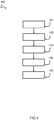
- Fig. 1 shows a schematic diagram of a method 100 for monitoring insulation between a DC bus and protective earth, the bus being in connection with a DC source.
- a first step 101 terminals of the source are connected to protective earth by a first electrical network during a first timespan.
- a second step 102 transient first electrical values related to the first network are measured at a plurality of time steps in the first timespan, wherein a first steady state value is calculated using a plurality of first measurement points at the plurality of first time steps.
- the terminals of the source are connected to protective earth by a second electrical network, during a second timespan.
- transient second electrical values related to the second network are measured at a plurality of second time steps in the second timespan, wherein a second steady state value is calculated using a plurality of second measurement points at the plurality of second time steps.
- a fifth step 105 an indication of insulation resistances between the terminals of the source and protective earth is determined based on the calculated steady state values of the first electrical value and the second electrical value.
- the DC source is connected to an AC electrical network
- the capacitance may be unknown and change over time.
- the capacitance may for instance depend on devices connected to the AC grid.
- the time required for reaching a steady state end value may be too long (unacceptable for safety).
- the delay depends on the time constant equal to R*C.
- the R value resistance
- the C value capactance
- Fig. 2 shows a schematic diagram of an embodiment of a DC bus and protective earth.
- the DC bus is in connection with a DC source 1. Terminals of the source 1 is connected to the protective earth 4.
- the insulation resistances are represented by R1 and R2.
- a first excitation can be applied.
- a second electrical excitation can be applied.
- the electric excitation 50 can be performed by applying two different DC voltages V1, V2 determined by configuration of first network and second network.
- Electrical values related to the first network and the second network 52 are measured for a limited period of time, wherein based on measurement points at a plurality of time steps, a steady state (stable) value is predicted, limiting the required for calculating the insulation resistances R1 and R2.
- the steady state value is predicted in a limited timespan smaller than the time needed for reaching steady state (cf. smaller than 5*RC).
- Fig. 3a and 3b show a schematic diagram of a measured transient electrical value, with amplitude A, in function of time t.
- Figure 3a shows an alternating sequence of transient second electrical values 54 related to the second network, followed by transient first electrical values 56 related to the first network.
- transient second electrical values 54 related to the second network
- transient first electrical values 56 related to the first network.
- the measured voltage may increase gradually (as a result of the RC delay) until the steady state value 58 is reached.
- the voltage rises in function of time in a charging phase towards the applied voltage (excitation). If the excitation voltage is reduced, a discharge phase is obtained with a falling voltage. The voltage discharges towards the new excitation voltage. The voltage increases at the fastest rate during the first time constant and the least in the last during charge. Similarly, the voltage decreases at the fastest rate during the first time constant and the least in the last during discharge.
- the charge and discharge curve can reached into 5 time constants, i.e. the point at which a substantially stable or steady state end value is reached.
- Fig. 3b shows an enlarged view, wherein the steady state value is calculated using three measurement points 60. These measurement points 60 are used for predicting/estimating the steady state end value 58. This may for instance be done by performing an exponential fit. Other models or algorithms can also be used. Only a limited period of time until t pred is required for determining the steady state end value 58, instead of until 5*RC. Hence the timespan in which transient electrical values related to the first and second network are measured can be significantly smaller than 5*RC. As shown in fig. 3b , the second timespan (t pred -t 0 ) is significantly smaller than (5*RC - t 0 ). This is also valid for the first timespan during which transient electrical values related to the first network are collected. In this example, the charging phase 80a continues until time step t pred , followed by a discharging phase 80b.
- Fig. 4a and 4b show a schematic diagram of a measured transient electrical value in function of time. Switching between connection of the terminals of the source to protective earth via the first electrical network and via the second electrical network, for example achieved by a first state ('on') and second state ('off') of a switch, is to be carried out fast enough for timely detecting an insulation error while guaranteeing safety. As a result, there may not be sufficient time for waiting for the steady state value.
- An asymmetric excitation may be employed.
- the protective earth may for example be first excited at 1/3 of the DC line voltage during a first timespan, and 2/3 of the line voltage during a second timespan.
- At least two measurement cycles are needed to determine and confirm an insulation fault.
- multiple measurements can be performed during two power line periods with the excitation to 1/3, and two power line periods with the excitation at 2/3.
- Each set of measurements can form a RC curve, from which an end value can be calculated. Hence, the end value can be calculated without waiting for it to settle.
- Two power line periods may be sufficient for performing the measurements.
- the measurement time can be significantly improved in this way. For example, a 300ms reaction time can be achieved.
- the excitation voltages are exemplary chosen as 1/3 of the DC grid voltage and 2/3 of the DC grid voltage. Due to capacitive loading between DC bus and PE, Vx1 indicated by line 61 in fig. 4A , is not reached within 40ms of excitation time, Vx2, indicated by line 62 in fig. 4B , is not reached during its 60ms of excitation time. However these end values can be derived by extrapolating the exponential RC curves. The end values are used for the calculation of the insulation resistance. In fig. 4b , the value to which the voltage would converge if a sufficiently long time is waited, i.e. the steady state value 62, is never reached.
- the invention is not limited in this context.
- a first block voltage of 1/3 of the DC source voltage may be applied for a first time duration, and a second block voltage of 2/3 of the DC source voltage may be applied for a second time duration.
- the potential difference of the protective earth becomes 1/3 of the potential difference between the positive and the negative terminal of the DC source.
- the applied voltage ratios 1/3 and 2/3 can simplify calculation of insulation resistances R1, R2. It will be appreciated that other asymmetrical ratios may also be used, for instance (1/4 and 3/4), (2/5, and 3/5), (1/5 and 4/5), etc. Many ratio pair combinations can be implemented.
- the first timespan and the second timespan can be seen as a duration in which the protective earth is linked to the first (resistor) network and the second (resistor) network, respectively.
- the protective earth may be linked to one network for 60 ms, and linked to the other network for 40 ms. It can be desired to measure over several periods of time, before an alarming insulation resistance is reported. In the example in figs. 4a and 4b , a complete measurement for providing an indication of insulation resistances between the terminals of the source and the protective earth can be conducted within 100 ms.
- Fig. 5 shows a schematic diagram of a measured transient electrical value in function of time.
- the protective earth can be capacitively coupled to the AC and DC lines so the voltage on the protective earth will follow grid frequency or higher harmonics thereof. Measuring during any whole number of power line period ⁇ t, can average out the effects of the coupled grid frequency.
- an oscillating signal 70 can be superposed on an exponential 72 (only a portion is drawn).
- the amplitudes of the oscillating signal (e.g. oscillating at 50 Hz) may be limited. However, the oscillating signal may be detrimental for the estimation of the first and second steady state value (for example using curve fitting).
- a relatively small oscillation can already have a significant influence on the calculated values of the insulation errors. For instance, an oscillating signal causing oscillations of ⁇ 0.1Volt on a signal of approximately 600 Volt may already cause significant deviations between the calculated/estimated values and the actual steady state value.
- the difference between V1 and V2 may become smaller.
- the difference V2-V1 may no longer be 1/3 of the DC source voltage, but smaller.
- the time distance between two measurement points ⁇ T can be chosen based on the powerline period of the AC grid to which the DC source is coupled. Errors caused by bad sampling can be prevented.
- the distance between two time points is an integer number of times the power line period. For instance, the distance between the two time points may be one power line period for reducing the required processing time.
- At least three successive measurement points may be determined for performing an estimation or predication of end values.
- three measurement points may be used. More than three measurement points can also be used, for instance when employing a Lenberg-Marquart algorithm.
- three measurement points are used, sampled at three time steps, namely T1, T2 and T3. When the fitted curve passed through the three points T1, T2, T3 a correct trend can be obtained for determining the steady state values.
- the time interval may be adjustable depending on the relevant powerline cycle.
- the powerline cycle is determined, for instance during initialization.
- a device may be configured arranged to determine or receive an indication of the powerline cycle. It is also envisaged that the powerline cycle is pre-configured and/or user selectable (e.g. Europe: 50Hz, United States: 60Hz).
- a exponential curve fit may be performed for calculating the steady state electrical voltage value 62.
- Fig. 6 shows a schematic diagram of an embodiment of an insulation monitoring device according to the invention.
- a DC power source 1 is present, connectable to one or more loads (not shown in figure) via a DC bus comprising conductors 12 and 13.
- the insulation of the DC bus connected to the source 1 is schematically represented as a pair of resistors R1 and R2, between the terminals of the DC source 1 and protective earth 4.
- the insulation between the DC bus and protective earth 4 is influenced by the insulation of the conductors 12 and 13, and all conductors leading to loads, as well as to the insulation of DC systems comprised in these loads.
- the resistance values of R1 and R2 are to be determined accurately and sufficiently fast for safety purposes.
- the insulation monitoring device 5 can be electrically connected to the source 1.
- the switching device 6 may include a switching device 6 and a microcontroller 7, as well as an electrical circuit 8 comprising a network of resistances, capacities and/or inductors.
- the switching device 6 can for example be a bipolar transistor or a MOSFET, controllable by the microcontroller 7, which commands the 'on' or 'off' state of the switch 6 through connection 9.
- the state of the switch 6 defines the actual circuit connected to the source at any point in time. This means that by controlling the switch 6, two different electrical networks can be created.
- Means are provided in the microcontroller 7 to measure a value, preferably a voltage at a particular point in the circuit. This measurement value is acquired through connection 10.
- the circuit is devised in such a way that two sufficiently distinct values are measured at the same point during each state (on or off) of the switch 6. If necessary, more than two values may be measured, for example one additional measurement value which is independent of the state of the switch 6, or two additional values that are dependent on the state of the switch 6, or both.
- the to be determined resistance values of R1 and R2 are calculated on the basis of these at least two measurement values, combined with the network laws applied to the two different networks corresponding respectively to the switch being on or off.
- the calculation of R1 and R2, according to the appropriate formulas, can be performed by the microcontroller 7.
- the microcontroller can be configured to check whether the values of R1 and R2 are sufficiently high. If not, an insulation failure can be detected and the terminals of the source 1 can be disconnected from any load connected to these terminals.
- a pre-alarm warning signal may be activated when R1 and R2 are near the predefined alarm level, but not yet underneath said alarm level.
- Any calculation of R1 and R2 takes two consecutive measurements, each during one condition (on or off) of the switch 6.
- a continuous monitoring can be performed by changing the condition of the switch in a sequential manner and with a given frequency.
- a main switch may be arranged for connecting or disconnecting the source 1 to the load, for example using two synchronized switches, one placed in each of the conductors of the DC bus and operated by a relay.
- the device can also operate an extra relay that prevents excessive inrush currents on DC bus capacitors. It can also discharge residual voltage on DC bus capacitors after switching off the main switch by operating an extra relay.
- the shown device can be arranged to connect terminals of the source 1 to protective earth 4 by a first electrical network during a first timespan; and subsequently measure transient first electrical value related to the first network at a plurality of time steps in the first timespan, wherein a first steady state value is calculated using a plurality of first measurement points at the plurality of first time steps.
- the device may be configured to connect the terminals of the source to protective earth 4 by a second electrical network, during a second timespan, and subsequently measure transient second electrical values related to the second network at a plurality of second time steps in the second timespan, wherein a second steady state value is calculated using a plurality of second measurement points at the plurality of second time steps. These steps may be repeated one or more times, wherein based on the calculated steady state values of the first electrical value and the second electrical value, an indication of insulation resistances between the terminals of the source and protective earth 4 can be determined.
- Fig. 7 shows a schematic diagram of an insulation monitoring device according to the invention.
- Two insulation resistances (Rf1, Rf2) representing the insulation between the DC bus terminals (positive +, negative -) of the DC source 1 and protective earth 4 have to be monitored.
- the switch S1 can be a MOSFET transistor. Other implementations are also possible for switching between the two electrical networks.
- an electrical network including: a resistor R3 between the positive source terminal and protective earth 4; two resistors R4 and R8 in series, between the negative source terminal and protective earth 4; a resistor R7 in series with S1 so that R7 and S1 are placed in parallel with the resistors R4 and R8; two resistors R5 and R6 in series, and as such connected to the terminals of the source 1.
- the resistor divider network comprises only the resistors R3, R4 and R8. Activation of S1 brings the parallel branch containing R7 into play.
- the microcontroller measures the voltages with respect to protective earth 4 at the position 16, which is the point between series resistors R4 and R8. This configuration as a resistor divider network allowing reduction of the measured voltage to a sufficiently low value, measurable by the microcontroller's circuits. Two consecutive voltage measurements can give two values, which are used to calculate R1 and R2, as explained after this.
- a capacitive coupling between DC+ or DC- and the protective earth 4 can be created through the parasitic capacitance of for example the isolation transformer and/or electromagnetic interference decoupling capacitors in the devices connected to the DC bus.
- Devices known from the prior art typically employ a high impedance resistor and must perform two measurements. Combining this with capacitive effects results in either faulty measurements or a long settling time, hence a slow device. It is generally accepted that isolation monitors should react within 40 to 300ms after an insulation fault occurs (depending on the fault magnitude) in order to protect humans.
- the time constant of the parasitic capacitance and the high impedance measurement resistor is in the order of 10ms. Further, the settling time is around 50ms. However, as these parameters may vary considerably, practice has shown that 100ms settling time per measurement is a good compromise in most cases.
- Two measurements are needed for one isolation resistance calculation, at least two or three isolation resistances should be calculated before reacting in order to create immunity against electromagnetic interference or other disturbances. It is clear that due to parasitic capacitances present in grids, the proposed isolation monitoring devices cannot react fast enough.
- grid signals may crosstalk into the protective earth. It can be likely that the protective earth carries traces of the mains voltage in the form of a voltage ripple at the mains frequency and/or one or more harmonics thereof. Filtering out these signals may slow down the acquisition of signals applied to the protective earth.
- the method according to the current invention can overcome these technical problems and can be implemented in various different types of isolation monitoring devices.
- the protective earth is excited with two voltage levels , one after the other.
- a first measurement of the protective earth voltage is taken immediately at the start of the procedure, i.e. after opening the switch.
- a second and third measurement are taken after waiting one grid period each time. These measurements are: Vpe1.1 + Vg1.1, Vpe1.2 + Vg1.2, Vpe1.3 + Vg1.3, with Vpe1 being the voltage on the protective earth due to the RC circuit with open switch and Vg being the superimposed sinusoidal voltage due to crosstalk from the mains.
- V Vpe 1 + A 1 ⁇ e ⁇ ⁇ t / tau
- A V ⁇ Vpe 1
- Rf1 and Rf2 are the insulation resistance values which are calculated. It is also envisaged that an indication of Rf1 and Rf2 is determined (for example an equivalent electrical quantity and/or a value based on a ratio of Rf1 and Rf2.
- the microcontroller 7 can be configured to open the switch S1 during a defined time (for example 60 milliseconds), afterwards switch S1 is closed (for example 40 milliseconds). This can be continuously repeated.
- resistance values R3, R4, R7 and R8 can result in excitation of the protective earth with a block voltage of 2/3 of the DC line voltage (when S1 being open) and 1/3 of the DC line voltage (when S1 being closed).
- Vx2 can be measured at pin 15 of the microcontroller, then S1 can be closed.
- Vx1 can be measured with S1 being closed at point 15.
- the voltages Vx1 and Vx2 can be measured at point 15.
- bias resistors are introduced (+ 0.5 % of resistance value R3 and R7) such that Vx2 slightly ⁇ 2/3 Vdc and Vx1 slightly > 1/3 Vdc.
- Vx2 - Vx1 ⁇ Vdc/3 in all circumstances considering injected noise and component tolerances.
- the formulas processed by the microcontroller may be only valid in that case.
- the bias resistors result in a lower insulation resistance estimate (safe) when the resistance is high and are negligible in case of insulation faults.
- the result of the resistance division R5/R6 forms the voltage reference for the AD conversion (18) and can be ⁇ Vcc (power source) of the microcontroller.
- Vref for the AD conversion
- 12 bits of the AD convertor 4096 are referred
- the measured value of the AD convertor 2/3 or 1/3 of Vdc and this measurement is referred to Vdc.
- Vref can be determined based on the DC voltage.
- a voltage division is used for determining Vref.
- Vref can be proportional to the DC source voltage. It will be appreciated that the voltage supply network of the microcontroller is not drawn. Vref can become a separate input that can be used for measuring the DC source voltage.
- a filter (low pass filter) can be added for the measurements of Vx2 and Vx1.
- the cut-off frequency of this filter must be 10 times higher than the measuring frequency (60 and 40 milliseconds). Filtering of low frequencies is not a solution, because the measurement time increase and this is not allowed.
- the device switches at fixed intervals between the conditions S1 'on' and S1 'off', for example with a frequency of 10Hz.
- a given delay e.g. 50ms
- an alarm is triggered if an insulation error is detected in one or more cycles.
- several measurements are taken, and an alarm is triggered if an insulation error is detected in successive cycles.
- a measurement of the insulation resistance can be obtained with each cycle.
- One cycle can be sufficient, but reliability can be increased by repeating cycles and also monitor the evolution of the insulation resistance over time.
- protective earth may relate to a protective enclosure, such as a chassis of a car, as well as a real connection to earth, depending on the application.
- the device can also perform other safety functions useful for dedicated applications, e.g.: under and over voltage protection, temperature measurement, self-testing, warning level indication, etc.
- This can be done by re-programming the micro-controller, or by using a microcontroller designed to perform additional measurements, calculations and/or actuate additional command signals for relays or the like so that values other than the insulation resistances R1 and R2 are calculated, in addition to R1 and R2.
- a plurality of values that are to be checked, may be calculated by the microcontroller 7, which may then activate a number of safety measures: relays for interrupting current, alarm signals, etc.
- the method may include computer implemented steps. All above mentioned steps can be computer implemented steps.
- Embodiments may comprise computer apparatus, wherein processes performed in computer apparatus.
- the invention also extends to computer programs, particularly computer programs on or in a carrier, adapted for putting the invention into practice.
- the program may be in the form of source or object code or in any other form suitable for use in the implementation of the processes according to the invention.
- the carrier may be any entity or device capable of carrying the program.
- the carrier may comprise a storage medium, such as a ROM, for example a semiconductor ROM or hard disk.
- the carrier may be a transmissible carrier such as an electrical or optical signal which may be conveyed via electrical or optical cable or by radio or other means, e.g. via the internet or cloud.
- Some embodiments may be implemented, for example, using a machine or tangible computer-readable medium or article which may store an instruction or a set of instructions that, if executed by a machine, may cause the machine to perform a method and/or operations in accordance with the embodiments.
- Various embodiments may be implemented using hardware elements, software elements, or a combination of both.
- hardware elements may include processors, microprocessors, circuits, application specific integrated circuits (ASIC), programmable logic devices (PLD), digital signal processors (DSP), field programmable gate array (FPGA), logic gates, registers, semiconductor device, microchips, chip sets, et cetera.
- software may include software components, programs, applications, computer programs, application programs, system programs, machine programs, operating system software, mobile apps, middleware, firmware, software modules, routines, subroutines, functions, computer implemented methods, procedures, software interfaces, application program interfaces (API), methods, instruction sets, computing code, computer code, et cetera.
- API application program interfaces
- first”, “second”, and the like, as used herein can distinguish one element from another by indicating different instances of like elements. It will be understood that terms “first”, “second”, and the like do not denote any order, quantity, importance, sequence, either temporally, spatially, in ranking, or in any other manner.
- network may include either a single component or a plurality of components, which are either active and/or passive and are connected or otherwise coupled together (for example, as one or more integrated circuit chips) to provide the described function.
- any reference signs placed between parentheses shall not be construed as limiting the claim.
- the word 'comprising' does not exclude the presence of other features or steps than those listed in a claim.
- the words 'a' and 'an' shall not be construed as limited to 'only one', but instead are used to mean 'at least one', and do not exclude a plurality.
- the mere fact that certain measures are recited in mutually different claims does not indicate that a combination of these measures cannot be used to an advantage.
Priority Applications (7)
| Application Number | Priority Date | Filing Date | Title |
|---|---|---|---|
| DK18248091.3T DK3675302T3 (da) | 2018-12-27 | 2018-12-27 | En fremgangsmåde og indretning til overvågning af isolation mellem en jævnstrømsbus og beskyttelsesjording |
| EP18248091.3A EP3675302B1 (en) | 2018-12-27 | 2018-12-27 | A method and device for monitoring insulation between a dc bus and protective earth |
| PL18248091T PL3675302T3 (pl) | 2018-12-27 | 2018-12-27 | Sposób i urządzenie do monitorowania izolacji pomiędzy szyną dc a uziemieniem ochronnym |
| PCT/EP2019/086901 WO2020136157A1 (en) | 2018-12-27 | 2019-12-23 | A method and device for monitoring insulation between a dc bus and protective earth |
| US17/359,023 US11747378B2 (en) | 2018-12-27 | 2019-12-23 | Method and device for monitoring insulation between a DC bus and protective earth |
| JP2021538184A JP2022524264A (ja) | 2018-12-27 | 2019-12-23 | 直流バスと保護接地との間の絶縁を監視する方法及び装置 |
| CN201980091260.5A CN113678334A (zh) | 2018-12-27 | 2019-12-23 | 一种用于监测dc总线与保护地之间的绝缘的方法和设备 |
Applications Claiming Priority (1)
| Application Number | Priority Date | Filing Date | Title |
|---|---|---|---|
| EP18248091.3A EP3675302B1 (en) | 2018-12-27 | 2018-12-27 | A method and device for monitoring insulation between a dc bus and protective earth |
Publications (2)
| Publication Number | Publication Date |
|---|---|
| EP3675302A1 EP3675302A1 (en) | 2020-07-01 |
| EP3675302B1 true EP3675302B1 (en) | 2021-04-14 |
Family
ID=65011785
Family Applications (1)
| Application Number | Title | Priority Date | Filing Date |
|---|---|---|---|
| EP18248091.3A Active EP3675302B1 (en) | 2018-12-27 | 2018-12-27 | A method and device for monitoring insulation between a dc bus and protective earth |
Country Status (7)
| Country | Link |
|---|---|
| US (1) | US11747378B2 (ja) |
| EP (1) | EP3675302B1 (ja) |
| JP (1) | JP2022524264A (ja) |
| CN (1) | CN113678334A (ja) |
| DK (1) | DK3675302T3 (ja) |
| PL (1) | PL3675302T3 (ja) |
| WO (1) | WO2020136157A1 (ja) |
Families Citing this family (3)
| Publication number | Priority date | Publication date | Assignee | Title |
|---|---|---|---|---|
| EP4019990A1 (en) * | 2020-12-28 | 2022-06-29 | Fico Triad, S.A. | Systems and methods for determining insulation resistance |
| US11833910B2 (en) | 2021-03-12 | 2023-12-05 | Analog Devices International Unlimited Company | Dynamic isolation monitoring with low sensitivity to noise |
| DE102022107832A1 (de) * | 2022-04-01 | 2023-10-05 | Illinois Tool Works Inc. | Aktives erdungsysstem mit vorausschauender überwachung |
Family Cites Families (12)
| Publication number | Priority date | Publication date | Assignee | Title |
|---|---|---|---|---|
| GB2317278A (en) * | 1996-09-11 | 1998-03-18 | Cegelec Controls Ltd | Apparatus and method for monitoring an earth-leakage state of a power distribution system |
| ES2320318T3 (es) * | 2001-06-08 | 2009-05-21 | "VLAAMSE INSTELLING VOOR TECHNOLOGISCH ONDERZOEK", AFGEKORT "V.I.T.O." | Dispositivo de seguridad para monitorizar el aislamiento de un bus dc. |
| JP2006343267A (ja) * | 2005-06-10 | 2006-12-21 | Chugoku Electric Power Co Inc:The | 直流回路の絶縁抵抗測定器、静電容量測定器、絶縁抵抗測定方法および静電容量測定方法 |
| JP5818820B2 (ja) * | 2011-01-21 | 2015-11-18 | 三菱電機株式会社 | 絶縁抵抗検知回路 |
| US9069019B2 (en) * | 2011-06-20 | 2015-06-30 | Chargepoint, Inc. | Apparatus and method for measuring ground impedance of a circuit |
| DE102012218107B4 (de) * | 2012-10-04 | 2023-04-27 | Bender Gmbh & Co. Kg | Verfahren zur Überwachung und Messung eines Isolationswiderstands mit einem störresistenten Messsignal und zugehöriger Signalgenerator |
| JP2014081267A (ja) * | 2012-10-16 | 2014-05-08 | Sanyo Electric Co Ltd | 電源装置 |
| DE102013209142A1 (de) * | 2013-05-16 | 2014-11-20 | Bayerische Motoren Werke Aktiengesellschaft | Verfahren zur Ermittlung eines Isolationswiderstands eines mehrere Teilnetze umfassenden Energieversorgungsnetzwerks eines Fahrzeugs |
| JP6229876B2 (ja) * | 2013-08-27 | 2017-11-15 | 日本電産リード株式会社 | 検査装置 |
| KR101991910B1 (ko) * | 2016-11-16 | 2019-06-21 | 주식회사 엘지화학 | 배터리의 절연 저항 산출 장치 및 방법 |
| CN108333428B (zh) * | 2017-12-30 | 2020-09-18 | 宁德时代新能源科技股份有限公司 | 绝缘电阻测量设备和方法 |
| CN110412418B (zh) * | 2019-07-22 | 2020-07-31 | 国网湖北省电力有限公司电力科学研究院 | 基于接地电流测量的绝缘管型母线绝缘诊断和定位方法 |
-
2018
- 2018-12-27 DK DK18248091.3T patent/DK3675302T3/da active
- 2018-12-27 EP EP18248091.3A patent/EP3675302B1/en active Active
- 2018-12-27 PL PL18248091T patent/PL3675302T3/pl unknown
-
2019
- 2019-12-23 US US17/359,023 patent/US11747378B2/en active Active
- 2019-12-23 CN CN201980091260.5A patent/CN113678334A/zh active Pending
- 2019-12-23 WO PCT/EP2019/086901 patent/WO2020136157A1/en active Application Filing
- 2019-12-23 JP JP2021538184A patent/JP2022524264A/ja active Pending
Non-Patent Citations (1)
| Title |
|---|
| None * |
Also Published As
| Publication number | Publication date |
|---|---|
| JP2022524264A (ja) | 2022-05-02 |
| WO2020136157A1 (en) | 2020-07-02 |
| CN113678334A (zh) | 2021-11-19 |
| PL3675302T3 (pl) | 2021-09-06 |
| US11747378B2 (en) | 2023-09-05 |
| EP3675302A1 (en) | 2020-07-01 |
| DK3675302T3 (da) | 2021-05-10 |
| US20230152358A1 (en) | 2023-05-18 |
Similar Documents
| Publication | Publication Date | Title |
|---|---|---|
| US11022655B2 (en) | Method and control system for faulted phase detection | |
| US11747378B2 (en) | Method and device for monitoring insulation between a DC bus and protective earth | |
| KR101813355B1 (ko) | 절연 검출기 및 전기 기기 | |
| US7219023B2 (en) | Method and device for the detection of fault current arcing in electric circuits | |
| US8310242B2 (en) | Circuit arrangement and method for insulation monitoring for inverter applications | |
| EP2439827B1 (en) | System for detection of a ground fault in a high resistance ground network | |
| CN107636922B (zh) | 直流电保护系统的改进或及其相关改进 | |
| US20150346266A1 (en) | System and method for pulsed ground fault detection and localization | |
| US20060125486A1 (en) | System and method of locating ground fault in electrical power distribution system | |
| US8283929B2 (en) | Method and apparatus to monitor electric isolation of a high-voltage direct current electrical circuit | |
| EP3224954B1 (en) | A method for estimating an electrical operating time of a circuit breaker | |
| US10191102B2 (en) | Automatic current transformer polarity correction | |
| US20160245855A1 (en) | Systems and methods for insulation impedance monitoring | |
| US11009557B2 (en) | Method and device for short-circuit monitoring of a three-phase load | |
| JP2013156247A (ja) | 電気的じょう乱の位置の特定 | |
| US10338122B2 (en) | Method and device for detecting a fault in an electrical network | |
| US10228406B2 (en) | Detecting a fault, in particular a transient fault, in an electrical network | |
| US10871513B2 (en) | Differential protection method in an electrical power supply system and protective apparatus for carrying out a differential protection method | |
| EP3015875B1 (en) | Insulation monitoring device | |
| TWI751280B (zh) | 不存在電壓檢測器 | |
| CN112335163A (zh) | 无源的滤波器电路的电容器功能的确定 |
Legal Events
| Date | Code | Title | Description |
|---|---|---|---|
| PUAI | Public reference made under article 153(3) epc to a published international application that has entered the european phase |
Free format text: ORIGINAL CODE: 0009012 |
|
| STAA | Information on the status of an ep patent application or granted ep patent |
Free format text: STATUS: REQUEST FOR EXAMINATION WAS MADE |
|
| 17P | Request for examination filed |
Effective date: 20191223 |
|
| AK | Designated contracting states |
Kind code of ref document: A1 Designated state(s): AL AT BE BG CH CY CZ DE DK EE ES FI FR GB GR HR HU IE IS IT LI LT LU LV MC MK MT NL NO PL PT RO RS SE SI SK SM TR |
|
| AX | Request for extension of the european patent |
Extension state: BA ME |
|
| GRAP | Despatch of communication of intention to grant a patent |
Free format text: ORIGINAL CODE: EPIDOSNIGR1 |
|
| STAA | Information on the status of an ep patent application or granted ep patent |
Free format text: STATUS: GRANT OF PATENT IS INTENDED |
|
| INTG | Intention to grant announced |
Effective date: 20201026 |
|
| GRAS | Grant fee paid |
Free format text: ORIGINAL CODE: EPIDOSNIGR3 |
|
| GRAA | (expected) grant |
Free format text: ORIGINAL CODE: 0009210 |
|
| STAA | Information on the status of an ep patent application or granted ep patent |
Free format text: STATUS: THE PATENT HAS BEEN GRANTED |
|
| AK | Designated contracting states |
Kind code of ref document: B1 Designated state(s): AL AT BE BG CH CY CZ DE DK EE ES FI FR GB GR HR HU IE IS IT LI LT LU LV MC MK MT NL NO PL PT RO RS SE SI SK SM TR |
|
| REG | Reference to a national code |
Ref country code: GB Ref legal event code: FG4D |
|
| REG | Reference to a national code |
Ref country code: CH Ref legal event code: EP |
|
| REG | Reference to a national code |
Ref country code: CH Ref legal event code: NV Representative=s name: VALIPAT S.A. C/O BOVARD SA NEUCHATEL, CH |
|
| REG | Reference to a national code |
Ref country code: DE Ref legal event code: R096 Ref document number: 602018015489 Country of ref document: DE |
|
| REG | Reference to a national code |
Ref country code: DK Ref legal event code: T3 Effective date: 20210507 |
|
| REG | Reference to a national code |
Ref country code: IE Ref legal event code: FG4D |
|
| REG | Reference to a national code |
Ref country code: AT Ref legal event code: REF Ref document number: 1383314 Country of ref document: AT Kind code of ref document: T Effective date: 20210515 |
|
| REG | Reference to a national code |
Ref country code: FI Ref legal event code: FGE |
|
| REG | Reference to a national code |
Ref country code: NL Ref legal event code: FP |
|
| REG | Reference to a national code |
Ref country code: SE Ref legal event code: TRGR |
|
| REG | Reference to a national code |
Ref country code: NO Ref legal event code: T2 Effective date: 20210414 |
|
| REG | Reference to a national code |
Ref country code: LT Ref legal event code: MG9D |
|
| REG | Reference to a national code |
Ref country code: AT Ref legal event code: MK05 Ref document number: 1383314 Country of ref document: AT Kind code of ref document: T Effective date: 20210414 |
|
| PG25 | Lapsed in a contracting state [announced via postgrant information from national office to epo] |
Ref country code: LT Free format text: LAPSE BECAUSE OF FAILURE TO SUBMIT A TRANSLATION OF THE DESCRIPTION OR TO PAY THE FEE WITHIN THE PRESCRIBED TIME-LIMIT Effective date: 20210414 Ref country code: HR Free format text: LAPSE BECAUSE OF FAILURE TO SUBMIT A TRANSLATION OF THE DESCRIPTION OR TO PAY THE FEE WITHIN THE PRESCRIBED TIME-LIMIT Effective date: 20210414 Ref country code: BG Free format text: LAPSE BECAUSE OF FAILURE TO SUBMIT A TRANSLATION OF THE DESCRIPTION OR TO PAY THE FEE WITHIN THE PRESCRIBED TIME-LIMIT Effective date: 20210714 Ref country code: AT Free format text: LAPSE BECAUSE OF FAILURE TO SUBMIT A TRANSLATION OF THE DESCRIPTION OR TO PAY THE FEE WITHIN THE PRESCRIBED TIME-LIMIT Effective date: 20210414 |
|
| PG25 | Lapsed in a contracting state [announced via postgrant information from national office to epo] |
Ref country code: RS Free format text: LAPSE BECAUSE OF FAILURE TO SUBMIT A TRANSLATION OF THE DESCRIPTION OR TO PAY THE FEE WITHIN THE PRESCRIBED TIME-LIMIT Effective date: 20210414 Ref country code: LV Free format text: LAPSE BECAUSE OF FAILURE TO SUBMIT A TRANSLATION OF THE DESCRIPTION OR TO PAY THE FEE WITHIN THE PRESCRIBED TIME-LIMIT Effective date: 20210414 Ref country code: PT Free format text: LAPSE BECAUSE OF FAILURE TO SUBMIT A TRANSLATION OF THE DESCRIPTION OR TO PAY THE FEE WITHIN THE PRESCRIBED TIME-LIMIT Effective date: 20210816 Ref country code: GR Free format text: LAPSE BECAUSE OF FAILURE TO SUBMIT A TRANSLATION OF THE DESCRIPTION OR TO PAY THE FEE WITHIN THE PRESCRIBED TIME-LIMIT Effective date: 20210715 Ref country code: IS Free format text: LAPSE BECAUSE OF FAILURE TO SUBMIT A TRANSLATION OF THE DESCRIPTION OR TO PAY THE FEE WITHIN THE PRESCRIBED TIME-LIMIT Effective date: 20210814 |
|
| REG | Reference to a national code |
Ref country code: DE Ref legal event code: R097 Ref document number: 602018015489 Country of ref document: DE |
|
| PG25 | Lapsed in a contracting state [announced via postgrant information from national office to epo] |
Ref country code: SK Free format text: LAPSE BECAUSE OF FAILURE TO SUBMIT A TRANSLATION OF THE DESCRIPTION OR TO PAY THE FEE WITHIN THE PRESCRIBED TIME-LIMIT Effective date: 20210414 Ref country code: SM Free format text: LAPSE BECAUSE OF FAILURE TO SUBMIT A TRANSLATION OF THE DESCRIPTION OR TO PAY THE FEE WITHIN THE PRESCRIBED TIME-LIMIT Effective date: 20210414 Ref country code: ES Free format text: LAPSE BECAUSE OF FAILURE TO SUBMIT A TRANSLATION OF THE DESCRIPTION OR TO PAY THE FEE WITHIN THE PRESCRIBED TIME-LIMIT Effective date: 20210414 Ref country code: EE Free format text: LAPSE BECAUSE OF FAILURE TO SUBMIT A TRANSLATION OF THE DESCRIPTION OR TO PAY THE FEE WITHIN THE PRESCRIBED TIME-LIMIT Effective date: 20210414 Ref country code: CZ Free format text: LAPSE BECAUSE OF FAILURE TO SUBMIT A TRANSLATION OF THE DESCRIPTION OR TO PAY THE FEE WITHIN THE PRESCRIBED TIME-LIMIT Effective date: 20210414 Ref country code: RO Free format text: LAPSE BECAUSE OF FAILURE TO SUBMIT A TRANSLATION OF THE DESCRIPTION OR TO PAY THE FEE WITHIN THE PRESCRIBED TIME-LIMIT Effective date: 20210414 |
|
| PLBE | No opposition filed within time limit |
Free format text: ORIGINAL CODE: 0009261 |
|
| STAA | Information on the status of an ep patent application or granted ep patent |
Free format text: STATUS: NO OPPOSITION FILED WITHIN TIME LIMIT |
|
| 26N | No opposition filed |
Effective date: 20220117 |
|
| PG25 | Lapsed in a contracting state [announced via postgrant information from national office to epo] |
Ref country code: IS Free format text: LAPSE BECAUSE OF FAILURE TO SUBMIT A TRANSLATION OF THE DESCRIPTION OR TO PAY THE FEE WITHIN THE PRESCRIBED TIME-LIMIT Effective date: 20210814 Ref country code: AL Free format text: LAPSE BECAUSE OF FAILURE TO SUBMIT A TRANSLATION OF THE DESCRIPTION OR TO PAY THE FEE WITHIN THE PRESCRIBED TIME-LIMIT Effective date: 20210414 |
|
| PG25 | Lapsed in a contracting state [announced via postgrant information from national office to epo] |
Ref country code: MC Free format text: LAPSE BECAUSE OF FAILURE TO SUBMIT A TRANSLATION OF THE DESCRIPTION OR TO PAY THE FEE WITHIN THE PRESCRIBED TIME-LIMIT Effective date: 20210414 Ref country code: IT Free format text: LAPSE BECAUSE OF FAILURE TO SUBMIT A TRANSLATION OF THE DESCRIPTION OR TO PAY THE FEE WITHIN THE PRESCRIBED TIME-LIMIT Effective date: 20210414 |
|
| PG25 | Lapsed in a contracting state [announced via postgrant information from national office to epo] |
Ref country code: LU Free format text: LAPSE BECAUSE OF NON-PAYMENT OF DUE FEES Effective date: 20211227 Ref country code: IE Free format text: LAPSE BECAUSE OF NON-PAYMENT OF DUE FEES Effective date: 20211227 |
|
| PGFP | Annual fee paid to national office [announced via postgrant information from national office to epo] |
Ref country code: CH Payment date: 20230101 Year of fee payment: 5 |
|
| PG25 | Lapsed in a contracting state [announced via postgrant information from national office to epo] |
Ref country code: CY Free format text: LAPSE BECAUSE OF FAILURE TO SUBMIT A TRANSLATION OF THE DESCRIPTION OR TO PAY THE FEE WITHIN THE PRESCRIBED TIME-LIMIT Effective date: 20210414 |
|
| P01 | Opt-out of the competence of the unified patent court (upc) registered |
Effective date: 20230528 |
|
| PG25 | Lapsed in a contracting state [announced via postgrant information from national office to epo] |
Ref country code: HU Free format text: LAPSE BECAUSE OF FAILURE TO SUBMIT A TRANSLATION OF THE DESCRIPTION OR TO PAY THE FEE WITHIN THE PRESCRIBED TIME-LIMIT; INVALID AB INITIO Effective date: 20181227 |
|
| PGFP | Annual fee paid to national office [announced via postgrant information from national office to epo] |
Ref country code: NL Payment date: 20231121 Year of fee payment: 6 |
|
| PGFP | Annual fee paid to national office [announced via postgrant information from national office to epo] |
Ref country code: GB Payment date: 20231124 Year of fee payment: 6 |
|
| PGFP | Annual fee paid to national office [announced via postgrant information from national office to epo] |
Ref country code: SE Payment date: 20231121 Year of fee payment: 6 Ref country code: NO Payment date: 20231123 Year of fee payment: 6 Ref country code: FR Payment date: 20231122 Year of fee payment: 6 Ref country code: FI Payment date: 20231121 Year of fee payment: 6 Ref country code: DK Payment date: 20231121 Year of fee payment: 6 Ref country code: DE Payment date: 20231121 Year of fee payment: 6 |
|
| PGFP | Annual fee paid to national office [announced via postgrant information from national office to epo] |
Ref country code: PL Payment date: 20231127 Year of fee payment: 6 Ref country code: BE Payment date: 20231121 Year of fee payment: 6 |
|
| PG25 | Lapsed in a contracting state [announced via postgrant information from national office to epo] |
Ref country code: MK Free format text: LAPSE BECAUSE OF FAILURE TO SUBMIT A TRANSLATION OF THE DESCRIPTION OR TO PAY THE FEE WITHIN THE PRESCRIBED TIME-LIMIT Effective date: 20210414 |
|
| PGFP | Annual fee paid to national office [announced via postgrant information from national office to epo] |
Ref country code: CH Payment date: 20240101 Year of fee payment: 6 |