EP3675284A1 - Heater - Google Patents
Heater Download PDFInfo
- Publication number
- EP3675284A1 EP3675284A1 EP19191623.8A EP19191623A EP3675284A1 EP 3675284 A1 EP3675284 A1 EP 3675284A1 EP 19191623 A EP19191623 A EP 19191623A EP 3675284 A1 EP3675284 A1 EP 3675284A1
- Authority
- EP
- European Patent Office
- Prior art keywords
- crimping
- filament
- fixing member
- crimping portion
- light
- Prior art date
- Legal status (The legal status is an assumption and is not a legal conclusion. Google has not performed a legal analysis and makes no representation as to the accuracy of the status listed.)
- Withdrawn
Links
Images


Classifications
-
- H—ELECTRICITY
- H05—ELECTRIC TECHNIQUES NOT OTHERWISE PROVIDED FOR
- H05B—ELECTRIC HEATING; ELECTRIC LIGHT SOURCES NOT OTHERWISE PROVIDED FOR; CIRCUIT ARRANGEMENTS FOR ELECTRIC LIGHT SOURCES, IN GENERAL
- H05B3/00—Ohmic-resistance heating
- H05B3/0033—Heating devices using lamps
-
- H—ELECTRICITY
- H05—ELECTRIC TECHNIQUES NOT OTHERWISE PROVIDED FOR
- H05B—ELECTRIC HEATING; ELECTRIC LIGHT SOURCES NOT OTHERWISE PROVIDED FOR; CIRCUIT ARRANGEMENTS FOR ELECTRIC LIGHT SOURCES, IN GENERAL
- H05B3/00—Ohmic-resistance heating
- H05B3/10—Heating elements characterised by the composition or nature of the materials or by the arrangement of the conductor
- H05B3/12—Heating elements characterised by the composition or nature of the materials or by the arrangement of the conductor characterised by the composition or nature of the conductive material
- H05B3/14—Heating elements characterised by the composition or nature of the materials or by the arrangement of the conductor characterised by the composition or nature of the conductive material the material being non-metallic
- H05B3/145—Carbon only, e.g. carbon black, graphite
-
- G—PHYSICS
- G03—PHOTOGRAPHY; CINEMATOGRAPHY; ANALOGOUS TECHNIQUES USING WAVES OTHER THAN OPTICAL WAVES; ELECTROGRAPHY; HOLOGRAPHY
- G03G—ELECTROGRAPHY; ELECTROPHOTOGRAPHY; MAGNETOGRAPHY
- G03G15/00—Apparatus for electrographic processes using a charge pattern
- G03G15/20—Apparatus for electrographic processes using a charge pattern for fixing, e.g. by using heat
- G03G15/2003—Apparatus for electrographic processes using a charge pattern for fixing, e.g. by using heat using heat
-
- H—ELECTRICITY
- H01—ELECTRIC ELEMENTS
- H01K—ELECTRIC INCANDESCENT LAMPS
- H01K1/00—Details
- H01K1/02—Incandescent bodies
- H01K1/04—Incandescent bodies characterised by the material thereof
- H01K1/06—Carbon bodies
-
- H—ELECTRICITY
- H01—ELECTRIC ELEMENTS
- H01K—ELECTRIC INCANDESCENT LAMPS
- H01K1/00—Details
- H01K1/02—Incandescent bodies
- H01K1/16—Electric connection thereto
-
- H—ELECTRICITY
- H01—ELECTRIC ELEMENTS
- H01K—ELECTRIC INCANDESCENT LAMPS
- H01K1/00—Details
- H01K1/18—Mountings or supports for the incandescent body
- H01K1/24—Mounts for lamps with connections at opposite ends, e.g. for tubular lamp
-
- H—ELECTRICITY
- H01—ELECTRIC ELEMENTS
- H01K—ELECTRIC INCANDESCENT LAMPS
- H01K3/00—Apparatus or processes adapted to the manufacture, installing, removal, or maintenance of incandescent lamps or parts thereof
- H01K3/06—Attaching of incandescent bodies to mount
-
- H—ELECTRICITY
- H01—ELECTRIC ELEMENTS
- H01K—ELECTRIC INCANDESCENT LAMPS
- H01K7/00—Lamps for purposes other than general lighting
-
- H—ELECTRICITY
- H05—ELECTRIC TECHNIQUES NOT OTHERWISE PROVIDED FOR
- H05B—ELECTRIC HEATING; ELECTRIC LIGHT SOURCES NOT OTHERWISE PROVIDED FOR; CIRCUIT ARRANGEMENTS FOR ELECTRIC LIGHT SOURCES, IN GENERAL
- H05B3/00—Ohmic-resistance heating
- H05B3/0033—Heating devices using lamps
- H05B3/009—Heating devices using lamps heating devices not specially adapted for a particular application
-
- H—ELECTRICITY
- H05—ELECTRIC TECHNIQUES NOT OTHERWISE PROVIDED FOR
- H05B—ELECTRIC HEATING; ELECTRIC LIGHT SOURCES NOT OTHERWISE PROVIDED FOR; CIRCUIT ARRANGEMENTS FOR ELECTRIC LIGHT SOURCES, IN GENERAL
- H05B3/00—Ohmic-resistance heating
- H05B3/02—Details
- H05B3/04—Waterproof or air-tight seals for heaters
-
- H—ELECTRICITY
- H05—ELECTRIC TECHNIQUES NOT OTHERWISE PROVIDED FOR
- H05B—ELECTRIC HEATING; ELECTRIC LIGHT SOURCES NOT OTHERWISE PROVIDED FOR; CIRCUIT ARRANGEMENTS FOR ELECTRIC LIGHT SOURCES, IN GENERAL
- H05B3/00—Ohmic-resistance heating
- H05B3/40—Heating elements having the shape of rods or tubes
-
- H—ELECTRICITY
- H01—ELECTRIC ELEMENTS
- H01R—ELECTRICALLY-CONDUCTIVE CONNECTIONS; STRUCTURAL ASSOCIATIONS OF A PLURALITY OF MUTUALLY-INSULATED ELECTRICAL CONNECTING ELEMENTS; COUPLING DEVICES; CURRENT COLLECTORS
- H01R4/00—Electrically-conductive connections between two or more conductive members in direct contact, i.e. touching one another; Means for effecting or maintaining such contact; Electrically-conductive connections having two or more spaced connecting locations for conductors and using contact members penetrating insulation
- H01R4/10—Electrically-conductive connections between two or more conductive members in direct contact, i.e. touching one another; Means for effecting or maintaining such contact; Electrically-conductive connections having two or more spaced connecting locations for conductors and using contact members penetrating insulation effected solely by twisting, wrapping, bending, crimping, or other permanent deformation
- H01R4/18—Electrically-conductive connections between two or more conductive members in direct contact, i.e. touching one another; Means for effecting or maintaining such contact; Electrically-conductive connections having two or more spaced connecting locations for conductors and using contact members penetrating insulation effected solely by twisting, wrapping, bending, crimping, or other permanent deformation by crimping
Definitions
- Embodiments described herein relate generally to a heater.
- a heater as a heat source
- one containing carbon is known as a filament that radiates infrared light by electric power supplied from the outside.
- the filament radiates heat by the electric power supplied through a conductive support member supporting both ends and a lead wire connected to the support member so that light is generated from the filament.
- an object of the embodiments is to provide a heater capable of improving durability.
- a heater 1 includes a light-emitting tube 2, a filament 30, a lead wire 40, and a fixing member 50. Infrared light is transmitted through the light-emitting tube 2.
- the filament 30 contains carbon, is disposed inside the light-emitting tube 2, and extends in the tube axis direction of the light-emitting tube 2.
- the lead wire 40 supplies electric power to the filament 30.
- the fixing member 50 includes a first crimping portion 51 and a second crimping portion 52 and fixes the filament 30 and the lead wire 40 so as to be electrically connected to each other.
- the first crimping portion 51 crimps the filament 30.
- the second crimping portion 52 crimps the lead wire 40.
- each of the first crimping portion 51 and the second crimping portion 52 is disposed so as to be individually crimped.
- the dimension of the fixing member 50 according to the embodiment in the longitudinal direction to be described below is set such that the first crimping portion 51 is larger than the second crimping portion 52.
- the second crimping portion 52 includes a pair of crimping pieces 521 and 522 which extends from a main body portion 54 of the fixing member 50 on which the lead wire 40 is placed in the width direction intersecting the longitudinal direction of the fixing member 50 and is respectively caulked so as to overlap the main body portion 54 with the lead wire 40 interposed therebetween.
- the fixing member 50 includes a connection portion 53 which is disposed between the first crimping portion 51 and the second crimping portion 52.
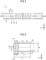
- FIG. 1 is a side view of a heater according to the embodiment.
- the heater 1 illustrated in FIG. 1 is used to heat a heating object such as an irradiation object or an irradiation space and is used as, for example, a drying device for drying ink or the like printed on a printed medium in a printed medium drying process or a drying device for heating and drying paint coated on a material in a painting process.
- FIG. 1 illustrates a three-dimensional orthogonal coordinate system including a Z-axis set such that a direction in which a heating object (not illustrated) is disposed on the heater 1 is a negative direction. Such an orthogonal coordinate system is also illustrated in other drawings used in the description below.
- the heater 1 includes a light-emitting tube 2, a filament 30, an inner lead 40, a fixing member 50, a metal foil 60, and an outer lead 70.
- the light-emitting tube 2 is an elongated member that includes a cylindrical portion 10 and a seal portion 20 and is set such that the entire length is long in the tube axis direction corresponding to the Y-axis direction as compared with the tube diameter.
- the cylindrical portion 10 is formed of, for example, quartz glass.
- the cylindrical portion 10 is transparent and transmits inner light to the outside.
- the light-emitting tube 2 may be a colored bulb in which quartz glass is colored or may be one containing a metal mixture or the like in quartz glass.
- the light-emitting tube 2 may be obtained such that an outer wall of a glass tube is coated with, for example, a coating film formed of a material having high reflection efficiency or a material absorbing light irradiated from the heater and emitting infrared light.
- the cylindrical portion 10 has an inner space and a gas is filled in such a space.
- the gas is, for example, an argon gas at about 0.8 atm.
- the gas may have a low thermal conductivity and may contain, for example, a gas of one or a combination of krypton, xenon, argon, neon, and the like.
- the seal portion 20 is formed by heating and deforming the same quartz glass as the cylindrical portion 10 using heating means such as a gas burner (not illustrated).
- the seal portion 20 is provided at both end portions of the cylindrical portion 10 in the longitudinal direction (the Y-axis direction).
- the seal portion 20 is a sealing portion and seals the cylindrical portion 10.
- the seal portion 20 of the embodiment is formed in a plate shape by pinch seal. Additionally, the seal portion 20 may be formed in a columnar shape by shrink seal.
- the filament 30 is disposed inside the light-emitting tube 2.
- the filament 30 is, for example, a carbon filament which is formed of a material containing carbon such as carbon fiber.
- the filament 30 is a string-shaped member or an elongated plate-shaped member extending in the longitudinal direction of the cylindrical portion 10.
- the filament 30 illustrated in FIG. 1 is wound so that the axial direction follows the longitudinal direction of the cylindrical portion 10 and has desired light-emitting characteristics.
- the filament 30 may be a mesh-shaped, tubular, or plate-shaped member extending in the longitudinal direction of the cylindrical portion 10.
- the inner lead 40 is a member that supplies electric power to the filament 30. One end of the inner lead 40 is electrically connected to the fixing member 50 and the other end thereof is electrically connected to the metal foil 60.
- the inner lead 40 is, for example, a molybdenum rod.
- the inner lead 40 is an example of the inner lead.
- the fixing member 50 is a member that fixes the filament 30 and the inner lead 40 so as to be electrically connected to each other. Further, a pair of the fixing members 50 respectively connected to both ends of the filament 30 holds the filament 30 by applying an appropriate tension to the filament 30. The pair of fixing members 50 fixes the filament 30 into the cylindrical portion 10 by respectively pulling both ends of the filament 30 toward both end portions of the cylindrical portion 10 in the longitudinal direction.
- the fixing member 50 is formed of a conductive metal material containing nickel or copper.
- the fixing member 50 may be an alloy.
- a detailed description of the fixing member 50 connecting the filament 30 and the inner lead 40 to each other will be made below with reference to FIGS. 2 to 4B .
- One end of the metal foil 60 is connected to the inner lead 40 and the other end thereof is connected to the outer lead 70.
- Each metal foil 60 is disposed inside the seal portion 20.
- the metal foil 60 is, for example, a molybdenum foil.
- the metal foil 60 is disposed along a plate-shaped surface of the seal portion 20.
- the outer lead 70 connects the metal foil 60 and an external power supply (not illustrated) to each other. One end of the outer lead 70 is connected to the metal foil 60 and the other end is exposed to the outside of the light-emitting tube 2. The other end of the outer lead 70 is electrically connected to a cable (not illustrated) through a connector (not illustrated) along with the seal portion 20.
- the outer lead 70 is, for example, a molybdenum rod.
- the heater 1 with such a configuration, electric power supplied from the external power supply (not illustrated) through the connector connected to the external power supply (not illustrated), the cable, the outer lead 70, the metal foil 60, the inner lead 40, and the fixing member 50 is fed to the filament 30 so that the filament 30 generates infrared light.
- FIG. 2 is an enlarged view of the fixing member of the heater according to the embodiment.
- the fixing member 50 illustrated in FIG. 2 includes the first crimping portion 51, the second crimping portion 52, and the connection portion 53.
- the first crimping portion 51 crimps the filament 30.
- the second crimping portion 52 crimps the inner lead 40.
- the connection portion 53 is disposed between the first crimping portion 51 and the second crimping portion 52.
- the "crimping" of the specification is not limited to the literal crimping which is provided by pressing the fixing member 50 in the periphery of the inner lead 40 using, for example, a tool (not illustrated) or the like with a gap interposed therebetween.
- the "crimping" may be so-called caulking which is provided by pressing the fixing member 50 in the periphery of the filament 30 using a tool (not illustrated) or the like without a gap interposed therebetween.
- the conventional heater will be described.
- the inner lead is fixed by welding one end of the inner lead to the support member supporting the filament.
- durability suitable for an actual application cannot be obtained due to the separation of the welded portion between the support member and the inner lead in accordance with the repeated heating and cooling operations in an actual use.
- the welded portion tends to be separated due to a difference in linear expansion coefficient in accordance with a difference in type of material forming the support member and the inner lead and hence deterioration of durability is remarkable.
- the heater 1 according to the embodiment includes the fixing member 50 with the second crimping portion 52. That is, the fixing member 50 according to the embodiment fixes the inner lead 40 by the crimping of the second crimping portion 52. Accordingly, in the heater 1 according to the embodiment, since the separation of the inner lead 40 from the fixing member 50 due to the heater cycle is difficult, durability is improved.
- FIG. 3 is a developed view illustrating the fixing member before crimping.
- FIGS. 4A and 4B are cross-sectional views of the fixing member of the heater according to the embodiment.
- FIG. 4A corresponds to a cross-sectional view taken along the line I-I of FIG. 2
- FIG. 4B corresponds to a cross-sectional view taken along the line II-II of FIG. 2 .
- the fixing member 50 includes the main body portion 54 and crimping pieces 511, 512, 521, and 522.
- the main body portion 54 extends in the Y-axis direction.
- the filament 30 is placed on the -Y-axis direction side of the main body portion 54 and the inner lead 40 is placed on the +Y-axis direction side of the main body portion 54. Further, the main body portion 54 has a width in which the filament 30 can be accommodated in the Z-axis direction.
- the crimping pieces 511 and 521 are disposed at the end portion of the main body portion 54 on the -Z-axis direction side and the crimping pieces 512 and 522 are disposed at the end portion of the main body portion 54 on the +Z-axis direction side. Further, the crimping pieces 511 and 512 are disposed on the -Y-axis direction side of the main body portion 54 so as to face each other with the main body portion 54 interposed therebetween and the crimping pieces 521 and 522 are disposed on the +Y-axis direction side of the main body portion 54 so as to face each other with the main body portion 54 interposed therebetween.
- the connection portion 53 illustrated in FIG. 2 corresponds to a portion not facing the crimping pieces 511, 512, 521, and 522 in the main body portion 54.
- the first crimping portion 51 includes the crimping pieces 511 and 512.
- the crimping piece 511 extends from the end portion on the -Z-axis direction side of the main body portion 54 of the fixing member 50 on which the filament 30 is placed toward the +X-axis direction side so as to follow the outer periphery of the filament 30 and further extends so as to face the main body portion 54 with the filament 30 interposed therebetween.
- the crimping piece 512 extends from the end portion on the +Z-axis direction side of the main body portion 54 toward the +X-axis direction side so as to follow the outer periphery of the filament 30 and further extends so as to face the main body portion 54 with the filament 30 interposed therebetween.
- first surfaces 511a and 512a corresponding to the inner surfaces of the crimping pieces 511 and 512 a portion facing the main body portion 54 with the filament 30 interposed therebetween is crimped so as to be in close contact with the filament 30 by, for example, the caulking pressing second surfaces 511b and 512b corresponding to the outer surfaces of the crimping pieces 511 and 512. Accordingly, the filament 30 is fixed to the first crimping portion 51.
- the end portion on the +Z-axis direction side of the crimping piece 511 and the end portion on the -Z-axis direction side of the crimping piece 512 do not overlap each other when viewed from the X-axis direction and are disposed in the Z-axis direction. For this reason, the adhesion between the filament 30 and the first surfaces 511a and 512a increases and hence the separation of the filament 30 from the fixing member 50 hardly occurs. At this time, the crimping piece 511 and the crimping piece 512 may contact each other or may be separated from each other. Similarly, in the crimping pieces 511 and 512, the inner surfaces of portions 55 and 56 facing the Z-axis direction may contact the filament 30 or may be separated from the filament 30.
- the second crimping portion 52 includes the crimping pieces 521 and 522.
- the crimping piece 521 is bent from the end portion on the -Z-axis direction side of the main body portion 54 of the fixing member 50 on which the inner lead 40 is placed toward the +X-axis direction side and further extends so as to face the main body portion 54 with the inner lead 40 interposed therebetween.
- the crimping piece 522 is bent from the end portion on the +Z-axis direction side of the main body portion 54 toward the +X-axis direction side and further extends so as to face the main body portion 54 with the inner lead 40 interposed therebetween.
- a portion facing the main body portion 54 with the inner lead 40 interposed therebetween is crimpled so as to be in close contact with the inner lead 40 by, for example, caulking.
- a portion facing the main body portion 54 with the inner lead 40 interposed therebetween is crimped so as to be in close contact with a second surface 521b corresponding to the outer surface of the crimping piece 521 by, for example, caulking. Accordingly, the inner lead 40 is fixed to the second crimping portion 52.
- the crimping pieces 521 and 522 may be caulked at the same time or the crimping pieces 521 and 522 may be crimped by caulking a second surface 522b of the crimping piece 522 after caulking the second surface 521b of the crimping piece 521.
- portions 57 and 58 facing the Z-axis direction may be bent or curved from the main body portion 54 following the Z-axis direction so as to follow the X-axis direction as illustrated in the drawings.
- the first surface 521a or the first surface 522a may be caulked so as to contact the main body portion 54.
- the dimension in the Y-axis direction is set such that a dimension d1 of the first crimping portion 51 is larger than a dimension d2 of the second crimping portion 52. Accordingly, it is possible to more reliably fix the filament 30 which is more easily deformed as compared with the inner lead 40. More specifically, the dimension d1 can be 16 [mm] or less and may be, for example, 12 [mm]. The dimension d2 can be 0.5 [mm] or more and may be, for example, 2 [mm]. When the dimension d2 is smaller than 0.5 [mm], processing is difficult in some cases.
- a dimension d4 of the fixing member 50 in the longitudinal direction can be 18 [mm] or less and may be, for example, 16 [mm].
- the dimension d4 exceeds 18 [mm] the light-emitting length which is defined by the length of the filament 30 in the tube axis direction is shortened with respect to the entire length of the heater 1 and hence desired performance cannot be obtained in some cases.
- a dimension d3 of the connection portion 53 in the Y-axis direction is defined as (dimension d4) - (dimension d1) - (dimension d2).
- the connection portion 53 corresponds to a portion in which the main body portion 54 is exposed.
- the fixing member 50 may not include the connection portion 53, that is, the dimension d3 may be 0.
- a notch extending in the Z-axis direction may be provided between the crimping pieces 511 and 521 and between the crimping pieces 512 and 522 as illustrated in FIG. 3 so that the first crimping portion 51 and the second crimping portion 52 are disposed so as to be individually crimped.
- a dimension d5 of the fixing member 50 in the width direction (the Z-axis direction) can be equal to or larger than 4 [mm] and equal to or smaller than 18 [mm] and may be, for example, 8 [mm]. However, the dimension d5 may be changed in response to the dimension of the filament 30 fixed to the fixing member 50.
- FIGS. 5A to 5C are cross-sectional views illustrating modified examples of the first crimping portion.
- the first crimping portion 51 and the filament 30 illustrated in FIGS. 5A to 5C correspond to the cross-sectional views when viewed from the same viewpoint as the first crimping portion 51 and the filament 30 illustrated in FIG. 4A .
- the fixing member 50 illustrated in FIG. 5A is different from the fixing member 50 according to the embodiment in that a protruding claw 80 protruding from the crimping pieces 511 and 512 of the first crimping portion 51 toward the filament 30 is provided. Since a part of the protruding claw 80 is disposed so as to be bitten into the filament 30 in this way, the separation of the filament 30 from the first crimping portion 51 is further suppressed.
- an end portion 511c of the crimping piece 511 facing the crimping piece 512 and an end portion 512c of the crimping piece 512 facing the crimping piece 511 may be folded inward. Since the end portions 511c and 512c are folded inward in this way, the adhesion between the filament 30 and the crimping pieces 511 and 512 is improved and hence the separation of the filament 30 from the first crimping portion 51 is suppressed.
- the first crimping portion 51 may be formed so as to have a circular or oval cylindrical shape in cross-sectional view. Since the first crimping portion 51 is formed in a cylindrical shape in this way, the crimping of the filament 30 is easily performed.
- FIGS. 6A to 6C are cross-sectional views illustrating modified examples of the second crimping portion.
- the second crimping portion 52 and the inner lead 40 illustrated in FIGS. 6A to 6C correspond to the cross-sectional views when viewed at the same viewpoint as the second crimping portion 52 and the filament 30 illustrated in FIG. 4B .
- a dimension d6 of the second crimping portion 52 in the Z-axis direction is smaller than the dimension d5 of the first crimping portion 51 in the Z-axis direction illustrated in FIG. 2 .
- the fixing member 50 may be set such that the dimensions d5 and d6 are different from each other.
- the second crimping portion 52 may be formed in a circular or oval cylindrical shape in cross-sectional view. Since the second crimping portion 52 is formed in a cylindrical shape in this way, the crimping of the inner lead 40 is easily performed. However, the inner lead 40 having a circular cross-section is easily separated from the second crimping portion 52 having a cylindrical shape as compared with the filament 30 having a rectangular cross-section. For this reason, for example, as illustrated in FIG.
- durability may be improved by suppressing the separation of the inner lead 40 from the second crimping portion 52 in such a manner that the second crimping portion 52 of the fixing member 50 is further crimped by, for example, crimping portions 52c and 52d facing the Z-axis direction not only by the crimping of crimping portions 52a and 52b facing the X-axis direction.
- the filament 30 has a rectangular cross-section, but the embodiments are not limited thereto.
- the filament may have a circular or oval cross-section.
- the heater 1 includes the light-emitting tube 2, the filament 30, the lead wire 40, and the fixing member 50. Infrared light is transmitted through the light-emitting tube 2.
- the filament 30 contains carbon, is disposed inside the light-emitting tube 2, and extends in the tube axis direction of the light-emitting tube 2.
- the lead wire 40 supplies electric power to the filament 30.
- the fixing member 50 includes the first crimping portion 51 and the second crimping portion 52 and fixes the filament 30 and the lead wire 40 so as to be electrically connected to each other.
- the first crimping portion 51 crimps the filament 30.
- the second crimping portion 52 crimps the lead wire 40. Accordingly, durability of the heater 1 can be improved.
- each of the first crimping portion 51 and the second crimping portion 52 according to the embodiment is disposed so as to be individually crimped. Accordingly, since it is possible to individually crimp the crimping portions in response to the filament 30 and the lead wire 40 to be used, durability of the heater 1 can be improved.
- the dimension of the fixing member 50 according to the embodiment in the longitudinal direction is set such that the first crimping portion 51 is larger than the second crimping portion 52. Accordingly, since it is possible to perform crimping in response to the characteristics of the filament 30 and the lead wire 40, durability of the heater 1 can be improved.
- the second crimping portion 52 includes the pair of crimping pieces 521 and 522 which extends from the main body portion 54 of the fixing member 50 on which the lead wire 40 is placed in the width direction intersecting the longitudinal direction of the fixing member 50 and is respectively caulked so as to overlap the main body portion 54 with the lead wire 40 interposed therebetween. Accordingly, since the separation of the lead wire 40 from the second crimping portion 52 due to the heater cycle is suppressed, durability can be improved.
- the fixing member 50 includes the connection portion 53 which connects the first crimping portion 51 and the second crimping portion 52 to each other. Accordingly, since problems caused by the contact between the filament 30 and the lead wire 40 are suppressed, durability can be improved.
Landscapes
- Engineering & Computer Science (AREA)
- Manufacturing & Machinery (AREA)
- Physics & Mathematics (AREA)
- General Physics & Mathematics (AREA)
- Resistance Heating (AREA)
Abstract
Description
- Embodiments described herein relate generally to a heater.
- Conventionally, one using, for example, a heater as a heat source is known. In the heater, one containing carbon is known as a filament that radiates infrared light by electric power supplied from the outside.
- The filament radiates heat by the electric power supplied through a conductive support member supporting both ends and a lead wire connected to the support member so that light is generated from the filament.
- However, since there is a case in which the connection between the support member and the lead wire is released due to the heater cycle that repeats the heat generating state and the cooling state of the filament by the electric power supply control, there is concern that durability in an actual application may be deteriorated.
- Here, an object of the embodiments is to provide a heater capable of improving durability.
-
-
FIG. 1 is a side view of a heater according to an embodiment. -
FIG. 2 is an enlarged view of a fixing member of the heater according to the embodiment. -
FIG. 3 is a developed view illustrating the fixing member before crimping. -
FIG. 4A is a cross-sectional view of the fixing member of the heater according to the embodiment. -
FIG. 4B is a cross-sectional view of the fixing member of the heater according to the embodiment. -
FIG. 5A is a cross-sectional view illustrating a modified example of a first crimping portion. -
FIG. 5B is a cross-sectional view illustrating a modified example of the first crimping portion. -
FIG. 5C is a cross-sectional view illustrating a modified example of the first crimping portion. -
FIG. 6A is a cross-sectional view illustrating a modified example of a second crimping portion. -
FIG. 6B is a cross-sectional view illustrating a modified example of the second crimping portion. -
FIG. 6C is a cross-sectional view illustrating a modified example of the second crimping portion. - A heater 1 according to an embodiment to be described below includes a light-emitting
tube 2, afilament 30, alead wire 40, and afixing member 50. Infrared light is transmitted through the light-emittingtube 2. Thefilament 30 contains carbon, is disposed inside the light-emittingtube 2, and extends in the tube axis direction of the light-emittingtube 2. Thelead wire 40 supplies electric power to thefilament 30. Thefixing member 50 includes afirst crimping portion 51 and asecond crimping portion 52 and fixes thefilament 30 and thelead wire 40 so as to be electrically connected to each other. The first crimpingportion 51 crimps thefilament 30. The second crimpingportion 52 crimps thelead wire 40. - Further, each of the
first crimping portion 51 and thesecond crimping portion 52 according to the embodiment to be described below is disposed so as to be individually crimped. - Further, the dimension of the
fixing member 50 according to the embodiment in the longitudinal direction to be described below is set such that thefirst crimping portion 51 is larger than thesecond crimping portion 52. - Further, the
second crimping portion 52 according to the embodiment to be described below includes a pair ofcrimping pieces main body portion 54 of thefixing member 50 on which thelead wire 40 is placed in the width direction intersecting the longitudinal direction of thefixing member 50 and is respectively caulked so as to overlap themain body portion 54 with thelead wire 40 interposed therebetween. - Further, the
fixing member 50 according to the embodiment to be described below includes aconnection portion 53 which is disposed between thefirst crimping portion 51 and thesecond crimping portion 52. - Hereinafter, embodiments will be described with reference to the drawings. In addition, the embodiments to be described below do not limit the technique disclosed herein. Further, the embodiments and modified examples illustrated below can be appropriately combined in a consistent range. Further, in the description of the embodiments, the same components will be indicated by the same reference numerals and a description below will be appropriately omitted.
-
FIG. 1 is a side view of a heater according to the embodiment. The heater 1 illustrated inFIG. 1 is used to heat a heating object such as an irradiation object or an irradiation space and is used as, for example, a drying device for drying ink or the like printed on a printed medium in a printed medium drying process or a drying device for heating and drying paint coated on a material in a painting process. Additionally, in order to easily understand the description,FIG. 1 illustrates a three-dimensional orthogonal coordinate system including a Z-axis set such that a direction in which a heating object (not illustrated) is disposed on the heater 1 is a negative direction. Such an orthogonal coordinate system is also illustrated in other drawings used in the description below. - As illustrated in
FIG. 1 , the heater 1 according to the embodiment includes a light-emittingtube 2, afilament 30, aninner lead 40, afixing member 50, ametal foil 60, and anouter lead 70. - The light-emitting
tube 2 is an elongated member that includes acylindrical portion 10 and aseal portion 20 and is set such that the entire length is long in the tube axis direction corresponding to the Y-axis direction as compared with the tube diameter. Thecylindrical portion 10 is formed of, for example, quartz glass. Thecylindrical portion 10 is transparent and transmits inner light to the outside. In addition, the light-emittingtube 2 may be a colored bulb in which quartz glass is colored or may be one containing a metal mixture or the like in quartz glass.
Further, the light-emittingtube 2 may be obtained such that an outer wall of a glass tube is coated with, for example, a coating film formed of a material having high reflection efficiency or a material absorbing light irradiated from the heater and emitting infrared light. - Further, the
cylindrical portion 10 has an inner space and a gas is filled in such a space. The gas is, for example, an argon gas at about 0.8 atm. In addition, the gas may have a low thermal conductivity and may contain, for example, a gas of one or a combination of krypton, xenon, argon, neon, and the like. - For example, the
seal portion 20 is formed by heating and deforming the same quartz glass as thecylindrical portion 10 using heating means such as a gas burner (not illustrated). Theseal portion 20 is provided at both end portions of thecylindrical portion 10 in the longitudinal direction (the Y-axis direction). Theseal portion 20 is a sealing portion and seals thecylindrical portion 10. Theseal portion 20 of the embodiment is formed in a plate shape by pinch seal. Additionally, theseal portion 20 may be formed in a columnar shape by shrink seal. - The
filament 30 is disposed inside the light-emittingtube 2. Thefilament 30 is, for example, a carbon filament which is formed of a material containing carbon such as carbon fiber. Specifically, thefilament 30 is a string-shaped member or an elongated plate-shaped member extending in the longitudinal direction of thecylindrical portion 10. Thefilament 30 illustrated inFIG. 1 is wound so that the axial direction follows the longitudinal direction of thecylindrical portion 10 and has desired light-emitting characteristics. In addition, thefilament 30 may be a mesh-shaped, tubular, or plate-shaped member extending in the longitudinal direction of thecylindrical portion 10. - The
inner lead 40 is a member that supplies electric power to thefilament 30. One end of theinner lead 40 is electrically connected to the fixingmember 50 and the other end thereof is electrically connected to themetal foil 60. Theinner lead 40 is, for example, a molybdenum rod. Theinner lead 40 is an example of the inner lead. - The fixing
member 50 is a member that fixes thefilament 30 and theinner lead 40 so as to be electrically connected to each other. Further, a pair of the fixingmembers 50 respectively connected to both ends of thefilament 30 holds thefilament 30 by applying an appropriate tension to thefilament 30. The pair of fixingmembers 50 fixes thefilament 30 into thecylindrical portion 10 by respectively pulling both ends of thefilament 30 toward both end portions of thecylindrical portion 10 in the longitudinal direction. The fixingmember 50 is formed of a conductive metal material containing nickel or copper. The fixingmember 50 may be an alloy. In addition, a detailed description of the fixingmember 50 connecting thefilament 30 and theinner lead 40 to each other will be made below with reference toFIGS. 2 to 4B . - One end of the
metal foil 60 is connected to theinner lead 40 and the other end thereof is connected to theouter lead 70. Eachmetal foil 60 is disposed inside theseal portion 20. Themetal foil 60 is, for example, a molybdenum foil. Themetal foil 60 is disposed along a plate-shaped surface of theseal portion 20. - The
outer lead 70 connects themetal foil 60 and an external power supply (not illustrated) to each other. One end of theouter lead 70 is connected to themetal foil 60 and the other end is exposed to the outside of the light-emittingtube 2. The other end of theouter lead 70 is electrically connected to a cable (not illustrated) through a connector (not illustrated) along with theseal portion 20. Theouter lead 70 is, for example, a molybdenum rod. - In the heater 1 with such a configuration, electric power supplied from the external power supply (not illustrated) through the connector connected to the external power supply (not illustrated), the cable, the
outer lead 70, themetal foil 60, theinner lead 40, and the fixingmember 50 is fed to thefilament 30 so that thefilament 30 generates infrared light. - Next, the fixing of the
filament 30 and theinner lead 40 using the fixingmember 50 will be described with reference toFIG. 2. FIG. 2 is an enlarged view of the fixing member of the heater according to the embodiment. - The fixing
member 50 illustrated inFIG. 2 includes the first crimpingportion 51, the second crimpingportion 52, and theconnection portion 53. The first crimpingportion 51 crimps thefilament 30. The second crimpingportion 52 crimps theinner lead 40. Theconnection portion 53 is disposed between the first crimpingportion 51 and the second crimpingportion 52. Additionally, the "crimping" of the specification is not limited to the literal crimping which is provided by pressing the fixingmember 50 in the periphery of theinner lead 40 using, for example, a tool (not illustrated) or the like with a gap interposed therebetween. For example, the "crimping" may be so-called caulking which is provided by pressing the fixingmember 50 in the periphery of thefilament 30 using a tool (not illustrated) or the like without a gap interposed therebetween. - Here, the conventional heater will be described. In the conventional heater, the inner lead is fixed by welding one end of the inner lead to the support member supporting the filament. However, there is a case in which durability suitable for an actual application cannot be obtained due to the separation of the welded portion between the support member and the inner lead in accordance with the repeated heating and cooling operations in an actual use. Particularly, in the heater used under a condition that a temperature of a welded portion exceeds 450°C when a light is turned on, the welded portion tends to be separated due to a difference in linear expansion coefficient in accordance with a difference in type of material forming the support member and the inner lead and hence deterioration of durability is remarkable.
- Here, the heater 1 according to the embodiment includes the fixing
member 50 with the second crimpingportion 52. That is, the fixingmember 50 according to the embodiment fixes theinner lead 40 by the crimping of the second crimpingportion 52. Accordingly, in the heater 1 according to the embodiment, since the separation of theinner lead 40 from the fixingmember 50 due to the heater cycle is difficult, durability is improved. - Next, the fixing
member 50 will be described further with reference toFIGS. 3 to 4B. FIG. 3 is a developed view illustrating the fixing member before crimping.FIGS. 4A and 4B are cross-sectional views of the fixing member of the heater according to the embodiment.FIG. 4A corresponds to a cross-sectional view taken along the line I-I ofFIG. 2 andFIG. 4B corresponds to a cross-sectional view taken along the line II-II ofFIG. 2 . - As illustrated in
FIG. 3 , the fixingmember 50 includes themain body portion 54 and crimpingpieces - The
main body portion 54 extends in the Y-axis direction. Thefilament 30 is placed on the -Y-axis direction side of themain body portion 54 and theinner lead 40 is placed on the +Y-axis direction side of themain body portion 54. Further, themain body portion 54 has a width in which thefilament 30 can be accommodated in the Z-axis direction. - The crimping
pieces main body portion 54 on the -Z-axis direction side and the crimpingpieces main body portion 54 on the +Z-axis direction side. Further, the crimpingpieces main body portion 54 so as to face each other with themain body portion 54 interposed therebetween and the crimpingpieces main body portion 54 so as to face each other with themain body portion 54 interposed therebetween. Theconnection portion 53 illustrated inFIG. 2 corresponds to a portion not facing the crimpingpieces main body portion 54. - Next, the fixing of the
filament 30 in the first crimpingportion 51 will be described. As illustrated inFIG. 4A , the first crimpingportion 51 includes the crimpingpieces piece 511 extends from the end portion on the -Z-axis direction side of themain body portion 54 of the fixingmember 50 on which thefilament 30 is placed toward the +X-axis direction side so as to follow the outer periphery of thefilament 30 and further extends so as to face themain body portion 54 with thefilament 30 interposed therebetween. The crimpingpiece 512 extends from the end portion on the +Z-axis direction side of themain body portion 54 toward the +X-axis direction side so as to follow the outer periphery of thefilament 30 and further extends so as to face themain body portion 54 with thefilament 30 interposed therebetween. - In
first surfaces pieces main body portion 54 with thefilament 30 interposed therebetween is crimped so as to be in close contact with thefilament 30 by, for example, the caulking pressingsecond surfaces pieces filament 30 is fixed to the first crimpingportion 51. - Further, the end portion on the +Z-axis direction side of the crimping
piece 511 and the end portion on the -Z-axis direction side of the crimpingpiece 512 do not overlap each other when viewed from the X-axis direction and are disposed in the Z-axis direction. For this reason, the adhesion between thefilament 30 and thefirst surfaces filament 30 from the fixingmember 50 hardly occurs. At this time, the crimpingpiece 511 and the crimpingpiece 512 may contact each other or may be separated from each other. Similarly, in the crimpingpieces portions filament 30 or may be separated from thefilament 30. - Next, the crimping of the
inner lead 40 in the second crimpingportion 52 will be described. As illustrated inFIG. 4B , the second crimpingportion 52 includes the crimpingpieces piece 521 is bent from the end portion on the -Z-axis direction side of themain body portion 54 of the fixingmember 50 on which theinner lead 40 is placed toward the +X-axis direction side and further extends so as to face themain body portion 54 with theinner lead 40 interposed therebetween. The crimpingpiece 522 is bent from the end portion on the +Z-axis direction side of themain body portion 54 toward the +X-axis direction side and further extends so as to face themain body portion 54 with theinner lead 40 interposed therebetween. - In a
first surface 521a corresponding to the inner surface of the crimpingpiece 521, a portion facing themain body portion 54 with theinner lead 40 interposed therebetween is crimpled so as to be in close contact with theinner lead 40 by, for example, caulking. Further, in afirst surface 522a corresponding to the inner surface of the crimpingpiece 522, a portion facing themain body portion 54 with theinner lead 40 interposed therebetween is crimped so as to be in close contact with asecond surface 521b corresponding to the outer surface of the crimpingpiece 521 by, for example, caulking. Accordingly, theinner lead 40 is fixed to the second crimpingportion 52. Additionally, the crimpingpieces pieces second surface 522b of the crimpingpiece 522 after caulking thesecond surface 521b of the crimpingpiece 521. Further, in the crimpingpieces portions main body portion 54 following the Z-axis direction so as to follow the X-axis direction as illustrated in the drawings. Furthermore, thefirst surface 521a or thefirst surface 522a may be caulked so as to contact themain body portion 54. - Returning to
FIG. 2 , a detailed dimension of the fixingmember 50 according to the embodiment will be described. The dimension in the Y-axis direction is set such that a dimension d1 of the first crimpingportion 51 is larger than a dimension d2 of the second crimpingportion 52. Accordingly, it is possible to more reliably fix thefilament 30 which is more easily deformed as compared with theinner lead 40. More specifically, the dimension d1 can be 16 [mm] or less and may be, for example, 12 [mm]. The dimension d2 can be 0.5 [mm] or more and may be, for example, 2 [mm]. When the dimension d2 is smaller than 0.5 [mm], processing is difficult in some cases. - Further, a dimension d4 of the fixing
member 50 in the longitudinal direction (the Y-axis direction) can be 18 [mm] or less and may be, for example, 16 [mm]. When the dimension d4 exceeds 18 [mm], the light-emitting length which is defined by the length of thefilament 30 in the tube axis direction is shortened with respect to the entire length of the heater 1 and hence desired performance cannot be obtained in some cases. - Then, a dimension d3 of the
connection portion 53 in the Y-axis direction is defined as (dimension d4) - (dimension d1) - (dimension d2). Theconnection portion 53 corresponds to a portion in which themain body portion 54 is exposed. When the fixingmember 50 is provided with theconnection portion 53, problems caused by the contact between thefilament 30 and theinner lead 40 are suppressed and hence durability can be improved. However, the fixingmember 50 may not include theconnection portion 53, that is, the dimension d3 may be 0. In such a case, for example, a notch extending in the Z-axis direction may be provided between the crimpingpieces pieces FIG. 3 so that the first crimpingportion 51 and the second crimpingportion 52 are disposed so as to be individually crimped. - A dimension d5 of the fixing
member 50 in the width direction (the Z-axis direction) can be equal to or larger than 4 [mm] and equal to or smaller than 18 [mm] and may be, for example, 8 [mm]. However, the dimension d5 may be changed in response to the dimension of thefilament 30 fixed to the fixingmember 50. -
FIGS. 5A to 5C are cross-sectional views illustrating modified examples of the first crimping portion. The first crimpingportion 51 and thefilament 30 illustrated inFIGS. 5A to 5C correspond to the cross-sectional views when viewed from the same viewpoint as the first crimpingportion 51 and thefilament 30 illustrated inFIG. 4A . - The fixing
member 50 illustrated inFIG. 5A is different from the fixingmember 50 according to the embodiment in that a protrudingclaw 80 protruding from the crimpingpieces portion 51 toward thefilament 30 is provided. Since a part of the protrudingclaw 80 is disposed so as to be bitten into thefilament 30 in this way, the separation of thefilament 30 from the first crimpingportion 51 is further suppressed. - Further, as illustrated in
FIG. 5B , in the fixingmember 50, anend portion 511c of the crimpingpiece 511 facing the crimpingpiece 512 and anend portion 512c of the crimpingpiece 512 facing the crimpingpiece 511 may be folded inward. Since theend portions filament 30 and the crimpingpieces filament 30 from the first crimpingportion 51 is suppressed. - Further, as illustrated in
FIG. 5C , in the fixingmember 50, the first crimpingportion 51 may be formed so as to have a circular or oval cylindrical shape in cross-sectional view. Since the first crimpingportion 51 is formed in a cylindrical shape in this way, the crimping of thefilament 30 is easily performed. -
FIGS. 6A to 6C are cross-sectional views illustrating modified examples of the second crimping portion. The second crimpingportion 52 and theinner lead 40 illustrated inFIGS. 6A to 6C correspond to the cross-sectional views when viewed at the same viewpoint as the second crimpingportion 52 and thefilament 30 illustrated inFIG. 4B . - In the fixing
member 50 illustrated inFIG. 6A , a dimension d6 of the second crimpingportion 52 in the Z-axis direction is smaller than the dimension d5 of the first crimpingportion 51 in the Z-axis direction illustrated inFIG. 2 . In this way, the fixingmember 50 may be set such that the dimensions d5 and d6 are different from each other. - Further, as illustrated in
FIG. 6B , in the fixingmember 50, the second crimpingportion 52 may be formed in a circular or oval cylindrical shape in cross-sectional view. Since the second crimpingportion 52 is formed in a cylindrical shape in this way, the crimping of theinner lead 40 is easily performed. However, theinner lead 40 having a circular cross-section is easily separated from the second crimpingportion 52 having a cylindrical shape as compared with thefilament 30 having a rectangular cross-section. For this reason, for example, as illustrated inFIG. 6C , durability may be improved by suppressing the separation of theinner lead 40 from the second crimpingportion 52 in such a manner that the second crimpingportion 52 of the fixingmember 50 is further crimped by, for example, crimpingportions portions - Additionally, in the above-described embodiment, a case in which the
filament 30 has a rectangular cross-section has been illustrated and described, but the embodiments are not limited thereto. For example, the filament may have a circular or oval cross-section. - As described above, the heater 1 according to the embodiment includes the light-emitting
tube 2, thefilament 30, thelead wire 40, and the fixingmember 50. Infrared light is transmitted through the light-emittingtube 2. Thefilament 30 contains carbon, is disposed inside the light-emittingtube 2, and extends in the tube axis direction of the light-emittingtube 2. Thelead wire 40 supplies electric power to thefilament 30. The fixingmember 50 includes the first crimpingportion 51 and the second crimpingportion 52 and fixes thefilament 30 and thelead wire 40 so as to be electrically connected to each other. The first crimpingportion 51 crimps thefilament 30. The second crimpingportion 52 crimps thelead wire 40. Accordingly, durability of the heater 1 can be improved. - Further, each of the first crimping
portion 51 and the second crimpingportion 52 according to the embodiment is disposed so as to be individually crimped. Accordingly, since it is possible to individually crimp the crimping portions in response to thefilament 30 and thelead wire 40 to be used, durability of the heater 1 can be improved. - Further, the dimension of the fixing
member 50 according to the embodiment in the longitudinal direction is set such that the first crimpingportion 51 is larger than the second crimpingportion 52. Accordingly, since it is possible to perform crimping in response to the characteristics of thefilament 30 and thelead wire 40, durability of the heater 1 can be improved. - Further, the second crimping
portion 52 according to the embodiment includes the pair of crimpingpieces main body portion 54 of the fixingmember 50 on which thelead wire 40 is placed in the width direction intersecting the longitudinal direction of the fixingmember 50 and is respectively caulked so as to overlap themain body portion 54 with thelead wire 40 interposed therebetween. Accordingly, since the separation of thelead wire 40 from the second crimpingportion 52 due to the heater cycle is suppressed, durability can be improved. - Further, the fixing
member 50 according to the embodiment includes theconnection portion 53 which connects the first crimpingportion 51 and the second crimpingportion 52 to each other. Accordingly, since problems caused by the contact between thefilament 30 and thelead wire 40 are suppressed, durability can be improved. - While embodiments of the invention have been described, these embodiments have been presented only by way of examples and are not intended to limit the scope of the invention. The embodiments can be embodied in a variety of other forms and various omissions, substitutions, and modifications in the form of the embodiments described herein can be made without departing from the gist of the invention. The embodiments or modifications included in the scope or gist of the invention are also included in the invention described in claims and its equivalent range.
Claims (5)
- A heater comprising:a light-emitting tube through which infrared light is transmitted;a filament which contains carbon, is disposed inside the light-emitting tube, and extends in a tube axis direction of the light-emitting tube;a lead wire which supplies electric power to the filament; anda fixing member that includes a first crimping portion crimping the filament and a second crimping portion crimping the lead wire and electrically connects the filament and the lead wire to each other.
- The heater according to claim 1,
wherein each of the first crimping portion and the second crimping portion is disposed so as to be individually crimped. - The heater according to claim 1 or 2,
wherein a dimension of the fixing member in a longitudinal direction is set such that the first crimping portion is larger than the second crimping portion. - The heater according to any one of claims 1 to 3,
wherein the second crimping portion includes a pair of crimping pieces which extends from a main body portion of the fixing member on which the lead wire is placed in a width direction intersecting the longitudinal direction of the fixing member and is respectively caulked so as to overlap the main body portion with the lead wire interposed therebetween. - The heater according to any one of claims 1 to 4,
wherein the fixing member includes a connection portion connecting the first crimping portion and the second crimping portion to each other.
Applications Claiming Priority (1)
| Application Number | Priority Date | Filing Date | Title |
|---|---|---|---|
| JP2018244782A JP2020107478A (en) | 2018-12-27 | 2018-12-27 | heater |
Publications (1)
| Publication Number | Publication Date |
|---|---|
| EP3675284A1 true EP3675284A1 (en) | 2020-07-01 |
Family
ID=67658749
Family Applications (1)
| Application Number | Title | Priority Date | Filing Date |
|---|---|---|---|
| EP19191623.8A Withdrawn EP3675284A1 (en) | 2018-12-27 | 2019-08-14 | Heater |
Country Status (3)
| Country | Link |
|---|---|
| EP (1) | EP3675284A1 (en) |
| JP (1) | JP2020107478A (en) |
| CN (1) | CN111385918A (en) |
Citations (8)
| Publication number | Priority date | Publication date | Assignee | Title |
|---|---|---|---|---|
| DE9217344U1 (en) * | 1992-12-18 | 1993-02-18 | Mannesmann Kienzle GmbH, 7730 Villingen-Schwenningen | Branch connection for electrical cables |
| US20020023771A1 (en) * | 1999-12-20 | 2002-02-28 | Gerencir Richard L. | Problem solver connectors |
| US6799987B1 (en) * | 1999-06-03 | 2004-10-05 | Lg.Philips Lcd Co., Ltd. | Wire connecting device |
| US20070111615A1 (en) * | 2005-10-03 | 2007-05-17 | Haberman Thomas W | Electrical bifurcated splice |
| US20080003851A1 (en) * | 2006-06-21 | 2008-01-03 | Yazaki Europe Ltd. | Cable connector |
| EP2222131A1 (en) * | 2007-11-16 | 2010-08-25 | Panasonic Corporation | Heat generator unit and heating device |
| EP2518572A2 (en) * | 2011-04-28 | 2012-10-31 | Canon Kabushiki Kaisha | Image heating apparatus |
| KR20130067802A (en) * | 2011-12-14 | 2013-06-25 | 정원철 | Method for manufacturing carbon fiber heating lamp |
-
2018
- 2018-12-27 JP JP2018244782A patent/JP2020107478A/en active Pending
-
2019
- 2019-08-14 EP EP19191623.8A patent/EP3675284A1/en not_active Withdrawn
- 2019-08-28 CN CN201910800644.1A patent/CN111385918A/en active Pending
Patent Citations (8)
| Publication number | Priority date | Publication date | Assignee | Title |
|---|---|---|---|---|
| DE9217344U1 (en) * | 1992-12-18 | 1993-02-18 | Mannesmann Kienzle GmbH, 7730 Villingen-Schwenningen | Branch connection for electrical cables |
| US6799987B1 (en) * | 1999-06-03 | 2004-10-05 | Lg.Philips Lcd Co., Ltd. | Wire connecting device |
| US20020023771A1 (en) * | 1999-12-20 | 2002-02-28 | Gerencir Richard L. | Problem solver connectors |
| US20070111615A1 (en) * | 2005-10-03 | 2007-05-17 | Haberman Thomas W | Electrical bifurcated splice |
| US20080003851A1 (en) * | 2006-06-21 | 2008-01-03 | Yazaki Europe Ltd. | Cable connector |
| EP2222131A1 (en) * | 2007-11-16 | 2010-08-25 | Panasonic Corporation | Heat generator unit and heating device |
| EP2518572A2 (en) * | 2011-04-28 | 2012-10-31 | Canon Kabushiki Kaisha | Image heating apparatus |
| KR20130067802A (en) * | 2011-12-14 | 2013-06-25 | 정원철 | Method for manufacturing carbon fiber heating lamp |
Also Published As
| Publication number | Publication date |
|---|---|
| CN111385918A (en) | 2020-07-07 |
| JP2020107478A (en) | 2020-07-09 |
Similar Documents
| Publication | Publication Date | Title |
|---|---|---|
| JP4059127B2 (en) | Lamp device | |
| EP2222131A1 (en) | Heat generator unit and heating device | |
| JP4963821B2 (en) | Sealing structure of discharge lamp | |
| CN105632882B (en) | Excimer discharge lamp device | |
| US6590341B1 (en) | Discharge lamp with foil-stiffening crease | |
| CN111385918A (en) | heater | |
| CN204859591U (en) | Halogen heater | |
| US7282847B2 (en) | Electric lamp and manufacturing method | |
| US3543078A (en) | Vibration-proof incandescent halogen electric lamp for optical systems avoiding stray light | |
| CN108574996A (en) | Heater | |
| CN101419900A (en) | Halogen lamp | |
| US5142191A (en) | Aperture fluorescent lamp with press seal configuration | |
| JP5140733B2 (en) | Built-in lamp with cable, especially for airfield sign lighting | |
| US8427056B2 (en) | High-intensity discharge lamp | |
| KR970060338A (en) | Lamps with a mercury emitting structure and how to distribute mercury to the lamps | |
| JP3225852B2 (en) | Lamp device | |
| JP2019164955A (en) | heater | |
| EP3742866B1 (en) | Heater | |
| JP2007073494A (en) | External electrode type discharge lamp and its lamp device | |
| JP4361841B2 (en) | Electrodeless discharge lamp device | |
| JP4482721B2 (en) | Manufacturing method of lamp with reflector and the lamp | |
| CN205069579U (en) | Short arc discharge lamp | |
| KR20090015914A (en) | High pressure gas discharge lamp and method of manufacturing the same | |
| JP4475141B2 (en) | Incandescent lamp and heating unit | |
| JPH0544776B2 (en) |
Legal Events
| Date | Code | Title | Description |
|---|---|---|---|
| PUAI | Public reference made under article 153(3) epc to a published international application that has entered the european phase |
Free format text: ORIGINAL CODE: 0009012 |
|
| STAA | Information on the status of an ep patent application or granted ep patent |
Free format text: STATUS: THE APPLICATION HAS BEEN PUBLISHED |
|
| AK | Designated contracting states |
Kind code of ref document: A1 Designated state(s): AL AT BE BG CH CY CZ DE DK EE ES FI FR GB GR HR HU IE IS IT LI LT LU LV MC MK MT NL NO PL PT RO RS SE SI SK SM TR |
|
| AX | Request for extension of the european patent |
Extension state: BA ME |
|
| STAA | Information on the status of an ep patent application or granted ep patent |
Free format text: STATUS: REQUEST FOR EXAMINATION WAS MADE |
|
| 17P | Request for examination filed |
Effective date: 20201228 |
|
| RBV | Designated contracting states (corrected) |
Designated state(s): AL AT BE BG CH CY CZ DE DK EE ES FI FR GB GR HR HU IE IS IT LI LT LU LV MC MK MT NL NO PL PT RO RS SE SI SK SM TR |
|
| STAA | Information on the status of an ep patent application or granted ep patent |
Free format text: STATUS: EXAMINATION IS IN PROGRESS |
|
| 17Q | First examination report despatched |
Effective date: 20230316 |
|
| STAA | Information on the status of an ep patent application or granted ep patent |
Free format text: STATUS: THE APPLICATION HAS BEEN WITHDRAWN |
|
| 18W | Application withdrawn |
Effective date: 20230607 |