EP3675218A1 - Thermal management device and battery pack - Google Patents
Thermal management device and battery pack Download PDFInfo
- Publication number
- EP3675218A1 EP3675218A1 EP19210621.9A EP19210621A EP3675218A1 EP 3675218 A1 EP3675218 A1 EP 3675218A1 EP 19210621 A EP19210621 A EP 19210621A EP 3675218 A1 EP3675218 A1 EP 3675218A1
- Authority
- EP
- European Patent Office
- Prior art keywords
- heat exchange
- thermal management
- cells
- management device
- cell
- Prior art date
- Legal status (The legal status is an assumption and is not a legal conclusion. Google has not performed a legal analysis and makes no representation as to the accuracy of the status listed.)
- Pending
Links
- 239000007788 liquid Substances 0.000 claims description 30
- 239000000853 adhesive Substances 0.000 claims description 10
- 230000001070 adhesive effect Effects 0.000 claims description 10
- 239000000956 alloy Substances 0.000 claims description 7
- 229910000838 Al alloy Inorganic materials 0.000 claims description 4
- 229910000861 Mg alloy Inorganic materials 0.000 claims description 3
- 238000001816 cooling Methods 0.000 description 4
- 238000010438 heat treatment Methods 0.000 description 4
- 238000000034 method Methods 0.000 description 3
- 230000009286 beneficial effect Effects 0.000 description 2
- 238000004891 communication Methods 0.000 description 2
- 238000010586 diagram Methods 0.000 description 2
- 230000000694 effects Effects 0.000 description 2
- 230000005484 gravity Effects 0.000 description 2
- 239000012774 insulation material Substances 0.000 description 2
- 239000000463 material Substances 0.000 description 2
- 230000007704 transition Effects 0.000 description 2
- 229910019142 PO4 Inorganic materials 0.000 description 1
- 230000000903 blocking effect Effects 0.000 description 1
- 238000009835 boiling Methods 0.000 description 1
- 230000008859 change Effects 0.000 description 1
- 230000003467 diminishing effect Effects 0.000 description 1
- 238000005516 engineering process Methods 0.000 description 1
- 239000002360 explosive Substances 0.000 description 1
- 150000008282 halocarbons Chemical class 0.000 description 1
- 238000002844 melting Methods 0.000 description 1
- 230000008018 melting Effects 0.000 description 1
- 238000012986 modification Methods 0.000 description 1
- 230000004048 modification Effects 0.000 description 1
- NBIIXXVUZAFLBC-UHFFFAOYSA-K phosphate Chemical compound [O-]P([O-])([O-])=O NBIIXXVUZAFLBC-UHFFFAOYSA-K 0.000 description 1
- 239000010452 phosphate Substances 0.000 description 1
- 230000008569 process Effects 0.000 description 1
- 230000000135 prohibitive effect Effects 0.000 description 1
- 230000000452 restraining effect Effects 0.000 description 1
- 238000007789 sealing Methods 0.000 description 1
- XLYOFNOQVPJJNP-UHFFFAOYSA-N water Substances O XLYOFNOQVPJJNP-UHFFFAOYSA-N 0.000 description 1
Images


Classifications
-
- H—ELECTRICITY
- H01—ELECTRIC ELEMENTS
- H01M—PROCESSES OR MEANS, e.g. BATTERIES, FOR THE DIRECT CONVERSION OF CHEMICAL ENERGY INTO ELECTRICAL ENERGY
- H01M10/00—Secondary cells; Manufacture thereof
- H01M10/60—Heating or cooling; Temperature control
- H01M10/65—Means for temperature control structurally associated with the cells
- H01M10/656—Means for temperature control structurally associated with the cells characterised by the type of heat-exchange fluid
- H01M10/6567—Liquids
- H01M10/6568—Liquids characterised by flow circuits, e.g. loops, located externally to the cells or cell casings
-
- H—ELECTRICITY
- H01—ELECTRIC ELEMENTS
- H01M—PROCESSES OR MEANS, e.g. BATTERIES, FOR THE DIRECT CONVERSION OF CHEMICAL ENERGY INTO ELECTRICAL ENERGY
- H01M10/00—Secondary cells; Manufacture thereof
- H01M10/60—Heating or cooling; Temperature control
- H01M10/65—Means for temperature control structurally associated with the cells
- H01M10/656—Means for temperature control structurally associated with the cells characterised by the type of heat-exchange fluid
- H01M10/6567—Liquids
-
- A—HUMAN NECESSITIES
- A62—LIFE-SAVING; FIRE-FIGHTING
- A62C—FIRE-FIGHTING
- A62C3/00—Fire prevention, containment or extinguishing specially adapted for particular objects or places
- A62C3/07—Fire prevention, containment or extinguishing specially adapted for particular objects or places in vehicles, e.g. in road vehicles
-
- A—HUMAN NECESSITIES
- A62—LIFE-SAVING; FIRE-FIGHTING
- A62C—FIRE-FIGHTING
- A62C3/00—Fire prevention, containment or extinguishing specially adapted for particular objects or places
- A62C3/16—Fire prevention, containment or extinguishing specially adapted for particular objects or places in electrical installations, e.g. cableways
-
- H—ELECTRICITY
- H01—ELECTRIC ELEMENTS
- H01M—PROCESSES OR MEANS, e.g. BATTERIES, FOR THE DIRECT CONVERSION OF CHEMICAL ENERGY INTO ELECTRICAL ENERGY
- H01M10/00—Secondary cells; Manufacture thereof
- H01M10/60—Heating or cooling; Temperature control
- H01M10/62—Heating or cooling; Temperature control specially adapted for specific applications
- H01M10/625—Vehicles
-
- H—ELECTRICITY
- H01—ELECTRIC ELEMENTS
- H01M—PROCESSES OR MEANS, e.g. BATTERIES, FOR THE DIRECT CONVERSION OF CHEMICAL ENERGY INTO ELECTRICAL ENERGY
- H01M50/00—Constructional details or processes of manufacture of the non-active parts of electrochemical cells other than fuel cells, e.g. hybrid cells
- H01M50/20—Mountings; Secondary casings or frames; Racks, modules or packs; Suspension devices; Shock absorbers; Transport or carrying devices; Holders
- H01M50/204—Racks, modules or packs for multiple batteries or multiple cells
- H01M50/207—Racks, modules or packs for multiple batteries or multiple cells characterised by their shape
- H01M50/209—Racks, modules or packs for multiple batteries or multiple cells characterised by their shape adapted for prismatic or rectangular cells
-
- H—ELECTRICITY
- H01—ELECTRIC ELEMENTS
- H01M—PROCESSES OR MEANS, e.g. BATTERIES, FOR THE DIRECT CONVERSION OF CHEMICAL ENERGY INTO ELECTRICAL ENERGY
- H01M50/00—Constructional details or processes of manufacture of the non-active parts of electrochemical cells other than fuel cells, e.g. hybrid cells
- H01M50/30—Arrangements for facilitating escape of gases
-
- H—ELECTRICITY
- H01—ELECTRIC ELEMENTS
- H01M—PROCESSES OR MEANS, e.g. BATTERIES, FOR THE DIRECT CONVERSION OF CHEMICAL ENERGY INTO ELECTRICAL ENERGY
- H01M2200/00—Safety devices for primary or secondary batteries
-
- H—ELECTRICITY
- H01—ELECTRIC ELEMENTS
- H01M—PROCESSES OR MEANS, e.g. BATTERIES, FOR THE DIRECT CONVERSION OF CHEMICAL ENERGY INTO ELECTRICAL ENERGY
- H01M2220/00—Batteries for particular applications
- H01M2220/20—Batteries in motive systems, e.g. vehicle, ship, plane
-
- Y—GENERAL TAGGING OF NEW TECHNOLOGICAL DEVELOPMENTS; GENERAL TAGGING OF CROSS-SECTIONAL TECHNOLOGIES SPANNING OVER SEVERAL SECTIONS OF THE IPC; TECHNICAL SUBJECTS COVERED BY FORMER USPC CROSS-REFERENCE ART COLLECTIONS [XRACs] AND DIGESTS
- Y02—TECHNOLOGIES OR APPLICATIONS FOR MITIGATION OR ADAPTATION AGAINST CLIMATE CHANGE
- Y02E—REDUCTION OF GREENHOUSE GAS [GHG] EMISSIONS, RELATED TO ENERGY GENERATION, TRANSMISSION OR DISTRIBUTION
- Y02E60/00—Enabling technologies; Technologies with a potential or indirect contribution to GHG emissions mitigation
- Y02E60/10—Energy storage using batteries
Definitions
- the present disclosure relates to the technical field of battery technology, and in particular, relates to a thermal management device and a battery pack.
- a thermal runaway propagation of a battery pack is an important evaluating indicator of safety of a battery system.
- a common method for restraining the thermal runaway propagation of the battery pack is to add a heat insulation material between cells, and the heat insulation material can retard the thermal runaway propagation from one cell to its adjacent cells.
- the method in the related art can decrease a speed of the thermal runway propagation to a certain extent, it cannot completely prohibit the thermal runaway propagation, and merely postpones the thermal runway propagation due to limitations of weight energy density and space energy density. In this regards, there are still potential safety hazards.
- the present disclosure provides a thermal management device and a battery pack, for solving the technical problem in the related art the thermal runaway propagation from the cell subjected to the thermal runaway to its adjacent cells.
- the present disclosure provides a thermal management device.
- the thermal management device is applied in a battery pack including a case and a plurality of cells received in the case.
- the thermal management device includes a thermal management loop attached to each of the plurality of cells and at least partially cover a part of a vent of each of the plurality of cells; a heat exchange member communicating with the thermal management loop; and a power component connected between the thermal management loop and the heat exchange member.
- a heat exchange medium with a fire-extinguishing function is provided within the thermal management loop.
- the thermal management loop is broken in a condition where at least one of the plurality of cells is subjected to a thermal runaway such that the heat exchange medium flows into an explosion-proof port of the at least one of the plurality of cells subjected to the thermal runaway.
- the thermal management loop includes a circulation pipe assembly and a liquid storage tank.
- the circulation pipe assembly is attached to each of the plurality of cells and at least partially covers a part of the vent of each of the plurality of cells, and the heat exchange medium is provided within the circulation pipe assembly.
- the liquid storage tank is configured to store the heat exchange medium. The liquid storage tank, the power component and the heat exchange member are communicated with each other.
- the circulation pipe assembly includes: a heat exchange assembly attached to each of the plurality of cells, the heat exchange assembly at least partially covering a part of the vent of each of the plurality of cells and provided with a liquid inlet port and a liquid outlet port; and a heat conductive connector through which the heat exchange assembly is connected to each of the plurality of cells.
- the heat exchange assembly includes a first guide tube provided with the liquid inlet port and the liquid outlet port; a second guide tube; and a plurality of heat exchange plates connected to each of the plurality of cells through the heat conductive connector and configured as a cavity structure for receiving the heat exchange medium.
- the plurality of heat exchange plates is communicated between the first guide tube and the second guide tube, and the plurality of heat exchange plates covers a part of the vent of each of the plurality of cells.
- the plurality of heat exchange plates is broken in the condition where the at least one of the plurality of cells is subjected to the thermal runaway such that the heat exchange medium flows into the explosion-proof port of the at least one of the plurality of cells subjected to the thermal runaway.
- the plurality of heat exchange plates is spaced apart from each other and connected in series; and the plurality of heat exchange plates is arranged between and communicated with the first guide tube and the second guide tube.
- a plurality of separating plates is provided within the cavity structure of the plurality of heat exchange plates and configured to separate the cavity structure into a plurality of flow channels.
- the plurality of heat exchange plates is made of an aluminum alloy material or a magnesium alloy material.
- the heat conductive connector is a heat conductive adhesive plate.
- the heat conductive adhesive plate is provided with a plurality of exhaust holes each corresponding to the vent of each of the plurality of cells.
- the present disclosure provides the thermal management device applied in the battery pack.
- the plurality of cells is provided within the case of the battery pack.
- the thermal management device includes a thermal management loop attached to each cell, the heat exchange member communicating with the thermal management loop, and a power component connected between the thermal management loop and the heat exchange member.
- the thermal management loop at least partially covers the vent of each cell and the vent is located on the top of each cell.
- the heat exchange medium with a fire-extinguishing function is provided within the thermal management loop.
- the thermal management loop is broken when one of the plurality of cells is subjected to a thermal runaway such that the heat exchange medium flows into an explosion-proof port of the cell subjected to the thermal runaway.
- the thermal management loop cools each cell efficiently with the heat exchange member and the power component; similarly, when the temperature of the cell of the battery pack is lower than a preset threshold value, the thermal management loop heats each cell efficiently with the heat exchange member and the power component, in order to ensure the operation of cells 1 at the normal temperature and normal run of vehicles.
- the cell of the battery pack which is subjected to the thermal runaway, can generate a huge amount of gas with high temperature and high pressure, which can break through the vent.
- the gas with high temperature and high pressure can damage pipes in the thermal management loop covering the vent, and thus the heat exchange medium in the thermal management loop that is damaged by the gas with high temperature, under the force of gravity, flows into the cell subjected to the thermal runaway through the explosion-proof port. Since the heat exchange medium in the thermal management loop has a fire-extinguishing function, the heat exchange medium flowing into the cell subjected to the thermal runaway can effectively prohibit a propagation of fire, thereby preventing adjacent cells from being affected. Such a configuration can perform a thermal management, i.e., efficiently cooling and heating the cell 1.
- the thermal management device has characters of thermal management and the thermal runaway propagation prohibition.
- the present disclosure further provides a battery pack including the thermal management device described above.
- the battery pack has same advantages as the thermal management device, which will not be repeated herein.
- connection can be construed as a fixed connection, a detachable connection or an integrated connection; a mechanical connection or an electrical connection; a direct connection, or an indirect connection through a medium; or an internal connection of two elements.
- a battery pack includes a battery case and a plurality of cells 1 arranged in the battery case.
- the plurality of cells 1 is stacked, and each cell 1 includes a top cover, a positive electrode and a negative electrode.
- On the top cover are disposed a positive electrode terminal, a negative electrode terminal and a vent disposed between the positive electrode terminal and the negative electrode terminal.
- the positive electrode terminal and the negative electrode terminal are not differentiated from each other in the drawings.
- the positive electrode terminal and the negative electrode terminal are electrically connected to the positive electrode and the negative electrode (not shown) of the cell 1 through conductive connectors, respectively.
- the battery case has a shape of cube, which defines a space (or a cavity) fro receiving each cell 1.
- the thermal management device includes a thermal management loop 2 attached to each cell 1, a heat exchange member 4 communicated with the thermal management loop 2, and a power component 3 connected between the thermal management loop 2 and the heat exchange member 4.
- the thermal management loop 2 at least partially covers a vent on the top of each cell 1.
- a heat exchange medium having a fire-extinguishing function is provided within the thermal management loop 2.
- the thermal management loop 2 can be damaged when the thermal runaway occurs in any one of cells 1, such that the heat exchange medium flows into an explosion-proof port of the cell 1.
- the thermal management loop 2 cools each cell 1 efficiently with the heat exchange member 4 and the power component 3.
- the thermal management loop 2 heats each cell 1 efficiently with the heat exchange member 4 and the power component 3, in order to ensure the operation of cells 1 at the normal temperature and normal run of vehicles.
- the cell 1 of the battery pack which is subjected to the thermal runaway, can generate a huge amount of gas with high temperature and high pressure, which can break through the vent.
- the gas with high temperature and high pressure can damage pipes in the thermal management loop 2 covering the vent, and thus the heat exchange medium in the thermal management loop 2 that is damaged by the gas with high temperature, under the force of gravity, flows into the cell 1 subjected to the thermal runaway through the explosion-proof port. Since the heat exchange medium in the thermal management loop 2 has a fire-extinguishing function, the heat exchange medium flowing into the cell 1 subjected to the thermal runaway can effectively prohibit a propagation of fire, thereby preventing adjacent cells 1 from being affected. Such a configuration can perform a thermal management, i.e., efficiently cooling and heating the cell 1.
- the thermal management device has characters of thermal management and the thermal runaway propagation prohibition.
- the heat exchange medium is selected from materials having anti-flaming, cooling properties and the like, and simultaneously being able to exchange heat with the cell 1, such as halogenated hydrocarbon, phosphate, or hydrofluoroether.
- the heat exchange medium in order to extinguish fire quickly and improve security, is a fluorinated liquid, which has a boiling point in a range of 60°C to 120°C.
- the fluorinated liquid flows into the cell 1 through the explosion-proof port, the cell 1 can be cooled by transferring the heat to boil the fluorinated liquid, thereby diminishing the influence on adjacent cells 1.
- the fluorinated liquid is boiled to generate a huge amount of gas during a phase transition, which can further decrease a temperature of exhaust gas of the cell 1, thereby increasing the security of the battery pack.
- the gas generated by the fluorinated liquid during the phase transition also can isolate the air, which further improves the prohibitive effect on the thermal runaway propagation when the cell 1is subjected to the thermal runaway.
- the heat exchange member 4 is a heat exchanger
- the power component 3 is a circulation water pump.
- the heat exchange member 4 and the thermal management loop 2 can be connected to each other in any connection manner known in the related art, which is not specifically limited herein, as long as the heat exchange and circulation of the heat exchange medium are guaranteed.
- the heat exchange member 4 in order to automate the heat exchange member 4, is electrically connected to both a temperature sensor and a controller.
- the temperature sensor is configured to detect a change of temperature of the cell 1 in the battery pack and communicate with the controller.
- a signal is transmitted to and received by the controller, and the controller controls the heat exchanger to perform a cooling process so as to cool the cell 1.
- the controller controls the heat exchanger to perform a heating process for heating the cell 1 with the heat exchange medium.
- a connection between the heat exchange member 4 and the temperature sensor as well as a connection between the heat exchange member 4 and the controller are known in the related art and are not specifically limited herein.
- a circulation pipe assembly 21 can directly store the heat exchange medium, in order to achieve a better heat exchange effect and ensure a sufficient amount of the heat exchange medium flowing into the cell 1 that is subjected to the thermal runaway at the same time.
- the thermal management loop 2 includes the circulation pipe assembly 21 attached to each cell 1 and a liquid storage tank 22 configured to store the heat exchange medium.
- the circulation pipe assembly 21 at least partially covers a part of the vent of each cell 1.
- the heat exchange medium is provided within the circulation pipe assembly 21.
- the liquid storage tank 22, the power component 3 and the heat exchange member 4 are in communication with each other.
- the circulation pipe assembly 21 includes a heat conductive connector 212 and a heat exchange assembly 211 attached to each cell 1.
- the heat exchange assembly 211 is connected to each cell 1 through the heat conductive connector 212 and completely covers the entire vent.
- the heat exchange assembly 211 covers a part of the vent of each cell 1 and is provided with a liquid inlet port 2111a and a liquid outlet port 2111b.
- the heat exchange assembly 211 is attached to the cell 1, e.g., being fixed to the cell 1 through a bolt or being clamped to the cell 1.
- the heat exchange assembly 211 is connected to each cell 1 through the heat conductive connector 212 and performs the thermal management to each cell 1 through heat conductive connector 211.
- the liquid storage tank 22, the power component 3 and the heat exchange assembly 4 are communicated with each other in any manner known in the related art, which is not specifically limited herein, as long as a normal circulation of the heat exchange medium in the circulation assembly 21 can be guaranteed.
- a heat exchange body of the heat exchange assembly 211 has a shape of pipe.
- the heat exchange assembly 211 in order to enlarge a heat exchange area, includes a plurality of heat exchange plates 2113 that enlarges a contacting area between the heat exchange medium and the cell 1, thereby increasing a heat exchange efficiency.
- the plurality of heat exchange plates 2113 is connected to each cell 1 through the heat conductive connector 212.
- the heat exchange plate 2113 is made of a material having a lower melting point such that the heat exchange plate 2113 can be broken by the high temperature gas released by the cell 1 within the shortest time when the cell 1 is subjected to the thermal runaway.
- the heat exchange plate 2113 can be made of an aluminum alloy material or a magnesium alloy material.
- the heat exchange plate 2113 is made of an aluminum alloy material to reduce the cost.
- the heat conductive connector 212 can be a heat conductive adhesive, and the heat exchange assembly 211 is adhered to a surface of the cell 1 through the heat conductive adhesive.
- the heat conductive connector 212 in order to increase the heat conductive area and facilitate the adhering of the heat exchange assembly 211 to the cell 1 simultaneously, the heat conductive connector 212 can be a heat exchange adhesive plate.
- the heat exchange adhesive plate can directly be adhered between the heat exchange plates 2113 and the cell 1.
- exhaust holes 2121 corresponding to vents of the cell 1 are provided in the heat conductive adhesive plate, and a size of the exhaust hole 2121 is not smaller than a size of the vent. In an embodiment, the size of the exhaust hole 2121 is the same as that of the vent.
- the heat exchange assembly 211 further includes a first guide tube 2111 and a second guide tube 2112.
- the first guide tube 2111 is provided with a first liquid inlet port 2111a and a liquid outlet port 2111b
- the plurality of heat exchange plate 2113 is communicated with the liquid storage tank 22 through the first guide tube 2111 and the second guide tube 2112.
- the plurality of heat exchange plate 2113 is connected to each other in parallel and connected between the first guide tube 2111 and the second guide tube 2112.
- the plurality of heat exchange plate 2113 is spaced apart from each other and connected in series between the first guide tube 2111 and the second guide tube 2112, and each heat exchange plate 2113 covers a part of the vent of each cell 1.
- An angle can be enclosed between a direction in which the heat exchange plate 2113 extends and a direction in which the cells 1 are stacked.
- the heat exchange plate 2113 extends in the direction in which the cells 1 are stacked.
- a number of the heat exchange plates 2113 can be greater than one, e.g., two, three, four, five and so on.
- two heat exchange plates 2113 are provided to guarantee the thermal management of the battery pack and reduce the cost at the same time.
- the vent of the cell 1 is arranged in the middle of the top cover, and the two heat exchange plates 2113 are oppositely disposed at two sides of a center line of the vent and respectively cover two ends of the vent, such that the heat exchange medium in the two heat exchange plates 2113 can flow into the cell 1 that is subjected to the thermal runaway, thereby improving the security.
- a cavity structure provided within the heat exchange plate 2113 can be as an integral portion, i.e., the heat exchange plate 2113 has only one flow channel.
- a plurality of separating plates 2113a is provided within the cavity structure of the heat exchange plate 2113 to space the cavity structure of the heat exchange plate 2113 into a plurality of flow channels, and the plurality of separating plates 2113a is uniformly-spaced along a direction perpendicular to the direction in which the cells 1 are stacked.
- the present disclosure further provides a battery pack including the thermal management device according to any one of the above embodiments.
- the battery pack provided in embodiments of the present disclosure has same advantages as the above thermal management device, which will not be repeated herein.
Landscapes
- Chemical & Material Sciences (AREA)
- Chemical Kinetics & Catalysis (AREA)
- Electrochemistry (AREA)
- General Chemical & Material Sciences (AREA)
- Engineering & Computer Science (AREA)
- Manufacturing & Machinery (AREA)
- Health & Medical Sciences (AREA)
- Public Health (AREA)
- Business, Economics & Management (AREA)
- Emergency Management (AREA)
- Secondary Cells (AREA)
- Battery Mounting, Suspending (AREA)
Abstract
Description
- The present disclosure relates to the technical field of battery technology, and in particular, relates to a thermal management device and a battery pack.
- The emergence of a new energy vehicle greatly promotes the advance of the society and environment protection. Power batteries, as chargeable battery packs, are power sources of new energy vehicles and are widely deployed in the field of new energy vehicles. A thermal runaway propagation of a battery pack is an important evaluating indicator of safety of a battery system. A common method for restraining the thermal runaway propagation of the battery pack is to add a heat insulation material between cells, and the heat insulation material can retard the thermal runaway propagation from one cell to its adjacent cells.
- Although the method in the related art can decrease a speed of the thermal runway propagation to a certain extent, it cannot completely prohibit the thermal runaway propagation, and merely postpones the thermal runway propagation due to limitations of weight energy density and space energy density. In this regards, there are still potential safety hazards.
- The present disclosure provides a thermal management device and a battery pack, for solving the technical problem in the related art the thermal runaway propagation from the cell subjected to the thermal runaway to its adjacent cells.
- The present disclosure provides a thermal management device. The thermal management device is applied in a battery pack including a case and a plurality of cells received in the case. The thermal management device includes a thermal management loop attached to each of the plurality of cells and at least partially cover a part of a vent of each of the plurality of cells; a heat exchange member communicating with the thermal management loop; and a power component connected between the thermal management loop and the heat exchange member. A heat exchange medium with a fire-extinguishing function is provided within the thermal management loop. The thermal management loop is broken in a condition where at least one of the plurality of cells is subjected to a thermal runaway such that the heat exchange medium flows into an explosion-proof port of the at least one of the plurality of cells subjected to the thermal runaway.
- In an embodiment, the thermal management loop includes a circulation pipe assembly and a liquid storage tank. The circulation pipe assembly is attached to each of the plurality of cells and at least partially covers a part of the vent of each of the plurality of cells, and the heat exchange medium is provided within the circulation pipe assembly. The liquid storage tank is configured to store the heat exchange medium. The liquid storage tank, the power component and the heat exchange member are communicated with each other.
- In an embodiment, the circulation pipe assembly includes: a heat exchange assembly attached to each of the plurality of cells, the heat exchange assembly at least partially covering a part of the vent of each of the plurality of cells and provided with a liquid inlet port and a liquid outlet port; and a heat conductive connector through which the heat exchange assembly is connected to each of the plurality of cells.
- In an embodiment, the heat exchange assembly includes a first guide tube provided with the liquid inlet port and the liquid outlet port; a second guide tube; and a plurality of heat exchange plates connected to each of the plurality of cells through the heat conductive connector and configured as a cavity structure for receiving the heat exchange medium. The plurality of heat exchange plates is communicated between the first guide tube and the second guide tube, and the plurality of heat exchange plates covers a part of the vent of each of the plurality of cells. The plurality of heat exchange plates is broken in the condition where the at least one of the plurality of cells is subjected to the thermal runaway such that the heat exchange medium flows into the explosion-proof port of the at least one of the plurality of cells subjected to the thermal runaway.
- In an embodiment, the plurality of heat exchange plates is spaced apart from each other and connected in series; and the plurality of heat exchange plates is arranged between and communicated with the first guide tube and the second guide tube.
- In an embodiment, a plurality of separating plates is provided within the cavity structure of the plurality of heat exchange plates and configured to separate the cavity structure into a plurality of flow channels.
- In an embodiment, the plurality of heat exchange plates is made of an aluminum alloy material or a magnesium alloy material.
- In an embodiment, the heat conductive connector is a heat conductive adhesive plate.
- In an embodiment, a plurality of exhaust holes, the heat conductive adhesive plate is provided with a plurality of exhaust holes each corresponding to the vent of each of the plurality of cells.
- The technical solutions according to the present disclosure bring the following beneficial effects.
- The present disclosure provides the thermal management device applied in the battery pack. The plurality of cells is provided within the case of the battery pack. The thermal management device includes a thermal management loop attached to each cell, the heat exchange member communicating with the thermal management loop, and a power component connected between the thermal management loop and the heat exchange member. The thermal management loop at least partially covers the vent of each cell and the vent is located on the top of each cell. The heat exchange medium with a fire-extinguishing function is provided within the thermal management loop. The thermal management loop is broken when one of the plurality of cells is subjected to a thermal runaway such that the heat exchange medium flows into an explosion-proof port of the cell subjected to the thermal runaway. For example, during the operation of the battery pack, when a temperature of the cell of the battery pack is greater than a preset threshold value, the thermal management loop cools each cell efficiently with the heat exchange member and the power component; similarly, when the temperature of the cell of the battery pack is lower than a preset threshold value, the thermal management loop heats each cell efficiently with the heat exchange member and the power component, in order to ensure the operation of
cells 1 at the normal temperature and normal run of vehicles. The cell of the battery pack, which is subjected to the thermal runaway, can generate a huge amount of gas with high temperature and high pressure, which can break through the vent. In this way, the gas with high temperature and high pressure can damage pipes in the thermal management loop covering the vent, and thus the heat exchange medium in the thermal management loop that is damaged by the gas with high temperature, under the force of gravity, flows into the cell subjected to the thermal runaway through the explosion-proof port. Since the heat exchange medium in the thermal management loop has a fire-extinguishing function, the heat exchange medium flowing into the cell subjected to the thermal runaway can effectively prohibit a propagation of fire, thereby preventing adjacent cells from being affected. Such a configuration can perform a thermal management, i.e., efficiently cooling and heating thecell 1. When the thermal runaway occurs in the cell, the gas with high temperature generated by the cell subjected to the thermal runaway can break the thermal management loop, and thus the heat exchange medium with the fire-extinguishing function in the thermal management loop flows into the cell subjected to the thermal runaway, thereby extinguishing the fire and preventing the adjacent cells from being affected. The thermal management device has characters of thermal management and the thermal runaway propagation prohibition. - The present disclosure further provides a battery pack including the thermal management device described above.
- The technical solutions according to the present disclosure bring the following beneficial effects.
- The battery pack has same advantages as the thermal management device, which will not be repeated herein.
- In order to illustrate technical solutions of embodiments of the present disclosure or technical solutions in the related art, the accompanying drawings used in the embodiments of the present disclosure or the related art are simply introduced hereinafter. These drawings merely illustrate some embodiments of the present disclosure. On the basis of these drawings, those skilled in the art can also obtain other drawings without paying any creative effort.
-
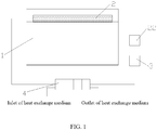
FIG. 1 is a structural schematic diagram of a thermal management device mounted on a battery pack according to an embodiment of the present disclosure; -
FIG. 2 is an explosive view of a heat exchange assembly and the battery pack inFIG. 1 ; -
FIG. 3 is a structural schematic diagram of a heat exchange assembly mounted on the battery pack inFIG. 1 ; -
FIG. 4 is a perspective view of a heat exchange assembly inFIG. 1 ; -
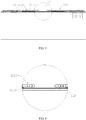
FIG. 5 is a perspective view of a heat exchange assembly mounted on a battery pack according to an embodiment of the present disclosure; and -
FIG. 6 is an enlarged view of an area A inFIG. 5 . -
- 1
- - cell;
- 2
- - thermal management loop;
21 - circulation pipe assembly;
211 - heat exchange assembly;
2111 - first guide tube;
2111a - liquid inlet port;
2111b - liquid outlet port;
2112 - second guide tube;
2113 - heat exchange plate;
2113a - separating plate;
212 - heat conductive connector;
2121 - exhaust hole;
22 - liquid storage tank; - 3
- - power component; and
- 4
- - heat exchange member.
- The technical solutions of the present disclosure will be described clearly and in detail in combination with the accompanying drawings. The following described embodiments are merely a part of the embodiments of the present disclosure rather than all of the embodiments. On the basis of the described embodiments, all other embodiments obtained by those skilled in the art without paying creative labor shall fall within the protection scope of the present disclosure.
- It should be understood that the terms that are used in the context of the present disclosure to describe an orientation or position in view of orientations or positions illustrated in drawings, such as "in", "out" and the like, are merely used to explain the present disclosure, but not intended to indicate or hint that the described devices or elements must have a certain orientation, or are constructed and operated in a certain way. Thus, these terms shall not be interpreted as limitations to present disclosure.
- It should be understood that the terms "mounted", "connected to" and "connected with" should be understood in a broad scope, unless other definitely stipulated and defined. For example, the term "connection" can be construed as a fixed connection, a detachable connection or an integrated connection; a mechanical connection or an electrical connection; a direct connection, or an indirect connection through a medium; or an internal connection of two elements. Those skilled in the art can understand the specific meanings of these terms in the present disclosure in combination with specific circumstances.
- In an embodiment, a battery pack includes a battery case and a plurality of
cells 1 arranged in the battery case. The plurality ofcells 1 is stacked, and eachcell 1 includes a top cover, a positive electrode and a negative electrode. On the top cover are disposed a positive electrode terminal, a negative electrode terminal and a vent disposed between the positive electrode terminal and the negative electrode terminal. The positive electrode terminal and the negative electrode terminal are not differentiated from each other in the drawings. The positive electrode terminal and the negative electrode terminal are electrically connected to the positive electrode and the negative electrode (not shown) of thecell 1 through conductive connectors, respectively. The battery case has a shape of cube, which defines a space (or a cavity) fro receiving eachcell 1. When a short circuit, overcharging and the like occur in the battery pack, the heat generated by thecell 1 greatly exceeds a normal value, resulting in a thermal runaway. - In embodiments shown in
FIG. 1 ,FIG. 3 ,FIG. 5 and FIG. 6 , the thermal management device includes athermal management loop 2 attached to eachcell 1, aheat exchange member 4 communicated with thethermal management loop 2, and a power component 3 connected between thethermal management loop 2 and theheat exchange member 4. Thethermal management loop 2 at least partially covers a vent on the top of eachcell 1. A heat exchange medium having a fire-extinguishing function is provided within thethermal management loop 2. Thethermal management loop 2 can be damaged when the thermal runaway occurs in any one ofcells 1, such that the heat exchange medium flows into an explosion-proof port of thecell 1. During the operation of the battery pack, when a temperature of thecell 1 of the battery pack is greater than a preset threshold value, thethermal management loop 2 cools eachcell 1 efficiently with theheat exchange member 4 and the power component 3. Similarly, when the temperature of thecell 1 of the battery pack is lower than a preset threshold value, thethermal management loop 2 heats eachcell 1 efficiently with theheat exchange member 4 and the power component 3, in order to ensure the operation ofcells 1 at the normal temperature and normal run of vehicles. Thecell 1 of the battery pack, which is subjected to the thermal runaway, can generate a huge amount of gas with high temperature and high pressure, which can break through the vent. In this way, the gas with high temperature and high pressure can damage pipes in thethermal management loop 2 covering the vent, and thus the heat exchange medium in thethermal management loop 2 that is damaged by the gas with high temperature, under the force of gravity, flows into thecell 1 subjected to the thermal runaway through the explosion-proof port. Since the heat exchange medium in thethermal management loop 2 has a fire-extinguishing function, the heat exchange medium flowing into thecell 1 subjected to the thermal runaway can effectively prohibit a propagation of fire, thereby preventingadjacent cells 1 from being affected. Such a configuration can perform a thermal management, i.e., efficiently cooling and heating thecell 1. When the thermal runaway occurs in thecell 1, the gas with high temperature generated by thecell 1 subjected to the thermal runaway can break thethermal management loop 2, and thus the heat exchange medium with the fire-extinguishing function in thethermal management loop 2 flows into thecell 1 subjected to the thermal runaway, thereby extinguishing the fire and preventing theadjacent cells 1 from being affected. The thermal management device has characters of thermal management and the thermal runaway propagation prohibition. - The heat exchange medium is selected from materials having anti-flaming, cooling properties and the like, and simultaneously being able to exchange heat with the
cell 1, such as halogenated hydrocarbon, phosphate, or hydrofluoroether. In the present embodiment, in order to extinguish fire quickly and improve security, the heat exchange medium is a fluorinated liquid, which has a boiling point in a range of 60°C to 120°C. When the fluorinated liquid flows into thecell 1 through the explosion-proof port, thecell 1 can be cooled by transferring the heat to boil the fluorinated liquid, thereby diminishing the influence onadjacent cells 1. At the same time, the fluorinated liquid is boiled to generate a huge amount of gas during a phase transition, which can further decrease a temperature of exhaust gas of thecell 1, thereby increasing the security of the battery pack. In addition, the gas generated by the fluorinated liquid during the phase transition also can isolate the air, which further improves the prohibitive effect on the thermal runaway propagation when the cell 1is subjected to the thermal runaway. - In the present embodiment, the
heat exchange member 4 is a heat exchanger, and the power component 3 is a circulation water pump. Theheat exchange member 4 and thethermal management loop 2 can be connected to each other in any connection manner known in the related art, which is not specifically limited herein, as long as the heat exchange and circulation of the heat exchange medium are guaranteed. - In the present embodiment, in order to automate the
heat exchange member 4, theheat exchange member 4 is electrically connected to both a temperature sensor and a controller. The temperature sensor is configured to detect a change of temperature of thecell 1 in the battery pack and communicate with the controller. When the temperature of thecell 1 is higher than a preset temperature, a signal is transmitted to and received by the controller, and the controller controls the heat exchanger to perform a cooling process so as to cool thecell 1. When the temperature of thecell 1 is lower than a preset temperature, a signal is transmitted to and received by the controller, and the controller controls the heat exchanger to perform a heating process for heating thecell 1 with the heat exchange medium. A connection between theheat exchange member 4 and the temperature sensor as well as a connection between theheat exchange member 4 and the controller are known in the related art and are not specifically limited herein. - As shown in
FIG. 1 , acirculation pipe assembly 21 can directly store the heat exchange medium, in order to achieve a better heat exchange effect and ensure a sufficient amount of the heat exchange medium flowing into thecell 1 that is subjected to the thermal runaway at the same time. In the present embodiment, thethermal management loop 2 includes thecirculation pipe assembly 21 attached to eachcell 1 and aliquid storage tank 22 configured to store the heat exchange medium. Thecirculation pipe assembly 21 at least partially covers a part of the vent of eachcell 1. The heat exchange medium is provided within thecirculation pipe assembly 21. In addition, theliquid storage tank 22, the power component 3 and theheat exchange member 4 are in communication with each other. - As shown in
FIG. 2 ,FIG. 3 andFIG. 5 , thecirculation pipe assembly 21 includes a heatconductive connector 212 and aheat exchange assembly 211 attached to eachcell 1. Theheat exchange assembly 211 is connected to eachcell 1 through the heatconductive connector 212 and completely covers the entire vent. In the present embodiment, in order to guarantee an smooth and unhampered exhaust of gas through the vent and enhance the security of the battery pack, theheat exchange assembly 211 covers a part of the vent of eachcell 1 and is provided with aliquid inlet port 2111a and aliquid outlet port 2111b. Theheat exchange assembly 211 is attached to thecell 1, e.g., being fixed to thecell 1 through a bolt or being clamped to thecell 1. In order to connect theheat exchange assembly 211 and thecell 1 together conveniently and steadily, in an embodiment, theheat exchange assembly 211 is connected to eachcell 1 through the heatconductive connector 212 and performs the thermal management to eachcell 1 through heatconductive connector 211. - In the present embodiment above, the
liquid storage tank 22, the power component 3 and theheat exchange assembly 4 are communicated with each other in any manner known in the related art, which is not specifically limited herein, as long as a normal circulation of the heat exchange medium in thecirculation assembly 21 can be guaranteed. - As shown in
FIG. 2 to FIG. 5 , a heat exchange body of theheat exchange assembly 211 has a shape of pipe. In the present embodiment, in order to enlarge a heat exchange area, theheat exchange assembly 211 includes a plurality ofheat exchange plates 2113 that enlarges a contacting area between the heat exchange medium and thecell 1, thereby increasing a heat exchange efficiency. The plurality ofheat exchange plates 2113 is connected to eachcell 1 through the heatconductive connector 212. - The
heat exchange plate 2113 is made of a material having a lower melting point such that theheat exchange plate 2113 can be broken by the high temperature gas released by thecell 1 within the shortest time when thecell 1 is subjected to the thermal runaway. In an embodiment, theheat exchange plate 2113 can be made of an aluminum alloy material or a magnesium alloy material. In the present embodiment, theheat exchange plate 2113 is made of an aluminum alloy material to reduce the cost. - As shown in
FIG. 2 , the heatconductive connector 212 can be a heat conductive adhesive, and theheat exchange assembly 211 is adhered to a surface of thecell 1 through the heat conductive adhesive. In the present embodiment, in order to increase the heat conductive area and facilitate the adhering of theheat exchange assembly 211 to thecell 1 simultaneously, the heatconductive connector 212 can be a heat exchange adhesive plate. The heat exchange adhesive plate can directly be adhered between theheat exchange plates 2113 and thecell 1. In order to prevent the heat conductive adhesive plate from sealing and covering the vent and blocking the exhaust of gas through the vent,exhaust holes 2121 corresponding to vents of thecell 1 are provided in the heat conductive adhesive plate, and a size of theexhaust hole 2121 is not smaller than a size of the vent. In an embodiment, the size of theexhaust hole 2121 is the same as that of the vent. - As shown in
FIG. 2 to FIG. 4 , in order to perform a thermal management of the plurality ofheat exchange plates 2113, theheat exchange assembly 211 further includes afirst guide tube 2111 and asecond guide tube 2112. Thefirst guide tube 2111 is provided with a firstliquid inlet port 2111a and aliquid outlet port 2111b, the plurality ofheat exchange plate 2113 is communicated with theliquid storage tank 22 through thefirst guide tube 2111 and thesecond guide tube 2112. The plurality ofheat exchange plate 2113 is connected to each other in parallel and connected between thefirst guide tube 2111 and thesecond guide tube 2112. In the present embodiment, in order to decrease the amount of the heat exchange medium in both theheat exchange plate 2113 and theliquid storage tank 22 and simplify the communication between theheat exchange plates 2113, the plurality ofheat exchange plate 2113 is spaced apart from each other and connected in series between thefirst guide tube 2111 and thesecond guide tube 2112, and eachheat exchange plate 2113 covers a part of the vent of eachcell 1. - An angle can be enclosed between a direction in which the
heat exchange plate 2113 extends and a direction in which thecells 1 are stacked. In the embodiment shown inFIG. 2 , in order to assembly theheat exchange plate 2113 conveniently, theheat exchange plate 2113 extends in the direction in which thecells 1 are stacked. A number of theheat exchange plates 2113 can be greater than one, e.g., two, three, four, five and so on. For example, twoheat exchange plates 2113 are provided to guarantee the thermal management of the battery pack and reduce the cost at the same time. In an embodiment, the vent of thecell 1 is arranged in the middle of the top cover, and the twoheat exchange plates 2113 are oppositely disposed at two sides of a center line of the vent and respectively cover two ends of the vent, such that the heat exchange medium in the twoheat exchange plates 2113 can flow into thecell 1 that is subjected to the thermal runaway, thereby improving the security. - As shown in
FIG. 4 to FIG. 6 , a cavity structure provided within theheat exchange plate 2113 can be as an integral portion, i.e., theheat exchange plate 2113 has only one flow channel. In the present embodiment, in order to improve the heat exchange effect of the heat thermal management device, a plurality of separatingplates 2113a is provided within the cavity structure of theheat exchange plate 2113 to space the cavity structure of theheat exchange plate 2113 into a plurality of flow channels, and the plurality of separatingplates 2113a is uniformly-spaced along a direction perpendicular to the direction in which thecells 1 are stacked. - The present disclosure further provides a battery pack including the thermal management device according to any one of the above embodiments.
- The battery pack provided in embodiments of the present disclosure has same advantages as the above thermal management device, which will not be repeated herein.
- It should be understood that the embodiments discussed above are merely used to illustrate, but not intended to limit the technical solutions of the present disclosure. Although the present disclosure is described in detail with reference to the embodiments, those skilled in the art still can modify the technical solutions in the above embodiments in various manners, or equivalently replace a part of or all of technical features. Such modifications or equivalent replacement without departing from the principles of the present disclosure should be included in the scope of protection of the present disclosure.
Claims (11)
- A thermal management device applied in a battery pack, the battery pack comprising a case and a plurality of cells (1) received in the case, characterized in that the thermal management device comprises:a thermal management loop (2) attached to each of the plurality of cells (1) and at least partially covering a part of a vent of each of the plurality of cells (1);a heat exchange member (4) communicating with the thermal management loop (2); anda power component (3) connected between the thermal management loop (2) and the heat exchange member (4),wherein a heat exchange medium with a fire-extinguishing function is provided within the thermal management loop (2), and the thermal management loop (2) is broken in a condition where at least one of the plurality of cells (1) is subjected to a thermal runaway such that the heat exchange medium flows into an explosion-proof port of the at least one of the plurality of cells (1) subjected to the thermal runaway.
- The thermal management device according to claim 1, characterized in that the thermal management loop (2) comprises:a circulation pipe assembly (21) attached to each of the plurality of cells (1) and at least partially covering a part of the vent of each of the plurality of cells (1), wherein the heat exchange medium is provided within the circulation pipe assembly (21); anda liquid storage tank (22) configured to store the heat exchange medium;wherein the liquid storage tank (22), the power component (3) and the heat exchange member (4) are communicated with each other.
- The thermal management device according to claim 2, characterized in that the circulation pipe assembly (21) comprises:a heat exchange assembly (211) attached to each of the plurality of cells (1), the heat exchange assembly (211) at least partially covering a part of the vent of each of the plurality of cells (1) and being provided with a liquid inlet port (2111a) and a liquid outlet port (2111b); anda heat conductive connector (212) through which the heat exchange assembly (211) is connected to each of the plurality of cells (1).
- The thermal management device according to claim 3, characterized in that the heat exchange assembly (211) comprises:a first guide tube (2111) provided with the liquid inlet port (2111a) and the liquid outlet port (2111b);a second guide tube (2112); anda plurality of heat exchange plates (2113) connected to each of the plurality of cells (1) through the heat conductive connector (212) and configured as a cavity structure for receiving the heat exchange medium;wherein the plurality of heat exchange plates (2113) is communicated between the first guide tube (2111) and the second guide tube (2112), and the plurality of heat exchange plates (2113) covers a part of the vent of each of the plurality of cells (1); and the plurality of heat exchange plates (2113) is broken in the condition where the at least one of the plurality of cells (1) is subjected to the thermal runaway such that the heat exchange medium flows into the explosion-proof port of the at least one of the plurality of cells (1) subjected to the thermal runaway.
- The thermal management device according to claim 4, characterized in that the plurality of heat exchange plates (2113) is spaced apart from each other and connected in series, and the plurality of heat exchange plates (2113) is arranged between and communicated with the first guide tube (2111) and the second guide tube (2112).
- The thermal management device according to claim 4, wherein a plurality of separating plates (2113a) is provided within the cavity structure of the plurality of heat exchange plates (2113) and configured to separate the cavity structure into a plurality of flow channels.
- The thermal management device according to claim 4, wherein the plurality of heat exchange plates (2113) is made of an aluminum alloy material or a magnesium alloy material.
- The thermal management device according to any one of claims 3-7, characterized in that the heat conductive connector (212) is a heat conductive adhesive plate.
- The thermal management device according to claim 8, characterized in that the heat conductive adhesive plate is provided with a plurality of exhaust holes (2121) each corresponding to the vent of each of the plurality of cells (1).
- A battery pack, characterized in that the battery comprises the thermal management device according to any one of claims 1-9.
- A vehicle, characterized in that the vehicle comprises the battery pack according to claim 10.
Applications Claiming Priority (1)
| Application Number | Priority Date | Filing Date | Title |
|---|---|---|---|
| CN201822236759.6U CN209071461U (en) | 2018-12-28 | 2018-12-28 | Heat management device and battery pack |
Publications (1)
| Publication Number | Publication Date |
|---|---|
| EP3675218A1 true EP3675218A1 (en) | 2020-07-01 |
Family
ID=67102423
Family Applications (1)
| Application Number | Title | Priority Date | Filing Date |
|---|---|---|---|
| EP19210621.9A Pending EP3675218A1 (en) | 2018-12-28 | 2019-11-21 | Thermal management device and battery pack |
Country Status (4)
| Country | Link |
|---|---|
| US (1) | US11133543B2 (en) |
| EP (1) | EP3675218A1 (en) |
| CN (1) | CN209071461U (en) |
| WO (1) | WO2020135073A1 (en) |
Cited By (17)
| Publication number | Priority date | Publication date | Assignee | Title |
|---|---|---|---|---|
| CN112652858A (en) * | 2021-01-18 | 2021-04-13 | 中国第一汽车股份有限公司 | Battery module, battery assembly and electric motor car that delay thermal runaway |
| EP3965211A4 (en) * | 2020-07-10 | 2022-03-09 | Contemporary Amperex Technology Co., Limited | BATTERY BOX BODY, BATTERY, ELECTRICAL DEVICE, AND BATTERY PREPARATION METHOD AND DEVICE |
| KR20220104219A (en) * | 2020-09-30 | 2022-07-26 | 컨템포러리 엠퍼렉스 테크놀로지 씨오., 리미티드 | Batteries, devices, battery manufacturing methods and battery manufacturing devices |
| EP4053972A4 (en) * | 2019-10-31 | 2023-06-21 | Panasonic Intellectual Property Management Co., Ltd. | ENERGY STORAGE MODULE |
| CN116547856A (en) * | 2022-06-13 | 2023-08-04 | 宁德时代新能源科技股份有限公司 | Thermal management component, thermal management system, battery and electricity utilization device |
| US11791518B2 (en) | 2020-07-10 | 2023-10-17 | Contemporary Amperex Technology Co., Limited | Battery, power consumption device, method and device for preparing a battery |
| EP4064422A4 (en) * | 2020-09-30 | 2023-10-25 | Contemporary Amperex Technology Co., Limited | BATTERY, DEVICE AND METHOD FOR MANUFACTURING BATTERY AND MANUFACTURING APPARATUS |
| EP4175017A3 (en) * | 2021-10-05 | 2023-11-01 | Samsung SDI Co., Ltd. | Cell cooling cover for a battery module |
| US11901555B2 (en) | 2021-07-30 | 2024-02-13 | Contemporary Amperex Technology Co., Limited | Battery module, battery pack, and electric apparatus |
| US11955654B2 (en) | 2020-07-10 | 2024-04-09 | Contemporary Amperex Technology Co., Limited | Battery, and related device, preparation method and preparation apparatus thereof |
| US11990592B2 (en) | 2020-11-17 | 2024-05-21 | Contemporary Amperex Technology Co., Limited | Battery, apparatus using battery, and manufacturing method and manufacturing device of battery |
| US12034176B2 (en) | 2020-09-30 | 2024-07-09 | Contemporary Amperex Technology Co., Limited | Battery, apparatus, and preparation method and preparation apparatus of battery |
| US12068468B2 (en) | 2020-12-24 | 2024-08-20 | Contemporary Amperex Technology Co., Limited | Battery module and manufacturing method and device thereof, battery pack, and power consumption apparatus |
| US12113162B2 (en) | 2020-04-30 | 2024-10-08 | Contemporary Amperex Technology Co., Limited | Battery comprising first-type battery cell group and second-type battery cell group which are connected in series, apparatus, and method and device for manufacturing battery |
| US12132217B2 (en) | 2020-07-29 | 2024-10-29 | Contemporary Amperex Technology Co., Limited | Battery module, battery pack, apparatus, and method and device for manufacturing battery module |
| US12183943B2 (en) | 2020-07-10 | 2024-12-31 | Contemporary Amperex Technology (Hong Kong) Limited | Battery, power consumption device, method and device for preparing a battery |
| US12212015B2 (en) | 2020-07-10 | 2025-01-28 | Contemporary Amperex Technology (Hong Kong) Limited | Battery, and related device, preparation method and preparation apparatus thereof |
Families Citing this family (38)
| Publication number | Priority date | Publication date | Assignee | Title |
|---|---|---|---|---|
| CN209071461U (en) * | 2018-12-28 | 2019-07-05 | 宁德时代新能源科技股份有限公司 | Heat management device and battery pack |
| US20210154501A1 (en) * | 2019-11-22 | 2021-05-27 | The Boeing Company | Fire suppression for additively manufactured article |
| CN211376746U (en) | 2020-02-21 | 2020-08-28 | 宁德时代新能源科技股份有限公司 | Battery pack and device |
| US20230223647A1 (en) * | 2020-04-22 | 2023-07-13 | Volvo Truck Corporation | An electric energy storage system for a vehicle |
| CN111509163A (en) * | 2020-05-25 | 2020-08-07 | 重庆金康动力新能源有限公司 | Battery pack with fire extinguishing function |
| CN111682142A (en) * | 2020-06-30 | 2020-09-18 | 上海豫源电力科技有限公司 | A battery pack with fire extinguishing function and control method thereof |
| CN111682256A (en) * | 2020-06-30 | 2020-09-18 | 上海豫源电力科技有限公司 | Lithium-ion battery with fire fighting function and its management system and control method |
| HUE062373T2 (en) * | 2020-07-10 | 2023-10-28 | Contemporary Amperex Technology Co Ltd | Battery and related apparatus thereof, preparation method therefor, and preparation device therefor |
| KR102730813B1 (en) * | 2020-07-10 | 2024-11-14 | 컨템포러리 엠퍼렉스 테크놀로지 (홍콩) 리미티드 | Battery, electric device, method for manufacturing battery and device |
| CN113937384B (en) * | 2020-07-14 | 2023-07-07 | 北京好风光储能技术有限公司 | Energy storage battery system |
| CN212810495U (en) * | 2020-08-21 | 2021-03-26 | 宁德时代新能源科技股份有限公司 | A battery and electrical equipment |
| EP4009433B1 (en) | 2020-10-19 | 2023-07-12 | Jiangsu Contemporary Amperex Technology Limited | Battery, electric apparatus, and battery manufacturing method and device |
| EP4071911B1 (en) | 2020-10-19 | 2024-07-17 | Jiangsu Contemporary Amperex Technology Limited | Battery, power consuming device and method for producing battery |
| WO2022082387A1 (en) | 2020-10-19 | 2022-04-28 | 江苏时代新能源科技有限公司 | Battery, electrical device, and method and device for preparing battery |
| JP7580575B2 (en) * | 2020-10-19 | 2024-11-11 | ジアンス・コンテンポラリー・アンプレックス・テクノロジー・リミテッド | Battery, electric device, and battery manufacturing method and device |
| JP7546755B2 (en) | 2020-10-19 | 2024-09-06 | ジアンス・コンテンポラリー・アンプレックス・テクノロジー・リミテッド | Battery, power utilization device, and battery preparation method and equipment |
| JP7350213B2 (en) | 2020-10-19 | 2023-09-25 | ジアンス・コンテンポラリー・アンプレックス・テクノロジー・リミテッド | Batteries, power consumption devices, battery manufacturing methods and devices |
| CN112072046B (en) * | 2020-10-19 | 2022-12-27 | 江苏时代新能源科技有限公司 | Battery, electric device, method and equipment for preparing battery |
| CN112018302B (en) * | 2020-10-19 | 2021-05-04 | 江苏时代新能源科技有限公司 | Battery, electric device, method and equipment for preparing battery |
| CN112490578B (en) * | 2020-11-11 | 2021-11-23 | 华南理工大学 | Power battery module |
| CN112490529B (en) * | 2020-11-13 | 2023-02-24 | 重庆金康动力新能源有限公司 | Cooling pipe, cooling system, battery package and car |
| CN112531231B (en) * | 2020-12-01 | 2022-04-01 | 清华大学 | Passive Safety Management Battery Pack |
| CN112604206B (en) * | 2020-12-04 | 2022-04-26 | 重庆金康动力新能源有限公司 | Fire extinguishing system and control method for battery pack |
| CN112704832A (en) * | 2020-12-29 | 2021-04-27 | 长城汽车股份有限公司 | Battery box and battery package |
| EP4092818B1 (en) | 2021-03-31 | 2024-01-10 | Contemporary Amperex Technology Co., Limited | Battery box body, battery, electric device, and method for preparing box body |
| CN113410588A (en) * | 2021-06-18 | 2021-09-17 | 陕西奥林波斯电力能源有限责任公司 | Pole and large-capacity battery using same |
| CN113594581B (en) * | 2021-08-03 | 2023-06-30 | 广州小鹏汽车科技有限公司 | Battery pack and electric automobile |
| CN115911743B (en) * | 2021-08-18 | 2023-12-15 | 宁德时代新能源科技股份有限公司 | Battery and electricity utilization device |
| CN113745695B (en) * | 2021-08-27 | 2023-10-27 | 中国第一汽车股份有限公司 | Fire extinguishing pipe assembly, battery thermal management device, battery system and electric vehicle |
| EP4235922A4 (en) * | 2022-01-12 | 2024-04-17 | Contemporary Amperex Technology Co., Limited | BOX FOR BATTERY, BATTERY, POWER CONSUMPTION DEVICE AND METHOD AND DEVICE FOR PRODUCING A BOX |
| US12263718B2 (en) | 2022-03-10 | 2025-04-01 | Carrier Corporation | Transport refrigeration system with battery temperature control |
| CN114597544A (en) * | 2022-03-16 | 2022-06-07 | 中创新航科技股份有限公司 | Battery pack |
| CN114927810B (en) * | 2022-04-11 | 2024-04-09 | 中国第一汽车股份有限公司 | Multifunctional battery cover plate, cover plate thickness determining method and power battery system |
| CN115939579A (en) * | 2022-12-19 | 2023-04-07 | 浙江运达风电股份有限公司 | A harmonica tube for preventing thermal runaway, method and device for preventing thermal runaway, and storage medium |
| CN115882149B (en) * | 2023-02-22 | 2023-05-23 | 深圳市柯讯科技有限公司 | Fireproof and explosion-proof battery pack |
| CN117650310A (en) * | 2023-12-18 | 2024-03-05 | 江苏正力新能电池技术有限公司 | A thermal safety system and power battery |
| CN117673562A (en) * | 2023-12-18 | 2024-03-08 | 江苏正力新能电池技术有限公司 | A power battery, thermal management cycle control system and method |
| CN119764740A (en) * | 2024-07-05 | 2025-04-04 | 北京车和家汽车科技有限公司 | Battery pack and vehicle |
Citations (3)
| Publication number | Priority date | Publication date | Assignee | Title |
|---|---|---|---|---|
| US20100136391A1 (en) * | 2009-09-12 | 2010-06-03 | Tesla Motors, Inc. | Active Thermal Runaway Mitigation System for Use Within a Battery Pack |
| CN103779629A (en) * | 2014-01-22 | 2014-05-07 | 浙江吉利控股集团有限公司 | Battery cooling system having extinguishing function |
| EP3333932A1 (en) * | 2016-12-06 | 2018-06-13 | Samsung SDI Co., Ltd. | Battery system |
Family Cites Families (9)
| Publication number | Priority date | Publication date | Assignee | Title |
|---|---|---|---|---|
| US6407533B1 (en) * | 2000-10-31 | 2002-06-18 | Alcatel Usa Sourcing, Lp | Battery temperature stabilization system and method |
| CN101841072A (en) * | 2010-02-09 | 2010-09-22 | 北汽福田汽车股份有限公司 | Liquid cooling system of storage battery and liquid cooling method of storage battery |
| US9537124B2 (en) * | 2011-03-23 | 2017-01-03 | Ford Global Technologies, Llc | Variable insulating battery pack system and method |
| US10427491B2 (en) * | 2011-09-28 | 2019-10-01 | Tesla, Inc. | Thermal management system with heat exchanger blending valve |
| US10522845B2 (en) * | 2011-09-28 | 2019-12-31 | Tesla, Inc. | Battery centric thermal management system utilizing a heat exchanger blending valve |
| CN103779632B (en) * | 2014-01-22 | 2017-01-04 | 浙江吉利控股集团有限公司 | There is the battery cooling system of fire-extinguishing function concurrently |
| US10431860B2 (en) * | 2015-02-23 | 2019-10-01 | Ford Global Technologies, Llc | Cold plate assembly for electrified vehicle batteries |
| CN207977389U (en) * | 2018-01-29 | 2018-10-16 | 浙江美都海创锂电科技有限公司 | A kind of safety anti-explosive rectangular cell module |
| CN209071461U (en) * | 2018-12-28 | 2019-07-05 | 宁德时代新能源科技股份有限公司 | Heat management device and battery pack |
-
2018
- 2018-12-28 CN CN201822236759.6U patent/CN209071461U/en active Active
-
2019
- 2019-11-20 US US16/689,143 patent/US11133543B2/en active Active
- 2019-11-21 EP EP19210621.9A patent/EP3675218A1/en active Pending
- 2019-12-12 WO PCT/CN2019/124865 patent/WO2020135073A1/en not_active Ceased
Patent Citations (3)
| Publication number | Priority date | Publication date | Assignee | Title |
|---|---|---|---|---|
| US20100136391A1 (en) * | 2009-09-12 | 2010-06-03 | Tesla Motors, Inc. | Active Thermal Runaway Mitigation System for Use Within a Battery Pack |
| CN103779629A (en) * | 2014-01-22 | 2014-05-07 | 浙江吉利控股集团有限公司 | Battery cooling system having extinguishing function |
| EP3333932A1 (en) * | 2016-12-06 | 2018-06-13 | Samsung SDI Co., Ltd. | Battery system |
Cited By (26)
| Publication number | Priority date | Publication date | Assignee | Title |
|---|---|---|---|---|
| EP4053972A4 (en) * | 2019-10-31 | 2023-06-21 | Panasonic Intellectual Property Management Co., Ltd. | ENERGY STORAGE MODULE |
| US12272780B2 (en) | 2020-04-30 | 2025-04-08 | Contemporary Amperex Technology Co., Limited | Battery module, apparatus, battery pack, and method and device for manufacturing battery module |
| US12113162B2 (en) | 2020-04-30 | 2024-10-08 | Contemporary Amperex Technology Co., Limited | Battery comprising first-type battery cell group and second-type battery cell group which are connected in series, apparatus, and method and device for manufacturing battery |
| US11967725B2 (en) | 2020-07-10 | 2024-04-23 | Contemporary Amperex Technology Co., Limited | Case of battery, battery, power consumption device, and method and device for preparing battery |
| US12212015B2 (en) | 2020-07-10 | 2025-01-28 | Contemporary Amperex Technology (Hong Kong) Limited | Battery, and related device, preparation method and preparation apparatus thereof |
| US11450916B2 (en) | 2020-07-10 | 2022-09-20 | Contemporary Amperex Technology Co., Limited | Case of battery, battery, power consumption device, and method and device for preparing battery |
| US12407060B2 (en) | 2020-07-10 | 2025-09-02 | Contemporary Amperex Technology (Hong Kong) Limited | Battery, power consumption device, method and device for preparing a battery |
| US11791518B2 (en) | 2020-07-10 | 2023-10-17 | Contemporary Amperex Technology Co., Limited | Battery, power consumption device, method and device for preparing a battery |
| US12183943B2 (en) | 2020-07-10 | 2024-12-31 | Contemporary Amperex Technology (Hong Kong) Limited | Battery, power consumption device, method and device for preparing a battery |
| EP3965211A4 (en) * | 2020-07-10 | 2022-03-09 | Contemporary Amperex Technology Co., Limited | BATTERY BOX BODY, BATTERY, ELECTRICAL DEVICE, AND BATTERY PREPARATION METHOD AND DEVICE |
| US11955654B2 (en) | 2020-07-10 | 2024-04-09 | Contemporary Amperex Technology Co., Limited | Battery, and related device, preparation method and preparation apparatus thereof |
| US12132217B2 (en) | 2020-07-29 | 2024-10-29 | Contemporary Amperex Technology Co., Limited | Battery module, battery pack, apparatus, and method and device for manufacturing battery module |
| EP4064422A4 (en) * | 2020-09-30 | 2023-10-25 | Contemporary Amperex Technology Co., Limited | BATTERY, DEVICE AND METHOD FOR MANUFACTURING BATTERY AND MANUFACTURING APPARATUS |
| EP4064435A4 (en) * | 2020-09-30 | 2024-04-24 | Contemporary Amperex Technology Co., Limited | Battery, device, and preparation method and preparation device for battery |
| KR20220104219A (en) * | 2020-09-30 | 2022-07-26 | 컨템포러리 엠퍼렉스 테크놀로지 씨오., 리미티드 | Batteries, devices, battery manufacturing methods and battery manufacturing devices |
| US12002984B2 (en) | 2020-09-30 | 2024-06-04 | Contemporary Amperex Technology Co., Limited | Battery, apparatus, and preparation method and preparation apparatus of battery |
| US12034176B2 (en) | 2020-09-30 | 2024-07-09 | Contemporary Amperex Technology Co., Limited | Battery, apparatus, and preparation method and preparation apparatus of battery |
| US12176509B2 (en) | 2020-09-30 | 2024-12-24 | Contemporary Amperex Technology (Hong Kong) Limited | Battery, apparatus, and preparation method and preparation apparatus of battery |
| US11990592B2 (en) | 2020-11-17 | 2024-05-21 | Contemporary Amperex Technology Co., Limited | Battery, apparatus using battery, and manufacturing method and manufacturing device of battery |
| US12068468B2 (en) | 2020-12-24 | 2024-08-20 | Contemporary Amperex Technology Co., Limited | Battery module and manufacturing method and device thereof, battery pack, and power consumption apparatus |
| CN112652858B (en) * | 2021-01-18 | 2022-06-10 | 中国第一汽车股份有限公司 | Battery module, battery assembly and electric motor car that delay thermal runaway |
| CN112652858A (en) * | 2021-01-18 | 2021-04-13 | 中国第一汽车股份有限公司 | Battery module, battery assembly and electric motor car that delay thermal runaway |
| US11901555B2 (en) | 2021-07-30 | 2024-02-13 | Contemporary Amperex Technology Co., Limited | Battery module, battery pack, and electric apparatus |
| EP4175017A3 (en) * | 2021-10-05 | 2023-11-01 | Samsung SDI Co., Ltd. | Cell cooling cover for a battery module |
| US12548823B2 (en) | 2021-10-05 | 2026-02-10 | Samsung Sdi Co., Ltd. | Cell cooling cover for a battery module |
| CN116547856A (en) * | 2022-06-13 | 2023-08-04 | 宁德时代新能源科技股份有限公司 | Thermal management component, thermal management system, battery and electricity utilization device |
Also Published As
| Publication number | Publication date |
|---|---|
| WO2020135073A1 (en) | 2020-07-02 |
| US20200212526A1 (en) | 2020-07-02 |
| US11133543B2 (en) | 2021-09-28 |
| CN209071461U (en) | 2019-07-05 |
Similar Documents
| Publication | Publication Date | Title |
|---|---|---|
| US11133543B2 (en) | Thermal management device and battery pack | |
| CN104795606B (en) | liquid-cooled battery pack system | |
| CN112531231B (en) | Passive Safety Management Battery Pack | |
| CN219086086U (en) | Current collector, thermal management assembly, battery and electricity utilization device | |
| CN212810495U (en) | A battery and electrical equipment | |
| CN112086604A (en) | Battery, electrical equipment, method and device for preparing battery | |
| KR20180013460A (en) | Battery apparatus | |
| WO2023010516A1 (en) | Case for battery, battery, power consuming device, and method and device for preparing battery | |
| WO2022082389A1 (en) | Battery, power utilization device, and battery preparation method and apparatus | |
| JP7331151B2 (en) | Battery modules, battery racks containing the same, and power storage devices | |
| CN110311189A (en) | Battery modules, battery packs, electric vehicles and grid systems | |
| CN103138027A (en) | High thermal conductivity battery components | |
| WO2010132753A1 (en) | Battery pack heat exchanger, systems, and methods | |
| WO2020192196A1 (en) | Battery module and power battery pack | |
| CN112018302A (en) | Battery, electric device, method and equipment for preparing battery | |
| CN218351654U (en) | Battery pack | |
| CN109301116B (en) | Power battery module with plug cooling plate | |
| KR20220168911A (en) | Battery module, battery pack comprising the battery module and vehicle comprising the battery pack | |
| WO2022082392A1 (en) | Battery, power consuming apparatus and method and apparatus for producing battery | |
| CN111384465A (en) | battery pack | |
| CN116345017A (en) | Power battery system and new energy vehicles | |
| CN110739425A (en) | vertical lithium battery pack air-cooling type thermal management system and method with high protection level | |
| CN207504058U (en) | A kind of battery box structure | |
| JP2023530784A (en) | Battery housing, battery, power consumption device, battery manufacturing method and device | |
| CN203760591U (en) | Liquid cooling battery pack system |
Legal Events
| Date | Code | Title | Description |
|---|---|---|---|
| PUAI | Public reference made under article 153(3) epc to a published international application that has entered the european phase |
Free format text: ORIGINAL CODE: 0009012 |
|
| STAA | Information on the status of an ep patent application or granted ep patent |
Free format text: STATUS: THE APPLICATION HAS BEEN PUBLISHED |
|
| AK | Designated contracting states |
Kind code of ref document: A1 Designated state(s): AL AT BE BG CH CY CZ DE DK EE ES FI FR GB GR HR HU IE IS IT LI LT LU LV MC MK MT NL NO PL PT RO RS SE SI SK SM TR |
|
| AX | Request for extension of the european patent |
Extension state: BA ME |
|
| XX | Miscellaneous (additional remarks) |
Free format text: THE APPLICANT HAS FILED A TEXT WITH WHICH IT IS INTENDED TO BRING THE TRANSLATION INTO CONFORMITY WITH THE APPLICATION AS FILED (ART. 14(2) EPC). |
|
| STAA | Information on the status of an ep patent application or granted ep patent |
Free format text: STATUS: REQUEST FOR EXAMINATION WAS MADE |
|
| 17P | Request for examination filed |
Effective date: 20210104 |
|
| RBV | Designated contracting states (corrected) |
Designated state(s): AL AT BE BG CH CY CZ DE DK EE ES FI FR GB GR HR HU IE IS IT LI LT LU LV MC MK MT NL NO PL PT RO RS SE SI SK SM TR |
|
| STAA | Information on the status of an ep patent application or granted ep patent |
Free format text: STATUS: EXAMINATION IS IN PROGRESS |
|
| 17Q | First examination report despatched |
Effective date: 20230420 |
|
| RAP1 | Party data changed (applicant data changed or rights of an application transferred) |
Owner name: CONTEMPORARY AMPEREX TECHNOLOGY(HONG KONG) LIMITED |