EP3675217B1 - Battery box and vehicle - Google Patents
Battery box and vehicle Download PDFInfo
- Publication number
- EP3675217B1 EP3675217B1 EP19207854.1A EP19207854A EP3675217B1 EP 3675217 B1 EP3675217 B1 EP 3675217B1 EP 19207854 A EP19207854 A EP 19207854A EP 3675217 B1 EP3675217 B1 EP 3675217B1
- Authority
- EP
- European Patent Office
- Prior art keywords
- battery
- adhesive
- case
- insulating film
- opening
- Prior art date
- Legal status (The legal status is an assumption and is not a legal conclusion. Google has not performed a legal analysis and makes no representation as to the accuracy of the status listed.)
- Active
Links
Images

Classifications
-
- B—PERFORMING OPERATIONS; TRANSPORTING
- B60—VEHICLES IN GENERAL
- B60L—PROPULSION OF ELECTRICALLY-PROPELLED VEHICLES; SUPPLYING ELECTRIC POWER FOR AUXILIARY EQUIPMENT OF ELECTRICALLY-PROPELLED VEHICLES; ELECTRODYNAMIC BRAKE SYSTEMS FOR VEHICLES IN GENERAL; MAGNETIC SUSPENSION OR LEVITATION FOR VEHICLES; MONITORING OPERATING VARIABLES OF ELECTRICALLY-PROPELLED VEHICLES; ELECTRIC SAFETY DEVICES FOR ELECTRICALLY-PROPELLED VEHICLES
- B60L50/00—Electric propulsion with power supplied within the vehicle
- B60L50/50—Electric propulsion with power supplied within the vehicle using propulsion power supplied by batteries or fuel cells
- B60L50/60—Electric propulsion with power supplied within the vehicle using propulsion power supplied by batteries or fuel cells using power supplied by batteries
- B60L50/64—Constructional details of batteries specially adapted for electric vehicles
-
- B—PERFORMING OPERATIONS; TRANSPORTING
- B60—VEHICLES IN GENERAL
- B60R—VEHICLES, VEHICLE FITTINGS, OR VEHICLE PARTS, NOT OTHERWISE PROVIDED FOR
- B60R16/00—Electric or fluid circuits specially adapted for vehicles and not otherwise provided for; Arrangement of elements of electric or fluid circuits specially adapted for vehicles and not otherwise provided for
- B60R16/02—Electric or fluid circuits specially adapted for vehicles and not otherwise provided for; Arrangement of elements of electric or fluid circuits specially adapted for vehicles and not otherwise provided for electric constitutive elements
- B60R16/04—Arrangement of batteries
-
- H—ELECTRICITY
- H01—ELECTRIC ELEMENTS
- H01M—PROCESSES OR MEANS, e.g. BATTERIES, FOR THE DIRECT CONVERSION OF CHEMICAL ENERGY INTO ELECTRICAL ENERGY
- H01M50/00—Constructional details or processes of manufacture of the non-active parts of electrochemical cells other than fuel cells, e.g. hybrid cells
- H01M50/10—Primary casings; Jackets or wrappings
- H01M50/131—Primary casings; Jackets or wrappings characterised by physical properties, e.g. gas permeability, size or heat resistance
-
- H—ELECTRICITY
- H01—ELECTRIC ELEMENTS
- H01M—PROCESSES OR MEANS, e.g. BATTERIES, FOR THE DIRECT CONVERSION OF CHEMICAL ENERGY INTO ELECTRICAL ENERGY
- H01M50/00—Constructional details or processes of manufacture of the non-active parts of electrochemical cells other than fuel cells, e.g. hybrid cells
- H01M50/10—Primary casings; Jackets or wrappings
- H01M50/116—Primary casings; Jackets or wrappings characterised by the material
- H01M50/121—Organic material
-
- H—ELECTRICITY
- H01—ELECTRIC ELEMENTS
- H01M—PROCESSES OR MEANS, e.g. BATTERIES, FOR THE DIRECT CONVERSION OF CHEMICAL ENERGY INTO ELECTRICAL ENERGY
- H01M50/00—Constructional details or processes of manufacture of the non-active parts of electrochemical cells other than fuel cells, e.g. hybrid cells
- H01M50/10—Primary casings; Jackets or wrappings
- H01M50/116—Primary casings; Jackets or wrappings characterised by the material
- H01M50/124—Primary casings; Jackets or wrappings characterised by the material having a layered structure
-
- H—ELECTRICITY
- H01—ELECTRIC ELEMENTS
- H01M—PROCESSES OR MEANS, e.g. BATTERIES, FOR THE DIRECT CONVERSION OF CHEMICAL ENERGY INTO ELECTRICAL ENERGY
- H01M50/00—Constructional details or processes of manufacture of the non-active parts of electrochemical cells other than fuel cells, e.g. hybrid cells
- H01M50/10—Primary casings; Jackets or wrappings
- H01M50/131—Primary casings; Jackets or wrappings characterised by physical properties, e.g. gas permeability, size or heat resistance
- H01M50/133—Thickness
-
- H—ELECTRICITY
- H01—ELECTRIC ELEMENTS
- H01M—PROCESSES OR MEANS, e.g. BATTERIES, FOR THE DIRECT CONVERSION OF CHEMICAL ENERGY INTO ELECTRICAL ENERGY
- H01M50/00—Constructional details or processes of manufacture of the non-active parts of electrochemical cells other than fuel cells, e.g. hybrid cells
- H01M50/20—Mountings; Secondary casings or frames; Racks, modules or packs; Suspension devices; Shock absorbers; Transport or carrying devices; Holders
- H01M50/204—Racks, modules or packs for multiple batteries or multiple cells
- H01M50/207—Racks, modules or packs for multiple batteries or multiple cells characterised by their shape
- H01M50/209—Racks, modules or packs for multiple batteries or multiple cells characterised by their shape adapted for prismatic or rectangular cells
-
- H—ELECTRICITY
- H01—ELECTRIC ELEMENTS
- H01M—PROCESSES OR MEANS, e.g. BATTERIES, FOR THE DIRECT CONVERSION OF CHEMICAL ENERGY INTO ELECTRICAL ENERGY
- H01M2220/00—Batteries for particular applications
- H01M2220/20—Batteries in motive systems, e.g. vehicle, ship, plane
-
- H—ELECTRICITY
- H01—ELECTRIC ELEMENTS
- H01M—PROCESSES OR MEANS, e.g. BATTERIES, FOR THE DIRECT CONVERSION OF CHEMICAL ENERGY INTO ELECTRICAL ENERGY
- H01M50/00—Constructional details or processes of manufacture of the non-active parts of electrochemical cells other than fuel cells, e.g. hybrid cells
- H01M50/10—Primary casings; Jackets or wrappings
- H01M50/116—Primary casings; Jackets or wrappings characterised by the material
- H01M50/117—Inorganic material
- H01M50/119—Metals
-
- Y—GENERAL TAGGING OF NEW TECHNOLOGICAL DEVELOPMENTS; GENERAL TAGGING OF CROSS-SECTIONAL TECHNOLOGIES SPANNING OVER SEVERAL SECTIONS OF THE IPC; TECHNICAL SUBJECTS COVERED BY FORMER USPC CROSS-REFERENCE ART COLLECTIONS [XRACs] AND DIGESTS
- Y02—TECHNOLOGIES OR APPLICATIONS FOR MITIGATION OR ADAPTATION AGAINST CLIMATE CHANGE
- Y02E—REDUCTION OF GREENHOUSE GAS [GHG] EMISSIONS, RELATED TO ENERGY GENERATION, TRANSMISSION OR DISTRIBUTION
- Y02E60/00—Enabling technologies; Technologies with a potential or indirect contribution to GHG emissions mitigation
- Y02E60/10—Energy storage using batteries
-
- Y—GENERAL TAGGING OF NEW TECHNOLOGICAL DEVELOPMENTS; GENERAL TAGGING OF CROSS-SECTIONAL TECHNOLOGIES SPANNING OVER SEVERAL SECTIONS OF THE IPC; TECHNICAL SUBJECTS COVERED BY FORMER USPC CROSS-REFERENCE ART COLLECTIONS [XRACs] AND DIGESTS
- Y02—TECHNOLOGIES OR APPLICATIONS FOR MITIGATION OR ADAPTATION AGAINST CLIMATE CHANGE
- Y02T—CLIMATE CHANGE MITIGATION TECHNOLOGIES RELATED TO TRANSPORTATION
- Y02T10/00—Road transport of goods or passengers
- Y02T10/60—Other road transportation technologies with climate change mitigation effect
- Y02T10/70—Energy storage systems for electromobility, e.g. batteries
Definitions
- the present invention relates to the field of battery technology, and particularly relates to a battery box and a vehicle.
- Related technologies are known from DE 10 2013 204670 B3 , DE 10 2014 211821 A1 and US 2010/136413 A1 .
- the bottom of the battery is directly fixed on the lower box body of the battery box by the manner of bonding. Because the lower box body and the case of the battery are usually made of metal (such as aluminum), and in order to insulate the case of the battery, an insulating film generally covers the case.
- the insulating film is usually made of a high polymer material such as PET, PC etc., and the surface energy of these high polymer materials are relatively lower, when the lower box body is bonded to the insulating film outside of the case of the battery by the adhesive, the bonding effect is not good. Because the bonding effect between the adhesive and the aluminum is better than the bonding effect between the adhesive and the insulating film, in order to improve the bonding effect, a part of the insulating film at the whole bottom of the battery is usually completely removed, therefore the adhesive bonds the whole bottom of the case of the battery to the lower box body. Although this arrangement ensures the bonding strength of the battery box, the safety problem due to the insufficient insulation strength of the battery box often occurs in the long-term use of the battery box.
- an object of the present invention is to provide a battery box and a vehicle, the battery box ensures the bonding strength of the battery box, meanwhile improves the insulation performance of the battery box, in turn effectively ensures the safety performance of the battery box.
- the present invention is defined in the independent claim.
- the present invention provides a battery box, which comprises a box body, a plurality of batteries, an insulating film and an adhesive.
- the plurality of batteries is arranged side by side in a longitudinal direction and accommodated in the box body, and each battery comprises a case.
- the insulating film covers and is fixed to an outside of the case of each battery, and an opening is provided on the insulating film to make a corresponding portion of the case expose through the insulating film.
- the adhesive is provided between the battery and the box body and fixes each battery to the box body.
- a portion of the adhesive is positioned between the insulating film and the box body, a portion of the adhesive is positioned between the case of the battery and the box body and the opening is filled with the adhesive.
- An area of the opening is A 1
- a total area of a surface of the case corresponding to the opening is A
- a thickness of the adhesive is L 1
- a volume resistivity of the adhesive is ⁇ 1
- a thickness of the insulating film is L 2
- a volume resistivity of the insulating film is ⁇ 2
- a 1 , A , L 1 , ⁇ 1 , L 2 and ⁇ 2 meet a following relationship: L 1 A 1 ⁇ ⁇ 1 ⁇ L 2 A ⁇ A 1 ⁇ ⁇ 2 L 1 A 1 ⁇ ⁇ 1 + L 2 A ⁇ A 1 ⁇ ⁇ 2 ⁇ 10 M ⁇ .
- a 1 and A need to meet the relationship: A 1 / A > 50%.
- the insulating film is made of polypropylene, polycarbonate or polyethylene terephthalate, and 0.1 ⁇ 10 14 ⁇ ⁇ cm ⁇ ⁇ 2 ⁇ 2 ⁇ 10 14 ⁇ ⁇ cm.
- the material of the adhesive is a one-component polyurethane or a two-component polyurethane.
- the material of the adhesive is a one-component epoxy resin or a two-component epoxy resin.
- the case of each battery comprises a bottom face.
- the opening is positioned below the bottom face of the case in an up-down direction and makes a part of the bottom face of the case expose to the insulating film.
- the case of each battery comprises a side face.
- the opening is positioned outside the side face of the case in a transversal direction and makes a part of the side face of the case expose to the insulating film.
- the present invention further provides a vehicle, which comprises the battery box described above.
- the present invention has the following beneficial effects: because the insulating film is provided with the opening, a portion of the adhesive bonds the case of the battery to the box body at the opening, a portion of the adhesive bonds the insulating film to the box body at the outside of the opening, it ensures the bonding strength between the battery and the box body. Meanwhile, because A , L 1 , ⁇ 1 , L 2 , ⁇ 2 and the area A 1 of the opening of the insulating film meet the above relationship, it makes a covering area of the insulating film on the battery meet the requirement of the insulating strength (that is, the insulation failure of the inside of the battery box does not occur), thereby ensuring the safety performance of the battery box.
- a vehicle according to the present invention comprises a battery box, and the battery box comprises a box body 1, a plurality of batteries 2, an insulating film 3 and an adhesive 4.
- the plurality of batteries 2 are arranged side by side in a longitudinal direction Y and are accommodated in the box body 1.
- Each battery 2 comprises a case 21, and the case 21 comprises two side faces in a transversal direction X, two large faces in the longitudinal direction Y and one bottom face in an up-down direction Z.
- the case 21 may be made of a metal material.
- a bonding binder is provided on one side of the insulating film 3 facing the battery 2, so as to make the insulating film 3 cover and bond to an outside of the case 21 of the battery 2.
- An opening 31 is provided on the insulating film 3, so as to make a corresponding portion of the case 21 expose to the insulating film 3.
- the opening 31 may penetrate a portion of the insulating film 3 covering a bottom face of the case 21 of the battery 2 in the up-down direction Z (i.e., the opening 31 is positioned below the bottom face of the case 21), so as to make a part of the bottom face of the case 21 expose to the insulating film 3 (as shown in FIG. 2 ).
- the opening 31 may also penetrate a portion of the insulating film 3 covering the side face of the case 21 of the battery 2 in the transversal direction X (i.e., the opening 31 is positioned outside the side face of the case 21), so as to make a part of the side face of the case 21 expose through the insulating film 3 (as shown in FIG. 3 ).
- the adhesive 4 is provided between the battery 2 and the box body 1 and is used to fix each battery 2 to the box body 1. After the plurality of batteries 2 are placed in the box body 1, a portion of the adhesive 4 is positioned between the insulating film 3 and the box body 1, and a portion of the adhesive 4 is positioned between the case 21 of the battery 2 and the box body 1 (i.e., the opening 31 is filled with the adhesive 4). Of course, a portion of the adhesive 4 may also be interposed between the two adjacent batteries 2.
- each battery 2 is bonded to the box body 1 by the adhesive 4, and the insulating film 3 is also bonded to the box body 1 by the adhesive 4, thereby fixing each battery 2 in the box body 1.
- an area of the opening 31 of the insulating film 3 is A 1
- a total area of a surface of the case 21 corresponding to the opening 31 is A
- a thickness of the adhesive 4 is L 1
- a volume resistivity of the adhesive 4 is ⁇ 1
- a thickness of the insulating film 3 is L 2
- a volume resistivity of the insulating film 3 is ⁇ 2
- a 1 , A , L 1 , ⁇ 1 , L 2 and ⁇ 2 meet a following relationship: L 1 A 1 ⁇ ⁇ 1 ⁇ L 2 A ⁇ A 1 ⁇ ⁇ 2 L 1 A 1 ⁇ ⁇ 1 + L 2 A ⁇ A 1 ⁇ ⁇ 2 ⁇ 10 M ⁇
- the insulating film 3 is provided with the opening 31, a portion of the adhesive 4 bonds the case 21 of the battery 2 to the box body 1 at the opening 31, a portion of the adhesive 4 bonds the insulating film 3 to the box body 1 at the outside of the opening 31, it ensures the bonding strength between the battery 2 and the box body 1. Meanwhile, because A , L 1 , ⁇ 1 , L 2 , ⁇ 2 and the area A 1 of the opening 31 of the insulating film 3 meet the above relationship, it makes a covering area of the insulating film 3 on the battery 2 meet the requirement of the insulating strength (that is, the insulation failure of the inside of the battery box does not occur), thereby ensuring the safety performance of the battery box.
- F L 1 A 1 ⁇ ⁇ 1 ⁇ L 2 A ⁇ A 1 ⁇ ⁇ 2 L 1 A 1 ⁇ ⁇ 1 + L 2 A ⁇ A 1 ⁇ ⁇ 2 , that is F ⁇ 10 M ⁇ .
- F ⁇ 150 M ⁇ that is L 1 A 1 ⁇ ⁇ 1 ⁇ L 2 A ⁇ A 1 ⁇ ⁇ 2 L 1 A 1 ⁇ ⁇ 1 + L 2 A ⁇ A 1 ⁇ ⁇ 2 ⁇ 150 M ⁇ .
- the bonding strength of the case 21 of the battery 2 bonded to the box body 1 by the adhesive 4 is related to an amount of the adhesive 4, and the amount of the adhesive 4 is related to the area A 1 of the opening 31 of the insulating film 3, thus in order to ensure the requirement of the bonding strength of the battery box, preferably, A 1 and A need to meet the relationship: A 1 / A > 50%.
- a 1 and A need to meet the relationship: A 1 / A ⁇ 70% .
- the insulating film 3 can be made of one of the above high polymer materials, and at this time 0.1 ⁇ 10 14 ⁇ cm ⁇ ⁇ 2 ⁇ 2 ⁇ 10 14 ⁇ ⁇ cm .
- the insulating film 3 covers the outside of the case 21 of the battery 2, and when the thickness L 2 of the insulating film 3 is too large, the assembled size of the battery 2 will be increased, it is beneficial to improve the energy density of the battery box; and when the thickness L 2 of the insulating film 3 is too small, the bonding strength of the battery box can not be guaranteed. Therefore, preferably, 0 ⁇ L 2 ⁇ 0.15 mm .
- the material of the adhesive 4 may be a one-component polyurethane or a two-component polyurethane.
- a volume resistivity of the polyurethane in the initial state is 10 10 ⁇ ⁇ cm, and the volume resistivity of the polyurethane will be increased over time (specifically, as shown in the flowing Table S-1, the unit is ⁇ ⁇ cm ) during use, until the polyurethane reaches a fully cured state (at this time, the volume resistivity of the polyurethane is 10 12 ⁇ ⁇ cm ).
- the bonding strength can be achieved by moisture curing or heat curing.
- the bonding strength can be achieved by chemical bond and intermolecular force, and the bonding principle of the two-component polyurethane is specifically described below.
- the two-component polyurethane includes a component containing the -NCO group (such as single-isocyanate or multi-isocyanate) and a polyol-component containing the -OH group, and the component containing the -NCO group and the polyol-component containing the -OH group form the two-component polyurethane under a catalyst.
- the curing manner of the two-component polyurethane is as follows: OCN-R-NCO + HO-R'-OH ⁇ OCN-R-NH-COOR'-OH
- the intermolecular force of the two-component polyurethane refers to a van der waals force between molecules, a hydrogen bond formed between a substrate (the substrate comprises the case 21 of the battery 2 and the insulating film 3) and the cured -NH- group, or a hydrogen bond formed between the substrate and the cured -OH group.
- the chemical bond refers to a covalent bond formed among the OCN-R-NCO not cured into the crosslinked network, a trace water on the surface of the substrate and the metal oxide.
- the intermolecular force of the two-component polyurethane plays a major role, and the chemical bond plays an auxiliary role.
- the following two aspects should be noted: (1) because a part of -NCO can be consumed when it reacts with water and produces an urea group, the content of -NCO should be higher than the content of -OH; (2) although the higher the content of -NCO is , the more intermetallic covalents are formed, the better the bonding strength is, however when the content of -NCO is too high, the adhesive may be excessively hardened and become brittle, or even the state the colloid is not cured occurs. Therefore, a molar ratio between -NCO and -OH needs to be maintained within a certain range in the ratio preparing of the two-component polyurethane.
- the material of the adhesive 4 may be a one-component epoxy resin or a two-component epoxy resin.
- a volume resistivity of the epoxy resin in the initial state is 10 8 ⁇ cm, and the volume resistivity of the epoxy resin will be increased over time (specifically, as shown in the flowing Table S-2, the unit is ⁇ cm ) during use, until the epoxy resin reaches a fully cured state (at this time, the volume resistivity of the epoxy resin is 10 13 ⁇ cm ).
- the bonding strength can be achieved by moisture curing or heat curing.
- the bonding strength can be achieved by chemical bond and intermolecular force, and the bonding principle of the two-component epoxy resin is specifically described below.
- the two-component epoxy resin includes a component containing an epoxy group and a component containing the -OH group and the -NH 2 group, and the component containing an epoxy group and the component containing the -OH group and the -NH 2 group to form the two-component epoxy resin under a catalyst.
- the curing manner of the two-component epoxy resin is as follows:
- the intermolecular force of the two-component epoxy resin refers to a van der waals force formed between molecules, a hydrogen bond formed between the substrate and the epoxy group, a hydrogen bond formed between the substrate and the -OH group, a hydrogen bond formed between the substrate and the -NH 2 group, or a hydrogen bond formed between the substrate and the -O-ether group.
- the chemical bond refers to a covalent bond formed by the component contained the -NH 2 group, a trace water on the surface of the substrate and the metal oxide, and a covalent bond formed by the component containing the epoxy group, a trace water on the surface of the substrate and the metal oxide during the ring opening process.
- the molecules of the epoxy resin may be an additive reaction in the process of crosslinking, water and volatile product will not be generated, the overall curing shrinkage rate is low, the bulk strength is high, thereby achieving a strong bonding strength.
- Table S-4 test group the area ratio of the opening A 1 / A the value of F the test results 5# adhesive 5-1 50% 0.182M ⁇ failure 5-2 40% 0.227M ⁇ failure 5-3 30% 0.3032M ⁇ failure 5-4 20% 0.454M ⁇ failure 5-5 10% 0.908M ⁇ failure 6# adhesive 6-1 50% 1.82M ⁇ failure 6-2 40% 2.27M ⁇ failure 6-3 30% 3.02M ⁇ failure 6-4 20% 4.53M ⁇ failure 6-5 10% 9.01M ⁇ failure 7# adhesive 7-1 50% 18.7M ⁇ pass 7-2 40% 22.4M ⁇ pass 7-3 30% 29.6M ⁇ pass 7-4 20% 43.7M ⁇ pass 7-5 10% 83.4M ⁇ pass 8# adhesive 8-1 50% 1.98G ⁇ pass 8-2 40% 4.25G ⁇ pass 8-3 30% 3.55G ⁇ pass 8-4 20% 6.99G ⁇ pass 8-5 10% 8.80G ⁇ pass
- the insulation strength of the battery box could be directly obtained by the relationship (1) in the subsequent structural design of the battery box, and there was no need for measurement by using an insulation withstanding voltage tester, thereby greatly reducing the cost and improving the production efficiency.
Landscapes
- Chemical & Material Sciences (AREA)
- Chemical Kinetics & Catalysis (AREA)
- Electrochemistry (AREA)
- General Chemical & Material Sciences (AREA)
- Engineering & Computer Science (AREA)
- Mechanical Engineering (AREA)
- Life Sciences & Earth Sciences (AREA)
- Sustainable Development (AREA)
- Sustainable Energy (AREA)
- Power Engineering (AREA)
- Transportation (AREA)
- Battery Mounting, Suspending (AREA)
- Sealing Battery Cases Or Jackets (AREA)
Description
- The present invention relates to the field of battery technology, and particularly relates to a battery box and a vehicle. Related technologies are known from
DE 10 2013 204670 B3 ,DE 10 2014 211821 A1 andUS 2010/136413 A1 . - At present, in many battery boxes, the bottom of the battery is directly fixed on the lower box body of the battery box by the manner of bonding. Because the lower box body and the case of the battery are usually made of metal (such as aluminum), and in order to insulate the case of the battery, an insulating film generally covers the case.
- Because the insulating film is usually made of a high polymer material such as PET, PC etc., and the surface energy of these high polymer materials are relatively lower, when the lower box body is bonded to the insulating film outside of the case of the battery by the adhesive, the bonding effect is not good. Because the bonding effect between the adhesive and the aluminum is better than the bonding effect between the adhesive and the insulating film, in order to improve the bonding effect, a part of the insulating film at the whole bottom of the battery is usually completely removed, therefore the adhesive bonds the whole bottom of the case of the battery to the lower box body. Although this arrangement ensures the bonding strength of the battery box, the safety problem due to the insufficient insulation strength of the battery box often occurs in the long-term use of the battery box.
- In view of the problem existing in the background, an object of the present invention is to provide a battery box and a vehicle, the battery box ensures the bonding strength of the battery box, meanwhile improves the insulation performance of the battery box, in turn effectively ensures the safety performance of the battery box. The present invention is defined in the independent claim.
- In order to achieve the above object, in a first aspect, the present invention provides a battery box, which comprises a box body, a plurality of batteries, an insulating film and an adhesive. The plurality of batteries is arranged side by side in a longitudinal direction and accommodated in the box body, and each battery comprises a case. The insulating film covers and is fixed to an outside of the case of each battery, and an opening is provided on the insulating film to make a corresponding portion of the case expose through the insulating film. The adhesive is provided between the battery and the box body and fixes each battery to the box body. A portion of the adhesive is positioned between the insulating film and the box body, a portion of the adhesive is positioned between the case of the battery and the box body and the opening is filled with the adhesive. An area of the opening is A 1, a total area of a surface of the case corresponding to the opening is A, a thickness of the adhesive is L 1, a volume resistivity of the adhesive is ρ 1 , a thickness of the insulating film is L 2, a volume resistivity of the insulating film is ρ2, and A 1, A , L 1 , ρ 1 , L 2 and ρ2 meet a following relationship:

- In an embodiment,

- In an embodiment, A 1 and A need to meet the relationship: A 1 /A > 50%.
- According to the invention, A 1 / A ≤ 70% and A 1/A ≥ 10%.
- In an embodiment, the insulating film is made of polypropylene, polycarbonate or polyethylene terephthalate, and 0.1×10¹⁴Ω·cm ≤ ρ2 ≤ 2×10¹⁴Ω·cm.
- In an embodiment, 0 < L 1 ≤ 2mm. Moreover, 0 < L 2 ≤ 0.15mm.
- In an embodiment, the material of the adhesive is a one-component polyurethane or a two-component polyurethane.
- In an embodiment, the material of the adhesive is a one-component epoxy resin or a two-component epoxy resin.
- In an embodiment, the case of each battery comprises a bottom face. The opening is positioned below the bottom face of the case in an up-down direction and makes a part of the bottom face of the case expose to the insulating film.
- In an embodiment, the case of each battery comprises a side face. The opening is positioned outside the side face of the case in a transversal direction and makes a part of the side face of the case expose to the insulating film.
- In a second aspect, the present invention further provides a vehicle, which comprises the battery box described above.
- The present invention has the following beneficial effects: because the insulating film is provided with the opening, a portion of the adhesive bonds the case of the battery to the box body at the opening, a portion of the adhesive bonds the insulating film to the box body at the outside of the opening, it ensures the bonding strength between the battery and the box body. Meanwhile, because A, L 1, ρ 1 , L 2, ρ 2 and the area A 1 of the opening of the insulating film meet the above relationship, it makes a covering area of the insulating film on the battery meet the requirement of the insulating strength (that is, the insulation failure of the inside of the battery box does not occur), thereby ensuring the safety performance of the battery box.
-
-
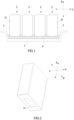
FIG. 1 is a schematic view showing the structure of a battery box of the present invention. -
FIG. 2 is a schematic view showing a position of an opening of an insulating film and a battery ofFIG. 1 . -
FIG. 3 is a variation ofFIG. 2 . - Reference numerals in figures are represented as follows:
- 1 box body
- 2 battery
21 case - 3 insulating film
31 opening - 4 adhesive
- X transversal direction
- Y longitudinal direction
- Z up-down direction
- To make the object, technical solutions, and advantages of the present invention more apparent, hereinafter the present invention will be further described in detail in combination with the accompanying figures and the embodiments. It should be understood that the specific embodiments described herein are merely used to explain the present invention but are not intended to limit the present invention that is as set out in the appended claims.
- In the description of the present invention, unless otherwise specifically defined and limited, the term "plurality" is two or more. For the persons skilled in the art, the specific meanings of the abovementioned terms in the present invention can be understood according to the specific situation.
- In the description of the present invention, it should be understood that spatially relative terms, such as "above", "below" and the like, are described based on orientations illustrated in the figures, but are not intended to limit the embodiments of the present invention. Hereinafter the present application will be further described in detail in combination with the figures.
- Referring to
FIG. 1 , a vehicle according to the present invention comprises a battery box, and the battery box comprises abox body 1, a plurality ofbatteries 2, aninsulating film 3 and an adhesive 4. - The plurality of
batteries 2 are arranged side by side in a longitudinal direction Y and are accommodated in thebox body 1. Eachbattery 2 comprises acase 21, and thecase 21 comprises two side faces in a transversal direction X, two large faces in the longitudinal direction Y and one bottom face in an up-down direction Z. Thecase 21 may be made of a metal material. - A bonding binder is provided on one side of the
insulating film 3 facing thebattery 2, so as to make theinsulating film 3 cover and bond to an outside of thecase 21 of thebattery 2. Anopening 31 is provided on theinsulating film 3, so as to make a corresponding portion of thecase 21 expose to theinsulating film 3. Specifically, theopening 31 may penetrate a portion of theinsulating film 3 covering a bottom face of thecase 21 of thebattery 2 in the up-down direction Z (i.e., theopening 31 is positioned below the bottom face of the case 21), so as to make a part of the bottom face of thecase 21 expose to the insulating film 3 (as shown inFIG. 2 ). Alternatively, theopening 31 may also penetrate a portion of theinsulating film 3 covering the side face of thecase 21 of thebattery 2 in the transversal direction X (i.e., theopening 31 is positioned outside the side face of the case 21), so as to make a part of the side face of thecase 21 expose through the insulating film 3 (as shown inFIG. 3 ). - The
adhesive 4 is provided between thebattery 2 and thebox body 1 and is used to fix eachbattery 2 to thebox body 1. After the plurality ofbatteries 2 are placed in thebox body 1, a portion of the adhesive 4 is positioned between the insulatingfilm 3 and thebox body 1, and a portion of the adhesive 4 is positioned between thecase 21 of thebattery 2 and the box body 1 (i.e., theopening 31 is filled with the adhesive 4). Of course, a portion of the adhesive 4 may also be interposed between the twoadjacent batteries 2. - After the battery box is assembled, the
case 21 of eachbattery 2 is bonded to thebox body 1 by the adhesive 4, and the insulatingfilm 3 is also bonded to thebox body 1 by the adhesive 4, thereby fixing eachbattery 2 in thebox body 1. - In the battery box of the present invention, an area of the
opening 31 of the insulatingfilm 3 is A 1, a total area of a surface of thecase 21 corresponding to theopening 31 is A, a thickness of the adhesive 4 is L 1, a volume resistivity of the adhesive 4 is ρ 1 , a thickness of the insulatingfilm 3 is L 2, a volume resistivity of the insulatingfilm 3 is ρ 2, and A 1, A , L 1 , ρ 1 , L 2 and ρ2 meet a following relationship:
- Because the insulating
film 3 is provided with theopening 31, a portion of the adhesive 4 bonds thecase 21 of thebattery 2 to thebox body 1 at theopening 31, a portion of the adhesive 4 bonds the insulatingfilm 3 to thebox body 1 at the outside of theopening 31, it ensures the bonding strength between thebattery 2 and thebox body 1. Meanwhile, because A, L 1, ρ 1 , L 2, ρ 2 and the area A 1 of theopening 31 of the insulatingfilm 3 meet the above relationship, it makes a covering area of the insulatingfilm 3 on thebattery 2 meet the requirement of the insulating strength (that is, the insulation failure of the inside of the battery box does not occur), thereby ensuring the safety performance of the battery box. - For the relationship (1), let


- The bonding strength of the
case 21 of thebattery 2 bonded to thebox body 1 by the adhesive 4 is related to an amount of the adhesive 4, and the amount of the adhesive 4 is related to the area A 1 of theopening 31 of the insulatingfilm 3, thus in order to ensure the requirement of the bonding strength of the battery box, preferably, A 1 and A need to meet the relationship: A 1 / A > 50%. - Meanwhile, because of the structure of the
battery 2 itself (i.e., rounded corners are formed at the four corners of the bottom of the battery 2), when the area A 1 of theopening 31 of the insulatingfilm 3 is too large, the risk of insulation failure between the rounded corners of the twoadjacent batteries 2 is increased. Therefore, in order to reduce the risk of insulation failure of thebattery 2, preferably, A 1 and A need to meet the relationship: A 1 / A ≤ 70% . - Because a high polymer material such as polypropylene (abbreviated as PP), polycarbonate (abbreviated as PC) or polyethylene terephthalate (abbreviated as PET) has larger volume resistivity (approximate 1014 Ω·cm) and good insulation performance, the insulating
film 3 can be made of one of the above high polymer materials, and at this time 0.1×10¹⁴Ω·cm ≤ ρ 2 ≤ 2×10¹⁴Ω·cm. - It should be noted that, the larger the thickness L 1 of the adhesive 4 is, it is more favorable to the bonding strength of the battery box, but when L 1 is too large, the insulation strength of the battery box is weakened in some extent. Therefore, in order to ensure the bonding strength and the insulating strength of the battery box at the same time, preferably, 0< L 1 ≤ 2mm.
- Because the insulating
film 3 covers the outside of thecase 21 of thebattery 2, and when the thickness L 2 of the insulatingfilm 3 is too large, the assembled size of thebattery 2 will be increased, it is beneficial to improve the energy density of the battery box; and when the thickness L 2 of the insulatingfilm 3 is too small, the bonding strength of the battery box can not be guaranteed. Therefore, preferably, 0 < L 2 ≤ 0.15mm. - In order to ensure the bonding strength between the adhesive 4 and the
case 21 of thebattery 2 and the bonding strength between the adhesive 4 and the insulatingfilm 3, in one embodiment, the material of the adhesive 4 may be a one-component polyurethane or a two-component polyurethane. A volume resistivity of the polyurethane in the initial state is 1010 Ω · cm, and the volume resistivity of the polyurethane will be increased over time (specifically, as shown in the flowing Table S-1, the unit is Ω·cm ) during use, until the polyurethane reaches a fully cured state (at this time, the volume resistivity of the polyurethane is 1012Ω·cm).Table S-1 30min 1h 6h 1day 5day 7day 1 4.31361E+10 8.11E+11 1.37028E+12 2.11023E+12 7.3858E+12 1.91839E+12 2 4.54362E+10 5.07E+11 8.57464E+11 1.32049E+12 4.62173E+12 1.20045E+12 3 2.04057E+10 4.88E+11 8.24205E+11 1.26928E+12 4.44246E+ 12 1.15389E+12 4 7.670895E+10 8.90E+11 1.50425E+12 2.31655E+12 8.10791E+12 2.10595E+12 5 5.24595E+10 4.37E+11 7.3877E+11 1.13771E+12 3.98197E+12 1.03428E+12 - For the adhesive 4 made of the one-component polyurethane, the bonding strength can be achieved by moisture curing or heat curing. For the adhesive 4 made of the two-component polyurethane, the bonding strength can be achieved by chemical bond and intermolecular force, and the bonding principle of the two-component polyurethane is specifically described below.
- The two-component polyurethane includes a component containing the -NCO group (such as single-isocyanate or multi-isocyanate) and a polyol-component containing the -OH group, and the component containing the -NCO group and the polyol-component containing the -OH group form the two-component polyurethane under a catalyst. The curing manner of the two-component polyurethane is as follows:
OCN-R-NCO + HO-R'-OH → OCN-R-NH-COOR'-OH
- The intermolecular force of the two-component polyurethane refers to a van der waals force between molecules, a hydrogen bond formed between a substrate (the substrate comprises the
case 21 of thebattery 2 and the insulating film 3) and the cured -NH- group, or a hydrogen bond formed between the substrate and the cured -OH group. The chemical bond refers to a covalent bond formed among the OCN-R-NCO not cured into the crosslinked network, a trace water on the surface of the substrate and the metal oxide. Moreover, in achieving the bonding strength of the adhesive 4, the intermolecular force of the two-component polyurethane plays a major role, and the chemical bond plays an auxiliary role. - In addition, it should be noted that, in the preparing process of the two-component polyurethane, the following two aspects should be noted: (1) because a part of -NCO can be consumed when it reacts with water and produces an urea group, the content of -NCO should be higher than the content of -OH; (2) although the higher the content of -NCO is , the more intermetallic covalents are formed, the better the bonding strength is, however when the content of -NCO is too high, the adhesive may be excessively hardened and become brittle, or even the state the colloid is not cured occurs. Therefore, a molar ratio between -NCO and -OH needs to be maintained within a certain range in the ratio preparing of the two-component polyurethane.
- In order to ensure the bonding strength between the adhesive 4 and the
case 21 of thebattery 2 and the bonding strength between the adhesive 4 and the insulatingfilm 3, in another embodiment, the material of the adhesive 4 may be a one-component epoxy resin or a two-component epoxy resin. A volume resistivity of the epoxy resin in the initial state is 108Ω· cm, and the volume resistivity of the epoxy resin will be increased over time (specifically, as shown in the flowing Table S-2, the unit is Ω·cm ) during use, until the epoxy resin reaches a fully cured state (at this time, the volume resistivity of the epoxy resin is 1013Ω·cm).Table S-2 30min 1h 6h 1day 5day 7day 1 3.507E+08 6.59E+09 5.69780E+10 2.69850E+12 3.96800E+13 4.51000E+13 2 3.694E+08 4.13E+09 5.11200E+10 3.33600E+12 4.69800E+13 6.98000E+13 3 1.659E+08 3.97E+09 1.36900E+10 3.14560E+12 2.33390E+13 7.98500E+13 4 6.2365E+08 7.24E+09 3.66600E+10 2.69700E+12 2.99800E+13 2.36900E+13 5 4.265E+08 3.55E+09 4.00100E+10 5.55600E+12 1.99800E+13 5.56500E+13 - For the adhesive 4 made of the one-component epoxy resin, the bonding strength can be achieved by moisture curing or heat curing. For the adhesive 4 made of the two-component epoxy resin, the bonding strength can be achieved by chemical bond and intermolecular force, and the bonding principle of the two-component epoxy resin is specifically described below.
- The two-component epoxy resin includes a component containing an epoxy group and a component containing the -OH group and the -NH2 group, and the component containing an epoxy group and the component containing the -OH group and the -NH2 group to form the two-component epoxy resin under a catalyst. The curing manner of the two-component epoxy resin is as follows:


- The intermolecular force of the two-component epoxy resin refers to a van der waals force formed between molecules, a hydrogen bond formed between the substrate and the epoxy group, a hydrogen bond formed between the substrate and the -OH group, a hydrogen bond formed between the substrate and the -NH2 group, or a hydrogen bond formed between the substrate and the -O-ether group. The chemical bond refers to a covalent bond formed by the component contained the -NH2 group, a trace water on the surface of the substrate and the metal oxide, and a covalent bond formed by the component containing the epoxy group, a trace water on the surface of the substrate and the metal oxide during the ring opening process.
- It should be noted that, because the molecules of the epoxy resin may be an additive reaction in the process of crosslinking, water and volatile product will not be generated, the overall curing shrinkage rate is low, the bulk strength is high, thereby achieving a strong bonding strength.
- In the present invention, in one test case, there were 20 test groups respectively formed by four adhesives 4 (defined as 1#, 2#, 3# and 4#, and 1#-4# adhesives were made of epoxy resin, the 1# adhesive was in the state that epoxy resin was at 30 min, 2 # adhesive was in the state that epoxy resin was at 1h, 3# adhesive was in the state that epoxy resin was at 1 day, 4# adhesive was in the state that epoxy resin was at 5 day) and the five different area ratios of the opening 31 of the insulating films 3 (L 1 = 0.5mm , L 2 = 0.11mm ), the corresponding value of F in each test group was calculated by using relationship (1), and the specific test results were as the following Table S-3:
Table S-3 test group the area ratio of the opening A 1 /A the value of F the test results 1# adhesive 1-1 50% 2000Ω failure 1-2 40% 2500Ω failure 1-3 30% 3300Ω failure 1-4 20% 5000Ω failure 1-5 10% 10000Ω failure 2# adhesive 2-1 50% 0.2MΩ failure 2-2 40% 0.25MΩ failure 2-3 30% 0.33MΩ failure 2-4 20% 0.5MΩ failure 2-5 10% 1MΩ failure 3# 3-1 50% 19.8MΩ pass adhesive 3-2 40% 24.6MΩ pass 3-3 30% 32.6MΩ pass 3-4 20% 48.1MΩ pass 3-5 10% 91.7MΩ pass 4# adhesive 4-1 50% 182MΩ pass 4-2 40% 217MΩ pass 4-3 30% 270MΩ pass 4-4 20% 357MΩ pass 4-5 10% 526MΩ pass - According to Table S-3, for the test groups formed by 1# adhesive and the test groups formed by 2# adhesive, the values of F calculated by using relationship (1) were all smaller than 10M Ω , and the test groups had failed the insulation test; for the test groups formed by 3# adhesive and the test groups formed by 4# adhesive, the values of F calculated by using relationship (1) were all greater than 10M Ω , and the test groups had passed the insulation test.
- In the present invention, in another test case, there were twenty test groups respectively formed by four adhesives 4 (defined as 5#, 6#, 7# and 8#, and the adhesives 5#-8# were made of polyurethane, 5# adhesive was in the state that polyurethane was at 30 min, 6# adhesive was in the state that polyurethane was at 1h, 7# adhesive was in the state that polyurethane was at 1 day, 8# adhesive was in the state that polyurethane was at 5 day) and the five different area ratios of the
opening 31 of the insulating films 3 ( L 1 = 0. 5 mm , L 2 = 0.11mm ), the corresponding value of F in each test group was calculated by using relationship (1), and the specific test results were as the following Table S-4.Table S-4 test group the area ratio of the opening A 1 / A the value of F the test results 5# adhesive 5-1 50% 0.182MΩ failure 5-2 40% 0.227MΩ failure 5-3 30% 0.3032MΩ failure 5-4 20% 0.454MΩ failure 5-5 10% 0.908MΩ failure 6# adhesive 6-1 50% 1.82MΩ failure 6-2 40% 2.27MΩ failure 6-3 30% 3.02MΩ failure 6-4 20% 4.53MΩ failure 6-5 10% 9.01MΩ failure 7# adhesive 7-1 50% 18.7MΩ pass 7-2 40% 22.4MΩ pass 7-3 30% 29.6MΩ pass 7-4 20% 43.7MΩ pass 7-5 10% 83.4MΩ pass 8# adhesive 8-1 50% 1.98GΩ pass 8-2 40% 4.25GΩ pass 8-3 30% 3.55GΩ pass 8-4 20% 6.99GΩ pass 8-5 10% 8.80GΩ pass - According to Table S-4, for the test groups formed by 5# adhesive n and the test groups formed by 6# adhesive, the values of F calculated by using relationship (1) were all smaller than 10M Ω , and the test groups had failed the insulation test; for the test groups formed by 7# adhesive and the test groups formed by 8# adhesive, the values of F calculated by using relationship (1) were all greater than 10M Ω , and the test groups had passed the insulation test.
- Therefore, as could be seen from the above test cases, the insulation strength of the battery box could be directly obtained by the relationship (1) in the subsequent structural design of the battery box, and there was no need for measurement by using an insulation withstanding voltage tester, thereby greatly reducing the cost and improving the production efficiency.
Claims (11)
- A battery box, comprising:a box body (1);a plurality of batteries (2) being arranged side by side in a longitudinal direction (Y) and accommodated in the box body (1), and each battery (2) comprising a case (21);an insulating film (3) covering and fixed to an outside of the case (21) of each battery (2), and an opening (31) being provided on the insulating film (3) to make a corresponding portion of the case (21) expose through the insulating film (3); andan adhesive (4), which is provided between the battery (2) and the box body (1) and fixes each battery (2) to the box body (1);characterized in thata portion of the adhesive (4) is positioned between the insulating film (3) and the box body (1), a portion of the adhesive (4) is positioned between the case (21) of the battery (2) and the box body (1) and the opening (31) is filled with the adhesive (4);an area of the opening (31) is A 1, a total area of a surface of the case (21) on a side corresponding to the opening (31) is A, a thickness of the portion of the adhesive (4) positioned between the case (21) of the battery (2) and the box body (1) is L 1, a volume resistivity of the adhesive (4) is ρ1, a thickness of the insulating film (3) is L2, a volume resistivity of the insulating film (3) is ρ 2, and A 1, A, L 1, ρ 1, L 2 and ρ 2 meet a following relationship:

- The battery box according to claim 1, wherein

- The battery box according to claim 1, wherein A 1 and A need to meet the relationship: A 1 / A > 50%.
- The battery box according to claim 1, wherein
the insulating film (3) is made of polypropylene, polycarbonate or polyethylene terephthalate, and 0.1×10¹⁴Ω · cm ≤ ρ 2 ≤ 2×10¹⁴Ω· cm . - The battery box according to claim 1, wherein 0 < L 1 ≤ 2mm .
- The battery box according to claim 1, wherein 0 < L 2 ≤ 0.15mm.
- The battery box according to claim 1, wherein the material of the adhesive (4) is a one-component polyurethane or a two-component polyurethane.
- The battery box according to claim 1, wherein the material of the adhesive (4) is a one-component epoxy resin or a two-component epoxy resin.
- The battery box according to claim 1, whereinthe case (21) of each battery (2) comprises a bottom face;the opening (31) is positioned below the bottom face of the case (21) in an up-down direction (Z) and makes a part of the bottom face of the case (21) expose through the insulating film (3).
- The battery box according to claim 1, whereinthe case (21) of each battery (2) comprises a side face;the opening (31) is positioned outside the side face of the case (21) in a transversal direction (X) and makes a part of the side face of the case (21) expose through the insulating film (3).
- A vehicle, comprising the battery box according to any one of claims 1-10.
Applications Claiming Priority (1)
| Application Number | Priority Date | Filing Date | Title |
|---|---|---|---|
| CN201811630123.8A CN111384314B (en) | 2018-12-29 | 2018-12-29 | battery box |
Publications (3)
| Publication Number | Publication Date |
|---|---|
| EP3675217A1 EP3675217A1 (en) | 2020-07-01 |
| EP3675217C0 EP3675217C0 (en) | 2025-06-18 |
| EP3675217B1 true EP3675217B1 (en) | 2025-06-18 |
Family
ID=68501349
Family Applications (1)
| Application Number | Title | Priority Date | Filing Date |
|---|---|---|---|
| EP19207854.1A Active EP3675217B1 (en) | 2018-12-29 | 2019-11-08 | Battery box and vehicle |
Country Status (7)
| Country | Link |
|---|---|
| US (1) | US11283130B2 (en) |
| EP (1) | EP3675217B1 (en) |
| JP (1) | JP6892908B2 (en) |
| CN (1) | CN111384314B (en) |
| ES (1) | ES3040416T3 (en) |
| HU (1) | HUE072814T2 (en) |
| WO (1) | WO2020135028A1 (en) |
Families Citing this family (22)
| Publication number | Priority date | Publication date | Assignee | Title |
|---|---|---|---|---|
| US12506215B2 (en) | 2022-03-23 | 2025-12-23 | Ford Global Technologies, Llc | Enclosure cover attachment configurations for traction battery packs with cell-to-pack battery systems |
| US12567642B2 (en) | 2022-03-23 | 2026-03-03 | Ford Global Technologies, Llc | Shim systems for traction battery packs |
| US12424695B2 (en) | 2022-03-23 | 2025-09-23 | Ford Global Technologies, Llc | Retention assemblies for traction battery packs with cell-to-pack battery systems |
| US12230826B2 (en) | 2022-03-23 | 2025-02-18 | Ford Global Technologies, Llc | Methods for assembling traction battery packs |
| US12374750B2 (en) | 2022-03-23 | 2025-07-29 | Ford Global Technologies, Llc | Traction battery pack assembling method |
| US12525637B2 (en) | 2022-03-23 | 2026-01-13 | Ford Global Technologies, Llc | Traction battery pack assembling method |
| US12603373B2 (en) | 2022-03-23 | 2026-04-14 | Ford Global Technologies, Llc | Traction battery pack assembling method |
| US12479327B2 (en) | 2022-03-23 | 2025-11-25 | Ford Global Technologies, Llc | Traction battery pack cell stack removal method and battery pack assembly |
| US12275298B2 (en) | 2022-03-23 | 2025-04-15 | Ford Global Technologies, Llc | Traction battery packs with cell-to-pack battery systems housed within irregularly shaped enclosures |
| CN114976330B (en) * | 2022-06-20 | 2024-10-22 | 中创新航技术研究院(江苏)有限公司 | A method and device for determining the withstand voltage value of a battery device and its insulating film |
| CN114937837B (en) * | 2022-07-20 | 2023-03-14 | 中创新航科技股份有限公司 | Battery, battery pack, and insulation structure processing system and method |
| CN116169419A (en) * | 2023-02-22 | 2023-05-26 | 四川国创成电池材料有限公司 | A battery packaging structure and packaging method thereof |
| WO2024207167A1 (en) * | 2023-04-04 | 2024-10-10 | 宁德时代新能源科技股份有限公司 | Battery pack, assembling method and disassembling method therefor, and electrical apparatus |
| WO2024243913A1 (en) * | 2023-05-31 | 2024-12-05 | 深圳海辰储能控制技术有限公司 | Energy storage battery, energy storage device, and electric apparatus |
| CN116666823A (en) * | 2023-06-26 | 2023-08-29 | 欣旺达动力科技股份有限公司 | Battery pack and electrical equipment |
| CN116742192A (en) * | 2023-06-26 | 2023-09-12 | 欣旺达动力科技股份有限公司 | Battery packs and electrical equipment |
| CN117977130B (en) * | 2024-03-29 | 2024-07-05 | 蜂巢能源科技股份有限公司 | Battery Cells and Battery Packs |
| CN223023462U (en) * | 2024-08-16 | 2025-06-24 | 惠州亿纬锂能股份有限公司 | Single battery and battery pack |
| CN118693477A (en) * | 2024-08-23 | 2024-09-24 | 中创新航科技集团股份有限公司 | Battery pack and power device |
| CN119601857B (en) * | 2024-12-10 | 2025-11-11 | 东风汽车有限公司东风日产乘用车公司 | Battery pack |
| CN120581809A (en) * | 2025-04-30 | 2025-09-02 | 中创新航科技集团股份有限公司 | battery pack |
| CN120581811A (en) * | 2025-04-30 | 2025-09-02 | 中创新航科技集团股份有限公司 | battery pack |
Citations (6)
| Publication number | Priority date | Publication date | Assignee | Title |
|---|---|---|---|---|
| EP1898227A1 (en) | 2006-09-06 | 2008-03-12 | Hitachi Vehicle Energy, Ltd. | Assembled battery total voltage detection and leak detection apparatus |
| EP2696389A1 (en) | 2011-06-02 | 2014-02-12 | Kabushiki Kaisha Toshiba | Secondary battery apparatus and method of manufacturing secondary battery apparatus |
| DE102015211656A1 (en) | 2014-12-10 | 2016-06-16 | Robert Bosch Gmbh | Battery cell with electrically insulating foil with contouring |
| US20170125756A1 (en) | 2014-06-20 | 2017-05-04 | David Nietling | Battery Module with Cell Fixation |
| CN206322806U (en) | 2017-01-04 | 2017-07-11 | 东莞塔菲尔新能源科技有限公司 | Housing of power cell capsule structure |
| US20180212222A1 (en) | 2017-01-20 | 2018-07-26 | Tesla Motors, Inc. | Energy storage system |
Family Cites Families (23)
| Publication number | Priority date | Publication date | Assignee | Title |
|---|---|---|---|---|
| US5187031A (en) * | 1991-08-07 | 1993-02-16 | Globe-Union Inc. | Anti-vibration plaque for a battery |
| JP4254998B2 (en) * | 2002-12-11 | 2009-04-15 | 日立マクセル株式会社 | Circuit integrated battery |
| CN1745438A (en) * | 2003-01-04 | 2006-03-08 | 3M创新有限公司 | A vehicle battery pack insulator |
| US20090014353A1 (en) * | 2007-07-09 | 2009-01-15 | Lewis Jr John Calvin | Battery box in a box packaging |
| US8216502B2 (en) | 2008-12-02 | 2012-07-10 | Tesla Motors, Inc. | Method for the external application of battery pack encapsulant |
| WO2012117681A1 (en) * | 2011-02-28 | 2012-09-07 | 三洋電機株式会社 | Battery module and method for manufacturing battery module |
| JP2013125617A (en) * | 2011-12-13 | 2013-06-24 | Sanyo Electric Co Ltd | Power supply device and vehicle having the same, and power storage device |
| DE102013204670B3 (en) * | 2013-03-18 | 2014-05-15 | Magna Steyr Battery Systems Gmbh & Co Og | Battery system used as energy storage for drive of e.g. electric vehicle, has electrically insulating adhesive portion with adhesive bead that is arranged between uncoated portion arranged close to cell and portion of uncoated portion |
| DE102015206182B4 (en) * | 2014-05-06 | 2025-02-06 | Robert Bosch Gmbh | Isolating adjacent lithium-ion batteries by completely overmolding/pouring the containers in one device |
| DE102014211821A1 (en) | 2014-06-20 | 2015-12-24 | Robert Bosch Gmbh | Battery cell, battery module containing them and process for their preparation |
| JP6260830B2 (en) * | 2014-10-28 | 2018-01-17 | 豊田合成株式会社 | Battery adhesive fixing structure |
| CN204271146U (en) * | 2014-12-22 | 2015-04-15 | 深圳市诺贝诺胶接技术有限公司 | A kind of electric automobile power battery module |
| US10403869B2 (en) * | 2015-04-13 | 2019-09-03 | Cps Technology Holdings, Llc | Adhesive tape for positioning battery cells in a battery module |
| JP6753045B2 (en) * | 2015-09-18 | 2020-09-09 | 株式会社Gsユアサ | Power storage device |
| CN106992320A (en) * | 2016-01-20 | 2017-07-28 | 松下能源(无锡)有限公司 | Battery with nonaqueous electrolyte |
| CN105762316A (en) | 2016-05-20 | 2016-07-13 | 宁德时代新能源科技股份有限公司 | Battery box |
| CN205900600U (en) * | 2016-07-19 | 2017-01-18 | 成都硅宝科技股份有限公司 | Safety battery group |
| CN107039613A (en) | 2017-02-23 | 2017-08-11 | 江苏银基烯碳能源科技有限公司 | A kind of battery bag |
| US10601090B2 (en) * | 2017-04-28 | 2020-03-24 | Nio Usa, Inc. | Using a spacer to block path of thermally conductive structural adhesive in lithium ion cells |
| CN207134401U (en) * | 2017-08-25 | 2018-03-23 | 宁德时代新能源科技股份有限公司 | Battery modules and battery bag |
| CN208111531U (en) * | 2018-04-17 | 2018-11-16 | 宁波吉利汽车研究开发有限公司 | A kind of battery case lower tray |
| CN108832053B (en) * | 2018-07-25 | 2024-03-19 | 江苏正力新能电池技术有限公司 | A battery module |
| CN208622878U (en) | 2018-08-31 | 2019-03-19 | 宁德时代新能源科技股份有限公司 | Secondary batteries and battery modules |
-
2018
- 2018-12-29 CN CN201811630123.8A patent/CN111384314B/en active Active
-
2019
- 2019-10-29 JP JP2019196220A patent/JP6892908B2/en active Active
- 2019-11-04 US US16/673,553 patent/US11283130B2/en active Active
- 2019-11-08 EP EP19207854.1A patent/EP3675217B1/en active Active
- 2019-11-08 HU HUE19207854A patent/HUE072814T2/en unknown
- 2019-11-08 ES ES19207854T patent/ES3040416T3/en active Active
- 2019-12-10 WO PCT/CN2019/124357 patent/WO2020135028A1/en not_active Ceased
Patent Citations (6)
| Publication number | Priority date | Publication date | Assignee | Title |
|---|---|---|---|---|
| EP1898227A1 (en) | 2006-09-06 | 2008-03-12 | Hitachi Vehicle Energy, Ltd. | Assembled battery total voltage detection and leak detection apparatus |
| EP2696389A1 (en) | 2011-06-02 | 2014-02-12 | Kabushiki Kaisha Toshiba | Secondary battery apparatus and method of manufacturing secondary battery apparatus |
| US20170125756A1 (en) | 2014-06-20 | 2017-05-04 | David Nietling | Battery Module with Cell Fixation |
| DE102015211656A1 (en) | 2014-12-10 | 2016-06-16 | Robert Bosch Gmbh | Battery cell with electrically insulating foil with contouring |
| CN206322806U (en) | 2017-01-04 | 2017-07-11 | 东莞塔菲尔新能源科技有限公司 | Housing of power cell capsule structure |
| US20180212222A1 (en) | 2017-01-20 | 2018-07-26 | Tesla Motors, Inc. | Energy storage system |
Non-Patent Citations (8)
| Title |
|---|
| ANONYMOUS: "BETAMATE 2091 Structural Adhesives Adhesive", DUPONT, 1 January 2026 (2026-01-01), XP093380224, Retrieved from the Internet <URL:https://dupontadh.materialdatacenter.com/gb/products/datasheet/SI/BETAMATE%E2%84%A2%202091> |
| ANONYMOUS: "Dielektrikum", SPECTRUM.DE, 1 January 2026 (2026-01-01), XP093380231, Retrieved from the Internet <URL:www.spectrum.de_Dielektrikum> |
| ANONYMOUS: "Electric vehicle conductive charging system - Part 1: General requirements", NATIONALE NORM DER VOLKSREPUBLIK CHINA; GB/T18487.1 - 2015, 28 December 2015 (2015-12-28), XP093380237 |
| ANONYMOUS: "Sikaflex -953 L30 - Produktdatenblatt", SIKA, 1 August 2025 (2025-08-01), XP093380217, Retrieved from the Internet <URL:https://industry.sika.com/dam/dms/deaddconst01/8/sikaflex-953-l30.pdf> |
| ANONYMOUS: "Strong-Bond 104 Electronic Industries Epoxy Adhesive, Special Formulation, 2 Part, Thixotropic", EPOXY INTERNATIONAL, 1 January 2026 (2026-01-01), XP093380227, Retrieved from the Internet <URL: https://epoxyinternational.com/strongbond-104-electronic-industries-epoxy-adhesive-special-formulation-2-part-thixotropic-adhesive > |
| ANONYMOUS: "Technical Data Sheet - 3M Scotch-Weld Multi-Material & Composite Urethane Adhesives 6300 Series", 3M, 1 July 2024 (2024-07-01), XP093380213 |
| ANONYMOUS: "Volume Resistivity", SPECIALCHEM.COM, 14 July 2025 (2025-07-14), XP093380205, Retrieved from the Internet <URL: https://www.specialchem.com/plastics/guide/volume-resistivity > |
| ETFE: "Electrical Properties of Plastic Materials", 1 January 2022 (2022-01-01), pages 1 - 4, XP055878940, Retrieved from the Internet <URL:https://www.professionalplastics.com/professionalplastics/ElectricalPropertiesofPlastics.pdf> |
Also Published As
| Publication number | Publication date |
|---|---|
| US20200212392A1 (en) | 2020-07-02 |
| CN111384314A (en) | 2020-07-07 |
| JP6892908B2 (en) | 2021-06-23 |
| ES3040416T3 (en) | 2025-10-30 |
| EP3675217C0 (en) | 2025-06-18 |
| JP2020109743A (en) | 2020-07-16 |
| WO2020135028A1 (en) | 2020-07-02 |
| EP3675217A1 (en) | 2020-07-01 |
| HUE072814T2 (en) | 2025-12-28 |
| CN111384314B (en) | 2021-01-19 |
| US11283130B2 (en) | 2022-03-22 |
Similar Documents
| Publication | Publication Date | Title |
|---|---|---|
| EP3675217A1 (en) | Battery box and vehicle | |
| US11128009B2 (en) | Battery box | |
| US8809102B2 (en) | Solar battery cell connection method and solar battery module | |
| JP5382256B1 (en) | Battery packaging material, battery container and battery | |
| EP3467895B1 (en) | Power storage device cladding | |
| EP2549549B1 (en) | Solar cell module | |
| CN102414829B (en) | Solar cell module | |
| TW201641646A (en) | Conductor connecting member, connection structure and solar battery module | |
| EP3633755A1 (en) | Exterior material for electricity storage device | |
| JP2017120790A (en) | Power storage device adhesive film for sealing metal terminal | |
| DE102018221631A1 (en) | Packaging material for energy storage device and energy storage device | |
| CN102938468A (en) | A fuel cell reinforced sealing method | |
| EP3920258A1 (en) | Outer package material for all-solid-state batteries, and all-solid-state battery using same | |
| CN221041374U (en) | Bonding structure of battery cell and battery pack box | |
| KR20140061964A (en) | Conductive adhesive, solar cell module and method of manufacturing solar cell module | |
| EP4280288A1 (en) | Photovoltaic sandwich panel, particularly pv vehicle cladding sandwich panel, and thermally insulated cargo box as well as vehicle comprising such panel and manufacturing method | |
| US20150188155A1 (en) | Membrane-electrode assembly (mea) for fuel cells | |
| CN205647395U (en) | Parting strip for solar module | |
| DE10102125A1 (en) | Thin electronic chip card used as a credit card or telephone card has a high strength film made from metal or fiber-reinforced plastic arranged between outer covering films and an energy storage device | |
| DE102017218923A1 (en) | Electrical bridging element, electrical energy storage and device | |
| CN112757723A (en) | Aluminum-plastic composite plate and preparation method and application thereof | |
| EP2600417A1 (en) | Solar battery module and method for producing same | |
| JP3419617B2 (en) | Solar cell module, manufacturing method and mounting method of the solar cell module | |
| EP1489675A3 (en) | Bonding electrochemical cell components | |
| DE102024114909A1 (en) | METHOD FOR MANUFACTURING A BATTERY OR BATTERY MODULE, BATTERY OR BATTERY MODULE AND MOTOR VEHICLE WITH THE BATTERY OR BATTERY MODULE |
Legal Events
| Date | Code | Title | Description |
|---|---|---|---|
| PUAI | Public reference made under article 153(3) epc to a published international application that has entered the european phase |
Free format text: ORIGINAL CODE: 0009012 |
|
| STAA | Information on the status of an ep patent application or granted ep patent |
Free format text: STATUS: REQUEST FOR EXAMINATION WAS MADE |
|
| 17P | Request for examination filed |
Effective date: 20191108 |
|
| AK | Designated contracting states |
Kind code of ref document: A1 Designated state(s): AL AT BE BG CH CY CZ DE DK EE ES FI FR GB GR HR HU IE IS IT LI LT LU LV MC MK MT NL NO PL PT RO RS SE SI SK SM TR |
|
| AX | Request for extension of the european patent |
Extension state: BA ME |
|
| REG | Reference to a national code |
Ref legal event code: R079 Free format text: PREVIOUS MAIN CLASS: H01M0002100000 Ipc: H01M0050121000 Ref country code: DE Ref document number: 602019071189 Country of ref document: DE |
|
| GRAP | Despatch of communication of intention to grant a patent |
Free format text: ORIGINAL CODE: EPIDOSNIGR1 |
|
| STAA | Information on the status of an ep patent application or granted ep patent |
Free format text: STATUS: GRANT OF PATENT IS INTENDED |
|
| RIC1 | Information provided on ipc code assigned before grant |
Ipc: H01M 50/119 20210101ALN20240711BHEP Ipc: H01M 50/209 20210101ALI20240711BHEP Ipc: H01M 50/133 20210101ALI20240711BHEP Ipc: H01M 50/131 20210101ALI20240711BHEP Ipc: B60L 50/64 20190101ALI20240711BHEP Ipc: H01M 50/124 20210101ALI20240711BHEP Ipc: H01M 50/121 20210101AFI20240711BHEP |
|
| TPAC | Observations filed by third parties |
Free format text: ORIGINAL CODE: EPIDOSNTIPA |
|
| INTG | Intention to grant announced |
Effective date: 20240807 |
|
| GRAJ | Information related to disapproval of communication of intention to grant by the applicant or resumption of examination proceedings by the epo deleted |
Free format text: ORIGINAL CODE: EPIDOSDIGR1 |
|
| STAA | Information on the status of an ep patent application or granted ep patent |
Free format text: STATUS: REQUEST FOR EXAMINATION WAS MADE |
|
| STAA | Information on the status of an ep patent application or granted ep patent |
Free format text: STATUS: EXAMINATION IS IN PROGRESS |
|
| RAP1 | Party data changed (applicant data changed or rights of an application transferred) |
Owner name: CONTEMPORARY AMPEREX TECHNOLOGY(HONG KONG) LIMITED |
|
| 17Q | First examination report despatched |
Effective date: 20240930 |
|
| INTC | Intention to grant announced (deleted) | ||
| GRAP | Despatch of communication of intention to grant a patent |
Free format text: ORIGINAL CODE: EPIDOSNIGR1 |
|
| STAA | Information on the status of an ep patent application or granted ep patent |
Free format text: STATUS: GRANT OF PATENT IS INTENDED |
|
| RIC1 | Information provided on ipc code assigned before grant |
Ipc: H01M 50/119 20210101ALN20250312BHEP Ipc: H01M 50/209 20210101ALI20250312BHEP Ipc: H01M 50/133 20210101ALI20250312BHEP Ipc: H01M 50/131 20210101ALI20250312BHEP Ipc: B60L 50/64 20190101ALI20250312BHEP Ipc: H01M 50/124 20210101ALI20250312BHEP Ipc: H01M 50/121 20210101AFI20250312BHEP |
|
| INTG | Intention to grant announced |
Effective date: 20250321 |
|
| GRAS | Grant fee paid |
Free format text: ORIGINAL CODE: EPIDOSNIGR3 |
|
| GRAA | (expected) grant |
Free format text: ORIGINAL CODE: 0009210 |
|
| STAA | Information on the status of an ep patent application or granted ep patent |
Free format text: STATUS: THE PATENT HAS BEEN GRANTED |
|
| AK | Designated contracting states |
Kind code of ref document: B1 Designated state(s): AL AT BE BG CH CY CZ DE DK EE ES FI FR GB GR HR HU IE IS IT LI LT LU LV MC MK MT NL NO PL PT RO RS SE SI SK SM TR |
|
| REG | Reference to a national code |
Ref country code: GB Ref legal event code: FG4D |
|
| REG | Reference to a national code |
Ref country code: CH Ref legal event code: EP |
|
| REG | Reference to a national code |
Ref country code: DE Ref legal event code: R096 Ref document number: 602019071189 Country of ref document: DE |
|
| REG | Reference to a national code |
Ref country code: CH Ref legal event code: EP |
|
| REG | Reference to a national code |
Ref country code: IE Ref legal event code: FG4D |
|
| U01 | Request for unitary effect filed |
Effective date: 20250710 |
|
| U07 | Unitary effect registered |
Designated state(s): AT BE BG DE DK EE FI FR IT LT LU LV MT NL PT RO SE SI Effective date: 20250716 |
|
| PG25 | Lapsed in a contracting state [announced via postgrant information from national office to epo] |
Ref country code: GR Free format text: LAPSE BECAUSE OF FAILURE TO SUBMIT A TRANSLATION OF THE DESCRIPTION OR TO PAY THE FEE WITHIN THE PRESCRIBED TIME-LIMIT Effective date: 20250919 Ref country code: NO Free format text: LAPSE BECAUSE OF FAILURE TO SUBMIT A TRANSLATION OF THE DESCRIPTION OR TO PAY THE FEE WITHIN THE PRESCRIBED TIME-LIMIT Effective date: 20250918 |
|
| PG25 | Lapsed in a contracting state [announced via postgrant information from national office to epo] |
Ref country code: HR Free format text: LAPSE BECAUSE OF FAILURE TO SUBMIT A TRANSLATION OF THE DESCRIPTION OR TO PAY THE FEE WITHIN THE PRESCRIBED TIME-LIMIT Effective date: 20250618 |
|
| PG25 | Lapsed in a contracting state [announced via postgrant information from national office to epo] |
Ref country code: RS Free format text: LAPSE BECAUSE OF FAILURE TO SUBMIT A TRANSLATION OF THE DESCRIPTION OR TO PAY THE FEE WITHIN THE PRESCRIBED TIME-LIMIT Effective date: 20250918 |
|
| REG | Reference to a national code |
Ref country code: ES Ref legal event code: FG2A Ref document number: 3040416 Country of ref document: ES Kind code of ref document: T3 Effective date: 20251030 |
|
| PGFP | Annual fee paid to national office [announced via postgrant information from national office to epo] |
Ref country code: HU Payment date: 20251107 Year of fee payment: 7 |
|
| REG | Reference to a national code |
Ref country code: HU Ref legal event code: AG4A Ref document number: E072814 Country of ref document: HU |
|
| U20 | Renewal fee for the european patent with unitary effect paid |
Year of fee payment: 7 Effective date: 20251127 |
|
| PG25 | Lapsed in a contracting state [announced via postgrant information from national office to epo] |
Ref country code: IS Free format text: LAPSE BECAUSE OF FAILURE TO SUBMIT A TRANSLATION OF THE DESCRIPTION OR TO PAY THE FEE WITHIN THE PRESCRIBED TIME-LIMIT Effective date: 20251018 |
|
| PGFP | Annual fee paid to national office [announced via postgrant information from national office to epo] |
Ref country code: GB Payment date: 20251126 Year of fee payment: 7 |
|
| PG25 | Lapsed in a contracting state [announced via postgrant information from national office to epo] |
Ref country code: SM Free format text: LAPSE BECAUSE OF FAILURE TO SUBMIT A TRANSLATION OF THE DESCRIPTION OR TO PAY THE FEE WITHIN THE PRESCRIBED TIME-LIMIT Effective date: 20250618 |
|
| PG25 | Lapsed in a contracting state [announced via postgrant information from national office to epo] |
Ref country code: CZ Free format text: LAPSE BECAUSE OF FAILURE TO SUBMIT A TRANSLATION OF THE DESCRIPTION OR TO PAY THE FEE WITHIN THE PRESCRIBED TIME-LIMIT Effective date: 20250618 |
|
| PG25 | Lapsed in a contracting state [announced via postgrant information from national office to epo] |
Ref country code: PL Free format text: LAPSE BECAUSE OF FAILURE TO SUBMIT A TRANSLATION OF THE DESCRIPTION OR TO PAY THE FEE WITHIN THE PRESCRIBED TIME-LIMIT Effective date: 20250618 |
|
| PG25 | Lapsed in a contracting state [announced via postgrant information from national office to epo] |
Ref country code: SK Free format text: LAPSE BECAUSE OF FAILURE TO SUBMIT A TRANSLATION OF THE DESCRIPTION OR TO PAY THE FEE WITHIN THE PRESCRIBED TIME-LIMIT Effective date: 20250618 |
|
| PGFP | Annual fee paid to national office [announced via postgrant information from national office to epo] |
Ref country code: ES Payment date: 20251202 Year of fee payment: 7 |
|
| PLBI | Opposition filed |
Free format text: ORIGINAL CODE: 0009260 |
|
| REG | Reference to a national code |
Ref country code: CH Ref legal event code: L11 Free format text: ST27 STATUS EVENT CODE: U-0-0-L10-L11 (AS PROVIDED BY THE NATIONAL OFFICE) Effective date: 20260325 |
|
| PLAB | Opposition data, opponent's data or that of the opponent's representative modified |
Free format text: ORIGINAL CODE: 0009299OPPO |
|
| REG | Reference to a national code |
Ref country code: CH Ref legal event code: L10 Free format text: ST27 STATUS EVENT CODE: U-0-0-L10-L00 (AS PROVIDED BY THE NATIONAL OFFICE) Effective date: 20260402 |
|
| 26 | Opposition filed |
Opponent name: VOLKSWAGEN AG Effective date: 20260318 |
|
| R26 | Opposition filed (corrected) |
Opponent name: VOLKSWAGEN AG Effective date: 20260318 |