EP3674794B1 - Support d'instrument, plate-forme mobile comprenant un tel support d'instrument et utilisation d'un tel support d'instrument - Google Patents
Support d'instrument, plate-forme mobile comprenant un tel support d'instrument et utilisation d'un tel support d'instrument Download PDFInfo
- Publication number
- EP3674794B1 EP3674794B1 EP18445001.3A EP18445001A EP3674794B1 EP 3674794 B1 EP3674794 B1 EP 3674794B1 EP 18445001 A EP18445001 A EP 18445001A EP 3674794 B1 EP3674794 B1 EP 3674794B1
- Authority
- EP
- European Patent Office
- Prior art keywords
- instrument
- mount
- base part
- lever
- base
- Prior art date
- Legal status (The legal status is an assumption and is not a legal conclusion. Google has not performed a legal analysis and makes no representation as to the accuracy of the status listed.)
- Active
Links
Images


Classifications
-
- B—PERFORMING OPERATIONS; TRANSPORTING
- B64—AIRCRAFT; AVIATION; COSMONAUTICS
- B64D—EQUIPMENT FOR FITTING IN OR TO AIRCRAFT; FLIGHT SUITS; PARACHUTES; ARRANGEMENT OR MOUNTING OF POWER PLANTS OR PROPULSION TRANSMISSIONS IN AIRCRAFT
- B64D47/00—Equipment not otherwise provided for
- B64D47/08—Arrangements of cameras
-
- B—PERFORMING OPERATIONS; TRANSPORTING
- B64—AIRCRAFT; AVIATION; COSMONAUTICS
- B64U—UNMANNED AERIAL VEHICLES [UAV]; EQUIPMENT THEREFOR
- B64U20/00—Constructional aspects of UAVs
- B64U20/80—Arrangement of on-board electronics, e.g. avionics systems or wiring
- B64U20/87—Mounting of imaging devices, e.g. mounting of gimbals
-
- F—MECHANICAL ENGINEERING; LIGHTING; HEATING; WEAPONS; BLASTING
- F16—ENGINEERING ELEMENTS AND UNITS; GENERAL MEASURES FOR PRODUCING AND MAINTAINING EFFECTIVE FUNCTIONING OF MACHINES OR INSTALLATIONS; THERMAL INSULATION IN GENERAL
- F16F—SPRINGS; SHOCK-ABSORBERS; MEANS FOR DAMPING VIBRATION
- F16F3/00—Spring units consisting of several springs, e.g. for obtaining a desired spring characteristic
- F16F3/02—Spring units consisting of several springs, e.g. for obtaining a desired spring characteristic with springs made of steel or of other material having low internal friction
-
- F—MECHANICAL ENGINEERING; LIGHTING; HEATING; WEAPONS; BLASTING
- F16—ENGINEERING ELEMENTS AND UNITS; GENERAL MEASURES FOR PRODUCING AND MAINTAINING EFFECTIVE FUNCTIONING OF MACHINES OR INSTALLATIONS; THERMAL INSULATION IN GENERAL
- F16F—SPRINGS; SHOCK-ABSORBERS; MEANS FOR DAMPING VIBRATION
- F16F3/00—Spring units consisting of several springs, e.g. for obtaining a desired spring characteristic
- F16F3/08—Spring units consisting of several springs, e.g. for obtaining a desired spring characteristic with springs made of a material having high internal friction, e.g. rubber
- F16F3/087—Units comprising several springs made of plastics or the like material
- F16F3/093—Units comprising several springs made of plastics or the like material the springs being of different materials, e.g. having different types of rubber
-
- F—MECHANICAL ENGINEERING; LIGHTING; HEATING; WEAPONS; BLASTING
- F16—ENGINEERING ELEMENTS AND UNITS; GENERAL MEASURES FOR PRODUCING AND MAINTAINING EFFECTIVE FUNCTIONING OF MACHINES OR INSTALLATIONS; THERMAL INSULATION IN GENERAL
- F16M—FRAMES, CASINGS OR BEDS OF ENGINES, MACHINES OR APPARATUS, NOT SPECIFIC TO ENGINES, MACHINES OR APPARATUS PROVIDED FOR ELSEWHERE; STANDS; SUPPORTS
- F16M13/00—Other supports for positioning apparatus or articles; Means for steadying hand-held apparatus or articles
- F16M13/02—Other supports for positioning apparatus or articles; Means for steadying hand-held apparatus or articles for supporting on, or attaching to, an object, e.g. tree, gate, window-frame, cycle
-
- G—PHYSICS
- G03—PHOTOGRAPHY; CINEMATOGRAPHY; ANALOGOUS TECHNIQUES USING WAVES OTHER THAN OPTICAL WAVES; ELECTROGRAPHY; HOLOGRAPHY
- G03B—APPARATUS OR ARRANGEMENTS FOR TAKING PHOTOGRAPHS OR FOR PROJECTING OR VIEWING THEM; APPARATUS OR ARRANGEMENTS EMPLOYING ANALOGOUS TECHNIQUES USING WAVES OTHER THAN OPTICAL WAVES; ACCESSORIES THEREFOR
- G03B17/00—Details of cameras or camera bodies; Accessories therefor
- G03B17/56—Accessories
- G03B17/561—Support related camera accessories
-
- F—MECHANICAL ENGINEERING; LIGHTING; HEATING; WEAPONS; BLASTING
- F16—ENGINEERING ELEMENTS AND UNITS; GENERAL MEASURES FOR PRODUCING AND MAINTAINING EFFECTIVE FUNCTIONING OF MACHINES OR INSTALLATIONS; THERMAL INSULATION IN GENERAL
- F16F—SPRINGS; SHOCK-ABSORBERS; MEANS FOR DAMPING VIBRATION
- F16F15/00—Suppression of vibrations in systems; Means or arrangements for avoiding or reducing out-of-balance forces, e.g. due to motion
- F16F15/02—Suppression of vibrations of non-rotating, e.g. reciprocating systems; Suppression of vibrations of rotating systems by use of members not moving with the rotating systems
- F16F15/04—Suppression of vibrations of non-rotating, e.g. reciprocating systems; Suppression of vibrations of rotating systems by use of members not moving with the rotating systems using elastic means
- F16F15/046—Suppression of vibrations of non-rotating, e.g. reciprocating systems; Suppression of vibrations of rotating systems by use of members not moving with the rotating systems using elastic means using combinations of springs of different kinds
-
- F—MECHANICAL ENGINEERING; LIGHTING; HEATING; WEAPONS; BLASTING
- F16—ENGINEERING ELEMENTS AND UNITS; GENERAL MEASURES FOR PRODUCING AND MAINTAINING EFFECTIVE FUNCTIONING OF MACHINES OR INSTALLATIONS; THERMAL INSULATION IN GENERAL
- F16F—SPRINGS; SHOCK-ABSORBERS; MEANS FOR DAMPING VIBRATION
- F16F15/00—Suppression of vibrations in systems; Means or arrangements for avoiding or reducing out-of-balance forces, e.g. due to motion
- F16F15/02—Suppression of vibrations of non-rotating, e.g. reciprocating systems; Suppression of vibrations of rotating systems by use of members not moving with the rotating systems
- F16F15/04—Suppression of vibrations of non-rotating, e.g. reciprocating systems; Suppression of vibrations of rotating systems by use of members not moving with the rotating systems using elastic means
- F16F15/08—Suppression of vibrations of non-rotating, e.g. reciprocating systems; Suppression of vibrations of rotating systems by use of members not moving with the rotating systems using elastic means with rubber springs ; with springs made of rubber and metal
- F16F15/085—Use of both rubber and metal springs
-
- F—MECHANICAL ENGINEERING; LIGHTING; HEATING; WEAPONS; BLASTING
- F16—ENGINEERING ELEMENTS AND UNITS; GENERAL MEASURES FOR PRODUCING AND MAINTAINING EFFECTIVE FUNCTIONING OF MACHINES OR INSTALLATIONS; THERMAL INSULATION IN GENERAL
- F16F—SPRINGS; SHOCK-ABSORBERS; MEANS FOR DAMPING VIBRATION
- F16F2228/00—Functional characteristics, e.g. variability, frequency-dependence
- F16F2228/001—Specific functional characteristics in numerical form or in the form of equations
- F16F2228/005—Material properties, e.g. moduli
- F16F2228/007—Material properties, e.g. moduli of solids, e.g. hardness
-
- F—MECHANICAL ENGINEERING; LIGHTING; HEATING; WEAPONS; BLASTING
- F16—ENGINEERING ELEMENTS AND UNITS; GENERAL MEASURES FOR PRODUCING AND MAINTAINING EFFECTIVE FUNCTIONING OF MACHINES OR INSTALLATIONS; THERMAL INSULATION IN GENERAL
- F16F—SPRINGS; SHOCK-ABSORBERS; MEANS FOR DAMPING VIBRATION
- F16F2238/00—Type of springs or dampers
- F16F2238/02—Springs
- F16F2238/026—Springs wound- or coil-like
Definitions
- the present invention relates to a mount for instruments, such as cameras, laser range finders, antennae, gas detectors, radars and other types of sensitive sensors. Furthermore, such sensors may be installed in a gimballed arrangement allowing the sensors to change pointing direction with respect to the mount.
- the mount finds particular application for mounting instruments on movable platforms, such as aerial vehicles, but also for mounting instruments on a movable or vibrating part of a fixed structure, such as on a weak mast or the like.
- mounts with arrangements for dampening the vibration movement can be used.
- mounts comprise a base part that is to be attached to a fuselage of the aerial vehicle and an instrument part to which the instrument is attached.
- a number of elastic elements e.g. springs are used between the two.
- the elastic elements between the two parts/interfaces need to also dissipate energy. Therefore, springs are normally complemented by damper elements of some sort.
- a problem with the mount as described above is that when the instrument is subjected to forces perpendicular to the instrument's direction of protrusion from the fuselage, e.g. as a consequence of wind forces or accelerations, the orientation of the instrument relative to the fuselage may change. That is, the instrument may tilt relative to the fuselage. This may cause the instrument to collide with adjacent structures or to provide incorrect data in those cases where the orientation of the instrument relative to the fuselage is critical.
- Another inherent problem with a mount such as described above is that vibrations in the horizontal direction may cause the instrument arrangement to enter into an uncontrolled pendelum motion, in particular in those cases when the center of gravity of the sensor arrangement is far away from the base part.
- a particular object is to provide a more robust mount, which is capable of counteracting instrument tilt.
- a mount for mounting an instrument to a movable platform.
- the mount comprises a base part, attachable to the platform, an instrument part, to which the instrument is attachable, and a spring and damper arrangement operable between the base part and the instrument part to allow the instrument part to move relative to the base part.
- the mount further comprises first and second lever sets, each lever set comprising at least two parallel and spaced apart levers, which are rigidly connected to each other and which are pivotably connected to one of the base part and the instrument part.
- the lever sets are pivotable about respective first and second geometric axes, which are non-parallel with each other.
- the lever sets are pivotable about a respective proximal portion of the lever.
- a distal portion of each of the levers is connected to the other one of the base part and the instrument part by a respective elongate flexible member presenting internal hysteresis.
- the base part is the part which is intended to be mounted to the structure that is to carry the mount.
- the instrument part is the part to which the instrument is to be mounted. Alternatively, the instrument part may be integrated with the instrument.
- flexible in the context of the flexible member, should be understood to imply that the member is sufficiently flexible to allow it to be deformed as disclosed herein by such forces as will be relevant in the respective application. It is understood that the amount of such forces will vary depending on the weight and size of the instrument that the mount is adapted to carry, as well as external forces generated by the platform or by the motion of the platform (e.g. acceleration and wind forces.
- the members will be more flexible, in the sense that they present lower (preferably much lower) bending stiffness, than the base part and the instrument part.
- the base part and the instrument part can thus be regarded as rigid in the present application, in the sense that their flexibility is negligible. Likewise, the fact that the levers are rigidly connected to each other means that any the flexibility of the lever set is negligible.
- the members may be elongated and have a substantially constant cross section over their respective length.
- the members may present a thickness of 1-7 mm, preferably 2-6 mm and a length of 20-80 mm, preferably 30-70 mm.
- a length to thickness ratio of each of the members may be in the range 3-80, preferably 4-70, 5-70, 10-40 or 15-30.
- the flexible members should present internal hysteresis such that their bending and return movements are dampened.
- each of the flexible members should present greater internal hysteresis than a solid metal rod having the same thickness.
- lever sets and flexible members connecting the instrument and the base part will readily allow linear relative movement of the base part and the instrument part in directions which are parallel to a main plane of the base member and in a direction perpendicular to the main plane of the base member.
- movements causing the relative orientations of the instrument part and the base part to change such as those incurred by a torque applied to the instrument part about an axis parallel with the main plane of the base member, will be counteracted.
- the mount will allow some relative movement between the base part and the instrument part, it will counteract movements that are particularly undesirable and it will provide dampening of vibrations.
- the flexible members may have a thickness of 1-7 mm, preferably 2-5 mm.
- the flexible members may have a length of 20-80 mm, preferably 30-70 mm.
- At least one of the flexible members may comprise at least one of a plurality of metal filaments, at least one rubber elastic polymer member and at least one reinforced polymer member.
- the member may be formed by a metal wire, a reinforced polymer member, such as a rod or tube, an elongated rubber member, such as a rod or tube, or a hybrid comprising one or more metal filaments, polymer/metal wires or filaments, tubes or rods.
- the axes may present a mutual angle between 45 and 135 degrees, preferably 45-75 degrees.
- the number of lever sets may be 2-6, preferably 3-5 or 3-4.
- the mount may further comprise at least one biasing member configured to bias the instrument part and the base part towards a predetermined mutual position.
- the predetermined mutual position may be determined based on the weight of the instrument that is to be carried by the mount, such that the mount, in an equilibrium/static will provide a predetermined relative position of the base part and the instrument part.
- the biasing member may be configured to bias the instrument part towards the base part.
- the mount may further comprise at least one position limiter arranged on one of the base part and the instrument part, wherein the other one of the base part and the instrument part is biased towards the position limiter.
- At least one of the levers may be connected to each other by an axle, which is pivotably connected to said one of the base part and the instrument part.
- At least one of the levers may be pivotably connected to a lever base by respective pin members.
- the lever set may be connected to said one of the base part and the instrument part by at least one set of crossed spring blades.
- the spring blades of a lever set may be arranged in an X-configuration, with the axis of the lever set substantially coinciding with the junction of the X configuration. However, a slight displacement of the position of the axis may take place.
- a movable platform comprising a platform body, an instrument, and an instrument mount as disclosed above, wherein the instrument is mounted to the platform body by means of the mount.
- the instrument may comprise at least one of gimbal, a camera, a laser range finder, an antenna, a gas detector and a radar transmitter/detector a camera.
- the movable platform may be an aerial vehicle.
- the movable platform may be a weak mast.
- a mount as disclosed above, for mounting an instrument to a movable platform.
- the instrument may comprise at least one of gimbal, a camera, a laser range finder, an antenna, a gas detector and a radar transm itter/detector.
- the platform may be an aerial vehicle.
- the platform may be a weak mast.
- an instrument mount 1 comprising a base part 11 and an instrument part 12.
- the parts 11, 12 are shown as essentially coaxially arranged annular parts with generally circular outlines.
- the parts may have respective central openings, which also may be generally circular.
- the base part 11 may have a substantially planar surface facing the structure carrying the mount. This planar surface defines a main plane of the base part. A direction perpendicular to the main plane is defined as an axial direction of the mount. Directions perpendicular to the axial direction are defined as radial directions.
- the base part 11 as well as the instrument part 12 may be produced from a lightweight metal or metal alloy, such as aluminum or titanium alloys, or from or glas or carbon reinforced plastics, or even thermoplastics of suitable quality and stiffness.
- a lightweight metal or metal alloy such as aluminum or titanium alloys, or from or glas or carbon reinforced plastics, or even thermoplastics of suitable quality and stiffness.
- Non-limiting example production methods include casting and various additive manufacturing techniques.
- the parts 11, 12 may present a generally L-shaped profile.
- the base part 11 may be designed with an upside-down L-profile, with a horizontal part 111 forming the planar surface and the vertical part 112 forming an outermost rim of the base part 11.
- the instrument part 12 may be formed with an L-shaped profile wherein the vertical part 122 forms an inwardly facing part of the annular frame and with the horizontal part 121 forming a downwardly facing surface.
- Both parts 11, 12 may be provided with a plurality of reinforcements 113, 114; 124, 125, 126, which may provide for attachments for the components that will be discussed below.
- one, or both, of the parts 11, 12 may be formed without any central opening.
- the mount as illustrated comprises three lever sets 13a, 13b, 13c, each lever set comprising a pair of effectively parallel levers 131.
- lever sets 13a, 13b, 13c are arranged on the base part 11. However, it is understood that lever sets 13a, 13b, 13c may instead be arranged on the instrument part 12.
- the lever sets 13a, 13b, 13c are pivotable about a respective geometric axis provided approximately at a proximal portion 131p of the respective lever 131.
- the proximal portion of the levers coincides with the geometric axis about which the levers are rotatable.
- the geometric axes are non-parallel with each other.
- the axes may be perpendicular.
- the axes may present mutual angles of about 60 degs.
- the axes may be arranged on the sides of a square.
- the axes may be arranged on the sides of an equilateral pentagon, etc.
- the levers 131 forming part of a lever set 13a, 13b, 13c are rigidly connected to each other, such that the levers' pivot positions, but for deflection of the connector member 132 connecting the levers, will always be the same.
- the connector member 132 connecting the levers should be designed so as not to deform at the loads for which the system is designed. That is, the amount of the deformation should be negligible for the forces that the connector member 132 will normally be subjected to.
- each lever 131 is connected to the instrument part 12 by a respective elongate flexible member 14 presenting internal hysteresis.
- Each of the flexible members 14 may be formed by a metal multifilament wire, by a flexible rod, or by a flexible tube.
- the flexible member 14 may be formed of a polymeric material, such as a rubber elastic material.
- composite materials are possible, such as fiber reinforced polymeric materials. Also composite members are plausible, i.e. wires containing a plurality of filaments made from different materials.
- the members 14 should be sufficiently flexible to allow elastic bending, such that the instrument part 12 may move in directions parallel to a plane of the base part 11.
- the members 14 should be sufficiently rigid to counteract tilting of the instrument part 12 relative to the base part.
- the members should be able to withstand a sufficiently high compressive force in the longitudinal direction.
- the members 14 should present internal hysteresis such that bending movements result in energy dissipation and thus are effectively dampened.
- stainless steel metal multifilament wires having a thickness of 2-4 mm have proven useful, at least for instruments in a mass range of 1-15 kg.
- each lever set 13, 13a, 13b, 13c the levers 131 are spaced from each other.
- the levers are spaced as far as possible from each other.
- a spacing of the levers may be on the order of 25-75 % of a greatest footprint dimension of the base member 11.
- the lever spacing may be on the order of 25-75 % of an outer diameter of such annulus.
- the levers may be spaced by some 50-200 mm, preferably 100-200 mm.
- the mount may further comprise one or more biasing springs 15 with the purpose of carrying the mass (gravitational forces) of the instrument at rest.
- biasing springs 15 may be arranged to bias the base part 11 and the instrument part 12 towards a predetermined relative position.
- the springs 15 may be formed by helical springs operating in tension mode.
- FIG. 2 there is illustrated an exploded view of the instrument mount 1 of fig. 1 .
- one of the lever sets 13a has been disconnected from a lever set base 133.
- two of the biasing springs 15 have been disconnected from the base and a third biasing spring 15 has been disconnected altogether.
- Five of the members 14 have been disconnected from their associated levers 131 with a sixth members 14 having been disconnected altogether.
- the members 14 can be connected to the instrument part 12 by means of clamps 123, with each clamp comprising a pair of clamping members and one or more screws or bolts to force the clamping members together.
- a groove may be provided for receiving the member 14.
- Other clamping arrangements may also be used as illustrated in Fig 15a-15b .
- Corresponding clamps 1314 may be provided at the distal portions 131d of the levers 131.
- the springs 15 may be attached to the parts 11, 12 by means of e.g. lugs or the like. Such lugs may be provided at reinforced portions 114, 124 of the respective part 11, 12.
- the lever set base 133 may comprise a base body 1331 and an axle 1332, which may be insertable in the base body 1331.
- the axle 1332 may be fixable relative to the base body 1331.
- the base body 1331 may, in turn, be connected to the base part 11, or to the instrument part 12, as the case may be.
- the lever base 133 may be connected to the associated part 11, 12, which in the illustrated example is the base part 11, at a reinforcement 113 provided in the part.
- reinforcement 113 may be provided by a portion of the base part 11 having greater material thickness.
- the reinforcement may be provided with holes or recesses, which may be threaded, to allow mounting of the lever set base 133 by means of e.g. screws or bolts.
- the lever set 13a, 13b, 13c is formed by a connector member 132, which connects a pair of lever forming members 1311.
- the lever forming members 1311 may comprise a respective recess 1312 for receiving a respective bearing 1313, by which the axle 1332 may be engaged.
- the recesses may be open towards a direction that is parallel, and preferably coaxial with an axis A, about which the lever set 13 is pivotable.
- clamps 1314 comprising at least one clamp member 13141, 134142 and at least one faster 13143 are provided and connected to distal portions 131d of the lever forming members 1311.
- the clamps 1314 may comprise a pair of clamp members 13141, 13142, each comprising a respective groove for receiving the members 14, a single clamp member may be sufficient, with the lever forming members providing the other clamp member.
- the clamps may be connected to the associated part 11, 12, which in the illustrated example is the instrument part 12, at reinforced portions 125 formed in the part 12.
- reinforced portions may be provided as portions of material thickness that is greater than surrounding portions.
- Such reinforced portions may be provided with holes or recesses, which may be threaded so as to facilitate mounting by means of threaded members, such as screws or bolts.
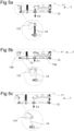
- Fig 5a schematically illustrates the mount in a non-loaded state, where both the base part 11 and the instrument part 12 are horizontally oriented.
- the biasing springs 15 are biasing the instrument part 12 towards the base part 11, so that the instrument part 12 is in its equilibrium position, i.e. a position where the instrument is mounted (thus exerting force F0 on the mount), but wherein both the platform and the instrument are stationary.
- the springs 15 are slightly extended and the levers 131 extend approximately horizontally and the members 14 are straight and vertical. It is noted that the springs 15 may be selected based on instrument mass, so that this equilibrium position (in which the load carried by the flexible members is negligable) will be achieved.
- Fig. 5b schematically illustrates the mount in a negatively axially loaded state, where a vertically upwardly acting force F1 is applied to the instrument part 12.
- the force can result from an inertial force provided by an instrument mounted to the instrument part 12, in connection with an acceleration of the platform or by vibrations.
- Fig. 5c schematically illustrates the mount in a positively axially loaded state, wherein a downwardly acting force F2 is applied to the instrument part 12. Again, this force can be due to vibrations and/or accelerations of the platform, as described previously.
- F2 downwardly acting force
- the springs 15 have been further extended and the levers 131 are now pointing slightly downwardly. The relative movement between the base part 11 and the instrument part 12 is limited by the members 14.
- the relative axial movement between the base part 11 and the instrument part 12 is a dampened movement.
- Fig 6a-6b and 7a-7b schematically illustrates the mount when subjected to a force F3 operating in the radial direction, i.e. perpendicular to the forces F1, F2 and thus horizontally as seen in the drawings.
- the instrument part 12 When the force F3 is applied to the instrument part 12, the instrument part 12, due to the flexibility of the members 14 and of the springs 15, will move horizontally, and in a direction parallel with a plane of the base member. That is, the constant length of the members causes the instrument part 12 to move as a parallelogram relative to the base part 11, thus limiting the motion of the instrument part with respect to the base part so that the two remain essentially parallel.
- the mount readily allows relative axial and radial movements between the instrument pat 12 and the base part 11, while at the same time effectively hindering/attenuating any pendulum movement.This is achieved without adding any damaging frictions such as that casued by ball joints in a conventional roll-stabilizing arrangement. Also, the flexible members are inherently tolerant against contamination and wear by selecting proper materials.
- a mount 1 to which an instrument in the form of a gimballed camera 2 (which may be capable of remote controlled motion in two or more directions) has been attached. Moreover, the mount has been provided with a mount shroud 16. Mounting of the instrument to the instrument part 12 of the mount may be improved by providing reinforces portions 126 in the instrument part 12. Such reinforced portions may be provided with holes or recesses, which may be threaded so as to facilitate mounting by means of threaded members, such as screws or bolts.
- a mount 1 which is mounted under a wing of an airplane and which carries an instrument 2 in the form of a gimballed camera.
- the mount and the instrument carried by the mount may be mounted on an underside of a fuselage of an airplane, a helicopter or a drone.
- the mount typically is mounted with the base part 11 attached to an underside of the vehicle or other structure carrying it, and that the instrument part 12 is typically suspended vertically below the base part 11.
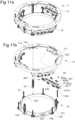
- FIG. 11a-11b there is illustrated another embodiment of an instrument mount, in which the rigid shafts are rotating by means of cross arranged spring blades.
- Figs 11a-11b correspond to figs 1-2 , and so identical items have been given the same reference numerals. Reference is made to figs 1-2 for description of such items.
- the lever set comprises a pair of levers 431 formed by a respective lever body 4311 and a respective connecting member 432, which rigidly connects the levers 431. Moreover, a lever base 433 is provided for connection to the base member 11, in a manner similar to the base 133 disclosed above. Similar to the first embodiment, the levers 431 may present a respective proximal end 431p and a respective distal end 431d.
- Each set of spring blades comprises at least two elongate spring blades, which are arranged in an X configuration, such that main planes of the spring blades intersect at an angles of 90 degs +/- 30 degs, preferably +/- 15 degs, +/- 5 degs or at right angles.
- the spring blades may, as illustrated in fig. 11b , each be formed by a single spring blade.
- the spring blades may be formed with recesses and/or holes so that the spring blades may laterally overlap each other.
- each spring blade may, as illustrated in fig. 12a , be formed by two or more separate and spaced apart spring blades.
- each set of spring blades may be formed by one central blade extending in a first plane and a pair of peripheral spring blades extending in a second plane, perpendicular to the first plane and on opposite lateral sides of the central spring blade.
- the spring blades may, as illustrated, be connected to the member 432 and to the lever base 433 by screws. Other attachments are possible, such as welding, riveting or snap arrangements.
- Figs 12a-12c correspond to figs 5a-5c , respectively.
- Figs 13a-13b and 14a-14b correspond to figs 6a-6b and 7a-7b , respectively, and show the behavior of the mount when the instrument part is subjected to a radial load.
- the function is the same as that of the first embodiment.
- FIG. 15a-15b there is illustrated another embodiment of an instrument mount, in which the rigid shafts are based on standard cylindrical rods.
- Figs 15a-15b correspond to figs 1-2 , and so identical items have been given the same reference numerals. Reference is made to figs 1-2 for description of such items.
- figs 15a-15b comprises a pair of lever bases 533 for attachment to the base member 11.
- the lever bases preset a respective recess, herein the form of a through hole 5331, in which a respective bearing 5313 is received.
- An axle 532 is received in the bearings 5313 and at spaced apart portions of the axle 532 levers 531 are attached.
- the levers 531 may be releasably attached, e.g. by means of screws 5311, as illustrated. Other attachment arrangements may be used, such as splines, etc.
- a clamp 5314 for connecting the flexible member 14 may be provided at the distal portion of the lever 531.
- the clamp may be activated by a nut 53141 and bolt 53142 arrangement, as illustrated.
- axial limiters 16 may be provided at an axially distal portion of the lever bases 533.
- the axial limiters may be provided with a softer material, e.g. to reduce impact, noise and/or wear.
- Axial limiters 16 may alternatively be provided as separate members extending axially from one of the base part 11 or the instrument part 12. Moreover, it is possible to provide the axial limiter on an axially distal portion of the lever bodies 131.
- lever set concepts disclosed herein may be used, for example one of each lever set concept, two of each lever set concept, etc.
- the flexible members 14 need to be selected and adapted for the load case of each specific application.
- the material or material combination pure material, alloys, composites, etc.
- member configuration number of filaments, filament materials, filament thicknesses, etc.
- length and thickness of the members may be selected so as to provide sufficient axial rigidity, bending stiffness and hysteresis of the members 14.
- the number of lever sets applied may be varied in order to fit different applications, and in particular different load cases.
- the biasing members 15 will need to be selected to fit each load case, so that a desired static position can be achieved.
Landscapes
- Engineering & Computer Science (AREA)
- General Engineering & Computer Science (AREA)
- Mechanical Engineering (AREA)
- Aviation & Aerospace Engineering (AREA)
- Physics & Mathematics (AREA)
- Microelectronics & Electronic Packaging (AREA)
- Remote Sensing (AREA)
- Acoustics & Sound (AREA)
- Chemical & Material Sciences (AREA)
- Combustion & Propulsion (AREA)
- General Physics & Mathematics (AREA)
- Vibration Prevention Devices (AREA)
- Accessories Of Cameras (AREA)
Claims (15)
- Monture (1) destinée au montage d'un instrument sur une plate-forme mobile, la monture comprenant :une partie de base (11), pouvant être fixée à la plate-forme,une partie d'instrument (12), à laquelle l'instrument peut être fixé,un dispositif de ressort et d'amortisseur (14, 15) pouvant fonctionner entre la partie de base (11) et la partie d'instrument (12) pour permettre à la partie d'instrument (12) de se déplacer par rapport à la partie de base (11), etun premier et un second jeu de leviers (13, 13a, 13b, 13c), chaque jeu de leviers comprenant au moins deux leviers parallèles et séparés (131), qui sont reliés de manière rigide l'un à l'autre et qui sont reliés de manière pivotante à l'une de la partie de base (11) et de la partie d'instrument (12),dans laquelle les jeux de leviers peuvent pivoter autour d'une partie proximale respective (131p) du levier (131),caractérisée en ce queles jeux de leviers (13, 13a, 13b, 13c) peuvent pivoter autour d'un premier et d'un second axes géométriques respectifs, qui ne sont pas parallèles entre eux, etqu'une partie distale (131d) de chacun des leviers (131) est reliée à l'autre partie de la base et à la partie d'instrument au moyen d'un élément flexible allongé respectif (14) présentant une hystérésis interne.
- Monture selon la revendication 1, dans laquelle les éléments flexibles ont une épaisseur comprise entre 1 et 7 mm, de préférence comprise entre 2 et 5 mm.
- Monture selon la revendication 1 ou la revendication 2, dans laquelle les éléments flexibles ont une longueur comprise entre 20 et 80 mm, de préférence comprise entre 30 et 70 mm.
- Monture selon l'une quelconque des revendications précédentes, dans laquelle au moins un des membres flexibles comprend au moins l'un parmi :une pluralité de filaments métalliques,au moins un élément polymère élastique en caoutchouc, etau moins un élément polymère renforcé.
- Monture selon l'une quelconque des revendications précédentes, dans laquelle les axes présentent un angle mutuel compris entre 45 et 135 degrés, de préférence compris entre 45 et 75 degrés.
- Monture selon l'une quelconque des revendications précédentes, dans laquelle le nombre de jeux de leviers est compris entre 2 et 6, de préférence compris entre 3 et 5 ou compris entre 3 et 4.
- Monture selon l'une quelconque des revendications précédentes, comprenant en outre au moins un élément de sollicitation (15) configuré pour solliciter la partie d'instrument et la partie de base vers une position mutuelle prédéterminée.
- Monture selon l'une quelconque des revendications précédentes, comprenant en outre au moins un limiteur de position (16) disposé sur l'une de la partie de base et de la partie d'instrument, dans laquelle l'autre partie de base et la partie d'instrument sont sollicitées vers le limiteur de position.
- Monture selon l'une quelconque des revendications précédentes, dans laquelle les leviers (531) sont reliés entre eux par un axe (532), lequel est relié de manière pivotante à ladite partie de base (11) et à la partie instrumentale (12).
- Monture selon l'une quelconque des revendications précédentes, dans laquelle les leviers (131) sont reliés de manière pivotante à une base de levier (133) par des éléments d'axe respectifs (1332).
- Monture selon l'une quelconque des revendications 1 à 8, dans laquelle le jeu de leviers est relié à ladite partie de base (11) et à la partie d'instrument (12) par au moins un jeu de lames de ressort croisées (435a, 435b).
- Plate-forme mobile, comprenant :un corps de plate-forme,un instrument, etune monture d'instrument selon l'une quelconque des revendications précédentes,dans laquelle l'instrument est monté sur le corps de plate-forme au moyen de la monture.
- Plate-forme mobile selon la revendication 12, dans laquelle l'instrument comprend au moins l'un des éléments suivants : un cardan, un appareil photo, un télémètre laser, une antenne, un détecteur de gaz et un émetteur/détecteur radar.
- Plate-forme mobile selon l'une quelconque des revendications 12 à 13, dans laquelle la plate-forme est un véhicule aérien ou un faible mât.
- Utilisation d'une monture selon l'une quelconque des revendications 1 à 11 permettant le montage d'un instrument sur une plate-forme mobile.
Priority Applications (8)
| Application Number | Priority Date | Filing Date | Title |
|---|---|---|---|
| EP18445001.3A EP3674794B1 (fr) | 2018-12-28 | 2018-12-28 | Support d'instrument, plate-forme mobile comprenant un tel support d'instrument et utilisation d'un tel support d'instrument |
| US17/418,504 US11781615B2 (en) | 2018-12-28 | 2019-12-20 | Instrument mount movable platform comprising such instrument mount and use of such instrument mount |
| KR1020217023451A KR20210107791A (ko) | 2018-12-28 | 2019-12-20 | 기구 마운트, 이러한 기구 마운트를 포함하는 이동식 플랫폼, 및 이러한 기구 마운트의 사용 |
| IL284318A IL284318B2 (en) | 2018-12-28 | 2019-12-20 | Instrument mount movable platform comprising such instrument mount and use of such instrument mount |
| JP2021538431A JP7457026B2 (ja) | 2018-12-28 | 2019-12-20 | 器具取付具、当該器具取付具を備える可動プラットフォーム及びその用途 |
| PCT/EP2019/086764 WO2020136129A1 (fr) | 2018-12-28 | 2019-12-20 | Plateforme mobile de support d'instrument comprenant un tel support d'instrument et utilisation d'un tel support d'instrument |
| CN201980086835.4A CN113260920B (zh) | 2018-12-28 | 2019-12-20 | 仪器安装件、包括此仪器安装件的可移动平台及此仪器安装件的用途 |
| ZA2021/04556A ZA202104556B (en) | 2018-12-28 | 2021-06-30 | Instrument mount movable platform comprising such instrument mount and use of such instrument mount |
Applications Claiming Priority (1)
| Application Number | Priority Date | Filing Date | Title |
|---|---|---|---|
| EP18445001.3A EP3674794B1 (fr) | 2018-12-28 | 2018-12-28 | Support d'instrument, plate-forme mobile comprenant un tel support d'instrument et utilisation d'un tel support d'instrument |
Publications (3)
| Publication Number | Publication Date |
|---|---|
| EP3674794A1 EP3674794A1 (fr) | 2020-07-01 |
| EP3674794B1 true EP3674794B1 (fr) | 2024-08-07 |
| EP3674794C0 EP3674794C0 (fr) | 2024-08-07 |
Family
ID=65019297
Family Applications (1)
| Application Number | Title | Priority Date | Filing Date |
|---|---|---|---|
| EP18445001.3A Active EP3674794B1 (fr) | 2018-12-28 | 2018-12-28 | Support d'instrument, plate-forme mobile comprenant un tel support d'instrument et utilisation d'un tel support d'instrument |
Country Status (8)
| Country | Link |
|---|---|
| US (1) | US11781615B2 (fr) |
| EP (1) | EP3674794B1 (fr) |
| JP (1) | JP7457026B2 (fr) |
| KR (1) | KR20210107791A (fr) |
| CN (1) | CN113260920B (fr) |
| IL (1) | IL284318B2 (fr) |
| WO (1) | WO2020136129A1 (fr) |
| ZA (1) | ZA202104556B (fr) |
Families Citing this family (2)
| Publication number | Priority date | Publication date | Assignee | Title |
|---|---|---|---|---|
| US11472571B2 (en) * | 2020-01-09 | 2022-10-18 | Appareo Systems, Llc | Aviation integrated optics and lighting unit |
| CN116395158B (zh) * | 2023-04-25 | 2025-08-22 | 北京航天控制仪器研究所 | 一种两轴四框架光电吊舱内框架异轴机构 |
Family Cites Families (8)
| Publication number | Priority date | Publication date | Assignee | Title |
|---|---|---|---|---|
| DE4119588C1 (en) * | 1991-06-14 | 1992-11-05 | Messerschmitt-Boelkow-Blohm Gmbh, 8012 Ottobrunn, De | Insert fastener on support in three=dimensionally adjustable position - has fastening units, whose couplers are each positioned independently of insert adjusting position |
| WO1994013999A1 (fr) * | 1992-12-04 | 1994-06-23 | Minus K Technology, Inc. | Systeme d'isolation par rapport aux vibrations |
| JP2011209540A (ja) * | 2010-03-30 | 2011-10-20 | Mitsubishi Electric Corp | 撮像装置 |
| US8844896B2 (en) * | 2011-06-07 | 2014-09-30 | Flir Systems, Inc. | Gimbal system with linear mount |
| JP5799596B2 (ja) | 2011-06-10 | 2015-10-28 | セイコーエプソン株式会社 | 圧電アクチュエーター、ロボットハンド、及びロボット |
| US20130105619A1 (en) * | 2011-11-01 | 2013-05-02 | Vanguard Defense International, Llc | Camera stabilization mechanism |
| JP6061996B1 (ja) * | 2015-07-07 | 2017-01-18 | 株式会社マルチコプターラボ | マルチコプター |
| CN106286692B (zh) * | 2016-09-20 | 2018-07-03 | 华中科技大学 | 一种六自由度微振动抑制平台及其控制方法 |
-
2018
- 2018-12-28 EP EP18445001.3A patent/EP3674794B1/fr active Active
-
2019
- 2019-12-20 WO PCT/EP2019/086764 patent/WO2020136129A1/fr not_active Ceased
- 2019-12-20 KR KR1020217023451A patent/KR20210107791A/ko not_active Ceased
- 2019-12-20 IL IL284318A patent/IL284318B2/en unknown
- 2019-12-20 CN CN201980086835.4A patent/CN113260920B/zh not_active Expired - Fee Related
- 2019-12-20 US US17/418,504 patent/US11781615B2/en active Active
- 2019-12-20 JP JP2021538431A patent/JP7457026B2/ja active Active
-
2021
- 2021-06-30 ZA ZA2021/04556A patent/ZA202104556B/en unknown
Also Published As
| Publication number | Publication date |
|---|---|
| CN113260920A (zh) | 2021-08-13 |
| JP2022516143A (ja) | 2022-02-24 |
| WO2020136129A1 (fr) | 2020-07-02 |
| IL284318B2 (en) | 2024-12-01 |
| US20220074464A1 (en) | 2022-03-10 |
| US11781615B2 (en) | 2023-10-10 |
| EP3674794C0 (fr) | 2024-08-07 |
| JP7457026B2 (ja) | 2024-03-27 |
| IL284318A (en) | 2021-08-31 |
| EP3674794A1 (fr) | 2020-07-01 |
| CN113260920B (zh) | 2023-09-05 |
| ZA202104556B (en) | 2022-06-29 |
| KR20210107791A (ko) | 2021-09-01 |
| IL284318B1 (en) | 2024-08-01 |
Similar Documents
| Publication | Publication Date | Title |
|---|---|---|
| US11603961B2 (en) | Internally damped crossbar assembly having a friction damped isolator | |
| US9212692B2 (en) | Compact flexible cardan joint and spacecraft comprising such a joint | |
| US20130105619A1 (en) | Camera stabilization mechanism | |
| US11781615B2 (en) | Instrument mount movable platform comprising such instrument mount and use of such instrument mount | |
| US5374012A (en) | Suspension device for linking an on-board equipment item to the structure of a vehicle | |
| EP2818407A1 (fr) | Système de rotor d'un hélicoptère | |
| US11524636B2 (en) | Internally damped crossbar assembly having a slip plate damper | |
| WO2021134584A1 (fr) | Module de capteur de mouvement et plate-forme mobile | |
| US4372431A (en) | Six axis vibration isolation system | |
| US20210188187A1 (en) | Internally Damped Crossbar Assembly Having Wire Rope Isolator | |
| US20170233074A1 (en) | Multi-Directional Elastomeric Dampened Ball Joint Assembly | |
| US20110180685A1 (en) | Shock and vibration damper | |
| JP2008228045A (ja) | 衛星追尾用アンテナ装置 | |
| US10759529B2 (en) | Rotor blade coupling device of a rotor head for a rotorcraft | |
| US10752346B2 (en) | Rotor assembly with composite static mast | |
| US11448287B2 (en) | Internally damped crossbar assembly having elastomeric isolator | |
| US11691723B2 (en) | Rotor assembly with static mast and pivoting rotor hub | |
| US3155361A (en) | Vibration isolation mount | |
| US10605571B2 (en) | Shock attenuation device and method using a pivot mechanism | |
| CN116146663A (zh) | 一种光电吊舱线性弹簧隔振系统 | |
| US2830293A (en) | Vibration isolation system | |
| KR20210099980A (ko) | 회전익형 드론의 케이지 | |
| US11732747B2 (en) | Journal bearings | |
| US10907697B2 (en) | Torsion bar mounting device | |
| JP2022126002A (ja) | 飛行体、積載物の姿勢制御装置、方法 |
Legal Events
| Date | Code | Title | Description |
|---|---|---|---|
| PUAI | Public reference made under article 153(3) epc to a published international application that has entered the european phase |
Free format text: ORIGINAL CODE: 0009012 |
|
| STAA | Information on the status of an ep patent application or granted ep patent |
Free format text: STATUS: THE APPLICATION HAS BEEN PUBLISHED |
|
| AK | Designated contracting states |
Kind code of ref document: A1 Designated state(s): AL AT BE BG CH CY CZ DE DK EE ES FI FR GB GR HR HU IE IS IT LI LT LU LV MC MK MT NL NO PL PT RO RS SE SI SK SM TR |
|
| AX | Request for extension of the european patent |
Extension state: BA ME |
|
| STAA | Information on the status of an ep patent application or granted ep patent |
Free format text: STATUS: REQUEST FOR EXAMINATION WAS MADE |
|
| 17P | Request for examination filed |
Effective date: 20200710 |
|
| RBV | Designated contracting states (corrected) |
Designated state(s): AL AT BE BG CH CY CZ DE DK EE ES FI FR GB GR HR HU IE IS IT LI LT LU LV MC MK MT NL NO PL PT RO RS SE SI SK SM TR |
|
| STAA | Information on the status of an ep patent application or granted ep patent |
Free format text: STATUS: EXAMINATION IS IN PROGRESS |
|
| 17Q | First examination report despatched |
Effective date: 20211029 |
|
| GRAP | Despatch of communication of intention to grant a patent |
Free format text: ORIGINAL CODE: EPIDOSNIGR1 |
|
| STAA | Information on the status of an ep patent application or granted ep patent |
Free format text: STATUS: GRANT OF PATENT IS INTENDED |
|
| INTG | Intention to grant announced |
Effective date: 20240304 |
|
| GRAS | Grant fee paid |
Free format text: ORIGINAL CODE: EPIDOSNIGR3 |
|
| GRAA | (expected) grant |
Free format text: ORIGINAL CODE: 0009210 |
|
| STAA | Information on the status of an ep patent application or granted ep patent |
Free format text: STATUS: THE PATENT HAS BEEN GRANTED |
|
| RAP3 | Party data changed (applicant data changed or rights of an application transferred) |
Owner name: DST CONTROL AB |
|
| RIN1 | Information on inventor provided before grant (corrected) |
Inventor name: STROEMBERG, JAN-ERIK |
|
| AK | Designated contracting states |
Kind code of ref document: B1 Designated state(s): AL AT BE BG CH CY CZ DE DK EE ES FI FR GB GR HR HU IE IS IT LI LT LU LV MC MK MT NL NO PL PT RO RS SE SI SK SM TR |
|
| REG | Reference to a national code |
Ref country code: GB Ref legal event code: FG4D |
|
| REG | Reference to a national code |
Ref country code: CH Ref legal event code: EP |
|
| REG | Reference to a national code |
Ref country code: IE Ref legal event code: FG4D |
|
| REG | Reference to a national code |
Ref country code: DE Ref legal event code: R096 Ref document number: 602018072701 Country of ref document: DE |
|
| U01 | Request for unitary effect filed |
Effective date: 20240903 |
|
| U07 | Unitary effect registered |
Designated state(s): AT BE BG DE DK EE FI FR IT LT LU LV MT NL PT RO SE SI Effective date: 20240917 |
|
| PG25 | Lapsed in a contracting state [announced via postgrant information from national office to epo] |
Ref country code: NO Free format text: LAPSE BECAUSE OF FAILURE TO SUBMIT A TRANSLATION OF THE DESCRIPTION OR TO PAY THE FEE WITHIN THE PRESCRIBED TIME-LIMIT Effective date: 20241107 |
|
| PG25 | Lapsed in a contracting state [announced via postgrant information from national office to epo] |
Ref country code: PL Free format text: LAPSE BECAUSE OF FAILURE TO SUBMIT A TRANSLATION OF THE DESCRIPTION OR TO PAY THE FEE WITHIN THE PRESCRIBED TIME-LIMIT Effective date: 20240807 Ref country code: GR Free format text: LAPSE BECAUSE OF FAILURE TO SUBMIT A TRANSLATION OF THE DESCRIPTION OR TO PAY THE FEE WITHIN THE PRESCRIBED TIME-LIMIT Effective date: 20241108 |
|
| U20 | Renewal fee for the european patent with unitary effect paid |
Year of fee payment: 7 Effective date: 20241219 |
|
| PG25 | Lapsed in a contracting state [announced via postgrant information from national office to epo] |
Ref country code: IS Free format text: LAPSE BECAUSE OF FAILURE TO SUBMIT A TRANSLATION OF THE DESCRIPTION OR TO PAY THE FEE WITHIN THE PRESCRIBED TIME-LIMIT Effective date: 20241207 |
|
| PG25 | Lapsed in a contracting state [announced via postgrant information from national office to epo] |
Ref country code: HR Free format text: LAPSE BECAUSE OF FAILURE TO SUBMIT A TRANSLATION OF THE DESCRIPTION OR TO PAY THE FEE WITHIN THE PRESCRIBED TIME-LIMIT Effective date: 20240807 |
|
| PG25 | Lapsed in a contracting state [announced via postgrant information from national office to epo] |
Ref country code: ES Free format text: LAPSE BECAUSE OF FAILURE TO SUBMIT A TRANSLATION OF THE DESCRIPTION OR TO PAY THE FEE WITHIN THE PRESCRIBED TIME-LIMIT Effective date: 20240807 Ref country code: RS Free format text: LAPSE BECAUSE OF FAILURE TO SUBMIT A TRANSLATION OF THE DESCRIPTION OR TO PAY THE FEE WITHIN THE PRESCRIBED TIME-LIMIT Effective date: 20241107 |
|
| PG25 | Lapsed in a contracting state [announced via postgrant information from national office to epo] |
Ref country code: RS Free format text: LAPSE BECAUSE OF FAILURE TO SUBMIT A TRANSLATION OF THE DESCRIPTION OR TO PAY THE FEE WITHIN THE PRESCRIBED TIME-LIMIT Effective date: 20241107 Ref country code: PL Free format text: LAPSE BECAUSE OF FAILURE TO SUBMIT A TRANSLATION OF THE DESCRIPTION OR TO PAY THE FEE WITHIN THE PRESCRIBED TIME-LIMIT Effective date: 20240807 Ref country code: NO Free format text: LAPSE BECAUSE OF FAILURE TO SUBMIT A TRANSLATION OF THE DESCRIPTION OR TO PAY THE FEE WITHIN THE PRESCRIBED TIME-LIMIT Effective date: 20241107 Ref country code: IS Free format text: LAPSE BECAUSE OF FAILURE TO SUBMIT A TRANSLATION OF THE DESCRIPTION OR TO PAY THE FEE WITHIN THE PRESCRIBED TIME-LIMIT Effective date: 20241207 Ref country code: HR Free format text: LAPSE BECAUSE OF FAILURE TO SUBMIT A TRANSLATION OF THE DESCRIPTION OR TO PAY THE FEE WITHIN THE PRESCRIBED TIME-LIMIT Effective date: 20240807 Ref country code: GR Free format text: LAPSE BECAUSE OF FAILURE TO SUBMIT A TRANSLATION OF THE DESCRIPTION OR TO PAY THE FEE WITHIN THE PRESCRIBED TIME-LIMIT Effective date: 20241108 Ref country code: ES Free format text: LAPSE BECAUSE OF FAILURE TO SUBMIT A TRANSLATION OF THE DESCRIPTION OR TO PAY THE FEE WITHIN THE PRESCRIBED TIME-LIMIT Effective date: 20240807 |
|
| PG25 | Lapsed in a contracting state [announced via postgrant information from national office to epo] |
Ref country code: SM Free format text: LAPSE BECAUSE OF FAILURE TO SUBMIT A TRANSLATION OF THE DESCRIPTION OR TO PAY THE FEE WITHIN THE PRESCRIBED TIME-LIMIT Effective date: 20240807 |
|
| PG25 | Lapsed in a contracting state [announced via postgrant information from national office to epo] |
Ref country code: CZ Free format text: LAPSE BECAUSE OF FAILURE TO SUBMIT A TRANSLATION OF THE DESCRIPTION OR TO PAY THE FEE WITHIN THE PRESCRIBED TIME-LIMIT Effective date: 20240807 |
|
| PG25 | Lapsed in a contracting state [announced via postgrant information from national office to epo] |
Ref country code: SK Free format text: LAPSE BECAUSE OF FAILURE TO SUBMIT A TRANSLATION OF THE DESCRIPTION OR TO PAY THE FEE WITHIN THE PRESCRIBED TIME-LIMIT Effective date: 20240807 |
|
| PLBE | No opposition filed within time limit |
Free format text: ORIGINAL CODE: 0009261 |
|
| STAA | Information on the status of an ep patent application or granted ep patent |
Free format text: STATUS: NO OPPOSITION FILED WITHIN TIME LIMIT |
|
| PG25 | Lapsed in a contracting state [announced via postgrant information from national office to epo] |
Ref country code: MC Free format text: LAPSE BECAUSE OF FAILURE TO SUBMIT A TRANSLATION OF THE DESCRIPTION OR TO PAY THE FEE WITHIN THE PRESCRIBED TIME-LIMIT Effective date: 20240807 |
|
| 26N | No opposition filed |
Effective date: 20250508 |
|
| REG | Reference to a national code |
Ref country code: CH Ref legal event code: PL |
|
| GBPC | Gb: european patent ceased through non-payment of renewal fee |
Effective date: 20241228 |
|
| PG25 | Lapsed in a contracting state [announced via postgrant information from national office to epo] |
Ref country code: GB Free format text: LAPSE BECAUSE OF NON-PAYMENT OF DUE FEES Effective date: 20241228 |
|
| PG25 | Lapsed in a contracting state [announced via postgrant information from national office to epo] |
Ref country code: CH Free format text: LAPSE BECAUSE OF NON-PAYMENT OF DUE FEES Effective date: 20241231 |
|
| PG25 | Lapsed in a contracting state [announced via postgrant information from national office to epo] |
Ref country code: IE Free format text: LAPSE BECAUSE OF NON-PAYMENT OF DUE FEES Effective date: 20241228 |