EP3674748A1 - Millimeter wave security check gate - Google Patents
Millimeter wave security check gate Download PDFInfo
- Publication number
- EP3674748A1 EP3674748A1 EP19208834.2A EP19208834A EP3674748A1 EP 3674748 A1 EP3674748 A1 EP 3674748A1 EP 19208834 A EP19208834 A EP 19208834A EP 3674748 A1 EP3674748 A1 EP 3674748A1
- Authority
- EP
- European Patent Office
- Prior art keywords
- millimeter wave
- security check
- antenna units
- imaging system
- transmitting antenna
- Prior art date
- Legal status (The legal status is an assumption and is not a legal conclusion. Google has not performed a legal analysis and makes no representation as to the accuracy of the status listed.)
- Pending
Links
Images


Classifications
-
- G—PHYSICS
- G01—MEASURING; TESTING
- G01V—GEOPHYSICS; GRAVITATIONAL MEASUREMENTS; DETECTING MASSES OR OBJECTS; TAGS
- G01V8/00—Prospecting or detecting by optical means
- G01V8/005—Prospecting or detecting by optical means operating with millimetre waves, e.g. measuring the black losey radiation
-
- G—PHYSICS
- G01—MEASURING; TESTING
- G01S—RADIO DIRECTION-FINDING; RADIO NAVIGATION; DETERMINING DISTANCE OR VELOCITY BY USE OF RADIO WAVES; LOCATING OR PRESENCE-DETECTING BY USE OF THE REFLECTION OR RERADIATION OF RADIO WAVES; ANALOGOUS ARRANGEMENTS USING OTHER WAVES
- G01S13/00—Systems using the reflection or reradiation of radio waves, e.g. radar systems; Analogous systems using reflection or reradiation of waves whose nature or wavelength is irrelevant or unspecified
- G01S13/88—Radar or analogous systems specially adapted for specific applications
- G01S13/887—Radar or analogous systems specially adapted for specific applications for detection of concealed objects, e.g. contraband or weapons
-
- E—FIXED CONSTRUCTIONS
- E05—LOCKS; KEYS; WINDOW OR DOOR FITTINGS; SAFES
- E05G—SAFES OR STRONG-ROOMS FOR VALUABLES; BANK PROTECTION DEVICES; SAFETY TRANSACTION PARTITIONS
- E05G5/00—Bank protection devices
- E05G5/003—Entrance control
-
- G—PHYSICS
- G01—MEASURING; TESTING
- G01S—RADIO DIRECTION-FINDING; RADIO NAVIGATION; DETERMINING DISTANCE OR VELOCITY BY USE OF RADIO WAVES; LOCATING OR PRESENCE-DETECTING BY USE OF THE REFLECTION OR RERADIATION OF RADIO WAVES; ANALOGOUS ARRANGEMENTS USING OTHER WAVES
- G01S13/00—Systems using the reflection or reradiation of radio waves, e.g. radar systems; Analogous systems using reflection or reradiation of waves whose nature or wavelength is irrelevant or unspecified
- G01S13/003—Bistatic radar systems; Multistatic radar systems
-
- G—PHYSICS
- G01—MEASURING; TESTING
- G01S—RADIO DIRECTION-FINDING; RADIO NAVIGATION; DETERMINING DISTANCE OR VELOCITY BY USE OF RADIO WAVES; LOCATING OR PRESENCE-DETECTING BY USE OF THE REFLECTION OR RERADIATION OF RADIO WAVES; ANALOGOUS ARRANGEMENTS USING OTHER WAVES
- G01S13/00—Systems using the reflection or reradiation of radio waves, e.g. radar systems; Analogous systems using reflection or reradiation of waves whose nature or wavelength is irrelevant or unspecified
- G01S13/88—Radar or analogous systems specially adapted for specific applications
- G01S13/89—Radar or analogous systems specially adapted for specific applications for mapping or imaging
-
- H—ELECTRICITY
- H01—ELECTRIC ELEMENTS
- H01Q—ANTENNAS, i.e. RADIO AERIALS
- H01Q21/00—Antenna arrays or systems
- H01Q21/28—Combinations of substantially independent non-interacting antenna units or systems
-
- H—ELECTRICITY
- H01—ELECTRIC ELEMENTS
- H01Q—ANTENNAS, i.e. RADIO AERIALS
- H01Q5/00—Arrangements for simultaneous operation of antennas on two or more different wavebands, e.g. dual-band or multi-band arrangements
- H01Q5/40—Imbricated or interleaved structures; Combined or electromagnetically coupled arrangements, e.g. comprising two or more non-connected fed radiating elements
- H01Q5/42—Imbricated or interleaved structures; Combined or electromagnetically coupled arrangements, e.g. comprising two or more non-connected fed radiating elements using two or more imbricated arrays
Definitions
- the millimeter wave signal source emits a millimeter wave signal through the at least one transmitting antenna unit, and the millimeter wave signal is to irradiate a top of an object to be detected within the gate body; and the top millimeter wave imaging system further comprises a multi-channel analog-to-digital converter to simultaneously receive millimeter wave signals that are reflected by the top of the object to be detected and received by the plurality of receiving antenna units, and to perform an analog-to-digital conversion to obtain strength information of the millimeter wave signals.
- the plurality of transmitting antenna units are arranged along two parallel edges of a rectangular imaging visual field of the top millimeter wave imaging system, and the plurality of receiving antenna units are arranged along another two parallel edges of the rectangular imaging visual field of the top millimeter wave imaging system.
Abstract
Description
- Embodiments of the present disclosure relate to a security check device, and particularly, to a millimeter wave security check gate for human body security check.
- The existing millimeter wave security check gates usually utilize a millimeter wave imaging system, for example, a cylindrical line scanning millimeter wave imaging system from L3 and CCT Technology, a planar line scanning millimeter wave imaging system from Nuctech and Simlmage, and a planar area array scanning millimeter wave imaging system from Rohde & Schwarz. However, the existing millimeter wave security check gates only image the front and back of a human body through a scanning of a plane or a cylindrical surface, while are not able to image a top of an object to be detected, and thus not able to detect contrabands in headscarf, hair, etc.
- The present disclosure aims to address at least one aspect of the above problems and deficiencies existing in the prior art.
- According to embodiments of the present disclosure, a millimeter wave security check gate may be provided, comprising:
- a gate body; and
- a top millimeter wave imaging system, comprising:
- a millimeter wave transceiving antenna array disposed at a top of the gate body, wherein the millimeter wave transceiving antenna array comprises at least one transmitting antenna unit and a plurality of receiving antenna units; and
- a millimeter wave signal source connected with the millimeter wave transceiving antenna array.
- In some embodiments, the top millimeter wave imaging system further comprises:
- a beam splitter configured to split a millimeter wave signal emitted by the millimeter wave signal source into a first millimeter wave signal and a second millimeter wave signal, wherein the first millimeter wave signal irradiates a top of an object to be detected within the gate body through the at least one transmitting antenna unit; and
- a demodulator configured to receive the second millimeter wave signal from the beam splitter as a reference signal and receive second millimeter wave signals that are reflected by the top of the object to be detected and received by the plurality of receiving antenna units as measurement signals, and then demodulate the measurement signals.
- In some embodiments, the demodulator is a multi-channel demodulator, and the multi-channel demodulator simultaneously receives the second millimeter wave signals that are reflected by the top of the object to be detected and received by the plurality of receiving antenna units as the measurement signals, and then demodulates the measurement signals.
- In some embodiments, the millimeter wave signal source emits a millimeter wave signal through the at least one transmitting antenna unit, and the millimeter wave signal is to irradiate a top of an object to be detected within the gate body; and the top millimeter wave imaging system further comprises a multi-channel analog-to-digital converter to simultaneously receive millimeter wave signals that are reflected by the top of the object to be detected and received by the plurality of receiving antenna units, and to perform an analog-to-digital conversion to obtain strength information of the millimeter wave signals.
- In some embodiments, a number of the at least one transmitting antenna unit is one, and the transmitting antenna unit is at a center of a rectangular imaging visual field of the top millimeter wave imaging system.
- In some embodiments, the plurality of receiving antenna units are arranged along an edge of the rectangular imaging visual field.
- In some embodiments, the plurality of receiving antenna units are arranged in a two-dimensional grid within the rectangular imaging visual field.
- In some embodiments, the plurality of receiving antenna units are arranged randomly within the rectangular imaging visual field.
- In some embodiments, a number of the at least one transmitting antenna unit is more than one, and the top millimeter wave imaging system further comprises a switch configured to switch the plurality of transmitting antenna units such that only one of the plurality of transmitting antenna units emits a millimeter wave at any time.
- In some embodiments, the plurality of transmitting antenna units are arranged along two parallel edges of a rectangular imaging visual field of the top millimeter wave imaging system, and the plurality of receiving antenna units are arranged along another two parallel edges of the rectangular imaging visual field of the top millimeter wave imaging system.
- Through disposing a top millimeter wave imaging system at the top of the gate body, the millimeter wave security check gate according to the above various embodiments of the present disclosure may be able to increase an irradiation angle of view on the top of the object to be detected, thereby enhancing a detection for concealed contrabands in the top of the object to be detected, and achieving an all-dimensional detection.
-
-
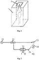
Fig. 1 shows a perspective view of a millimeter wave security check gate in accordance with one embodiment of the present disclosure; -
Fig. 2 shows a schematic diagram of a top millimeter wave imaging system in accordance with one exemplary embodiment of the present disclosure; -
Fig. 3 shows a schematic diagram of a top millimeter wave imaging system in accordance with another exemplary embodiment of the present disclosure; -
Fig. 4 shows a schematic diagram of a top millimeter wave imaging system in accordance with yet another exemplary embodiment of the present disclosure; -
Fig. 5 shows arrangements of transmitting antenna units and receiving antenna units of a top millimeter wave imaging system in accordance with the present disclosure. - Although the present disclosure will be fully described with reference to the accompanying drawings with preferred embodiments of the present disclosure, it should be understood that those skilled in the art may modify the disclosure described herein while achieving the technical effects of the present disclosure. Therefore, it is understood that the above description is broadly disclosed for those skilled in the art, and is not intended to limit the exemplary embodiments described herein.
- In addition, in the following detailed description, for ease of explanation, numerous specific details are set forth to provide a thorough understanding of embodiments of the present disclosure. However, it is clear that one or more of the embodiments may be practiced without these specific details. In other instances, well-known structures and devices are illustrated graphically to simplify the accompanying drawings.
- According to a general inventive concept of the present disclosure, a millimeter wave security check gate may be provided, comprising: a gate body; and a top millimeter wave imaging system, comprising: a millimeter wave transceiving antenna array disposed at a top of the gate body, wherein the millimeter wave transceiving antenna array comprises at least one transmitting antenna unit and a plurality of receiving antenna units; and a millimeter wave signal source connected with the millimeter wave transceiving antenna array.
-
Fig. 1 is a perspective view showing a millimeter wave security check gate in accordance with one embodiment of the present disclosure.Fig. 2 is a schematic diagram showing a top millimeter wave imaging system in accordance with one exemplary embodiment of the present disclosure. - As shown in
Fig. 1 and Fig. 2 , a millimeter wave security check gate according to one exemplary embodiment of the present disclosure may comprise a gate body 1 and a top millimeterwave imaging system 2. The top millimeterwave imaging system 2 may comprise a millimeter wave transceiving antenna array disposed at a top of the gate body 1, wherein the millimeter wave transceiving antenna array may comprise at least one transmittingantenna unit 23 and a plurality of receivingantenna units 24. Moreover, the top millimeterwave imaging system 2 may further comprise a millimeterwave signal source 21 connected with the millimeter wave transceiving antenna array, and the millimeterwave signal source 21 may be a broadband millimeterwave signal source 21 with a ultra-low power (e.g., less than 1 mw). The millimeterwave signal source 21 may emit a millimeter wave signal through the transmittingantenna unit 23 located at the top of the gate body 1, and the millimeter wave signal may irradiate a top of an object to be detected within the gate body 1, for example, a head of a human body. The millimeter wave signal reflected by the top of the object to be detected may be received by the receivingantenna unit 24 which is also located at the top of the gate body 1, to generate millimeter wave image information. Through adding the top millimeterwave imaging system 2 at the top of the gate body 1, the millimeter wave security check gate according to exemplary embodiments of the present disclosure may be able to irradiate the top of the object to be detected, thereby enhancing a detection for concealed contrabands in the top of the object to be detected (e.g., contrabands in headscarf, hair, etc.), and achieving an all-dimensional detection. - As shown in
Fig. 2 , the millimeter wave security check gate according to one exemplary embodiment of the present disclosure may further comprise abeam splitter 22 and ademodulator 25. Thebeam splitter 22 may be configured to split the millimeter wave signal emitted by the millimeterwave signal source 21 into two millimeter wave signals: a first millimeter wave signal and a second millimeter wave signal, wherein the first millimeter wave signal (as a transmitted signal) may form a wide beam millimeter wave through thetransmitting antenna unit 23 to irradiate the top of the object to be detected within the gate body 1, and the second millimeter wave signal (as a reference signal) may be inputted to thedemodulator 25. Millimeter wave signals that are reflected by the top of the object to be detected may be received by the plurality of receivingantenna units 24 to form measurement signals which may be inputted to thedemodulator 25. Thedemodulator 25 may demodulate the received measurement signals based on the reference signal to obtain a complex signal comprising target amplitude and phase information, and the real and imaginary parts of which may be I and Q, respectively, thereby imaging the top position of the object to be detected. In this embodiment, to enable the reception of the plurality of receivingantenna units 24, the top millimeter wave imaging system may further comprise aswitch 26 configured to switch the plurality of transmittingantenna units 24 quickly. - As shown in
Fig. 3 , in one exemplary embodiment, thedemodulator 25 may be a multi-channel digital demodulator 25', and the multi-channel digital demodulator 25' may simultaneously receive the second millimeter wave signals that are reflected back by the top of the object to be detected and received by the plurality of receivingantenna units 24 as the measurement signals, and then demodulate the measurement signals. In this manner, multiple I/Q signals may be obtained by digital signal processing methods after a A/D conversion of the measurement signals and reference signal in the multi-channel digital demodulator 25', that is, amplitudes and phases of the second millimeter wave signals that are reflected by the top of the object to be detected may be obtained by a coherent measurement, thereby achieving a high resolution imaging of the top position of the object to be detected. - In addition, the top millimeter wave imaging system may also employ a non-coherent imaging method. As shown in
Fig. 4 , in one exemplary embodiment, a multi-channel analog-to-digital converter 27 may be further comprised. The millimeter wave signal emitted by the millimeter wave signal source 21 (as a transmitted signal) may form a wide beam millimeter wave through the transmittingantenna unit 23 to irradiate the top of the object to be detected, and the multi-channel analog-to-digital converter 27 may simultaneously receive millimeter wave signals that are reflected by the top of the object to be detected and received by the plurality of receivingantenna units 24, and perform an analog-to-digital conversion to obtain strength information of the millimeter wave signals. In this embodiment, the plurality of receivingantenna units 24 may be arranged throughout the whole receiving plane, and these receivingantenna units 24 may simultaneously receive millimeter wave signals that are reflected by the object to be detected. -
Fig. 5 shows several arrangements of the transmittingantenna units 23 and the receivingantenna units 24 of the top millimeterwave imaging system 2. InFig. 5 , "○" may represent the transmittingantenna units 23 and "□" may represent thereceiving antenna units 24. - As shown in
Fig. 5(a) , in one exemplary embodiment, the transmittingantenna unit 23 may comprise a transmitting antenna unit, and the transmittingantenna unit 23 may be at a center of a rectangular imaging visual field of the top millimeterwave imaging system 2. The plurality of receivingantenna units 24 may be arranged along an edge of the rectangular imaging visual field. - As shown in
Fig. 5(b) , in one exemplary embodiment, the transmittingantenna unit 23 may comprise a transmitting antenna unit, and the transmittingantenna unit 23 may be at a center of a rectangular imaging visual field of the top millimeterwave imaging system 2. The plurality of receivingantenna units 24 may be arranged in a two-dimensional grid within the rectangular imaging visual field, that is, the plurality of receivingantenna units 24 may be arranged throughout the whole imaging visual field. - As shown in
Fig. 5(c) , in one exemplary embodiment, the transmittingantenna unit 23 may comprise a transmitting antenna unit, and the transmittingantenna unit 23 may be at a center of a rectangular imaging visual field of the top millimeterwave imaging system 2. The plurality of receivingantenna units 24 may be arranged randomly within the imaging visual field. - As shown in
Fig. 5(d) , in one exemplary embodiment, the transmittingantenna units 23 may comprise a plurality of transmitting antenna units, and the top millimeterwave imaging system 2 may further comprise a switch configured to switch the plurality of transmittingantenna units 23 such that only one of the plurality of transmittingantenna units 23 may emit a millimeter wave at any time. In such case, the plurality of transmittingantenna units 23 may be arranged along two parallel edges of a rectangular imaging visual field of the top millimeterwave imaging system 2, and the plurality of receivingantenna units 24 may be arranged along another two parallel edges of the rectangular imaging visual field of the top millimeterwave imaging system 2, such that the transmitting and receiving are correlated respectively. - Through disposing a top millimeter wave imaging system at the top of the gate body, the millimeter wave security check gate according to the above various embodiments of the present disclosure may be able to increase an irradiation angle of view on the top of the object to be detected, thereby enhancing a detection for concealed contrabands in the top of the object to be detected, and achieving an all-dimensional detection.
- It will be understood by those skilled in the art that the embodiments described above are exemplary and may be modified, and the structures described in the various embodiments may be combined without any conflict in structure or principle.
- After the preferred embodiments of the present disclosure have been described in detail, those skilled in the art will understand that various changes and modifications may be made without departing from the protection scope of the appended claims, and that the present disclosure is not limited to the exemplary embodiments described herein.
Claims (10)
- A millimeter wave security check gate, characterized by comprising:a gate body (1); anda top millimeter wave imaging system (2), comprising:a millimeter wave transceiving antenna array disposed at a top of the gate body (1), wherein the millimeter wave transceiving antenna array comprises at least one transmitting antenna unit (23) and a plurality of receiving antenna units (24); anda millimeter wave signal source (21) connected with the millimeter wave transceiving antenna array.
- The millimeter wave security check gate of claim 1, wherein the top millimeter wave imaging system (2) further comprises:a beam splitter (22) configured to split a millimeter wave signal emitted by the millimeter wave signal source (21) into a first millimeter wave signal and a second millimeter wave signal, wherein the first millimeter wave signal irradiates a top of an object to be detected within the gate body (1) through the at least one transmitting antenna unit (23); anda demodulator (25) configured to receive the second millimeter wave signal from the beam splitter (22) as a reference signal and receive second millimeter wave signals that are reflected by the top of the object to be detected and received by the plurality of receiving antenna units (24) as measurement signals, and then demodulate the measurement signals.
- The millimeter wave security check gate of claim 2, wherein the demodulator (25) is a multi-channel demodulator (25'), and the multi-channel demodulator (25') simultaneously receives the second millimeter wave signals that are reflected by the top of the object to be detected and received by the plurality of receiving antenna units (24) as the measurement signals, and then demodulates the measurement signals.
- The millimeter wave security check gate of claim 1, wherein the millimeter wave signal source (21) emits a millimeter wave signal through the at least one transmitting antenna unit (23), and the millimeter wave signal is to irradiate a top of an object to be detected within the gate body (1); and the top millimeter wave imaging system (2) further comprises a multi-channel analog-to-digital converter (27) to simultaneously receive millimeter wave signals that are reflected by the top of the object to be detected and received by the plurality of receiving antenna units (24), and to perform an analog-to-digital conversion to obtain strength information of the millimeter wave signals.
- The millimeter wave security check gate of any of claims 1-4, wherein a number of the at least one transmitting antenna unit (23) is one, and the transmitting antenna unit (23) is at a center of a rectangular imaging visual field of the top millimeter wave imaging system (2).
- The millimeter wave security check gate of claim 5, wherein the plurality of receiving antenna units (24) are arranged along an edge of the rectangular imaging visual field.
- The millimeter wave security check gate of claim 5, wherein the plurality of receiving antenna units (24) are arranged in a two-dimensional grid within the rectangular imaging visual field.
- The millimeter wave security check gate of claim 5, wherein the plurality of receiving antenna units (24) are arranged randomly within the rectangular imaging visual field.
- The millimeter wave security check gate of any of claims 1-4, wherein a number of the at least one transmitting antenna unit (23) is more than one, and the top millimeter wave imaging system (2) further comprises a switch (26) configured to switch the plurality of transmitting antenna units (23) such that only one of the plurality of transmitting antenna units (23) emits a millimeter wave at any time.
- The millimeter wave security check gate of claim 9, wherein the plurality of transmitting antenna units (23) are arranged along two parallel edges of a rectangular imaging visual field of the top millimeter wave imaging system (2), and the plurality of receiving antenna units (24) are arranged along another two parallel edges of the rectangular imaging visual field of the top millimeter wave imaging system (2).
Applications Claiming Priority (1)
| Application Number | Priority Date | Filing Date | Title |
|---|---|---|---|
| CN201811629832.4A CN109490980A (en) | 2018-12-28 | 2018-12-28 | Millimeter wave detector gate |
Publications (1)
| Publication Number | Publication Date |
|---|---|
| EP3674748A1 true EP3674748A1 (en) | 2020-07-01 |
Family
ID=65713158
Family Applications (1)
| Application Number | Title | Priority Date | Filing Date |
|---|---|---|---|
| EP19208834.2A Pending EP3674748A1 (en) | 2018-12-28 | 2019-11-13 | Millimeter wave security check gate |
Country Status (3)
| Country | Link |
|---|---|
| US (1) | US20200209384A1 (en) |
| EP (1) | EP3674748A1 (en) |
| CN (1) | CN109490980A (en) |
Families Citing this family (4)
| Publication number | Priority date | Publication date | Assignee | Title |
|---|---|---|---|---|
| CN109917480A (en) * | 2019-03-21 | 2019-06-21 | 安徽启路达光电科技有限公司 | A kind of active Terahertz safety check apparatus |
| CN111175748A (en) * | 2019-12-24 | 2020-05-19 | 北京华研微波科技有限公司 | Millimeter wave antenna array |
| CN111564697A (en) * | 2020-05-02 | 2020-08-21 | 成都睿识智能科技有限公司 | Active electric scanning array antenna for portable security inspection equipment and antenna system |
| CN112099001B (en) * | 2020-09-18 | 2021-09-03 | 欧必翼太赫兹科技(北京)有限公司 | Control method of three-dimensional special-shaped planar aperture holographic imaging security inspection radar |
Citations (4)
| Publication number | Priority date | Publication date | Assignee | Title |
|---|---|---|---|---|
| US20130100774A1 (en) * | 2010-04-20 | 2013-04-25 | Christopher Brown | System for determining the distance from and the direction to an object |
| US20170227636A1 (en) * | 2015-12-17 | 2017-08-10 | William F. Moulder | Methods and systems for near-field microwave imaging |
| WO2018032669A1 (en) * | 2016-08-18 | 2018-02-22 | 华讯方舟科技有限公司 | Millimeter wave imaging-based omni-directional security detection system |
| EP3287816A1 (en) * | 2016-08-25 | 2018-02-28 | Nuctech Company Limited | Millimeter-wave imaging system |
Family Cites Families (11)
| Publication number | Priority date | Publication date | Assignee | Title |
|---|---|---|---|---|
| US6486828B1 (en) * | 2000-07-26 | 2002-11-26 | Western Multiplex | Adaptive array antenna nulling |
| GB0211161D0 (en) * | 2002-05-16 | 2002-06-26 | Qinetiq Ltd | Millimetre-wave illumination source |
| US7385549B2 (en) * | 2003-08-12 | 2008-06-10 | Trex Enterprises Corp | Millimeter wave portal imaging system |
| CN102393536B (en) * | 2011-10-30 | 2014-10-22 | 北京无线电计量测试研究所 | Scanning method for human body security check system utilizing frequency division and space division |
| CN103698762B (en) * | 2013-12-30 | 2016-11-23 | 北京无线电计量测试研究所 | A kind of virtual axis type millimeter wave human body security check system |
| CN110632593A (en) * | 2015-12-25 | 2019-12-31 | 华讯方舟科技有限公司 | Human body security check system and method based on millimeter wave holographic three-dimensional imaging |
| CN105607056A (en) * | 2015-12-28 | 2016-05-25 | 深圳市太赫兹科技创新研究院 | Human body security check system and method |
| CN105699494B (en) * | 2015-12-28 | 2018-08-17 | 深圳市太赫兹科技创新研究院 | Millimeter wave hologram three-dimensional image-forming detecting system and method |
| CN105467386B (en) * | 2015-12-28 | 2019-01-01 | 同方威视技术股份有限公司 | Millimeter wave 3D hologram scanning imagery equipment |
| CN106094048A (en) * | 2016-07-26 | 2016-11-09 | 华讯方舟科技有限公司 | Portable security inspection equipment based on mm-wave imaging |
| CN209690537U (en) * | 2018-12-28 | 2019-11-26 | 同方威视技术股份有限公司 | Millimeter wave detector gate |
-
2018
- 2018-12-28 CN CN201811629832.4A patent/CN109490980A/en active Pending
-
2019
- 2019-11-13 EP EP19208834.2A patent/EP3674748A1/en active Pending
- 2019-11-14 US US16/683,365 patent/US20200209384A1/en not_active Abandoned
Patent Citations (4)
| Publication number | Priority date | Publication date | Assignee | Title |
|---|---|---|---|---|
| US20130100774A1 (en) * | 2010-04-20 | 2013-04-25 | Christopher Brown | System for determining the distance from and the direction to an object |
| US20170227636A1 (en) * | 2015-12-17 | 2017-08-10 | William F. Moulder | Methods and systems for near-field microwave imaging |
| WO2018032669A1 (en) * | 2016-08-18 | 2018-02-22 | 华讯方舟科技有限公司 | Millimeter wave imaging-based omni-directional security detection system |
| EP3287816A1 (en) * | 2016-08-25 | 2018-02-28 | Nuctech Company Limited | Millimeter-wave imaging system |
Also Published As
| Publication number | Publication date |
|---|---|
| CN109490980A (en) | 2019-03-19 |
| US20200209384A1 (en) | 2020-07-02 |
Similar Documents
| Publication | Publication Date | Title |
|---|---|---|
| EP3674748A1 (en) | Millimeter wave security check gate | |
| US10551490B2 (en) | Security inspection system and method using the three-dimensional holographic imaging technology | |
| EP2191292B1 (en) | Imaging system and method | |
| CN105510911B (en) | Based on chirped more people's human body rays safety detection apparatus and method | |
| US9885777B2 (en) | Detection of stealth vehicles using VHF radar | |
| WO2020098018A1 (en) | Data acquisition system of active millimeter-wave imaging radar and acquisition method therefor | |
| CN205608180U (en) | Three -dimensional holographic imaging's security inspection system | |
| AU2010310879B2 (en) | Wide area detection of insects using reflected microwaves | |
| CA2744476A1 (en) | Circularly polarized antennas for active holographic imaging through barriers | |
| RU2004102190A (en) | METHOD FOR IMPROVING RADAR RESOLUTION, SYSTEM FOR ITS IMPLEMENTATION AND METHOD FOR REMOTE IDENTIFICATION OF THE SYSTEM OF SMALL-SIZED OBJECTS | |
| Kapilevich et al. | Detecting hidden objects on human body using active millimeter wave sensor | |
| RU2019107125A (en) | RADAR SYSTEM | |
| US4306239A (en) | Microwave landing systems | |
| Astapenya et al. | Experimental evaluation of the shading effect of accelerating lens in azimuth plane | |
| ATE538396T1 (en) | SAFETY SYSTEM WITH MM WAVE IMAGE | |
| WO2013037701A1 (en) | Interferometric scanning system and method | |
| CN107505592B (en) | Communication access method based on multi-beam radar rough direction finding | |
| JP6415118B2 (en) | Interference suppression device and interference suppression system | |
| RU2127437C1 (en) | Method of radar fixing of coordinates of targets | |
| Wang et al. | Experimental assessment of the cross coupling and polarization effects on ultra-wide band see-through-wall imaging reconstruction | |
| Cattenoz et al. | An experimental demonstration of a posteriori digital calibration of MIMO radar system | |
| Rappaport et al. | Multistatic nearfield imaging radar for portal security systems using a high gain toroidal reflector antenna | |
| RU2582088C1 (en) | Method for radar scanning of space (versions) | |
| JPH0713657B2 (en) | Bistatic radar device | |
| JP2005121421A (en) | Rcs measuring system for sea |
Legal Events
| Date | Code | Title | Description |
|---|---|---|---|
| PUAI | Public reference made under article 153(3) epc to a published international application that has entered the european phase |
Free format text: ORIGINAL CODE: 0009012 |
|
| STAA | Information on the status of an ep patent application or granted ep patent |
Free format text: STATUS: THE APPLICATION HAS BEEN PUBLISHED |
|
| AK | Designated contracting states |
Kind code of ref document: A1 Designated state(s): AL AT BE BG CH CY CZ DE DK EE ES FI FR GB GR HR HU IE IS IT LI LT LU LV MC MK MT NL NO PL PT RO RS SE SI SK SM TR |
|
| AX | Request for extension of the european patent |
Extension state: BA ME |
|
| STAA | Information on the status of an ep patent application or granted ep patent |
Free format text: STATUS: REQUEST FOR EXAMINATION WAS MADE |
|
| 17P | Request for examination filed |
Effective date: 20201102 |
|
| RBV | Designated contracting states (corrected) |
Designated state(s): AL AT BE BG CH CY CZ DE DK EE ES FI FR GB GR HR HU IE IS IT LI LT LU LV MC MK MT NL NO PL PT RO RS SE SI SK SM TR |
|
| STAA | Information on the status of an ep patent application or granted ep patent |
Free format text: STATUS: EXAMINATION IS IN PROGRESS |
|
| 17Q | First examination report despatched |
Effective date: 20221223 |