EP3674626A1 - Stirling cycle cooling device with integral mounting - Google Patents
Stirling cycle cooling device with integral mounting Download PDFInfo
- Publication number
- EP3674626A1 EP3674626A1 EP19219632.7A EP19219632A EP3674626A1 EP 3674626 A1 EP3674626 A1 EP 3674626A1 EP 19219632 A EP19219632 A EP 19219632A EP 3674626 A1 EP3674626 A1 EP 3674626A1
- Authority
- EP
- European Patent Office
- Prior art keywords
- bearing
- piston
- support
- crankshaft
- axis
- Prior art date
- Legal status (The legal status is an assumption and is not a legal conclusion. Google has not performed a legal analysis and makes no representation as to the accuracy of the status listed.)
- Granted
Links
- 238000001816 cooling Methods 0.000 title claims abstract description 29
- 230000006835 compression Effects 0.000 description 11
- 238000007906 compression Methods 0.000 description 11
- 238000004519 manufacturing process Methods 0.000 description 8
- 239000012530 fluid Substances 0.000 description 7
- 230000008929 regeneration Effects 0.000 description 7
- 238000011069 regeneration method Methods 0.000 description 7
- 239000000314 lubricant Substances 0.000 description 5
- 230000007246 mechanism Effects 0.000 description 5
- 238000004804 winding Methods 0.000 description 4
- 108020005351 Isochores Proteins 0.000 description 2
- 239000000853 adhesive Substances 0.000 description 2
- 230000001070 adhesive effect Effects 0.000 description 2
- 239000000356 contaminant Substances 0.000 description 2
- 238000006073 displacement reaction Methods 0.000 description 2
- 238000000034 method Methods 0.000 description 2
- 239000003507 refrigerant Substances 0.000 description 2
- 238000005096 rolling process Methods 0.000 description 2
- 230000035939 shock Effects 0.000 description 2
- OKTJSMMVPCPJKN-UHFFFAOYSA-N Carbon Chemical compound [C] OKTJSMMVPCPJKN-UHFFFAOYSA-N 0.000 description 1
- 230000005534 acoustic noise Effects 0.000 description 1
- 230000000712 assembly Effects 0.000 description 1
- 238000000429 assembly Methods 0.000 description 1
- 229910052799 carbon Inorganic materials 0.000 description 1
- 230000008859 change Effects 0.000 description 1
- 238000010276 construction Methods 0.000 description 1
- 238000011109 contamination Methods 0.000 description 1
- 230000008094 contradictory effect Effects 0.000 description 1
- 238000005520 cutting process Methods 0.000 description 1
- 238000009826 distribution Methods 0.000 description 1
- 238000010438 heat treatment Methods 0.000 description 1
- 238000003754 machining Methods 0.000 description 1
- 230000009467 reduction Effects 0.000 description 1
- 239000007787 solid Substances 0.000 description 1
- 238000007711 solidification Methods 0.000 description 1
- 230000008023 solidification Effects 0.000 description 1
Images


Classifications
-
- F—MECHANICAL ENGINEERING; LIGHTING; HEATING; WEAPONS; BLASTING
- F25—REFRIGERATION OR COOLING; COMBINED HEATING AND REFRIGERATION SYSTEMS; HEAT PUMP SYSTEMS; MANUFACTURE OR STORAGE OF ICE; LIQUEFACTION SOLIDIFICATION OF GASES
- F25B—REFRIGERATION MACHINES, PLANTS OR SYSTEMS; COMBINED HEATING AND REFRIGERATION SYSTEMS; HEAT PUMP SYSTEMS
- F25B9/00—Compression machines, plants or systems, in which the refrigerant is air or other gas of low boiling point
- F25B9/14—Compression machines, plants or systems, in which the refrigerant is air or other gas of low boiling point characterised by the cycle used, e.g. Stirling cycle
-
- F—MECHANICAL ENGINEERING; LIGHTING; HEATING; WEAPONS; BLASTING
- F04—POSITIVE - DISPLACEMENT MACHINES FOR LIQUIDS; PUMPS FOR LIQUIDS OR ELASTIC FLUIDS
- F04B—POSITIVE-DISPLACEMENT MACHINES FOR LIQUIDS; PUMPS
- F04B39/00—Component parts, details, or accessories, of pumps or pumping systems specially adapted for elastic fluids, not otherwise provided for in, or of interest apart from, groups F04B25/00 - F04B37/00
- F04B39/06—Cooling; Heating; Prevention of freezing
-
- F—MECHANICAL ENGINEERING; LIGHTING; HEATING; WEAPONS; BLASTING
- F02—COMBUSTION ENGINES; HOT-GAS OR COMBUSTION-PRODUCT ENGINE PLANTS
- F02G—HOT GAS OR COMBUSTION-PRODUCT POSITIVE-DISPLACEMENT ENGINE PLANTS; USE OF WASTE HEAT OF COMBUSTION ENGINES; NOT OTHERWISE PROVIDED FOR
- F02G1/00—Hot gas positive-displacement engine plants
- F02G1/04—Hot gas positive-displacement engine plants of closed-cycle type
- F02G1/043—Hot gas positive-displacement engine plants of closed-cycle type the engine being operated by expansion and contraction of a mass of working gas which is heated and cooled in one of a plurality of constantly communicating expansible chambers, e.g. Stirling cycle type engines
- F02G1/044—Hot gas positive-displacement engine plants of closed-cycle type the engine being operated by expansion and contraction of a mass of working gas which is heated and cooled in one of a plurality of constantly communicating expansible chambers, e.g. Stirling cycle type engines having at least two working members, e.g. pistons, delivering power output
-
- F—MECHANICAL ENGINEERING; LIGHTING; HEATING; WEAPONS; BLASTING
- F04—POSITIVE - DISPLACEMENT MACHINES FOR LIQUIDS; PUMPS FOR LIQUIDS OR ELASTIC FLUIDS
- F04B—POSITIVE-DISPLACEMENT MACHINES FOR LIQUIDS; PUMPS
- F04B35/00—Piston pumps specially adapted for elastic fluids and characterised by the driving means to their working members, or by combination with, or adaptation to, specific driving engines or motors, not otherwise provided for
- F04B35/04—Piston pumps specially adapted for elastic fluids and characterised by the driving means to their working members, or by combination with, or adaptation to, specific driving engines or motors, not otherwise provided for the means being electric
-
- F—MECHANICAL ENGINEERING; LIGHTING; HEATING; WEAPONS; BLASTING
- F04—POSITIVE - DISPLACEMENT MACHINES FOR LIQUIDS; PUMPS FOR LIQUIDS OR ELASTIC FLUIDS
- F04B—POSITIVE-DISPLACEMENT MACHINES FOR LIQUIDS; PUMPS
- F04B39/00—Component parts, details, or accessories, of pumps or pumping systems specially adapted for elastic fluids, not otherwise provided for in, or of interest apart from, groups F04B25/00 - F04B37/00
- F04B39/0005—Component parts, details, or accessories, of pumps or pumping systems specially adapted for elastic fluids, not otherwise provided for in, or of interest apart from, groups F04B25/00 - F04B37/00 adaptations of pistons
-
- F—MECHANICAL ENGINEERING; LIGHTING; HEATING; WEAPONS; BLASTING
- F04—POSITIVE - DISPLACEMENT MACHINES FOR LIQUIDS; PUMPS FOR LIQUIDS OR ELASTIC FLUIDS
- F04B—POSITIVE-DISPLACEMENT MACHINES FOR LIQUIDS; PUMPS
- F04B39/00—Component parts, details, or accessories, of pumps or pumping systems specially adapted for elastic fluids, not otherwise provided for in, or of interest apart from, groups F04B25/00 - F04B37/00
- F04B39/0027—Pulsation and noise damping means
-
- F—MECHANICAL ENGINEERING; LIGHTING; HEATING; WEAPONS; BLASTING
- F04—POSITIVE - DISPLACEMENT MACHINES FOR LIQUIDS; PUMPS FOR LIQUIDS OR ELASTIC FLUIDS
- F04B—POSITIVE-DISPLACEMENT MACHINES FOR LIQUIDS; PUMPS
- F04B39/00—Component parts, details, or accessories, of pumps or pumping systems specially adapted for elastic fluids, not otherwise provided for in, or of interest apart from, groups F04B25/00 - F04B37/00
- F04B39/0094—Component parts, details, or accessories, of pumps or pumping systems specially adapted for elastic fluids, not otherwise provided for in, or of interest apart from, groups F04B25/00 - F04B37/00 crankshaft
-
- F—MECHANICAL ENGINEERING; LIGHTING; HEATING; WEAPONS; BLASTING
- F04—POSITIVE - DISPLACEMENT MACHINES FOR LIQUIDS; PUMPS FOR LIQUIDS OR ELASTIC FLUIDS
- F04B—POSITIVE-DISPLACEMENT MACHINES FOR LIQUIDS; PUMPS
- F04B39/00—Component parts, details, or accessories, of pumps or pumping systems specially adapted for elastic fluids, not otherwise provided for in, or of interest apart from, groups F04B25/00 - F04B37/00
- F04B39/12—Casings; Cylinders; Cylinder heads; Fluid connections
- F04B39/122—Cylinder block
-
- H—ELECTRICITY
- H02—GENERATION; CONVERSION OR DISTRIBUTION OF ELECTRIC POWER
- H02K—DYNAMO-ELECTRIC MACHINES
- H02K1/00—Details of the magnetic circuit
- H02K1/06—Details of the magnetic circuit characterised by the shape, form or construction
- H02K1/12—Stationary parts of the magnetic circuit
- H02K1/18—Means for mounting or fastening magnetic stationary parts on to, or to, the stator structures
- H02K1/187—Means for mounting or fastening magnetic stationary parts on to, or to, the stator structures to inner stators
-
- H—ELECTRICITY
- H02—GENERATION; CONVERSION OR DISTRIBUTION OF ELECTRIC POWER
- H02K—DYNAMO-ELECTRIC MACHINES
- H02K1/00—Details of the magnetic circuit
- H02K1/06—Details of the magnetic circuit characterised by the shape, form or construction
- H02K1/22—Rotating parts of the magnetic circuit
- H02K1/27—Rotor cores with permanent magnets
- H02K1/2786—Outer rotors
-
- H—ELECTRICITY
- H02—GENERATION; CONVERSION OR DISTRIBUTION OF ELECTRIC POWER
- H02K—DYNAMO-ELECTRIC MACHINES
- H02K7/00—Arrangements for handling mechanical energy structurally associated with dynamo-electric machines, e.g. structural association with mechanical driving motors or auxiliary dynamo-electric machines
- H02K7/18—Structural association of electric generators with mechanical driving motors, e.g. with turbines
- H02K7/1807—Rotary generators
- H02K7/1815—Rotary generators structurally associated with reciprocating piston engines
-
- F—MECHANICAL ENGINEERING; LIGHTING; HEATING; WEAPONS; BLASTING
- F02—COMBUSTION ENGINES; HOT-GAS OR COMBUSTION-PRODUCT ENGINE PLANTS
- F02G—HOT GAS OR COMBUSTION-PRODUCT POSITIVE-DISPLACEMENT ENGINE PLANTS; USE OF WASTE HEAT OF COMBUSTION ENGINES; NOT OTHERWISE PROVIDED FOR
- F02G1/00—Hot gas positive-displacement engine plants
- F02G1/04—Hot gas positive-displacement engine plants of closed-cycle type
- F02G1/043—Hot gas positive-displacement engine plants of closed-cycle type the engine being operated by expansion and contraction of a mass of working gas which is heated and cooled in one of a plurality of constantly communicating expansible chambers, e.g. Stirling cycle type engines
- F02G1/053—Component parts or details
- F02G1/055—Heaters or coolers
-
- F—MECHANICAL ENGINEERING; LIGHTING; HEATING; WEAPONS; BLASTING
- F02—COMBUSTION ENGINES; HOT-GAS OR COMBUSTION-PRODUCT ENGINE PLANTS
- F02G—HOT GAS OR COMBUSTION-PRODUCT POSITIVE-DISPLACEMENT ENGINE PLANTS; USE OF WASTE HEAT OF COMBUSTION ENGINES; NOT OTHERWISE PROVIDED FOR
- F02G1/00—Hot gas positive-displacement engine plants
- F02G1/04—Hot gas positive-displacement engine plants of closed-cycle type
- F02G1/043—Hot gas positive-displacement engine plants of closed-cycle type the engine being operated by expansion and contraction of a mass of working gas which is heated and cooled in one of a plurality of constantly communicating expansible chambers, e.g. Stirling cycle type engines
- F02G1/053—Component parts or details
- F02G1/057—Regenerators
-
- F—MECHANICAL ENGINEERING; LIGHTING; HEATING; WEAPONS; BLASTING
- F02—COMBUSTION ENGINES; HOT-GAS OR COMBUSTION-PRODUCT ENGINE PLANTS
- F02G—HOT GAS OR COMBUSTION-PRODUCT POSITIVE-DISPLACEMENT ENGINE PLANTS; USE OF WASTE HEAT OF COMBUSTION ENGINES; NOT OTHERWISE PROVIDED FOR
- F02G2244/00—Machines having two pistons
- F02G2244/50—Double acting piston machines
-
- F—MECHANICAL ENGINEERING; LIGHTING; HEATING; WEAPONS; BLASTING
- F02—COMBUSTION ENGINES; HOT-GAS OR COMBUSTION-PRODUCT ENGINE PLANTS
- F02G—HOT GAS OR COMBUSTION-PRODUCT POSITIVE-DISPLACEMENT ENGINE PLANTS; USE OF WASTE HEAT OF COMBUSTION ENGINES; NOT OTHERWISE PROVIDED FOR
- F02G2270/00—Constructional features
- F02G2270/10—Rotary pistons
-
- F—MECHANICAL ENGINEERING; LIGHTING; HEATING; WEAPONS; BLASTING
- F02—COMBUSTION ENGINES; HOT-GAS OR COMBUSTION-PRODUCT ENGINE PLANTS
- F02G—HOT GAS OR COMBUSTION-PRODUCT POSITIVE-DISPLACEMENT ENGINE PLANTS; USE OF WASTE HEAT OF COMBUSTION ENGINES; NOT OTHERWISE PROVIDED FOR
- F02G2270/00—Constructional features
- F02G2270/55—Cylinders
-
- F—MECHANICAL ENGINEERING; LIGHTING; HEATING; WEAPONS; BLASTING
- F02—COMBUSTION ENGINES; HOT-GAS OR COMBUSTION-PRODUCT ENGINE PLANTS
- F02G—HOT GAS OR COMBUSTION-PRODUCT POSITIVE-DISPLACEMENT ENGINE PLANTS; USE OF WASTE HEAT OF COMBUSTION ENGINES; NOT OTHERWISE PROVIDED FOR
- F02G2270/00—Constructional features
- F02G2270/85—Crankshafts
-
- F—MECHANICAL ENGINEERING; LIGHTING; HEATING; WEAPONS; BLASTING
- F25—REFRIGERATION OR COOLING; COMBINED HEATING AND REFRIGERATION SYSTEMS; HEAT PUMP SYSTEMS; MANUFACTURE OR STORAGE OF ICE; LIQUEFACTION SOLIDIFICATION OF GASES
- F25B—REFRIGERATION MACHINES, PLANTS OR SYSTEMS; COMBINED HEATING AND REFRIGERATION SYSTEMS; HEAT PUMP SYSTEMS
- F25B2309/00—Gas cycle refrigeration machines
- F25B2309/003—Gas cycle refrigeration machines characterised by construction or composition of the regenerator
Definitions
- the invention relates to a cooling device implementing a thermodynamic cycle of the reverse Stirling type.
- a cooling device implementing a thermodynamic cycle of the reverse Stirling type.
- Such a device is for example described in the patent US4365982 .
- the cooling is carried out by means of a refrigerant circulating in a circuit mainly comprising a compressor and a regenerator used as a heat exchanger.
- the invention finds particular utility in the field of sensors and electronic components requiring cooling at low temperature.
- the temperature obtained by such a cooling device is generally in a temperature range between 40 and 250K.
- the compressor includes a compression piston movable in translation in a cylinder.
- the regenerator includes a regeneration piston also movable in a second cylinder.
- the two pistons are each driven by a connecting rod / crank system, composed of a crankshaft (which can carry one or more crankpins) and one or more connecting rods.
- the crankshaft is rotated by a rotary engine.
- the axes of movement of the two pistons are defined respectively in two generally parallel, distinct or merged planes. These planes are generally perpendicular to the axis of rotation of the crankshaft.
- the regeneration piston is driven by the crankshaft, by means of a connecting rod articulated on the one hand on the crank pin and on the other hand on the regeneration piston.
- the mechanism with three axes of movement, two axes of translation for the pistons and one axis of rotation for the crankshaft is generally hyperstatic. Hyperstatism is the result of compromises necessary to manage to combine the constraints of manufacturing and positioning of the various components of the kinematic chain of the mechanism and the constraints of acoustic and vibratory discretion imposed by the targeted applications (in particular optronics).
- lubricant in particular between the pistons and their cylinder or in the connecting rod / crank system.
- these lubricants can contaminate the refrigerant.
- contamination can lead to blockages if one of the contaminants reaches its solidification temperature.
- the cooling requirements often require reaching cold temperatures well below the temperatures of change of state of the lubricants and contaminants.
- the invention aims to overcome all or part of the problems mentioned above by proposing a device tending towards a silent and low vibration isostatic mechanism.
- the invention relates to a Stirling cycle cooling device comprising a reciprocating piston compressor driven by a rotary engine around an axis via a crankshaft.
- the device further comprises a monobloc support forming a cylinder in which the piston of the compressor moves.
- the crankshaft is supported by a single bearing which is arranged without an intermediate part in a housing of the monobloc support.
- the rotary motor comprises a stator directly fixed to the monobloc support.
- the device advantageously further comprises a reciprocating piston regenerator driven by the rotary engine via the crankshaft.
- the monobloc support then forms a cylinder in which the piston of the regenerator moves.
- the compressor piston and / or the regenerator piston advantageously slide in the one-piece support without any intermediate mechanical part and in particular without the presence of a jacket between the support and the corresponding piston.
- the bearing is advantageously disposed between a crankpin of the crankshaft and the rotary engine and supports a rotor of the rotary engine.
- the bearing may include at least one outer ring advantageously made directly in the one-piece support.
- the bearing can include two bearings.
- the outer rings of the bearings are advantageously made in the one-piece support.
- the rotary motor comprises an internal stator and an external rotor.
- the internal stator advantageously has a cylindrical shape open axially along the axis.
- the monobloc support comprises a tubular bearing extending along the axis.
- the stator is fixed on the outside of the tubular bearing.
- the interior of the tubular seat forms the housing.
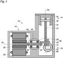
- the figure 1 shows in section a cooling device 10 implementing a thermodynamic cycle of the reverse Stirling type.
- the device comprises a compressor 12 driven by a rotary motor 14.
- the compressor 12 mainly comprises a reciprocating piston 16 moving in translation in a reciprocating movement in a cylinder 18.
- the piston 16 is driven by a crank pin 20 using a connecting rod 22.
- the crank pin 20 is rotated by the motor 14 around an axis 24.
- the motor 14 comprises a rotor 26 driving a motor shaft 28 integral with the crank pin 20.
- the assembly formed by the drive shaft 28 and the crank pin 20 is here designated crankshaft 46.
- the rotor 26 is disposed inside a stator 30.
- the cooling device 10 comprises a monobloc support 32.
- the support 32 is produced in a single mechanical part.
- the support 32 comprises a bore extending along an axis 34 perpendicular to the axis 24.
- the bore forms the cylinder 18 in which the piston 16 moves.
- a jacket 36 carried by the support 32 is interposed between the support 32 and the piston 16.
- the support 32 further comprises a housing 38 in which is located a bearing 40 supporting the crankshaft 46.
- the bearing 40 is disposed in the housing 38 without intermediate piece between the bearing 40 and the housing 38.
- the monobloc support 32 is advantageously produced without assembly.
- an assembly can be accepted provided that the bore forming the cylinder 18 as well as the housing 38 receiving the bearing 40 are machined after assembly. This machining carried out after assembly makes it possible to prevent the tolerances of the assembly from coming to cumulate with that connecting the cylinder 18 and the housing 38.
- one-piece means a mechanical part whose manufacturing tolerances are not not impacted by any assembly that may occur during its manufacturing process.
- having the bearing 40 in the support 32 without an intermediate part makes it possible to limit the dimension chains between the cylinder 18 and the crankshaft 46. No intermediate mechanical part whose dimensions would lengthen the dimension chain is located between the housing 38 and the bearing 40.
- the axis 24 is defined as the axis of rotation of the bearing 40.
- a single bearing 40 carries the rotating part of the cooling device 10 formed by the rotor 26 and the crankshaft 46. This single bearing 40 makes it possible to facilitate the production of the support 32. Indeed, it would be possible to support the rotating part by means of two bearings, for example located on either side of the crankshaft. However, this provision imposes tolerances of tight manufacturing to align the two bearings along axis 24. A single bearing avoids this alignment constraint.
- the housing 38 generally has a form of bore extending along the axis 24. In order to limit the overhang of the motor shaft, the housing 38 is located between the motor 14 and the crank pin 20. Alternatively, it is also possible to arrange the housing 38 and therefore the bearing 40 on the other side of the motor 14 or on the other side of the crank pin 20. However the position of the bearing 40 between the motor 14 and the crank pin 20 allows better distribution the loads supported by the bearing 40, exerted in particular by the compressor 12 and by the motor 14.
- the bearing 40 is for example formed of two bearings 42 and 44, the outer rings of which are integral with the housing 38 and the inner rings of which carry the motor shaft 28.
- the bearings 42 and 44 can be combined in the form, for example, of a bearing double row of rolling elements with a common outer ring and two separate inner rings in order to limit the clearances in the bearing 40 as much as possible.
- the bearings can be replaced by a plain bearing.
- the outer rings of the bearings 42 and 44 or the outer ring of the plain bearing can be fixed to the support 32 by means of a tight fit and / or adhesive placed between the outer ring (s) and the support 32. This adhesive does not constitute an intermediate mechanical part between the support 32 and the bearing 40.
- the outer ring of the plain bearing can be directly produced in the monobloc support 32.
- stator 30 of the motor 14 It is also possible to fix the stator 30 of the motor 14 directly on the support 32. This simplifies the dimension chain making it possible to define the functional clearance between the stator 30 and the rotor 26. This dimension chain only passes through the stator 30, support 32, bearing 40, the motor shaft 28 and the rotor 26. No other mechanical part belonging to the equivalence class of the support 32 appears in this chain of dimensions.
- the figure 2 represents the cooling device 10 in section in a plane perpendicular to the cutting plane of the figure 1 , that is to say perpendicular to the axis 24.
- the cooling device 10 further comprises a regenerator 70 also driven in rotation by the engine 14 and more precisely by the crankshaft 46.
- the regenerator is sometimes called displacer.
- the regenerator 70 mainly comprises a reciprocating piston 72 moving in translation in a reciprocating movement in a cylinder 74 along an axis 76.
- the axis 76 of the regenerator 70 is perpendicular to the axis 34 along which the piston 16 of the compressor 12 moves. It is also possible to produce a cooling device according to the invention with other relative orientations of the axes 76 and 34.
- the piston 72 is driven by the crank pin 20 using a connecting rod 78.
- the crankshaft 46 may include a second crank pin, distinct from the crank pin 20 and driving the connecting rod 78.
- the cylinder 74 is advantageously produced in the monobloc support 32.
- the support 32 comprises a bore forming the cylinder 74.
- the regenerator bore 70 is jacketed.
- a jacket 80 carried by the support 32, is interposed between the support 32 and the piston 72.
- the figure 3 shows a variant of the cooling device 10 in section in a plane similar to that of the figure 2 .
- the compressor 12 and the regenerator 70 In the support 32 there is the bore forming the cylinder 18 of the compressor 12 and the bore forming the cylinder 74 of the regenerator 70.
- the cylinders 18 and 74 of the support 32 are not lined and the pistons 16 and 72 slide in the support 32 without an intermediate mechanical part. More precisely, the only intermediary between a piston and its cylinder can be a fluid, a fluid or solid lubricant. It is possible to keep a jacket for only one of the pistons, either for the piston 16 or for the piston 72.
- the invention is already advantageous by eliminating at least one of the two shirts 36 or 80.
- the figure 4 shows another variant of the cooling device 10 shown in the figure 1 .
- compressor 12 the regenerator 70 and the engine 14.
- the support 32 there are the bores forming the cylinders 18 and 74 as well as the housing 38 in which the bearing 40 is disposed.
- the outer rings 48 of the bearings 42 and 44 are directly produced in the support 32.
- the housing 38 is more complicated to produce but in this variant, there is no longer any adjustment to be made between the outer rings of the bearings and the support 32.
- shirt 36 appears. It is of course possible to do without this shirt as shown on the figure 3 . It is the same for the shirt 80 which we can do without in the variant of the figure 4 .
- the figure 5 shows a second cooling device 50 implementing a thermodynamic cycle of the reverse Stirling type.
- the compressor 12 whose piston 16 is driven by the crankshaft 20.
- the jacket 36 serves as an intermediary between the bore of the support 52 and the piston 16. It is of course possible to do without the jacket 36 as described using figures 2 and 4 .
- a crankshaft 65 is driven by an electric motor 54 with an external rotor.
- the reciprocating movement of the pistons in their respective cylinders generates alternating and potentially phase-shifting axial forces. These forces, exerted by the pistons, are transmitted to the crank pin 20 by the connecting rods present in the cooling device 50.
- the combination of these loads results in a resistant torque of variable amplitude at the level of the motor shaft 64. More precisely , this couple presents strong amplitude variations between a value close to zero and a maximum value reached twice per revolution. It is possible to limit the impact of these resistive torque variations on the motorization using a flywheel added to the motor shaft.
- An external rotor motor has, by construction, a moment of inertia around its axis of rotation. more important than an internal rotor motor as described on figures 1 to 4 .
- the use of an external rotor motor therefore makes it possible to combine the functions carried by the rotor and the flywheel within the same component.
- an external rotor motor can generate a torque greater than that of an internal rotor motor.
- the use of an external rotor motor therefore makes it possible to facilitate the miniaturization of the cooling device.
- the stator 56 of the motor 54 has a cylindrical shape open along the axis of rotation 24 of the motor.
- the stator 56 comprises for example windings making it possible to generate a rotating magnetic field extending radially with respect to the axis 24 at the periphery of the stator 56.
- the motor 54 comprises a rotor 58 produced in the form of a tubular segment with an axis of revolution 24.
- the rotor 58 is arranged radially around the stator 56.
- the rotor 58 may comprise windings or permanent magnets intended to hang on the magnetic field generated by the stator windings.
- the use of permanent magnets makes it possible to avoid the use of rotating contacts, such as brushes or carbon brushes, necessary for supplying the rotor windings.
- the support 52 is in one piece like the support 32 and includes a tubular bearing 60 extending along the axis 24.
- the stator 56 is fixed on the outside of the tubular bearing 60 which passes through the stator 56.
- the interior of this bearing tubular 60 forms a housing 62 in which is located the bearing 40 supporting the motor shaft 64.
- the bearing 40 is formed of two bearings 42 and 44. As before, the outer rings of the bearings 42 and 44 can be produced directly in the support 52 and more precisely inside the bearing 60.
- bearings 42 and 44 can be replaced by other mechanical components such as plain bearings.
- the two bearings 42 and 44 of the device 50 can for example be combined into a double-row bearing of rolling elements with a common outer ring and two separate inner rings.
- the embodiment of the figure 5 allows to move the bearings 42 and 44 along the axis 24, ensuring better mechanical stability to the rotating parts of the cooling device 50.
- the bearings 42 and 44 can be ball or roller.
- the bearing contacts can be straight or oblique.
- the drive shaft 64 is secured to a veil 66 arranged perpendicular to the axis 24.
- the veil 66 is secured to a tube segment 68 of axis of revolution 24.
- the rotor 58 is fixed inside the segment of tube 68.
- the motor 54 is disposed between the support 52 and the web 66.
Landscapes
- Engineering & Computer Science (AREA)
- Mechanical Engineering (AREA)
- General Engineering & Computer Science (AREA)
- Chemical & Material Sciences (AREA)
- Combustion & Propulsion (AREA)
- Power Engineering (AREA)
- Physics & Mathematics (AREA)
- Thermal Sciences (AREA)
- Compressor (AREA)
- Compressors, Vaccum Pumps And Other Relevant Systems (AREA)
Abstract
L'invention concerne un dispositif de refroidissement mettant en œuvre un cycle thermodynamique de type Stirling inversé. Le dispositif (10) comprend un compresseur (12) à piston alternatif (16) entrainé par un moteur rotatif (14) autour d'un axe (24) par l'intermédiaire d'un vilebrequin (46). Le dispositif (10) comprend en outre un support monobloc (32) formant un cylindre (18) dans lequel se déplace le piston (16) du compresseur (12). Le vilebrequin (46) est supporté par un seul palier (40). Le palier (40) est disposé sans pièce intermédiaire dans un logement (38) du support monobloc (32).The invention relates to a cooling device implementing a thermodynamic cycle of the reverse Stirling type. The device (10) comprises a reciprocating piston compressor (12) (16) driven by a rotary motor (14) around an axis (24) via a crankshaft (46). The device (10) further comprises a monobloc support (32) forming a cylinder (18) in which the piston (16) of the compressor (12) moves. The crankshaft (46) is supported by a single bearing (40). The bearing (40) is arranged without an intermediate part in a housing (38) of the monobloc support (32).
Description
L'invention concerne un dispositif de refroidissement mettant en œuvre un cycle thermodynamique de type Stirling inversé. Un tel dispositif est par exemple décrit dans le brevet
L'invention trouve une utilité particulière dans le domaine des capteurs et des composants électroniques nécessitant un refroidissement à basse température. La température obtenue par un tel dispositif de refroidissement se situe généralement dans une gamme de températures comprise entre 40 et 250K.The invention finds particular utility in the field of sensors and electronic components requiring cooling at low temperature. The temperature obtained by such a cooling device is generally in a temperature range between 40 and 250K.
Le compresseur comprend un piston de compression mobile en translation dans un cylindre. Le régénérateur comprend un piston de régénération également mobile dans un second cylindre. Les deux pistons sont entrainés chacun par un système bielle/manivelle, composé d'un vilebrequin (qui peut porter un ou plusieurs manetons) et d'une ou plusieurs bielles. Le vilebrequin est entrainé en rotation par un moteur rotatif. Les axes de déplacement des deux pistons sont définis respectivement dans deux plans généralement parallèles, distincts ou confondus. Ces plans sont généralement perpendiculaires à l'axe de rotation du vilebrequin.The compressor includes a compression piston movable in translation in a cylinder. The regenerator includes a regeneration piston also movable in a second cylinder. The two pistons are each driven by a connecting rod / crank system, composed of a crankshaft (which can carry one or more crankpins) and one or more connecting rods. The crankshaft is rotated by a rotary engine. The axes of movement of the two pistons are defined respectively in two generally parallel, distinct or merged planes. These planes are generally perpendicular to the axis of rotation of the crankshaft.
De manière classique, le piston de régénération est entraîné par le vilebrequin, par l'intermédiaire d'une bielle articulée d'une part sur le maneton et d'autre part sur le piston de régénération.Conventionally, the regeneration piston is driven by the crankshaft, by means of a connecting rod articulated on the one hand on the crank pin and on the other hand on the regeneration piston.
De manière connue, le cycle de Stirling inversé comprend les quatre phases suivantes:
- une compression isotherme d'un fluide à une température chaude, obtenue par le déplacement d'un piston de compression dans un cylindre de compression ;
- un refroidissement isochore du fluide, de la température chaude à une température froide, obtenu par passage du fluide à travers un piston de régénération, ledit piston étant en déplacement dans un cylindre de régénération et jouant le rôle d'échangeur thermique ;
- une détente isotherme du fluide à la température froide, obtenue par retour du piston de compression dans le cylindre de compression, et
- un réchauffement isochore du fluide, de la température froide à la température chaude, obtenu par retour du piston de régénération dans le cylindre de régénération.
- isothermal compression of a fluid at a hot temperature, obtained by the displacement of a compression piston in a compression cylinder;
- an isochoric cooling of the fluid, from the hot temperature to a cold temperature, obtained by passing the fluid through a regeneration piston, said piston being in displacement in a regeneration cylinder and playing the role of heat exchanger;
- an isothermal expansion of the fluid at cold temperature, obtained by return of the compression piston in the compression cylinder, and
- an isochoric heating of the fluid, from cold temperature to hot temperature, obtained by return of the regeneration piston in the regeneration cylinder.
Le mécanisme à trois axes de mouvement, deux axes de translation pour les pistons et un axe de rotation pour le vilebrequin est généralement hyperstatique. L'hyperstatisme est le résultat de compromis nécessaires pour arriver à conjuguer les contraintes de fabrication et de positionnement des différents composants de la chaine cinématique du mécanisme et les contraintes de discrétion acoustiques et vibratoires imposées par les applications visées (notamment l'optronique).The mechanism with three axes of movement, two axes of translation for the pistons and one axis of rotation for the crankshaft is generally hyperstatic. Hyperstatism is the result of compromises necessary to manage to combine the constraints of manufacturing and positioning of the various components of the kinematic chain of the mechanism and the constraints of acoustic and vibratory discretion imposed by the targeted applications (in particular optronics).
De plus, certaines liaisons cinématiques nécessitent généralement l'utilisation de lubrifiant, notamment entre les pistons et leur cylindre ou dans le système bielle/manivelle. Cependant, ces lubrifiants peuvent contaminer le fluide frigorigène. Dans un dispositif de refroidissement, une telle contamination peut conduire à des blocages si un des contaminants atteint sa température de solidification. En effet, dans les applications cryogéniques visées, les besoins de refroidissement nécessitent souvent d'atteindre des températures froides bien en deçà des températures de changement d'état des lubrifiants et contaminants.In addition, certain kinematic connections generally require the use of lubricant, in particular between the pistons and their cylinder or in the connecting rod / crank system. However, these lubricants can contaminate the refrigerant. In a cooling device, such contamination can lead to blockages if one of the contaminants reaches its solidification temperature. In fact, in the cryogenic applications targeted, the cooling requirements often require reaching cold temperatures well below the temperatures of change of state of the lubricants and contaminants.
Au niveau de la liaison entre un piston et son cylindre, il est possible de se passer de lubrifiants en réduisant le jeu fonctionnel radial entre le piston et le cylindre. Cette réduction du jeu limite les possibilités d'auto alignement des embiellages. Si l'on souhaite limiter le degré d'hyperstatisme au niveau des liaisons entre le vilebrequin et les bielles il est nécessaire de prévoir des jeux fonctionnels au niveau du ou des manetons. Cependant du fait des efforts alternatifs exercés sur les pistons, de tels jeux se rattrapent deux fois par tour et génèrent des chocs. Ces chocs induisent des vibrations et des bruits acoustiques indésirables au niveau du refroidisseur et des systèmes dans lesquels des refroidisseurs sont installés.At the connection between a piston and its cylinder, it is possible to dispense with lubricants by reducing the radial functional clearance between the piston and the cylinder. This reduction in play limits the possibilities of self-alignment of the linkages. If one wishes to limit the degree of hyperstatism at the level of the connections between the crankshaft and the connecting rods, it is necessary to provide functional clearances at the level of the crank pin (s). However, due to the alternating forces exerted on the pistons, such games catch up twice per revolution and generate shocks. These shocks induce undesirable vibrations and acoustic noises in the cooler and in the systems in which coolers are installed.
La recherche d'isostatisme parait donc contradictoire avec celle de la limitation des vibrations. Deux types de solutions sont envisagés pour améliorer le respect de ces deux exigences, d'une part la réalisation de pièces mécaniques avec des tolérances très serrées et d'autre part la mise en œuvre de liaisons comprenant des systèmes intégrés de rattrapage de jeu. Ces deux solutions ne sont pas parfaites et entrainent une augmentation des coûts de réalisation, de la masse du mécanisme et des pertes par frottements pour les liaisons à rattrapage de jeu.The search for isostatism therefore seems contradictory with that of limiting vibrations. Two types of solutions are envisaged to improve compliance with these two requirements, on the one hand the achievement of mechanical parts with very tight tolerances and on the other hand the implementation of links comprising integrated backlash systems. These two solutions are not perfect and lead to an increase in production costs, the mass of the mechanism and friction losses for backlash connections.
Par ailleurs, dans les solutions actuelles, pour réaliser un mécanisme à trois axes de mouvement tel que décrit plus haut, il est nécessaire d'assembler un grand nombre de pièces mécaniques. Ces nombreux assemblages complexifient les chaînes de cotes et nécessitent de spécifier, pour chaque pièce entrant dans la chaîne de cotes, des tolérances de fabrication encore plus serrées. Pour limiter les tolérances trop serrées, il est possible d'appairer les différents pièces ou de réaliser le montage sur des gabarits. Cela complique les procédures de montage.Furthermore, in current solutions, to produce a mechanism with three axes of movement as described above, it is necessary to assemble a large number of mechanical parts. These numerous assemblies complicate the dimension chains and require specifying, for each part entering the dimension chain, even tighter manufacturing tolerances. To limit the tolerances which are too tight, it is possible to pair the different parts or to carry out mounting on templates. This complicates the mounting procedures.
L'invention vise à pallier tout ou partie des problèmes cités plus haut en proposant un dispositif tendant vers un mécanisme isostatique silencieux et peu vibrant.The invention aims to overcome all or part of the problems mentioned above by proposing a device tending towards a silent and low vibration isostatic mechanism.
A cet effet, l'invention a pour objet un dispositif de refroidissement à cycle Stirling comprenant un compresseur à piston alternatif entrainé par un moteur rotatif autour d'un axe par l'intermédiaire d'un vilebrequin. Le dispositif comprend en outre un support monobloc formant un cylindre dans lequel se déplace le piston du compresseur. Le vilebrequin est supporté par un seul palier qui est disposé sans pièce intermédiaire dans un logement du support monobloc.To this end, the invention relates to a Stirling cycle cooling device comprising a reciprocating piston compressor driven by a rotary engine around an axis via a crankshaft. The device further comprises a monobloc support forming a cylinder in which the piston of the compressor moves. The crankshaft is supported by a single bearing which is arranged without an intermediate part in a housing of the monobloc support.
Avantageusement, le moteur rotatif comprend un stator directement fixé au support monobloc.Advantageously, the rotary motor comprises a stator directly fixed to the monobloc support.
Le dispositif comprend avantageusement en outre un régénérateur à piston alternatif entrainé par le moteur rotatif par l'intermédiaire du vilebrequin. Le support monobloc forme alors un cylindre dans lequel se déplace le piston du régénérateur.The device advantageously further comprises a reciprocating piston regenerator driven by the rotary engine via the crankshaft. The monobloc support then forms a cylinder in which the piston of the regenerator moves.
Le piston du compresseur et/ou le piston du régénérateur coulissent avantageusement dans le support monobloc sans pièce mécanique intermédiaire et notamment sans présence d'une chemise entre le support et le piston correspondant.The compressor piston and / or the regenerator piston advantageously slide in the one-piece support without any intermediate mechanical part and in particular without the presence of a jacket between the support and the corresponding piston.
Le palier est avantageusement disposé entre un maneton du vilebrequin et le moteur rotatif et supporte un rotor du moteur rotatif.The bearing is advantageously disposed between a crankpin of the crankshaft and the rotary engine and supports a rotor of the rotary engine.
Le palier peut comprendre au moins une bague extérieure avantageusement réalisée directement dans le support monobloc.The bearing may include at least one outer ring advantageously made directly in the one-piece support.
Le palier peut comprendre deux roulements. Les bagues extérieures des roulements sont avantageusement réalisées dans le support monobloc.The bearing can include two bearings. The outer rings of the bearings are advantageously made in the one-piece support.
Avantageusement le moteur rotatif comprend un stator interne et un rotor externe.Advantageously, the rotary motor comprises an internal stator and an external rotor.
Le stator interne possède avantageusement une forme cylindrique ouverte axialement selon l'axe. Le support monobloc comprend une portée tubulaire s'étendant suivant l'axe. Le stator est fixé sur l'extérieur de la portée tubulaire. L'intérieur de la portée tubulaire forme le logement.The internal stator advantageously has a cylindrical shape open axially along the axis. The monobloc support comprises a tubular bearing extending along the axis. The stator is fixed on the outside of the tubular bearing. The interior of the tubular seat forms the housing.
L'invention sera mieux comprise et d'autres avantages apparaîtront à la lecture de la description détaillée d'un mode de réalisation donné à titre d'exemple, description illustrée par le dessin joint dans lequel :
- la
figure 1 représente une vue en coupe d'une première variante d'un premier mode de réalisation d'un dispositif de refroidissement selon l'invention ; - la
figure 2 représente une autre vue de la première variante ; - la
figure 3 représente une vue en coupe d'une deuxième variante du premier mode de réalisation ; - la
figure 4 représente une vue en coupe d'une troisième variante du premier mode de réalisation ; - la
figure 5 représente un second mode de réalisation d'un dispositif de refroidissement selon l'invention.
- the
figure 1 shows a sectional view of a first variant of a first embodiment of a cooling device according to the invention; - the
figure 2 shows another view of the first variant; - the
figure 3 shows a sectional view of a second variant of the first embodiment; - the
figure 4 shows a sectional view of a third variant of the first embodiment; - the
figure 5 shows a second embodiment of a cooling device according to the invention.
Par souci de clarté, les mêmes éléments porteront les mêmes repères dans les différentes figures.For the sake of clarity, the same elements will have the same references in the different figures.
La
Selon l'invention le dispositif de refroidissement 10 comprend un support monobloc 32. Autrement dit, le support 32 est réalisé en une seule pièce mécanique. Le support 32 comprend un alésage s'étendant selon un axe 34 perpendiculaire à l'axe 24. L'alésage forme le cylindre 18 dans lequel se déplace le piston 16. Une chemise 36 portée par le support 32 est interposée entre le support 32 et le piston 16.According to the invention, the
Le support 32 comprend en outre un logement 38 dans lequel se situe un palier 40 supportant le vilebrequin 46. Le palier 40 est disposé dans le logement 38 sans pièce intermédiaire entre le palier 40 et le logement 38. Le support monobloc 32 est avantageusement réalisé sans assemblage. Dans le procédé de fabrication du support 32, un assemblage peut être accepté à condition que l'alésage formant le cylindre 18 ainsi que le logement 38 recevant le palier 40 soient usinés après l'assemblage. Cet usinage réalisé après assemblage permet d'éviter que les tolérances de l'assemblage ne viennent se cumuler avec celle reliant le cylindre 18 et le logement 38. En d'autres termes on entend par monobloc une pièce mécanique dont les tolérances de fabrication ne sont pas impactées par un quelconque assemblage pouvant intervenir durant son procédé de fabrication. De la même façon le fait de disposer le palier 40 dans le support 32 sans pièce intermédiaire permet de limiter les chaînes cotes entre le cylindre 18 et le vilebrequin 46. Aucune pièce mécanique intermédiaire dont les cotes allongeraient la chaîne de cote n'est située entre le logement 38 et le palier 40.The
L'axe 24 est défini comme l'axe de rotation du palier 40. Un seul palier 40 porte la partie tournante du dispositif de refroidissement 10 formée par le rotor 26 et le vilebrequin 46. Ce palier 40 unique permet de faciliter la réalisation du support 32. En effet, il serait possible de supporter la partie tournante au moyen de deux paliers par exemple situés de part et d'autre du vilebrequin. Cependant cette disposition impose des tolérances de fabrication serrées pour aligner les deux paliers selon l'axe 24. Un seul palier permet de d'éviter cette contrainte d'alignement.The
Le logement 38 présente globalement une forme d'alésage s'étendant selon l'axe 24. Afin de limiter le porte-à-faux de l'arbre moteur, le logement 38 est situé entre le moteur 14 et le maneton 20. Alternativement, il est également possible de disposer le logement 38 et donc le palier 40 de l'autre côté du moteur 14 ou de l'autre côté du maneton 20. Cependant la position du palier 40 entre le moteur 14 et le maneton 20 permet de mieux répartir les charges supportées par le palier 40, exercées notamment par le compresseur 12 et par le moteur 14.The
Le palier 40 est par exemple formé de deux roulements 42 et 44 dont les bagues extérieures sont solidaires du logement 38 et dont les bagues intérieures portent l'arbre moteur 28. Les roulements 42 et 44 peuvent être jumelés sous forme par exemple d'un roulement à double rangée d'éléments roulants avec une bague extérieure commune et deux bagues intérieures distinctes afin de limiter au maximum les jeux dans le palier 40. Alternativement, il est possible de remplacer les roulements par un palier lisse. Les bagues extérieures des roulements 42 et 44 ou la bague extérieure du palier lisse peut être fixée au support 32 au moyen d'un ajustement serré et/ou de colle disposée entre la ou les bagues extérieures et le support 32. Cette colle ne constitue pas une pièce mécanique intermédiaire entre le support 32 et le palier 40. Pour limiter la chaîne de cotes entre le cylindre 18 et le vilebrequin 46, la bague extérieure du palier lisse peut être directement réalisée dans le support monobloc 32.The
Le fait de réaliser dans une même pièce mécanique, en l'occurrence le support 32, le cylindre du compresseur 12 et le logement 38 du palier unique 40 limite les chaînes de cotes complexes ou les procédures de montage avec des outillages de positionnement qui existeraient si le logement et le cylindre étaient réalisés dans deux pièces mécaniques distinctes.The fact of producing in one and the same mechanical part, in this case the
Il est également possible de fixer le stator 30 du moteur 14 directement sur le support 32. Cela permet de simplifier la chaîne de cotes permettant de définir le jeu fonctionnel entre le stator 30 et le rotor 26. Cette chaîne de cotes ne passe que par le stator 30, le support 32, le palier 40, l'arbre moteur 28 et le rotor 26. Aucune autre pièce mécanique appartenant à la classe d'équivalence du support 32 n'apparait dans cette chaîne de cotes.It is also possible to fix the
La
La
La
Sur la
La
Dans le dispositif de refroidissement 50, un vilebrequin 65 est entrainé par un moteur électrique 54 à rotor externe. Dans un dispositif de refroidissement à cycle de type Stirling inversé, le déplacement alternatif des pistons dans leur cylindre respectif génère des efforts axiaux alternatifs et potentiellement déphasés. Ces efforts, exercés par les pistons, sont transmis au maneton 20 par les embiellages présents dans le dispositif de refroidissement 50. La combinaison de ces chargements se traduit par un couple résistant d'amplitude variable au niveau de l'arbre moteur 64. Plus précisément, ce couple présente de fortes variations d'amplitude entre une valeur proche de zéro et une valeur maximale atteinte deux fois par tour. Il est possible de limiter l'impact de ces variations de couple résistant au niveau de la motorisation à l'aide d'un volant d'inertie ajouté sur l'arbre moteur. Cependant, l'ajout de ce type de pièce mobile entraine une augmentation du volume, de la masse et du coût du dispositif de refroidissement 50. Un moteur à rotor externe dispose par construction d'un moment d'inertie autour de son axe de rotation plus important qu'un moteur à rotor interne tel que décrit sur les
Le stator 56 du moteur 54 possède une forme cylindrique ouverte selon l'axe de rotation 24 du moteur. Le stator 56 comprend par exemple des enroulements permettant de générer un champ magnétique tournant s'étendant radialement par rapport à l'axe 24 en périphérie du stator 56.The
Le moteur 54 comprend un rotor 58 réalisé sous forme d'un segment tubulaire d'axe de révolution 24. Le rotor 58 est disposé radialement autour du stator 56. Le rotor 58 peut comprendre des enroulements ou des aimants permanents destinés à s'accrocher au champ magnétique généré par les enroulements statoriques. L'utilisation d'aimants permanents permet d'éviter la mise en œuvre de contacts tournants, tels que des balais ou des charbons, nécessaires pour alimenter les enroulements rotoriques.The
Le support 52 est monobloc comme le support 32 et comprend une portée tubulaire 60 s'étendant selon l'axe 24. Le stator 56 est fixé sur l'extérieur de la portée tubulaire 60 qui traverse le stator 56. L'intérieur de cette portée tubulaire 60 forme un logement 62 dans lequel se situe le palier 40 supportant l'arbre moteur 64. Comme précédemment, seul le palier 40 porte la partie tournante du dispositif de refroidissement 50 formée par le rotor 58 et le vilebrequin 65 formé ici par l'arbre moteur 64 et le ou les manetons 20. Sur la
Le mode de réalisation de la
L'arbre moteur 64 est solidaire d'un voile 66 disposé perpendiculairement à l'axe 24. Le voile 66 est solidaire d'un segment de tube 68 d'axe de révolution 24. Le rotor 58 est fixé à l'intérieur du segment de tube 68. Le moteur 54 est disposé entre le support 52 et le voile 66.The
Claims (9)
Priority Applications (1)
| Application Number | Priority Date | Filing Date | Title |
|---|---|---|---|
| SI201930059T SI3674626T1 (en) | 2018-12-28 | 2019-12-24 | Stirling cycle cooling device with integral mounting |
Applications Claiming Priority (1)
| Application Number | Priority Date | Filing Date | Title |
|---|---|---|---|
| FR1874268A FR3091338B1 (en) | 2018-12-28 | 2018-12-28 | Reverse Stirling Cycle Cooling Device with One Piece Bracket |
Publications (2)
| Publication Number | Publication Date |
|---|---|
| EP3674626A1 true EP3674626A1 (en) | 2020-07-01 |
| EP3674626B1 EP3674626B1 (en) | 2021-04-07 |
Family
ID=67587804
Family Applications (1)
| Application Number | Title | Priority Date | Filing Date |
|---|---|---|---|
| EP19219632.7A Active EP3674626B1 (en) | 2018-12-28 | 2019-12-24 | Stirling cycle cooling device with integral mounting |
Country Status (6)
| Country | Link |
|---|---|
| US (1) | US11473815B2 (en) |
| EP (1) | EP3674626B1 (en) |
| CN (1) | CN111379689B (en) |
| FR (1) | FR3091338B1 (en) |
| IL (1) | IL271688B2 (en) |
| SI (1) | SI3674626T1 (en) |
Families Citing this family (1)
| Publication number | Priority date | Publication date | Assignee | Title |
|---|---|---|---|---|
| JP2024006514A (en) * | 2022-07-04 | 2024-01-17 | マックス株式会社 | air compressor |
Citations (4)
| Publication number | Priority date | Publication date | Assignee | Title |
|---|---|---|---|---|
| US4365982A (en) | 1981-12-30 | 1982-12-28 | The United States Of America As Represented By The Secretary Of The Army | Cryogenic refrigerator |
| JPH08313093A (en) * | 1995-05-19 | 1996-11-29 | Sanyo Electric Co Ltd | Lubricant supply unit to bearing of gas compander |
| EP0778452A1 (en) * | 1995-12-08 | 1997-06-11 | Cryotechnologies | Stirling cooler with rotary drive |
| JPH09170491A (en) * | 1995-12-21 | 1997-06-30 | Sanyo Electric Co Ltd | Hot gas engine |
Family Cites Families (18)
| Publication number | Priority date | Publication date | Assignee | Title |
|---|---|---|---|---|
| US3074244A (en) * | 1961-04-12 | 1963-01-22 | Malaker Lab Inc | Miniature cryogenic engine |
| CN85100359B (en) * | 1985-04-01 | 1988-12-14 | 黎正中 | Crankshaft circalar slide block reciprocating piston compressor |
| US4796430A (en) * | 1987-08-14 | 1989-01-10 | Cryodynamics, Inc. | Cam drive for cryogenic refrigerator |
| US5056317A (en) * | 1988-04-29 | 1991-10-15 | Stetson Norman B | Miniature integral Stirling cryocooler |
| US4911618A (en) * | 1988-06-16 | 1990-03-27 | Mitsubishi Denki Kabushiki Kaisha | Cryocompressor with a self-centering piston |
| KR0175878B1 (en) * | 1995-07-29 | 1999-10-01 | 윤종용 | Crank shaft supporting mechanism for a compressor |
| CA2294826C (en) * | 1997-07-15 | 2007-05-22 | New Power Concepts Llc | Stirling cycle machine improvements |
| CN2342328Y (en) * | 1998-09-02 | 1999-10-06 | 李国富 | Driving mechanism for improved sterling circulation refrigerator |
| US7269961B2 (en) * | 2005-07-22 | 2007-09-18 | Pendray John R | Thermodynamic cycle apparatus and method |
| DE102009011477A1 (en) * | 2009-03-06 | 2010-09-09 | Lichtblick - Die Zukunft Der Energie Gmbh & Co. Kg | Combined heat and power unit with a combustion piston engine and an electric machine |
| CH701391B1 (en) * | 2009-06-11 | 2011-01-14 | Mona Intellectual Property Establishment | Heat transfer and piston heat engine with heat transfer piston. |
| CN102364100B (en) * | 2011-11-11 | 2015-01-07 | 黄石东贝电器股份有限公司 | Axial thrust bearing supporting structure for crankshaft of refrigeration compressor |
| CN104410182B (en) * | 2014-10-13 | 2017-05-24 | 三禾电器(福建)有限公司 | Electric pump |
| CN104564416B (en) * | 2014-11-18 | 2016-01-20 | 西安交通大学 | A kind of Stirling engine of star-like link transmission |
| CN105634184B (en) * | 2016-03-18 | 2018-11-09 | 珠海格力电器股份有限公司 | Bearing assembly with rotary transformer and motor with bearing assembly |
| CN106050604A (en) * | 2016-06-29 | 2016-10-26 | 武汉高德红外股份有限公司 | Rotary double-piston compressor and Stirling refrigeration device |
| CN206144738U (en) * | 2016-09-30 | 2017-05-03 | 瑞立集团瑞安汽车零部件有限公司 | Oil -free air compressor drive mechanism |
| CN207847936U (en) * | 2017-12-30 | 2018-09-11 | 苏州工业园区泰格电子科技有限公司 | A kind of Novel variable-frequency scroll compressor |
-
2018
- 2018-12-28 FR FR1874268A patent/FR3091338B1/en not_active Expired - Fee Related
-
2019
- 2019-12-24 SI SI201930059T patent/SI3674626T1/en unknown
- 2019-12-24 EP EP19219632.7A patent/EP3674626B1/en active Active
- 2019-12-24 IL IL271688A patent/IL271688B2/en unknown
- 2019-12-27 CN CN201911374374.9A patent/CN111379689B/en active Active
- 2019-12-27 US US16/728,770 patent/US11473815B2/en active Active
Patent Citations (4)
| Publication number | Priority date | Publication date | Assignee | Title |
|---|---|---|---|---|
| US4365982A (en) | 1981-12-30 | 1982-12-28 | The United States Of America As Represented By The Secretary Of The Army | Cryogenic refrigerator |
| JPH08313093A (en) * | 1995-05-19 | 1996-11-29 | Sanyo Electric Co Ltd | Lubricant supply unit to bearing of gas compander |
| EP0778452A1 (en) * | 1995-12-08 | 1997-06-11 | Cryotechnologies | Stirling cooler with rotary drive |
| JPH09170491A (en) * | 1995-12-21 | 1997-06-30 | Sanyo Electric Co Ltd | Hot gas engine |
Also Published As
| Publication number | Publication date |
|---|---|
| FR3091338B1 (en) | 2021-04-23 |
| CN111379689A (en) | 2020-07-07 |
| EP3674626B1 (en) | 2021-04-07 |
| US20200208884A1 (en) | 2020-07-02 |
| IL271688B1 (en) | 2024-03-01 |
| IL271688A (en) | 2020-06-30 |
| CN111379689B (en) | 2024-03-26 |
| FR3091338A1 (en) | 2020-07-03 |
| SI3674626T1 (en) | 2021-06-30 |
| US11473815B2 (en) | 2022-10-18 |
| IL271688B2 (en) | 2024-07-01 |
Similar Documents
| Publication | Publication Date | Title |
|---|---|---|
| JP6208589B2 (en) | Variable compression ratio mechanism actuator and link mechanism actuator | |
| JP6232501B2 (en) | Actuator for link mechanism for internal combustion engine and method for assembling the actuator | |
| FR2371599A1 (en) | ENGINE CONNECTING ROD BEARING | |
| EP3674626B1 (en) | Stirling cycle cooling device with integral mounting | |
| EP0109874A1 (en) | Mounting of an intershaft bearing for a multi-stage turbine machine | |
| EP2281107B1 (en) | Engine with a variable volume chamber | |
| EP3674625B1 (en) | Stirling cycle cooling device with external rotor motor | |
| JP6589746B2 (en) | Actuator of link mechanism for internal combustion engine | |
| EP3255262A1 (en) | Transmission bearing acting as a support for a water pump on a powertrain | |
| WO2022189720A1 (en) | Bearing for turbomachine variable pitch stator vane pivot, stator vane comprising such a bearing and turbomachine comprising such stator vanes | |
| JPH1113739A (en) | Air-cooled four cycle engine for general purpose | |
| JP6377272B2 (en) | Variable compression ratio mechanism of internal combustion engine | |
| FR2766539A1 (en) | BALANCING SHAFT FOR AN INTERNAL COMBUSTION ENGINE | |
| JP6408095B2 (en) | Actuator with variable compression ratio mechanism | |
| EP1902795A1 (en) | Vehicle engine with ball-bearing mounted crankshaft | |
| EP3645951B1 (en) | Cooling device intended to equip an infrared vision device with a deformable element | |
| EP3478978B1 (en) | Device providing rotational coupling between an engine flywheel and a crankshaft | |
| FR3068444B1 (en) | COOLING DEVICE FOR ONBOARDING INFRARED VISION DEVICE WITH DOUBLE DEFORMABLE ELEMENT | |
| FR3096072A1 (en) | Turbomachine comprising a variable viscance shaft bearing damper | |
| JP2020041600A (en) | Wave gear speed reducer and method for manufacturing wave gear speed reducer | |
| EP1533545B1 (en) | Automatic transmission gearbox | |
| FR3071007B1 (en) | INTERMEDIATE BODY FOR INTERFACE BETWEEN TWO ROTATING BODIES | |
| FR2822904A3 (en) | Start device for turning an internal combustion engine, comprises a second seal which is arranged within bearing housing, before the first seal | |
| JP2019002520A (en) | Support structure for crankshaft | |
| BE400881A (en) |
Legal Events
| Date | Code | Title | Description |
|---|---|---|---|
| PUAI | Public reference made under article 153(3) epc to a published international application that has entered the european phase |
Free format text: ORIGINAL CODE: 0009012 |
|
| STAA | Information on the status of an ep patent application or granted ep patent |
Free format text: STATUS: THE APPLICATION HAS BEEN PUBLISHED |
|
| AK | Designated contracting states |
Kind code of ref document: A1 Designated state(s): AL AT BE BG CH CY CZ DE DK EE ES FI FR GB GR HR HU IE IS IT LI LT LU LV MC MK MT NL NO PL PT RO RS SE SI SK SM TR |
|
| AX | Request for extension of the european patent |
Extension state: BA ME |
|
| STAA | Information on the status of an ep patent application or granted ep patent |
Free format text: STATUS: REQUEST FOR EXAMINATION WAS MADE |
|
| 17P | Request for examination filed |
Effective date: 20200825 |
|
| RBV | Designated contracting states (corrected) |
Designated state(s): AL AT BE BG CH CY CZ DE DK EE ES FI FR GB GR HR HU IE IS IT LI LT LU LV MC MK MT NL NO PL PT RO RS SE SI SK SM TR |
|
| GRAP | Despatch of communication of intention to grant a patent |
Free format text: ORIGINAL CODE: EPIDOSNIGR1 |
|
| STAA | Information on the status of an ep patent application or granted ep patent |
Free format text: STATUS: GRANT OF PATENT IS INTENDED |
|
| INTG | Intention to grant announced |
Effective date: 20201211 |
|
| GRAS | Grant fee paid |
Free format text: ORIGINAL CODE: EPIDOSNIGR3 |
|
| GRAA | (expected) grant |
Free format text: ORIGINAL CODE: 0009210 |
|
| STAA | Information on the status of an ep patent application or granted ep patent |
Free format text: STATUS: THE PATENT HAS BEEN GRANTED |
|
| AK | Designated contracting states |
Kind code of ref document: B1 Designated state(s): AL AT BE BG CH CY CZ DE DK EE ES FI FR GB GR HR HU IE IS IT LI LT LU LV MC MK MT NL NO PL PT RO RS SE SI SK SM TR |
|
| REG | Reference to a national code |
Ref country code: GB Ref legal event code: FG4D Free format text: NOT ENGLISH |
|
| REG | Reference to a national code |
Ref country code: AT Ref legal event code: REF Ref document number: 1380195 Country of ref document: AT Kind code of ref document: T Effective date: 20210415 Ref country code: CH Ref legal event code: EP |
|
| REG | Reference to a national code |
Ref country code: DE Ref legal event code: R096 Ref document number: 602019003780 Country of ref document: DE |
|
| REG | Reference to a national code |
Ref country code: IE Ref legal event code: FG4D Free format text: LANGUAGE OF EP DOCUMENT: FRENCH |
|
| REG | Reference to a national code |
Ref country code: LT Ref legal event code: MG9D |
|
| REG | Reference to a national code |
Ref country code: NL Ref legal event code: MP Effective date: 20210407 Ref country code: AT Ref legal event code: MK05 Ref document number: 1380195 Country of ref document: AT Kind code of ref document: T Effective date: 20210407 |
|
| PG25 | Lapsed in a contracting state [announced via postgrant information from national office to epo] |
Ref country code: NL Free format text: LAPSE BECAUSE OF FAILURE TO SUBMIT A TRANSLATION OF THE DESCRIPTION OR TO PAY THE FEE WITHIN THE PRESCRIBED TIME-LIMIT Effective date: 20210407 Ref country code: BG Free format text: LAPSE BECAUSE OF FAILURE TO SUBMIT A TRANSLATION OF THE DESCRIPTION OR TO PAY THE FEE WITHIN THE PRESCRIBED TIME-LIMIT Effective date: 20210707 Ref country code: AT Free format text: LAPSE BECAUSE OF FAILURE TO SUBMIT A TRANSLATION OF THE DESCRIPTION OR TO PAY THE FEE WITHIN THE PRESCRIBED TIME-LIMIT Effective date: 20210407 Ref country code: FI Free format text: LAPSE BECAUSE OF FAILURE TO SUBMIT A TRANSLATION OF THE DESCRIPTION OR TO PAY THE FEE WITHIN THE PRESCRIBED TIME-LIMIT Effective date: 20210407 Ref country code: HR Free format text: LAPSE BECAUSE OF FAILURE TO SUBMIT A TRANSLATION OF THE DESCRIPTION OR TO PAY THE FEE WITHIN THE PRESCRIBED TIME-LIMIT Effective date: 20210407 Ref country code: LT Free format text: LAPSE BECAUSE OF FAILURE TO SUBMIT A TRANSLATION OF THE DESCRIPTION OR TO PAY THE FEE WITHIN THE PRESCRIBED TIME-LIMIT Effective date: 20210407 |
|
| PG25 | Lapsed in a contracting state [announced via postgrant information from national office to epo] |
Ref country code: GR Free format text: LAPSE BECAUSE OF FAILURE TO SUBMIT A TRANSLATION OF THE DESCRIPTION OR TO PAY THE FEE WITHIN THE PRESCRIBED TIME-LIMIT Effective date: 20210708 Ref country code: IS Free format text: LAPSE BECAUSE OF FAILURE TO SUBMIT A TRANSLATION OF THE DESCRIPTION OR TO PAY THE FEE WITHIN THE PRESCRIBED TIME-LIMIT Effective date: 20210807 Ref country code: RS Free format text: LAPSE BECAUSE OF FAILURE TO SUBMIT A TRANSLATION OF THE DESCRIPTION OR TO PAY THE FEE WITHIN THE PRESCRIBED TIME-LIMIT Effective date: 20210407 Ref country code: SE Free format text: LAPSE BECAUSE OF FAILURE TO SUBMIT A TRANSLATION OF THE DESCRIPTION OR TO PAY THE FEE WITHIN THE PRESCRIBED TIME-LIMIT Effective date: 20210407 Ref country code: PT Free format text: LAPSE BECAUSE OF FAILURE TO SUBMIT A TRANSLATION OF THE DESCRIPTION OR TO PAY THE FEE WITHIN THE PRESCRIBED TIME-LIMIT Effective date: 20210809 Ref country code: NO Free format text: LAPSE BECAUSE OF FAILURE TO SUBMIT A TRANSLATION OF THE DESCRIPTION OR TO PAY THE FEE WITHIN THE PRESCRIBED TIME-LIMIT Effective date: 20210707 Ref country code: LV Free format text: LAPSE BECAUSE OF FAILURE TO SUBMIT A TRANSLATION OF THE DESCRIPTION OR TO PAY THE FEE WITHIN THE PRESCRIBED TIME-LIMIT Effective date: 20210407 Ref country code: PL Free format text: LAPSE BECAUSE OF FAILURE TO SUBMIT A TRANSLATION OF THE DESCRIPTION OR TO PAY THE FEE WITHIN THE PRESCRIBED TIME-LIMIT Effective date: 20210407 |
|
| REG | Reference to a national code |
Ref country code: DE Ref legal event code: R097 Ref document number: 602019003780 Country of ref document: DE |
|
| PG25 | Lapsed in a contracting state [announced via postgrant information from national office to epo] |
Ref country code: ES Free format text: LAPSE BECAUSE OF FAILURE TO SUBMIT A TRANSLATION OF THE DESCRIPTION OR TO PAY THE FEE WITHIN THE PRESCRIBED TIME-LIMIT Effective date: 20210407 Ref country code: EE Free format text: LAPSE BECAUSE OF FAILURE TO SUBMIT A TRANSLATION OF THE DESCRIPTION OR TO PAY THE FEE WITHIN THE PRESCRIBED TIME-LIMIT Effective date: 20210407 Ref country code: SK Free format text: LAPSE BECAUSE OF FAILURE TO SUBMIT A TRANSLATION OF THE DESCRIPTION OR TO PAY THE FEE WITHIN THE PRESCRIBED TIME-LIMIT Effective date: 20210407 Ref country code: CZ Free format text: LAPSE BECAUSE OF FAILURE TO SUBMIT A TRANSLATION OF THE DESCRIPTION OR TO PAY THE FEE WITHIN THE PRESCRIBED TIME-LIMIT Effective date: 20210407 Ref country code: DK Free format text: LAPSE BECAUSE OF FAILURE TO SUBMIT A TRANSLATION OF THE DESCRIPTION OR TO PAY THE FEE WITHIN THE PRESCRIBED TIME-LIMIT Effective date: 20210407 Ref country code: RO Free format text: LAPSE BECAUSE OF FAILURE TO SUBMIT A TRANSLATION OF THE DESCRIPTION OR TO PAY THE FEE WITHIN THE PRESCRIBED TIME-LIMIT Effective date: 20210407 Ref country code: SM Free format text: LAPSE BECAUSE OF FAILURE TO SUBMIT A TRANSLATION OF THE DESCRIPTION OR TO PAY THE FEE WITHIN THE PRESCRIBED TIME-LIMIT Effective date: 20210407 |
|
| PLBE | No opposition filed within time limit |
Free format text: ORIGINAL CODE: 0009261 |
|
| STAA | Information on the status of an ep patent application or granted ep patent |
Free format text: STATUS: NO OPPOSITION FILED WITHIN TIME LIMIT |
|
| 26N | No opposition filed |
Effective date: 20220110 |
|
| PG25 | Lapsed in a contracting state [announced via postgrant information from national office to epo] |
Ref country code: IS Free format text: LAPSE BECAUSE OF FAILURE TO SUBMIT A TRANSLATION OF THE DESCRIPTION OR TO PAY THE FEE WITHIN THE PRESCRIBED TIME-LIMIT Effective date: 20210807 Ref country code: AL Free format text: LAPSE BECAUSE OF FAILURE TO SUBMIT A TRANSLATION OF THE DESCRIPTION OR TO PAY THE FEE WITHIN THE PRESCRIBED TIME-LIMIT Effective date: 20210407 |
|
| PG25 | Lapsed in a contracting state [announced via postgrant information from national office to epo] |
Ref country code: MC Free format text: LAPSE BECAUSE OF FAILURE TO SUBMIT A TRANSLATION OF THE DESCRIPTION OR TO PAY THE FEE WITHIN THE PRESCRIBED TIME-LIMIT Effective date: 20210407 Ref country code: IT Free format text: LAPSE BECAUSE OF FAILURE TO SUBMIT A TRANSLATION OF THE DESCRIPTION OR TO PAY THE FEE WITHIN THE PRESCRIBED TIME-LIMIT Effective date: 20210407 |
|
| REG | Reference to a national code |
Ref country code: BE Ref legal event code: MM Effective date: 20211231 |
|
| PG25 | Lapsed in a contracting state [announced via postgrant information from national office to epo] |
Ref country code: LU Free format text: LAPSE BECAUSE OF NON-PAYMENT OF DUE FEES Effective date: 20211224 Ref country code: IE Free format text: LAPSE BECAUSE OF NON-PAYMENT OF DUE FEES Effective date: 20211224 |
|
| PG25 | Lapsed in a contracting state [announced via postgrant information from national office to epo] |
Ref country code: BE Free format text: LAPSE BECAUSE OF NON-PAYMENT OF DUE FEES Effective date: 20211231 |
|
| PG25 | Lapsed in a contracting state [announced via postgrant information from national office to epo] |
Ref country code: CY Free format text: LAPSE BECAUSE OF FAILURE TO SUBMIT A TRANSLATION OF THE DESCRIPTION OR TO PAY THE FEE WITHIN THE PRESCRIBED TIME-LIMIT Effective date: 20210407 |
|
| P01 | Opt-out of the competence of the unified patent court (upc) registered |
Effective date: 20230529 |
|
| PG25 | Lapsed in a contracting state [announced via postgrant information from national office to epo] |
Ref country code: HU Free format text: LAPSE BECAUSE OF FAILURE TO SUBMIT A TRANSLATION OF THE DESCRIPTION OR TO PAY THE FEE WITHIN THE PRESCRIBED TIME-LIMIT; INVALID AB INITIO Effective date: 20191224 |
|
| REG | Reference to a national code |
Ref country code: CH Ref legal event code: PL |
|
| PG25 | Lapsed in a contracting state [announced via postgrant information from national office to epo] |
Ref country code: LI Free format text: LAPSE BECAUSE OF NON-PAYMENT OF DUE FEES Effective date: 20221231 Ref country code: CH Free format text: LAPSE BECAUSE OF NON-PAYMENT OF DUE FEES Effective date: 20221231 |
|
| PGFP | Annual fee paid to national office [announced via postgrant information from national office to epo] |
Ref country code: GB Payment date: 20231116 Year of fee payment: 5 |
|
| PGFP | Annual fee paid to national office [announced via postgrant information from national office to epo] |
Ref country code: SI Payment date: 20231117 Year of fee payment: 5 Ref country code: FR Payment date: 20231122 Year of fee payment: 5 Ref country code: DE Payment date: 20231114 Year of fee payment: 5 |
|
| PG25 | Lapsed in a contracting state [announced via postgrant information from national office to epo] |
Ref country code: MK Free format text: LAPSE BECAUSE OF FAILURE TO SUBMIT A TRANSLATION OF THE DESCRIPTION OR TO PAY THE FEE WITHIN THE PRESCRIBED TIME-LIMIT Effective date: 20210407 |