EP3674574A1 - Ball arrangement method for ball bearing, ball bearing manufacturing method and manufacturing device, and machine and vehicle manufacturing method - Google Patents
Ball arrangement method for ball bearing, ball bearing manufacturing method and manufacturing device, and machine and vehicle manufacturing method Download PDFInfo
- Publication number
- EP3674574A1 EP3674574A1 EP18920416.7A EP18920416A EP3674574A1 EP 3674574 A1 EP3674574 A1 EP 3674574A1 EP 18920416 A EP18920416 A EP 18920416A EP 3674574 A1 EP3674574 A1 EP 3674574A1
- Authority
- EP
- European Patent Office
- Prior art keywords
- ball
- balls
- annular space
- inner ring
- flow stopping
- Prior art date
- Legal status (The legal status is an assumption and is not a legal conclusion. Google has not performed a legal analysis and makes no representation as to the accuracy of the status listed.)
- Granted
Links
Images




Classifications
-
- F—MECHANICAL ENGINEERING; LIGHTING; HEATING; WEAPONS; BLASTING
- F16—ENGINEERING ELEMENTS AND UNITS; GENERAL MEASURES FOR PRODUCING AND MAINTAINING EFFECTIVE FUNCTIONING OF MACHINES OR INSTALLATIONS; THERMAL INSULATION IN GENERAL
- F16C—SHAFTS; FLEXIBLE SHAFTS; ELEMENTS OR CRANKSHAFT MECHANISMS; ROTARY BODIES OTHER THAN GEARING ELEMENTS; BEARINGS
- F16C19/00—Bearings with rolling contact, for exclusively rotary movement
- F16C19/02—Bearings with rolling contact, for exclusively rotary movement with bearing balls essentially of the same size in one or more circular rows
- F16C19/04—Bearings with rolling contact, for exclusively rotary movement with bearing balls essentially of the same size in one or more circular rows for radial load mainly
- F16C19/06—Bearings with rolling contact, for exclusively rotary movement with bearing balls essentially of the same size in one or more circular rows for radial load mainly with a single row or balls
-
- B—PERFORMING OPERATIONS; TRANSPORTING
- B23—MACHINE TOOLS; METAL-WORKING NOT OTHERWISE PROVIDED FOR
- B23P—METAL-WORKING NOT OTHERWISE PROVIDED FOR; COMBINED OPERATIONS; UNIVERSAL MACHINE TOOLS
- B23P15/00—Making specific metal objects by operations not covered by a single other subclass or a group in this subclass
- B23P15/003—Making specific metal objects by operations not covered by a single other subclass or a group in this subclass bearings
-
- B—PERFORMING OPERATIONS; TRANSPORTING
- B23—MACHINE TOOLS; METAL-WORKING NOT OTHERWISE PROVIDED FOR
- B23P—METAL-WORKING NOT OTHERWISE PROVIDED FOR; COMBINED OPERATIONS; UNIVERSAL MACHINE TOOLS
- B23P19/00—Machines for simply fitting together or separating metal parts or objects, or metal and non-metal parts, whether or not involving some deformation; Tools or devices therefor so far as not provided for in other classes
- B23P19/04—Machines for simply fitting together or separating metal parts or objects, or metal and non-metal parts, whether or not involving some deformation; Tools or devices therefor so far as not provided for in other classes for assembling or disassembling parts
-
- F—MECHANICAL ENGINEERING; LIGHTING; HEATING; WEAPONS; BLASTING
- F16—ENGINEERING ELEMENTS AND UNITS; GENERAL MEASURES FOR PRODUCING AND MAINTAINING EFFECTIVE FUNCTIONING OF MACHINES OR INSTALLATIONS; THERMAL INSULATION IN GENERAL
- F16C—SHAFTS; FLEXIBLE SHAFTS; ELEMENTS OR CRANKSHAFT MECHANISMS; ROTARY BODIES OTHER THAN GEARING ELEMENTS; BEARINGS
- F16C43/00—Assembling bearings
- F16C43/04—Assembling rolling-contact bearings
- F16C43/06—Placing rolling bodies in cages or bearings
Definitions
- the present invention relates to a ball arranging method for a ball bearing, a manufacturing method and manufacturing apparatus for a ball bearing, and manufacturing methods for a machine and a vehicle.
- Patent Document 1 As a technique for arranging a plurality of balls at equal intervals between inner and outer rings of a ball bearing, for example, there is a method disclosed in Patent Document 1.
- a plurality of balls placed between inner and outer rings are collected in one region in a circumferential direction, and the collected balls are distributed into three regions in the circumferential direction between the inner and outer rings.
- a plurality of working arrows are sequentially inserted in an axial direction between each of the plurality of balls distributed to the respective regions, so that the plurality of balls are arranged at equal intervals in the circumferential direction.
- Patent Document 1 JP-A-2008-200789
- a ball collecting step of collecting the plurality of balls placed between the inner and outer rings in one region in the circumferential direction is additionally performed between a ball inserting step of inserting the balls between the inner and outer rings and a ball separating step of arranging the balls at equal intervals in the circumferential direction. Further, since the ball inserting step, the ball collecting step and the ball separating step are performed at different positions, it is necessary to convey a workpiece to a next step after the ball inserting step. That is, since the above-described ball arranging technique requires a larger number of steps and time for conveyance between the steps, improvement in workability is desired.
- an object of the present invention is to provide a ball arranging method for a ball bearing, a manufacturing method and manufacturing apparatus for a ball bearing, and manufacturing methods for a machine and a vehicle, which can improve workability of ball arranging work of placing and arranging balls between inner and outer rings at equal intervals.
- the present invention it is possible to improve the workability of the ball arranging work of placing and arranging the balls between the inner and outer rings at equal intervals.
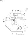
- FIG. 1 is a schematic side view illustrating a configuration of a manufacturing apparatus for a ball bearing according to an embodiment of the present invention.
- FIG. 2 is a schematic side view illustrating an operation of the manufacturing apparatus for a ball bearing shown in FIG. 1 .
- a manufacturing apparatus 100 for a ball bearing includes a ball arranging unit 15 provided on a base 13 via a rotation shaft 14.
- the ball arranging unit 15 includes a workpiece holding table 17, an inner ring moving mechanism 18, a ball inserting mechanism 19, an inclining operation mechanism 21, a flow stopping mechanism 23, and a ball separating member 25.
- the ball placement unit 15 is rotated by the inclining operation mechanism 21 between a horizontal state in which the workpiece holding table 17 provided on an upper portion of the ball placement unit 15 is horizontally arranged (state in FIG. 1 ), and an inclined state in which the workpiece holding table 17 is inclined at an inclination angle ⁇ with respect to the horizontal plane (state in FIG. 2 ).
- the workpiece holding table 17 holds a workpiece W at the upper portion of the ball placement unit 15.
- the workpiece holding table 17 includes a holding portion 41.
- the workpiece W is fitted into the holding portion 41 from an upper side.
- the workpiece holding table 17 is provided with a lock member 43 that moves in a direction toward and away from the holding portion 41.
- the workpiece W is pressed by the lock member 43 in a state of being fitted in the holding portion 41, so as to be fixed to the workpiece holding table 17.
- the workpiece W includes an inner ring 1, an outer ring 3, and a plurality of (thirteen in the illustrated example) balls 7 which are examples of rolling elements.
- the plurality of balls 7 are arranged at equal intervals in a circumferential direction in an annular space 5 between the inner ring 1 and the outer ring 3.
- the balls 7 are held by a cage (not shown). That is, the workpiece W is a ball bearing 9.
- the manufacturing apparatus 100 for a ball bearing is configured such that the plurality of balls 7 are inserted in the annular space 5 between the inner ring 1 and the outer ring 3, and the plurality of balls 7 are arranged at equal intervals in the circumferential direction.
- the inner ring moving mechanism 18 has an inner ring support shaft 39.
- the inner ring support shaft 39 is inserted from a lower side into the inner ring 1 of the workpiece W held by the holding portion 41 of the workpiece holding table 17.
- the inner ring support shaft 39 is inclined along with an inclining operation of the ball placement unit 15 and is always placed coaxially with an axis of the workpiece W.
- the ball inserting mechanism 19 is supported by a supporting unit 45 provided on an upper surface of the ball placement unit 15.
- the supporting unit 45 includes a column portion 47 standing on the upper surface of the ball placement unit 15, and an arm portion 49 extending from an upper end of the column portion 47 toward the workpiece holding table 17.
- the ball inserting mechanism 19 is supported at a tip end of the arm portion 49.
- the ball inserting mechanism 19 inserts (loads) the plurality of balls 7 into the annular space 5 (see FIG. 3 ) between the inner ring 1 and the outer ring 3 of the workpiece W held by the holding portion 41 of the workpiece holding table 17.
- the flow stopping mechanism 23 is supported by the tip end of the arm portion 49 of the supporting unit 45.
- the flow stopping mechanism 23 includes a flow stopping jig 51 that moves up and down with respect to the workpiece holding table 17. When the flow stopping jig 51 is moved downward, a tip end portion of the flow stopping jig 51 is inserted into the annular space 5 (see FIG. 3 ) between the inner ring 1 and the outer ring 3 of the workpiece W held by the holding portion 41 of the workpiece holding table 17.
- the flow stopping jig 51 is formed in a plate shape that is curved along a circumferential direction of the annular space 5 and narrows toward an insertion direction (a lower side in FIGS. 4A, 4B ) into the annular space 5.
- FIG. 5 is a developed view of the flow stopping jig 51.
- the flow stopping jig 51 has a pair of side edges 55 formed in a straight line in a state of being developed in a plane.
- the pair of side edges 55 of the flow stopping jig 51 has a curved shape that bulges outward in a state of being curved along the annular space 5.
- a length in the circumferential direction at a base portion of the flow stopping jig 51 is slightly smaller than a length in the circumferential direction of a space formed when the balls 7 inserted in the annular space 5 are collected in one region.
- FIG. 6 is a perspective view of the ball separating member 25.
- the ball separating member 25 has a base portion 61 formed in an annular shape, and a plurality of working arrows 63 having different lengths.
- the working arrows 63 stand on the base portion 61 and arranged at equal intervals in the circumferential direction.
- the ball separating member 25 includes the same number of working arrows 63 as the number of balls 7 (thirteen in the present embodiment).
- One of the working arrows 63 is a reference working arrow 63A, and other working arrows 63 are arranged at symmetrical positions on both sides of the reference working arrow 63A in the circumferential direction.
- the reference working arrow 63A is shorter than the working arrows 63 on both sides.
- the axial lengths of the working arrows 63 arranged at symmetrical positions on both sides of the reference working arrow 63A in the circumferential direction gradually increases as the working arrows 63 are farther from the reference working arrow 63A.
- a tip end portion of the reference working arrow 63A has a planar shape. Tip end portions of the working arrows 63 other than the reference working arrow 63A form an inclined surface extending toward a tip end side as the working arrows 63 are farther from the reference working arrow 63A in the circumferential direction.
- the working arrows 63 arranged at symmetrical positions on both sides of the reference working arrow 63A in the circumferential direction have the same shape as each other, but may not necessarily have the same shape.
- FIG. 7 is a perspective view for illustrating the arrangement of the flow stopping jig 51 and the ball separating member 25 with respect to the workpiece W.
- the flow stopping jig 51 of the flow stopping mechanism 23 (see FIG. 1 and FIG. 2 ) and the ball separating member 25 are arranged above and below the workpiece W which is held by the holding portion 41 of the workpiece holding table 17.
- the flow stopping jig 51 is arranged above the workpiece W
- the ball separating member 25 is arranged below the workpiece W.
- the reference working arrow 63A of the ball separating member 25 is arranged on a lower side of the inclination of the workpiece W.
- the ball separating member 25 may be arranged above the workpiece W
- the flow stopping jig 51 may be arranged below the workpiece W.
- the workpiece W is conveyed to the ball placement unit 15 in a horizontal state and held by the holding portion 41 of the workpiece holding table 17 (step S1).
- the inner ring support shaft 39 is inserted into and supported by an inner periphery of the inner ring 1, and the outer ring 3 is fixed to the holding portion 41 by the lock member 43.
- the ball placement unit 15 is inclined by the inclining operation mechanism 21 to the inclined state where the workpiece holding table 17 is inclined at the inclination angle ⁇ with respect to the horizontal plane (step S2).
- the inner ring support shaft 39 of the inner ring moving mechanism 18 is inclined along with the inclining operation of the ball placement unit 15.
- a center axis of the inner ring support shaft 39 of the inner ring moving mechanism 18 is arranged at a position displaced to a lower side (left side in FIG. 2 ) of the inclination in a plane perpendicular to a center axis of the workpiece W. Accordingly, the center of the inner ring 1 is decentered to the lower side of the inclination with respect to the center of the outer ring 3. Therefore, the annular space 5 between the inner ring 1 and the outer ring 3 is narrower at the lower side of the inclination and is wider at an upper side of the inclination.
- FIGS. 9A and 9B are views for illustrating a ball inserting step.
- a ball 7 is inserted into the annular space 5 between the inner ring 1 and the outer ring 3 held by the workpiece holding table 17 (see FIG. 1 and FIG. 2 ) from the ball inserting mechanism 19 (step S3).
- the annular space 5 is enlarged at the upper side of the inclination, so that the balls 7 can be easily and smoothly inserted into the annular space 5 by the ball inserting mechanism 19.
- the balls 7 move to the left and right without staying at an inserted position due to its own weight. Therefore, the balls 7 that are already inserted do not get in the way when inserting other balls 7.
- FIG. 9A a ball 7 is inserted into the annular space 5 between the inner ring 1 and the outer ring 3 held by the workpiece holding table 17 (see FIG. 1 and FIG. 2 ) from the ball inserting mechanism 19 (step S3).
- the annular space 5 is enlarged at the upper side of the inclination, so that the balls 7 can be easily and smoothly inserted into the annular space 5 by the ball inserting mechanism 19.
- the balls 7 inserted in the annular space 5 are placed in a state of being collected in the enlarged region on the upper side of the inclination. That is, the balls 7 inserted in the annular space 5 are placed in a state of being collected in one region along the circumferential direction of the annular space 5.
- the ball placement unit 15 is returned to the horizontal state (the state in FIG. 1 ) in which the workpiece holding table 17 is horizontal by the inclining operation mechanism 21 (step S4).
- the center axis of the inner ring support shaft 39 is moved to a position coaxial with the axis of the workpiece W. Accordingly, the centers of the outer ring 3 and the inner ring 1 coincide with each other, and the annular space 5 has an equal gap over the circumferential direction.
- FIG. 11 is a perspective view of the workpiece W and the flow stopping jig 51 for illustrating a flow stopping step.
- the flow stopping jig 51 of the flow stopping mechanism 23 is inserted along an axial direction of the inner ring 1 and the outer ring 3 from the upper side into the space portion without the ball 7 in the annular space 5 of the workpiece W (step S5).
- the balls 7 collected in the one region can roll and move to the space portion without the ball 7.
- the flow stopping jig 51 into the annular space 5
- the movement of the loaded balls 7 can be restricted, and the balls 7 can be held within the one region.
- the operation of inserting the flow stopping jig 51 into the annular space 5 is performed at the same time with the horizontal operation in which the ball placement unit 15 is returned horizontally and the inner ring 1 is moved to align the centers of the outer ring 3 and the inner ring 1.
- the operation of inserting may be performed after the ball placement unit 15 is returned horizontally.
- FIG. 12 is a perspective view of the workpiece W, the flow stopping jig 51, and the ball separating member 25 for illustrating a ball separating step.
- the ball separating member 25 is raised with respect to the workpiece W, and the plurality of working arrows 63 are inserted into the annular space 5 while the flow stopping jig 51 is removed from the annular space 5 from a state of being arranged in the annular space 5. Accordingly, the tip ends of the plurality of protruding working arrows 63 corresponding to the number of the balls 7 are sequentially inserted in the axial direction between the plurality of balls 7 placed in the annular space 5, so that the plurality of balls 7 are arranged at equal intervals in the circumferential direction (step S6).
- FIG. 13 is a schematic view illustrating movement of the balls 7 in the ball separating step.
- Raising speeds of the flow stopping jig 51 and the ball separating member 25 are substantially the same. Therefore, when the flow stopping jig 51 and the ball separating member 25 are raised, a relative position between the flow stopping jig 51 and the ball separating member 25 would not change. That is, relative positions of the balls 7 with respect to the flow stopping jig 51 and the ball separating member 25 change.
- positions of the balls 7 at the time of inserting the working arrows 63 of the ball separating member 25 into the annular space 5 while removing the flow stopping jig 51 arranged in the annular space 5 are shown stepwise at height positions H 1 to H 6 .
- the height positions H 1 to H 6 indicate the relative positions of the balls 7 with respect to the flow stopping jig 51 and the ball separating member 25.
- the relative positions of the balls 7 with respect to the flow stopping jig 51 and the ball separating member 25 are in a positional relationship at the height position H 1 . That is, the flow stopping jig 51 is inserted into the space portion of the annular space 5 without the ball 7.
- a ball 7 gets in between two longest working arrows 63 (two working arrows 63 at the left and right ends in FIG. 13 ) as the ball separating member 25 raises. Then, the remaining twelve balls 7 are pushed out toward the flow stopping jig 51 side from the two longest working arrows 63.
- the balls 7 separated to the circumferentially outer side (left and right sides in FIG. 13 ) of the working arrows 63 are not shown in FIG. 13 .
- both the flow stopping jig 51 and the ball separating member 25 raise as shown by an arrow in FIG. 13 .
- the working arrows 63 of the ball separating member 25 get in between respective balls 7 placed in the annular space 5, and the plurality of balls 7 are arranged at equal intervals in the circumferential direction.
- a cage for holding the balls 7 is fitted into the annular space 5, so that the balls 7 are arranged at equal intervals and rollably held in the ball bearing.
- the ball inserting step of inserting a plurality of balls 7 into one region along the circumferential direction of the annular space 5 and the ball separating step of arranging the balls 7 at equal intervals in the circumferential direction by the working arrows 36 are continuously performed. Therefore, it is possible to omit the ball collecting step of collecting the balls 7 inserted into the annular space 5 in the ball inserting step in one place. Further, operations for the ball arranging work in a ball bearing can be reduced to improve the workability. Further, ball rubbing in the ball collecting step can be avoided, so that the risk of a ball scratch can be reduced. In addition, steps from the ball separating step to the ball inserting step are continuously performed, so that the assembling can be easily performed even for a ball bearing without a deformation margin in which the balls are held between the inner ring and the outer ring.
- the inner ring 1 is moved to a side opposite to the one region with respect to the outer ring 3, and the annular space 5 is enlarged radially in one region before the balls 7 are inserted. Therefore, the balls can be smoothly inserted into the annular space 5.
- the flow stopping jig 51 is inserted into the annular space 5 along the axial direction of the inner ring 1 and the outer ring 3. Therefore, the movement of the inserted balls 7 collected in one region can be restricted by the flow stopping jig 51 so as to suppress the spread of the balls 7. Accordingly, the plurality of balls 7 inserted into the annular space 5 can be separated in a state of being held in one place without spreading.
- the inner ring 1 and the outer ring 3 are inclined with respect to the horizontal plane with one region upward. Therefore, the balls 7 inserted in the one region of the annular space 5 are moved downward due to their own weight and arranged in order. Accordingly, the ball inserting step can be smoothly performed.
- the ball inserting step and the ball separating step can be continuously performed without horizontally conveying the inner ring 1 and the outer ring 3. Therefore, the spread of the balls 7 during the horizontal conveyance can be avoided, and the workability can be improved.
- the ball bearing in which balls 7 are arranged at equal intervals in the annular space 5 between the inner ring 1 and the outer ring 3 by using the ball arranging method described above, the ball bearing in which balls 7 are arranged at equal intervals in the circumferential direction in the annular space 5 between the inner ring 1 and the outer ring 3 can be easily manufactured.
- the ball inserting step of inserting the plurality of balls 7 into one region along the circumferential direction of the annular space 5 by the ball loading mechanism 19 and the ball separating step of arranging the balls 7 at equal intervals in the circumferential direction by the working arrows 36 of the ball separating member 25 can be continuously performed. Accordingly, it is possible to omit the ball collecting step of collecting the balls 7 inserted into the annular space 5 in the ball inserting step in one place. Therefore, operations for the ball arranging work in a ball bearing can be reduced to improve the workability. Further, ball rubbing in the ball collecting step can be avoided, so that the risk of a ball scratch can be reduced. In addition, steps from the ball separating step to the ball inserting step are continuously performed, so that the assembling can be easily performed even for a ball bearing without a deformation margin in which the balls are held between the inner ring and the outer ring.
- the inner ring 1 is moved to a side opposite to the one region with respect to the outer ring 3 by the inner ring moving mechanism 18, and the annular space 5 is enlarged radially in the one region, so that the balls can be easily inserted into the annular space 5, and the workability can be further improved.
- a vertical plane with respect to the axial direction of the inner ring 1 and the outer ring 3 held on the workpiece holding table 17 is inclined by the inclining operation mechanism 21, so that the balls 7 inserted in the one region of the annular space 5 are moved downward due to their own weight and arranged in order. Accordingly, the ball inserting step can be smoothly performed by the ball inserting mechanism 19.
- the flow stopping jig 51 is formed in a plate shape that is curved along the circumferential direction of the annular space 5 and narrows toward the insertion direction into the annular space 5. Accordingly, the movement of the balls 7 in the annular space 5 can be well restricted by the flow stopping jig 51.
- the pair of side edges 55 of the flow stopping jig 51 are straight in a state of being developed in a plane and forms a curved shape that bulges outward in a state of being curved along the annular space 5. Therefore, when the flow stopping jig 51 is inserted into or removed from the annular space 5, the pair of side edges 55 with the curved shape that bulges outward is in smooth contact with the balls 7 in the annular space 5, so that a ball scratch due to the contact between the flow stopping jig 51 and the balls 7 can be avoided.
- the manufacturing method for a rolling bearing described above is applicable also to the manufacturing of various machines (including one using manual power) including a rolling bearing.
- the inventive concept of the present invention is also applicable to a linear motion device such as a linear motion guide apparatus including a rail, a slider or the like, a ball screw apparatus or a screw apparatus including a screw shaft, a nut or the like, an apparatus combining a linear motion guide bearing and a ball screw, or an actuator including an XY table or the like.
- inventive concept of the present invention is also applicable to a steering apparatus such as a steering column, a universal joint, an intermediate gear, a rack and pinion, an electric power steering apparatus, a worm reducer, a torque sensor or the like.
- the inventive concept of the present invention can be widely applicable to the above-mentioned machine, vehicles including a steering device, a machine tool, housing equipment or the like.
- a machine, vehicle or the like obtained as described above can be configured at low-cost and with a high-grade structure than those in the related art.
Landscapes
- Engineering & Computer Science (AREA)
- General Engineering & Computer Science (AREA)
- Mechanical Engineering (AREA)
- Mounting Of Bearings Or Others (AREA)
- Automatic Assembly (AREA)
Abstract
Description
- The present invention relates to a ball arranging method for a ball bearing, a manufacturing method and manufacturing apparatus for a ball bearing, and manufacturing methods for a machine and a vehicle.
- As a technique for arranging a plurality of balls at equal intervals between inner and outer rings of a ball bearing, for example, there is a method disclosed in
Patent Document 1. In this method, a plurality of balls placed between inner and outer rings are collected in one region in a circumferential direction, and the collected balls are distributed into three regions in the circumferential direction between the inner and outer rings. Then, a plurality of working arrows are sequentially inserted in an axial direction between each of the plurality of balls distributed to the respective regions, so that the plurality of balls are arranged at equal intervals in the circumferential direction. - Patent Document 1:
JP-A-2008-200789 - In the above ball arranging method, a ball collecting step of collecting the plurality of balls placed between the inner and outer rings in one region in the circumferential direction is additionally performed between a ball inserting step of inserting the balls between the inner and outer rings and a ball separating step of arranging the balls at equal intervals in the circumferential direction. Further, since the ball inserting step, the ball collecting step and the ball separating step are performed at different positions, it is necessary to convey a workpiece to a next step after the ball inserting step. That is, since the above-described ball arranging technique requires a larger number of steps and time for conveyance between the steps, improvement in workability is desired.
- Accordingly, an object of the present invention is to provide a ball arranging method for a ball bearing, a manufacturing method and manufacturing apparatus for a ball bearing, and manufacturing methods for a machine and a vehicle, which can improve workability of ball arranging work of placing and arranging balls between inner and outer rings at equal intervals.
-
- (1) A ball arranging method for a ball bearing includes:
- a ball inserting step of inserting a plurality of balls into one region along a circumferential direction of an annular space formed between an inner ring and an outer ring;
- a flow stopping step of placing a flow stopping jig on a circumferentially outer side of the one region in the annular space so as to hold the inserted plurality of balls within the one region; and
- a ball separating step of sequentially inserting, in an axial direction, tip ends of a plurality of working arrows provided to protrude correspondingly to a number of the balls between the plurality of balls while the flow stopping jig is removed from the annular space from a state of being placed in the annular space, so as to arrange the plurality of balls at equal intervals in the circumferential direction,
- wherein the ball inserting step, the flow stopping step and the ball separating step are performed in this order.
According to this ball arranging method for a ball bearing, the ball inserting step of inserting the plurality of balls into the one region along the circumferential direction of the annular space and the ball separating step of arranging the balls at equal intervals in the circumferential direction by the working arrows are continuously performed, so that a ball collecting step of collecting the balls inserted into the annular space in the ball inserting step in one place can be omitted. Therefore, operations for the ball arranging work in a ball bearing can be reduced to improve the workability. Further, ball rubbing in the ball collecting step can be avoided, so that the risk of a ball scratch can be reduced. In addition, the steps from the ball inserting step to the ball separating step are continuously performed, so that the assembling can be easily performed even for a ball bearing without a deformation margin in which the balls are held between the inner ring and the outer ring. - (2) In the ball arranging method for a ball bearing according to (1), in the ball inserting step, the inner ring is moved to a side opposite to the one region with respect to the outer ring, so that the annular space is enlarged radially in the one region before the balls are inserted.
According to this ball arranging method for a ball bearing, the inner ring is moved to a side opposite to the one region with respect to the outer ring, so that the annular space is enlarged radially in the one region before the balls are inserted. Accordingly, the balls can be smoothly inserted into the annular space. - (3) In the ball arranging method for a ball bearing according to (1) or (2), in the flow stopping step, the flow stopping jig is inserted into the annular space along the axial direction of the inner ring and the outer ring.
According to this ball arranging method for a ball bearing, the movement of the inserted balls collected in the one region can be restricted by the flow stopping jig so as to suppress the spread of the balls. Accordingly, the balls inserted into the annular space can be separated in a state of being held in one place without spreading. - (4) In the ball arranging method for a ball bearing according to any one of (1) to (3), in the ball inserting step, the inner ring and the outer ring are inclined with respect to a horizontal plane with the one region upward.
According to this ball arranging method for a ball bearing, the balls inserted in the one region of the annular space are moved downward due to their own weight and arranged in order. Accordingly, the ball inserting step can be smoothly performed. - (5) In the ball arranging method for a ball bearing according to any one of (1) to (4), steps from the ball inserting step to the ball separating step are continuously performed without horizontally conveying the inner ring and the outer ring.
According to this ball arranging method for a ball bearing, the spread of the balls during the horizontal conveyance can be avoided, and the workability can be improved. - (6) A ball arranging method for a ball bearing includes:
- decentering a center of an inner ring with respect to a center of an outer ring to enlarge one region along a circumferential direction of an annular space formed between the inner ring and the outer ring;
- inclining the outer ring and the inner ring with a side opposite to a side on which the inner ring is decentered upward, and inserting a plurality of balls into the one region of the annular space;
- inserting a flow stopping jig into the annular space to hold the plurality of balls within the one region while returning the outer ring and the inner ring horizontally; and
- inserting a plurality of working arrows provided to protrude correspondingly to a number of the balls, between the plurality of balls while removing the flow stopping jig from the annular space.
According to this ball arranging method for a ball bearing, the ball inserting and the ball separating by the working arrows are continuously performed, so that a ball collecting step of collecting the plurality of balls inserted in the annular space by the ball inserting within one place can be omitted. Therefore, operations for the ball arranging work in a ball bearing can be reduced to improve the workability. Further, ball rubbing in the ball collecting step can be avoided, so that the risk of a ball scratch can be reduced. In addition, steps from the ball inserting to the ball separating are continuously performed, so that the assembling can be easily performed even for a ball bearing without a deformation margin in which the balls are held between the inner ring and the outer ring. - (7) A manufacturing method for a ball bearing in which a plurality of balls are arranged at equal intervals in an annular space between an inner ring and an outer ring uses the ball arranging method according to any one of (1) to (6).
According to this manufacturing method for a ball bearing, a ball bearing in which the balls are arranged at equal intervals in a circumferential direction in the annular space between the inner ring and the outer ring can be easily manufactured. - (8) A manufacturing apparatus for a ball bearing includes:
- a workpiece holding table that is configured to hold an inner ring and an outer ring such that an annular space is formed between the inner ring and the outer ring;
- a ball inserting mechanism that is configured to insert a plurality of balls into one region along a circumferential direction of the annular space formed between the inner ring and the outer ring which are held by the workpiece holding table;
- a flow stopping mechanism that is configured to place a flow stopping jig on a circumferentially outer side of the one region in the annular space so as to hold the plurality of balls which are inserted within the one region; and
- a ball separating member that includes a plurality of working arrows provided to protrude correspondingly to a number of the balls and is configured such that tip ends of the plurality of working arrows are sequentially inserted in an axial direction between the plurality of balls while removing the flow stopping jig from the annular space from a state of being placed in the annular space, so as to arrange the plurality of balls at equal intervals in the circumferential direction.
According to this manufacturing apparatus for a ball bearing, a ball inserting step of inserting the plurality of balls into one region along the circumferential direction of the annular space by the ball inserting mechanism and a ball separating step of arranging the balls at equal intervals in the circumferential direction by the working arrows of the ball separating member can be continuously performed. Accordingly, it is possible to omit the ball collecting step of collecting the balls inserted into the annular space in the ball inserting step in one place. Therefore, operations for the ball arranging work in a ball bearing can be reduced to improve the workability. Further, ball rubbing in the ball collecting step can be avoided, so that the risk of a ball scratch can be reduced. In addition, steps from the ball inserting to the ball separating are continuously performed, so that the assembling can also be easily performed for a ball bearing without a deformation margin in which the balls are held between the inner ring and the outer ring. - (9) The manufacturing apparatus for a ball bearing according to (8), further includes: an inner ring moving mechanism that is configured to move the inner ring to a side opposite to the one region with respect to the outer ring so as to enlarge the annular space radially in the one region.
According to this manufacturing apparatus for a ball bearing, the one region of the annular space is enlarged radially, so that the balls can be easily inserted into the annular space, and the workability can be further improved. - (10) The manufacturing apparatus for a ball bearing according to (8) or (9), further includes: an inclining operation mechanism that is configured to incline a vertical plane with respect to an axial direction of the inner ring and the outer ring held on the workpiece holding table.
According to this manufacturing apparatus for a ball bearing, the balls inserted in the one region of the annular space are moved downward due to their own weight and arranged in order. Accordingly, the ball inserting work can be smoothly performed by the ball inserting mechanism. - (11) In the manufacturing apparatus for a ball bearing according to any one of (8) or (10), the flow stopping jig is formed in a plate shape that is curved along the circumferential direction of the annular space and narrows toward an insertion direction into the annular space.
According to this manufacturing apparatus for a ball bearing, the movement of the balls in the annular space can be well restricted by the flow stopping jig formed in a plate shape that is curved along the circumferential direction of the annular space and narrows toward the insertion direction into the annular space. - (12) In the manufacturing apparatus for a ball bearing according to (11), the flow stopping jig includes a pair of side edges, and the pair of side edges are straight in a state of being developed in a plane and forms a curved shape that bulges outward in a state of being curved along the annular space.
According to this manufacturing apparatus for a ball bearing, when the flow stopping jig is inserted into or removed from the annular space, the side edges with the curved shape that bulges outward is in smooth contact with the balls in the annular space, so that a ball scratch due to the contact between the flow stopping jig and the balls can be avoided. - (13) A manufacturing apparatus for a ball bearing includes:
- a workpiece holding table that is configured to hold an inner ring and an outer ring such that an annular space is formed between the inner ring and the outer ring;
- an inner ring moving mechanism that is configured to move the inner ring with respect to the outer ring held on the workpiece holding table so as to form one region radially enlarged in the annular space;
- an inclining operation mechanism that is configured to incline a vertical plane with respect to an axial direction of the inner ring and the outer ring held on the workpiece holding table;
- a ball inserting mechanism that is configured to insert a plurality of balls into the one region along a circumferential direction of the annular space;
- a flow stopping mechanism that is configured to place a flow stopping jig on a circumferentially outer side of the one region in the annular space so as to hold the plurality of balls which are inserted within the one region; and
- a ball separating member that includes a plurality of working arrows provided to protrude correspondingly to a number of the balls and is configured such that tip ends of the plurality of working arrows are sequentially inserted in an axial direction between the plurality of balls while removing the flow stopping jig from the annular space from a state of being placed in the annular space, so as to arrange the plurality of balls at equal intervals in the circumferential direction.
According to this manufacturing apparatus for a ball bearing, a ball inserting step of inserting the plurality of balls into one region along the circumferential direction of the annular space by the ball inserting mechanism and a ball separating step of arranging the balls at equal intervals in the circumferential direction by the working arrows of the ball separating member can be continuously performed. Accordingly, it is possible to omit the ball collecting step of collecting the balls fed into the annular space in the ball inserting step in one place. Therefore, operations for the ball arranging work in a ball bearing can be reduced to improve the workability. Further, ball rubbing in the ball collecting step can be avoided, so that the risk of a ball scratch can be reduced. In addition, steps from the ball inserting to the ball separating is continuously performed, so that the assembling can also be easily performed even for a ball bearing without a deformation margin in which the balls are held between the inner ring and the outer ring.
Further, the one region of the annular space may enlarged radially by the inner ring moving mechanism, so that the balls can be easily inserted into the annular space, and the workability can be further improved.
Further, the vertical plane with respect to the axial direction of the inner ring and the outer ring held on the workpiece holding table may be inclined by the inclining operation mechanism, so that the balls inserted in the one region of the annular space are moved downward due to their own weight and arranged in order. Accordingly, the ball inserting step can be smoothly performed by the ball inserting mechanism. - (14) A method for manufacturing a machine uses the manufacturing method for a ball bearing according to (7).
According to this method for manufacturing a machine, it is possible to easily manufacture a machine that uses a ball bearing in which balls are arranged at equal intervals in a circumferential direction in an annular space between an inner ring and an outer ring. - (15) A method for manufacturing a vehicle uses the manufacturing method for a ball bearing according to (7).
- According to this method for manufacturing a vehicle, it is possible to easily manufacture a vehicle that uses a ball bearing in which balls are arranged at equal intervals in a circumferential direction in an annular space between an inner ring and an outer ring.
- According to the present invention, it is possible to improve the workability of the ball arranging work of placing and arranging the balls between the inner and outer rings at equal intervals.
-
-
FIG. 1 is a schematic side view illustrating a configuration of a manufacturing apparatus for a ball bearing according to an embodiment of the present invention. -
FIG. 2 is a schematic side view illustrating an operation of the manufacturing apparatus for a ball bearing shown inFIG. 1 . -
FIG. 3 is a perspective view of a workpiece that is a ball bearing. -
FIGS. 4A to 4D are views illustrating a flow stopping jig, whereinFIG. 4A is a front view,FIG. 4B is a side view,FIG. 4C is a bottom view, andFIG. 4D is a top view. -
FIG. 5 is a developed view of the flow stopping jig. -
FIG. 6 is a perspective view of a ball separating portion. -
FIG. 7 is a perspective view for illustrating the arrangement of the flow stopping jig and the ball separating portion with respect to the workpiece. -
FIG. 8 is a flow chart for illustrating a ball arranging work. -
FIGS. 9A and 9B are views for illustrating a ball inserting step, whereinFIG. 9A is a perspective view of the workpiece before balls are inserted, andFIG. 9B is a perspective view of the workpiece after the balls are inserted. -
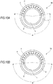
FIGS. 10A and 10B are views illustrating placed states of balls in an annular space, whereinFIG. 10A is a plan view of the workpiece without a deformation margin in which the balls are held between the inner ring and the outer ring, andFIG. 10B is a plan view of the workpiece with a deformation margin in which the balls are held between the inner ring and the outer ring. -
FIG. 11 is a perspective view of the workpiece and the flow stopping jig for illustrating a flow stopping step. -
FIG. 12 is a perspective view of the workpiece, the flow stopping jig, and the ball separating portion for illustrating a ball separating step. -
FIG. 13 is a schematic view illustrating movement of the balls in the ball separating step. -
FIG. 14 is a schematic view illustrating a state in which the balls are arranged by the ball separating step. - Hereinafter, embodiments of the present invention will be described in detail with reference to the drawings.
-
FIG. 1 is a schematic side view illustrating a configuration of a manufacturing apparatus for a ball bearing according to an embodiment of the present invention.FIG. 2 is a schematic side view illustrating an operation of the manufacturing apparatus for a ball bearing shown inFIG. 1 . - A
manufacturing apparatus 100 for a ball bearing according to the present embodiment includes aball arranging unit 15 provided on abase 13 via arotation shaft 14. Theball arranging unit 15 includes a workpiece holding table 17, an innerring moving mechanism 18, aball inserting mechanism 19, aninclining operation mechanism 21, aflow stopping mechanism 23, and aball separating member 25. - The
ball placement unit 15 is rotated by the incliningoperation mechanism 21 between a horizontal state in which the workpiece holding table 17 provided on an upper portion of theball placement unit 15 is horizontally arranged (state inFIG. 1 ), and an inclined state in which the workpiece holding table 17 is inclined at an inclination angle θ with respect to the horizontal plane (state inFIG. 2 ). - The workpiece holding table 17 holds a workpiece W at the upper portion of the
ball placement unit 15. The workpiece holding table 17 includes a holdingportion 41. The workpiece W is fitted into the holdingportion 41 from an upper side. The workpiece holding table 17 is provided with alock member 43 that moves in a direction toward and away from the holdingportion 41. The workpiece W is pressed by thelock member 43 in a state of being fitted in the holdingportion 41, so as to be fixed to the workpiece holding table 17. - As shown in
FIG. 3 , the workpiece W includes aninner ring 1, anouter ring 3, and a plurality of (thirteen in the illustrated example)balls 7 which are examples of rolling elements. The plurality ofballs 7 are arranged at equal intervals in a circumferential direction in anannular space 5 between theinner ring 1 and theouter ring 3. Theballs 7 are held by a cage (not shown). That is, the workpiece W is aball bearing 9. Themanufacturing apparatus 100 for a ball bearing is configured such that the plurality ofballs 7 are inserted in theannular space 5 between theinner ring 1 and theouter ring 3, and the plurality ofballs 7 are arranged at equal intervals in the circumferential direction. - As shown in
FIGS. 1 and2 , the innerring moving mechanism 18 has an innerring support shaft 39. The innerring support shaft 39 is inserted from a lower side into theinner ring 1 of the workpiece W held by the holdingportion 41 of the workpiece holding table 17. The innerring support shaft 39 is inclined along with an inclining operation of theball placement unit 15 and is always placed coaxially with an axis of the workpiece W. - The
ball inserting mechanism 19 is supported by a supportingunit 45 provided on an upper surface of theball placement unit 15. The supportingunit 45 includes acolumn portion 47 standing on the upper surface of theball placement unit 15, and anarm portion 49 extending from an upper end of thecolumn portion 47 toward the workpiece holding table 17. Theball inserting mechanism 19 is supported at a tip end of thearm portion 49. Theball inserting mechanism 19 inserts (loads) the plurality ofballs 7 into the annular space 5 (seeFIG. 3 ) between theinner ring 1 and theouter ring 3 of the workpiece W held by the holdingportion 41 of the workpiece holding table 17. - The
flow stopping mechanism 23 is supported by the tip end of thearm portion 49 of the supportingunit 45. Theflow stopping mechanism 23 includes aflow stopping jig 51 that moves up and down with respect to the workpiece holding table 17. When theflow stopping jig 51 is moved downward, a tip end portion of theflow stopping jig 51 is inserted into the annular space 5 (seeFIG. 3 ) between theinner ring 1 and theouter ring 3 of the workpiece W held by the holdingportion 41 of the workpiece holding table 17. - As shown in
FIGS. 4A to 4D , theflow stopping jig 51 is formed in a plate shape that is curved along a circumferential direction of theannular space 5 and narrows toward an insertion direction (a lower side inFIGS. 4A, 4B ) into theannular space 5. -
FIG. 5 is a developed view of theflow stopping jig 51. - The
flow stopping jig 51 has a pair of side edges 55 formed in a straight line in a state of being developed in a plane. The pair of side edges 55 of theflow stopping jig 51 has a curved shape that bulges outward in a state of being curved along theannular space 5. As shown inFIG. 4C , a length in the circumferential direction at a base portion of theflow stopping jig 51 is slightly smaller than a length in the circumferential direction of a space formed when theballs 7 inserted in theannular space 5 are collected in one region. -
FIG. 6 is a perspective view of theball separating member 25. - The
ball separating member 25 has abase portion 61 formed in an annular shape, and a plurality of workingarrows 63 having different lengths. The workingarrows 63 stand on thebase portion 61 and arranged at equal intervals in the circumferential direction. Theball separating member 25 includes the same number of workingarrows 63 as the number of balls 7 (thirteen in the present embodiment). One of the workingarrows 63 is a reference working arrow 63A, and other workingarrows 63 are arranged at symmetrical positions on both sides of the reference working arrow 63A in the circumferential direction. The reference working arrow 63A is shorter than the workingarrows 63 on both sides. The axial lengths of the workingarrows 63 arranged at symmetrical positions on both sides of the reference working arrow 63A in the circumferential direction gradually increases as the workingarrows 63 are farther from the reference working arrow 63A. - A tip end portion of the reference working arrow 63A has a planar shape. Tip end portions of the working
arrows 63 other than the reference working arrow 63A form an inclined surface extending toward a tip end side as the workingarrows 63 are farther from the reference working arrow 63A in the circumferential direction. - The working
arrows 63 arranged at symmetrical positions on both sides of the reference working arrow 63A in the circumferential direction have the same shape as each other, but may not necessarily have the same shape. -
FIG. 7 is a perspective view for illustrating the arrangement of theflow stopping jig 51 and theball separating member 25 with respect to the workpiece W. - The
flow stopping jig 51 of the flow stopping mechanism 23 (seeFIG. 1 andFIG. 2 ) and theball separating member 25 are arranged above and below the workpiece W which is held by the holdingportion 41 of the workpiece holding table 17. In the example shown inFIG. 1 andFIG. 2 , theflow stopping jig 51 is arranged above the workpiece W, and theball separating member 25 is arranged below the workpiece W. In the inclined state (the state inFIG. 2 ) where the workpiece holding table 17 is inclined by the incliningoperation mechanism 21, the reference working arrow 63A of theball separating member 25 is arranged on a lower side of the inclination of the workpiece W. Incidentally, theball separating member 25 may be arranged above the workpiece W, and theflow stopping jig 51 may be arranged below the workpiece W. - Next, a case of manufacturing a ball bearing by the
manufacturing apparatus 100 for a ball bearing while inserting balls into the workpiece W will be described step by step according to the flowchart shown inFIG. 8 . - The workpiece W is conveyed to the
ball placement unit 15 in a horizontal state and held by the holdingportion 41 of the workpiece holding table 17 (step S1). At this time, the innerring support shaft 39 is inserted into and supported by an inner periphery of theinner ring 1, and theouter ring 3 is fixed to the holdingportion 41 by thelock member 43. - The
ball placement unit 15 is inclined by the incliningoperation mechanism 21 to the inclined state where the workpiece holding table 17 is inclined at the inclination angle θ with respect to the horizontal plane (step S2). At this time, the innerring support shaft 39 of the innerring moving mechanism 18 is inclined along with the inclining operation of theball placement unit 15. Further, a center axis of the innerring support shaft 39 of the innerring moving mechanism 18 is arranged at a position displaced to a lower side (left side inFIG. 2 ) of the inclination in a plane perpendicular to a center axis of the workpiece W. Accordingly, the center of theinner ring 1 is decentered to the lower side of the inclination with respect to the center of theouter ring 3. Therefore, theannular space 5 between theinner ring 1 and theouter ring 3 is narrower at the lower side of the inclination and is wider at an upper side of the inclination. -
FIGS. 9A and 9B are views for illustrating a ball inserting step. - As shown in
FIG. 9A , aball 7 is inserted into theannular space 5 between theinner ring 1 and theouter ring 3 held by the workpiece holding table 17 (seeFIG. 1 andFIG. 2 ) from the ball inserting mechanism 19 (step S3). At this time, theannular space 5 is enlarged at the upper side of the inclination, so that theballs 7 can be easily and smoothly inserted into theannular space 5 by theball inserting mechanism 19. Further, theballs 7 move to the left and right without staying at an inserted position due to its own weight. Therefore, theballs 7 that are already inserted do not get in the way when insertingother balls 7. As shown inFIG. 9B , theballs 7 inserted in theannular space 5 are placed in a state of being collected in the enlarged region on the upper side of the inclination. That is, theballs 7 inserted in theannular space 5 are placed in a state of being collected in one region along the circumferential direction of theannular space 5. - The
ball placement unit 15 is returned to the horizontal state (the state inFIG. 1 ) in which the workpiece holding table 17 is horizontal by the inclining operation mechanism 21 (step S4). At this time, the center axis of the innerring support shaft 39 is moved to a position coaxial with the axis of the workpiece W. Accordingly, the centers of theouter ring 3 and theinner ring 1 coincide with each other, and theannular space 5 has an equal gap over the circumferential direction. - Then, as shown in
FIG. 10A , in theannular space 5, theballs 7 are collected in one region, and a circumferentially outer side of the one area becomes a space portion which is not provided with theballs 7. In a workpiece without a deformation margin in which theballs 7 are held between theinner ring 1 and theouter ring 3, a region α of the space portion is in a range of 180° or larger. As shown inFIG. 10B , in a workpiece W with a deformation margin in which theballs 7 are held in grooves of theinner ring 1 and theouter ring 3, a region α of the space portion without theball 7 on the circumferentially outer side of the one region is in a range of less than 180°. -
FIG. 11 is a perspective view of the workpiece W and theflow stopping jig 51 for illustrating a flow stopping step. - The
flow stopping jig 51 of theflow stopping mechanism 23 is inserted along an axial direction of theinner ring 1 and theouter ring 3 from the upper side into the space portion without theball 7 in theannular space 5 of the workpiece W (step S5). Here, when the centers of theouter ring 3 and theinner ring 1 are made to coincide with each other, theballs 7 collected in the one region can roll and move to the space portion without theball 7. However, by inserting and placing theflow stopping jig 51 into theannular space 5, the movement of the loadedballs 7 can be restricted, and theballs 7 can be held within the one region. The operation of inserting theflow stopping jig 51 into theannular space 5 is performed at the same time with the horizontal operation in which theball placement unit 15 is returned horizontally and theinner ring 1 is moved to align the centers of theouter ring 3 and theinner ring 1. Alternatively, the operation of inserting may be performed after theball placement unit 15 is returned horizontally. -
FIG. 12 is a perspective view of the workpiece W, theflow stopping jig 51, and theball separating member 25 for illustrating a ball separating step. - The
ball separating member 25 is raised with respect to the workpiece W, and the plurality of workingarrows 63 are inserted into theannular space 5 while theflow stopping jig 51 is removed from theannular space 5 from a state of being arranged in theannular space 5. Accordingly, the tip ends of the plurality of protruding workingarrows 63 corresponding to the number of theballs 7 are sequentially inserted in the axial direction between the plurality ofballs 7 placed in theannular space 5, so that the plurality ofballs 7 are arranged at equal intervals in the circumferential direction (step S6). -
FIG. 13 is a schematic view illustrating movement of theballs 7 in the ball separating step. - Raising speeds of the
flow stopping jig 51 and theball separating member 25 are substantially the same. Therefore, when theflow stopping jig 51 and theball separating member 25 are raised, a relative position between theflow stopping jig 51 and theball separating member 25 would not change. That is, relative positions of theballs 7 with respect to theflow stopping jig 51 and theball separating member 25 change. - In the example shown in
FIG. 13 , positions of theballs 7 at the time of inserting the workingarrows 63 of theball separating member 25 into theannular space 5 while removing theflow stopping jig 51 arranged in theannular space 5 are shown stepwise at height positions H1 to H6. The height positions H1 to H6 indicate the relative positions of theballs 7 with respect to theflow stopping jig 51 and theball separating member 25. - At the start of the ball separating step, the relative positions of the
balls 7 with respect to theflow stopping jig 51 and theball separating member 25 are in a positional relationship at the height position H1. That is, theflow stopping jig 51 is inserted into the space portion of theannular space 5 without theball 7. - When the relative positions of the
balls 7 with respect to theflow stopping jig 51 and theball separating member 25 is the height position H1, a ball 7 (the seventh ball located at the circumferential center among the thirteen balls inFIG. 10A ) gets in between two longest working arrows 63 (two workingarrows 63 at the left and right ends inFIG. 13 ) as theball separating member 25 raises. Then, the remaining twelveballs 7 are pushed out toward theflow stopping jig 51 side from the two longest workingarrows 63. - Among the plurality of
balls 7 at the height positions H1 to H6, theballs 7 separated to the circumferentially outer side (left and right sides inFIG. 13 ) of the workingarrows 63 are not shown inFIG. 13 . - From this state, both the
flow stopping jig 51 and theball separating member 25 raise as shown by an arrow inFIG. 13 . - When the relative positions of the
balls 7 with respect to theflow stopping jig 51 and theball separating member 25 change from the height position H1 to H2, as theball separating member 25 raises, two second longest working arrows 63 (two second workingarrows 63 counting from the left and right ends respectively inFIG. 13 ) get in between theballs 7 at both ends of the height position H1 inFIG. 13 , and the remaining tenballs 7 are pushed out to theflow stopping jig 51 side. - When the relative positions of the
balls 7 with respect to theflow stopping jig 51 and theball separating member 25 change from the height position H2 to H3, two third longest working arrows 63 (two third workingarrows 63 counting from the left and right ends respectively inFIG. 13 ) get in between theballs 7, and the remaining eightballs 7 are pushed out to theflow stopping jig 51 side. - When the relative positions of the
balls 7 with respect to theflow stopping jig 51 and theball separating member 25 change from the height position H3 to H4, two fourth longest working arrows 63 (two fourth workingarrows 63 counting from the left and right ends respectively inFIG. 13 ) get in between theballs 7, and the remaining sixballs 7 are pushed out to theflow stopping jig 51 side. - When the relative positions of the
balls 7 with respect to theflow stopping jig 51 and theball separating member 25 change from the height position H4 to H5, two fifth longest working arrows 63 (two fifth workingarrows 63 counting from the left and right ends respectively inFIG. 13 ) get in between theballs 7, and the remaining fourballs 7 are pushed out to theflow stopping jig 51 side. - At the last, when the relative positions of the
balls 7 with respect to theflow stopping jig 51 and theball separating member 25 change from the height position H5 to H6, two shortest working arrows 63 (two sixth workingarrows 63 counting from the left and right ends respectively inFIG. 13 ) get in between theballs 7, and the remaining twoballs 7 are pushed out to theflow stopping jig 51 side. - At this time, the two
balls 7 in contact with the pair of side edges 55 of theflow stopping jig 51 at the height position H5 are come into contact with the reference working arrow 63A. Then, these twoballs 7 get in between the reference working arrow 63A and the two shortest working arrows 63A. - At the last, as shown in
FIG. 14 , the workingarrows 63 of theball separating member 25 get in betweenrespective balls 7 placed in theannular space 5, and the plurality ofballs 7 are arranged at equal intervals in the circumferential direction. - Thereafter, a cage for holding the
balls 7 is fitted into theannular space 5, so that theballs 7 are arranged at equal intervals and rollably held in the ball bearing. - As described above, according to the ball arranging method for a ball bearing of the present embodiment, the ball inserting step of inserting a plurality of
balls 7 into one region along the circumferential direction of theannular space 5 and the ball separating step of arranging theballs 7 at equal intervals in the circumferential direction by the working arrows 36 are continuously performed. Therefore, it is possible to omit the ball collecting step of collecting theballs 7 inserted into theannular space 5 in the ball inserting step in one place. Further, operations for the ball arranging work in a ball bearing can be reduced to improve the workability. Further, ball rubbing in the ball collecting step can be avoided, so that the risk of a ball scratch can be reduced. In addition, steps from the ball separating step to the ball inserting step are continuously performed, so that the assembling can be easily performed even for a ball bearing without a deformation margin in which the balls are held between the inner ring and the outer ring. - In the ball inserting step, the
inner ring 1 is moved to a side opposite to the one region with respect to theouter ring 3, and theannular space 5 is enlarged radially in one region before theballs 7 are inserted. Therefore, the balls can be smoothly inserted into theannular space 5. - In the flow stopping step, the
flow stopping jig 51 is inserted into theannular space 5 along the axial direction of theinner ring 1 and theouter ring 3. Therefore, the movement of the insertedballs 7 collected in one region can be restricted by theflow stopping jig 51 so as to suppress the spread of theballs 7. Accordingly, the plurality ofballs 7 inserted into theannular space 5 can be separated in a state of being held in one place without spreading. - In the ball loading step, the
inner ring 1 and theouter ring 3 are inclined with respect to the horizontal plane with one region upward. Therefore, theballs 7 inserted in the one region of theannular space 5 are moved downward due to their own weight and arranged in order. Accordingly, the ball inserting step can be smoothly performed. - The ball inserting step and the ball separating step can be continuously performed without horizontally conveying the
inner ring 1 and theouter ring 3. Therefore, the spread of theballs 7 during the horizontal conveyance can be avoided, and the workability can be improved. - According to the manufacturing method for a ball bearing in which the
balls 7 are arranged at equal intervals in theannular space 5 between theinner ring 1 and theouter ring 3 by using the ball arranging method described above, the ball bearing in whichballs 7 are arranged at equal intervals in the circumferential direction in theannular space 5 between theinner ring 1 and theouter ring 3 can be easily manufactured. - According to the
manufacturing apparatus 100 for a ball bearing of the present embodiment, the ball inserting step of inserting the plurality ofballs 7 into one region along the circumferential direction of theannular space 5 by theball loading mechanism 19 and the ball separating step of arranging theballs 7 at equal intervals in the circumferential direction by the working arrows 36 of theball separating member 25 can be continuously performed. Accordingly, it is possible to omit the ball collecting step of collecting theballs 7 inserted into theannular space 5 in the ball inserting step in one place. Therefore, operations for the ball arranging work in a ball bearing can be reduced to improve the workability. Further, ball rubbing in the ball collecting step can be avoided, so that the risk of a ball scratch can be reduced. In addition, steps from the ball separating step to the ball inserting step are continuously performed, so that the assembling can be easily performed even for a ball bearing without a deformation margin in which the balls are held between the inner ring and the outer ring. - The
inner ring 1 is moved to a side opposite to the one region with respect to theouter ring 3 by the innerring moving mechanism 18, and theannular space 5 is enlarged radially in the one region, so that the balls can be easily inserted into theannular space 5, and the workability can be further improved. - A vertical plane with respect to the axial direction of the
inner ring 1 and theouter ring 3 held on the workpiece holding table 17 is inclined by the incliningoperation mechanism 21, so that theballs 7 inserted in the one region of theannular space 5 are moved downward due to their own weight and arranged in order. Accordingly, the ball inserting step can be smoothly performed by theball inserting mechanism 19. - The
flow stopping jig 51 is formed in a plate shape that is curved along the circumferential direction of theannular space 5 and narrows toward the insertion direction into theannular space 5. Accordingly, the movement of theballs 7 in theannular space 5 can be well restricted by theflow stopping jig 51. - The pair of side edges 55 of the
flow stopping jig 51 are straight in a state of being developed in a plane and forms a curved shape that bulges outward in a state of being curved along theannular space 5. Therefore, when theflow stopping jig 51 is inserted into or removed from theannular space 5, the pair of side edges 55 with the curved shape that bulges outward is in smooth contact with theballs 7 in theannular space 5, so that a ball scratch due to the contact between theflow stopping jig 51 and theballs 7 can be avoided. - The present invention is not limited to the above-mentioned embodiment, but modifications and applications made by one skilled in the art based on mutual combination of the configurations of the embodiments, description in the specification, and well-known art, is also within the scope and protection of the present invention.
- The manufacturing method for a rolling bearing described above is applicable also to the manufacturing of various machines (including one using manual power) including a rolling bearing. For example, the inventive concept of the present invention is also applicable to a linear motion device such as a linear motion guide apparatus including a rail, a slider or the like, a ball screw apparatus or a screw apparatus including a screw shaft, a nut or the like, an apparatus combining a linear motion guide bearing and a ball screw, or an actuator including an XY table or the like.
- Further, the inventive concept of the present invention is also applicable to a steering apparatus such as a steering column, a universal joint, an intermediate gear, a rack and pinion, an electric power steering apparatus, a worm reducer, a torque sensor or the like.
- The inventive concept of the present invention can be widely applicable to the above-mentioned machine, vehicles including a steering device, a machine tool, housing equipment or the like.
- A machine, vehicle or the like obtained as described above can be configured at low-cost and with a high-grade structure than those in the related art.
- This application is based on Japanese Patent Application No.
2018-103734 filed on May 30, 2018 -
- 1
- inner ring
- 3
- outer ring
- 5
- annular space
- 7
- ball
- 9
- ball bearing
- 17
- workpiece holding table
- 18
- inner ring moving mechanism
- 19
- ball inserting mechanism
- 21
- inclining operation mechanism
- 23
- flow stopping mechanism
- 25
- ball separating member
- 51
- flow stopping jig
- 55
- side edge
- 63
- working arrow
- 100
- manufacturing apparatus for ball bearing
Claims (15)
- A ball arranging method for a ball bearing, comprising:a ball inserting step of inserting a plurality of balls into one region along a circumferential direction of an annular space formed between an inner ring and an outer ring;a flow stopping step of placing a flow stopping jig on a circumferentially outer side of the one region in the annular space so as to hold the inserted plurality of balls within the one region; anda ball separating step of sequentially inserting, in an axial direction, tip ends of a plurality of working arrows provided to protrude correspondingly to a number of the balls between the plurality of balls while the flow stopping jig is removed from the annular space from a state of being placed in the annular space, so as to arrange the plurality of balls at equal intervals in the circumferential direction,wherein the ball inserting step, the flow stopping step and the ball separating step are performed in this order.
- The ball arranging method according to claim 1,
wherein in the ball inserting step, the inner ring is moved to a side opposite to the one region with respect to the outer ring, so that the annular space is enlarged radially in the one region before the balls are inserted. - The ball arranging method according to claim 1 or 2,
wherein in the flow stopping step, the flow stopping jig is inserted into the annular space along the axial direction of the inner ring and the outer ring. - The ball arranging method according to any one of claims 1 to 3,
wherein in the ball inserting step, the inner ring and the outer ring are inclined with respect to a horizontal plane with the one region upward. - The ball arranging method according to any one of claims 1 to 4,
wherein steps from the ball inserting step to the ball separating step are continuously performed without horizontally conveying the inner ring and the outer ring. - A ball arranging method for a ball bearing, comprising:decentering a center of an inner ring with respect to a center of an outer ring to enlarge one region along a circumferential direction of an annular space formed between the inner ring and the outer ring;inclining the outer ring and the inner ring with a side opposite to a side on which the inner ring is decentered upward, and inserting a plurality of balls into the one region of the annular space;inserting a flow stopping jig into the annular space to hold the plurality of balls within the one region while returning the outer ring and the inner ring horizontally; andinserting a plurality of working arrows provided to protrude correspondingly to a number of the balls, between the plurality of balls while removing the flow stopping jig from the annular space.
- A manufacturing method for a ball bearing in which a plurality of balls are arranged at equal intervals in an annular space between an inner ring and an outer ring by using the ball arranging method according to any one of claims 1 to 6.
- A manufacturing apparatus for a ball bearing, comprising:a workpiece holding table that is configured to hold an inner ring and an outer ring such that an annular space is formed between the inner ring and the outer ring;a ball inserting mechanism that is configured to insert a plurality of balls into one region along a circumferential direction of the annular space formed between the inner ring and the outer ring which are held by the workpiece holding table;a flow stopping mechanism that is configured to place a flow stopping jig on a circumferentially outer side of the one region in the annular space so as to hold the plurality of balls which are inserted within the one region; anda ball separating member that includes a plurality of working arrows provided to protrude correspondingly to a number of the balls and is configured such that tip ends of the plurality of working arrows are sequentially inserted in an axial direction between the plurality of balls while removing the flow stopping jig from the annular space from a state of being placed in the annular space, so as to arrange the plurality of balls at equal intervals in the circumferential direction.
- The manufacturing apparatus for a ball bearing according to claim 8, further comprising:
an inner ring moving mechanism that is configured to move the inner ring to a side opposite to the one region with respect to the outer ring so as to enlarge the annular space radially in the one region. - The manufacturing apparatus for a ball bearing according to claim 8 or 9, further comprising:
an inclining operation mechanism that is configured to incline a vertical plane with respect to an axial direction of the inner ring and the outer ring held on the workpiece holding table. - The manufacturing apparatus for a ball bearing according to any one of claims 8 to 10,
wherein the flow stopping jig is formed in a plate shape that is curved along the circumferential direction of the annular space and narrows toward an insertion direction into the annular space. - The manufacturing apparatus for a ball bearing according to claim 11,
wherein the flow stopping jig includes a pair of side edges, and the pair of side edges are straight in a state of being developed in a plane and forms a curved shape that bulges outward in a state of being curved along the annular space. - A manufacturing apparatus for a ball bearing, comprising:a workpiece holding table that is configured to hold an inner ring and an outer ring such that an annular space is formed between the inner ring and the outer ring;an inner ring moving mechanism that is configured to move the inner ring with respect to the outer ring held on the workpiece holding table so as to form one region radially enlarged in the annular space;an inclining operation mechanism that is configured to incline a vertical plane with respect to an axial direction of the inner ring and the outer ring held on the workpiece holding table;a ball inserting mechanism that is configured to insert a plurality of balls into the one region along a circumferential direction of the annular space;a flow stopping mechanism that is configured to place a flow stopping jig on a circumferentially outer side of the one region in the annular space so as to hold the plurality of balls which are inserted within the one region; anda ball separating member that includes a plurality of working arrows provided to protrude correspondingly to a number of the balls and is configured such that tip ends of the plurality of working arrows are sequentially inserted in an axial direction between the plurality of balls while removing the flow stopping jig from the annular space from a state of being placed in the annular space, so as to arrange the plurality of balls at equal intervals in the circumferential direction
- A method for manufacturing a machine that uses the manufacturing method for a ball bearing according to claim 7.
- A method for manufacturing a vehicle that uses the manufacturing method for a ball bearing according to claim 7.
Applications Claiming Priority (2)
| Application Number | Priority Date | Filing Date | Title |
|---|---|---|---|
| JP2018103734 | 2018-05-30 | ||
| PCT/JP2018/045540 WO2019230023A1 (en) | 2018-05-30 | 2018-12-11 | Ball arrangement method for ball bearing, ball bearing manufacturing method and manufacturing device, and machine and vehicle manufacturing method |
Publications (3)
| Publication Number | Publication Date |
|---|---|
| EP3674574A1 true EP3674574A1 (en) | 2020-07-01 |
| EP3674574A4 EP3674574A4 (en) | 2020-12-02 |
| EP3674574B1 EP3674574B1 (en) | 2023-05-17 |
Family
ID=68698771
Family Applications (1)
| Application Number | Title | Priority Date | Filing Date |
|---|---|---|---|
| EP18920416.7A Active EP3674574B1 (en) | 2018-05-30 | 2018-12-11 | Ball arrangement method for ball bearing, ball bearing manufacturing method and manufacturing device, and machine and vehicle manufacturing method |
Country Status (4)
| Country | Link |
|---|---|
| EP (1) | EP3674574B1 (en) |
| JP (1) | JP7275907B2 (en) |
| CN (1) | CN112204268B (en) |
| WO (1) | WO2019230023A1 (en) |
Families Citing this family (11)
| Publication number | Priority date | Publication date | Assignee | Title |
|---|---|---|---|---|
| CN112727933A (en) * | 2020-12-30 | 2021-04-30 | 中山市盈科轴承制造有限公司 | Ball distributor assembly for bearing assembly |
| CN113997229B (en) * | 2021-11-09 | 2023-03-28 | 杭州赛奇机械股份有限公司 | New energy automobile bearing steel ball assembly quality |
| CN114603324B (en) * | 2022-02-17 | 2024-02-13 | 玉环美尔伦机械股份有限公司 | Ball auxiliary assembly machine for bearing machining |
| WO2023243148A1 (en) * | 2022-06-17 | 2023-12-21 | 日本精工株式会社 | Ball placement method for ball bearing, ball bearing manufacturing method and manufacturing device, and machine and vehicle manufacturing method |
| US20250341235A1 (en) * | 2022-06-17 | 2025-11-06 | Nsk Ltd. | Ball arrangement method for ball bearing, manufacturing method and manufacturing device for ball bearing, and manufacturing method for machine and vehicle |
| CN115467901B (en) * | 2022-10-15 | 2023-10-03 | 南通市嘉诚机械有限公司 | Assembling equipment for machining turbocharger bearing body |
| WO2024105809A1 (en) * | 2022-11-16 | 2024-05-23 | 株式会社ジェイテクト | Manufacturing method for rolling bearing device |
| CN116576201B (en) * | 2023-06-15 | 2023-09-12 | 山东丰源汽车科技有限公司 | Automatic assembly machine tool for transmission bearing |
| CN119077334B (en) * | 2024-10-11 | 2025-11-21 | 浙江格莱恩生物科技有限公司 | Water stop clamp accessory assembling structure for automatic equipment assembly in medical consumable field |
| KR102906583B1 (en) * | 2025-05-27 | 2025-12-31 | 주식회사 지씨에이 | Ball alignment and separation apparatus for bearing assembly |
| CN120367941A (en) * | 2025-06-20 | 2025-07-25 | 南京杰轩机械设备有限公司 | Assembly bearing and manufacturing process thereof |
Family Cites Families (14)
| Publication number | Priority date | Publication date | Assignee | Title |
|---|---|---|---|---|
| JPS4934209B1 (en) * | 1970-09-10 | 1974-09-12 | ||
| JPS4934209A (en) * | 1972-07-24 | 1974-03-29 | ||
| JPS5880130U (en) * | 1981-11-27 | 1983-05-31 | エヌ・テ−・エヌ東洋ベアリング株式会社 | Ball shifting machine |
| JPS5947525A (en) * | 1982-09-09 | 1984-03-17 | Koyo Seiko Co Ltd | Positioning method of rotor and device thereof |
| JPH02266113A (en) * | 1989-04-06 | 1990-10-30 | Nobuo Takada | Ball distribution |
| JPH09225757A (en) * | 1996-02-26 | 1997-09-02 | Toyota Motor Corp | Ball offset and equal distribution device and bearing assembly device |
| JP4203475B2 (en) * | 2005-01-20 | 2009-01-07 | 有限会社ナカミチ | Ball array device for bearing |
| JP2008200789A (en) * | 2007-02-19 | 2008-09-04 | Nsk Ltd | Ball bearing ball distribution method and ball splitting jig |
| JP5365479B2 (en) * | 2009-11-13 | 2013-12-11 | 日本精工株式会社 | Ball bearing assembly method and assembly apparatus |
| JP6115123B2 (en) * | 2012-12-26 | 2017-04-19 | 日本精工株式会社 | Angular ball bearing assembly apparatus and angular ball bearing assembly method |
| JP2015139846A (en) * | 2014-01-29 | 2015-08-03 | 日本精工株式会社 | Assembling method of ball bearing and assembling device |
| JP2015193048A (en) * | 2014-03-31 | 2015-11-05 | Ntn株式会社 | Assembly apparatus of roller bearing and manufacturing method of roller bearing |
| JP6264241B2 (en) * | 2014-09-12 | 2018-01-31 | 日本精工株式会社 | Ball bearing assembly method and assembly apparatus |
| JP2018103734A (en) | 2016-12-26 | 2018-07-05 | 株式会社ジェイテクト | Steering device |
-
2018
- 2018-12-11 EP EP18920416.7A patent/EP3674574B1/en active Active
- 2018-12-11 CN CN201880094052.6A patent/CN112204268B/en active Active
- 2018-12-11 WO PCT/JP2018/045540 patent/WO2019230023A1/en not_active Ceased
-
2019
- 2019-06-26 JP JP2019118978A patent/JP7275907B2/en active Active
Also Published As
| Publication number | Publication date |
|---|---|
| CN112204268A (en) | 2021-01-08 |
| JP7275907B2 (en) | 2023-05-18 |
| EP3674574A4 (en) | 2020-12-02 |
| EP3674574B1 (en) | 2023-05-17 |
| JP2019209475A (en) | 2019-12-12 |
| WO2019230023A1 (en) | 2019-12-05 |
| CN112204268B (en) | 2023-05-23 |
Similar Documents
| Publication | Publication Date | Title |
|---|---|---|
| EP3674574B1 (en) | Ball arrangement method for ball bearing, ball bearing manufacturing method and manufacturing device, and machine and vehicle manufacturing method | |
| US11255378B2 (en) | Ball arrangement method for ball bearing, ball bearing manufacturing method and manufacturing device, and machine and vehicle manufacturing method | |
| CN101543992B (en) | Multijoint robot and method of taking out differential motion reducer in the multijoint robot | |
| JP6203085B2 (en) | Positioning member, positioning device, and stator manufacturing method | |
| CN104254701B (en) | The assembling device of angular contact ball bearing and the assemble method of angular contact ball bearing | |
| US10276416B2 (en) | Industrial robot | |
| JP6365287B2 (en) | Assembly method and assembly apparatus | |
| CN108367401B (en) | Assembling apparatus and control method thereof | |
| EP3483462A1 (en) | Rolling body uniform arrangement method for rolling bearing, rolling bearing, machine, and vehicle production method | |
| CN108367867B (en) | Tray conveying device | |
| KR101889846B1 (en) | Pallet transport device | |
| KR20120139534A (en) | Transport robot | |
| KR102017097B1 (en) | Pallet conveying device | |
| CN104582879B (en) | Method for turning and truning fixture | |
| JP2008200789A (en) | Ball bearing ball distribution method and ball splitting jig | |
| KR20170053716A (en) | Ball arranging method and device for ball bearing, and ball bearing manufactured by said ball arranging method | |
| CN105834815A (en) | Feed apparatus and machine tool | |
| JP6702648B2 (en) | Assembly equipment pallet guide device | |
| EP4335582A1 (en) | Ball placement method for ball bearing, ball bearing manufacturing method and manufacturing device, and machine and vehicle manufacturing method | |
| JP7404904B2 (en) | Methods for manufacturing rolling bearings, and methods for manufacturing machines and vehicles | |
| WO2023243148A1 (en) | Ball placement method for ball bearing, ball bearing manufacturing method and manufacturing device, and machine and vehicle manufacturing method | |
| KR20170084389A (en) | Robot for transferring substrate | |
| US7220087B2 (en) | Work processing method in machine tool, processing jig for performing the method, and support device for work processing | |
| JP7131289B2 (en) | Work transfer device, work transfer method, rolling bearing transfer method, rolling bearing, machine, and vehicle manufacturing method | |
| JP6483959B2 (en) | Manufacturing method of bearing |
Legal Events
| Date | Code | Title | Description |
|---|---|---|---|
| STAA | Information on the status of an ep patent application or granted ep patent |
Free format text: STATUS: THE INTERNATIONAL PUBLICATION HAS BEEN MADE |
|
| PUAI | Public reference made under article 153(3) epc to a published international application that has entered the european phase |
Free format text: ORIGINAL CODE: 0009012 |
|
| STAA | Information on the status of an ep patent application or granted ep patent |
Free format text: STATUS: REQUEST FOR EXAMINATION WAS MADE |
|
| 17P | Request for examination filed |
Effective date: 20200318 |
|
| AK | Designated contracting states |
Kind code of ref document: A1 Designated state(s): AL AT BE BG CH CY CZ DE DK EE ES FI FR GB GR HR HU IE IS IT LI LT LU LV MC MK MT NL NO PL PT RO RS SE SI SK SM TR |
|
| AX | Request for extension of the european patent |
Extension state: BA ME |
|
| A4 | Supplementary search report drawn up and despatched |
Effective date: 20201102 |
|
| RIC1 | Information provided on ipc code assigned before grant |
Ipc: B23P 21/00 20060101ALI20201027BHEP Ipc: F16C 43/06 20060101AFI20201027BHEP Ipc: B23P 15/00 20060101ALI20201027BHEP Ipc: F16C 19/06 20060101ALI20201027BHEP |
|
| DAV | Request for validation of the european patent (deleted) | ||
| DAX | Request for extension of the european patent (deleted) | ||
| STAA | Information on the status of an ep patent application or granted ep patent |
Free format text: STATUS: EXAMINATION IS IN PROGRESS |
|
| 17Q | First examination report despatched |
Effective date: 20220214 |
|
| REG | Reference to a national code |
Ref country code: DE Ref legal event code: R079 Ref document number: 602018050070 Country of ref document: DE Free format text: PREVIOUS MAIN CLASS: F16C0043060000 Ipc: F16C0019060000 |
|
| RIC1 | Information provided on ipc code assigned before grant |
Ipc: B23P 19/04 20060101ALI20221025BHEP Ipc: F16C 43/06 20060101ALI20221025BHEP Ipc: F16C 19/06 20060101AFI20221025BHEP |
|
| GRAP | Despatch of communication of intention to grant a patent |
Free format text: ORIGINAL CODE: EPIDOSNIGR1 |
|
| STAA | Information on the status of an ep patent application or granted ep patent |
Free format text: STATUS: GRANT OF PATENT IS INTENDED |
|
| INTG | Intention to grant announced |
Effective date: 20221221 |
|
| RIN1 | Information on inventor provided before grant (corrected) |
Inventor name: DOBASHI, KOUHEI Inventor name: SUZUKI, TAKAHIRO |
|
| GRAS | Grant fee paid |
Free format text: ORIGINAL CODE: EPIDOSNIGR3 |
|
| GRAA | (expected) grant |
Free format text: ORIGINAL CODE: 0009210 |
|
| STAA | Information on the status of an ep patent application or granted ep patent |
Free format text: STATUS: THE PATENT HAS BEEN GRANTED |
|
| AK | Designated contracting states |
Kind code of ref document: B1 Designated state(s): AL AT BE BG CH CY CZ DE DK EE ES FI FR GB GR HR HU IE IS IT LI LT LU LV MC MK MT NL NO PL PT RO RS SE SI SK SM TR |
|
| REG | Reference to a national code |
Ref country code: GB Ref legal event code: FG4D |
|
| REG | Reference to a national code |
Ref country code: CH Ref legal event code: EP |
|
| REG | Reference to a national code |
Ref country code: DE Ref legal event code: R096 Ref document number: 602018050070 Country of ref document: DE |
|
| REG | Reference to a national code |
Ref country code: IE Ref legal event code: FG4D |
|
| REG | Reference to a national code |
Ref country code: AT Ref legal event code: REF Ref document number: 1568480 Country of ref document: AT Kind code of ref document: T Effective date: 20230615 |
|
| REG | Reference to a national code |
Ref country code: LT Ref legal event code: MG9D |
|
| REG | Reference to a national code |
Ref country code: NL Ref legal event code: MP Effective date: 20230517 |
|
| REG | Reference to a national code |
Ref country code: AT Ref legal event code: MK05 Ref document number: 1568480 Country of ref document: AT Kind code of ref document: T Effective date: 20230517 |
|
| PG25 | Lapsed in a contracting state [announced via postgrant information from national office to epo] |
Ref country code: SE Free format text: LAPSE BECAUSE OF FAILURE TO SUBMIT A TRANSLATION OF THE DESCRIPTION OR TO PAY THE FEE WITHIN THE PRESCRIBED TIME-LIMIT Effective date: 20230517 Ref country code: PT Free format text: LAPSE BECAUSE OF FAILURE TO SUBMIT A TRANSLATION OF THE DESCRIPTION OR TO PAY THE FEE WITHIN THE PRESCRIBED TIME-LIMIT Effective date: 20230918 Ref country code: NO Free format text: LAPSE BECAUSE OF FAILURE TO SUBMIT A TRANSLATION OF THE DESCRIPTION OR TO PAY THE FEE WITHIN THE PRESCRIBED TIME-LIMIT Effective date: 20230817 Ref country code: NL Free format text: LAPSE BECAUSE OF FAILURE TO SUBMIT A TRANSLATION OF THE DESCRIPTION OR TO PAY THE FEE WITHIN THE PRESCRIBED TIME-LIMIT Effective date: 20230517 Ref country code: ES Free format text: LAPSE BECAUSE OF FAILURE TO SUBMIT A TRANSLATION OF THE DESCRIPTION OR TO PAY THE FEE WITHIN THE PRESCRIBED TIME-LIMIT Effective date: 20230517 Ref country code: AT Free format text: LAPSE BECAUSE OF FAILURE TO SUBMIT A TRANSLATION OF THE DESCRIPTION OR TO PAY THE FEE WITHIN THE PRESCRIBED TIME-LIMIT Effective date: 20230517 |
|
| PG25 | Lapsed in a contracting state [announced via postgrant information from national office to epo] |
Ref country code: RS Free format text: LAPSE BECAUSE OF FAILURE TO SUBMIT A TRANSLATION OF THE DESCRIPTION OR TO PAY THE FEE WITHIN THE PRESCRIBED TIME-LIMIT Effective date: 20230517 Ref country code: PL Free format text: LAPSE BECAUSE OF FAILURE TO SUBMIT A TRANSLATION OF THE DESCRIPTION OR TO PAY THE FEE WITHIN THE PRESCRIBED TIME-LIMIT Effective date: 20230517 Ref country code: LV Free format text: LAPSE BECAUSE OF FAILURE TO SUBMIT A TRANSLATION OF THE DESCRIPTION OR TO PAY THE FEE WITHIN THE PRESCRIBED TIME-LIMIT Effective date: 20230517 Ref country code: LT Free format text: LAPSE BECAUSE OF FAILURE TO SUBMIT A TRANSLATION OF THE DESCRIPTION OR TO PAY THE FEE WITHIN THE PRESCRIBED TIME-LIMIT Effective date: 20230517 Ref country code: IS Free format text: LAPSE BECAUSE OF FAILURE TO SUBMIT A TRANSLATION OF THE DESCRIPTION OR TO PAY THE FEE WITHIN THE PRESCRIBED TIME-LIMIT Effective date: 20230917 Ref country code: HR Free format text: LAPSE BECAUSE OF FAILURE TO SUBMIT A TRANSLATION OF THE DESCRIPTION OR TO PAY THE FEE WITHIN THE PRESCRIBED TIME-LIMIT Effective date: 20230517 Ref country code: GR Free format text: LAPSE BECAUSE OF FAILURE TO SUBMIT A TRANSLATION OF THE DESCRIPTION OR TO PAY THE FEE WITHIN THE PRESCRIBED TIME-LIMIT Effective date: 20230818 |
|
| PG25 | Lapsed in a contracting state [announced via postgrant information from national office to epo] |
Ref country code: FI Free format text: LAPSE BECAUSE OF FAILURE TO SUBMIT A TRANSLATION OF THE DESCRIPTION OR TO PAY THE FEE WITHIN THE PRESCRIBED TIME-LIMIT Effective date: 20230517 |
|
| PG25 | Lapsed in a contracting state [announced via postgrant information from national office to epo] |
Ref country code: SK Free format text: LAPSE BECAUSE OF FAILURE TO SUBMIT A TRANSLATION OF THE DESCRIPTION OR TO PAY THE FEE WITHIN THE PRESCRIBED TIME-LIMIT Effective date: 20230517 |
|
| PG25 | Lapsed in a contracting state [announced via postgrant information from national office to epo] |
Ref country code: SM Free format text: LAPSE BECAUSE OF FAILURE TO SUBMIT A TRANSLATION OF THE DESCRIPTION OR TO PAY THE FEE WITHIN THE PRESCRIBED TIME-LIMIT Effective date: 20230517 Ref country code: SK Free format text: LAPSE BECAUSE OF FAILURE TO SUBMIT A TRANSLATION OF THE DESCRIPTION OR TO PAY THE FEE WITHIN THE PRESCRIBED TIME-LIMIT Effective date: 20230517 Ref country code: RO Free format text: LAPSE BECAUSE OF FAILURE TO SUBMIT A TRANSLATION OF THE DESCRIPTION OR TO PAY THE FEE WITHIN THE PRESCRIBED TIME-LIMIT Effective date: 20230517 Ref country code: EE Free format text: LAPSE BECAUSE OF FAILURE TO SUBMIT A TRANSLATION OF THE DESCRIPTION OR TO PAY THE FEE WITHIN THE PRESCRIBED TIME-LIMIT Effective date: 20230517 Ref country code: DK Free format text: LAPSE BECAUSE OF FAILURE TO SUBMIT A TRANSLATION OF THE DESCRIPTION OR TO PAY THE FEE WITHIN THE PRESCRIBED TIME-LIMIT Effective date: 20230517 Ref country code: CZ Free format text: LAPSE BECAUSE OF FAILURE TO SUBMIT A TRANSLATION OF THE DESCRIPTION OR TO PAY THE FEE WITHIN THE PRESCRIBED TIME-LIMIT Effective date: 20230517 |
|
| REG | Reference to a national code |
Ref country code: DE Ref legal event code: R097 Ref document number: 602018050070 Country of ref document: DE |
|
| PLBE | No opposition filed within time limit |
Free format text: ORIGINAL CODE: 0009261 |
|
| STAA | Information on the status of an ep patent application or granted ep patent |
Free format text: STATUS: NO OPPOSITION FILED WITHIN TIME LIMIT |
|
| 26N | No opposition filed |
Effective date: 20240220 |
|
| PG25 | Lapsed in a contracting state [announced via postgrant information from national office to epo] |
Ref country code: SI Free format text: LAPSE BECAUSE OF FAILURE TO SUBMIT A TRANSLATION OF THE DESCRIPTION OR TO PAY THE FEE WITHIN THE PRESCRIBED TIME-LIMIT Effective date: 20230517 |
|
| PG25 | Lapsed in a contracting state [announced via postgrant information from national office to epo] |
Ref country code: SI Free format text: LAPSE BECAUSE OF FAILURE TO SUBMIT A TRANSLATION OF THE DESCRIPTION OR TO PAY THE FEE WITHIN THE PRESCRIBED TIME-LIMIT Effective date: 20230517 Ref country code: IT Free format text: LAPSE BECAUSE OF FAILURE TO SUBMIT A TRANSLATION OF THE DESCRIPTION OR TO PAY THE FEE WITHIN THE PRESCRIBED TIME-LIMIT Effective date: 20230517 |
|
| REG | Reference to a national code |
Ref country code: CH Ref legal event code: PL |
|
| PG25 | Lapsed in a contracting state [announced via postgrant information from national office to epo] |
Ref country code: LU Free format text: LAPSE BECAUSE OF NON-PAYMENT OF DUE FEES Effective date: 20231211 |
|
| PG25 | Lapsed in a contracting state [announced via postgrant information from national office to epo] |
Ref country code: MC Free format text: LAPSE BECAUSE OF FAILURE TO SUBMIT A TRANSLATION OF THE DESCRIPTION OR TO PAY THE FEE WITHIN THE PRESCRIBED TIME-LIMIT Effective date: 20230517 |
|
| REG | Reference to a national code |
Ref country code: BE Ref legal event code: MM Effective date: 20231231 |
|
| PG25 | Lapsed in a contracting state [announced via postgrant information from national office to epo] |
Ref country code: MC Free format text: LAPSE BECAUSE OF FAILURE TO SUBMIT A TRANSLATION OF THE DESCRIPTION OR TO PAY THE FEE WITHIN THE PRESCRIBED TIME-LIMIT Effective date: 20230517 Ref country code: LU Free format text: LAPSE BECAUSE OF NON-PAYMENT OF DUE FEES Effective date: 20231211 |
|
| REG | Reference to a national code |
Ref country code: IE Ref legal event code: MM4A |
|
| PG25 | Lapsed in a contracting state [announced via postgrant information from national office to epo] |
Ref country code: IE Free format text: LAPSE BECAUSE OF NON-PAYMENT OF DUE FEES Effective date: 20231211 |
|
| PG25 | Lapsed in a contracting state [announced via postgrant information from national office to epo] |
Ref country code: BE Free format text: LAPSE BECAUSE OF NON-PAYMENT OF DUE FEES Effective date: 20231231 |
|
| PG25 | Lapsed in a contracting state [announced via postgrant information from national office to epo] |
Ref country code: CH Free format text: LAPSE BECAUSE OF NON-PAYMENT OF DUE FEES Effective date: 20231231 |
|
| PG25 | Lapsed in a contracting state [announced via postgrant information from national office to epo] |
Ref country code: IE Free format text: LAPSE BECAUSE OF NON-PAYMENT OF DUE FEES Effective date: 20231211 Ref country code: CH Free format text: LAPSE BECAUSE OF NON-PAYMENT OF DUE FEES Effective date: 20231231 Ref country code: BE Free format text: LAPSE BECAUSE OF NON-PAYMENT OF DUE FEES Effective date: 20231231 |
|
| PG25 | Lapsed in a contracting state [announced via postgrant information from national office to epo] |
Ref country code: BG Free format text: LAPSE BECAUSE OF FAILURE TO SUBMIT A TRANSLATION OF THE DESCRIPTION OR TO PAY THE FEE WITHIN THE PRESCRIBED TIME-LIMIT Effective date: 20230517 |
|
| PG25 | Lapsed in a contracting state [announced via postgrant information from national office to epo] |
Ref country code: BG Free format text: LAPSE BECAUSE OF FAILURE TO SUBMIT A TRANSLATION OF THE DESCRIPTION OR TO PAY THE FEE WITHIN THE PRESCRIBED TIME-LIMIT Effective date: 20230517 |
|
| PG25 | Lapsed in a contracting state [announced via postgrant information from national office to epo] |
Ref country code: CY Free format text: LAPSE BECAUSE OF FAILURE TO SUBMIT A TRANSLATION OF THE DESCRIPTION OR TO PAY THE FEE WITHIN THE PRESCRIBED TIME-LIMIT; INVALID AB INITIO Effective date: 20181211 |
|
| PG25 | Lapsed in a contracting state [announced via postgrant information from national office to epo] |
Ref country code: HU Free format text: LAPSE BECAUSE OF FAILURE TO SUBMIT A TRANSLATION OF THE DESCRIPTION OR TO PAY THE FEE WITHIN THE PRESCRIBED TIME-LIMIT; INVALID AB INITIO Effective date: 20181211 |
|
| PG25 | Lapsed in a contracting state [announced via postgrant information from national office to epo] |
Ref country code: TR Free format text: LAPSE BECAUSE OF FAILURE TO SUBMIT A TRANSLATION OF THE DESCRIPTION OR TO PAY THE FEE WITHIN THE PRESCRIBED TIME-LIMIT Effective date: 20230517 |
|
| PGFP | Annual fee paid to national office [announced via postgrant information from national office to epo] |
Ref country code: DE Payment date: 20251028 Year of fee payment: 8 |
|
| PGFP | Annual fee paid to national office [announced via postgrant information from national office to epo] |
Ref country code: GB Payment date: 20251030 Year of fee payment: 8 |
|
| PGFP | Annual fee paid to national office [announced via postgrant information from national office to epo] |
Ref country code: FR Payment date: 20251110 Year of fee payment: 8 |