EP3674474B1 - Appareil de traitement du linge - Google Patents
Appareil de traitement du linge Download PDFInfo
- Publication number
- EP3674474B1 EP3674474B1 EP19219668.1A EP19219668A EP3674474B1 EP 3674474 B1 EP3674474 B1 EP 3674474B1 EP 19219668 A EP19219668 A EP 19219668A EP 3674474 B1 EP3674474 B1 EP 3674474B1
- Authority
- EP
- European Patent Office
- Prior art keywords
- air
- tub
- connection
- cooling water
- duct
- Prior art date
- Legal status (The legal status is an assumption and is not a legal conclusion. Google has not performed a legal analysis and makes no representation as to the accuracy of the status listed.)
- Active
Links
- 239000000498 cooling water Substances 0.000 claims description 86
- 238000001035 drying Methods 0.000 claims description 59
- XLYOFNOQVPJJNP-UHFFFAOYSA-N water Substances O XLYOFNOQVPJJNP-UHFFFAOYSA-N 0.000 claims description 48
- 238000005192 partition Methods 0.000 claims description 12
- 238000005406 washing Methods 0.000 claims description 4
- 238000010981 drying operation Methods 0.000 description 8
- 239000003599 detergent Substances 0.000 description 6
- 238000009833 condensation Methods 0.000 description 5
- 230000005494 condensation Effects 0.000 description 5
- 238000010438 heat treatment Methods 0.000 description 5
- 238000007599 discharging Methods 0.000 description 4
- 238000001816 cooling Methods 0.000 description 1
- 230000003247 decreasing effect Effects 0.000 description 1
- 230000005611 electricity Effects 0.000 description 1
- 238000000034 method Methods 0.000 description 1
- 238000012856 packing Methods 0.000 description 1
- 230000000149 penetrating effect Effects 0.000 description 1
Images


Classifications
-
- D—TEXTILES; PAPER
- D06—TREATMENT OF TEXTILES OR THE LIKE; LAUNDERING; FLEXIBLE MATERIALS NOT OTHERWISE PROVIDED FOR
- D06F—LAUNDERING, DRYING, IRONING, PRESSING OR FOLDING TEXTILE ARTICLES
- D06F58/00—Domestic laundry dryers
- D06F58/02—Domestic laundry dryers having dryer drums rotating about a horizontal axis
-
- D—TEXTILES; PAPER
- D06—TREATMENT OF TEXTILES OR THE LIKE; LAUNDERING; FLEXIBLE MATERIALS NOT OTHERWISE PROVIDED FOR
- D06F—LAUNDERING, DRYING, IRONING, PRESSING OR FOLDING TEXTILE ARTICLES
- D06F58/00—Domestic laundry dryers
- D06F58/10—Drying cabinets or drying chambers having heating or ventilating means
-
- D—TEXTILES; PAPER
- D06—TREATMENT OF TEXTILES OR THE LIKE; LAUNDERING; FLEXIBLE MATERIALS NOT OTHERWISE PROVIDED FOR
- D06F—LAUNDERING, DRYING, IRONING, PRESSING OR FOLDING TEXTILE ARTICLES
- D06F25/00—Washing machines with receptacles, e.g. perforated, having a rotary movement, e.g. oscillatory movement, the receptacle serving both for washing and for centrifugally separating water from the laundry and having further drying means, e.g. using hot air
-
- D—TEXTILES; PAPER
- D06—TREATMENT OF TEXTILES OR THE LIKE; LAUNDERING; FLEXIBLE MATERIALS NOT OTHERWISE PROVIDED FOR
- D06F—LAUNDERING, DRYING, IRONING, PRESSING OR FOLDING TEXTILE ARTICLES
- D06F58/00—Domestic laundry dryers
- D06F58/20—General details of domestic laundry dryers
- D06F58/24—Condensing arrangements
-
- D—TEXTILES; PAPER
- D06—TREATMENT OF TEXTILES OR THE LIKE; LAUNDERING; FLEXIBLE MATERIALS NOT OTHERWISE PROVIDED FOR
- D06F—LAUNDERING, DRYING, IRONING, PRESSING OR FOLDING TEXTILE ARTICLES
- D06F58/00—Domestic laundry dryers
- D06F58/30—Drying processes
-
- D—TEXTILES; PAPER
- D06—TREATMENT OF TEXTILES OR THE LIKE; LAUNDERING; FLEXIBLE MATERIALS NOT OTHERWISE PROVIDED FOR
- D06F—LAUNDERING, DRYING, IRONING, PRESSING OR FOLDING TEXTILE ARTICLES
- D06F2103/00—Parameters monitored or detected for the control of domestic laundry washing machines, washer-dryers or laundry dryers
- D06F2103/28—Air properties
- D06F2103/36—Flow or velocity
-
- D—TEXTILES; PAPER
- D06—TREATMENT OF TEXTILES OR THE LIKE; LAUNDERING; FLEXIBLE MATERIALS NOT OTHERWISE PROVIDED FOR
- D06F—LAUNDERING, DRYING, IRONING, PRESSING OR FOLDING TEXTILE ARTICLES
- D06F2103/00—Parameters monitored or detected for the control of domestic laundry washing machines, washer-dryers or laundry dryers
- D06F2103/56—Parameters monitored or detected for the control of domestic laundry washing machines, washer-dryers or laundry dryers related to air ducts, e.g. position of flow diverters
-
- D—TEXTILES; PAPER
- D06—TREATMENT OF TEXTILES OR THE LIKE; LAUNDERING; FLEXIBLE MATERIALS NOT OTHERWISE PROVIDED FOR
- D06F—LAUNDERING, DRYING, IRONING, PRESSING OR FOLDING TEXTILE ARTICLES
- D06F2105/00—Systems or parameters controlled or affected by the control systems of washing machines, washer-dryers or laundry dryers
- D06F2105/16—Air properties
- D06F2105/20—Temperature
-
- D—TEXTILES; PAPER
- D06—TREATMENT OF TEXTILES OR THE LIKE; LAUNDERING; FLEXIBLE MATERIALS NOT OTHERWISE PROVIDED FOR
- D06F—LAUNDERING, DRYING, IRONING, PRESSING OR FOLDING TEXTILE ARTICLES
- D06F2105/00—Systems or parameters controlled or affected by the control systems of washing machines, washer-dryers or laundry dryers
- D06F2105/30—Blowers
-
- D—TEXTILES; PAPER
- D06—TREATMENT OF TEXTILES OR THE LIKE; LAUNDERING; FLEXIBLE MATERIALS NOT OTHERWISE PROVIDED FOR
- D06F—LAUNDERING, DRYING, IRONING, PRESSING OR FOLDING TEXTILE ARTICLES
- D06F58/00—Domestic laundry dryers
- D06F58/20—General details of domestic laundry dryers
Definitions
- the disclosure relates to a laundry treating apparatus having washing and drying functions, and more particularly, to a laundry treating apparatus having an improved drying efficiency by effectively discharging and condensing humid air in a tub during a drying operation.
- a laundry treating apparatus is a type of home appliance that includes a tub for accommodating wash water, a drum rotatably disposed in the tub to wash laundry, and a drying device for drying the laundry by heating humid air of the tub and circulating the heated air, thereby washing and drying the laundry.
- the drying device blows air, which is heated by a heater, to the inside of the tub to evaporate the moisture of the laundry, and condenses the evaporated moisture and then discharges the condensed water, thereby drying the laundry.
- the drying device may be configured to circulate the air of the tub while discharging a portion of the air of the tub to the outside and supplying the outside air to the tub.
- the drying device may use cooling water to condense the evaporated moisture.
- the drying device may have a separate condensation duct for cooling the evaporated moisture, or may have a structure that simply moves the cooling water to the back side of the tub.
- Such a ductless structure has the advantage that the volume is reduced because there is no duct, but the condensation efficiency is relatively low because the contact area between the air of the tub and the cooling water is narrow.
- EP 3360999A1 , EP 2716808A2 , US 2015/059413A1 , DE 102008020556A1 , Ep 3026167A1 and EP 2770100A1 disclose a laundry treating apparatus including a tub; a drying duct; an inlet port that introduces air from outside the tub into the drying duct and an outlet port that exhausts air out of the laundry treating apparatus.
- a laundry treating apparatus having an improved drying efficiency by heating humid air of a tub and circulating the heated air while discharging a portion of the humid air of the tub to the outside and supplying outside air to the tub.
- a laundry treating apparatus includes a cabinet, a tub arranged in the cabinet, a drying duct configured to heat air and supply the heated air to the tub, and a connection duct provided between the tub and the drying duct so as to guide a portion of inside air of the tub to the drying duct.
- the connection duct includes a discharge chamber configured to suck another portion of the inside air of the tub and configured to discharge the sucked air to the outside of the tub.
- connection duct further includes a connection chamber configured to guide a portion of the inside air of the tub to the drying duct, and the discharge chamber may not communicate with the connection chamber.
- the laundry treating apparatus may further include a connection hose configured to connect the tub to the connection duct to guide another portion of the inside air of the tub to the discharge chamber.
- the laundry treating apparatus may further include another connection hose configured to connect the tub to the connection duct to guide a portion of the inside air of the tub to the connection chamber.
- the laundry treating apparatus may further include a discharge hose coupled to the connection duct so as to guide the air of the discharge chamber to the outside of the cabinet.
- connection duct further includes a suction chamber configured to suck outside air of the tub.
- the suction chamber communicates with the connection chamber.
- connection duct includes a partition formed between the discharge chamber and the suction chamber.
- a slit may be formed on the partition to allow heat exchange to be performed between the air of the discharge chamber and the air of the suction chamber.
- the laundry treating apparatus may further include a condenser connected to the connection duct to suck a portion of the air of the connection duct and then to condense the sucked air.
- the condenser may condense air, which is sucked from the connection duct, and return the condensed air to the connection duct.
- the condenser may condense air, which is sucked from the connection duct, with cooling water received from an external water supply source, and the condenser may supply the cooling water to the inside of the tub.
- the condenser may include an air inlet port configured to suck air from the connection duct, an air return port configured to return air to the connection duct, and a condensing flow path configured to connect the air inlet port to the air return port.
- the condenser may include a cooling water inlet port through which cooling water is introduced from the external water supply source, a cooling water outlet port configured to discharge the cooling water to the outside of the condenser, and a cooling water flow path configured to connect the cooling water inlet port to the cooling water outlet port.
- connection duct may include an input port configured to input air to the condenser and a return port configured to return air from the condenser.
- a laundry treating apparatus includes a cabinet, a tub arranged in the cabinet, a drying duct configured to heat air and supply the heated air to the tub, a connection duct provided between the tub and the drying duct so as to guide a portion of air of the tub to the drying duct, and a condenser configured to suck a portion of air of the connection duct, configured to receive cooling water from an external water supply source, configured to condense air, which is sucked from the connection duct, with the cooling water, configured to return the condensed air to the connection duct, and configured to supply the cooling water, which is received from the external water supply source, to the inside of the tub.
- the condenser may include an air inlet port configured to suck air from the connection duct, an air return port configured to return air to the connection duct, and a condensing flow path configured to connect the air inlet port to the air return port.
- the condenser may include a cooling water inlet port through which cooling water is introduced from the external water supply source, a cooling water outlet port configured to discharge the cooling water to the outside of the condenser, and a cooling water flow path configured to connect the cooling water inlet port to the cooling water outlet port.
- connection duct may include an input port configured to input air to the condenser and a return port configured to return air from the condenser.
- the laundry treating apparatus may further include an input hose an input hose configured to connect the connection duct to the condenser so as to guide the air of the connection duct to the condenser, and a return hose configured to connect the condenser to the connection duct so as to return the air of the condenser to the connection duct.
- the laundry treating apparatus may further include a first cooling water hose configured to connect the external water supply source to the condenser so as to supply the cooling water to the condenser, a second cooling water hose configured to connect the condenser to the tub so as to supply the cooling water to the tub, and a cooling water valve provided in the first cooling water hose so as to regulate the supply of the cooling water to the condenser.
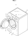
- FIG. 1 is a view illustrating an appearance of a laundry treating apparatus according to an embodiment of the disclosure.
- FIG. 2 is a cross-sectional view schematically illustrating a main configuration of the laundry treating apparatus according to an embodiment of the disclosure.
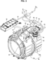
- FIG. 3 is a perspective view illustrating the main configuration of the laundry treating apparatus according to an embodiment of the disclosure.
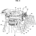
- FIG. 4 is a perspective view illustrating the main configuration of the laundry treating apparatus according to an embodiment of the disclosure when viewed from another angle.
- FIG. 5 is an exploded view illustrating a drying duct and a connection duct according to an embodiment of the disclosure.
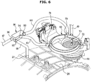
- FIG. 6 is a perspective view illustrating the main configuration of the laundry treating apparatus according to an embodiment of the disclosure when viewed from another angle.
- a laundry treating apparatus 1 includes a cabinet 10 provided to form an exterior of the laundry treating apparatus 1, a tub 20 provided in the cabinet 10 to store wash water, a drum 30 rotatably installed on the inside of the tub 20 to store and wash laundry, and a drying duct 50 configured to dry laundry by supplying heat air to the tub 20.
- the cabinet 10 may be formed in a substantially box shape, and an inlet 12 through which laundry is introduced into the drum 30 may be formed in a front plate 11 of the cabinet 10.
- a door 14 may be coupled to the cabinet 10 to open and close the inlet 12.
- a control panel 16 configured to display various information of the laundry treating apparatus 1 and configured to be manipulated to drive the laundry treating apparatus 1 may be provided above the front plate 11.
- the tub 20 may be formed to have a substantially cylindrical shape, and an opening 22 may be formed on the front surface of the tub 20 so as to correspond to the inlet 12 of the cabinet 10.
- a diaphragm 28 may be installed between the inlet 12 of the cabinet 10 and the opening 22 of the tub 20 to guide the laundry.
- the tub 20 may be formed by assembling a tub front portion 20a (refer to FIG. 3 ) and a tub rear portion 20b (refer to FIG. 3 ).
- the tub 20 may be supported by a damper 21.
- the drum 30 may be formed in a cylindrical shape so as to correspond to the shape of the tub 20.
- a through hole 31 may be formed on a circumferential surface of the drum 30 so that wash water and air may flow between the tub 20 and the drum 30 through the thorough hole 31.
- a lifter 32 may be formed on an inner circumferential surface of the drum 30 so as to lift and drop laundry when the drum 30 is rotated.
- a motor 36 may be installed at the rear of the tub 20 to rotate the drum 30.
- the motor 36 may include a stator configured to generate magnetic force when electricity is applied, and a rotor configured to be rotated by electromagnetically interacting with the stator.
- a rotational force generated by the motor 36 may be transmitted to the drum 30 through a rotary shaft 34.
- a bearing housing 35 configured to rotatably support the rotary shaft 34 may be installed at the rear of the tub 20.
- a flange 33 configured to receive the rotational force from the rotary shaft 34 may be coupled to the rear surface of the drum 30.
- the drying duct 50 may suction humid air of the tub 20 and heat the humid air and then circulate the heated air to the tub 20.
- a blower fan 55 configured to blow air
- a motor 56 configured to rotate the blower fan 55
- a heater 57 configured to heat air may be installed in the drying duct 50.
- the drying duct 50 may be provided above the tub 20.
- the laundry treating apparatus 1 may include a connection duct 60 configured to connect the tub 20 to the drying duct 50.
- the connection duct 60 may guide a portion of air of an inside 23 of the tub 20 and discharge another portion of the air of the inside 23 of the tub 20 to the outside of the tub 20.
- connection duct 60 and the drying duct 50 may be directly connected to each other.
- the connection duct 60 and the tub 20 may be connected through a main connection hose 81 and an auxiliary connection hose 82.
- Air which is sucked into the connection duct 60 through the main connection hose 81, may be guided to the drying duct 50.
- One end of the main connection hose 81 may be coupled to a main connection pipe 25 of the tub 20, and the other end of the main connection hose 81 may be coupled to a main connection port 66 of the connection duct 60.
- Air which is sucked into the connection duct 60 through the auxiliary connection hose 82, may be discharged to the outside of the tub 20.
- One end of the auxiliary connection hose 82 may be coupled to an auxiliary connection pipe 26 (refer to FIG. 4 ) of the tub 20, and the other end of the auxiliary connection hose 82 may be coupled to an auxiliary connection port 67 (refer to FIG. 4 ) of the connection duct 60.
- the laundry treating apparatus 1 may include a detergent supply device 40 configured to supply detergent to the tub 20 together with wash water. Wash water supplied from an external water supply source may be introduced into the detergent supply device 40 via a first water supply hose 45. Detergent or wash water of the detergent supply device 40 may be introduced into the tub 20 via a second water supply hose 46.
- the first water supply hose 45 may be provided with a water supply valve 42 configured to regulate the supply of the wash water.
- a filter 72 (refer to FIG. 6 ) may be installed on the main connection port 66 of the connection duct 60 so as to prevent lint, which is contained in air introduced from the tub 20, from moving to the connection duct 60.
- the laundry treating apparatus 1 may include a wash water nozzle 73 (refer to FIG. 6 ) configured to inject wash water to the filter 72 to clean the filter 72.
- the laundry treating apparatus 1 may include a wash water hose 49 configured to supply wash water to the wash water nozzle 73 from the external water supply source.
- the wash water hose 49 may be provided with a wash water valve 44 configured to regulate the supply of the wash water.
- the laundry treating apparatus 1 may include a condenser 90 configured to condense the humid air of the tub 20 by using cooling water.
- the condenser 90 may receive the cooling water from the external water supply source and provide the supplied cooling water into the tub 20.
- the condenser 90 may be connected to the connection duct 60 to suck a portion of the air introduced into the connection duct 60 from the tub 20.
- the condenser 90 may condense the air, which is sucked from the connection duct 60, and then return the condensed air to the connection duct 60.
- connection duct 60 may be guided to the drying duct 50.
- Another portion of the air of the connection duct 60 may be guided to the condenser 90 and condensed and then returned to the connection duct 60.
- the drying duct 50 may be formed by assembling a drying duct upper plate 51 and a drying duct lower plate 52. One end of the drying duct 50 may be coupled to the connection duct 60, and the other end of the drying duct 50 maybe coupled to the diaphragm 28 by penetrating the diaphragm 28.
- the blower fan 55 configured to suck air of the tub 20 and the heater 57 configured to heat the sucked air may be arranged in the drying duct 50.
- a packing 58 may be coupled between the drying duct 50 and the connection duct 60 to prevent leakage of the air.
- the laundry treating apparatus 1 may include an input hose 84 configured to guide the air of the connection duct 60 to the condenser 90 by connecting the connection duct 60 to the condenser 90, and a return hose 85 configured to return air, which is dried by being condensed by the condenser 90, to the connection duct 60 by connecting the condenser 90 to the connection duct 60.
- One end of the input hose 84 may be coupled to an input port 70 of the connection duct 60 and the other end of the input hose 84 maybe coupled to an air inlet port 93 of the condenser 90.
- the laundry treating apparatus 1 may include a first cooling water hose 47 configured to supply cooling water to the condenser 90 from the external water supply source, and a second cooling water hose 48 configured to guide the cooling water of the condenser 90 to the tub 20.
- One end of the first cooling water hose 47 may be coupled to a cooling water inlet port 96 of the condenser 90.
- One end of the second cooling water hose 48 may be coupled to a cooling water outlet port 97 of the condenser 90, and the other end of the second cooling water hose 48 maybe coupled to a cooling water inlet 27 of the tub 20.
- the first cooling water hose 47 may be provided with a cooling water valve 43 configured to regulate the supply of the cooling water.
- a valve unit 41 may include the water supply valve 42, the cooling water valve 43, and the wash water valve 44.
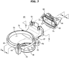
- FIG. 7 is an exploded view illustrating the connection duct according to an embodiment of the disclosure.
- FIG. 8 is a cross-sectional view taken along line I-I of FIG. 7 .
- FIG. 9 is a cross-sectional view taken along line II-II of FIG. 7 .
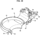
- FIG. 10 is a cross-sectional view taken along line III-III of FIG. 7 .
- connection duct 60 According to an embodiment of the disclosure will be described with reference to FIGS. 7 to 10 .
- connection duct 60 may be formed by assembling a first member 61 and a second member 62.
- the first member 61 and the second member 62 may be assembled to each other through a hook 63.
- the structure of the connection duct 60 is not limited thereto, and thus the connection duct 60 may be formed as a single piece.
- the connection duct 60 may include a guide 64 provided to protrude to guide the air, which is sucked from the tub 20, to the drying duct 50, and an engaging portion 65 coupled to the drying duct 50.
- the guide 64 and the engaging portion 65 may be formed in a circular or arc shape.
- the engaging portion 65 may be formed on the outside of the guide 64.
- connection duct 60 includes a connection chamber 75 configured to suck a portion of the air of the tub 20 and guide the sucked air to the drying duct 50, and a discharge chamber 76 configured to suck another portion of the air of the tub 20 and discharge the sucked air to the outside of the tub 20.
- the discharge chamber 76 and the connection chamber 75 may be formed so as not to communicate with each other. That is, the air introduced into the discharge chamber 76 from the tub 20 and the air introduced into the connection chamber 75 from the tub 20 may not be mixed with each other.
- connection duct 60 may include the main connection port 66, to which the main connection hose 81 is coupled, to guide the air of the tub 20 to the connection chamber 75, and the auxiliary connection port 67, to which the auxiliary connection hose 82 is coupled, to guide the air of the tub 20 to the discharge chamber 76.
- the filter 72 configured to remove the lint of the air, which is introduced to the connection chamber 75 from the tub 20, may be installed in the main connection port 66.
- the wash water nozzle 73 configured to inject wash water to the filter 72 to clean the filter 72 by receiving wash water from the external water supply source maybe installed in the connection duct 60.
- the connection duct 60 may include a discharge port 68, to which a discharge hose 83 is coupled, to discharge the air of the discharge chamber 76 to the outside of the tub 20.
- the discharge hose 83 may extend outwardly of the cabinet 10.
- the discharge hose 83 may be connected to a drain pipe separately installed on the outside of the cabinet 10. Therefore, the humid air and condensed water of the tub 20 may be discharged to the outside through the discharge hose 83 and the drain pipe.
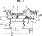
- the humid air of the inside 23 of the tub 20 may be sucked into the connection chamber 75 of the connection duct 60 through the main connection hose 81.
- the air, which is sucked into the connection chamber 75, may be guided to the 50 and heated and then returned into the tub 20.
- a portion of the humid air of the inside 23 of the tub 20 may be sucked into the discharge chamber 76 of the connection duct 60 through the auxiliary connection hose 82 by the pressure of the inside 23 of the tub 20. Most of the air of the inside 23 of the tub 20 may be sucked into the connection chamber 75 and a portion of the remaining air thereof may be sucked into the discharge chamber 76.
- Air which is sucked into the discharge chamber 76, may be mixed and exchange heat with a surface of the discharge chamber 76 while staying in the discharge chamber 76. Accordingly, air, which is heated by the heater 57 and thus has a high temperature during the drying operation, may perform heat exchange in the discharge chamber 76 and thus the temperature of the air may be lowered. Further, because the heat exchange is performed in the discharge chamber 76, moisture contained in the air may be condensed. The condensed water and air may be discharged to the outside of the cabinet 10 through the discharge hose 83.
- the connection duct 60 includes a suction chamber 77 configured to suck dry air from the outside of the tub 20.
- the suction chamber 77 may be formed in communication with the connection chamber 75 (refer to FIG. 9 ). Therefore, the dry outside air, which is sucked into the suction chamber 77, may be guided to the drying duct 50 and circulated to the tub 20.
- the connection duct 60 may include a suction port 69 through which outside air is sucked into the suction chamber 77.
- the connection duct 60 includes a partition 78 formed between the discharge chamber 76 and the suction chamber 77.
- the discharge chamber 76 may be formed at one side of the partition 78, and the suction chamber 77 may be formed at an opposite side of the partition 78.
- the air of the discharge chamber 76 and the air of the suction chamber 77 may exchange heat through the partition 78. That is, the high temperature air of the discharge chamber 76 exchanges heat with the air of the suction chamber 77, which has a relatively low temperature, so that the temperature of the air of the discharge chamber 76 is decreased and the temperature of the air of the suction chamber 77 is increased. As a result, the air discharged through the discharge chamber 76 may be discharged at a temperature that is not too high, and thus discomfort of the user may be prevented. Further, because the temperature of the air, which is circulated to the tub 20 through the suction chamber 77, is increased, energy for heating air may be saved and thus the drying efficiency may be improved.
- the partition 78 may be provided with a slit 79 to improve heat exchange between the discharge chamber 76 and the suction chamber 77. As the air of the discharge chamber 76 and the air of the suction chamber 77 are exchanged via the slit 79, heat exchange may be more smoothly performed.
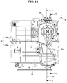
- FIG. 11 is a plan view illustrating the laundry treating apparatus according to an embodiment of the disclosure.
- FIG. 12 is a cross-sectional view taken along line IV-IV of FIG. 11 , illustrating a circulation flow path of the laundry treating apparatus according to an embodiment of the disclosure.
- FIG. 13 is a cross-sectional view taken along line V-V of FIG. 11 , illustrating a suction flow path of the laundry treating apparatus according to the embodiment of the disclosure.
- FIG. 14 is a cross-sectional view taken along line VI-VI of FIG. 11 , illustrating a discharge flow path of the laundry treating apparatus according to an embodiment of the disclosure.
- a portion of the air of the tub 20 may be sucked into the drying duct 50 through the main connection hose 81 and the connection duct 60.
- the air sucked into the drying duct 50 may be heated by the heater 57 and the heated air may be circulated into the tub 20. That is, a circulation flow path A may be formed between the tub 20 and the drying duct 50 during the drying operation, and thus the laundry accommodated in the drum 30 may be dried by hot air.
- air may be circulated along the circulation flow path A, and at the same time, the dry outside air may be joined to the circulation flow path A through a suction flow path B.
- the suction chamber 77 of the connection duct 60 may form the suction flow path B. Outside air may be sucked into the suction chamber 77 of the connection duct 60 through the suction port 69 of the connection duct 60. Because the dry outside air is supplied to the inside of the tub 20 through the suction flow path B, the drying efficiency may be improved.
- air may be circulated along the circulation flow path A, and at the same time, a portion of the humid air of the tub 20 may be discharged to the outside of the tub 20 through a discharge flow path C.
- the discharge chamber 76 of the connection duct 60 may form the discharge flow path C.
- a portion of the air of the tub 20 may be discharged to the outside of the tub 20 through the auxiliary connection hose 82, the discharge chamber 76, and the discharge hose 83. Accordingly, a portion of the humid air of the tub 20 may be discharged to the outside through the discharge flow path C, thereby improving the drying efficiency.
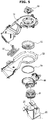
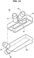
- FIG. 15 is an exploded view of a condenser according to an embodiment of the disclosure.
- FIG. 16 is an exploded view of the condenser according to an embodiment of the disclosure when viewed from the bottom.
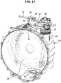
- FIG. 17 is a view illustrating a state in which cooling water flows on a rear surface of the tub of the laundry treating apparatus according to an embodiment of the disclosure.
- the condenser 90 may suck a portion of the air of the connection duct 60, receive cooling water from the external water supply source, and condense the air sucked from the connection duct 60 with the supplied cooling water.
- the condensed and dried air may be returned to the connection duct 60.
- the condenser 90 may supply cooling water, which is supplied from the external water supply source, into the tub 20. That is, the primary condensation of the air may be performed in the condenser 90 by the cooling water, and the secondary condensation of the air may be performed in the tub 20 by the cooling water.
- the condenser 90 may be formed by assembling a condenser upper plate 91 with a condenser lower plate 92.
- the air inlet port 93 configured to suck air from the connection duct 60
- an air return port 94 configured to return the condensed air to the connection duct 60
- a condensing flow path 95 configured to connect the air inlet port 93 to the air return port 94 may be formed on the condenser upper plate 91.
- a cooling water inlet port 96 through which cooling water flows from the external water supply source, a cooling water outlet port 97 configured to supply cooling water to the tub 20, and a cooling water flow path 98 configured to connect the cooling water inlet port 96 to the cooling water outlet port 97 may be formed on the condenser lower plate 92.
- the cooling water flow path 98 may be inclined so that the cooling water introduced into the cooling water inlet port 96 may flow into the cooling water outlet port 97 by its own weight.
- the condensing flow path 95 and the cooling water flow path 98 may be formed to be adjacent to each other vertically so that the air flowing in the condensing flow path 95 and the cooling water flowing in the cooling water flow path 98 may be in contact with each other to exchange heat.
- the cooling water which firstly condenses air in the condenser 90, may be guided to the cooling water inlet 27 of the tub 20 through the second cooling water hose 48, and then the cooling water may secondarily condense air in the tub 20 while flowing down along a rear surface 24 of the tub 20.
- the laundry treating apparatus may have an improved drying efficiency by heating the humid air of the tub and circulating the heated air while discharging a portion of the humid air of the tub to the outside and sucking outside air and supplying the sucked air to the tub.
- connection duct configured to connect the tub to the drying duct includes the discharge chamber configured to discharge a portion of the humid air of the tub to the outside. Therefore, hot humid air may not be discharged to the outside as it is, but may be heat-exchanged through the discharge chamber and then discharged to the outside.
- the condenser is installed on the cooling water flow path configured to supply cooling water to the back side of the tub, and a portion of the air circulating between the tub and the drying duct is guided to the condenser. Therefore, the air of the tub is condensed firstly in the condenser, and the air is condensed secondarily in the tub, thereby improving the drying efficiency.
Claims (10)
- Appareil de traitement du linge (1) ayant des fonctions de lavage et de séchage, comprenant :une carrosserie (10) ;une cuve (20) disposée dans la carrosserie ;un conduit de séchage (50) configuré pour chauffer de l'air et alimenter la cuve en air chauffé ; etun conduit de raccordement (60) prévu entre la cuve (20) et le conduit de séchage (50),
dans lequel le conduit de raccordement (60) comprend :une chambre de raccordement (75) configurée pour guider une première partie d'air depuis l'intérieur de la cuve (20) jusqu'au conduit de séchage (50) ;une chambre d'évacuation (76) qui ne communique pas avec la chambre de raccordement (75), configurée pour aspirer une deuxième partie d'air depuis l'intérieur de la cuve (20) et pour évacuer l'air aspiré à l'extérieur de la carrosserie (10) ;une chambre d'aspiration (77) en communication avec la chambre de raccordement (75) et configurée pour aspirer de l'air sec depuis l'extérieur de la cuve (20) dans la chambre de raccordement (75) ;caractérisé en ce que
une séparation (78) est formée entre la chambre d'évacuation (76) et la chambre d'aspiration (77), dans lequel ladite séparation (78) est configurée de telle façon que l'air dans la chambre d'évacuation (76) et l'air dans la chambre d'aspiration (77) échangent de la chaleur à travers la séparation (78). - Appareil de traitement du linge selon la revendication 1, comprenant en outre :
un tuyau de raccordement auxiliaire (82) configuré pour raccorder la cuve (20) au conduit de raccordement (60) afin de guider la deuxième partie d'air depuis l'intérieur de la cuve jusqu'à la chambre d'évacuation (76). - Appareil de traitement du linge selon la revendication 2, comprenant en outre :
un tuyau de raccordement principal (81) configuré pour raccorder la cuve (20) au conduit de raccordement (60) afin de guider la première partie d'air depuis l'intérieur de la cuve jusqu'à la chambre de raccordement (75). - Appareil de traitement du linge selon la revendication 1, comprenant en outre :
un tuyau d'évacuation (83) couplé au conduit de raccordement de façon à guider l'air de la chambre d'évacuation (76) jusqu'à l'extérieur de la carrosserie (10) . - Appareil de traitement du linge selon la revendication 1, dans lequel
une fente (79) est formée sur la séparation (78) afin de permettre à l'échange de chaleur de se faire entre l'air de la chambre d'évacuation (76) et l'air de la chambre d'aspiration (77). - Appareil de traitement du linge selon la revendication 1, comprenant en outre :
un condenseur (90) raccordé au conduit de raccordement (60) pour aspirer la première partie d'air depuis le conduit de raccordement (60) et pour condenser l'air aspiré. - Appareil de traitement du linge selon la revendication 6, dans lequel
le condenseur condense de l'air qui est aspiré depuis le conduit de raccordement et renvoie l'air condensé jusqu'au conduit de raccordement (60). - Appareil de traitement du linge selon la revendication 6, dans lequel
le condenseur condense de l'air qui est aspiré depuis le conduit de raccordement (60) avec de l'eau de refroidissement reçue depuis une source d'alimentation en eau extérieure et le condenseur alimente l'eau de refroidissement à l'intérieur de la cuve. - Appareil de traitement du linge selon la revendication 6, dans lequel
le condenseur comprend un orifice d'entrée d'air (93) configuré pour aspirer de l'air depuis le conduit de raccordement (60), un orifice de retour d'air (94) configuré pour renvoyer de l'air jusqu'au conduit de raccordement (60), et un trajet d'écoulement de condensation (95) configuré pour raccorder l'orifice d'entrée d'air à l'orifice de retour d'air. - Appareil de traitement du linge selon la revendication 6, dans lequel
le condenseur comprend un orifice d'entrée d'eau de refroidissement (96) par lequel de l'eau de refroidissement est introduite depuis la source d'alimentation en eau extérieure, un orifice de sortie d'eau de refroidissement (97) configuré pour évacuer l'eau de refroidissement jusqu'à l'extérieur du condenseur, et un trajet d'écoulement d'eau de refroidissement (98) configuré pour raccorder l'orifice d'entrée d'eau de refroidissement à l'orifice de sortie d'eau de refroidissement.
Applications Claiming Priority (1)
| Application Number | Priority Date | Filing Date | Title |
|---|---|---|---|
| KR1020180170523A KR102655369B1 (ko) | 2018-12-27 | 2018-12-27 | 세탁물 처리 장치 |
Publications (2)
| Publication Number | Publication Date |
|---|---|
| EP3674474A1 EP3674474A1 (fr) | 2020-07-01 |
| EP3674474B1 true EP3674474B1 (fr) | 2021-06-16 |
Family
ID=69024202
Family Applications (1)
| Application Number | Title | Priority Date | Filing Date |
|---|---|---|---|
| EP19219668.1A Active EP3674474B1 (fr) | 2018-12-27 | 2019-12-24 | Appareil de traitement du linge |
Country Status (3)
| Country | Link |
|---|---|
| EP (1) | EP3674474B1 (fr) |
| KR (1) | KR102655369B1 (fr) |
| WO (1) | WO2020138990A1 (fr) |
Family Cites Families (11)
| Publication number | Priority date | Publication date | Assignee | Title |
|---|---|---|---|---|
| KR100601433B1 (ko) * | 2004-07-09 | 2006-07-14 | 주식회사 대우일렉트로닉스 | 드럼 세탁기용 건조장치 |
| DE102008020556A1 (de) * | 2008-04-24 | 2009-10-29 | BSH Bosch und Siemens Hausgeräte GmbH | Ablufttrockner mit verminderter Kondensatbildung sowie Verfahren zu seinem Betrieb |
| EP2716808B1 (fr) * | 2011-04-18 | 2018-09-05 | LG Electronics Inc. | Machine à laver |
| KR102017695B1 (ko) * | 2013-01-25 | 2019-09-03 | 엘지전자 주식회사 | 의류처리장치 |
| KR101706663B1 (ko) * | 2013-02-20 | 2017-02-27 | 삼성전자주식회사 | 드럼 세탁기 |
| KR200473784Y1 (ko) * | 2013-02-28 | 2014-07-31 | 고창오 | 의류 건조기용 열풍 장치 |
| KR20140132801A (ko) * | 2013-05-06 | 2014-11-19 | 삼성전자주식회사 | 드럼 세탁기 |
| CN104514114B (zh) * | 2013-09-03 | 2017-10-27 | Lg电子株式会社 | 衣物处理设备 |
| KR20150081602A (ko) * | 2014-01-06 | 2015-07-15 | 삼성전자주식회사 | 세탁 건조기 및 그 제어방법 |
| DE102014224214A1 (de) * | 2014-11-27 | 2016-06-02 | BSH Hausgeräte GmbH | Wäschetrocknungsgerät und Verfahren zum Betreiben eines Wäschetrocknungsgeräts |
| KR102521491B1 (ko) * | 2015-12-11 | 2023-04-14 | 삼성전자주식회사 | 건조 장치 및 이를 포함하는 세탁건조기 |
-
2018
- 2018-12-27 KR KR1020180170523A patent/KR102655369B1/ko active IP Right Grant
-
2019
- 2019-12-24 EP EP19219668.1A patent/EP3674474B1/fr active Active
- 2019-12-27 WO PCT/KR2019/018543 patent/WO2020138990A1/fr active Application Filing
Also Published As
| Publication number | Publication date |
|---|---|
| KR102655369B1 (ko) | 2024-04-08 |
| WO2020138990A1 (fr) | 2020-07-02 |
| EP3674474A1 (fr) | 2020-07-01 |
| KR20200080744A (ko) | 2020-07-07 |
Similar Documents
| Publication | Publication Date | Title |
|---|---|---|
| US10941514B2 (en) | Drying apparatus and laundry drying machine including the same | |
| US9903067B2 (en) | Laundry machine | |
| CN113355841A (zh) | 堆叠式衣物处理装置 | |
| EP2423376B1 (fr) | Machine de traitement du linge | |
| EP2319979B1 (fr) | Machine à laver et à sécher | |
| US20090113743A1 (en) | Dryer having intake duct with heater integrated therein | |
| EP2829653B1 (fr) | Appareil de séchage de linge | |
| KR102052373B1 (ko) | 의류처리장치 | |
| KR20100034077A (ko) | 의류건조기 | |
| WO2008056836A1 (fr) | Dispositif d'alimentation en eau pour un sèche-linge et procédé de régulation associé | |
| US10196768B2 (en) | Washing machine | |
| KR101319881B1 (ko) | 복합 의류 처리 장치 | |
| EP1595993A1 (fr) | Sèche-linge | |
| CN210104319U (zh) | 衣物处理设备 | |
| EP3674474B1 (fr) | Appareil de traitement du linge | |
| CN209958110U (zh) | 衣物处理设备 | |
| KR20210056305A (ko) | 의류처리장치 | |
| KR20050108114A (ko) | 의류 건조기용 배기챔버 | |
| EP3336237B1 (fr) | Appareil de traitement du linge | |
| JP4896503B2 (ja) | 洗濯乾燥機 | |
| JP2008284142A (ja) | 衣類乾燥機 | |
| JP2020010959A (ja) | 衣類乾燥機 | |
| KR102243927B1 (ko) | 세탁기 | |
| KR102017695B1 (ko) | 의류처리장치 | |
| EP3943656B1 (fr) | Dispositif de traitement de linge |
Legal Events
| Date | Code | Title | Description |
|---|---|---|---|
| PUAI | Public reference made under article 153(3) epc to a published international application that has entered the european phase |
Free format text: ORIGINAL CODE: 0009012 |
|
| STAA | Information on the status of an ep patent application or granted ep patent |
Free format text: STATUS: REQUEST FOR EXAMINATION WAS MADE |
|
| 17P | Request for examination filed |
Effective date: 20191224 |
|
| AK | Designated contracting states |
Kind code of ref document: A1 Designated state(s): AL AT BE BG CH CY CZ DE DK EE ES FI FR GB GR HR HU IE IS IT LI LT LU LV MC MK MT NL NO PL PT RO RS SE SI SK SM TR |
|
| AX | Request for extension of the european patent |
Extension state: BA ME |
|
| RIC1 | Information provided on ipc code assigned before grant |
Ipc: D06F 58/20 20060101ALN20201214BHEP Ipc: D06F 25/00 20060101ALI20201214BHEP Ipc: D06F 58/02 20060101AFI20201214BHEP |
|
| GRAP | Despatch of communication of intention to grant a patent |
Free format text: ORIGINAL CODE: EPIDOSNIGR1 |
|
| STAA | Information on the status of an ep patent application or granted ep patent |
Free format text: STATUS: GRANT OF PATENT IS INTENDED |
|
| INTG | Intention to grant announced |
Effective date: 20210122 |
|
| RIN1 | Information on inventor provided before grant (corrected) |
Inventor name: KIM, ZOO HYEONG Inventor name: HAH, MYUNG YOON Inventor name: SEO, JEONG KI |
|
| GRAS | Grant fee paid |
Free format text: ORIGINAL CODE: EPIDOSNIGR3 |
|
| GRAA | (expected) grant |
Free format text: ORIGINAL CODE: 0009210 |
|
| STAA | Information on the status of an ep patent application or granted ep patent |
Free format text: STATUS: THE PATENT HAS BEEN GRANTED |
|
| AK | Designated contracting states |
Kind code of ref document: B1 Designated state(s): AL AT BE BG CH CY CZ DE DK EE ES FI FR GB GR HR HU IE IS IT LI LT LU LV MC MK MT NL NO PL PT RO RS SE SI SK SM TR |
|
| REG | Reference to a national code |
Ref country code: GB Ref legal event code: FG4D |
|
| REG | Reference to a national code |
Ref country code: CH Ref legal event code: EP |
|
| REG | Reference to a national code |
Ref country code: DE Ref legal event code: R096 Ref document number: 602019005418 Country of ref document: DE |
|
| REG | Reference to a national code |
Ref country code: AT Ref legal event code: REF Ref document number: 1402426 Country of ref document: AT Kind code of ref document: T Effective date: 20210715 |
|
| REG | Reference to a national code |
Ref country code: IE Ref legal event code: FG4D |
|
| REG | Reference to a national code |
Ref country code: LT Ref legal event code: MG9D |
|
| PG25 | Lapsed in a contracting state [announced via postgrant information from national office to epo] |
Ref country code: LT Free format text: LAPSE BECAUSE OF FAILURE TO SUBMIT A TRANSLATION OF THE DESCRIPTION OR TO PAY THE FEE WITHIN THE PRESCRIBED TIME-LIMIT Effective date: 20210616 Ref country code: HR Free format text: LAPSE BECAUSE OF FAILURE TO SUBMIT A TRANSLATION OF THE DESCRIPTION OR TO PAY THE FEE WITHIN THE PRESCRIBED TIME-LIMIT Effective date: 20210616 Ref country code: FI Free format text: LAPSE BECAUSE OF FAILURE TO SUBMIT A TRANSLATION OF THE DESCRIPTION OR TO PAY THE FEE WITHIN THE PRESCRIBED TIME-LIMIT Effective date: 20210616 Ref country code: BG Free format text: LAPSE BECAUSE OF FAILURE TO SUBMIT A TRANSLATION OF THE DESCRIPTION OR TO PAY THE FEE WITHIN THE PRESCRIBED TIME-LIMIT Effective date: 20210916 |
|
| REG | Reference to a national code |
Ref country code: AT Ref legal event code: MK05 Ref document number: 1402426 Country of ref document: AT Kind code of ref document: T Effective date: 20210616 |
|
| REG | Reference to a national code |
Ref country code: NL Ref legal event code: MP Effective date: 20210616 |
|
| PG25 | Lapsed in a contracting state [announced via postgrant information from national office to epo] |
Ref country code: NO Free format text: LAPSE BECAUSE OF FAILURE TO SUBMIT A TRANSLATION OF THE DESCRIPTION OR TO PAY THE FEE WITHIN THE PRESCRIBED TIME-LIMIT Effective date: 20210916 Ref country code: LV Free format text: LAPSE BECAUSE OF FAILURE TO SUBMIT A TRANSLATION OF THE DESCRIPTION OR TO PAY THE FEE WITHIN THE PRESCRIBED TIME-LIMIT Effective date: 20210616 Ref country code: RS Free format text: LAPSE BECAUSE OF FAILURE TO SUBMIT A TRANSLATION OF THE DESCRIPTION OR TO PAY THE FEE WITHIN THE PRESCRIBED TIME-LIMIT Effective date: 20210616 Ref country code: SE Free format text: LAPSE BECAUSE OF FAILURE TO SUBMIT A TRANSLATION OF THE DESCRIPTION OR TO PAY THE FEE WITHIN THE PRESCRIBED TIME-LIMIT Effective date: 20210616 Ref country code: GR Free format text: LAPSE BECAUSE OF FAILURE TO SUBMIT A TRANSLATION OF THE DESCRIPTION OR TO PAY THE FEE WITHIN THE PRESCRIBED TIME-LIMIT Effective date: 20210917 |
|
| PG25 | Lapsed in a contracting state [announced via postgrant information from national office to epo] |
Ref country code: SM Free format text: LAPSE BECAUSE OF FAILURE TO SUBMIT A TRANSLATION OF THE DESCRIPTION OR TO PAY THE FEE WITHIN THE PRESCRIBED TIME-LIMIT Effective date: 20210616 Ref country code: RO Free format text: LAPSE BECAUSE OF FAILURE TO SUBMIT A TRANSLATION OF THE DESCRIPTION OR TO PAY THE FEE WITHIN THE PRESCRIBED TIME-LIMIT Effective date: 20210616 Ref country code: NL Free format text: LAPSE BECAUSE OF FAILURE TO SUBMIT A TRANSLATION OF THE DESCRIPTION OR TO PAY THE FEE WITHIN THE PRESCRIBED TIME-LIMIT Effective date: 20210616 Ref country code: PT Free format text: LAPSE BECAUSE OF FAILURE TO SUBMIT A TRANSLATION OF THE DESCRIPTION OR TO PAY THE FEE WITHIN THE PRESCRIBED TIME-LIMIT Effective date: 20211018 Ref country code: CZ Free format text: LAPSE BECAUSE OF FAILURE TO SUBMIT A TRANSLATION OF THE DESCRIPTION OR TO PAY THE FEE WITHIN THE PRESCRIBED TIME-LIMIT Effective date: 20210616 Ref country code: AT Free format text: LAPSE BECAUSE OF FAILURE TO SUBMIT A TRANSLATION OF THE DESCRIPTION OR TO PAY THE FEE WITHIN THE PRESCRIBED TIME-LIMIT Effective date: 20210616 Ref country code: ES Free format text: LAPSE BECAUSE OF FAILURE TO SUBMIT A TRANSLATION OF THE DESCRIPTION OR TO PAY THE FEE WITHIN THE PRESCRIBED TIME-LIMIT Effective date: 20210616 Ref country code: EE Free format text: LAPSE BECAUSE OF FAILURE TO SUBMIT A TRANSLATION OF THE DESCRIPTION OR TO PAY THE FEE WITHIN THE PRESCRIBED TIME-LIMIT Effective date: 20210616 Ref country code: SK Free format text: LAPSE BECAUSE OF FAILURE TO SUBMIT A TRANSLATION OF THE DESCRIPTION OR TO PAY THE FEE WITHIN THE PRESCRIBED TIME-LIMIT Effective date: 20210616 |
|
| PG25 | Lapsed in a contracting state [announced via postgrant information from national office to epo] |
Ref country code: PL Free format text: LAPSE BECAUSE OF FAILURE TO SUBMIT A TRANSLATION OF THE DESCRIPTION OR TO PAY THE FEE WITHIN THE PRESCRIBED TIME-LIMIT Effective date: 20210616 |
|
| REG | Reference to a national code |
Ref country code: DE Ref legal event code: R097 Ref document number: 602019005418 Country of ref document: DE |
|
| PLBE | No opposition filed within time limit |
Free format text: ORIGINAL CODE: 0009261 |
|
| STAA | Information on the status of an ep patent application or granted ep patent |
Free format text: STATUS: NO OPPOSITION FILED WITHIN TIME LIMIT |
|
| PG25 | Lapsed in a contracting state [announced via postgrant information from national office to epo] |
Ref country code: DK Free format text: LAPSE BECAUSE OF FAILURE TO SUBMIT A TRANSLATION OF THE DESCRIPTION OR TO PAY THE FEE WITHIN THE PRESCRIBED TIME-LIMIT Effective date: 20210616 |
|
| 26N | No opposition filed |
Effective date: 20220317 |
|
| PG25 | Lapsed in a contracting state [announced via postgrant information from national office to epo] |
Ref country code: AL Free format text: LAPSE BECAUSE OF FAILURE TO SUBMIT A TRANSLATION OF THE DESCRIPTION OR TO PAY THE FEE WITHIN THE PRESCRIBED TIME-LIMIT Effective date: 20210616 |
|
| PG25 | Lapsed in a contracting state [announced via postgrant information from national office to epo] |
Ref country code: MC Free format text: LAPSE BECAUSE OF FAILURE TO SUBMIT A TRANSLATION OF THE DESCRIPTION OR TO PAY THE FEE WITHIN THE PRESCRIBED TIME-LIMIT Effective date: 20210616 Ref country code: IT Free format text: LAPSE BECAUSE OF FAILURE TO SUBMIT A TRANSLATION OF THE DESCRIPTION OR TO PAY THE FEE WITHIN THE PRESCRIBED TIME-LIMIT Effective date: 20210616 |
|
| REG | Reference to a national code |
Ref country code: BE Ref legal event code: MM Effective date: 20211231 |
|
| PG25 | Lapsed in a contracting state [announced via postgrant information from national office to epo] |
Ref country code: LU Free format text: LAPSE BECAUSE OF NON-PAYMENT OF DUE FEES Effective date: 20211224 Ref country code: IE Free format text: LAPSE BECAUSE OF NON-PAYMENT OF DUE FEES Effective date: 20211224 |
|
| PG25 | Lapsed in a contracting state [announced via postgrant information from national office to epo] |
Ref country code: FR Free format text: LAPSE BECAUSE OF NON-PAYMENT OF DUE FEES Effective date: 20211231 Ref country code: BE Free format text: LAPSE BECAUSE OF NON-PAYMENT OF DUE FEES Effective date: 20211231 |
|
| PG25 | Lapsed in a contracting state [announced via postgrant information from national office to epo] |
Ref country code: CY Free format text: LAPSE BECAUSE OF FAILURE TO SUBMIT A TRANSLATION OF THE DESCRIPTION OR TO PAY THE FEE WITHIN THE PRESCRIBED TIME-LIMIT Effective date: 20210616 |
|
| PG25 | Lapsed in a contracting state [announced via postgrant information from national office to epo] |
Ref country code: HU Free format text: LAPSE BECAUSE OF FAILURE TO SUBMIT A TRANSLATION OF THE DESCRIPTION OR TO PAY THE FEE WITHIN THE PRESCRIBED TIME-LIMIT; INVALID AB INITIO Effective date: 20191224 |
|
| REG | Reference to a national code |
Ref country code: CH Ref legal event code: PL |
|
| PG25 | Lapsed in a contracting state [announced via postgrant information from national office to epo] |
Ref country code: LI Free format text: LAPSE BECAUSE OF NON-PAYMENT OF DUE FEES Effective date: 20221231 Ref country code: CH Free format text: LAPSE BECAUSE OF NON-PAYMENT OF DUE FEES Effective date: 20221231 |
|
| PGFP | Annual fee paid to national office [announced via postgrant information from national office to epo] |
Ref country code: GB Payment date: 20231120 Year of fee payment: 5 |
|
| PGFP | Annual fee paid to national office [announced via postgrant information from national office to epo] |
Ref country code: DE Payment date: 20231120 Year of fee payment: 5 |
|
| PG25 | Lapsed in a contracting state [announced via postgrant information from national office to epo] |
Ref country code: MK Free format text: LAPSE BECAUSE OF FAILURE TO SUBMIT A TRANSLATION OF THE DESCRIPTION OR TO PAY THE FEE WITHIN THE PRESCRIBED TIME-LIMIT Effective date: 20210616 |