EP3674187A1 - Storage unit structure for saddle riding vehicle - Google Patents
Storage unit structure for saddle riding vehicle Download PDFInfo
- Publication number
- EP3674187A1 EP3674187A1 EP19202700.1A EP19202700A EP3674187A1 EP 3674187 A1 EP3674187 A1 EP 3674187A1 EP 19202700 A EP19202700 A EP 19202700A EP 3674187 A1 EP3674187 A1 EP 3674187A1
- Authority
- EP
- European Patent Office
- Prior art keywords
- lid
- operator
- restriction
- link
- open
- Prior art date
- Legal status (The legal status is an assumption and is not a legal conclusion. Google has not performed a legal analysis and makes no representation as to the accuracy of the status listed.)
- Granted
Links
Images







Classifications
-
- B—PERFORMING OPERATIONS; TRANSPORTING
- B62—LAND VEHICLES FOR TRAVELLING OTHERWISE THAN ON RAILS
- B62J—CYCLE SADDLES OR SEATS; AUXILIARY DEVICES OR ACCESSORIES SPECIALLY ADAPTED TO CYCLES AND NOT OTHERWISE PROVIDED FOR, e.g. ARTICLE CARRIERS OR CYCLE PROTECTORS
- B62J9/00—Containers specially adapted for cycles, e.g. panniers or saddle bags
- B62J9/20—Containers specially adapted for cycles, e.g. panniers or saddle bags attached to the cycle as accessories
- B62J9/24—Containers specially adapted for cycles, e.g. panniers or saddle bags attached to the cycle as accessories on specially adapted racks, e.g. for top or side cases
-
- B—PERFORMING OPERATIONS; TRANSPORTING
- B62—LAND VEHICLES FOR TRAVELLING OTHERWISE THAN ON RAILS
- B62J—CYCLE SADDLES OR SEATS; AUXILIARY DEVICES OR ACCESSORIES SPECIALLY ADAPTED TO CYCLES AND NOT OTHERWISE PROVIDED FOR, e.g. ARTICLE CARRIERS OR CYCLE PROTECTORS
- B62J1/00—Saddles or other seats for cycles; Arrangement thereof; Component parts
- B62J1/28—Other additional equipment, e.g. back-rests for children
-
- B—PERFORMING OPERATIONS; TRANSPORTING
- B62—LAND VEHICLES FOR TRAVELLING OTHERWISE THAN ON RAILS
- B62J—CYCLE SADDLES OR SEATS; AUXILIARY DEVICES OR ACCESSORIES SPECIALLY ADAPTED TO CYCLES AND NOT OTHERWISE PROVIDED FOR, e.g. ARTICLE CARRIERS OR CYCLE PROTECTORS
- B62J17/00—Weather guards for riders; Fairings or stream-lining parts not otherwise provided for
-
- B—PERFORMING OPERATIONS; TRANSPORTING
- B62—LAND VEHICLES FOR TRAVELLING OTHERWISE THAN ON RAILS
- B62J—CYCLE SADDLES OR SEATS; AUXILIARY DEVICES OR ACCESSORIES SPECIALLY ADAPTED TO CYCLES AND NOT OTHERWISE PROVIDED FOR, e.g. ARTICLE CARRIERS OR CYCLE PROTECTORS
- B62J7/00—Luggage carriers
- B62J7/08—Equipment for securing luggage on carriers
-
- B—PERFORMING OPERATIONS; TRANSPORTING
- B62—LAND VEHICLES FOR TRAVELLING OTHERWISE THAN ON RAILS
- B62J—CYCLE SADDLES OR SEATS; AUXILIARY DEVICES OR ACCESSORIES SPECIALLY ADAPTED TO CYCLES AND NOT OTHERWISE PROVIDED FOR, e.g. ARTICLE CARRIERS OR CYCLE PROTECTORS
- B62J9/00—Containers specially adapted for cycles, e.g. panniers or saddle bags
- B62J9/20—Containers specially adapted for cycles, e.g. panniers or saddle bags attached to the cycle as accessories
- B62J9/23—Containers specially adapted for cycles, e.g. panniers or saddle bags attached to the cycle as accessories above or alongside the rear wheel
-
- B—PERFORMING OPERATIONS; TRANSPORTING
- B62—LAND VEHICLES FOR TRAVELLING OTHERWISE THAN ON RAILS
- B62J—CYCLE SADDLES OR SEATS; AUXILIARY DEVICES OR ACCESSORIES SPECIALLY ADAPTED TO CYCLES AND NOT OTHERWISE PROVIDED FOR, e.g. ARTICLE CARRIERS OR CYCLE PROTECTORS
- B62J9/00—Containers specially adapted for cycles, e.g. panniers or saddle bags
- B62J9/20—Containers specially adapted for cycles, e.g. panniers or saddle bags attached to the cycle as accessories
- B62J9/27—Containers specially adapted for cycles, e.g. panniers or saddle bags attached to the cycle as accessories characterised by mounting arrangements, e.g. quick release arrangements
-
- B—PERFORMING OPERATIONS; TRANSPORTING
- B62—LAND VEHICLES FOR TRAVELLING OTHERWISE THAN ON RAILS
- B62J—CYCLE SADDLES OR SEATS; AUXILIARY DEVICES OR ACCESSORIES SPECIALLY ADAPTED TO CYCLES AND NOT OTHERWISE PROVIDED FOR, e.g. ARTICLE CARRIERS OR CYCLE PROTECTORS
- B62J9/00—Containers specially adapted for cycles, e.g. panniers or saddle bags
- B62J9/30—Containers specially adapted for cycles, e.g. panniers or saddle bags characterised by locking arrangements, e.g. top case locks integrated in a vehicle central locking system
Definitions
- the present invention relates to a storage unit structure for a saddle riding vehicle.
- a hitherto known device uses a key rotating operation to switch between a locked state and an unlocked state of the storage member with respect to a vehicle body (see, for example, Patent Document 1).
- the key rotating operation also imposes or releases restriction on opening or closing of a lid for the storage member.
- a possible configuration may, for example, be such that a key operation for the locked state of the storage member with respect to the vehicle body is performed independently of a key operation for the restriction on opening or closing of the lid for the storage member, so that the restriction on opening or closing of the lid for the storage member can be solely performed.
- This configuration involves a complicated structure.
- the present invention has been made in view of the foregoing situation and it is an object of the present invention to achieve, in a storage unit structure for a saddle riding vehicle, a simple structure for solely switching restriction on opening or closing of a lid for a storage member independently of switching a locked state of the storage member.
- a storage unit structure for a saddle riding vehicle including a box-shaped storage member (52) removably mounted on a side of a vehicle body (50) and a rotary operator (66) that is disposed in the storage member (52) and that is rotationally operated, in which a locked state and an unlocked state of the storage member (52) with respect to the side of the vehicle body (50) are switched through an operation of the rotary operator (66),
- the storage unit structure including: a lid operator (68) that operates to open or close a lid (61) of the storage member (52); an open/close control mechanism (75) that imposes or releases restriction on opening or closing of the lid (61) by the lid operator (68); and an open/close control mechanism operation restriction portion (85) that imposes or releases restriction on the operation of the open/close control mechanism (75).
- a state of restriction on the open/close control mechanism (75) by the open/close control mechanism operation restriction portion (85) is switched in response to an operation of the rotary operator
- the open/close control mechanism operation restriction portion (85) restricts an operation of the open/close control mechanism (75), and, when the storage member (52) is in the unlocked state through an operation of the rotary operator (66), the open/close control mechanism operation restriction portion (85) releases restriction on the operation of the open/close control mechanism (75).
- the open/close control mechanism (75) includes an operating knob (75) that is rotationally operated, the operating knob (75) includes a lid operation restriction portion (78) that restricts an operation by the lid operator (68), and the rotational operation of the operating knob (75) is restricted by a stopper portion (79) provided in the operating knob (75) abutting on the open/close control mechanism operation restriction portion (85).
- the open/close control mechanism operation restriction portion (85) is a first link mechanism (85) that extends from the rotary operator (66), and the first link mechanism (85) moves with an operation of the rotary operator (66) to impose or release restriction on an operation of the open/close control mechanism (75).
- the first link mechanism (85) extends from the rotary operator (66) superiorly toward the open/close control mechanism (75).
- the storage unit structure further includes a fixing operator (67) that operates for fixing of the storage member (52) with respect to the side of the vehicle body (50) and for releasing the fixing of the storage member (52) with respect to the side of the vehicle body (50), restriction on an operation of the fixing operator (67) being imposed in the locked state and the restriction on the operation of the fixing operator (67) being released in the unlocked state; and a second link mechanism (86) that extends from the rotary operator (66), the second link mechanism (86) moving through an operation of the rotary operator (66).
- a fixing operator (67) that operates for fixing of the storage member (52) with respect to the side of the vehicle body (50) and for releasing the fixing of the storage member (52) with respect to the side of the vehicle body (50), restriction on an operation of the fixing operator (67) being imposed in the locked state and the restriction on the operation of the fixing operator (67) being released in the unlocked state
- a second link mechanism (86) that extends from the rotary operator (66), the second link
- the second link mechanism (86) imposes restriction on an operation of the fixing operator (67) in the locked state and the second link mechanism (86) leaves the fixing operator (67) to release the restriction on the operation of the fixing operator (67) in the unlocked state.
- the second link mechanism (86) extends from the rotary operator (66) in a vehicle width direction toward the fixing operator (67).
- the storage unit structure further includes: an engagement member (73) that engages an engaged portion (61a) of the lid (61) to maintain the lid (61) in a closed position; and a link member (72) connected with the engagement member (73) and disposed to be movable in the vehicle width direction.
- the link member (72) is moved through an operation of the lid operator (68)
- the engagement member (73) moves to release engagement between the engaged portion (61a) and the engagement member (73).
- the storage member (52) includes a case (60) and the lid (61) that closes an opening in an upper surface of the case (60), and the engagement member (73) is disposed on a side of the case (60) and at least a part of the engagement member (73) is housed in the case (60).
- the engagement member (73) is urged by an urging member (74) in a direction in which the engagement member (73) engages the engaged portion (61a), the lid operator (68) depresses the link member (72) via a depression portion (68b) to resist an urging force of the urging member (74) and move the engagement member (73) via the link member (72), and the link member (72) has a clearance portion (72c) to clear the depression portion (68b) that moves when the engaged portion (61a) is engaged by the engagement member (73) and the lid (61) is closed.
- the open/close control mechanism (75) includes a movement restriction portion (79b) that can engage the link member (72), and, under a condition in which restriction on opening or closing of the lid (61) by the lid operator (68) is released, the open/close control mechanism (75) is spaced away from the link member (72) and, under a condition in which the restriction on the opening or closing of the lid (61) by the lid operator (68) is imposed, the movement restriction portion (79b) engages the link member (72) to restrict movement of the link member (72).
- a movement restriction portion (79b) that can engage the link member (72), and, under a condition in which restriction on opening or closing of the lid (61) by the lid operator (68) is released, the open/close control mechanism (75) is spaced away from the link member (72) and, under a condition in which the restriction on the opening or closing of the lid (61) by the lid operator (68) is imposed, the movement restriction portion (79b) engages the link member (72) to restrict movement of the link member (72).
- the storage unit structure further includes a backrest (92) for a passenger, disposed on a front surface (60a) of the storage member (52).
- the backrest (92) has an airflow path (93) that allows air to flow through an inside of the backrest (92).
- the storage unit structure for a saddle riding vehicle includes the box-shaped storage member that is removably mounted on the vehicle body side and the rotary operator that is disposed in the storage member and that is rotationally operated.
- the locked state and the unlocked state of the storage member with respect to the vehicle body side are switched through the operation of the rotary operator.
- the storage unit structure includes: the lid operator that operates to open or close the lid of the storage member; the open/close control mechanism that imposes or releases the restriction on the opening or closing of the lid by the lid operator; and the open/close control mechanism operation restriction portion that imposes or releases restriction on the operation of the operating knob.
- the state of restriction on the operation of the open/close control mechanism by the open/close control mechanism operation restriction portion is switched in response to the operation of the rotary operator.
- the state of restriction on the open/close control mechanism by the open/close control mechanism operation restriction portion is switched in response to the operation of the rotary operator. This, for example, eliminates the need for a rotary operator dedicated to switching of the state of restriction on the open/close control mechanism. This contributes to a simplified structure.
- the open/close control mechanism operation restriction portion may restrict the operation of the open/close control mechanism.
- the open/close control mechanism operation restriction portion may release the restriction on the operation of the open/close control mechanism.
- the operation of the open/close control mechanism is restricted when the storage member is in the locked state and the restriction on the operation of the open/close control mechanism is released when the storage member is in the unlocked state.
- the user can intuitively operate the locked state of the storage member and the open/close control mechanism and gains operability.
- the open/close control mechanism may include the operating knob that is rotationally operated, the operating knob may include the lid operation restriction portion that restricts the operation by the lid operator, and the rotational operation of the operating knob may be restricted by the stopper portion provided in the operating knob abutting on the open/close control mechanism operation restriction portion.
- the opening or closing of the lid by the lid operator can be restricted by a simple structure of the lid operation restriction portion of the rotationally operated operating knob. Additionally, the rotational operation of the operating knob can be restricted by a simple structure of the open/close control mechanism operation restriction portion being brought into abutment with the stopper portion of the operating knob.
- the open/close control mechanism operation restriction portion may be the first link mechanism that extends from the rotary operator, and the first link mechanism may move with an operation of the rotary operator to thereby impose or release restriction on the operation of the open/close control mechanism.
- the restriction on the operation of the open/close control mechanism can be imposed or released by a simple structure of the first link mechanism that moves with the operation of the rotary operator.
- the first link mechanism may extend from the rotary operator superiorly toward the open/close control mechanism.
- the first link mechanism can be compactly provided.
- the storage unit structure may further include: the fixing operator that operates for fixing of the storage member with respect to the vehicle body side and for releasing the fixing of the storage member with respect to the vehicle body side, restriction on the operation of the fixing operator being imposed in the locked state and the restriction on the operation of the fixing operator being released in the unlocked state; and the second link mechanism that extends from the rotary operator, the second link mechanism moving through the operation of the rotary operator.
- the second link mechanism may impose restriction on the operation of the fixing operator in the locked state and may leave the fixing operator to thereby release the restriction on the operation of the fixing operator in the unlocked state.
- the second link mechanism may extend from the rotary operator in the vehicle width direction toward the fixing operator.
- the second link mechanism can be compactly provided.
- the storage unit structure may further include the engagement member that engages the engaged portion of the lid to thereby maintain the lid in a closed position; and the link member connected with the engagement member and disposed to be movable in the vehicle width direction.
- the engagement member When the link member is moved through the operation of the lid operator, the engagement member may move to thereby release the engagement between the engaged portion and the engagement member.
- the link member is moved by the operation of the lid operator, which moves the engagement member to thereby release the engagement between the engaged portion of the lid and the engagement member.
- the lid can be operated to be opened or closed through a simple structure.
- the storage member includes the case and the lid that closes the opening in the upper surface of the case, and the engagement member is disposed on the side of the case and at least a part of the engagement member is housed in the case.
- the engagement member can be prevented from protruding toward the lid side, which enhances ease of use of the storage member.
- the engagement member may be urged by the urging member in the direction in which the engagement member engages the engaged portion
- the lid operator may depress the link member via the depression portion to thereby resist the urging force of the urging member and move the engagement member via the link member
- the link member may have the clearance portion to clear the depression portion that moves when the engaged portion is engaged by the engagement member and the lid is closed.
- the clearance portion of the link member can clear the engaged portion that is moved when the engaged portion is engaged by the engagement member and the lid is closed, so that the movement of the link member operatively associated with the engagement member is not transmitted to the lid operator.
- the lid can be closed even with a small force.
- the open/close control mechanism may include the movement restriction portion that can engage the link member, and, under a condition in which restriction on opening or closing of the lid by the lid operator is released, the open/close control mechanism may be spaced away from the link member and, under a condition in which the restriction on the opening or closing of the lid by the lid operator is imposed, the movement restriction portion may engage the link member to thereby restrict movement of the link member.
- the movement restriction portion engages the link member and the movement of the link member is restricted, so that the movement of the engagement member is also restricted and the lid cannot be closed.
- the lid can be prevented from being closed.
- the backrest for a passenger may be disposed on the front surface of the storage member.
- the backrest may have the airflow path that allows air to flow through the inside of the backrest.
- the air can smoothly flow through the area around the backrest, so that riding performance of a motorcycle can be enhanced.
- Fig. 1 is a left side elevation view of a motorcycle according to an embodiment of the present invention.
- This motorcycle 1 includes an engine 11, a steering system 12, and a swing arm 13.
- the engine 11 as a power unit is supported on a vehicle body frame 10.
- the steering system 12 steerably supports a front wheel 2.
- the steering system 12 is steerably supported at a front end of the vehicle body frame 10.
- the swing arm 13 supports a rear wheel 3.
- the swing arm 13 is disposed at a rear portion of the vehicle body frame 10.
- the motorcycle 1 is a saddle riding vehicle in which an occupant straddles a seat 14.
- the seat 14 is disposed at a position superior to the rear portion of the vehicle body frame 10.
- the vehicle body frame 10 includes a head pipe 16, a pair of left and right main frames 17, a pair of left and right pivot frames 18, a down frame 19, a pair of left and right lower frames 20, and a pair of left and right seat frames 21.
- the head pipe 16 is disposed at a front end of the vehicle body frame 10 and located at a center in a vehicle width.
- the left and right main frames 17 extend from the head pipe 16 downwardly toward the rear.
- the left and right pivot frames 18 extend from rear ends of the main frames 17 downwardly.
- the left and right lower frames 20 branch laterally from a lower end portion of the down frame 19 to extend toward the rear and are connected with lower end portions of the pivot frames 18.
- the left and right seat frames 21 extend from upper portions of the pivot frames 18 upwardly toward the rear.
- the steering system 12 includes a pair of left and right front forks 25 and a handlebar 26.
- the front forks 25 are steerable via a steering shaft (not depicted) that is journaled by the head pipe 16.
- the handlebar 26 is mounted at upper end portions of the front forks 25.
- the front wheel 2 is journaled at lower end portions of the front forks 25.
- the swing arm 13 has a front end portion journaled by a pivot shaft 27, which connects the left and right pivot frames 18 in the vehicle width direction.
- the swing arm 13 is thereby swung vertically about the pivot shaft 27.
- the rear wheel 3 is journaled by a rear end portion of the swing arm 13.
- the engine 11 is disposed, in a vehicle side view, between the main frames 17 and the lower frames 20 and between the down frame 19 and the pivot frames 18, and is supported on the vehicle body frame 10.
- the engine 11 includes a crankcase 30 and a cylinder portion 31.
- the crankcase 30 supports a crankshaft (not depicted) that extends horizontally in the vehicle width direction (left-right direction).
- the cylinder portion 31 extends from a front portion of the crankcase 30 upwardly.
- the cylinder portion 31 has a cylinder axis 31a.
- the cylinder axis 31a is inclined forwardly relative to a vertical direction.
- An intake apparatus (not depicted) of the engine 11 is connected with an intake port in a rear surface of the cylinder portion 31.
- An exhaust apparatus of the engine 11 includes an exhaust pipe 32a and a muffler 32b.
- the exhaust pipe 32a is connected with an exhaust port in a front surface of the cylinder portion 31.
- the muffler 32b is connected with a downstream end of the exhaust pipe 32a.
- the crankcase 30 has a rear portion constituting a transmission case portion 30b.
- the transmission case portion 30b houses a transmission.
- An output from the engine 11 is transmitted from the transmission to the rear wheel 3 via a drive chain 33, which connects an output shaft of the transmission with the rear wheel 3.
- the seat 14 is supported on the seat frames 21 from below.
- the seat 14 integrates a front seat 14a, in which a rider sits, with a rear seat 14b, in which a passenger sits.
- a fuel tank 35 is disposed between the head pipe 16 and the seat 14 and supported on the main frames 17 at a position superior to the engine 11.
- the motorcycle 1 includes a vehicle body cover 37.
- the vehicle body cover 37 covers the vehicle body including the vehicle body frame 10 and the engine 11 or the like.
- the vehicle body cover 37 includes a front cover 38, a rear side cover 39, a tail cover 40, and an under cover 41.
- the front cover 38 covers the head pipe 16 and an upper portion of the steering system 12 from front and sides.
- the rear side cover 39 covers the seat frames 21 at a position inferior to the seat 14.
- the tail cover 40 covers a posterior portion of the seat 14 from above.
- the under cover 41 covers a lower portion of the engine 11 from front.
- the motorcycle 1 includes a front fender 42, a rear fender 43, and a stand 44.
- the front fender 42 covers the front wheel 2 from above.
- the rear fender 43 covers the rear wheel 3 from above.
- the motorcycle 1 includes a rear carrier 50, which is disposed at a position posterior to the seat 14. packages or the like can be loaded in the rear carrier 50.
- the rear carrier 50 is fixed to the seat frames 21.
- the rear carrier 50 integrates a pair of left and right grab rail portions 50a with a carrier deck portion 50b.
- the passenger or the like in the rear seat 14b can hold onto the grab rail portions 50a.
- the carrier deck portion 50b connects laterally rear portions of the left and right grab rail portions 50a.
- the rear carrier 50 is fixed to the vehicle body frame 10 and forms part of the vehicle body.
- a plate-shaped mounting base 51 is fixed to an upper surface of the carrier deck portion 50b.
- the mounting base 51 is inclined upwardly toward the rear in a vehicle side view.
- a storage member 52 has a box shape in which packages or the like can be stored.
- the storage member 52 is removably mounted on an upper surface of the mounting base 51. Specifically, the storage member 52 is mounted on the rear carrier 50, which constitutes a vehicle body side, via the mounting base 51.
- Fig. 2 is a perspective view illustrating mounting of the storage member 52 with respect to the mounting base 51.
- the mounting base 51 is fastened to the carrier deck portion 50b by a plurality of fastening members 53, which are passed through the mounting base 51 from above.
- the mounting base 51 has a pair of left and right front portion engagement holes 51a in both lateral end portions at a front portion on the upper surface of the mounting base 51.
- the storage member 52 has a lower portion engaging with the front portion engagement holes 51a.
- the mounting base 51 has a rear portion engagement hole 51b at a central portion in the vehicle width direction in the rear portion of the upper surface of the mounting base 51.
- the storage member 52 has the lower portion engaging with the rear portion engagement hole 51b.
- the mounting base 51 further has a central engagement hole 51c at the central portion in the vehicle width direction in the front portion of the upper surface of the mounting base 51.
- the storage member 52 includes a pair of left and right claw-shaped engagement portions 54a at the front portion of a lower surface 54 of the storage member 52.
- the engagement portions 54a protrude anteriorly.
- the storage member 52 includes a movable engagement portion 54b at a central portion in the vehicle width direction in the lower surface 54 of the storage member 52.
- the movable engagement portion 54b protrudes posteriorly.
- the movable engagement portion 54b is located posterior to the engagement portions 54a and is slidable in a vehicle fore-aft direction.
- the storage member 52 is placed on the upper surface of the mounting base 51 and fixed to the mounting base 51 by the engagement portions 54a engaging the respective front portion engagement holes 51a and the movable engagement portion 54b engaging the rear portion engagement hole 51b.
- Fig. 3 is a front elevation view of the storage member 52, as viewed from a posterior side.
- the storage member 52 includes a box-shaped case 60 and a lid 61.
- the case 60 has an upper surface generally opening.
- the lid 61 closes the opening in the upper surface of the case 60.
- the lid 61 has a front end portion connected with the case 60 via a hinge portion 62, which is disposed at an upper end portion of a front wall portion of the case 60.
- the lid 61 is rotated to front or rear about the hinge portion 62 to thereby be opened or closed. Opening the lid 61 exposes a storage space inside the case 60.
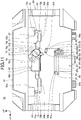
- Fig. 4 is a front elevation view of an internal structure of a rear surface portion of the case 60.
- the case 60 includes a case main body 63 and a rear surface cover 64.
- the case main body 63 includes the storage space.
- the rear surface cover 64 covers a rear surface 63a of the case main body 63 from the rear.
- Fig. 4 depicts a condition, in which the rear surface cover 64 depicted in Fig. 3 has been removed.
- a key cylinder 66 and a fixing operator 67 are disposed on the rear surface portion of the case 60.
- the key cylinder 66 is a rotary operator that is rotationally operated by a key 65.
- the fixing operator 67 operates for fixing of the storage member 52 with respect to the mounting base 51 and for releasing the fixing of the storage member 52 with respect to the mounting base 51.
- a lid operator 68 and an operating knob 75 are disposed on the rear surface portion of the case 60.
- the lid operator 68 operates to open or close the lid 61.
- the operating knob 75 is an open/close control mechanism that imposes or releases restriction on opening or closing of the lid 61 by the lid operator 68.
- the key cylinder 66, the fixing operator 67, the lid operator 68, and the operating knob 75 are disposed to be exposed on the rear surface cover 64.
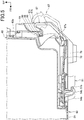
- Fig. 5 is a cross-sectional view taken along line V-V in Fig. 3 . With the rear surface cover 64, Fig. 5 depicts only a lower portion thereof.
- the fixing operator 67 is an operating lever that operates the movable engagement portion 54b of the lower surface 54.
- the fixing operator 67 is disposed at a central portion in the vehicle width at the lower portion of the rear surface portion of the case 60.
- the fixing operator 67 is supported in the rear surface portion of the case 60 by a shaft portion 67a, which extends in the vehicle width direction (left-right direction).
- the shaft portion 67a is disposed at a lower portion of the fixing operator 67.
- the fixing operator 67 is rotatable in a vertical direction about the shaft portion 67a.
- the fixing operator 67 includes a holding portion 67b at an upper portion thereof.
- the holding portion 67b is held by a user during operation.
- the fixing operator 67 further has an engagement recessed portion 67c at a portion anterior to the holding portion 67b in an upper surface portion of the fixing operator 67.
- the engagement recessed portion 67c is recessed inferiorly.
- the engagement recessed portion 67c is located inside the rear surface cover 64 and inferior to an upper end of the holding portion 67b.
- the engagement recessed portion 67c has a groove shape extending in the vehicle width direction.
- the fixing operator 67 is connected with the movable engagement portion 54b via a connection rod 70.
- the connection rod 70 extends in the vehicle fore-aft direction through a path at the lower portion of the case 60.
- the connection rod 70 has a rear end connected with a lower end portion of the fixing operator 67 at a position inferior to the shaft portion 67a.
- the connection rod 70 has a front end connected with a rear portion of the movable engagement portion 54b.
- the fixing operator 67 operates for fixing of the storage member 52 with respect to the mounting base 51 and for releasing the fixing of the storage member 52 with respect to the mounting base 51. Under the condition in which the fixing operator 67 is operated for releasing the fixing, the storage member 52 can be pulled up and removed from the mounting base 51.
- a lid open/close mechanism 71 for opening or closing the lid 61 is disposed at an upper portion of the rear surface portion of the storage member 52.
- the lid open/close mechanism 71 includes the lid operator 68, a link member 72, a pair of left and right engagement members 73, a pair of left and right urging members 74, and a pair of left and right engaged portions 61a.
- the link member 72 is moved in the vehicle width direction through an operation of the lid operator 68.
- the engagement members 73 are connected with the link member 72.
- the urging members 74 urge the engagement members 73.
- the engaged portions 61a are disposed in the lid 61.
- Fig. 6 is a perspective view of the lid open/close mechanism 71, as viewed from a posterior side.
- Fig. 7 is a cross-sectional view taken along line VII-VII in Fig. 4 .
- the lid operator 68 is disposed at a central portion in the vehicle width direction at the upper portion of the rear surface portion of the case 60.
- the lid operator 68 is located superior to the fixing operator 67.
- the lid operator 68 is supported on the rear surface portion of the case 60 by a shaft portion 68a, which extends in the vertical direction.
- the shaft portion 68a is disposed at a first end portion (left end portion) in the vehicle width direction of the lid operator 68.
- the lid operator 68 is rotatable in the vehicle width direction about the shaft portion 68a.
- the lid operator 68 includes a depression portion 68b at the first end portion in the vehicle width direction.
- the depression portion 68b has a columnar shape protruding anteriorly.
- the lid operator 68 further has a recessed portion 68c at a second end portion (right end portion) in the vehicle width direction.
- the recessed portion 68c is recessed in the vehicle width direction.
- the recessed portion 68c has a groove shape extending in the vertical direction.
- the link member 72 is a bar-shaped member extending in the vehicle width direction.
- the link member 72 is disposed anterior to the lid operator 68.
- the lid operator 68 overlaps a central portion in the vehicle width direction of the link member 72 from the rear.
- the link member 72 extends to a first side and a second side in the vehicle width direction with respect to the lid operator 68.
- the link member 72 has an opening 72a at a portion at which the lid operator 68 overlaps.
- the depression portion 68b of the lid operator 68 is passed through the opening 72a.
- the opening 72a has a depressed portion 72b on an inner peripheral surface thereof.
- the depressed portion 72b is depressed by the depression portion 68b, which moves in the vehicle width direction.
- the opening 72a further has a clearance portion 72c.
- the clearance portion 72c is formed on an opposite side of the depression portion 68b from the depressed portion 72b.
- the clearance portion 72c is recessed in the vehicle width direction so as to clear the depression portion 68b.
- the case main body 63 has a pair of upper and lower guide walls 63b ( Fig. 4 ).
- the guide walls 63b protrude posteriorly from the rear surface 63a.
- the guide walls 63b are also provided in pairs disposed laterally across the lid operator 68.
- the link member 72 is supported so as to be sandwiched between the upper and lower guide walls 63b and is movable in the vehicle width direction along the guide walls 63b.
- the left and right engagement members 73 are connected with a first end portion and a second end portion in the vehicle width direction, respectively, of the link member 72.
- the engagement members 73 each include a rotational shaft 73a at a vertically intermediate portion.
- the rotational shaft 73a extends in the fore-aft direction.
- the engagement member 73 is supported on the rear surface portion of the case 60 via the rotational shaft 73a.
- the engagement member 73 is rotatably connected with an end portion in the vehicle width direction of the link member 72 via a connection shaft 73b.
- the connection shaft 73b is disposed at a lower end portion of the engagement member 73.
- the connection shaft 73b extends in parallel with the rotational shaft 73a.
- the engagement member 73 includes a hook portion 73c at an upper end portion thereof.
- the hook portion 73c protrudes to a second side (right-hand side) in the vehicle width direction.
- the engagement member 73 further includes an inclined portion 73d.
- the inclined portion 73d is disposed at an upper edge of the hook portion 73c and has a height decreasing toward a distal end side thereof.
- a pair of left and right box-shaped portions 63c is disposed at an upper portion of the rear surface 63a of the case main body 63.
- the box-shaped portions 63c bulge posteriorly.
- the box-shaped portions 63c each have a box shape having an upper surface and a lower surface opening in the vertical direction. In Fig. 4 , the box-shaped portions 63c are partially cut away to reveal the interior.
- the engagement member 73 is passed from below through the box-shaped portion 63c and an upper portion of the engagement member 73 is housed inside the box-shaped portion 63c.
- the engagement member 73 is housed in the box-shaped portion 63c and located inferior to an upper surface of the case main body 63.
- the engagement member 73 does not protrude superiorly from the case main body 63, which enhances ease of use of the storage member 52.
- the engagement member 73 further includes a protrusion 73e and a stopper 73f.
- the protrusion 73e and the stopper 73f are formed at an upper portion of the engagement member 73 on a side opposite from the hook portion 73c.
- the urging members 74 are each a coil spring that extends in the vehicle width direction and are each housed in the box-shaped portion 63c.
- the urging member 74 has a first end supported by the protrusion 73e and a second end supported by an inner surface of a side surface portion of the box-shaped portion 63c.
- the stopper 73f is disposed inferior to the protrusion 73e and protrudes in the vehicle width direction.
- the stopper 73f abuts against a receiver portion (not depicted) disposed near the stopper 73f to thereby restrict a rotational angle of the engagement member 73 to a predetermined angle.
- the left and right engaged portions 61a of the lid 61 extend inferiorly from a lower surface of a rear end portion of the lid 61 and engage the engagement members 73.
- the engaged portions 61a each include front and rear support walls 61b (the front support wall 61b is not depicted) and an engagement pin 61c.
- the front and rear support walls 61b are juxtaposed in the fore-aft direction to extend inferiorly from the lower surface of the lid 61.
- the engagement pin 61c connects lower end portions of the front and rear support walls 61b in the fore-aft direction.
- the urging member 74 urges the hook portion 73c in a direction in which the hook portion 73c engages the engagement pin 61c.
- Fig. 6 When the lid operator 68 is rotated posteriorly, the depression portion 68b ( Fig. 7 ) of the lid operator 68 is moved toward the second side (right-hand side) in the vehicle width direction to thereby depress the depressed portion 72b on the inner surface of the opening 72a in the link member 72.
- the depressed link member 72 is slid toward the second side (right-hand side) in the vehicle width direction as depicted in Fig. 7 , so that the engagement members 73, which are connected with the end portions of the link member 72, resist urging forces of the urging members 74 to thereby rotate about the rotational shafts 73a.
- the urging members 74 rotate such that the hook portions 73c leave the engagement pins 61c. This releases the engagement between the engagement members 73 and the engaged portions 61a, thus allowing the lid 61 to be opened.
- Fig. 8 is a front elevation view of a structure of the operating knob 75 and components therearound, as viewed from a posterior side. Fig. 8 omits depicting the link member 72.
- the operating knob 75 is an operator that is rotated.
- the operating knob 75 is disposed beside the recessed portion 68c in the lid operator 68 and posterior to the link member 72.
- the operating knob 75 is located superior to the key cylinder 66.
- the operating knob 75 includes a knob main body 76, a rotational shaft 77, a lid operation restriction portion 78, and a stopper portion 79.
- the knob main body 76 has a circular shape.
- the rotational shaft 77 is disposed at a central portion of a front surface of the knob main body 76 and extends in the vehicle fore-aft direction.
- the lid operation restriction portion 78 extends to the outside in a radial direction of the knob main body 76.
- the stopper portion 79 extends from a position different from a position, from which the lid operation restriction portion 78 extends, to the outside in the radial direction of the knob main body 76.
- the lid operation restriction portion 78 and the stopper portion 79 are disposed in a space between the rear surface 63a of the case main body 63 and the rear surface cover 64.
- the operating knob 75 is supported by the rear surface cover 64 ( Fig. 3 ) via the rotational shaft 77 and rotatable about the rotational shaft 77.
- a pinching portion 76a which protrudes so as to allow the user to pinch for operation, is disposed on a rear surface of the knob main body 76.
- Fig. 9 is a perspective view of the operating knob 75, as viewed from an anterior side. It is noted that Fig. 9 omits depicting the lid operation restriction portion 78 and the stopper portion 79.
- a disc-shaped plate 80 is disposed between the knob main body 76 and the rear surface cover 64 ( Fig. 3 ).
- the plate 80 is fixed onto the rear surface cover 64.
- the plate 80 has a hole 80a, a pair of engagement holes 80b and 80c, and a position restriction hole 80d.
- the rotational shaft 77 of the operating knob 75 is passed through the hole 80a.
- the engagement holes 80b and 80c are spaced apart from each other in a circumferential direction of the operating knob 75.
- the position restriction hole 80d has a slot shape extending along the circumferential direction of the operating knob 75.
- the knob main body 76 includes a ball 81 and a protruding portion 82, which are disposed on a front surface portion thereof.
- the ball 81 engages from the rear either one of the engagement holes 80b and 80c in the plate 80.
- the protruding portion 82 is passed through the position restriction hole 80d from the rear.
- a rotational range through which the operating knob 75 is rotated is restricted by the protruding portion 82 moving in the circumferential direction through rotation of the operating knob 75 and abutting against an end in the position restriction hole 80d.
- the rotational range through which the operating knob 75 is rotated is, for example, 45 degrees.
- the ball 81 is housed in the hole portion in the front surface portion of the knob main body 76 and is pressed up against the plate 80 by a spring disposed at the hole portion.
- an urging force of the spring causes the ball 81 to engage either one of the engagement holes 80b and 80c. This allows the user to hear a click during rotation of the operating knob 75, offering operability for the user.
- the lid operation restriction portion 78 of the operating knob 75 extends from the side of the knob main body 76 in the vehicle width direction and engages the recessed portion 68c in the lid operator 68. Under the foregoing condition, the lid operation restriction portion 78 of the operating knob 75 abuts on the recessed portion 68c in the lid operator 68, so that the lid operator 68 cannot be rotated from the condition depicted in Figs. 4 and 8 to the posterior side. It is noted that the lid operation restriction portion 78 is required only to abut on the recessed portion 68c to thereby restrict rotation of the lid operator 68 when the lid operator 68 is to be rotated. Specifically, the lid operation restriction portion 78 is not necessarily required to abut on the recessed portion 68c at all times.
- the operating knob 75 restricts an open/close operation for the lid 61 by the lid operator 68.
- Fig. 8 depicts, with an imaginary line, a condition in which the restriction of the open/close operation for the lid 61 by the operating knob 75 is released.
- the lid operation restriction portion 78 moves out of the recessed portion 68c in the lid operator 68, so that engagement between the lid operation restriction portion 78 and the recessed portion 68c is released.
- the lid operator 68 can be rotated toward the posterior side from the condition depicted in Fig. 8 , so that the user can operate the lid operator 68 to open the lid 61.
- the key cylinder 66 is disposed such that a key hole 66a, in which the key 65 is inserted, faces posteriorly.
- the key cylinder 66 has an axis of a rotational operation by the key 65 extending in the vehicle fore-aft direction.
- the key cylinder 66 is disposed beside the fixing operator 67 and inferior to the operating knob 75.
- the key cylinder 66 includes a first link connection portion 66b and a second link connection portion 66c.
- the first link connection portion 66b and the second link connection portion 66c are rotated integrally with the key 65, which is inserted in the key hole 66a and operated.
- the first link connection portion 66b and the second link connection portion 66c are rotated about the axis of the key cylinder 66.
- first link connection portion 66b extends superiorly relative to the key cylinder 66 and the second link connection portion 66c extends in the vehicle width direction toward the fixing operator 67.
- a first link mechanism 85 (open/close control mechanism operation restriction portion) and a second link mechanism 86 are connected with the key cylinder 66.
- the first link mechanism 85 extends from the key cylinder 66 toward the operating knob 75.
- the second link mechanism 86 extends from the key cylinder 66 in the vehicle width direction toward the fixing operator 67.
- the first link mechanism 85 includes a first link rod 87 and a first oscillation link 88.
- the first link rod 87 extends from the first link connection portion 66b of the key cylinder 66 superiorly.
- the first oscillation link 88 is connected with an upper end portion of the first link rod 87.
- the first link rod 87 is a linearly and vertically extending rod.
- the first link rod 87 has a lower end portion connected with the first link connection portion 66b via a connection shaft 87a, which extends in the fore-aft direction.
- the first link rod 87 is rotatable about the connection shaft 87a.
- the first oscillation link 88 has a plate shape extending vertically.
- the first oscillation link 88 is shorter in vertical length than the first link rod 87.
- the first oscillation link 88 has an upper end portion connected with an upper end portion of the first link rod 87 via a connection shaft 87b, which extends in the fore-aft direction.
- the first oscillation link 88 is rotatable with respect to the first link rod 87 about the connection shaft 87b.
- the first oscillation link 88 has a lower end portion connected with the rear surface portion of the case 60 via a case connection shaft 88a, which extends in the fore-aft direction.
- the case connection shaft 88a is disposed inferior to the connection shaft 87b.
- the case connection shaft 88a is fixed to an inner surface of the rear surface cover 64 ( Fig. 3 ).
- the first oscillation link 88 is oscillatable about the case connection shaft 88a.
- the stopper portion 79 of the operating knob 75 extends inferiorly with respect to the knob main body 76.
- the first oscillation link 88 is disposed inferior to the stopper portion 79 and the upper end portion of the first oscillation link 88 is close to the stopper portion 79.
- the first link mechanism 85 restricts a rotational operation of the operating knob 75 by the first oscillation link 88 abutting on the stopper portion 79 of the operating knob 75. It is noted that, in this case, the first oscillation link 88 is required only to abut on the stopper portion 79 to thereby restrict rotation of the operating knob 75 when the operating knob 75 is to be rotated. The first oscillation link 88 is not necessarily required to contact the engagement recessed portion 67c at all times.
- the stopper portion 79 includes a first abutment portion 79a and a second abutment portion 79b (movement restriction portion).
- the first abutment portion 79a and the second abutment portion 79b protrude anteriorly from the lower end portion of the stopper portion 79.
- the second abutment portion 79b is disposed outside the first abutment portion 79a in the vehicle width direction.
- the second link mechanism 86 includes a second link rod 90 and a second oscillation link 91.
- the second link rod 90 extends from the second link connection portion 66c of the key cylinder 66 in the vehicle width direction.
- the second oscillation link 91 is connected with an outer end portion in the vehicle width direction of the second link rod 90.
- the second link rod 90 is a rod that extends linearly and substantially horizontally in the vehicle width direction.
- the second link rod 90 has an inner end portion in the vehicle width direction connected with the second link connection portion 66c via a connection shaft 90a, which extends in the fore-aft direction.
- the second link rod 90 is rotatable about the connection shaft 90a.
- the second oscillation link 91 has a plate shape extending in the vehicle width direction.
- the second oscillation link 91 is shorter in length in the vehicle width direction than the second link rod 90.
- the second oscillation link 91 has an outer end portion in the vehicle width direction connected with the outer end portion in the vehicle width direction of the second link rod 90 via a connection shaft 90b, which extends in the fore-aft direction.
- the second oscillation link 91 is rotatable with respect to the second link rod 90 about the connection shaft 90b.
- the second oscillation link 91 has an inner end portion in the vehicle width direction connected with the rear surface portion of the case 60 via a case connection shaft 91a, which extends in the fore-aft direction.
- the case connection shaft 91a is disposed inside the connection shaft 90b in the vehicle width direction. More specifically, the case connection shaft 91a is fixed to the inner surface of the rear surface cover 64 ( Fig. 3 ).
- the second oscillation link 91 is oscillatable about the case connection shaft 91a.
- the fixing operator 67 has the upper portion overlapping the second link rod 90 from the rear to thereby cover the second link rod 90.
- the second link rod 90 is located anterior to the upper portion of the fixing operator 67 and extends from the second link connection portion 66c of the key cylinder 66 across the fixing operator 67 in the vehicle width direction before being connected with the second oscillation link 91.
- the second oscillation link 91 is disposed on the first side in the vehicle width direction with respect to the fixing operator 67.
- the key cylinder 66 is disposed on the second side in the vehicle width direction with respect to the fixing operator 67.
- the second link rod 90 is located immediately above the engagement recessed portion 67c in the fixing operator 67 and can engage the engagement recessed portion 67c.
- the second link rod 90 abuts against the fixing operator 67 via the engagement recessed portion 67c to thereby restrict the operation of the fixing operator 67. It is here noted that the second link rod 90 is required only to abut against the engagement recessed portion 67c to thereby restrict rotation of the operating knob 75 when the fixing operator 67 is to be rotated toward the rear.
- the second link rod 90 is not necessarily required to be in contact with the engagement recessed portion 67c at all times.
- the key cylinder 66 is in a "locked state" in which fixing of the storage member 52 with respect to the mounting base 51 of the rear carrier 50 is locked.
- the key hole 66a extends substantially vertically.
- the second link rod 90 engages the engagement recessed portion 67c in the fixing operator 67 and thus the operation of the fixing operator 67 is restricted.
- the user is unable to bring the fixing operator 67 into the state of releasing the fixing and the storage member 52 is maintained in the condition of being fixed to the mounting base 51.
- the “locked state” represents a state in which the fixing of the storage member 52 with respect to the mounting base 51 is locked through the operation of the key cylinder 66 by the key 65.
- the first oscillation link 88 of the first link mechanism 85 is located on a trajectory 79c ( Fig. 8 ) of rotation of the stopper portion 79 during a rotational operation of the operating knob 75, thereby restricting the rotational operation of the operating knob 75.
- the lid operation restriction portion 78 of the operating knob 75 engages the recessed portion 68c in the lid operator 68, so that an operation to open or close the lid 61 by the lid operator 68 is restricted.
- the first oscillation link 88 is located inside the stopper portion 79 in the vehicle width direction and abuts against the first abutment portion 79a of the stopper portion 79. Thereby, a rotational operation of the operating knob 75 is restricted in the direction in which the restriction on opening or closing of the lid 61 by the lid operator 68 is released.
- Fig. 10 is a front elevation view of a condition of the key cylinder 66 operated from the state depicted in Fig. 4 into an "unlocked state.”
- the key cylinder 66 is in the "unlocked state" in which fixing of the storage member 52 with respect to the mounting base 51 of the rear carrier 50 is unlocked.
- the key cylinder 66 is rotated clockwise by approximately 90 degrees in Fig. 4 by the key 65, so that the key hole 66a extends substantially horizontally. It is noted that, when the key 65 is removed from the key hole 66a, the key cylinder 66 cannot be rotated.
- the second link connection portion 66c of the key cylinder 66 is rotated clockwise approximately 90 degrees from the condition depicted in Fig. 4 about an axis of the key cylinder 66.
- the second link rod 90 leaves the engagement recessed portion 67c ( Fig.
- the "unlocked state” represents a state in which the fixing of the storage member 52 with respect to the mounting base 51 is unlocked through the operation of the key cylinder 66 by the key 65.
- the first link connection portion 66b of the key cylinder 66 is rotated clockwise approximately 90 degrees from the condition depicted in Fig. 4 about the axis of the key cylinder 66.
- the first oscillation link 88 moves from a position on the trajectory 79c ( Fig. 8 ) of rotation of the stopper portion 79 of the operating knob 75 inferiorly, to be off the trajectory 79c.
- the operating knob 75 can now be rotated.
- the state of restriction on the operation of the operating knob 75 by the first oscillation link 88 is switched so as to be operatively associated with the operation of the key cylinder 66 that switches between the "locked state” and the “unlocked state.”
- the state of restriction on the operation of the operating knob 75 is switched in response to the operation of the key cylinder 66.
- the user can operate both the fixing operator 67 and the operating knob 75.
- Fig. 11 is a front elevation view of a condition, in which the operating knob 75 is rotated from the state depicted in Fig. 10 in a direction in which restriction of the operation of the lid operator 68 is released.
- the operating knob 75 is rotated clockwise approximately 45 degrees from the condition depicted in Fig. 10 and the engagement between the lid operation restriction portion 78 of the operating knob 75 and the recessed portion 68c in the lid operator 68 is released. This releases the restriction on the opening or closing of the lid 61 by the lid operator 68, so that the user can operate the lid operator 68 to open the lid 61.
- the "unlocked state" is established in the condition depicted in Fig. 11 and the user can operate the fixing operator 67.
- Fig. 12 is a front elevation view of the "locked state" as switched from the state depicted in Fig. 11 .
- Fig. 12 the key 65 is operated from the condition depicted in Fig. 11 to rotate the key cylinder 66 counterclockwise approximately 90 degrees and the key cylinder 66 is placed in the "locked state.” In the "locked state,” the user can remove the key 65 from the key cylinder 66.
- the first oscillation link 88 of the first link mechanism 85 is located on the trajectory 79c ( Fig. 8 ) of rotation of the stopper portion 79 of the operating knob 75 and the rotational operation of the operating knob 75 is restricted.
- the first oscillation link 88 is located at a position outside in the vehicle width direction with respect to the stopper portion 79 and abuts against the second abutment portion 79b of the stopper portion 79, so that the rotational operation of the operating knob 75 is restricted in a direction in which the operation to open or close the lid 61 by the lid operator 68 is restricted.
- a condition is maintained in which the restriction on the opening or closing of the lid 61 by the lid operator 68 is released, so that the user can operate the lid operator 68 to open the lid 61.
- the restriction on the opening or closing of the lid 61 by the lid operator 68 is released as depicted in Fig. 12 , the user can open the lid 61 by simply operating the lid operator 68 without the need to operate the key cylinder 66 with the key 65.
- the user when the storage member 52 is in the condition depicted in Fig. 12 , the user can maintain a condition in which fixing of the storage member 52 onto the vehicle body side is locked and can open the lid 61 by simply operating the lid operator 68 without the need to operate the key cylinder 66 with the key 65.
- the user when needing to open or close the lid 61 frequently or when leaving the motorcycle 1 for a brief period of time, the user can open or close the lid 61 without the use of the key 65 by simply placing the storage member 52 in the condition depicted in Fig. 12 . Convenience of the storage member 52 is thus enhanced.
- the lid operator 68 When the key 65 functions also as a main key that switches on or off main power of the motorcycle 1, simply operating the lid operator 68 enables the lid 61 to be opened without the need to remove the main key (key 65) from the motorcycle 1. This eliminates the need to remove the main key from the motorcycle 1 before the lid 61 can be opened. Thus, the lid operator 68 can be operated to open the lid 61 even when, for example, the engine 11 is left running.
- the user can bring the storage member 52 into the condition depicted in Fig. 4 .
- the user can use the key 65 to place the key cylinder 66 into the "unlocked state" from the condition depicted in Fig. 4 and release the restriction by the operating knob 75 on the opening or closing of the lid 61 before operating the lid operator 68 to open the lid 61.
- Fig. 13 is a front elevation view of a condition, in which the lid operator 68 is operated under the condition depicted in Fig. 12 .
- the lid operator 68 When the lid operator 68 is operated under the condition depicted in Fig. 12 , the depressed portion 72b is pushed in the vehicle width direction by the depression portion 68b ( Fig. 7 ) of the lid operator 68 and the link member 72 slides in the vehicle width direction in a direction indicated by a symbol A. As a result, the left and right engagement members 73 each rotate about the rotational shaft 73a, so that the engagement between the hook portion 73c and the engagement pin 61c of the lid 61 is released and the lid 61 is opened.
- the lid 61 is raised superiorly by a reaction force of a sealing member (not depicted) that is disposed between the peripheral edge portion of the upper surface of the case 60 and the lid 61.
- the user depresses the lid 61 inferiorly to thereby cause the engagement pins 61c of the lid 61 to engage the hook portions 73c of the engagement members 73.
- the engagement pins 61c depress the inclined portions 73d of the hook portions 73c from above, which causes the engagement members 73 to resist the urging forces of the urging members 74 and rotate.
- the link member 72 which is connected with the engagement members 73, slides in the vehicle width direction in the direction of the arrow A.
- the opening 72a in the link member 72 through which the depression portion 68b of the lid operator 68 is passed, has the clearance portion 72c on the opposite side of the depression portion 68b from the depressed portion 72b.
- the clearance portion 72c is recessed in the vehicle width direction so as to clear the depression portion 68b. This configuration allows an inner peripheral surface of the opening 72a to avoid contact with a side surface portion of the depression portion 68b because of a space available from the clearance portion 72c even when the link member 72 is slid in the direction of the arrow A by the force to depress the lid 61 when the lid 61 is to be closed.
- the force acting from the lid 61 on the engagement members 73 and the link member 72 is not transmitted to the lid operator 68 when the lid 61 is closed because of the presence of the clearance portion 72c. This eliminates the need to thrust the lid operator 68 aside when the lid 61 is to be closed, so that the lid 61 can be closed with a small force.
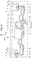
- Fig. 14 is a perspective view of the lid open/close mechanism 71, the operating knob 75, the first link mechanism 85, and components therearound, as viewed from a posterior side.
- Fig. 14 depicts a condition, in which the key cylinder 66 is in the "locked state" as in Fig. 4 , the operating knob 75 restricts operation of the lid operator 68, and the lid 61 is open.
- An engagement portion 72d which is recessed superiorly, is provided in a lower surface portion of the link member 72 of the lid open/close mechanism 71.
- the second abutment portion 79b of the stopper portion 79 of the operating knob 75 engages the engagement portion 72d of the link member 72 from below.
- the abutment of the stopper portion 79 with respect to the link member 72 restricts a motion of the link member 72 sliding in the vehicle width direction.
- the second abutment portion 79b serves as a movement restriction portion that restricts the sliding motion of the link member 72.
- the second abutment portion 79b is required only to abut against the engagement portion 72d to thereby restrict the sliding motion of the link member 72 when the link member 72 is to make the sliding motion and the second abutment portion 79b is not necessarily required to be in contact the engagement portion 72d at all times.
- the stopper portion 79 of the operating knob 75 is spaced inferiorly apart from the engagement portion 72d of the link member 72 and the engagement between the second abutment portion 79b and the engagement portion 72d of the link member 72 is released. Under this condition, the link member 72 can slide.
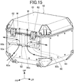
- Fig. 15 is a perspective view of the storage member 52, as viewed from an anterior side.
- a backrest 92 is provided on a front surface 60a of the case 60 of the storage member 52.
- the backrest 92 serves as a support for a back of the passenger seated in the rear seat 14b.
- the backrest 92 is formed of an elastic member offering a cushioning property.
- the backrest 92 is a rectangular plate-shaped member having a length longer in the vehicle width direction than in the vertical direction.
- the backrest 92 is mounted at an upper portion of the front surface 60a such that a wall thickness direction thereof is oriented toward the vehicle fore-aft direction.
- the backrest 92 has an airflow path 93.
- the airflow path 93 allows air through the motorcycle 1 to flow through the inside of the backrest 92.
- the airflow path 93 includes a pair of left and right vertical airflow passages 93a.
- the vertical airflow passages 93a each pass through the backrest 92 from an upper surface to a lower surface thereof.
- the vertical airflow passages 93a are disposed at a central portion in the vehicle width direction of the backrest 92.
- the airflow path 93 further includes a pair of lateral airflow passages 93b.
- the lateral airflow passages 93b each extend from a vertical intermediate portion of each of the vertical airflow passages 93a toward the outside in the vehicle width direction, thus communicating with a corresponding outer side of the backrest 92.
- part of airflows W flowing over the front surface 60a of the storage member 52 and therearound flows vertically through the vertical airflow passages 93a and flows from the vertical airflow passages 93a to the lateral airflow passages 93b onto the outside in the vehicle width direction.
- the airflows W can thereby smoothly flow on the side of the front surface 60a of the storage member 52, so that riding performance of the motorcycle 1 can be enhanced.
- the airflow path 93 can ensure a smooth flow of the airflows W.
- the front surface 60a of the storage member 52 is thus flatly shaped to provide a large capacity of the storage member 52.
- Fig. 16 is a perspective view of the mounting base 51 and a second storage member 152, which is different from the storage member 52.
- the second storage member 152 includes a claw-shaped engagement portion 154a at a center in the vehicle width direction at a front portion on a lower surface of the second storage member 152.
- the engagement portion 154a protrudes anteriorly.
- the second storage member 152 further includes a claw-shaped movable engagement portion 154b at a central portion in the vehicle width direction on the lower surface of the second storage member 152.
- the movable engagement portion 154b protrudes posteriorly.
- the movable engagement portion 154b is located posterior to the engagement portion 154a and is slidable in the vehicle fore-aft direction by an operation by the user.
- the second storage member 152 is placed on the upper surface of the mounting base 51 and fixed to the mounting base 51 by the engagement portion 154a engaging the central engagement hole 51c and the movable engagement portion 154b engaging the rear portion engagement hole 51b.
- the use of the central engagement hole 51c enables the second storage member 152, which is different from the storage member 52, to be mounted on the mounting base 51.
- the storage unit structure for the motorcycle 1 includes the box-shaped storage member 52, which is removably mounted on the rear carrier 50 on the vehicle body side, and the key cylinder 66, which is disposed in the storage member 52 and rotationally operated.
- the locked state and the unlocked state of the storage member 52 with respect to the rear carrier 50 are switched through the operation of the key cylinder 66.
- the storage unit structure includes: the lid operator 68, which operates to open or close the lid 61 of the storage member 52; the operating knob 75, which serves as the open/close control mechanism that imposes or releases the restriction on the opening or closing of the lid 61 by the lid operator 68; and the first link mechanism 85, which serves as the open/close control mechanism operation restriction portion that imposes or releases restriction on the operation of the operating knob 75.
- the state of restriction on the operation of the operating knob 75 by the first link mechanism 85 is switched in response to the operation of the key cylinder 66.
- the state of restriction on the operating knob 75 by the first link mechanism 85 is switched in response to the operation of the key cylinder 66. This, for example, eliminates the need for a rotary operator dedicated to switching of the state of restriction on the operating knob 75. This contributes to a simplified structure.
- the first link mechanism 85 restricts the operation of the operating knob 75.
- the first link mechanism 85 releases the restriction on the operation of the operating knob 75.
- the operation of the operating knob 75 is restricted when the storage member 52 is in the "locked state” and the restriction on the operation of the operating knob 75 is released when the storage member 52 is in the "unlocked state.”
- the user can intuitively operate the "locked state” of the storage member 52 and the operating knob 75 and gains operability.
- the operating knob 75 is rotationally operated, the operating knob 75 includes the lid operation restriction portion 78 that restricts the operation by the lid operator 68, and the rotational operation of the operating knob 75 is restricted by the stopper portion 79 provided in the operating knob 75 abutting on the first link mechanism 85.
- the opening or closing of the lid 61 by the lid operator 68 can be restricted by a simple structure of the lid operation restriction portion 78 of the rotationally operated operating knob 75. Additionally, the rotational operation of the operating knob 75 can be restricted by a simple structure of the first link mechanism 85 being brought into abutment with the stopper portion 79 of the operating knob 75.
- the operation restriction portion is the first link mechanism 85 that extends from the key cylinder 66, and the first link mechanism 85 moves with an operation of the key cylinder 66 to thereby impose or release restriction on the operation of the operating knob 75.
- the restriction on the operation of the operating knob 75 can be imposed or released by a simple structure of the first link mechanism 85 that moves with the operation of the key cylinder 66.
- first link mechanism 85 extends from the key cylinder 66 superiorly toward the operating knob 75.
- the first link mechanism 85 can be compactly provided.
- the storage unit structure further includes: the fixing operator 67 that operates for fixing of the storage member 52 with respect to the mounting base 51 and for releasing the fixing of the storage member 52 with respect to the mounting base 51, restriction on the operation of the fixing operator 67 being imposed in the "locked state” and the restriction on the operation of the fixing operator 67 being released in the "unlocked state”; and the second link mechanism 86 that extends from the key cylinder 66, the second link mechanism 86 moving through the operation of the key cylinder 66.
- the second link mechanism 86 imposes restriction on the operation of the fixing operator 67 in the "locked state” and leaves the fixing operator 67 to thereby release the restriction on the operation of the fixing operator 67 in the "unlocked state.”
- the second link mechanism 86 extends from the key cylinder 66 in the vehicle width direction toward the fixing operator 67.
- the second link mechanism 86 can be compactly provided.
- the storage unit structure further includes the engagement member 73 that engages the engaged portion 61a of the lid 61 to thereby maintain the lid 61 in a closed position; and the link member 72 connected with the engagement member 73 and disposed to be movable in the vehicle width direction.
- the link member 72 is moved through the operation of the lid operator 68, the engagement member 73 moves to thereby release the engagement between the engaged portion 61a and the engagement member 73.
- the link member 72 is moved by the operation of the lid operator 68, which moves the engagement member 73 to thereby release the engagement between the engaged portion 61a of the lid 61 and the engagement member 73.
- the lid 61 can be operated to be opened or closed through a simple structure.
- the storage member 52 includes the case 60 and the lid 61 that closes the opening in the upper surface of the case 60, and the engagement member 73 is disposed on the side of the case 60 and at least a part of the engagement member 73 is housed in the case 60.
- the engagement member 73 can be prevented from protruding toward the lid 61 side, which enhances ease of use of the storage member 52. It is noted that, while the engagement member 73 is generally housed in the case 60 in the embodiment, an upper end portion of the engagement member 73 may protrude superiorly from the case 60.
- the engagement member 73 is urged by the urging member 74 in the direction in which the engagement member 73 engages the engaged portion 61a, the lid operator 68 depresses the link member 72 via the depression portion 68b to thereby resist the urging force of the urging member 74 and move the engagement member 73 via the link member 72, and the link member 72 has the clearance portion 72c to clear the depression portion 68b that moves when the engaged portion 61a is engaged by the engagement member 73 and the lid 61 is closed.
- the clearance portion 72c of the link member 72 can clear the engaged portion 61a, which is moved when the engaged portion 61a is engaged by the engagement member 73 and the lid 61 is closed, so that the movement of the link member 72 operatively associated with the engagement member 73 is not transmitted to the lid operator 68.
- the lid 61 can be closed even with a small force.
- the operating knob 75 includes the second abutment portion 79b that can engage the link member 72, and, under a condition in which restriction on opening or closing of the lid 61 by the lid operator 68 is released, the operating knob 75 is spaced away from the link member 72 and, under a condition in which the restriction on the opening or closing of the lid 61 by the lid operator 68 is imposed, the second abutment portion 79b engages the link member 72 to thereby restrict movement of the link member 72.
- the backrest 92 for a passenger is disposed on the front surface 60a of the storage member 52.
- the backrest 92 has the airflow path 93 that allows air W to flow through the inside of the backrest 92.
- the air W can smoothly flow through the area around the backrest 92, so that riding performance of the motorcycle 1 can be enhanced.
- the key cylinder 66 which exemplifies the rotary operator that switches between the locked state and the unlocked state of the storage member 52 with respect to the vehicle body in the embodiment described above, is illustrative only and not limiting.
- the rotary operator may, for example, be such that restriction on a rotational operation is imposed or released by an authentication system that incorporates a smart key. In this case, communication is performed between the smart key carried by the user and a controller of the motorcycle 1 and, when a signal transmitted by the smart key is authenticated by the controller, restriction on the operation of the rotary operator is released and the rotary operator can now be operated.
- the configuration of the embodiment described above, in which the storage member 52 is mounted via the mounting base 51 on the rear carrier 50 as the vehicle body side, is illustrative only and not limiting.
- the storage member 52 may even be mounted directly on the vehicle body such as the rear carrier.
- the configuration of the embodiment described above, in which the key cylinder 66 imposes or releases restriction on the operation of the fixing operator 67 via the second link mechanism 86, is illustrative only and not limiting.
- a possible arrangement may, for example, be such that an operation of the key cylinder 66 directly operates the movable engagement portion 54b.
- the "locked state" of the storage member 52 means a condition in which the storage member 52 is fixed by the movable engagement portion 54b to the vehicle body and the "unlocked state” of the storage member 52 means a condition in which the fixing of the storage member 52 by the movable engagement portion 54b to the vehicle body is released.
- the saddle riding vehicle which being exemplified by the motorcycle 1 in the embodiment, may still be a three-wheel saddle riding vehicle including two front wheels or two rear wheels, or may even be a saddle riding vehicle including four or more wheels.
- the storage unit structure includes: a lid operator 68 that operates to open or close a lid 61 of the storage member 52; an operating knob 75 that imposes or releases restriction on opening or closing of the lid 61 by the lid operator 68; and a first link mechanism 85 that imposes or releases restriction on the operation of the operating knob 75.
- a state of restriction on the operating knob 75 by the first link mechanism 85 is switched in response to an operation of the key cylinder 66.
Landscapes
- Engineering & Computer Science (AREA)
- Mechanical Engineering (AREA)
- Vehicle Step Arrangements And Article Storage (AREA)
- Lock And Its Accessories (AREA)
Abstract
Description
- The present invention relates to a storage unit structure for a saddle riding vehicle.
- In a storage unit structure for a saddle riding vehicle, in which a box-shaped storage member is removably mounted, a hitherto known device uses a key rotating operation to switch between a locked state and an unlocked state of the storage member with respect to a vehicle body (see, for example, Patent Document 1). In the technique disclosed in
Patent Document 1, the key rotating operation also imposes or releases restriction on opening or closing of a lid for the storage member. - [Patent Document 1]
JP-T-2013-541458 - With the known storage unit structure for a saddle riding vehicle mentioned above, because the locked state of the storage member with respect to the vehicle body and the restriction on opening or closing of the lid for the storage member are simultaneously switched through a single key rotating operation, the restriction on opening or closing of the lid for the storage member cannot be switched solely as required. A possible configuration may, for example, be such that a key operation for the locked state of the storage member with respect to the vehicle body is performed independently of a key operation for the restriction on opening or closing of the lid for the storage member, so that the restriction on opening or closing of the lid for the storage member can be solely performed. This configuration, however, involves a complicated structure.
- The present invention has been made in view of the foregoing situation and it is an object of the present invention to achieve, in a storage unit structure for a saddle riding vehicle, a simple structure for solely switching restriction on opening or closing of a lid for a storage member independently of switching a locked state of the storage member.
- To achieve the foregoing object, a storage unit structure for a saddle riding vehicle, including a box-shaped storage member (52) removably mounted on a side of a vehicle body (50) and a rotary operator (66) that is disposed in the storage member (52) and that is rotationally operated, in which a locked state and an unlocked state of the storage member (52) with respect to the side of the vehicle body (50) are switched through an operation of the rotary operator (66), the storage unit structure including: a lid operator (68) that operates to open or close a lid (61) of the storage member (52); an open/close control mechanism (75) that imposes or releases restriction on opening or closing of the lid (61) by the lid operator (68); and an open/close control mechanism operation restriction portion (85) that imposes or releases restriction on the operation of the open/close control mechanism (75). In the storage unit structure, a state of restriction on the open/close control mechanism (75) by the open/close control mechanism operation restriction portion (85) is switched in response to an operation of the rotary operator (66).
- In the foregoing configuration, preferably, when the storage member (52) is in the locked state through an operation of the rotary operator (66), the open/close control mechanism operation restriction portion (85) restricts an operation of the open/close control mechanism (75), and, when the storage member (52) is in the unlocked state through an operation of the rotary operator (66), the open/close control mechanism operation restriction portion (85) releases restriction on the operation of the open/close control mechanism (75).
- In the foregoing configuration, preferably, the open/close control mechanism (75) includes an operating knob (75) that is rotationally operated, the operating knob (75) includes a lid operation restriction portion (78) that restricts an operation by the lid operator (68), and the rotational operation of the operating knob (75) is restricted by a stopper portion (79) provided in the operating knob (75) abutting on the open/close control mechanism operation restriction portion (85).
- In the foregoing configuration, preferably, the open/close control mechanism operation restriction portion (85) is a first link mechanism (85) that extends from the rotary operator (66), and the first link mechanism (85) moves with an operation of the rotary operator (66) to impose or release restriction on an operation of the open/close control mechanism (75).
- In the foregoing configuration, preferably, the first link mechanism (85) extends from the rotary operator (66) superiorly toward the open/close control mechanism (75).
- In the foregoing configuration, preferably, the storage unit structure further includes a fixing operator (67) that operates for fixing of the storage member (52) with respect to the side of the vehicle body (50) and for releasing the fixing of the storage member (52) with respect to the side of the vehicle body (50), restriction on an operation of the fixing operator (67) being imposed in the locked state and the restriction on the operation of the fixing operator (67) being released in the unlocked state; and a second link mechanism (86) that extends from the rotary operator (66), the second link mechanism (86) moving through an operation of the rotary operator (66). In the storage unit structure, the second link mechanism (86) imposes restriction on an operation of the fixing operator (67) in the locked state and the second link mechanism (86) leaves the fixing operator (67) to release the restriction on the operation of the fixing operator (67) in the unlocked state.
- In the foregoing configuration, preferably, the second link mechanism (86) extends from the rotary operator (66) in a vehicle width direction toward the fixing operator (67).
- In the foregoing configuration, preferably, the storage unit structure further includes: an engagement member (73) that engages an engaged portion (61a) of the lid (61) to maintain the lid (61) in a closed position; and a link member (72) connected with the engagement member (73) and disposed to be movable in the vehicle width direction. In the storage unit structure, when the link member (72) is moved through an operation of the lid operator (68), the engagement member (73) moves to release engagement between the engaged portion (61a) and the engagement member (73).
- In the foregoing configuration, preferably, the storage member (52) includes a case (60) and the lid (61) that closes an opening in an upper surface of the case (60), and the engagement member (73) is disposed on a side of the case (60) and at least a part of the engagement member (73) is housed in the case (60).
- In the foregoing configuration, preferably, the engagement member (73) is urged by an urging member (74) in a direction in which the engagement member (73) engages the engaged portion (61a), the lid operator (68) depresses the link member (72) via a depression portion (68b) to resist an urging force of the urging member (74) and move the engagement member (73) via the link member (72), and the link member (72) has a clearance portion (72c) to clear the depression portion (68b) that moves when the engaged portion (61a) is engaged by the engagement member (73) and the lid (61) is closed.
- In the foregoing configuration, preferably, the open/close control mechanism (75) includes a movement restriction portion (79b) that can engage the link member (72), and, under a condition in which restriction on opening or closing of the lid (61) by the lid operator (68) is released, the open/close control mechanism (75) is spaced away from the link member (72) and, under a condition in which the restriction on the opening or closing of the lid (61) by the lid operator (68) is imposed, the movement restriction portion (79b) engages the link member (72) to restrict movement of the link member (72).
- In the foregoing configuration, preferably, the storage unit structure further includes a backrest (92) for a passenger, disposed on a front surface (60a) of the storage member (52). In the storage unit structure, the backrest (92) has an airflow path (93) that allows air to flow through an inside of the backrest (92).
- The storage unit structure for a saddle riding vehicle includes the box-shaped storage member that is removably mounted on the vehicle body side and the rotary operator that is disposed in the storage member and that is rotationally operated. The locked state and the unlocked state of the storage member with respect to the vehicle body side are switched through the operation of the rotary operator. The storage unit structure includes: the lid operator that operates to open or close the lid of the storage member; the open/close control mechanism that imposes or releases the restriction on the opening or closing of the lid by the lid operator; and the open/close control mechanism operation restriction portion that imposes or releases restriction on the operation of the operating knob. The state of restriction on the operation of the open/close control mechanism by the open/close control mechanism operation restriction portion is switched in response to the operation of the rotary operator.
- Through the foregoing configuration, under a condition in which the restriction on the operation of the open/close control mechanism by the open/close control mechanism operation restriction portion is released through the operation of the rotary operator, operating the open/close control mechanism allows the restriction on the opening or closing of the lid by the lid operator to be set to be either imposed or released. Thus, only the restriction on the opening or closing of the lid can be switched independently of switching of the locked state of the storage member with respect to the vehicle body side through the operation of the rotary operator. Under a condition in which the restriction on the opening or closing of the lid by the lid operator is released, the lid can be opened or closed without an operation of the rotary operator, which facilitates the operation to open or close the lid. Additionally, the state of restriction on the open/close control mechanism by the open/close control mechanism operation restriction portion is switched in response to the operation of the rotary operator. This, for example, eliminates the need for a rotary operator dedicated to switching of the state of restriction on the open/close control mechanism. This contributes to a simplified structure.
- In the foregoing configuration, when the storage member is in the locked state through the operation of the rotary operator, the open/close control mechanism operation restriction portion may restrict the operation of the open/close control mechanism. When the storage member is in the unlocked state through the operation of the rotary operator, the open/close control mechanism operation restriction portion may release the restriction on the operation of the open/close control mechanism.
- Through the foregoing configuration, the operation of the open/close control mechanism is restricted when the storage member is in the locked state and the restriction on the operation of the open/close control mechanism is released when the storage member is in the unlocked state. The user can intuitively operate the locked state of the storage member and the open/close control mechanism and gains operability.
- In the foregoing configuration, the open/close control mechanism may include the operating knob that is rotationally operated, the operating knob may include the lid operation restriction portion that restricts the operation by the lid operator, and the rotational operation of the operating knob may be restricted by the stopper portion provided in the operating knob abutting on the open/close control mechanism operation restriction portion.
- Through the foregoing configuration, the opening or closing of the lid by the lid operator can be restricted by a simple structure of the lid operation restriction portion of the rotationally operated operating knob. Additionally, the rotational operation of the operating knob can be restricted by a simple structure of the open/close control mechanism operation restriction portion being brought into abutment with the stopper portion of the operating knob.
- In the foregoing configuration, the open/close control mechanism operation restriction portion may be the first link mechanism that extends from the rotary operator, and the first link mechanism may move with an operation of the rotary operator to thereby impose or release restriction on the operation of the open/close control mechanism.
- Through the foregoing configuration, the restriction on the operation of the open/close control mechanism can be imposed or released by a simple structure of the first link mechanism that moves with the operation of the rotary operator.
- Additionally, in the foregoing configuration, the first link mechanism may extend from the rotary operator superiorly toward the open/close control mechanism.
- Through the foregoing configuration, the first link mechanism can be compactly provided.
- In addition, in the foregoing configuration, the storage unit structure may further include: the fixing operator that operates for fixing of the storage member with respect to the vehicle body side and for releasing the fixing of the storage member with respect to the vehicle body side, restriction on the operation of the fixing operator being imposed in the locked state and the restriction on the operation of the fixing operator being released in the unlocked state; and the second link mechanism that extends from the rotary operator, the second link mechanism moving through the operation of the rotary operator. The second link mechanism may impose restriction on the operation of the fixing operator in the locked state and may leave the fixing operator to thereby release the restriction on the operation of the fixing operator in the unlocked state.
- Through the foregoing configuration, the restriction on the operation of the fixing operator can be imposed or released by a simple structure of the second link mechanism that moves through the operation of the rotary operator.
- In the foregoing configuration, the second link mechanism may extend from the rotary operator in the vehicle width direction toward the fixing operator.
- Through the foregoing configuration, the second link mechanism can be compactly provided.
- In the foregoing configuration, the storage unit structure may further include the engagement member that engages the engaged portion of the lid to thereby maintain the lid in a closed position; and the link member connected with the engagement member and disposed to be movable in the vehicle width direction. When the link member is moved through the operation of the lid operator, the engagement member may move to thereby release the engagement between the engaged portion and the engagement member.
- Through the foregoing configuration, the link member is moved by the operation of the lid operator, which moves the engagement member to thereby release the engagement between the engaged portion of the lid and the engagement member. Thus, the lid can be operated to be opened or closed through a simple structure.
- In the foregoing configuration, the storage member includes the case and the lid that closes the opening in the upper surface of the case, and the engagement member is disposed on the side of the case and at least a part of the engagement member is housed in the case.
- Through the foregoing configuration, because at least a part of the engagement member is housed in the case, the engagement member can be prevented from protruding toward the lid side, which enhances ease of use of the storage member.
- In the foregoing configuration, the engagement member may be urged by the urging member in the direction in which the engagement member engages the engaged portion, the lid operator may depress the link member via the depression portion to thereby resist the urging force of the urging member and move the engagement member via the link member, and the link member may have the clearance portion to clear the depression portion that moves when the engaged portion is engaged by the engagement member and the lid is closed.
- Through the foregoing configuration, the clearance portion of the link member can clear the engaged portion that is moved when the engaged portion is engaged by the engagement member and the lid is closed, so that the movement of the link member operatively associated with the engagement member is not transmitted to the lid operator. Thus, the lid can be closed even with a small force.
- In the foregoing configuration, the open/close control mechanism may include the movement restriction portion that can engage the link member, and, under a condition in which restriction on opening or closing of the lid by the lid operator is released, the open/close control mechanism may be spaced away from the link member and, under a condition in which the restriction on the opening or closing of the lid by the lid operator is imposed, the movement restriction portion may engage the link member to thereby restrict movement of the link member.
- Through the foregoing configuration, under the condition in which the restriction on the opening or closing of the lid by the lid operator is imposed by the open/close control mechanism, the movement restriction portion engages the link member and the movement of the link member is restricted, so that the movement of the engagement member is also restricted and the lid cannot be closed. Thus, under the condition in which the restriction on the opening or closing of the lid by the lid operator is imposed by the open/close control mechanism, the lid can be prevented from being closed.
- Additionally, in the foregoing configuration, the backrest for a passenger may be disposed on the front surface of the storage member. The backrest may have the airflow path that allows air to flow through the inside of the backrest.
- Through the foregoing configuration, the air can smoothly flow through the area around the backrest, so that riding performance of a motorcycle can be enhanced.
-
- [
Fig. 1] Fig. 1 is a left side elevation view of a motorcycle according to an embodiment of the present invention. - [
Fig. 2] Fig. 2 is a perspective view illustrating mounting of a storage member with respect to a mounting base. - [
Fig. 3] Fig. 3 is a front elevation view of the storage member, as viewed from a posterior side. - [
Fig. 4] Fig. 4 is a front elevation view of an internal structure of a rear surface portion of a case. - [
Fig. 5] Fig. 5 is a cross-sectional view taken along line V-V inFig. 3 . - [
Fig. 6] Fig. 6 is a perspective view of a lid open/close mechanism, as viewed from a posterior side. - [
Fig. 7] Fig. 7 is a cross-sectional view taken along line VII-VII inFig. 4 . - [
Fig. 8] Fig. 8 is a front elevation view of a structure of an operating knob and components therearound, as viewed from a posterior side. - [
Fig. 9] Fig. 9 is a perspective view of the operating knob, as viewed from an anterior side. - [
Fig. 10] Fig. 10 is a front elevation view of a condition of a key cylinder operated from a state depicted inFig. 4 into an "unlocked state." - [
Fig. 11] Fig. 11 is a front elevation view of a condition, in which the operating knob is rotated from a state depicted inFig. 10 in a direction in which restriction of an operation of a lid operator is released. - [
Fig. 12] Fig. 12 is a front elevation view of a "locked state" as switched from a state depicted inFig. 11 . - [
Fig. 13] Fig. 13 is a front elevation view of a condition, in which the lid operator is operated under the condition depicted inFig. 12 . - [
Fig. 14] Fig. 14 is a perspective view of the lid open/close mechanism, the operating knob, a first link mechanism, and components therearound, as viewed from a posterior side. - [
Fig. 15] Fig. 15 is a perspective view of the storage member, as viewed from an anterior side. - [
Fig. 16] Fig. 16 is a perspective view of the mounting base and a second storage member. - A specific embodiment to which the present invention is applied will be described below with reference to the accompanying drawings. Throughout the descriptions given hereunder, expressions indicating directions including front and rear, right and left, and upper and lower mean the same directions as those with respect to a vehicle body unless otherwise specified. In the drawings, a symbol FR indicates an anterior direction of the vehicle body, a symbol UP indicates a superior direction of the vehicle body, and a symbol LH indicates a leftward direction of the vehicle body.
-
Fig. 1 is a left side elevation view of a motorcycle according to an embodiment of the present invention. - This
motorcycle 1 includes anengine 11, a steering system 12, and aswing arm 13. Theengine 11 as a power unit is supported on avehicle body frame 10. The steering system 12 steerably supports afront wheel 2. The steering system 12 is steerably supported at a front end of thevehicle body frame 10. Theswing arm 13 supports arear wheel 3. Theswing arm 13 is disposed at a rear portion of thevehicle body frame 10. - The
motorcycle 1 is a saddle riding vehicle in which an occupant straddles aseat 14. Theseat 14 is disposed at a position superior to the rear portion of thevehicle body frame 10. - The
vehicle body frame 10 includes ahead pipe 16, a pair of left and rightmain frames 17, a pair of left and right pivot frames 18, adown frame 19, a pair of left and rightlower frames 20, and a pair of left and right seat frames 21. - More specifically, the
head pipe 16 is disposed at a front end of thevehicle body frame 10 and located at a center in a vehicle width. - The left and right
main frames 17 extend from thehead pipe 16 downwardly toward the rear. - The left and right pivot frames 18 extend from rear ends of the
main frames 17 downwardly. - The down
frame 19, as a single pipe, extends from a position inferior to themain frames 17 in thehead pipe 16 downwardly and is located at the center in the vehicle width. - The left and right
lower frames 20 branch laterally from a lower end portion of thedown frame 19 to extend toward the rear and are connected with lower end portions of the pivot frames 18. - The left and right seat frames 21 extend from upper portions of the pivot frames 18 upwardly toward the rear.
- The steering system 12 includes a pair of left and right
front forks 25 and ahandlebar 26. Thefront forks 25 are steerable via a steering shaft (not depicted) that is journaled by thehead pipe 16. Thehandlebar 26 is mounted at upper end portions of thefront forks 25. Thefront wheel 2 is journaled at lower end portions of thefront forks 25. - The
swing arm 13 has a front end portion journaled by apivot shaft 27, which connects the left and right pivot frames 18 in the vehicle width direction. Theswing arm 13 is thereby swung vertically about thepivot shaft 27. Therear wheel 3 is journaled by a rear end portion of theswing arm 13. - The
engine 11 is disposed, in a vehicle side view, between themain frames 17 and thelower frames 20 and between thedown frame 19 and the pivot frames 18, and is supported on thevehicle body frame 10. - The
engine 11 includes acrankcase 30 and acylinder portion 31. Thecrankcase 30 supports a crankshaft (not depicted) that extends horizontally in the vehicle width direction (left-right direction). Thecylinder portion 31 extends from a front portion of thecrankcase 30 upwardly. Thecylinder portion 31 has acylinder axis 31a. Thecylinder axis 31a is inclined forwardly relative to a vertical direction. - An intake apparatus (not depicted) of the
engine 11 is connected with an intake port in a rear surface of thecylinder portion 31. - An exhaust apparatus of the
engine 11 includes anexhaust pipe 32a and amuffler 32b. Theexhaust pipe 32a is connected with an exhaust port in a front surface of thecylinder portion 31. Themuffler 32b is connected with a downstream end of theexhaust pipe 32a. - The
crankcase 30 has a rear portion constituting atransmission case portion 30b. Thetransmission case portion 30b houses a transmission. An output from theengine 11 is transmitted from the transmission to therear wheel 3 via adrive chain 33, which connects an output shaft of the transmission with therear wheel 3. - The
seat 14 is supported on the seat frames 21 from below. Theseat 14 integrates afront seat 14a, in which a rider sits, with arear seat 14b, in which a passenger sits. - A
fuel tank 35 is disposed between thehead pipe 16 and theseat 14 and supported on themain frames 17 at a position superior to theengine 11. - A pair of left and
right steps 36, on which the rider rests his or her feet, is disposed at lower end portions of the pivot frames 18. - The
motorcycle 1 includes avehicle body cover 37. The vehicle body cover 37 covers the vehicle body including thevehicle body frame 10 and theengine 11 or the like. Thevehicle body cover 37 includes afront cover 38, arear side cover 39, atail cover 40, and an undercover 41. Thefront cover 38 covers thehead pipe 16 and an upper portion of the steering system 12 from front and sides. The rear side cover 39 covers the seat frames 21 at a position inferior to theseat 14. Thetail cover 40 covers a posterior portion of theseat 14 from above. The undercover 41 covers a lower portion of theengine 11 from front. - Additionally, the
motorcycle 1 includes afront fender 42, arear fender 43, and astand 44. Thefront fender 42 covers thefront wheel 2 from above. Therear fender 43 covers therear wheel 3 from above. - The
motorcycle 1 includes arear carrier 50, which is disposed at a position posterior to theseat 14. packages or the like can be loaded in therear carrier 50. - The
rear carrier 50 is fixed to the seat frames 21. - The
rear carrier 50 integrates a pair of left and rightgrab rail portions 50a with acarrier deck portion 50b. The passenger or the like in therear seat 14b can hold onto thegrab rail portions 50a. Thecarrier deck portion 50b connects laterally rear portions of the left and rightgrab rail portions 50a. Therear carrier 50 is fixed to thevehicle body frame 10 and forms part of the vehicle body. - A plate-shaped
mounting base 51 is fixed to an upper surface of thecarrier deck portion 50b. The mountingbase 51 is inclined upwardly toward the rear in a vehicle side view. - A
storage member 52 has a box shape in which packages or the like can be stored. Thestorage member 52 is removably mounted on an upper surface of the mountingbase 51. Specifically, thestorage member 52 is mounted on therear carrier 50, which constitutes a vehicle body side, via the mountingbase 51. -
Fig. 2 is a perspective view illustrating mounting of thestorage member 52 with respect to the mountingbase 51. - The mounting
base 51 is fastened to thecarrier deck portion 50b by a plurality offastening members 53, which are passed through the mountingbase 51 from above. - The mounting
base 51 has a pair of left and right frontportion engagement holes 51a in both lateral end portions at a front portion on the upper surface of the mountingbase 51. Thestorage member 52 has a lower portion engaging with the frontportion engagement holes 51a. The mountingbase 51 has a rearportion engagement hole 51b at a central portion in the vehicle width direction in the rear portion of the upper surface of the mountingbase 51. Thestorage member 52 has the lower portion engaging with the rearportion engagement hole 51b. The mountingbase 51 further has acentral engagement hole 51c at the central portion in the vehicle width direction in the front portion of the upper surface of the mountingbase 51. - The
storage member 52 includes a pair of left and right claw-shapedengagement portions 54a at the front portion of alower surface 54 of thestorage member 52. Theengagement portions 54a protrude anteriorly. - The
storage member 52 includes amovable engagement portion 54b at a central portion in the vehicle width direction in thelower surface 54 of thestorage member 52. Themovable engagement portion 54b protrudes posteriorly. Themovable engagement portion 54b is located posterior to theengagement portions 54a and is slidable in a vehicle fore-aft direction. - The
storage member 52 is placed on the upper surface of the mountingbase 51 and fixed to the mountingbase 51 by theengagement portions 54a engaging the respective frontportion engagement holes 51a and themovable engagement portion 54b engaging the rearportion engagement hole 51b. -
Fig. 3 is a front elevation view of thestorage member 52, as viewed from a posterior side. - Reference is made to
Figs. 1 to 3 . Thestorage member 52 includes a box-shapedcase 60 and alid 61. Thecase 60 has an upper surface generally opening. Thelid 61 closes the opening in the upper surface of thecase 60. - The
lid 61 has a front end portion connected with thecase 60 via ahinge portion 62, which is disposed at an upper end portion of a front wall portion of thecase 60. Thelid 61 is rotated to front or rear about thehinge portion 62 to thereby be opened or closed. Opening thelid 61 exposes a storage space inside thecase 60. -
Fig. 4 is a front elevation view of an internal structure of a rear surface portion of thecase 60. - Reference is made to
Figs. 3 and4 . Thecase 60 includes a casemain body 63 and arear surface cover 64. The casemain body 63 includes the storage space. The rear surface cover 64 covers arear surface 63a of the casemain body 63 from the rear.Fig. 4 depicts a condition, in which the rear surface cover 64 depicted inFig. 3 has been removed. - A
key cylinder 66 and a fixingoperator 67 are disposed on the rear surface portion of thecase 60. Thekey cylinder 66 is a rotary operator that is rotationally operated by a key 65. The fixingoperator 67 operates for fixing of thestorage member 52 with respect to the mountingbase 51 and for releasing the fixing of thestorage member 52 with respect to the mountingbase 51. - Additionally, a
lid operator 68 and an operatingknob 75 are disposed on the rear surface portion of thecase 60. Thelid operator 68 operates to open or close thelid 61. The operatingknob 75 is an open/close control mechanism that imposes or releases restriction on opening or closing of thelid 61 by thelid operator 68. - The
key cylinder 66, the fixingoperator 67, thelid operator 68, and the operatingknob 75 are disposed to be exposed on therear surface cover 64. -
Fig. 5 is a cross-sectional view taken along line V-V inFig. 3 . With therear surface cover 64,Fig. 5 depicts only a lower portion thereof. - Reference is made to
Figs. 2 to 5 . The fixingoperator 67 is an operating lever that operates themovable engagement portion 54b of thelower surface 54. The fixingoperator 67 is disposed at a central portion in the vehicle width at the lower portion of the rear surface portion of thecase 60. - The fixing
operator 67 is supported in the rear surface portion of thecase 60 by ashaft portion 67a, which extends in the vehicle width direction (left-right direction). Theshaft portion 67a is disposed at a lower portion of the fixingoperator 67. The fixingoperator 67 is rotatable in a vertical direction about theshaft portion 67a. - The fixing
operator 67 includes a holdingportion 67b at an upper portion thereof. The holdingportion 67b is held by a user during operation. The fixingoperator 67 further has an engagement recessedportion 67c at a portion anterior to the holdingportion 67b in an upper surface portion of the fixingoperator 67. The engagement recessedportion 67c is recessed inferiorly. - The engagement recessed
portion 67c is located inside therear surface cover 64 and inferior to an upper end of the holdingportion 67b. The engagement recessedportion 67c has a groove shape extending in the vehicle width direction. - The fixing
operator 67 is connected with themovable engagement portion 54b via aconnection rod 70. Theconnection rod 70 extends in the vehicle fore-aft direction through a path at the lower portion of thecase 60. Theconnection rod 70 has a rear end connected with a lower end portion of the fixingoperator 67 at a position inferior to theshaft portion 67a. Theconnection rod 70 has a front end connected with a rear portion of themovable engagement portion 54b. - Reference is made to
Figs. 2 and5 . Under a condition in which thefixing operator 67 is stored in the rear surface portion of thecase 60, themovable engagement portion 54b engages a rear edge portion of the rearportion engagement hole 51b in the mountingbase 51, so that thecase 60 is fixed to the mountingbase 51. - As indicated by the imaginary line in
Fig. 5 , when the fixingoperator 67 is operated to be rotated posteriorly, themovable engagement portion 54b is pushed by theconnection rod 70 to thereby move anteriorly. Under this condition, themovable engagement portion 54b is apart anteriorly from the rear edge portion of the rearportion engagement hole 51b in the mountingbase 51, so that fixing of thecase 60 to the mountingbase 51 by themovable engagement portion 54b is released. - Specifically, the fixing
operator 67 operates for fixing of thestorage member 52 with respect to the mountingbase 51 and for releasing the fixing of thestorage member 52 with respect to the mountingbase 51. Under the condition in which thefixing operator 67 is operated for releasing the fixing, thestorage member 52 can be pulled up and removed from the mountingbase 51. - Reference is made to
Fig. 4 . A lid open/close mechanism 71 for opening or closing thelid 61 is disposed at an upper portion of the rear surface portion of thestorage member 52. - The lid open/
close mechanism 71 includes thelid operator 68, alink member 72, a pair of left andright engagement members 73, a pair of left and right urgingmembers 74, and a pair of left and rightengaged portions 61a. Thelink member 72 is moved in the vehicle width direction through an operation of thelid operator 68. Theengagement members 73 are connected with thelink member 72. The urgingmembers 74 urge theengagement members 73. The engagedportions 61a are disposed in thelid 61. -
Fig. 6 is a perspective view of the lid open/close mechanism 71, as viewed from a posterior side.Fig. 7 is a cross-sectional view taken along line VII-VII inFig. 4 . - Reference is made to
Figs. 4 ,6 , and7 . Thelid operator 68 is disposed at a central portion in the vehicle width direction at the upper portion of the rear surface portion of thecase 60. Thelid operator 68 is located superior to the fixingoperator 67. - The
lid operator 68 is supported on the rear surface portion of thecase 60 by ashaft portion 68a, which extends in the vertical direction. Theshaft portion 68a is disposed at a first end portion (left end portion) in the vehicle width direction of thelid operator 68. Thelid operator 68 is rotatable in the vehicle width direction about theshaft portion 68a. - The
lid operator 68 includes adepression portion 68b at the first end portion in the vehicle width direction. Thedepression portion 68b has a columnar shape protruding anteriorly. Thelid operator 68 further has a recessedportion 68c at a second end portion (right end portion) in the vehicle width direction. The recessedportion 68c is recessed in the vehicle width direction. The recessedportion 68c has a groove shape extending in the vertical direction. - The
link member 72 is a bar-shaped member extending in the vehicle width direction. Thelink member 72 is disposed anterior to thelid operator 68. Thelid operator 68 overlaps a central portion in the vehicle width direction of thelink member 72 from the rear. Thelink member 72 extends to a first side and a second side in the vehicle width direction with respect to thelid operator 68. - The
link member 72 has anopening 72a at a portion at which thelid operator 68 overlaps. Thedepression portion 68b of thelid operator 68 is passed through theopening 72a. - The
opening 72a has adepressed portion 72b on an inner peripheral surface thereof. Thedepressed portion 72b is depressed by thedepression portion 68b, which moves in the vehicle width direction. Additionally, theopening 72a further has aclearance portion 72c. Theclearance portion 72c is formed on an opposite side of thedepression portion 68b from thedepressed portion 72b. Theclearance portion 72c is recessed in the vehicle width direction so as to clear thedepression portion 68b. - The case
main body 63 has a pair of upper andlower guide walls 63b (Fig. 4 ). Theguide walls 63b protrude posteriorly from therear surface 63a. Theguide walls 63b are also provided in pairs disposed laterally across thelid operator 68. - The
link member 72 is supported so as to be sandwiched between the upper andlower guide walls 63b and is movable in the vehicle width direction along theguide walls 63b. - The left and
right engagement members 73 are connected with a first end portion and a second end portion in the vehicle width direction, respectively, of thelink member 72. - The
engagement members 73 each include arotational shaft 73a at a vertically intermediate portion. Therotational shaft 73a extends in the fore-aft direction. Theengagement member 73 is supported on the rear surface portion of thecase 60 via therotational shaft 73a. - The
engagement member 73 is rotatably connected with an end portion in the vehicle width direction of thelink member 72 via aconnection shaft 73b. Theconnection shaft 73b is disposed at a lower end portion of theengagement member 73. Theconnection shaft 73b extends in parallel with therotational shaft 73a. - The
engagement member 73 includes ahook portion 73c at an upper end portion thereof. Thehook portion 73c protrudes to a second side (right-hand side) in the vehicle width direction. Theengagement member 73 further includes aninclined portion 73d. Theinclined portion 73d is disposed at an upper edge of thehook portion 73c and has a height decreasing toward a distal end side thereof. - A pair of left and right box-shaped
portions 63c is disposed at an upper portion of therear surface 63a of the casemain body 63. The box-shapedportions 63c bulge posteriorly. The box-shapedportions 63c each have a box shape having an upper surface and a lower surface opening in the vertical direction. InFig. 4 , the box-shapedportions 63c are partially cut away to reveal the interior. - The
engagement member 73 is passed from below through the box-shapedportion 63c and an upper portion of theengagement member 73 is housed inside the box-shapedportion 63c. Theengagement member 73 is housed in the box-shapedportion 63c and located inferior to an upper surface of the casemain body 63. Thus, theengagement member 73 does not protrude superiorly from the casemain body 63, which enhances ease of use of thestorage member 52. - The
engagement member 73 further includes aprotrusion 73e and astopper 73f. Theprotrusion 73e and thestopper 73f are formed at an upper portion of theengagement member 73 on a side opposite from thehook portion 73c. - The urging
members 74 are each a coil spring that extends in the vehicle width direction and are each housed in the box-shapedportion 63c. The urgingmember 74 has a first end supported by theprotrusion 73e and a second end supported by an inner surface of a side surface portion of the box-shapedportion 63c. - The
stopper 73f is disposed inferior to theprotrusion 73e and protrudes in the vehicle width direction. Thestopper 73f abuts against a receiver portion (not depicted) disposed near thestopper 73f to thereby restrict a rotational angle of theengagement member 73 to a predetermined angle. - The left and right
engaged portions 61a of thelid 61 extend inferiorly from a lower surface of a rear end portion of thelid 61 and engage theengagement members 73. - The engaged
portions 61a each include front andrear support walls 61b (thefront support wall 61b is not depicted) and anengagement pin 61c. The front andrear support walls 61b are juxtaposed in the fore-aft direction to extend inferiorly from the lower surface of thelid 61. Theengagement pin 61c connects lower end portions of the front andrear support walls 61b in the fore-aft direction. - Reference is made to
Fig. 4 . Under a condition in which thelid 61 is closed, the engagedportion 61a fits from above in the box-shapedportion 63c of thecase 60 and thehook portion 73c of theengagement member 73 is placed between the front andrear support walls 61b and engage theengagement pin 61c of the engagedportion 61a. - In the
engagement member 73, the urgingmember 74 urges thehook portion 73c in a direction in which thehook portion 73c engages theengagement pin 61c. - Reference is made to
Fig. 6 . When thelid operator 68 is rotated posteriorly, thedepression portion 68b (Fig. 7 ) of thelid operator 68 is moved toward the second side (right-hand side) in the vehicle width direction to thereby depress thedepressed portion 72b on the inner surface of theopening 72a in thelink member 72. Thedepressed link member 72 is slid toward the second side (right-hand side) in the vehicle width direction as depicted inFig. 7 , so that theengagement members 73, which are connected with the end portions of thelink member 72, resist urging forces of the urgingmembers 74 to thereby rotate about therotational shafts 73a. As a result, the urgingmembers 74 rotate such that thehook portions 73c leave the engagement pins 61c. This releases the engagement between theengagement members 73 and the engagedportions 61a, thus allowing thelid 61 to be opened. -
Fig. 8 is a front elevation view of a structure of the operatingknob 75 and components therearound, as viewed from a posterior side.Fig. 8 omits depicting thelink member 72. - Reference is made to
Figs. 4 ,6 , and8 . The operatingknob 75 is an operator that is rotated. The operatingknob 75 is disposed beside the recessedportion 68c in thelid operator 68 and posterior to thelink member 72. The operatingknob 75 is located superior to thekey cylinder 66. - The operating
knob 75 includes a knobmain body 76, arotational shaft 77, a lidoperation restriction portion 78, and astopper portion 79. The knobmain body 76 has a circular shape. Therotational shaft 77 is disposed at a central portion of a front surface of the knobmain body 76 and extends in the vehicle fore-aft direction. The lidoperation restriction portion 78 extends to the outside in a radial direction of the knobmain body 76. Thestopper portion 79 extends from a position different from a position, from which the lidoperation restriction portion 78 extends, to the outside in the radial direction of the knobmain body 76. The lidoperation restriction portion 78 and thestopper portion 79 are disposed in a space between therear surface 63a of the casemain body 63 and therear surface cover 64. - The operating
knob 75 is supported by the rear surface cover 64 (Fig. 3 ) via therotational shaft 77 and rotatable about therotational shaft 77. - A pinching
portion 76a, which protrudes so as to allow the user to pinch for operation, is disposed on a rear surface of the knobmain body 76. -
Fig. 9 is a perspective view of the operatingknob 75, as viewed from an anterior side. It is noted thatFig. 9 omits depicting the lidoperation restriction portion 78 and thestopper portion 79. - A disc-shaped
plate 80 is disposed between the knobmain body 76 and the rear surface cover 64 (Fig. 3 ). Theplate 80 is fixed onto therear surface cover 64. Theplate 80 has ahole 80a, a pair ofengagement holes position restriction hole 80d. Therotational shaft 77 of the operatingknob 75 is passed through thehole 80a. The engagement holes 80b and 80c are spaced apart from each other in a circumferential direction of the operatingknob 75. Theposition restriction hole 80d has a slot shape extending along the circumferential direction of the operatingknob 75. - The knob
main body 76 includes aball 81 and a protrudingportion 82, which are disposed on a front surface portion thereof. Theball 81 engages from the rear either one of the engagement holes 80b and 80c in theplate 80. The protrudingportion 82 is passed through theposition restriction hole 80d from the rear. - A rotational range through which the operating
knob 75 is rotated is restricted by the protrudingportion 82 moving in the circumferential direction through rotation of the operatingknob 75 and abutting against an end in theposition restriction hole 80d. The rotational range through which the operatingknob 75 is rotated is, for example, 45 degrees. - The
ball 81 is housed in the hole portion in the front surface portion of the knobmain body 76 and is pressed up against theplate 80 by a spring disposed at the hole portion. When the operatingknob 75 is rotated up to a predetermined position, an urging force of the spring causes theball 81 to engage either one of the engagement holes 80b and 80c. This allows the user to hear a click during rotation of the operatingknob 75, offering operability for the user. - Reference is made to
Figs. 4 ,6 , and8 . The lidoperation restriction portion 78 of the operatingknob 75 extends from the side of the knobmain body 76 in the vehicle width direction and engages the recessedportion 68c in thelid operator 68. Under the foregoing condition, the lidoperation restriction portion 78 of the operatingknob 75 abuts on the recessedportion 68c in thelid operator 68, so that thelid operator 68 cannot be rotated from the condition depicted inFigs. 4 and8 to the posterior side. It is noted that the lidoperation restriction portion 78 is required only to abut on the recessedportion 68c to thereby restrict rotation of thelid operator 68 when thelid operator 68 is to be rotated. Specifically, the lidoperation restriction portion 78 is not necessarily required to abut on the recessedportion 68c at all times. - Specifically, under the condition depicted in
Figs. 4 and8 , the operatingknob 75 restricts an open/close operation for thelid 61 by thelid operator 68. - It is noted that, under the condition depicted in
Fig. 4 , the ball 81 (Fig. 9 ) of the operatingknob 75 engages theengagement hole 80b and the protrudingportion 82 of the operatingknob 75 abuts against a first end in theposition restriction hole 80d. -
Fig. 8 depicts, with an imaginary line, a condition in which the restriction of the open/close operation for thelid 61 by the operatingknob 75 is released. - As indicated by the imaginary line in
Fig. 8 , when the operatingknob 75 is rotated so as to move the lidoperation restriction portion 78 to the outside in the vehicle width direction, the lidoperation restriction portion 78 moves out of the recessedportion 68c in thelid operator 68, so that engagement between the lidoperation restriction portion 78 and the recessedportion 68c is released. Under this condition, thelid operator 68 can be rotated toward the posterior side from the condition depicted inFig. 8 , so that the user can operate thelid operator 68 to open thelid 61. - Specifically, when the lid
operation restriction portion 78 is brought into the condition indicated by the imaginary line inFig. 8 , the restriction on opening or closing of thelid 61 via thelid operator 68 by the operatingknob 75 is released. Under this condition, the ball 81 (Fig. 9 ) of the operatingknob 75 engages theengagement hole 80c and the protrudingportion 82 of the operatingknob 75 abuts against a second end in theposition restriction hole 80d. - Reference is made to
Fig. 4 . Thekey cylinder 66 is disposed such that akey hole 66a, in which the key 65 is inserted, faces posteriorly. Thekey cylinder 66 has an axis of a rotational operation by the key 65 extending in the vehicle fore-aft direction. Thekey cylinder 66 is disposed beside the fixingoperator 67 and inferior to the operatingknob 75. - The
key cylinder 66 includes a firstlink connection portion 66b and a secondlink connection portion 66c. The firstlink connection portion 66b and the secondlink connection portion 66c are rotated integrally with the key 65, which is inserted in thekey hole 66a and operated. The firstlink connection portion 66b and the secondlink connection portion 66c are rotated about the axis of thekey cylinder 66. - Under the condition depicted in
Fig. 4 , the firstlink connection portion 66b extends superiorly relative to thekey cylinder 66 and the secondlink connection portion 66c extends in the vehicle width direction toward the fixingoperator 67. - A first link mechanism 85 (open/close control mechanism operation restriction portion) and a
second link mechanism 86 are connected with thekey cylinder 66. Thefirst link mechanism 85 extends from thekey cylinder 66 toward the operatingknob 75. Thesecond link mechanism 86 extends from thekey cylinder 66 in the vehicle width direction toward the fixingoperator 67. - Reference is made to
Figs. 4 and8 . Thefirst link mechanism 85 includes afirst link rod 87 and afirst oscillation link 88. Thefirst link rod 87 extends from the firstlink connection portion 66b of thekey cylinder 66 superiorly. Thefirst oscillation link 88 is connected with an upper end portion of thefirst link rod 87. - More specifically, the
first link rod 87 is a linearly and vertically extending rod. Thefirst link rod 87 has a lower end portion connected with the firstlink connection portion 66b via aconnection shaft 87a, which extends in the fore-aft direction. Thefirst link rod 87 is rotatable about theconnection shaft 87a. - The
first oscillation link 88 has a plate shape extending vertically. Thefirst oscillation link 88 is shorter in vertical length than thefirst link rod 87. Thefirst oscillation link 88 has an upper end portion connected with an upper end portion of thefirst link rod 87 via aconnection shaft 87b, which extends in the fore-aft direction. Thefirst oscillation link 88 is rotatable with respect to thefirst link rod 87 about theconnection shaft 87b. - The
first oscillation link 88 has a lower end portion connected with the rear surface portion of thecase 60 via acase connection shaft 88a, which extends in the fore-aft direction. Thecase connection shaft 88a is disposed inferior to theconnection shaft 87b. - More specifically, the
case connection shaft 88a is fixed to an inner surface of the rear surface cover 64 (Fig. 3 ). Thefirst oscillation link 88 is oscillatable about thecase connection shaft 88a. - The
stopper portion 79 of the operatingknob 75 extends inferiorly with respect to the knobmain body 76. Thefirst oscillation link 88 is disposed inferior to thestopper portion 79 and the upper end portion of thefirst oscillation link 88 is close to thestopper portion 79. - The
first link mechanism 85 restricts a rotational operation of the operatingknob 75 by thefirst oscillation link 88 abutting on thestopper portion 79 of the operatingknob 75. It is noted that, in this case, thefirst oscillation link 88 is required only to abut on thestopper portion 79 to thereby restrict rotation of the operatingknob 75 when the operatingknob 75 is to be rotated. Thefirst oscillation link 88 is not necessarily required to contact the engagement recessedportion 67c at all times. - The
stopper portion 79 includes afirst abutment portion 79a and asecond abutment portion 79b (movement restriction portion). Thefirst abutment portion 79a and thesecond abutment portion 79b protrude anteriorly from the lower end portion of thestopper portion 79. Thesecond abutment portion 79b is disposed outside thefirst abutment portion 79a in the vehicle width direction. - Reference is made to
Fig. 4 . Thesecond link mechanism 86 includes asecond link rod 90 and asecond oscillation link 91. Thesecond link rod 90 extends from the secondlink connection portion 66c of thekey cylinder 66 in the vehicle width direction. Thesecond oscillation link 91 is connected with an outer end portion in the vehicle width direction of thesecond link rod 90. - More specifically, the
second link rod 90 is a rod that extends linearly and substantially horizontally in the vehicle width direction. Thesecond link rod 90 has an inner end portion in the vehicle width direction connected with the secondlink connection portion 66c via aconnection shaft 90a, which extends in the fore-aft direction. Thesecond link rod 90 is rotatable about theconnection shaft 90a. - The
second oscillation link 91 has a plate shape extending in the vehicle width direction. Thesecond oscillation link 91 is shorter in length in the vehicle width direction than thesecond link rod 90. Thesecond oscillation link 91 has an outer end portion in the vehicle width direction connected with the outer end portion in the vehicle width direction of thesecond link rod 90 via aconnection shaft 90b, which extends in the fore-aft direction. Thesecond oscillation link 91 is rotatable with respect to thesecond link rod 90 about theconnection shaft 90b. - The
second oscillation link 91 has an inner end portion in the vehicle width direction connected with the rear surface portion of thecase 60 via acase connection shaft 91a, which extends in the fore-aft direction. Thecase connection shaft 91a is disposed inside theconnection shaft 90b in the vehicle width direction. More specifically, thecase connection shaft 91a is fixed to the inner surface of the rear surface cover 64 (Fig. 3 ). Thesecond oscillation link 91 is oscillatable about thecase connection shaft 91a. - As viewed from the posterior side, the fixing
operator 67 has the upper portion overlapping thesecond link rod 90 from the rear to thereby cover thesecond link rod 90. Thesecond link rod 90 is located anterior to the upper portion of the fixingoperator 67 and extends from the secondlink connection portion 66c of thekey cylinder 66 across the fixingoperator 67 in the vehicle width direction before being connected with thesecond oscillation link 91. Thesecond oscillation link 91 is disposed on the first side in the vehicle width direction with respect to the fixingoperator 67. Thekey cylinder 66 is disposed on the second side in the vehicle width direction with respect to the fixingoperator 67. - Reference is made to
Figs. 4 and5 . Thesecond link rod 90 is located immediately above the engagement recessedportion 67c in the fixingoperator 67 and can engage the engagement recessedportion 67c. Thesecond link rod 90 abuts against the fixingoperator 67 via the engagement recessedportion 67c to thereby restrict the operation of the fixingoperator 67. It is here noted that thesecond link rod 90 is required only to abut against the engagement recessedportion 67c to thereby restrict rotation of the operatingknob 75 when the fixingoperator 67 is to be rotated toward the rear. Thesecond link rod 90 is not necessarily required to be in contact with the engagement recessedportion 67c at all times. - In
Fig. 4 , thekey cylinder 66 is in a "locked state" in which fixing of thestorage member 52 with respect to the mountingbase 51 of therear carrier 50 is locked. In the "locked state," thekey hole 66a extends substantially vertically. - In the "locked state," the
second link rod 90 engages the engagement recessedportion 67c in the fixingoperator 67 and thus the operation of the fixingoperator 67 is restricted. Specifically, in the "locked state," the user is unable to bring the fixingoperator 67 into the state of releasing the fixing and thestorage member 52 is maintained in the condition of being fixed to the mountingbase 51. The "locked state" represents a state in which the fixing of thestorage member 52 with respect to the mountingbase 51 is locked through the operation of thekey cylinder 66 by the key 65. - When the
key cylinder 66 is in the "locked state," thefirst oscillation link 88 of thefirst link mechanism 85 is located on atrajectory 79c (Fig. 8 ) of rotation of thestopper portion 79 during a rotational operation of the operatingknob 75, thereby restricting the rotational operation of the operatingknob 75. - More specifically, under the condition depicted in
Fig. 4 , the lidoperation restriction portion 78 of the operatingknob 75 engages the recessedportion 68c in thelid operator 68, so that an operation to open or close thelid 61 by thelid operator 68 is restricted. InFig. 4 , thefirst oscillation link 88 is located inside thestopper portion 79 in the vehicle width direction and abuts against thefirst abutment portion 79a of thestopper portion 79. Thereby, a rotational operation of the operatingknob 75 is restricted in the direction in which the restriction on opening or closing of thelid 61 by thelid operator 68 is released. -
Fig. 10 is a front elevation view of a condition of thekey cylinder 66 operated from the state depicted inFig. 4 into an "unlocked state." - In
Fig. 10 , thekey cylinder 66 is in the "unlocked state" in which fixing of thestorage member 52 with respect to the mountingbase 51 of therear carrier 50 is unlocked. In the "unlocked state," thekey cylinder 66 is rotated clockwise by approximately 90 degrees inFig. 4 by the key 65, so that thekey hole 66a extends substantially horizontally. It is noted that, when the key 65 is removed from thekey hole 66a, thekey cylinder 66 cannot be rotated. - In the "unlocked state" depicted in
Fig. 10 , the secondlink connection portion 66c of thekey cylinder 66 is rotated clockwise approximately 90 degrees from the condition depicted inFig. 4 about an axis of thekey cylinder 66. This results in thesecond oscillation link 91 being pulled in the vehicle width direction by thesecond link rod 90 and being oscillated about thecase connection shaft 91a, so that thesecond link rod 90 moves substantially in parallel superiorly from the condition depicted inFig. 4 . Under the foregoing condition, thesecond link rod 90 leaves the engagement recessedportion 67c (Fig. 5 ) in the fixingoperator 67 to move superiorly, so that the engagement between thesecond link rod 90 and the engagement recessedportion 67c is released and the restriction on the operation of the fixingoperator 67 is released. The user thus can operate the fixingoperator 67 to thereby release the fixing of thestorage member 52 with respect to the mountingbase 51. The "unlocked state" represents a state in which the fixing of thestorage member 52 with respect to the mountingbase 51 is unlocked through the operation of thekey cylinder 66 by the key 65. - In the "unlocked state" depicted in
Fig. 10 , the firstlink connection portion 66b of thekey cylinder 66 is rotated clockwise approximately 90 degrees from the condition depicted inFig. 4 about the axis of thekey cylinder 66. This results in thefirst oscillation link 88 being pulled inferiorly by thefirst link rod 87 and being oscillated about thecase connection shaft 88a, so that thefirst link rod 87 moves substantially in parallel to the outside in the vehicle width direction and inferiorly from the condition depicted inFig. 4 . Under the foregoing condition, thefirst oscillation link 88 moves from a position on thetrajectory 79c (Fig. 8 ) of rotation of thestopper portion 79 of the operatingknob 75 inferiorly, to be off thetrajectory 79c. The operatingknob 75 can now be rotated. - Specifically, in the "unlocked state," the restriction of the operation of the operating
knob 75 by thefirst link mechanism 85 is released, so that the user can operate the operatingknob 75. - Specifically, the state of restriction on the operation of the operating
knob 75 by thefirst oscillation link 88 is switched so as to be operatively associated with the operation of thekey cylinder 66 that switches between the "locked state" and the "unlocked state." The state of restriction on the operation of the operatingknob 75 is switched in response to the operation of thekey cylinder 66. - In the "unlocked state," the user can operate both the fixing
operator 67 and the operatingknob 75. -
Fig. 11 is a front elevation view of a condition, in which the operatingknob 75 is rotated from the state depicted inFig. 10 in a direction in which restriction of the operation of thelid operator 68 is released. - In
Fig. 11 , the operatingknob 75 is rotated clockwise approximately 45 degrees from the condition depicted inFig. 10 and the engagement between the lidoperation restriction portion 78 of the operatingknob 75 and the recessedportion 68c in thelid operator 68 is released. This releases the restriction on the opening or closing of thelid 61 by thelid operator 68, so that the user can operate thelid operator 68 to open thelid 61. - The "unlocked state" is established in the condition depicted in
Fig. 11 and the user can operate the fixingoperator 67. -
Fig. 12 is a front elevation view of the "locked state" as switched from the state depicted inFig. 11 . - In
Fig. 12 , the key 65 is operated from the condition depicted inFig. 11 to rotate thekey cylinder 66 counterclockwise approximately 90 degrees and thekey cylinder 66 is placed in the "locked state." In the "locked state," the user can remove the key 65 from thekey cylinder 66. - In the condition depicted in
Fig. 12 , thefirst oscillation link 88 of thefirst link mechanism 85 is located on thetrajectory 79c (Fig. 8 ) of rotation of thestopper portion 79 of the operatingknob 75 and the rotational operation of the operatingknob 75 is restricted. - More specifically, the
first oscillation link 88 is located at a position outside in the vehicle width direction with respect to thestopper portion 79 and abuts against thesecond abutment portion 79b of thestopper portion 79, so that the rotational operation of the operatingknob 75 is restricted in a direction in which the operation to open or close thelid 61 by thelid operator 68 is restricted. Thus, in the condition depicted inFig. 12 , a condition is maintained in which the restriction on the opening or closing of thelid 61 by thelid operator 68 is released, so that the user can operate thelid operator 68 to open thelid 61. Under the condition in which the restriction on the opening or closing of thelid 61 by thelid operator 68 is released as depicted inFig. 12 , the user can open thelid 61 by simply operating thelid operator 68 without the need to operate thekey cylinder 66 with the key 65. - In the condition depicted in
Fig. 12 , because thekey cylinder 66 is in the "locked state," the user is unable to operate the fixingoperator 67 and thestorage member 52 is maintained in a state of being locked onto the vehicle body side. - Specifically, when the
storage member 52 is in the condition depicted inFig. 12 , the user can maintain a condition in which fixing of thestorage member 52 onto the vehicle body side is locked and can open thelid 61 by simply operating thelid operator 68 without the need to operate thekey cylinder 66 with the key 65. Thus, when needing to open or close thelid 61 frequently or when leaving themotorcycle 1 for a brief period of time, the user can open or close thelid 61 without the use of the key 65 by simply placing thestorage member 52 in the condition depicted inFig. 12 . Convenience of thestorage member 52 is thus enhanced. - When the key 65 functions also as a main key that switches on or off main power of the
motorcycle 1, simply operating thelid operator 68 enables thelid 61 to be opened without the need to remove the main key (key 65) from themotorcycle 1. This eliminates the need to remove the main key from themotorcycle 1 before thelid 61 can be opened. Thus, thelid operator 68 can be operated to open thelid 61 even when, for example, theengine 11 is left running. - To make the locking of the
lid 61 more rigid, the user can bring thestorage member 52 into the condition depicted inFig. 4 . In this case, the user can use the key 65 to place thekey cylinder 66 into the "unlocked state" from the condition depicted inFig. 4 and release the restriction by the operatingknob 75 on the opening or closing of thelid 61 before operating thelid operator 68 to open thelid 61. -
Fig. 13 is a front elevation view of a condition, in which thelid operator 68 is operated under the condition depicted inFig. 12 . - When the
lid operator 68 is operated under the condition depicted inFig. 12 , thedepressed portion 72b is pushed in the vehicle width direction by thedepression portion 68b (Fig. 7 ) of thelid operator 68 and thelink member 72 slides in the vehicle width direction in a direction indicated by a symbol A. As a result, the left andright engagement members 73 each rotate about therotational shaft 73a, so that the engagement between thehook portion 73c and theengagement pin 61c of thelid 61 is released and thelid 61 is opened. - When the engagement between the
hook portion 73c and theengagement pin 61c is released, thelid 61 is raised superiorly by a reaction force of a sealing member (not depicted) that is disposed between the peripheral edge portion of the upper surface of thecase 60 and thelid 61. - Under a condition in which the
lid 61 is open, the urging forces of the urgingmembers 74 cause theengagement members 73 and thelink member 72 to return to positions depicted inFig. 12 from positions depicted inFig. 13 . - To bring the
lid 61 into a closed position from an open position, the user depresses thelid 61 inferiorly to thereby cause the engagement pins 61c of thelid 61 to engage thehook portions 73c of theengagement members 73. At this time, the engagement pins 61c depress theinclined portions 73d of thehook portions 73c from above, which causes theengagement members 73 to resist the urging forces of the urgingmembers 74 and rotate. Thus, thelink member 72, which is connected with theengagement members 73, slides in the vehicle width direction in the direction of the arrow A. - Reference is made to
Fig. 7 . Theopening 72a in thelink member 72, through which thedepression portion 68b of thelid operator 68 is passed, has theclearance portion 72c on the opposite side of thedepression portion 68b from thedepressed portion 72b. Theclearance portion 72c is recessed in the vehicle width direction so as to clear thedepression portion 68b. This configuration allows an inner peripheral surface of theopening 72a to avoid contact with a side surface portion of thedepression portion 68b because of a space available from theclearance portion 72c even when thelink member 72 is slid in the direction of the arrow A by the force to depress thelid 61 when thelid 61 is to be closed. - Specifically, the force acting from the
lid 61 on theengagement members 73 and thelink member 72 is not transmitted to thelid operator 68 when thelid 61 is closed because of the presence of theclearance portion 72c. This eliminates the need to thrust thelid operator 68 aside when thelid 61 is to be closed, so that thelid 61 can be closed with a small force. -
Fig. 14 is a perspective view of the lid open/close mechanism 71, the operatingknob 75, thefirst link mechanism 85, and components therearound, as viewed from a posterior side. -
Fig. 14 depicts a condition, in which thekey cylinder 66 is in the "locked state" as inFig. 4 , the operatingknob 75 restricts operation of thelid operator 68, and thelid 61 is open. - An
engagement portion 72d, which is recessed superiorly, is provided in a lower surface portion of thelink member 72 of the lid open/close mechanism 71. - Under a condition in which the operating
knob 75 restricts operation of thelid operator 68 as depicted inFig. 14 , thesecond abutment portion 79b of thestopper portion 79 of the operatingknob 75 engages theengagement portion 72d of thelink member 72 from below. Thus, the abutment of thestopper portion 79 with respect to thelink member 72 restricts a motion of thelink member 72 sliding in the vehicle width direction. Thesecond abutment portion 79b serves as a movement restriction portion that restricts the sliding motion of thelink member 72. - It is noted that the
second abutment portion 79b is required only to abut against theengagement portion 72d to thereby restrict the sliding motion of thelink member 72 when thelink member 72 is to make the sliding motion and thesecond abutment portion 79b is not necessarily required to be in contact theengagement portion 72d at all times. - Even when the
lid 61 is depressed inferiorly to thereby cause the engagement pins 61c of thelid 61 to be pressed up against thehook portions 73c of theengagement members 73 in order to close thelid 61 from the condition depicted inFig. 14 , the sliding motion of thelink member 72 is restricted by the engagement between thesecond abutment portion 79b and theengagement portion 72d. Thus, thelid 61 can be prevented from being forced into a closed position under the condition in which the operatingknob 75 restricts the operation of thelid operator 68 as depicted inFig. 14 . - When, for example, the sliding motion of the
link member 72 by the engagement between thesecond abutment portion 79b and theengagement portion 72d is not restricted, forcing to press down thelid 61 causes the engagement pins 61c to engage theengagement members 73 to thereby close thelid 61 even when the operatingknob 75 restricts the operation of thelid operator 68 as depicted inFig. 14 . If the key 65 is inadvertently left inside thestorage member 52 in this case, the "locked state" cannot be canceled and what is called a state of the key 65 being locked in results. This necessitates the use of, for example, a spare key before thelid 61 can be opened. In the present embodiment, thesecond abutment portion 79b restricts movement of thelink member 72, so that the state of the key 65 being locked in can be avoided. - Under a condition in which the restriction on the operation of the
lid operator 68 by the operatingknob 75 is released as depicted inFig. 11 , thestopper portion 79 of the operatingknob 75 is spaced inferiorly apart from theengagement portion 72d of thelink member 72 and the engagement between thesecond abutment portion 79b and theengagement portion 72d of thelink member 72 is released. Under this condition, thelink member 72 can slide. -
Fig. 15 is a perspective view of thestorage member 52, as viewed from an anterior side. - A
backrest 92 is provided on afront surface 60a of thecase 60 of thestorage member 52. Thebackrest 92 serves as a support for a back of the passenger seated in therear seat 14b. Thebackrest 92 is formed of an elastic member offering a cushioning property. - The
backrest 92 is a rectangular plate-shaped member having a length longer in the vehicle width direction than in the vertical direction. Thebackrest 92 is mounted at an upper portion of thefront surface 60a such that a wall thickness direction thereof is oriented toward the vehicle fore-aft direction. - The
backrest 92 has anairflow path 93. Theairflow path 93 allows air through themotorcycle 1 to flow through the inside of thebackrest 92. - The
airflow path 93 includes a pair of left and rightvertical airflow passages 93a. Thevertical airflow passages 93a each pass through thebackrest 92 from an upper surface to a lower surface thereof. Thevertical airflow passages 93a are disposed at a central portion in the vehicle width direction of thebackrest 92. - The
airflow path 93 further includes a pair oflateral airflow passages 93b. Thelateral airflow passages 93b each extend from a vertical intermediate portion of each of thevertical airflow passages 93a toward the outside in the vehicle width direction, thus communicating with a corresponding outer side of thebackrest 92. - When the
motorcycle 1 is ridden having no passenger seated in therear seat 14b, part of airflows W flowing over thefront surface 60a of thestorage member 52 and therearound flows vertically through thevertical airflow passages 93a and flows from thevertical airflow passages 93a to thelateral airflow passages 93b onto the outside in the vehicle width direction. The airflows W can thereby smoothly flow on the side of thefront surface 60a of thestorage member 52, so that riding performance of themotorcycle 1 can be enhanced. - Even with the
front surface 60a shaped flatly, theairflow path 93 can ensure a smooth flow of the airflows W. Thefront surface 60a of thestorage member 52 is thus flatly shaped to provide a large capacity of thestorage member 52. -
Fig. 16 is a perspective view of the mountingbase 51 and asecond storage member 152, which is different from thestorage member 52. - The
second storage member 152 includes a claw-shapedengagement portion 154a at a center in the vehicle width direction at a front portion on a lower surface of thesecond storage member 152. Theengagement portion 154a protrudes anteriorly. - The
second storage member 152 further includes a claw-shapedmovable engagement portion 154b at a central portion in the vehicle width direction on the lower surface of thesecond storage member 152. Themovable engagement portion 154b protrudes posteriorly. Themovable engagement portion 154b is located posterior to theengagement portion 154a and is slidable in the vehicle fore-aft direction by an operation by the user. - The
second storage member 152 is placed on the upper surface of the mountingbase 51 and fixed to the mountingbase 51 by theengagement portion 154a engaging thecentral engagement hole 51c and themovable engagement portion 154b engaging the rearportion engagement hole 51b. The use of thecentral engagement hole 51c enables thesecond storage member 152, which is different from thestorage member 52, to be mounted on the mountingbase 51. - As described above, in accordance with the embodiment to which the present invention is applied, the storage unit structure for the
motorcycle 1 includes the box-shapedstorage member 52, which is removably mounted on therear carrier 50 on the vehicle body side, and thekey cylinder 66, which is disposed in thestorage member 52 and rotationally operated. The locked state and the unlocked state of thestorage member 52 with respect to therear carrier 50 are switched through the operation of thekey cylinder 66. The storage unit structure includes: thelid operator 68, which operates to open or close thelid 61 of thestorage member 52; the operatingknob 75, which serves as the open/close control mechanism that imposes or releases the restriction on the opening or closing of thelid 61 by thelid operator 68; and thefirst link mechanism 85, which serves as the open/close control mechanism operation restriction portion that imposes or releases restriction on the operation of the operatingknob 75. The state of restriction on the operation of the operatingknob 75 by thefirst link mechanism 85 is switched in response to the operation of thekey cylinder 66. - Through the foregoing configuration, under a condition in which the restriction on the operation of the operating
knob 75 by thefirst link mechanism 85 is released through the operation of thekey cylinder 66, operating the operatingknob 75 allows the restriction on the opening or closing of thelid 61 by thelid operator 68 to be set to be either imposed or released. Thus, only the restriction on the opening or closing of thelid 61 can be switched independently of switching of the locked state of thestorage member 52 with respect to the mountingbase 51 through the operation of thekey cylinder 66. Under a condition in which the restriction on the opening or closing of thelid 61 by thelid operator 68 is released, thelid 61 can be opened or closed without an operation of thekey cylinder 66, which facilitates the operation to open or close thelid 61. Additionally, the state of restriction on the operatingknob 75 by thefirst link mechanism 85 is switched in response to the operation of thekey cylinder 66. This, for example, eliminates the need for a rotary operator dedicated to switching of the state of restriction on the operatingknob 75. This contributes to a simplified structure. - When the
storage member 52 is in the "locked state" through the operation of thekey cylinder 66, thefirst link mechanism 85 restricts the operation of the operatingknob 75. When thestorage member 52 is in the "unlocked state" through the operation of thekey cylinder 66, thefirst link mechanism 85 releases the restriction on the operation of the operatingknob 75. - Through the foregoing configuration, the operation of the operating
knob 75 is restricted when thestorage member 52 is in the "locked state" and the restriction on the operation of the operatingknob 75 is released when thestorage member 52 is in the "unlocked state." The user can intuitively operate the "locked state" of thestorage member 52 and the operatingknob 75 and gains operability. - The operating
knob 75 is rotationally operated, the operatingknob 75 includes the lidoperation restriction portion 78 that restricts the operation by thelid operator 68, and the rotational operation of the operatingknob 75 is restricted by thestopper portion 79 provided in the operatingknob 75 abutting on thefirst link mechanism 85. - Through the foregoing configuration, the opening or closing of the
lid 61 by thelid operator 68 can be restricted by a simple structure of the lidoperation restriction portion 78 of the rotationally operated operatingknob 75. Additionally, the rotational operation of the operatingknob 75 can be restricted by a simple structure of thefirst link mechanism 85 being brought into abutment with thestopper portion 79 of the operatingknob 75. - The operation restriction portion is the
first link mechanism 85 that extends from thekey cylinder 66, and thefirst link mechanism 85 moves with an operation of thekey cylinder 66 to thereby impose or release restriction on the operation of the operatingknob 75. - Through the foregoing configuration, the restriction on the operation of the operating
knob 75 can be imposed or released by a simple structure of thefirst link mechanism 85 that moves with the operation of thekey cylinder 66. - Additionally, the
first link mechanism 85 extends from thekey cylinder 66 superiorly toward the operatingknob 75. - Through the foregoing configuration, the
first link mechanism 85 can be compactly provided. - In addition, the storage unit structure further includes: the fixing
operator 67 that operates for fixing of thestorage member 52 with respect to the mountingbase 51 and for releasing the fixing of thestorage member 52 with respect to the mountingbase 51, restriction on the operation of the fixingoperator 67 being imposed in the "locked state" and the restriction on the operation of the fixingoperator 67 being released in the "unlocked state"; and thesecond link mechanism 86 that extends from thekey cylinder 66, thesecond link mechanism 86 moving through the operation of thekey cylinder 66. Thesecond link mechanism 86 imposes restriction on the operation of the fixingoperator 67 in the "locked state" and leaves the fixingoperator 67 to thereby release the restriction on the operation of the fixingoperator 67 in the "unlocked state." - Through the foregoing configuration, the restriction on the operation of the fixing
operator 67 can be imposed or released by a simple structure of thesecond link mechanism 86 that moves through the operation of thekey cylinder 66. - The
second link mechanism 86 extends from thekey cylinder 66 in the vehicle width direction toward the fixingoperator 67. - Through the foregoing configuration, the
second link mechanism 86 can be compactly provided. - The storage unit structure further includes the
engagement member 73 that engages the engagedportion 61a of thelid 61 to thereby maintain thelid 61 in a closed position; and thelink member 72 connected with theengagement member 73 and disposed to be movable in the vehicle width direction. When thelink member 72 is moved through the operation of thelid operator 68, theengagement member 73 moves to thereby release the engagement between the engagedportion 61a and theengagement member 73. - Through the foregoing configuration, the
link member 72 is moved by the operation of thelid operator 68, which moves theengagement member 73 to thereby release the engagement between the engagedportion 61a of thelid 61 and theengagement member 73. Thus, thelid 61 can be operated to be opened or closed through a simple structure. - The
storage member 52 includes thecase 60 and thelid 61 that closes the opening in the upper surface of thecase 60, and theengagement member 73 is disposed on the side of thecase 60 and at least a part of theengagement member 73 is housed in thecase 60. - Through the foregoing configuration, the
engagement member 73 can be prevented from protruding toward thelid 61 side, which enhances ease of use of thestorage member 52. It is noted that, while theengagement member 73 is generally housed in thecase 60 in the embodiment, an upper end portion of theengagement member 73 may protrude superiorly from thecase 60. - The
engagement member 73 is urged by the urgingmember 74 in the direction in which theengagement member 73 engages the engagedportion 61a, thelid operator 68 depresses thelink member 72 via thedepression portion 68b to thereby resist the urging force of the urgingmember 74 and move theengagement member 73 via thelink member 72, and thelink member 72 has theclearance portion 72c to clear thedepression portion 68b that moves when the engagedportion 61a is engaged by theengagement member 73 and thelid 61 is closed. - Through the foregoing configuration, the
clearance portion 72c of thelink member 72 can clear the engagedportion 61a, which is moved when the engagedportion 61a is engaged by theengagement member 73 and thelid 61 is closed, so that the movement of thelink member 72 operatively associated with theengagement member 73 is not transmitted to thelid operator 68. Thus, thelid 61 can be closed even with a small force. - Additionally, the operating
knob 75 includes thesecond abutment portion 79b that can engage thelink member 72, and, under a condition in which restriction on opening or closing of thelid 61 by thelid operator 68 is released, the operatingknob 75 is spaced away from thelink member 72 and, under a condition in which the restriction on the opening or closing of thelid 61 by thelid operator 68 is imposed, thesecond abutment portion 79b engages thelink member 72 to thereby restrict movement of thelink member 72. - Through the foregoing configuration, under the condition in which the restriction on the opening or closing of the
lid 61 by thelid operator 68 is imposed by the operatingknob 75, thesecond abutment portion 79b engages thelink member 72 and the movement of thelink member 72 is restricted, so that the movement of theengagement member 73 is also restricted and thelid 61 cannot be closed. Thus, under the condition in which the restriction on the opening or closing of thelid 61 by thelid operator 68 is imposed by the operatingknob 75, thelid 61 can be prevented from being closed. - Additionally, the
backrest 92 for a passenger is disposed on thefront surface 60a of thestorage member 52. Thebackrest 92 has theairflow path 93 that allows air W to flow through the inside of thebackrest 92. - Through the foregoing configuration, the air W can smoothly flow through the area around the
backrest 92, so that riding performance of themotorcycle 1 can be enhanced. - It should be clearly understood that the embodiment of the invention described above is illustrative only and is not intended to limit the scope of the invention.
- The
key cylinder 66, which exemplifies the rotary operator that switches between the locked state and the unlocked state of thestorage member 52 with respect to the vehicle body in the embodiment described above, is illustrative only and not limiting. The rotary operator may, for example, be such that restriction on a rotational operation is imposed or released by an authentication system that incorporates a smart key. In this case, communication is performed between the smart key carried by the user and a controller of themotorcycle 1 and, when a signal transmitted by the smart key is authenticated by the controller, restriction on the operation of the rotary operator is released and the rotary operator can now be operated. - The configuration of the embodiment described above, in which the
storage member 52 is mounted via the mountingbase 51 on therear carrier 50 as the vehicle body side, is illustrative only and not limiting. Thestorage member 52 may even be mounted directly on the vehicle body such as the rear carrier. - Additionally, the configuration of the embodiment described above, in which the
key cylinder 66 imposes or releases restriction on the operation of the fixingoperator 67 via thesecond link mechanism 86, is illustrative only and not limiting. A possible arrangement may, for example, be such that an operation of thekey cylinder 66 directly operates themovable engagement portion 54b. In this case, the "locked state" of thestorage member 52 means a condition in which thestorage member 52 is fixed by themovable engagement portion 54b to the vehicle body and the "unlocked state" of thestorage member 52 means a condition in which the fixing of thestorage member 52 by themovable engagement portion 54b to the vehicle body is released. - In addition, the saddle riding vehicle, which being exemplified by the
motorcycle 1 in the embodiment, may still be a three-wheel saddle riding vehicle including two front wheels or two rear wheels, or may even be a saddle riding vehicle including four or more wheels. - To achieve, in a storage unit structure for a saddle riding vehicle, a simple structure for solely switching restriction on opening or closing of a lid for a storage member independently of switching a locked state of the storage member.
- In a storage unit structure for a saddle riding vehicle including a box-shaped
storage member 52 removably mounted on a vehicle body side and akey cylinder 66 that is disposed in thestorage member 52 and that is rotationally operated, in which a locked state and an unlocked state of thestorage member 52 with respect to the vehicle body side are switched through an operation of thekey cylinder 66, the storage unit structure includes: alid operator 68 that operates to open or close alid 61 of thestorage member 52; an operatingknob 75 that imposes or releases restriction on opening or closing of thelid 61 by thelid operator 68; and afirst link mechanism 85 that imposes or releases restriction on the operation of the operatingknob 75. A state of restriction on the operatingknob 75 by thefirst link mechanism 85 is switched in response to an operation of thekey cylinder 66. -
- 1 Motorcycle (saddle riding vehicle)
- 50 Rear carrier (vehicle body)
- 52 Storage member
- 60 Case
- 60a Front surface
- 61 Lid
- 61a Engaged portion
- 66 Key cylinder (rotary operator)
- 67 Fixing operator
- 68 Lid operator
- 68b Depression portion
- 72 Link member
- 72c Clearance portion
- 73 Engagement member
- 74 Urging member
- 75 Operating knob (open/close control mechanism)
- 78 Lid operation restriction portion
- 79 Stopper portion
- 79b Second abutment portion (movement restriction portion)
- 85 First link mechanism (open/close control mechanism operation restriction portion)
- 86 Second link mechanism
- 92 Backrest
- 93 Airflow path
Claims (12)
- A storage unit structure for a saddle riding vehicle, including a box-shaped storage member (52) removably disposed on a side of a vehicle body (50) and a rotary operator (66) that is disposed in the storage member (52) and that is rotationally operated, in which a locked state and an unlocked state of the storage member (52) with respect to the side of the vehicle body (50) are switched through an operation of the rotary operator (66), the storage unit structure characterized by comprising:a lid operator (68) that operates to open or close a lid (61) of the storage member (52);an open/close control mechanism (75) that imposes or releases restriction on opening or closing of the lid (61) by the lid operator (68); andan open/close control mechanism operation restriction portion (85) that imposes or releases restriction on an operation of the open/close control mechanism (75), whereina state of restriction on the open/close control mechanism (75) by the open/close control mechanism operation restriction portion (85) is switched in response to the operation of the rotary operator (66).
- The storage unit structure for a saddle riding vehicle according to claim 1, wherein
when the storage member (52) is in the locked state through an operation of the rotary operator (66), the open/close control mechanism operation restriction portion (85) restricts an operation of the open/close control mechanism (75), and
when the storage member (52) is in the unlocked state through an operation of the rotary operator (66), the open/close control mechanism operation restriction portion (85) releases restriction on the operation of the open/close control mechanism (75). - The storage unit structure for a saddle riding vehicle according to claim 1 or 2, wherein
the open/close control mechanism (75) includes an operating knob (75) that is rotationally operated,
the operating knob (75) includes a lid operation restriction portion (78) that restricts an operation by the lid operator (68), and
the rotational operation of the operating knob (75) is restricted by a stopper portion (79) provided in the operating knob (75) abutting on the open/close control mechanism operation restriction portion (85). - The storage unit structure for a saddle riding vehicle according to any one of claims 1 to 3, wherein
the open/close control mechanism operation restriction portion (85) is a first link mechanism (85) that extends from the rotary operator (66), and
the first link mechanism (85) moves with the operation of the rotary operator (66) to impose or release restriction on an operation of the open/close control mechanism (75). - The storage unit structure for a saddle riding vehicle according to claim 4, wherein
the first link mechanism (85) extends from the rotary operator (66) superiorly toward the open/close control mechanism (75). - The storage unit structure for a saddle riding vehicle according to any one of claims 1 to 5, further comprising:a fixing operator (67) that operates for fixing of the storage member (52) with respect to the side of the vehicle body (50) and for releasing the fixing of the storage member (52) with respect to the side of the vehicle body (50), restriction on an operation of the fixing operator (67) being imposed in the locked state and the restriction on the operation of the fixing operator (67) being released in the unlocked state; anda second link mechanism (86) that extends from the rotary operator (66), the second link mechanism (86) moving through an operation of the rotary operator (66), whereinthe second link mechanism (86) imposes restriction on an operation of the fixing operator (67) in the locked state and the second link mechanism (86) leaves the fixing operator (67) to release the restriction on the operation of the fixing operator (67) in the unlocked state.
- The storage unit structure for a saddle riding vehicle according to claim 6, wherein
the second link mechanism (86) extends from the rotary operator (66) in a vehicle width direction toward the fixing operator (67). - The storage unit structure for a saddle riding vehicle according to any one of claims 1 to 7, further comprising:an engagement member (73) that engages an engaged portion (61a) of the lid (61) to maintain the lid (61) in a closed position; anda link member (72) connected with the engagement member (73) and disposed to be movable in the vehicle width direction, whereinwhen the link member (72) is moved through an operation of the lid operator (68), the engagement member (73) moves to release engagement between the engaged portion (61a) and the engagement member (73).
- The storage unit structure for a saddle riding vehicle according to claim 8, wherein
the storage member (52) includes a case (60) and the lid (61) that closes an opening in an upper surface of the case (60), and
the engagement member (73) is disposed on a side of the case (60) and at least a part of the engagement member (73) is housed in the case (60). - The storage unit structure for a saddle riding vehicle according to claim 8 or 9, wherein
the engagement member (73) is urged by an urging member (74) in a direction in which the engagement member (73) engages the engaged portion (61a),
the lid operator (68) depresses the link member (72) via a depression portion (68b) to resist an urging force of the urging member (74) and move the engagement member (73) via the link member (72), and
the link member (72) has a clearance portion (72c) to clear the depression portion (68b) that moves when the engaged portion (61a) is engaged by the engagement member (73) and the lid (61) is closed. - The storage unit structure for a saddle riding vehicle according to any one of claims 8 to 10, wherein
the open/close control mechanism (75) includes a movement restriction portion (79b) that is possible to engage the link member (72), and
under a condition in which restriction on opening or closing of the lid (61) by the lid operator (68) is released, the open/close control mechanism (75) is spaced away from the link member (72) and, under the condition in which the restriction on the opening or closing of the lid (61) by the lid operator (68) is imposed, the movement restriction portion (79b) engages the link member (72) to restrict movement of the link member (72). - The storage unit structure for a saddle riding vehicle according to any one of claims 1 to 11, further comprising:a backrest (92) for a passenger, disposed on a front surface (60a) of the storage member (52), whereinthe backrest (92) has an airflow path (93) that allows air to flow through an inside of the backrest (92).
Applications Claiming Priority (1)
| Application Number | Priority Date | Filing Date | Title |
|---|---|---|---|
| JP2018248282A JP6816095B2 (en) | 2018-12-28 | 2018-12-28 | Saddle-type vehicle storage structure |
Publications (2)
| Publication Number | Publication Date |
|---|---|
| EP3674187A1 true EP3674187A1 (en) | 2020-07-01 |
| EP3674187B1 EP3674187B1 (en) | 2021-08-04 |
Family
ID=68280824
Family Applications (1)
| Application Number | Title | Priority Date | Filing Date |
|---|---|---|---|
| EP19202700.1A Active EP3674187B1 (en) | 2018-12-28 | 2019-10-11 | Storage unit structure for saddle riding vehicle |
Country Status (2)
| Country | Link |
|---|---|
| EP (1) | EP3674187B1 (en) |
| JP (1) | JP6816095B2 (en) |
Cited By (2)
| Publication number | Priority date | Publication date | Assignee | Title |
|---|---|---|---|---|
| DE102020202984B4 (en) | 2019-03-13 | 2021-08-26 | Honda Motor Co., Ltd. | Saddle ride vehicle |
| WO2024176070A1 (en) * | 2023-02-23 | 2024-08-29 | Piaggio & C. S.P.A. | Top box and relative vehicle |
Families Citing this family (2)
| Publication number | Priority date | Publication date | Assignee | Title |
|---|---|---|---|---|
| JP7723627B2 (en) * | 2022-03-02 | 2025-08-14 | 株式会社Nttドコモ | Bicycle mounting device |
| WO2025141358A1 (en) * | 2023-12-28 | 2025-07-03 | ロベルト•ボッシュ•ゲゼルシャフト•ミト•ベシュレンクテル•ハフツング | Actuator activation system for vehicle accessory and method for same |
Citations (4)
| Publication number | Priority date | Publication date | Assignee | Title |
|---|---|---|---|---|
| ES2027155A6 (en) * | 1990-12-10 | 1992-05-16 | Nad S A | Device for locking and removable coupling of storage compartments and cases on motorbikes and the like |
| DE4230972A1 (en) * | 1991-11-08 | 1993-05-13 | Bayerische Motoren Werke Ag | Box fixed on back of motorcycle - is fixed to vehicle frame and comprises basic housing with connected lid, the opening function of which is controlled by a pivotably fixed bearer grip |
| US20130168427A1 (en) * | 2010-10-19 | 2013-07-04 | Givi S.R.L. Unipersonale | Integrated system for the opening and closing of a suitcase for motorcycles and for hooking and releasing such a suitcase with respect to the mortorcycle |
| CN207598047U (en) * | 2017-12-07 | 2018-07-10 | 刘祥芬 | A kind of dual lock construction of motorcycle trunk |
Family Cites Families (8)
| Publication number | Priority date | Publication date | Assignee | Title |
|---|---|---|---|---|
| ES2172281T3 (en) * | 1999-11-22 | 2002-09-16 | Gi Vi Srl | TRANSPORTATION CASE FOR MOTORCYCLES, WHICH HAS A HANDLE WITH BLOCK DEVICE THAT CAN BE RELEASED. |
| JP3807218B2 (en) * | 2000-09-29 | 2006-08-09 | スズキ株式会社 | Motorcycle windshield device |
| JP3542332B2 (en) * | 2001-03-15 | 2004-07-14 | 株式会社ホンダアクセス | Saddle bag device for motorcycle |
| US6631835B2 (en) * | 2002-02-12 | 2003-10-14 | Tian Shwu Co., Ltd. | Object storing case of a motorcycle |
| JP5777493B2 (en) * | 2011-11-02 | 2015-09-09 | 本田技研工業株式会社 | Trunk device for vehicle |
| JP5891062B2 (en) * | 2011-11-22 | 2016-03-22 | 本田技研工業株式会社 | trunk |
| CN104602998B (en) * | 2012-08-07 | 2017-06-30 | 吉维有限公司 | Storage boxes for motorcycles |
| JP5965417B2 (en) * | 2014-01-07 | 2016-08-03 | 本田技研工業株式会社 | Saddle bag lock device for saddle-ride type vehicles |
-
2018
- 2018-12-28 JP JP2018248282A patent/JP6816095B2/en not_active Expired - Fee Related
-
2019
- 2019-10-11 EP EP19202700.1A patent/EP3674187B1/en active Active
Patent Citations (5)
| Publication number | Priority date | Publication date | Assignee | Title |
|---|---|---|---|---|
| ES2027155A6 (en) * | 1990-12-10 | 1992-05-16 | Nad S A | Device for locking and removable coupling of storage compartments and cases on motorbikes and the like |
| DE4230972A1 (en) * | 1991-11-08 | 1993-05-13 | Bayerische Motoren Werke Ag | Box fixed on back of motorcycle - is fixed to vehicle frame and comprises basic housing with connected lid, the opening function of which is controlled by a pivotably fixed bearer grip |
| US20130168427A1 (en) * | 2010-10-19 | 2013-07-04 | Givi S.R.L. Unipersonale | Integrated system for the opening and closing of a suitcase for motorcycles and for hooking and releasing such a suitcase with respect to the mortorcycle |
| JP2013541458A (en) | 2010-10-19 | 2013-11-14 | ジビ・エス・アール・エル・ウニペルソナル | A comprehensive system for opening and closing a motorcycle suitcase, and for fastening and releasing a suitcase against a motorcycle |
| CN207598047U (en) * | 2017-12-07 | 2018-07-10 | 刘祥芬 | A kind of dual lock construction of motorcycle trunk |
Cited By (3)
| Publication number | Priority date | Publication date | Assignee | Title |
|---|---|---|---|---|
| DE102020202984B4 (en) | 2019-03-13 | 2021-08-26 | Honda Motor Co., Ltd. | Saddle ride vehicle |
| WO2024176070A1 (en) * | 2023-02-23 | 2024-08-29 | Piaggio & C. S.P.A. | Top box and relative vehicle |
| WO2024175958A1 (en) * | 2023-02-23 | 2024-08-29 | Piaggio & C. S.P.A | System for fastening top boxes for rideable saddle vehicles |
Also Published As
| Publication number | Publication date |
|---|---|
| JP2020104821A (en) | 2020-07-09 |
| EP3674187B1 (en) | 2021-08-04 |
| JP6816095B2 (en) | 2021-01-20 |
Similar Documents
| Publication | Publication Date | Title |
|---|---|---|
| EP3674187B1 (en) | Storage unit structure for saddle riding vehicle | |
| JP4683479B2 (en) | Vehicle locking device | |
| US20100077807A1 (en) | Vehicle storage box locking device | |
| JP2007276634A (en) | Motorcycle | |
| JP5764086B2 (en) | Centralized unlocking operation device for vehicle locking mechanism | |
| EP1939081B1 (en) | Container equipped on vehicle | |
| EP2028093B1 (en) | Vehicle | |
| JP2008260504A (en) | Motorcycle | |
| JP5503370B2 (en) | Seat structure of saddle-ride type vehicle | |
| JP3314848B2 (en) | Motorcycle with tandem seat | |
| TWM459164U (en) | Accommodation section structure for saddle type vehicle | |
| JP2013133075A (en) | Seat storage structure for saddle-ride type vehicles | |
| JP4499321B2 (en) | Seat lock release structure for saddle-ride type vehicles | |
| JP6291779B2 (en) | Seat hinge structure for saddle riding type vehicle and saddle riding type vehicle | |
| JP2010285090A (en) | Operation lever device for vehicle seat | |
| JP4504054B2 (en) | Seat structure for two- and three-wheeled vehicles | |
| JP2009083635A (en) | Scooter type vehicle seat structure | |
| JP2015067238A (en) | Emergency unlocking device for vehicle | |
| JPH08310472A (en) | Scooter type motorcycle | |
| JP4919206B2 (en) | Combine with control section | |
| JP2020147160A (en) | Storage case | |
| JP3611741B2 (en) | Device for changing the front / rear position of automobile seat | |
| JP2003095162A (en) | Motorcycle motorcycle seat release device | |
| JP2006088727A (en) | Motorcycle | |
| JP2008162396A (en) | Helmet holding mechanism for motorcycles |
Legal Events
| Date | Code | Title | Description |
|---|---|---|---|
| PUAI | Public reference made under article 153(3) epc to a published international application that has entered the european phase |
Free format text: ORIGINAL CODE: 0009012 |
|
| STAA | Information on the status of an ep patent application or granted ep patent |
Free format text: STATUS: REQUEST FOR EXAMINATION WAS MADE |
|
| 17P | Request for examination filed |
Effective date: 20191011 |
|
| AK | Designated contracting states |
Kind code of ref document: A1 Designated state(s): AL AT BE BG CH CY CZ DE DK EE ES FI FR GB GR HR HU IE IS IT LI LT LU LV MC MK MT NL NO PL PT RO RS SE SI SK SM TR |
|
| AX | Request for extension of the european patent |
Extension state: BA ME |
|
| GRAP | Despatch of communication of intention to grant a patent |
Free format text: ORIGINAL CODE: EPIDOSNIGR1 |
|
| STAA | Information on the status of an ep patent application or granted ep patent |
Free format text: STATUS: GRANT OF PATENT IS INTENDED |
|
| RIC1 | Information provided on ipc code assigned before grant |
Ipc: B62J 9/23 20200101ALI20210215BHEP Ipc: B62J 9/27 20200101ALI20210215BHEP Ipc: B62J 1/28 20060101ALI20210215BHEP Ipc: B62J 7/08 20060101ALI20210215BHEP Ipc: B62J 17/00 20200101ALI20210215BHEP Ipc: B62J 9/30 20200101AFI20210215BHEP Ipc: B62J 9/24 20200101ALI20210215BHEP |
|
| INTG | Intention to grant announced |
Effective date: 20210305 |
|
| GRAS | Grant fee paid |
Free format text: ORIGINAL CODE: EPIDOSNIGR3 |
|
| GRAA | (expected) grant |
Free format text: ORIGINAL CODE: 0009210 |
|
| STAA | Information on the status of an ep patent application or granted ep patent |
Free format text: STATUS: THE PATENT HAS BEEN GRANTED |
|
| AK | Designated contracting states |
Kind code of ref document: B1 Designated state(s): AL AT BE BG CH CY CZ DE DK EE ES FI FR GB GR HR HU IE IS IT LI LT LU LV MC MK MT NL NO PL PT RO RS SE SI SK SM TR |
|
| REG | Reference to a national code |
Ref country code: GB Ref legal event code: FG4D |
|
| REG | Reference to a national code |
Ref country code: AT Ref legal event code: REF Ref document number: 1416725 Country of ref document: AT Kind code of ref document: T Effective date: 20210815 |
|
| REG | Reference to a national code |
Ref country code: CH Ref legal event code: EP |
|
| REG | Reference to a national code |
Ref country code: DE Ref legal event code: R096 Ref document number: 602019006613 Country of ref document: DE |
|
| REG | Reference to a national code |
Ref country code: IE Ref legal event code: FG4D |
|
| REG | Reference to a national code |
Ref country code: LT Ref legal event code: MG9D |
|
| REG | Reference to a national code |
Ref country code: NL Ref legal event code: MP Effective date: 20210804 |
|
| REG | Reference to a national code |
Ref country code: AT Ref legal event code: MK05 Ref document number: 1416725 Country of ref document: AT Kind code of ref document: T Effective date: 20210804 |
|
| PG25 | Lapsed in a contracting state [announced via postgrant information from national office to epo] |
Ref country code: HR Free format text: LAPSE BECAUSE OF FAILURE TO SUBMIT A TRANSLATION OF THE DESCRIPTION OR TO PAY THE FEE WITHIN THE PRESCRIBED TIME-LIMIT Effective date: 20210804 Ref country code: FI Free format text: LAPSE BECAUSE OF FAILURE TO SUBMIT A TRANSLATION OF THE DESCRIPTION OR TO PAY THE FEE WITHIN THE PRESCRIBED TIME-LIMIT Effective date: 20210804 Ref country code: NO Free format text: LAPSE BECAUSE OF FAILURE TO SUBMIT A TRANSLATION OF THE DESCRIPTION OR TO PAY THE FEE WITHIN THE PRESCRIBED TIME-LIMIT Effective date: 20211104 Ref country code: PT Free format text: LAPSE BECAUSE OF FAILURE TO SUBMIT A TRANSLATION OF THE DESCRIPTION OR TO PAY THE FEE WITHIN THE PRESCRIBED TIME-LIMIT Effective date: 20211206 Ref country code: LT Free format text: LAPSE BECAUSE OF FAILURE TO SUBMIT A TRANSLATION OF THE DESCRIPTION OR TO PAY THE FEE WITHIN THE PRESCRIBED TIME-LIMIT Effective date: 20210804 Ref country code: BG Free format text: LAPSE BECAUSE OF FAILURE TO SUBMIT A TRANSLATION OF THE DESCRIPTION OR TO PAY THE FEE WITHIN THE PRESCRIBED TIME-LIMIT Effective date: 20211104 Ref country code: AT Free format text: LAPSE BECAUSE OF FAILURE TO SUBMIT A TRANSLATION OF THE DESCRIPTION OR TO PAY THE FEE WITHIN THE PRESCRIBED TIME-LIMIT Effective date: 20210804 Ref country code: RS Free format text: LAPSE BECAUSE OF FAILURE TO SUBMIT A TRANSLATION OF THE DESCRIPTION OR TO PAY THE FEE WITHIN THE PRESCRIBED TIME-LIMIT Effective date: 20210804 Ref country code: SE Free format text: LAPSE BECAUSE OF FAILURE TO SUBMIT A TRANSLATION OF THE DESCRIPTION OR TO PAY THE FEE WITHIN THE PRESCRIBED TIME-LIMIT Effective date: 20210804 Ref country code: ES Free format text: LAPSE BECAUSE OF FAILURE TO SUBMIT A TRANSLATION OF THE DESCRIPTION OR TO PAY THE FEE WITHIN THE PRESCRIBED TIME-LIMIT Effective date: 20210804 |
|
| PG25 | Lapsed in a contracting state [announced via postgrant information from national office to epo] |
Ref country code: PL Free format text: LAPSE BECAUSE OF FAILURE TO SUBMIT A TRANSLATION OF THE DESCRIPTION OR TO PAY THE FEE WITHIN THE PRESCRIBED TIME-LIMIT Effective date: 20210804 Ref country code: LV Free format text: LAPSE BECAUSE OF FAILURE TO SUBMIT A TRANSLATION OF THE DESCRIPTION OR TO PAY THE FEE WITHIN THE PRESCRIBED TIME-LIMIT Effective date: 20210804 Ref country code: GR Free format text: LAPSE BECAUSE OF FAILURE TO SUBMIT A TRANSLATION OF THE DESCRIPTION OR TO PAY THE FEE WITHIN THE PRESCRIBED TIME-LIMIT Effective date: 20211105 |
|
| PG25 | Lapsed in a contracting state [announced via postgrant information from national office to epo] |
Ref country code: NL Free format text: LAPSE BECAUSE OF FAILURE TO SUBMIT A TRANSLATION OF THE DESCRIPTION OR TO PAY THE FEE WITHIN THE PRESCRIBED TIME-LIMIT Effective date: 20210804 |
|
| PG25 | Lapsed in a contracting state [announced via postgrant information from national office to epo] |
Ref country code: DK Free format text: LAPSE BECAUSE OF FAILURE TO SUBMIT A TRANSLATION OF THE DESCRIPTION OR TO PAY THE FEE WITHIN THE PRESCRIBED TIME-LIMIT Effective date: 20210804 |
|
| REG | Reference to a national code |
Ref country code: DE Ref legal event code: R097 Ref document number: 602019006613 Country of ref document: DE |
|
| PG25 | Lapsed in a contracting state [announced via postgrant information from national office to epo] |
Ref country code: SM Free format text: LAPSE BECAUSE OF FAILURE TO SUBMIT A TRANSLATION OF THE DESCRIPTION OR TO PAY THE FEE WITHIN THE PRESCRIBED TIME-LIMIT Effective date: 20210804 Ref country code: SK Free format text: LAPSE BECAUSE OF FAILURE TO SUBMIT A TRANSLATION OF THE DESCRIPTION OR TO PAY THE FEE WITHIN THE PRESCRIBED TIME-LIMIT Effective date: 20210804 Ref country code: RO Free format text: LAPSE BECAUSE OF FAILURE TO SUBMIT A TRANSLATION OF THE DESCRIPTION OR TO PAY THE FEE WITHIN THE PRESCRIBED TIME-LIMIT Effective date: 20210804 Ref country code: EE Free format text: LAPSE BECAUSE OF FAILURE TO SUBMIT A TRANSLATION OF THE DESCRIPTION OR TO PAY THE FEE WITHIN THE PRESCRIBED TIME-LIMIT Effective date: 20210804 Ref country code: CZ Free format text: LAPSE BECAUSE OF FAILURE TO SUBMIT A TRANSLATION OF THE DESCRIPTION OR TO PAY THE FEE WITHIN THE PRESCRIBED TIME-LIMIT Effective date: 20210804 Ref country code: AL Free format text: LAPSE BECAUSE OF FAILURE TO SUBMIT A TRANSLATION OF THE DESCRIPTION OR TO PAY THE FEE WITHIN THE PRESCRIBED TIME-LIMIT Effective date: 20210804 |
|
| PLBE | No opposition filed within time limit |
Free format text: ORIGINAL CODE: 0009261 |
|
| STAA | Information on the status of an ep patent application or granted ep patent |
Free format text: STATUS: NO OPPOSITION FILED WITHIN TIME LIMIT |
|
| REG | Reference to a national code |
Ref country code: BE Ref legal event code: MM Effective date: 20211031 |
|
| PG25 | Lapsed in a contracting state [announced via postgrant information from national office to epo] |
Ref country code: MC Free format text: LAPSE BECAUSE OF FAILURE TO SUBMIT A TRANSLATION OF THE DESCRIPTION OR TO PAY THE FEE WITHIN THE PRESCRIBED TIME-LIMIT Effective date: 20210804 |
|
| 26N | No opposition filed |
Effective date: 20220506 |
|
| PG25 | Lapsed in a contracting state [announced via postgrant information from national office to epo] |
Ref country code: LU Free format text: LAPSE BECAUSE OF NON-PAYMENT OF DUE FEES Effective date: 20211011 Ref country code: BE Free format text: LAPSE BECAUSE OF NON-PAYMENT OF DUE FEES Effective date: 20211031 |
|
| REG | Reference to a national code |
Ref country code: DE Ref legal event code: R084 Ref document number: 602019006613 Country of ref document: DE |
|
| PG25 | Lapsed in a contracting state [announced via postgrant information from national office to epo] |
Ref country code: SI Free format text: LAPSE BECAUSE OF FAILURE TO SUBMIT A TRANSLATION OF THE DESCRIPTION OR TO PAY THE FEE WITHIN THE PRESCRIBED TIME-LIMIT Effective date: 20210804 |
|
| PG25 | Lapsed in a contracting state [announced via postgrant information from national office to epo] |
Ref country code: FR Free format text: LAPSE BECAUSE OF NON-PAYMENT OF DUE FEES Effective date: 20211031 |
|
| PG25 | Lapsed in a contracting state [announced via postgrant information from national office to epo] |
Ref country code: IE Free format text: LAPSE BECAUSE OF NON-PAYMENT OF DUE FEES Effective date: 20211011 |
|
| REG | Reference to a national code |
Ref country code: CH Ref legal event code: PL |
|
| PG25 | Lapsed in a contracting state [announced via postgrant information from national office to epo] |
Ref country code: CY Free format text: LAPSE BECAUSE OF FAILURE TO SUBMIT A TRANSLATION OF THE DESCRIPTION OR TO PAY THE FEE WITHIN THE PRESCRIBED TIME-LIMIT Effective date: 20210804 |
|
| PG25 | Lapsed in a contracting state [announced via postgrant information from national office to epo] |
Ref country code: LI Free format text: LAPSE BECAUSE OF NON-PAYMENT OF DUE FEES Effective date: 20221031 Ref country code: HU Free format text: LAPSE BECAUSE OF FAILURE TO SUBMIT A TRANSLATION OF THE DESCRIPTION OR TO PAY THE FEE WITHIN THE PRESCRIBED TIME-LIMIT; INVALID AB INITIO Effective date: 20191011 Ref country code: CH Free format text: LAPSE BECAUSE OF NON-PAYMENT OF DUE FEES Effective date: 20221031 |
|
| PG25 | Lapsed in a contracting state [announced via postgrant information from national office to epo] |
Ref country code: MK Free format text: LAPSE BECAUSE OF FAILURE TO SUBMIT A TRANSLATION OF THE DESCRIPTION OR TO PAY THE FEE WITHIN THE PRESCRIBED TIME-LIMIT Effective date: 20210804 |
|
| GBPC | Gb: european patent ceased through non-payment of renewal fee |
Effective date: 20231011 |
|
| PG25 | Lapsed in a contracting state [announced via postgrant information from national office to epo] |
Ref country code: GB Free format text: LAPSE BECAUSE OF NON-PAYMENT OF DUE FEES Effective date: 20231011 |
|
| PG25 | Lapsed in a contracting state [announced via postgrant information from national office to epo] |
Ref country code: GB Free format text: LAPSE BECAUSE OF NON-PAYMENT OF DUE FEES Effective date: 20231011 |
|
| PG25 | Lapsed in a contracting state [announced via postgrant information from national office to epo] |
Ref country code: MT Free format text: LAPSE BECAUSE OF FAILURE TO SUBMIT A TRANSLATION OF THE DESCRIPTION OR TO PAY THE FEE WITHIN THE PRESCRIBED TIME-LIMIT Effective date: 20210804 |
|
| PGFP | Annual fee paid to national office [announced via postgrant information from national office to epo] |
Ref country code: IT Payment date: 20250923 Year of fee payment: 7 |
|
| PG25 | Lapsed in a contracting state [announced via postgrant information from national office to epo] |
Ref country code: TR Free format text: LAPSE BECAUSE OF FAILURE TO SUBMIT A TRANSLATION OF THE DESCRIPTION OR TO PAY THE FEE WITHIN THE PRESCRIBED TIME-LIMIT Effective date: 20210804 |
|
| PGFP | Annual fee paid to national office [announced via postgrant information from national office to epo] |
Ref country code: DE Payment date: 20250923 Year of fee payment: 7 |