EP3674135A1 - Seat structure for vehicle, and vehicle - Google Patents
Seat structure for vehicle, and vehicle Download PDFInfo
- Publication number
- EP3674135A1 EP3674135A1 EP19210512.0A EP19210512A EP3674135A1 EP 3674135 A1 EP3674135 A1 EP 3674135A1 EP 19210512 A EP19210512 A EP 19210512A EP 3674135 A1 EP3674135 A1 EP 3674135A1
- Authority
- EP
- European Patent Office
- Prior art keywords
- bracket
- seat
- vehicle
- anchor
- side portion
- Prior art date
- Legal status (The legal status is an assumption and is not a legal conclusion. Google has not performed a legal analysis and makes no representation as to the accuracy of the status listed.)
- Granted
Links
- 230000000630 rising effect Effects 0.000 claims abstract description 9
- 238000003466 welding Methods 0.000 claims description 10
- 238000010008 shearing Methods 0.000 description 4
- 238000005452 bending Methods 0.000 description 2
- 230000001419 dependent effect Effects 0.000 description 1
- 230000002452 interceptive effect Effects 0.000 description 1
- 230000000452 restraining effect Effects 0.000 description 1
- 239000007787 solid Substances 0.000 description 1
Images



Classifications
-
- B—PERFORMING OPERATIONS; TRANSPORTING
- B60—VEHICLES IN GENERAL
- B60R—VEHICLES, VEHICLE FITTINGS, OR VEHICLE PARTS, NOT OTHERWISE PROVIDED FOR
- B60R22/00—Safety belts or body harnesses in vehicles
- B60R22/18—Anchoring devices
- B60R22/20—Anchoring devices adjustable in position, e.g. in height
- B60R22/201—Anchoring devices adjustable in position, e.g. in height with the belt anchor connected to a slider movable in a vehicle-mounted track
-
- B—PERFORMING OPERATIONS; TRANSPORTING
- B60—VEHICLES IN GENERAL
- B60N—SEATS SPECIALLY ADAPTED FOR VEHICLES; VEHICLE PASSENGER ACCOMMODATION NOT OTHERWISE PROVIDED FOR
- B60N2/00—Seats specially adapted for vehicles; Arrangement or mounting of seats in vehicles
- B60N2/68—Seat frames
- B60N2/688—Particular seat belt attachment and guiding
-
- B—PERFORMING OPERATIONS; TRANSPORTING
- B60—VEHICLES IN GENERAL
- B60N—SEATS SPECIALLY ADAPTED FOR VEHICLES; VEHICLE PASSENGER ACCOMMODATION NOT OTHERWISE PROVIDED FOR
- B60N2/00—Seats specially adapted for vehicles; Arrangement or mounting of seats in vehicles
- B60N2/02—Seats specially adapted for vehicles; Arrangement or mounting of seats in vehicles the seat or part thereof being movable, e.g. adjustable
- B60N2/04—Seats specially adapted for vehicles; Arrangement or mounting of seats in vehicles the seat or part thereof being movable, e.g. adjustable the whole seat being movable
- B60N2/06—Seats specially adapted for vehicles; Arrangement or mounting of seats in vehicles the seat or part thereof being movable, e.g. adjustable the whole seat being movable slidable
-
- B—PERFORMING OPERATIONS; TRANSPORTING
- B60—VEHICLES IN GENERAL
- B60N—SEATS SPECIALLY ADAPTED FOR VEHICLES; VEHICLE PASSENGER ACCOMMODATION NOT OTHERWISE PROVIDED FOR
- B60N2/00—Seats specially adapted for vehicles; Arrangement or mounting of seats in vehicles
- B60N2/02—Seats specially adapted for vehicles; Arrangement or mounting of seats in vehicles the seat or part thereof being movable, e.g. adjustable
- B60N2/04—Seats specially adapted for vehicles; Arrangement or mounting of seats in vehicles the seat or part thereof being movable, e.g. adjustable the whole seat being movable
- B60N2/06—Seats specially adapted for vehicles; Arrangement or mounting of seats in vehicles the seat or part thereof being movable, e.g. adjustable the whole seat being movable slidable
- B60N2/07—Slide construction
-
- B—PERFORMING OPERATIONS; TRANSPORTING
- B60—VEHICLES IN GENERAL
- B60N—SEATS SPECIALLY ADAPTED FOR VEHICLES; VEHICLE PASSENGER ACCOMMODATION NOT OTHERWISE PROVIDED FOR
- B60N2/00—Seats specially adapted for vehicles; Arrangement or mounting of seats in vehicles
- B60N2/02—Seats specially adapted for vehicles; Arrangement or mounting of seats in vehicles the seat or part thereof being movable, e.g. adjustable
- B60N2/04—Seats specially adapted for vehicles; Arrangement or mounting of seats in vehicles the seat or part thereof being movable, e.g. adjustable the whole seat being movable
- B60N2/06—Seats specially adapted for vehicles; Arrangement or mounting of seats in vehicles the seat or part thereof being movable, e.g. adjustable the whole seat being movable slidable
- B60N2/07—Slide construction
- B60N2/0702—Slide construction characterised by its cross-section
- B60N2/0715—C or U-shaped
-
- B—PERFORMING OPERATIONS; TRANSPORTING
- B60—VEHICLES IN GENERAL
- B60R—VEHICLES, VEHICLE FITTINGS, OR VEHICLE PARTS, NOT OTHERWISE PROVIDED FOR
- B60R22/00—Safety belts or body harnesses in vehicles
- B60R22/18—Anchoring devices
- B60R22/26—Anchoring devices secured to the seat
-
- B—PERFORMING OPERATIONS; TRANSPORTING
- B60—VEHICLES IN GENERAL
- B60N—SEATS SPECIALLY ADAPTED FOR VEHICLES; VEHICLE PASSENGER ACCOMMODATION NOT OTHERWISE PROVIDED FOR
- B60N2/00—Seats specially adapted for vehicles; Arrangement or mounting of seats in vehicles
- B60N2/02—Seats specially adapted for vehicles; Arrangement or mounting of seats in vehicles the seat or part thereof being movable, e.g. adjustable
- B60N2/04—Seats specially adapted for vehicles; Arrangement or mounting of seats in vehicles the seat or part thereof being movable, e.g. adjustable the whole seat being movable
- B60N2/06—Seats specially adapted for vehicles; Arrangement or mounting of seats in vehicles the seat or part thereof being movable, e.g. adjustable the whole seat being movable slidable
- B60N2/07—Slide construction
- B60N2/0702—Slide construction characterised by its cross-section
- B60N2/0705—Slide construction characterised by its cross-section omega-shaped
-
- B—PERFORMING OPERATIONS; TRANSPORTING
- B60—VEHICLES IN GENERAL
- B60R—VEHICLES, VEHICLE FITTINGS, OR VEHICLE PARTS, NOT OTHERWISE PROVIDED FOR
- B60R22/00—Safety belts or body harnesses in vehicles
- B60R22/18—Anchoring devices
- B60R22/26—Anchoring devices secured to the seat
- B60R2022/263—Front seats
Definitions
- the present invention relates to a seat structure for a vehicle, and a vehicle.
- Japanese Patent Laid-Open Publication No. 2008-49893 discloses a seat slide device for a vehicle, which is configured to move a seat longitudinally.
- This seat slide device for the vehicle comprises a lower rail and an upper rail.
- An anchor bracket to fix an anchor of a seatbelt device is attached to the upper rail.
- the anchor bracket moves longitudinally together with the seat.
- the above-described seat slide device for the vehicle is configured such that when an occupant is restrained in a case where a collision load is applied to the vehicle in a vehicle collision, for example, an upward load and a load in a vehicle width direction are applied to the anchor, and these loads are received by the anchor bracket, the upper rail, and the lower rail.
- the above-described seat slide device for the vehicle is configured to provide sufficient resistance against the upward load and the load in the vehicle width direction.
- the anchor bracket is arranged in a narrow space beside the seat together with other seat structural members. Therefore, even if the anchor bracket disclosed in the above-described patent document needs to be large sized for further improvement of the above-described resistance provision, it may be difficult that its enlargement is attained without interfering with the other members.
- An object of the present invention is to properly provide the sufficient resistance against the loads applied to the anchor bracket without improper enlargement of the anchor bracket.
- the present invention is a seat structure for a vehicle.
- the seat structure includes a seat, a seat rail, and an anchor bracket.
- the seat rail is to be fixed to a vehicle body.
- the seat rail includes a lower rail including a groove portion to be disposed to extend in a vehicle longitudinal direction and an upper rail provided to be slid in the groove portion of the lower rail and guided by the lower rail.
- the anchor bracket is configured to fix an anchor or a buckle of a seatbelt device to the upper rail of the seat rail.
- the anchor bracket includes a first bracket provided with a first bottom portion fixed to the upper rail and a first side portion rising upwardly from the first bottom portion and a second bracket provided with a second bottom portion fixed to the upper rail, a second side portion rising upwardly from the second bottom portion, and an anchor attachment portion where the anchor is attached.
- the first side portion of the first bracket and the second side portion of the second bracket are joined together so as to overlap each other in a vehicle width direction.
- the first bracket is provided to extend forwardly beyond the second bracket at an upper surface of the upper rail of the seat rail.
- the first bracket is longer than the second bracket in the vehicle longitudinal direction.
- first side portion of the first bracket is positioned more closely to the seat than the second side portion of the second bracket.
- a joint part of the first side portion of the first bracket to the second side portion of the second bracket is configured to have a hat-shaped cross section.
- the second bracket includes a rigidity reinforced part which is provided at a front end part of the second bottom portion.
- the second bracket is provided with a third side portion which is provided to rise upwardly from the second bottom portion and faces the second side portion, and the anchor attachment portion is provided at the third side portion.
- the first bracket is provided to extend over a range from a front end portion and a rear end portion of the upper rail of the seat rail.
- the second bottom portion of the second bracket is fixed to the upper rail of the seat rail in a state where the second bottom portion overlaps on the first bottom portion of the first bracket.
- the second bracket fixed to the upper rail is provided to protrude outwardly, in the vehicle width direction, beyond the upper rail.
- the seat rail is to be provided below the seat.
- the second side portion of the second bracket is to be disposed between a center of the seat and the anchor attachment portion of the second bracket in the vehicle width direction.
- first side portion of the first bracket is to be disposed between the center of the seat and the second side portion of the second bracket.
- first bottom portion of the first bracket and the second bottom portion of the second bracket are joined by welding.
- first side portion of the first bracket and the second side portion of the second bracket are joined by welding.
- a vehicle includes a vehicle body, a seatbelt device with an anchor and/or a buckle, and the above seat structure.
- the present invention is a seat structure for a vehicle, comprising a seat where an occupant is seated, a seat rail fixed to a vehicle body, the seat rail comprising a lower rail including a groove portion extending in a vehicle longitudinal direction and an upper rail provided to be slid in the groove portion of the lower rail and guided by the lower rail, and an anchor bracket fixing an anchor of a seatbelt device for restraining the occupant to the upper rail of the seat rail, wherein the anchor bracket includes a first bracket provided with a first bottom portion fixed to the upper rail and a first side portion rising upwardly from the first bottom portion and a second bracket provided with a second bottom portion fixed to the upper rail, a second side portion rising upwardly from the second bottom portion, and an anchor attachment portion where the anchor is attached, the first side portion of the first bracket and the second side portion of the second bracket are joined together so as to overlap each other in a vehicle width direction, and the first bracket is provided to extend forwardly beyond the second bracket at an upper surface of the upper rail of the seat
- the anchor of the seatbelt device is fixed to the upper rail of the seat rail via the anchor bracket.
- the anchor bracket and the anchor slide in the longitudinal direction as well.
- the anchor is located at an appropriate position which corresponds to the seat, so that the restraint performance of the occupant is improved.
- the seatbelt device can restrain the occupant properly regardless of a body size.
- the anchor is attached to the second bracket constituting the anchor bracket.
- the second bracket is fixed to the upper rail at its second bottom portion.
- the second bracket is provided with the second side portion rising upwardly from the second bottom portion.
- the second side portion overlaps the first side portion of the first bracket in the vehicle width direction.
- the first side portion and the second side portion are joined together. The load applied to the anchor when the occupant is restrained is transmitted to the first bracket through the second bracket.
- the first bracket is fixed to the upper rail at its bottom portion.
- the first bracket receives the load transmitted from the second bracket.
- the anchor bracket is formed by two members of the first bracket and the second bracket. Since the first bracket and the second bracket are different (separated) members from each other, the plate thickness of the first bracket and the plate thickness of the second bracket can be differentiated.
- the load applied to the anchor is directly inputted (applied) to the second bracket.
- the second bracket can resist the larger load by increasing the plate thickness of the second bracket.
- the plate thickness of the first bracket may be thinner than that of the second bracket.
- the weight of the anchor bracket is reduced by making the plate thickness of the first bracket thinner.
- the anchor bracket comprising the first bracket and the second bracket improves the load resistance performance without any improper weight increase.
- first side portion of the first bracket and the second side portion of the second bracket are joined together so as to overlap each other in the vehicle width direction.
- the load applied to the first bracket from the second bracket is a shearing load.
- the first bracket and the second bracket which are joined together at their side faces show enhanced resistance against the shearing load. Accordingly, the anchor bracket can provide the high load-resistance performance.
- the second bracket receives the upward load in the occupant restraint.
- a moment around an axis extending in the vehicle width direction acts on the anchor bracket.
- the first bracket is provided to extend forwardly beyond the second bracket. The first bracket which is elongated in the longitudinal direction can properly resist the above-described moment.
- the anchor bracket can properly resist the moment as well.
- the first bracket is longer than the second bracket in the vehicle longitudinal direction.
- the second bracket receives the upward load applied to the anchor in the occupant restraint.
- This second bracket has a short longitudinal length (i.e., a short length in the longitudinal direction). The second bracket provides the sufficient resistance against the upward load.
- the first bracket receives the load in the vehicle width direction which is transmitted from the second bracket.
- the first bracket has a long length in the longitudinal direction.
- the load in the vehicle width direction which is transmitted is dispersed at the first bracket.
- the first bracket can provide the sufficient resistance against the load in the vehicle width direction.
- the first bracket provides the resistance against the load in the vehicle width direction primarily
- the second bracket provides the resistance against the upward load primarily.
- the anchor bracket can provide the sufficient resistance against the load in the vehicle width direction and the upward load which are applied to the anchor in the occupant restraint, respectively, even if its size is not so large. Thus, the restraint performance of the occupant by the seatbelt device is improved.
- the first side portion of the first bracket is positioned more closely to the seat than the second side portion of the second bracket.
- the load applied in a direction from the outside of the seat to the center of the seat is applied to the anchor through a belt webbing.
- the second bracket since the first side portion of the first bracket is positioned more closely to the seat than the second side portion of the second bracket, the second bracket can transmit the above-described load applied in the direction from the outside of the seat to the center of the seat to the first bracket.
- the first bracket can provide the resistance against the load transmitted from the second bracket effectively.
- a joint part of the first side portion of the first bracket to the second side portion of the second bracket is configured to have a hat-shaped cross section.
- the rigidity of the joint part is increased.
- the first bracket can disperse the load received from the second bracket at an entire part of the first bracket.
- the first bracket can provide the sufficient resistance against the load.
- the second bracket includes a rigidity reinforced part which is provided at a front end part of the second bottom portion.
- the rigidity of the second bracket is increased.
- the second bracket can provide the resistance against the load effectively without its enlargement. Further, the second bracket can transmit the load to the first bracket effectively.
- the second bracket is provided with a third side portion which is provided to rise upwardly from the second bottom portion and faces the second side portion, and the anchor attachment portion is provided at the third side portion.
- the second bracket is configured to have a U-shaped cross section which is formed by the second bottom portion, the second side portion, and the third side portion.
- the rigidity of the second bracket is increased.
- the second bracket can provide the resistance against the load effectively without its enlargement. Further, the second bracket can transmit the load to the first bracket effectively.
- the first bracket is provided to extend over a range from a front end portion and a rear end portion of the upper rail of the seat rail.
- the load transmitted from the second bracket is dispersed at the long first bracket.
- the first bracket can provide the resistance against the load effectively. Further, since the first bracket is provided along the rail, its interference with the other seat structural members can be avoided.
- the longitudinally-long first bracket improves the moment-resistance performance as well.
- the second bottom portion of the second bracket is fixed to the upper rail of the seat rail in a state where the second bottom portion overlaps on the first bottom portion of the first bracket.
- the overlapped first and second brackets can provide the resistance against the upward load effectively.
- the second bracket fixed to the upper rail is provided to protrude outwardly, in the vehicle width direction, beyond the upper rail.
- this protrusion portion is configured in a cantilever state.
- the anchor bracket of the present invention can receive the load by corporation of the first bracket and the second bracket even when the load from the anchor is applied to the second bracket configured in the cantilever state.
- the arrangement position of the seat rail is decided based on a vehicle-body structure, and the size of the anchor bracket is decided by a magnitude of the load inputted and a shape and/or structure of the seat. Accordingly, there is a case where the second bracket protrudes outwardly, in the vehicle width direction, beyond the upper rail (i.e., protrudes to the outside of the seat). In this case, the anchor bracket of this embodiment can receive the load properly.
- the described seat structure for the vehicle is an example of an embodiment of the present invention.
- FIG. 1 shows a seat 1 for the vehicle.
- the seat 1 is provided in a cabin of an automotive vehicle, not illustrated. In the example shown in FIG. 1 , this seat 1 is particularly a front seat.
- the seat 1 is disposed on the left in the cabin.
- the front-right side on a page is an outward side in a vehicle width direction
- the back-left side on the page is an inward side in the vehicle width direction.
- the seat structure for the vehicle disclosed here is particularly applicable to a seat which is disposed on the right in the cabin as well.
- the seat 1 particularly comprises a seat cushion 11, a seatback 12, and a headrest 13.
- a frame 14 is particularly installed inside the seat cushion 11 .
- the frame 14 is illustrated so as to be exposed to outside.
- Reference character 2 denotes a seat rail which slides the seat 1 in a vehicle longitudinal direction (hereafter, referred to as a "longitudinal direction" simply).
- This seat rail 2 is particularly arranged below the seat 1 .
- the seat rail 2 comprises one or more, particularly two upper rails 21 and one or more, particularly two lower rails 22 .
- the two upper rails 21 are provided to be spaced apart from each other in the vehicle width direction, which is not illustrated in FIG. 1 . Only one of the two upper rails 21 is illustrated in FIG. 1 .
- Each of the upper rails 21 particularly extends in the longitudinal direction.
- Each of the upper rails 21 is particularly connected to the frame 14 , which is not illustrated in FIGS. 1 and 2 .
- Each of the lower rails 22 particularly extends in the longitudinal direction.
- Each of the lower rails 22 is particularly fixed to a floor 23 .
- the two lower rails 22 are provided to be spaced apart from each other in the vehicle width direction.
- each of the lower rails 22 particularly includes a groove portion 221.
- the upper rail 21 and the lower rail 22 are particularly engaged with each other.
- the upper rail 21 is particularly provided to be slid along the groove portion 221 of the lower rail 22 and guided by the lower rail 22 .
- the upper rail 21 and the lower rail 22 are movable relatively in the longitudinal direction.
- the seat 1 moves in the longitudinal direction together with the upper rails 21 .
- Reference character 3 denotes a seatbelt device, which is configured to restrain an occupant seated in the seat 1 .
- This seatbelt device 3 is particularly a three-point type.
- the seatbelt device 3 particularly comprises a webbing 31 , a retractor 32 , a first anchor 33 , a second anchor 34 , a buckle 35 , and a tongue 36 .
- the retractor 32 winds up the webbing 31 .
- the first anchor 33 particularly fixes a tip of the webbing 31 to the upper rail 21 , which will be specifically described later.
- the first anchor 33 is particularly positioned on the outward side, in the vehicle width direction, of the seat 1 .
- the tip of the webbing 31 is particularly fixed to the upper rail 21 at a position located on the outward side, in the vehicle width direction, of the seat 1 .
- the second anchor 34 is particularly fixed to a B pillar, not illustrated.
- the anchor 34 particularly changes a direction of the webbing 31 which is drawn upwardly from the retractor 32 to the downward side.
- the buckle 35 is particularly positioned on the inward side, in the vehicle width direction, of the seat 1 .
- the buckle 35 is particularly attached to the upper rail 21 , which is not illustrated.
- the buckle 35 and the tongue 36 are configured to be engaged or disengaged.
- the tongue 36 is attached to the webbing 31 between the tip of the webbing 31 and the second anchor 34 .
- the occupant seated in the seat 1 pulls out the webbing 31 from the retractor 32 and engages the tongue 36 with the buckle 35 , whereby the webbing 31 restrains a shoulder part and a waist part of the occupant (not illustrated here).
- At least one of, the first anchor 33 and the buckle 35 , particularly both of the first anchor 33 and the buckle 35 are respectively fixed to the upper rails 21 .
- the first anchor 33 and the buckle 35 move in the longitudinal direction as well.
- the first anchor 33 and the buckle 35 are particularly located at appropriate positions which correspond to the seat 1 .
- the webbing 31 restrains appropriate respective positions of the shoulder part and the waist part of the occupant.
- the seatbelt device 3 can restrain the occupant properly regardless of a body size.
- FIGS. 2-4 show an anchor bracket 4 to fix the first anchor 33 to the upper rail 21 .
- the anchor bracket 4 includes a first bracket 41 and a second bracket 42 .
- the first bracket 41 and the second bracket 42 are respectively attached to the upper rail 21 .
- the first bracket 41 is provided with a first bottom portion 411 and a first side portion 412 .
- the first bracket 41 is particularly formed by pressing.
- the first bottom portion 411 particularly extends over a range from a front end portion to a rear end portion of the upper rail 21 . As shown in FIGS. 5 and 8 , the first bottom portion 411 is particularly fixed to the upper rail 21 by using bolts and nuts 415 . These bolts and nuts 415 are arranged at one or more, particularly two points of the font end portion and the rear end portion of the upper rail 21 as shown in FIGS. 3 and 4 .
- the upper rail 21 is configured to have a hat-shaped cross section. The first bottom portion 411 overlaps on an upper surface of the upper rail 21 .
- the first side portion 412 is provided to rise upwardly from an inward edge portion, in the vehicle width direction, of the first bottom portion 411 .
- the first bracket 41 is particularly configured to have an L-shaped cross section as shown in FIGS. 5 and 6 .
- the first side portion 412 particularly extends over the range from the front end portion to the rear end portion of the upper rail 21 as well.
- the first bracket 41 particularly includes a rigidity reinforced part 413 which is provided at a middle position, in the longitudinal direction, thereof.
- the rigidity reinforced part 413 is particularly provided between the first bottom portion 411 and the first side portion 412 .
- This rigidity reinforced part 413 particularly protrudes in a convex shape in a corner of the first bottom portion 411 and the first side portion 412 .
- the rigidity reinforced part 413 increases the rigidity of the first bracket 41 .
- the first side portion 412 is particularly provided with a joint part 414 where a part of the second bracket 42 is joined.
- This joint part 414 is particularly provided at a middle position, in the longitudinal direction, of the first side portion 412 .
- the joint part 414 is positioned in back of the rigidity reinforced part 413 .
- the joint part 414 is particularly formed by bending the first side portion 412 so as to protrude outwardly in the vehicle width direction as shown in FIGS. 7 and 8 .
- the joint part 414 is configured to have a hat-shaped cross section as shown in FIG. 9 .
- the second bracket 42 is particularly attached to the rear end portion of the upper rail 21 .
- the second bracket 42 particularly has a short length in the longitudinal direction.
- the first bracket 41 particularly has a longer length in the longitudinal direction than the second bracket 42 . Since the second bracket 42 is attached to the rear end portion of the upper rail 21 , the first bracket 41 extends forwardly beyond the second bracket 42 at the upper surface of the upper rail 21 .
- the second bracket 42 is particularly provided with a second bottom portion 421 , a second side portion 422 , and a third side portion 423 .
- the second bracket 42 is particularly formed by pressing.
- the second bottom portion 421 particularly overlaps the first bottom portion 411 of the first bracket 41 as shown in FIGS. 6 , 7 and 8 .
- the second bottom portion 421 is particularly joined to the first bottom portion 411 by welding, e.g. spot welding, as shown in FIGS. 3 , 4 and 6 .
- the second bottom portion 421 is also fixed to the first bottom portion 411 and the upper rail 21 by using the bolts and nuts 415 as shown in FIGS. 3 , 4 and 8 .
- Welding points 416 and the bolts and nuts 415 are alternately arranged in the longitudinal direction.
- the second side portion 422 is provided to rise upwardly from an inward edge portion, in the vehicle width direction, of the second bottom portion 421 as shown in FIGS. 3 , 6 and 7 .
- the second side portion 422 is particularly positioned at a front part of the second bracket 42 .
- the second side portion 422 overlaps the joint part 414 of the first side portion 412 in the vehicle width direction as shown in FIGS. 7 and 9 .
- the first side portion 412 is positioned on the inward side, in the vehicle width direction, of the second side portion 422 .
- the second side portion 422 is positioned on the outward side, in the vehicle width direction, of the first side portion 412 .
- the first side portion 412 is particularly positioned more closely to the seat 1 than the second side portion 422 .
- the joint part 414 is positioned more closely to the seat 1 than the second side portion 422 .
- a side face of the second side portion 422 and a side face of the joint part 414 are joined together by arc welding 417 in a state where these two side faces overlap each other.
- the second side portion 422 and the joint part 414 may be joined together by using bolts and nuts.
- the third side portion 423 is particularly provided to rise upwardly from an outward edge portion, in the vehicle width direction, of the second bottom portion 421 as shown in FIGS. 3 , 6 and 7 .
- the second becket 2 is particularly configured to have a U-shaped cross section which is formed by the second bottom portion 421 , the second side portion 422 , and the third side portion 423 .
- the third side portion 423 extends over a range from a front end to a rear end of the second bracket 42 .
- the third side portion 423 is particularly formed in a substantially triangular shape, when viewed from the outward side in the vehicle width direction.
- the third side portion 423 is particularly provided with an anchor attachment portion 424 .
- the first anchor 33 is attached to the anchor attachment portion 424 , which is not illustrated in FIG. 3 .
- the anchor attachment portion 424 is provided at an upper end portion of a rear end of the third side portion 423 .
- a rigidity reinforced part 425 is particularly provided at a front end portion of the second bracket 42 .
- the rigidity reinforced part 425 is formed by bending a front end part of the second bottom portion 421 .
- the rigidity reinforced part 425 increases the rigidity of the second bracket 42 .
- a load F1 which is shown by a white arrow in FIG. 2 is applied to the anchor bracket 4 through the first anchor 33 .
- This load F1 can be divided into an upward load F11 and a load F12 which is directed from the outside of the seat 1 toward the center of the seat 1 .
- the second bracket 42 since the second bracket 42 is fixed to the upper rail 21 via the first bracket 41 , the first bracket 41 , the second bracket 42 , and the upper rail 21 generate a reaction force (resistance) F21 against the upward load F11 (see another white arrow in FIG. 2 ).
- the second bracket 42 has the short length in the longitudinal direction.
- the second bracket 42 provides the sufficient resistance against the upward load.
- a load F12 in the vehicle width direction which is applied to the anchor attachment portion 424 is transmitted to the first bracket 41 by way of the second side portion 422 of the second bracket 42 and the joint part 414 .
- the first bracket 41 and the upper rail 21 generate a reaction force (resistance) F22 against the load F12 (see further another white arrow in FIG. 2 ).
- the first bracket 41 extends over the range from the front end portion to the rear end portion of the upper rail 21 .
- the load transmitted from the second bracket 42 to the first bracket 41 is dispersed.
- the first bracket 41 has a long length in the longitudinal direction, and therefore the first bracket 41 can provide the sufficient resistance against the above-described load F12 in the vehicle width direction.
- the longitudinally-long first bracket 41 is provided along the upper rail 21 , any interference of the first bracket 41 with other seat structural members is avoided.
- the first bracket 41 can provide the sufficient resistance against the load F12 in the vehicle width direction.
- the joint part 414 of the first side portion 412 is positioned more closely to the seat 1 than the second side portion 422 .
- the load directed from the outside of the seat 1 toward the center of the seat 1 is applied to the first anchor 33 through the webbing 31 in the vehicle width direction.
- the second bracket 42 can transmit the load F12 directed from the outside of the seat 1 toward the center of the seat 1 to the first bracket 41 effectively.
- the first bracket 41 can effectively generate the reaction force F22 (i.e., provide the sufficient resistance) against the load F12 directed from the outside of the seat 1 toward the center of the seat 1 .
- the joint part 414 of the first side portion 412 has the hat-shaped cross section, so that the rigidity of this joint part 414 is high.
- the first bracket 41 can disperse the load in the vehicle width direction which is received from the second bracket 42 at an entire part of the first bracket 41 .
- the first bracket 41 can generate the sufficient reaction force F22 (i.e., the sufficient resistance) against the load F12 in the vehicle width direction.
- the second bracket 42 since the second bracket 42 includes the rigidity reinforced part 425 at its front end part, the rigidity of the second bracket 42 is high. Moreover, the rigidity of the second bracket 42 is increased by its U-shape cross section as well. The second bracket 42 can transmit the load F12 in the vehicle width direction to the first bracket 41 effectively.
- the anchor bracket 4 can provide the sufficient resistance against the loads applied to the first anchor 33 even if its size is not so large. Consequently, the restraint performance of the occupant by the seatbelt device 3 can be properly improved without any interference of the anchor bracket 4 with the other seat structural members.
- a load application (input) position of the anchor attachment portion 424 is spaced apart, in the longitudinal direction, from the welding points 416 and the bolts and nuts 415 for fixing the second bracket 42 by a distance L1.
- a moment M around an axis extending in the vehicle width direction acts on the first bracket 41 and the second bracket 42 as shown by a solid arrow in FIG. 4 .
- This moment M is a counterclockwise moment in the illustrated example.
- the first bracket 41 extends forwardly beyond the second bracket 42 (see L2 shown in FIG. 4 ).
- the longitudinally-long first bracket 41 can resist the moment M.
- the first bracket 41 and the second bracket 42 can properly withstand the moment M acting on the anchor bracket 4 .
- the joint part 414 of the first bracket 41 and the second side portion 422 of the second bracket 42 are joined together by arc welding so as to overlap each other in the vehicle width direction.
- the load applied to the first bracket 41 from the second bracket 42 is a shearing load.
- the first bracket 41 and the second bracket 42 which are joined together at their side faces show enhanced resistance against the shearing load. Accordingly, the anchor bracket 4 can provide the high load-resistance performance.
- the plate thickness of the first bracket 41 and the plate thickness of the second bracket 42 can be differentiated.
- the load applied to the first anchor 33 is directly inputted to the second bracket 42 , so that the second bracket 42 can resist the larger load by increasing the plate thickness of the second bracket 42 .
- the plate thickness of the first bracket 41 is made to be equal to that of the second bracket.
- the plate thickness of the first bracket 41 may be made thinner than that of the second bracket 42 .
- the weight of the anchor bracket 4 is reduced by making the plate thickness of the first bracket 41 thinner.
- the anchor bracket 4 comprising the first bracket 41 and the second bracket 42 improves the load resistance performance without the weight increase.
- the second bracket 42 is particularly provided to protrude outwardly, in the vehicle width direction, beyond the upper rail 21 .
- the second bracket 42 is illustrated so as to protrude to the right on each page. Since the second bracket 42 protrudes beyond the upper rail 21 , this protrusion portion is configured in a cantilever state. In general, when the load is applied to a bracket configured in the cantilever state, it is likely that this bracket is deformed. Meanwhile, the anchor bracket 4 comprising the first bracket 41 and the second bracket 42 can receive the load by corporation of the first bracket 41 and the second bracket 42 even when the load from the first anchor 33 is applied to the second bracket 42 configured in the cantilever state.
- the arrangement position of the seat rail 2 is decided based on a vehicle-body structure
- the size of the anchor bracket 4 is decided by a magnitude of the load inputted and a shape and/or structure of the seat 1 . Accordingly, there is a case where the second bracket 42 protrudes outwardly, in the vehicle width direction, beyond the upper rail 21 (i.e., protrudes to the outside of the seat 1 ). In this case, the anchor bracket 4 of this embodiment can receive the load properly. That is, the anchor bracket 4 of the present structure increases the flexibility of the arrangement position of the seat rail 2 and the size of the anchor bracket 4 .
- the anchor bracket to fix the buckle 35 to the upper rail 21 may be configured to have the same structure as the anchor bracket 4 , which is not illustrated. That is, the anchor bracket described here may be the bracket to fix the buckle to the rail.
- the seat structure for the vehicle described here is not limited to application to the front seat.
- the seat structure for the vehicle described here is widely applicable to any seat comprising the seat rail to slide the seat in the longitudinal direction.
Landscapes
- Engineering & Computer Science (AREA)
- Mechanical Engineering (AREA)
- Aviation & Aerospace Engineering (AREA)
- Transportation (AREA)
- Automotive Seat Belt Assembly (AREA)
Abstract
Description
- The present invention relates to a seat structure for a vehicle, and a vehicle.
- Japanese Patent Laid-Open Publication No.
2008-49893 US Patent Application Publication No. 2008/0048086 A1 ) discloses a seat slide device for a vehicle, which is configured to move a seat longitudinally. This seat slide device for the vehicle comprises a lower rail and an upper rail. An anchor bracket to fix an anchor of a seatbelt device is attached to the upper rail. Herein, when the seat moves longitudinally, the anchor bracket moves longitudinally together with the seat. - The above-described seat slide device for the vehicle is configured such that when an occupant is restrained in a case where a collision load is applied to the vehicle in a vehicle collision, for example, an upward load and a load in a vehicle width direction are applied to the anchor, and these loads are received by the anchor bracket, the upper rail, and the lower rail. Thereby, the above-described seat slide device for the vehicle is configured to provide sufficient resistance against the upward load and the load in the vehicle width direction.
- Herein, the anchor bracket is arranged in a narrow space beside the seat together with other seat structural members. Therefore, even if the anchor bracket disclosed in the above-described patent document needs to be large sized for further improvement of the above-described resistance provision, it may be difficult that its enlargement is attained without interfering with the other members.
- Moreover, if a plate thickness of the anchor bracket is increased for improvement of the load resistance performance, an improper weight increase of the anchor bracket may be caused.
- An object of the present invention is to properly provide the sufficient resistance against the loads applied to the anchor bracket without improper enlargement of the anchor bracket.
- This object is solved by the seat structure for the vehicle according to the present invention of the independent claim. Preferred embodiments of the present invention are subject of the other dependent claims.
- The present invention is a seat structure for a vehicle. The seat structure includes a seat, a seat rail, and an anchor bracket. The seat rail is to be fixed to a vehicle body. The seat rail includes a lower rail including a groove portion to be disposed to extend in a vehicle longitudinal direction and an upper rail provided to be slid in the groove portion of the lower rail and guided by the lower rail. The anchor bracket is configured to fix an anchor or a buckle of a seatbelt device to the upper rail of the seat rail. The anchor bracket includes a first bracket provided with a first bottom portion fixed to the upper rail and a first side portion rising upwardly from the first bottom portion and a second bracket provided with a second bottom portion fixed to the upper rail, a second side portion rising upwardly from the second bottom portion, and an anchor attachment portion where the anchor is attached. The first side portion of the first bracket and the second side portion of the second bracket are joined together so as to overlap each other in a vehicle width direction. The first bracket is provided to extend forwardly beyond the second bracket at an upper surface of the upper rail of the seat rail.
- Particularly, the first bracket is longer than the second bracket in the vehicle longitudinal direction.
- Further particularly, the first side portion of the first bracket is positioned more closely to the seat than the second side portion of the second bracket.
- Further particularly, a joint part of the first side portion of the first bracket to the second side portion of the second bracket is configured to have a hat-shaped cross section.
- Further particularly, the second bracket includes a rigidity reinforced part which is provided at a front end part of the second bottom portion.
- Further particularly, the second bracket is provided with a third side portion which is provided to rise upwardly from the second bottom portion and faces the second side portion, and the anchor attachment portion is provided at the third side portion.
- Further particularly, the first bracket is provided to extend over a range from a front end portion and a rear end portion of the upper rail of the seat rail.
- Further particularly, the second bottom portion of the second bracket is fixed to the upper rail of the seat rail in a state where the second bottom portion overlaps on the first bottom portion of the first bracket.
- Further particularly, the second bracket fixed to the upper rail is provided to protrude outwardly, in the vehicle width direction, beyond the upper rail.
- Further particularly, the seat rail is to be provided below the seat.
- Further particularly, the second side portion of the second bracket is to be disposed between a center of the seat and the anchor attachment portion of the second bracket in the vehicle width direction.
- Further particularly, the first side portion of the first bracket is to be disposed between the center of the seat and the second side portion of the second bracket.
- Further particularly, the first bottom portion of the first bracket and the second bottom portion of the second bracket are joined by welding.
- Further particularly, the first side portion of the first bracket and the second side portion of the second bracket are joined by welding.
- Further particularly, a vehicle includes a vehicle body, a seatbelt device with an anchor and/or a buckle, and the above seat structure.
- Further particularly, the present invention is a seat structure for a vehicle, comprising a seat where an occupant is seated, a seat rail fixed to a vehicle body, the seat rail comprising a lower rail including a groove portion extending in a vehicle longitudinal direction and an upper rail provided to be slid in the groove portion of the lower rail and guided by the lower rail, and an anchor bracket fixing an anchor of a seatbelt device for restraining the occupant to the upper rail of the seat rail, wherein the anchor bracket includes a first bracket provided with a first bottom portion fixed to the upper rail and a first side portion rising upwardly from the first bottom portion and a second bracket provided with a second bottom portion fixed to the upper rail, a second side portion rising upwardly from the second bottom portion, and an anchor attachment portion where the anchor is attached, the first side portion of the first bracket and the second side portion of the second bracket are joined together so as to overlap each other in a vehicle width direction, and the first bracket is provided to extend forwardly beyond the second bracket at an upper surface of the upper rail of the seat rail.
- According to the present invention, the anchor of the seatbelt device is fixed to the upper rail of the seat rail via the anchor bracket. As the seat slides in a longitudinal direction, the anchor bracket and the anchor slide in the longitudinal direction as well. The anchor is located at an appropriate position which corresponds to the seat, so that the restraint performance of the occupant is improved. The seatbelt device can restrain the occupant properly regardless of a body size.
- The anchor is attached to the second bracket constituting the anchor bracket. The second bracket is fixed to the upper rail at its second bottom portion.
- The second bracket is provided with the second side portion rising upwardly from the second bottom portion. The second side portion overlaps the first side portion of the first bracket in the vehicle width direction. The first side portion and the second side portion are joined together. The load applied to the anchor when the occupant is restrained is transmitted to the first bracket through the second bracket.
- The first bracket is fixed to the upper rail at its bottom portion. The first bracket receives the load transmitted from the second bracket.
- The anchor bracket is formed by two members of the first bracket and the second bracket. Since the first bracket and the second bracket are different (separated) members from each other, the plate thickness of the first bracket and the plate thickness of the second bracket can be differentiated. The load applied to the anchor is directly inputted (applied) to the second bracket. The second bracket can resist the larger load by increasing the plate thickness of the second bracket. The plate thickness of the first bracket may be thinner than that of the second bracket. The weight of the anchor bracket is reduced by making the plate thickness of the first bracket thinner. The anchor bracket comprising the first bracket and the second bracket improves the load resistance performance without any improper weight increase.
- Further, the first side portion of the first bracket and the second side portion of the second bracket are joined together so as to overlap each other in the vehicle width direction. According to this structure, the load applied to the first bracket from the second bracket is a shearing load. The first bracket and the second bracket which are joined together at their side faces show enhanced resistance against the shearing load. Accordingly, the anchor bracket can provide the high load-resistance performance.
- Moreover, the second bracket receives the upward load in the occupant restraint. Thereby, a moment around an axis extending in the vehicle width direction acts on the anchor bracket. Herein, the first bracket is provided to extend forwardly beyond the second bracket. The first bracket which is elongated in the longitudinal direction can properly resist the above-described moment. Thus, the anchor bracket can properly resist the moment as well.
- In an embodiment of the present invention, the first bracket is longer than the second bracket in the vehicle longitudinal direction.
- According to this embodiment, the second bracket receives the upward load applied to the anchor in the occupant restraint. This second bracket has a short longitudinal length (i.e., a short length in the longitudinal direction). The second bracket provides the sufficient resistance against the upward load.
- Further, since the first side portion of the first bracket and the second side portion of the second bracket overlap each other in the vehicle width direction, the first bracket receives the load in the vehicle width direction which is transmitted from the second bracket.
- Moreover, the first bracket has a long length in the longitudinal direction. The load in the vehicle width direction which is transmitted is dispersed at the first bracket. The first bracket can provide the sufficient resistance against the load in the vehicle width direction.
- The first bracket provides the resistance against the load in the vehicle width direction primarily, and the second bracket provides the resistance against the upward load primarily. The anchor bracket can provide the sufficient resistance against the load in the vehicle width direction and the upward load which are applied to the anchor in the occupant restraint, respectively, even if its size is not so large. Thus, the restraint performance of the occupant by the seatbelt device is improved.
- In another embodiment of the present invention, the first side portion of the first bracket is positioned more closely to the seat than the second side portion of the second bracket.
- When the occupant is restrained, the load applied in a direction from the outside of the seat to the center of the seat is applied to the anchor through a belt webbing. According to this embodiment, since the first side portion of the first bracket is positioned more closely to the seat than the second side portion of the second bracket, the second bracket can transmit the above-described load applied in the direction from the outside of the seat to the center of the seat to the first bracket. Thus, the first bracket can provide the resistance against the load transmitted from the second bracket effectively.
- In another embodiment of the present invention, a joint part of the first side portion of the first bracket to the second side portion of the second bracket is configured to have a hat-shaped cross section.
- According to this embodiment, the rigidity of the joint part is increased. The first bracket can disperse the load received from the second bracket at an entire part of the first bracket. Thus, the first bracket can provide the sufficient resistance against the load.
- In another embodiment of the present invention, the second bracket includes a rigidity reinforced part which is provided at a front end part of the second bottom portion.
- According to this embodiment, the rigidity of the second bracket is increased. Thus, the second bracket can provide the resistance against the load effectively without its enlargement. Further, the second bracket can transmit the load to the first bracket effectively.
- In another embodiment of the present invention, the second bracket is provided with a third side portion which is provided to rise upwardly from the second bottom portion and faces the second side portion, and the anchor attachment portion is provided at the third side portion.
- According to this embodiment, the second bracket is configured to have a U-shaped cross section which is formed by the second bottom portion, the second side portion, and the third side portion. Thereby, the rigidity of the second bracket is increased. Thus, the second bracket can provide the resistance against the load effectively without its enlargement. Further, the second bracket can transmit the load to the first bracket effectively.
- In another embodiment of the present invention, the first bracket is provided to extend over a range from a front end portion and a rear end portion of the upper rail of the seat rail.
- According to this embodiment, the load transmitted from the second bracket is dispersed at the long first bracket. Thus, the first bracket can provide the resistance against the load effectively. Further, since the first bracket is provided along the rail, its interference with the other seat structural members can be avoided.
- Moreover, the longitudinally-long first bracket improves the moment-resistance performance as well.
- In another embodiment of the present invention, the second bottom portion of the second bracket is fixed to the upper rail of the seat rail in a state where the second bottom portion overlaps on the first bottom portion of the first bracket.
- According to this embodiment, the overlapped first and second brackets can provide the resistance against the upward load effectively.
- In another embodiment of the present invention, the second bracket fixed to the upper rail is provided to protrude outwardly, in the vehicle width direction, beyond the upper rail.
- According to this embodiment, since the second bracket protrudes beyond the upper rail, this protrusion portion is configured in a cantilever state. In general, when the load is applied to a bracket configured in the cantilever state, it is likely that this bracket is deformed. Meanwhile, the anchor bracket of the present invention can receive the load by corporation of the first bracket and the second bracket even when the load from the anchor is applied to the second bracket configured in the cantilever state.
- Herein, the arrangement position of the seat rail is decided based on a vehicle-body structure, and the size of the anchor bracket is decided by a magnitude of the load inputted and a shape and/or structure of the seat. Accordingly, there is a case where the second bracket protrudes outwardly, in the vehicle width direction, beyond the upper rail (i.e., protrudes to the outside of the seat). In this case, the anchor bracket of this embodiment can receive the load properly.
- Other features, aspects, and advantages of the present invention will become apparent from the following description which refers to the accompanying drawings.
-
FIG. 1 is a perspective view of an exemplified seat for a vehicle. -
FIG. 2 is a perspective view of an exemplified anchor bracket fixed to an upper rail. -
FIG. 3 is a perspective view of an exemplified attachment structure of the anchor bracket. -
FIG. 4 is a side view of the anchor bracket. -
FIG. 5 is a sectional view taken along line V-V ofFIG. 3 . -
FIG. 6 is a sectional view taken along line VI-VI ofFIG. 3 . -
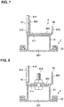
FIG. 7 is a sectional view taken along line VII-VII ofFIG. 3 . -
FIG. 8 is a sectional view taken along line VIII-VIII ofFIG. 3 . -
FIG. 9 is a sectional view taken along line IX-IX ofFIG. 4 . - Hereafter, an embodiment of a seat structure for a vehicle will be described referring to the drawings. The described seat structure for the vehicle is an example of an embodiment of the present invention.
-
FIG. 1 shows a seat 1 for the vehicle. The seat 1 is provided in a cabin of an automotive vehicle, not illustrated. In the example shown inFIG. 1 , this seat 1 is particularly a front seat. The seat 1 is disposed on the left in the cabin. InFIG. 1 , the front-right side on a page is an outward side in a vehicle width direction, and the back-left side on the page is an inward side in the vehicle width direction. The seat structure for the vehicle disclosed here is particularly applicable to a seat which is disposed on the right in the cabin as well. - The seat 1 particularly comprises a
seat cushion 11, aseatback 12, and aheadrest 13. Aframe 14 is particularly installed inside theseat cushion 11. InFIG. 1 , theframe 14 is illustrated so as to be exposed to outside. -
Reference character 2 denotes a seat rail which slides the seat 1 in a vehicle longitudinal direction (hereafter, referred to as a "longitudinal direction" simply). Thisseat rail 2 is particularly arranged below the seat 1. Theseat rail 2 comprises one or more, particularly twoupper rails 21 and one or more, particularly twolower rails 22. The twoupper rails 21 are provided to be spaced apart from each other in the vehicle width direction, which is not illustrated inFIG. 1 . Only one of the twoupper rails 21 is illustrated inFIG. 1 . Each of theupper rails 21 particularly extends in the longitudinal direction. Each of theupper rails 21 is particularly connected to theframe 14, which is not illustrated inFIGS. 1 and2 . - Each of the
lower rails 22 particularly extends in the longitudinal direction. Each of thelower rails 22 is particularly fixed to afloor 23. The twolower rails 22 are provided to be spaced apart from each other in the vehicle width direction. As shown inFIGS. 5-8 , each of thelower rails 22 particularly includes agroove portion 221. Theupper rail 21 and thelower rail 22 are particularly engaged with each other. Theupper rail 21 is particularly provided to be slid along thegroove portion 221 of thelower rail 22 and guided by thelower rail 22. Theupper rail 21 and thelower rail 22 are movable relatively in the longitudinal direction. The seat 1 moves in the longitudinal direction together with the upper rails 21. -
Reference character 3 denotes a seatbelt device, which is configured to restrain an occupant seated in the seat 1. Thisseatbelt device 3 is particularly a three-point type. Theseatbelt device 3 particularly comprises awebbing 31, aretractor 32, afirst anchor 33, asecond anchor 34, abuckle 35, and atongue 36. - The
retractor 32 winds up thewebbing 31. Thefirst anchor 33 particularly fixes a tip of thewebbing 31 to theupper rail 21, which will be specifically described later. Thefirst anchor 33 is particularly positioned on the outward side, in the vehicle width direction, of the seat 1. The tip of thewebbing 31 is particularly fixed to theupper rail 21 at a position located on the outward side, in the vehicle width direction, of the seat 1. Thesecond anchor 34 is particularly fixed to a B pillar, not illustrated. Theanchor 34 particularly changes a direction of thewebbing 31 which is drawn upwardly from theretractor 32 to the downward side. Thebuckle 35 is particularly positioned on the inward side, in the vehicle width direction, of the seat 1. Thebuckle 35 is particularly attached to theupper rail 21, which is not illustrated. Thebuckle 35 and thetongue 36 are configured to be engaged or disengaged. Thetongue 36 is attached to thewebbing 31 between the tip of thewebbing 31 and thesecond anchor 34. - The occupant seated in the seat 1 pulls out the
webbing 31 from theretractor 32 and engages thetongue 36 with thebuckle 35, whereby thewebbing 31 restrains a shoulder part and a waist part of the occupant (not illustrated here). - At least one of, the
first anchor 33 and thebuckle 35, particularly both of thefirst anchor 33 and thebuckle 35 are respectively fixed to the upper rails 21. As the seat 1 moves in the longitudinal direction on theseat rail 2, thefirst anchor 33 and thebuckle 35 move in the longitudinal direction as well. Thefirst anchor 33 and thebuckle 35 are particularly located at appropriate positions which correspond to the seat 1. Thewebbing 31 restrains appropriate respective positions of the shoulder part and the waist part of the occupant. Thus, theseatbelt device 3 can restrain the occupant properly regardless of a body size. -
FIGS. 2-4 show ananchor bracket 4 to fix thefirst anchor 33 to theupper rail 21. Theanchor bracket 4 includes afirst bracket 41 and asecond bracket 42. Thefirst bracket 41 and thesecond bracket 42 are respectively attached to theupper rail 21. - The
first bracket 41 is provided with afirst bottom portion 411 and afirst side portion 412. Thefirst bracket 41 is particularly formed by pressing. - The
first bottom portion 411 particularly extends over a range from a front end portion to a rear end portion of theupper rail 21. As shown inFIGS. 5 and8 , thefirst bottom portion 411 is particularly fixed to theupper rail 21 by using bolts and nuts 415. These bolts andnuts 415 are arranged at one or more, particularly two points of the font end portion and the rear end portion of theupper rail 21 as shown inFIGS. 3 and4 . Theupper rail 21 is configured to have a hat-shaped cross section. Thefirst bottom portion 411 overlaps on an upper surface of theupper rail 21. - The
first side portion 412 is provided to rise upwardly from an inward edge portion, in the vehicle width direction, of thefirst bottom portion 411. Thefirst bracket 41 is particularly configured to have an L-shaped cross section as shown inFIGS. 5 and 6 . Thefirst side portion 412 particularly extends over the range from the front end portion to the rear end portion of theupper rail 21 as well. - The
first bracket 41 particularly includes a rigidity reinforcedpart 413 which is provided at a middle position, in the longitudinal direction, thereof. The rigidity reinforcedpart 413 is particularly provided between thefirst bottom portion 411 and thefirst side portion 412. This rigidity reinforcedpart 413 particularly protrudes in a convex shape in a corner of thefirst bottom portion 411 and thefirst side portion 412. The rigidity reinforcedpart 413 increases the rigidity of thefirst bracket 41. - The
first side portion 412 is particularly provided with ajoint part 414 where a part of thesecond bracket 42 is joined. Thisjoint part 414 is particularly provided at a middle position, in the longitudinal direction, of thefirst side portion 412. Thejoint part 414 is positioned in back of the rigidity reinforcedpart 413. Thejoint part 414 is particularly formed by bending thefirst side portion 412 so as to protrude outwardly in the vehicle width direction as shown inFIGS. 7 and 8 . Thejoint part 414 is configured to have a hat-shaped cross section as shown inFIG. 9 . - The
second bracket 42 is particularly attached to the rear end portion of theupper rail 21. Thesecond bracket 42 particularly has a short length in the longitudinal direction. Thefirst bracket 41 particularly has a longer length in the longitudinal direction than thesecond bracket 42. Since thesecond bracket 42 is attached to the rear end portion of theupper rail 21, thefirst bracket 41 extends forwardly beyond thesecond bracket 42 at the upper surface of theupper rail 21. - The
second bracket 42 is particularly provided with asecond bottom portion 421, asecond side portion 422, and athird side portion 423. Thesecond bracket 42 is particularly formed by pressing. - The
second bottom portion 421 particularly overlaps thefirst bottom portion 411 of thefirst bracket 41 as shown inFIGS. 6 ,7 and 8 . Thesecond bottom portion 421 is particularly joined to thefirst bottom portion 411 by welding, e.g. spot welding, as shown inFIGS. 3 ,4 and6 . Particularly, thesecond bottom portion 421 is also fixed to thefirst bottom portion 411 and theupper rail 21 by using the bolts andnuts 415 as shown inFIGS. 3 ,4 and8 . Welding points 416 and the bolts andnuts 415 are alternately arranged in the longitudinal direction. - The
second side portion 422 is provided to rise upwardly from an inward edge portion, in the vehicle width direction, of thesecond bottom portion 421 as shown inFIGS. 3 ,6 and7 . Thesecond side portion 422 is particularly positioned at a front part of thesecond bracket 42. Thesecond side portion 422 overlaps thejoint part 414 of thefirst side portion 412 in the vehicle width direction as shown inFIGS. 7 and9 . More specifically, thefirst side portion 412 is positioned on the inward side, in the vehicle width direction, of thesecond side portion 422. To the contrary, thesecond side portion 422 is positioned on the outward side, in the vehicle width direction, of thefirst side portion 412. In other words, thefirst side portion 412 is particularly positioned more closely to the seat 1 than thesecond side portion 422. Accordingly, thejoint part 414 is positioned more closely to the seat 1 than thesecond side portion 422. As shown inFIG. 9 , a side face of thesecond side portion 422 and a side face of thejoint part 414 are joined together byarc welding 417 in a state where these two side faces overlap each other. Herein, thesecond side portion 422 and thejoint part 414 may be joined together by using bolts and nuts. - The
third side portion 423 is particularly provided to rise upwardly from an outward edge portion, in the vehicle width direction, of thesecond bottom portion 421 as shown inFIGS. 3 ,6 and7 . Thesecond becket 2 is particularly configured to have a U-shaped cross section which is formed by thesecond bottom portion 421, thesecond side portion 422, and thethird side portion 423. Thethird side portion 423 extends over a range from a front end to a rear end of thesecond bracket 42. Thethird side portion 423 is particularly formed in a substantially triangular shape, when viewed from the outward side in the vehicle width direction. - The
third side portion 423 is particularly provided with ananchor attachment portion 424. Thefirst anchor 33 is attached to theanchor attachment portion 424, which is not illustrated inFIG. 3 . Theanchor attachment portion 424 is provided at an upper end portion of a rear end of thethird side portion 423. - A rigidity reinforced
part 425 is particularly provided at a front end portion of thesecond bracket 42. The rigidity reinforcedpart 425 is formed by bending a front end part of thesecond bottom portion 421. The rigidity reinforcedpart 425 increases the rigidity of thesecond bracket 42. - When the
seatbelt device 3 restrains the occupant, a load F1 which is shown by a white arrow inFIG. 2 is applied to theanchor bracket 4 through thefirst anchor 33. This load F1 can be divided into an upward load F11 and a load F12 which is directed from the outside of the seat 1 toward the center of the seat 1. - Herein, since the
second bracket 42 is fixed to theupper rail 21 via thefirst bracket 41, thefirst bracket 41, thesecond bracket 42, and theupper rail 21 generate a reaction force (resistance) F21 against the upward load F11 (see another white arrow inFIG. 2 ). Herein, thesecond bracket 42 has the short length in the longitudinal direction. Thus, thesecond bracket 42 provides the sufficient resistance against the upward load. - A load F12 in the vehicle width direction which is applied to the
anchor attachment portion 424 is transmitted to thefirst bracket 41 by way of thesecond side portion 422 of thesecond bracket 42 and thejoint part 414. Thefirst bracket 41 and theupper rail 21 generate a reaction force (resistance) F22 against the load F12 (see further another white arrow inFIG. 2 ). Thefirst bracket 41 extends over the range from the front end portion to the rear end portion of theupper rail 21. The load transmitted from thesecond bracket 42 to thefirst bracket 41 is dispersed. Herein, thefirst bracket 41 has a long length in the longitudinal direction, and therefore thefirst bracket 41 can provide the sufficient resistance against the above-described load F12 in the vehicle width direction. Herein, since the longitudinally-longfirst bracket 41 is provided along theupper rail 21, any interference of thefirst bracket 41 with other seat structural members is avoided. - Further, since the rigidity of the
first bracket 41 is increased by the rigidity reinforcedpart 413, thefirst bracket 41 can provide the sufficient resistance against the load F12 in the vehicle width direction. - Moreover, the
joint part 414 of thefirst side portion 412 is positioned more closely to the seat 1 than thesecond side portion 422. In the occupant restraint, the load directed from the outside of the seat 1 toward the center of the seat 1 is applied to thefirst anchor 33 through thewebbing 31 in the vehicle width direction. Since thefirst side portion 412 is positioned more closely to the seat 1 than thesecond side portion 422, thesecond bracket 42 can transmit the load F12 directed from the outside of the seat 1 toward the center of the seat 1 to thefirst bracket 41 effectively. Thefirst bracket 41 can effectively generate the reaction force F22 (i.e., provide the sufficient resistance) against the load F12 directed from the outside of the seat 1 toward the center of the seat 1. - Also, the
joint part 414 of thefirst side portion 412 has the hat-shaped cross section, so that the rigidity of thisjoint part 414 is high. Thefirst bracket 41 can disperse the load in the vehicle width direction which is received from thesecond bracket 42 at an entire part of thefirst bracket 41. Thefirst bracket 41 can generate the sufficient reaction force F22 (i.e., the sufficient resistance) against the load F12 in the vehicle width direction. - Further, since the
second bracket 42 includes the rigidity reinforcedpart 425 at its front end part, the rigidity of thesecond bracket 42 is high. Moreover, the rigidity of thesecond bracket 42 is increased by its U-shape cross section as well. Thesecond bracket 42 can transmit the load F12 in the vehicle width direction to thefirst bracket 41 effectively. - As described above, by configuring the
anchor bracket 4 to comprise thefirst bracket 41 which can generate the reaction force (i.e., provide the resistance) F22 against the load F12 in the vehicle width direction primarily and thesecond bracket 42 which can generate the reaction force (i.e., provide the resistance) F21 against the upward load F11 primarily, theanchor bracket 4 can provide the sufficient resistance against the loads applied to thefirst anchor 33 even if its size is not so large. Consequently, the restraint performance of the occupant by theseatbelt device 3 can be properly improved without any interference of theanchor bracket 4 with the other seat structural members. - Also, as shown in
FIG. 4 , a load application (input) position of theanchor attachment portion 424 is spaced apart, in the longitudinal direction, from the welding points 416 and the bolts andnuts 415 for fixing thesecond bracket 42 by a distance L1. When the load is applied (inputted) to theanchor attachment portion 424, a moment M around an axis extending in the vehicle width direction acts on thefirst bracket 41 and thesecond bracket 42 as shown by a solid arrow inFIG. 4 . This moment M is a counterclockwise moment in the illustrated example. Thefirst bracket 41 extends forwardly beyond the second bracket 42 (see L2 shown inFIG. 4 ). The longitudinally-longfirst bracket 41 can resist the moment M. Thefirst bracket 41 and thesecond bracket 42 can properly withstand the moment M acting on theanchor bracket 4. - Further, the
joint part 414 of thefirst bracket 41 and thesecond side portion 422 of thesecond bracket 42 are joined together by arc welding so as to overlap each other in the vehicle width direction. According to this structure, the load applied to thefirst bracket 41 from thesecond bracket 42 is a shearing load. Thefirst bracket 41 and thesecond bracket 42 which are joined together at their side faces show enhanced resistance against the shearing load. Accordingly, theanchor bracket 4 can provide the high load-resistance performance. - Moreover, since the
first bracket 41 and thesecond bracket 42 are different (separated) members from each other, the plate thickness of thefirst bracket 41 and the plate thickness of thesecond bracket 42 can be differentiated. The load applied to thefirst anchor 33 is directly inputted to thesecond bracket 42, so that thesecond bracket 42 can resist the larger load by increasing the plate thickness of thesecond bracket 42. Meanwhile, it is unnecessary that the plate thickness of thefirst bracket 41 is made to be equal to that of the second bracket. The plate thickness of thefirst bracket 41 may be made thinner than that of thesecond bracket 42. The weight of theanchor bracket 4 is reduced by making the plate thickness of thefirst bracket 41 thinner. Theanchor bracket 4 comprising thefirst bracket 41 and thesecond bracket 42 improves the load resistance performance without the weight increase. - As shown in
FIGS. 6 - 8 , thesecond bracket 42 is particularly provided to protrude outwardly, in the vehicle width direction, beyond theupper rail 21. In the figures, thesecond bracket 42 is illustrated so as to protrude to the right on each page. Since thesecond bracket 42 protrudes beyond theupper rail 21, this protrusion portion is configured in a cantilever state. In general, when the load is applied to a bracket configured in the cantilever state, it is likely that this bracket is deformed. Meanwhile, theanchor bracket 4 comprising thefirst bracket 41 and thesecond bracket 42 can receive the load by corporation of thefirst bracket 41 and thesecond bracket 42 even when the load from thefirst anchor 33 is applied to thesecond bracket 42 configured in the cantilever state. - Herein, the arrangement position of the
seat rail 2 is decided based on a vehicle-body structure, and the size of theanchor bracket 4 is decided by a magnitude of the load inputted and a shape and/or structure of the seat 1. Accordingly, there is a case where thesecond bracket 42 protrudes outwardly, in the vehicle width direction, beyond the upper rail 21 (i.e., protrudes to the outside of the seat 1). In this case, theanchor bracket 4 of this embodiment can receive the load properly. That is, theanchor bracket 4 of the present structure increases the flexibility of the arrangement position of theseat rail 2 and the size of theanchor bracket 4. - Herein, the anchor bracket to fix the
buckle 35 to theupper rail 21 may be configured to have the same structure as theanchor bracket 4, which is not illustrated. That is, the anchor bracket described here may be the bracket to fix the buckle to the rail. - Additionally, the seat structure for the vehicle described here is not limited to application to the front seat. The seat structure for the vehicle described here is widely applicable to any seat comprising the seat rail to slide the seat in the longitudinal direction.
Claims (15)
- A seat structure for a vehicle, comprising:a seat (1);a seat rail (2) to be fixed to a vehicle body, the seat rail (2) comprising a lower rail (22) including a groove portion (221) to be disposed to extend in a vehicle longitudinal direction and an upper rail (21) provided to be slid in the groove portion (221) of the lower rail (22) and guided by the lower rail (22); andan anchor bracket (4) configured to fix an anchor (33) or a buckle (35) of a seatbelt device (3) to the upper rail (21) of the seat rail (2),wherein said anchor bracket (4) includes a first bracket (41) provided with a first bottom portion (411) fixed to said upper rail (21) and a first side portion (412) rising upwardly from said first bottom portion (411) and a second bracket (42) provided with a second bottom portion (421) fixed to said upper rail (21), a second side portion (422) rising upwardly from said second bottom portion (421), and an anchor attachment portion (424) where said anchor (33) is attached,said first side portion (412) of the first bracket (41) and said second side portion (422) of the second bracket (42) are joined together so as to overlap each other in a vehicle width direction, andsaid first bracket (41) is provided to extend forwardly beyond said second bracket (42) at an upper surface of said upper rail (21) of the seat rail (2).
- The seat structure for the vehicle of claim 1, wherein said first bracket (41) is longer than said second bracket (42) in the vehicle longitudinal direction.
- The seat structure for the vehicle of claims 1 or 2, wherein said first side portion (412) of the first bracket (41) is positioned more closely to said seat (1) than said second side portion (422) of the second bracket (42).
- The seat structure for the vehicle of any of the preceding claims, wherein a joint part (414) of said first side portion (412) of the first bracket (41) to said second side portion (422) of the second bracket (42) is configured to have a hat-shaped cross section.
- The seat structure for the vehicle of any of the preceding claims, wherein said second bracket (42) includes a rigidity reinforced part (425) which is provided at a front end part of said second bottom portion (421).
- The seat structure for the vehicle of any of the preceding claims, wherein said second bracket (42) is provided with a third side portion (423) which is provided to rise upwardly from said second bottom portion (421) and faces said second side portion (422), and said anchor attachment portion (424) is provided at said third side portion.
- The seat structure for the vehicle of any of the preceding claims, wherein said first bracket (41) is provided to extend over a range from a front end portion and a rear end portion of said upper rail (21) of the seat rail (2).
- The seat structure for the vehicle of any of the preceding claims, wherein said second bottom portion (421) of the second bracket (42) is fixed to said upper rail (21) of the seat rail (2) in a state where the second bottom portion (421) overlaps on said first bottom portion (411) of the first bracket (41).
- The seat structure for the vehicle of any of the preceding claims, wherein said second bracket (42) fixed to the upper rail (21) is provided to protrude outwardly, in the vehicle width direction, beyond the upper rail (21).
- The seat structure for the vehicle of any of the preceding claims, wherein the seat rail (2) is to be provided below the seat (1).
- The seat structure for the vehicle of any of the preceding claims, wherein the second side portion (422) of the second bracket (42) is to be disposed between a center of the seat (1) and the anchor attachment portion (424) of the second bracket (42) in the vehicle width direction.
- The seat structure for the vehicle of claim 11, wherein the first side portion (412) of the first bracket (41) is to be disposed between the center of the seat (1) and the second side portion (422) of the second bracket (42).
- The seat structure for the vehicle of any of the preceding claims, wherein the first bottom portion (411) of the first bracket (41) and the second bottom portion (421) of the second bracket (42) are joined by welding.
- The seat structure for the vehicle of any of the preceding claims, wherein the first side portion (412) of the first bracket (41) and the second side portion (422) of the second bracket (42) are joined by welding.
- A vehicle comprising:a vehicle body;a seatbelt device (3) with an anchor (33) and/or a buckle (35); andthe seat structure for the vehicle of any one of the preceding claims.
Applications Claiming Priority (2)
| Application Number | Priority Date | Filing Date | Title |
|---|---|---|---|
| JP2018220861 | 2018-11-27 | ||
| JP2019144878A JP7318405B2 (en) | 2018-11-27 | 2019-08-06 | vehicle seat structure |
Publications (2)
| Publication Number | Publication Date |
|---|---|
| EP3674135A1 true EP3674135A1 (en) | 2020-07-01 |
| EP3674135B1 EP3674135B1 (en) | 2021-06-09 |
Family
ID=68653312
Family Applications (1)
| Application Number | Title | Priority Date | Filing Date |
|---|---|---|---|
| EP19210512.0A Active EP3674135B1 (en) | 2018-11-27 | 2019-11-21 | Seat structure for vehicle, and vehicle |
Country Status (3)
| Country | Link |
|---|---|
| US (1) | US11072308B2 (en) |
| EP (1) | EP3674135B1 (en) |
| CN (1) | CN111216604B (en) |
Cited By (1)
| Publication number | Priority date | Publication date | Assignee | Title |
|---|---|---|---|---|
| US20220388431A1 (en) * | 2019-07-17 | 2022-12-08 | Ts Tech Co., Ltd. | Conveyance seat |
Families Citing this family (2)
| Publication number | Priority date | Publication date | Assignee | Title |
|---|---|---|---|---|
| US20220295739A1 (en) * | 2021-03-19 | 2022-09-22 | Sure Loc Pet Carriers LLC | Pet carrier |
| KR20250022436A (en) * | 2023-08-08 | 2025-02-17 | 현대자동차주식회사 | Seat belt device and method for mounting the seat belt device |
Citations (1)
| Publication number | Priority date | Publication date | Assignee | Title |
|---|---|---|---|---|
| US20080048086A1 (en) | 2006-08-25 | 2008-02-28 | Aisin Seiki Kabushiki Kaisha | Seat slide apparatus for vehicle |
Family Cites Families (20)
| Publication number | Priority date | Publication date | Assignee | Title |
|---|---|---|---|---|
| JPH0439084Y2 (en) * | 1985-12-09 | 1992-09-11 | ||
| JP3649425B2 (en) * | 1997-09-18 | 2005-05-18 | 関東自動車工業株式会社 | Car seat equipment |
| JP2000038165A (en) * | 1998-07-21 | 2000-02-08 | Daihatsu Motor Co Ltd | Body lower side part reinforcing structure for automobile |
| JP3560846B2 (en) * | 1999-05-11 | 2004-09-02 | 富士機工株式会社 | Seat slide device |
| WO2003093052A1 (en) * | 2002-04-30 | 2003-11-13 | Brose Fahrzeugteile Gmbh & Co. Kg; Coburg | Longitudinal guide rail for a motor vehicle seat |
| FR2886241B1 (en) * | 2005-05-27 | 2007-08-03 | Euramax Ind Sa Sa | SLIDING ASSEMBLY FOR A VEHICLE |
| JP2007050784A (en) * | 2005-08-18 | 2007-03-01 | Mazda Motor Corp | Mounting structure for vehicle seat |
| JP5275622B2 (en) * | 2007-12-26 | 2013-08-28 | トヨタ紡織株式会社 | Vehicle seat |
| JP5434102B2 (en) * | 2009-01-29 | 2014-03-05 | アイシン精機株式会社 | Vehicle seat slide device |
| JP5097790B2 (en) * | 2010-03-24 | 2012-12-12 | トヨタ紡織株式会社 | Vehicle seat |
| PL2644443T3 (en) * | 2010-11-22 | 2015-12-31 | Johnson Controls Tech Co | Vehicle seat |
| FR2988665B1 (en) * | 2012-04-02 | 2014-04-25 | Peugeot Citroen Automobiles Sa | SEAT STRUCTURE OF A MOTOR VEHICLE SEAT COMPRISING A BELT BUCKLE OF A SAFETY BELT. |
| JP5921307B2 (en) * | 2012-04-18 | 2016-05-24 | 日本発條株式会社 | Vehicle seat |
| WO2014045423A1 (en) * | 2012-09-21 | 2014-03-27 | テイ・エス テック株式会社 | Vehicle seat |
| JP6442349B2 (en) * | 2014-04-25 | 2018-12-19 | トヨタ紡織株式会社 | Vehicle seat |
| TWM498687U (en) * | 2014-12-17 | 2015-04-11 | Hsin Chong Machinery Works Co | Sliding mechanism for vehicular seat |
| JP6169134B2 (en) * | 2015-07-01 | 2017-07-26 | 本田技研工業株式会社 | Vehicle seat rail |
| CN205311377U (en) * | 2015-12-08 | 2016-06-15 | 重庆宏立至信汽车部件制造有限公司 | Seat four -bar linkage fore -stock subassembly |
| CN109789898B (en) * | 2016-09-21 | 2021-10-12 | 本田技研工业株式会社 | Seat mounting structure |
| JP6922756B2 (en) * | 2018-01-23 | 2021-08-18 | トヨタ自動車株式会社 | Vehicle seat belt device |
-
2019
- 2019-11-21 US US16/690,532 patent/US11072308B2/en active Active
- 2019-11-21 EP EP19210512.0A patent/EP3674135B1/en active Active
- 2019-11-22 CN CN201911153394.3A patent/CN111216604B/en active Active
Patent Citations (2)
| Publication number | Priority date | Publication date | Assignee | Title |
|---|---|---|---|---|
| US20080048086A1 (en) | 2006-08-25 | 2008-02-28 | Aisin Seiki Kabushiki Kaisha | Seat slide apparatus for vehicle |
| JP2008049893A (en) | 2006-08-25 | 2008-03-06 | Aisin Seiki Co Ltd | Vehicle seat slide device |
Cited By (3)
| Publication number | Priority date | Publication date | Assignee | Title |
|---|---|---|---|---|
| US20220388431A1 (en) * | 2019-07-17 | 2022-12-08 | Ts Tech Co., Ltd. | Conveyance seat |
| US11794614B2 (en) * | 2019-07-17 | 2023-10-24 | Ts Tech Co., Ltd. | Conveyance seat |
| US12179641B2 (en) | 2019-07-17 | 2024-12-31 | Ts Tech Co., Ltd. | Conveyance seat |
Also Published As
| Publication number | Publication date |
|---|---|
| US20200164832A1 (en) | 2020-05-28 |
| CN111216604B (en) | 2022-05-03 |
| US11072308B2 (en) | 2021-07-27 |
| CN111216604A (en) | 2020-06-02 |
| EP3674135B1 (en) | 2021-06-09 |
Similar Documents
| Publication | Publication Date | Title |
|---|---|---|
| JP5690093B2 (en) | Vehicle seat structure | |
| EP3674135B1 (en) | Seat structure for vehicle, and vehicle | |
| JP2010285083A (en) | Vehicle seat | |
| EP2644443B1 (en) | Vehicle seat | |
| US20130193737A1 (en) | Seat cushion frame for vehicle | |
| US11472323B2 (en) | Frame structure for a vehicle seat backrest | |
| US11440500B2 (en) | Vehicle occupant restraint structure | |
| US20150203000A1 (en) | Vehicle seat | |
| CN109552124B (en) | vehicle seat | |
| EP4071005A1 (en) | Seat belt assembly | |
| JP5835657B2 (en) | Rear structure of the vehicle | |
| EP3730355B1 (en) | Vehicular passenger restraint device | |
| JP6169134B2 (en) | Vehicle seat rail | |
| JP4222235B2 (en) | Sheet | |
| KR100337830B1 (en) | Baggage intrusion prevention structure of trunk room | |
| JP7318405B2 (en) | vehicle seat structure | |
| JP5470822B2 (en) | Crew protection device | |
| KR102935746B1 (en) | Seat frame assembly for kids safety vehicle | |
| JP4395875B2 (en) | Seat belt anchor structure | |
| EP4556304A1 (en) | A load absorption device to be used with a vehicle seat, a vehicle occupant protection system using such device and a method of operating a system | |
| JP7764982B2 (en) | Bracket holding structure | |
| JP3911818B2 (en) | Vehicle seat belt device | |
| JP5510284B2 (en) | Buckle structure for seat belt | |
| US20250206123A1 (en) | Vehicle lower part structure | |
| JP2019182017A (en) | Seatbelt device for vehicle |
Legal Events
| Date | Code | Title | Description |
|---|---|---|---|
| PUAI | Public reference made under article 153(3) epc to a published international application that has entered the european phase |
Free format text: ORIGINAL CODE: 0009012 |
|
| STAA | Information on the status of an ep patent application or granted ep patent |
Free format text: STATUS: THE APPLICATION HAS BEEN PUBLISHED |
|
| AK | Designated contracting states |
Kind code of ref document: A1 Designated state(s): AL AT BE BG CH CY CZ DE DK EE ES FI FR GB GR HR HU IE IS IT LI LT LU LV MC MK MT NL NO PL PT RO RS SE SI SK SM TR |
|
| AX | Request for extension of the european patent |
Extension state: BA ME |
|
| STAA | Information on the status of an ep patent application or granted ep patent |
Free format text: STATUS: REQUEST FOR EXAMINATION WAS MADE |
|
| 17P | Request for examination filed |
Effective date: 20201029 |
|
| RBV | Designated contracting states (corrected) |
Designated state(s): AL AT BE BG CH CY CZ DE DK EE ES FI FR GB GR HR HU IE IS IT LI LT LU LV MC MK MT NL NO PL PT RO RS SE SI SK SM TR |
|
| GRAP | Despatch of communication of intention to grant a patent |
Free format text: ORIGINAL CODE: EPIDOSNIGR1 |
|
| STAA | Information on the status of an ep patent application or granted ep patent |
Free format text: STATUS: GRANT OF PATENT IS INTENDED |
|
| INTG | Intention to grant announced |
Effective date: 20210129 |
|
| GRAS | Grant fee paid |
Free format text: ORIGINAL CODE: EPIDOSNIGR3 |
|
| GRAA | (expected) grant |
Free format text: ORIGINAL CODE: 0009210 |
|
| STAA | Information on the status of an ep patent application or granted ep patent |
Free format text: STATUS: THE PATENT HAS BEEN GRANTED |
|
| AK | Designated contracting states |
Kind code of ref document: B1 Designated state(s): AL AT BE BG CH CY CZ DE DK EE ES FI FR GB GR HR HU IE IS IT LI LT LU LV MC MK MT NL NO PL PT RO RS SE SI SK SM TR |
|
| REG | Reference to a national code |
Ref country code: GB Ref legal event code: FG4D |
|
| REG | Reference to a national code |
Ref country code: CH Ref legal event code: EP Ref country code: AT Ref legal event code: REF Ref document number: 1400199 Country of ref document: AT Kind code of ref document: T Effective date: 20210615 |
|
| REG | Reference to a national code |
Ref country code: DE Ref legal event code: R096 Ref document number: 602019005249 Country of ref document: DE |
|
| REG | Reference to a national code |
Ref country code: IE Ref legal event code: FG4D |
|
| REG | Reference to a national code |
Ref country code: LT Ref legal event code: MG9D |
|
| PG25 | Lapsed in a contracting state [announced via postgrant information from national office to epo] |
Ref country code: FI Free format text: LAPSE BECAUSE OF FAILURE TO SUBMIT A TRANSLATION OF THE DESCRIPTION OR TO PAY THE FEE WITHIN THE PRESCRIBED TIME-LIMIT Effective date: 20210609 Ref country code: LT Free format text: LAPSE BECAUSE OF FAILURE TO SUBMIT A TRANSLATION OF THE DESCRIPTION OR TO PAY THE FEE WITHIN THE PRESCRIBED TIME-LIMIT Effective date: 20210609 Ref country code: HR Free format text: LAPSE BECAUSE OF FAILURE TO SUBMIT A TRANSLATION OF THE DESCRIPTION OR TO PAY THE FEE WITHIN THE PRESCRIBED TIME-LIMIT Effective date: 20210609 Ref country code: BG Free format text: LAPSE BECAUSE OF FAILURE TO SUBMIT A TRANSLATION OF THE DESCRIPTION OR TO PAY THE FEE WITHIN THE PRESCRIBED TIME-LIMIT Effective date: 20210909 |
|
| REG | Reference to a national code |
Ref country code: AT Ref legal event code: MK05 Ref document number: 1400199 Country of ref document: AT Kind code of ref document: T Effective date: 20210609 |
|
| REG | Reference to a national code |
Ref country code: NL Ref legal event code: MP Effective date: 20210609 |
|
| PG25 | Lapsed in a contracting state [announced via postgrant information from national office to epo] |
Ref country code: GR Free format text: LAPSE BECAUSE OF FAILURE TO SUBMIT A TRANSLATION OF THE DESCRIPTION OR TO PAY THE FEE WITHIN THE PRESCRIBED TIME-LIMIT Effective date: 20210910 Ref country code: RS Free format text: LAPSE BECAUSE OF FAILURE TO SUBMIT A TRANSLATION OF THE DESCRIPTION OR TO PAY THE FEE WITHIN THE PRESCRIBED TIME-LIMIT Effective date: 20210609 Ref country code: SE Free format text: LAPSE BECAUSE OF FAILURE TO SUBMIT A TRANSLATION OF THE DESCRIPTION OR TO PAY THE FEE WITHIN THE PRESCRIBED TIME-LIMIT Effective date: 20210609 Ref country code: NO Free format text: LAPSE BECAUSE OF FAILURE TO SUBMIT A TRANSLATION OF THE DESCRIPTION OR TO PAY THE FEE WITHIN THE PRESCRIBED TIME-LIMIT Effective date: 20210909 Ref country code: LV Free format text: LAPSE BECAUSE OF FAILURE TO SUBMIT A TRANSLATION OF THE DESCRIPTION OR TO PAY THE FEE WITHIN THE PRESCRIBED TIME-LIMIT Effective date: 20210609 |
|
| PG25 | Lapsed in a contracting state [announced via postgrant information from national office to epo] |
Ref country code: SK Free format text: LAPSE BECAUSE OF FAILURE TO SUBMIT A TRANSLATION OF THE DESCRIPTION OR TO PAY THE FEE WITHIN THE PRESCRIBED TIME-LIMIT Effective date: 20210609 Ref country code: EE Free format text: LAPSE BECAUSE OF FAILURE TO SUBMIT A TRANSLATION OF THE DESCRIPTION OR TO PAY THE FEE WITHIN THE PRESCRIBED TIME-LIMIT Effective date: 20210609 Ref country code: ES Free format text: LAPSE BECAUSE OF FAILURE TO SUBMIT A TRANSLATION OF THE DESCRIPTION OR TO PAY THE FEE WITHIN THE PRESCRIBED TIME-LIMIT Effective date: 20210609 Ref country code: AT Free format text: LAPSE BECAUSE OF FAILURE TO SUBMIT A TRANSLATION OF THE DESCRIPTION OR TO PAY THE FEE WITHIN THE PRESCRIBED TIME-LIMIT Effective date: 20210609 Ref country code: CZ Free format text: LAPSE BECAUSE OF FAILURE TO SUBMIT A TRANSLATION OF THE DESCRIPTION OR TO PAY THE FEE WITHIN THE PRESCRIBED TIME-LIMIT Effective date: 20210609 Ref country code: NL Free format text: LAPSE BECAUSE OF FAILURE TO SUBMIT A TRANSLATION OF THE DESCRIPTION OR TO PAY THE FEE WITHIN THE PRESCRIBED TIME-LIMIT Effective date: 20210609 Ref country code: PT Free format text: LAPSE BECAUSE OF FAILURE TO SUBMIT A TRANSLATION OF THE DESCRIPTION OR TO PAY THE FEE WITHIN THE PRESCRIBED TIME-LIMIT Effective date: 20211011 Ref country code: RO Free format text: LAPSE BECAUSE OF FAILURE TO SUBMIT A TRANSLATION OF THE DESCRIPTION OR TO PAY THE FEE WITHIN THE PRESCRIBED TIME-LIMIT Effective date: 20210609 Ref country code: SM Free format text: LAPSE BECAUSE OF FAILURE TO SUBMIT A TRANSLATION OF THE DESCRIPTION OR TO PAY THE FEE WITHIN THE PRESCRIBED TIME-LIMIT Effective date: 20210609 |
|
| PGFP | Annual fee paid to national office [announced via postgrant information from national office to epo] |
Ref country code: DE Payment date: 20211012 Year of fee payment: 3 |
|
| PG25 | Lapsed in a contracting state [announced via postgrant information from national office to epo] |
Ref country code: PL Free format text: LAPSE BECAUSE OF FAILURE TO SUBMIT A TRANSLATION OF THE DESCRIPTION OR TO PAY THE FEE WITHIN THE PRESCRIBED TIME-LIMIT Effective date: 20210609 |
|
| REG | Reference to a national code |
Ref country code: DE Ref legal event code: R097 Ref document number: 602019005249 Country of ref document: DE |
|
| PLBE | No opposition filed within time limit |
Free format text: ORIGINAL CODE: 0009261 |
|
| STAA | Information on the status of an ep patent application or granted ep patent |
Free format text: STATUS: NO OPPOSITION FILED WITHIN TIME LIMIT |
|
| PG25 | Lapsed in a contracting state [announced via postgrant information from national office to epo] |
Ref country code: DK Free format text: LAPSE BECAUSE OF FAILURE TO SUBMIT A TRANSLATION OF THE DESCRIPTION OR TO PAY THE FEE WITHIN THE PRESCRIBED TIME-LIMIT Effective date: 20210609 |
|
| 26N | No opposition filed |
Effective date: 20220310 |
|
| PG25 | Lapsed in a contracting state [announced via postgrant information from national office to epo] |
Ref country code: AL Free format text: LAPSE BECAUSE OF FAILURE TO SUBMIT A TRANSLATION OF THE DESCRIPTION OR TO PAY THE FEE WITHIN THE PRESCRIBED TIME-LIMIT Effective date: 20210609 |
|
| PG25 | Lapsed in a contracting state [announced via postgrant information from national office to epo] |
Ref country code: MC Free format text: LAPSE BECAUSE OF FAILURE TO SUBMIT A TRANSLATION OF THE DESCRIPTION OR TO PAY THE FEE WITHIN THE PRESCRIBED TIME-LIMIT Effective date: 20210609 |
|
| PG25 | Lapsed in a contracting state [announced via postgrant information from national office to epo] |
Ref country code: LU Free format text: LAPSE BECAUSE OF NON-PAYMENT OF DUE FEES Effective date: 20211121 Ref country code: IT Free format text: LAPSE BECAUSE OF FAILURE TO SUBMIT A TRANSLATION OF THE DESCRIPTION OR TO PAY THE FEE WITHIN THE PRESCRIBED TIME-LIMIT Effective date: 20210609 Ref country code: BE Free format text: LAPSE BECAUSE OF NON-PAYMENT OF DUE FEES Effective date: 20211130 |
|
| REG | Reference to a national code |
Ref country code: BE Ref legal event code: MM Effective date: 20211130 |
|
| PG25 | Lapsed in a contracting state [announced via postgrant information from national office to epo] |
Ref country code: IE Free format text: LAPSE BECAUSE OF NON-PAYMENT OF DUE FEES Effective date: 20211121 |
|
| PG25 | Lapsed in a contracting state [announced via postgrant information from national office to epo] |
Ref country code: FR Free format text: LAPSE BECAUSE OF NON-PAYMENT OF DUE FEES Effective date: 20211130 |
|
| REG | Reference to a national code |
Ref country code: DE Ref legal event code: R119 Ref document number: 602019005249 Country of ref document: DE |
|
| PG25 | Lapsed in a contracting state [announced via postgrant information from national office to epo] |
Ref country code: CY Free format text: LAPSE BECAUSE OF FAILURE TO SUBMIT A TRANSLATION OF THE DESCRIPTION OR TO PAY THE FEE WITHIN THE PRESCRIBED TIME-LIMIT Effective date: 20210609 |
|
| REG | Reference to a national code |
Ref country code: CH Ref legal event code: PL |
|
| PG25 | Lapsed in a contracting state [announced via postgrant information from national office to epo] |
Ref country code: LI Free format text: LAPSE BECAUSE OF NON-PAYMENT OF DUE FEES Effective date: 20221130 Ref country code: HU Free format text: LAPSE BECAUSE OF FAILURE TO SUBMIT A TRANSLATION OF THE DESCRIPTION OR TO PAY THE FEE WITHIN THE PRESCRIBED TIME-LIMIT; INVALID AB INITIO Effective date: 20191121 Ref country code: CH Free format text: LAPSE BECAUSE OF NON-PAYMENT OF DUE FEES Effective date: 20221130 |
|
| PG25 | Lapsed in a contracting state [announced via postgrant information from national office to epo] |
Ref country code: DE Free format text: LAPSE BECAUSE OF NON-PAYMENT OF DUE FEES Effective date: 20230601 |
|
| PG25 | Lapsed in a contracting state [announced via postgrant information from national office to epo] |
Ref country code: MK Free format text: LAPSE BECAUSE OF FAILURE TO SUBMIT A TRANSLATION OF THE DESCRIPTION OR TO PAY THE FEE WITHIN THE PRESCRIBED TIME-LIMIT Effective date: 20210609 |
|
| PG25 | Lapsed in a contracting state [announced via postgrant information from national office to epo] |
Ref country code: TR Free format text: LAPSE BECAUSE OF FAILURE TO SUBMIT A TRANSLATION OF THE DESCRIPTION OR TO PAY THE FEE WITHIN THE PRESCRIBED TIME-LIMIT Effective date: 20210609 |
|
| GBPC | Gb: european patent ceased through non-payment of renewal fee |
Effective date: 20231121 |
|
| PG25 | Lapsed in a contracting state [announced via postgrant information from national office to epo] |
Ref country code: MT Free format text: LAPSE BECAUSE OF FAILURE TO SUBMIT A TRANSLATION OF THE DESCRIPTION OR TO PAY THE FEE WITHIN THE PRESCRIBED TIME-LIMIT Effective date: 20210609 |
|
| PG25 | Lapsed in a contracting state [announced via postgrant information from national office to epo] |
Ref country code: GB Free format text: LAPSE BECAUSE OF NON-PAYMENT OF DUE FEES Effective date: 20231121 |
|
| PG25 | Lapsed in a contracting state [announced via postgrant information from national office to epo] |
Ref country code: GB Free format text: LAPSE BECAUSE OF NON-PAYMENT OF DUE FEES Effective date: 20231121 |