EP3674069A1 - Resin impregnation measurement device - Google Patents
Resin impregnation measurement device Download PDFInfo
- Publication number
- EP3674069A1 EP3674069A1 EP19209434.0A EP19209434A EP3674069A1 EP 3674069 A1 EP3674069 A1 EP 3674069A1 EP 19209434 A EP19209434 A EP 19209434A EP 3674069 A1 EP3674069 A1 EP 3674069A1
- Authority
- EP
- European Patent Office
- Prior art keywords
- resin
- base material
- fiber base
- stringer
- skin
- Prior art date
- Legal status (The legal status is an assumption and is not a legal conclusion. Google has not performed a legal analysis and makes no representation as to the accuracy of the status listed.)
- Granted
Links
Images

Classifications
-
- B—PERFORMING OPERATIONS; TRANSPORTING
- B29—WORKING OF PLASTICS; WORKING OF SUBSTANCES IN A PLASTIC STATE IN GENERAL
- B29C—SHAPING OR JOINING OF PLASTICS; SHAPING OF MATERIAL IN A PLASTIC STATE, NOT OTHERWISE PROVIDED FOR; AFTER-TREATMENT OF THE SHAPED PRODUCTS, e.g. REPAIRING
- B29C43/00—Compression moulding, i.e. applying external pressure to flow the moulding material; Apparatus therefor
- B29C43/32—Component parts, details or accessories; Auxiliary operations
- B29C43/58—Measuring, controlling or regulating
-
- B—PERFORMING OPERATIONS; TRANSPORTING
- B29—WORKING OF PLASTICS; WORKING OF SUBSTANCES IN A PLASTIC STATE IN GENERAL
- B29C—SHAPING OR JOINING OF PLASTICS; SHAPING OF MATERIAL IN A PLASTIC STATE, NOT OTHERWISE PROVIDED FOR; AFTER-TREATMENT OF THE SHAPED PRODUCTS, e.g. REPAIRING
- B29C70/00—Shaping composites, i.e. plastics material comprising reinforcements, fillers or preformed parts, e.g. inserts
- B29C70/04—Shaping composites, i.e. plastics material comprising reinforcements, fillers or preformed parts, e.g. inserts comprising reinforcements only, e.g. self-reinforcing plastics
- B29C70/28—Shaping operations therefor
- B29C70/54—Component parts, details or accessories; Auxiliary operations, e.g. feeding or storage of prepregs or SMC after impregnation or during ageing
- B29C70/546—Measures for feeding or distributing the matrix material in the reinforcing structure
-
- B—PERFORMING OPERATIONS; TRANSPORTING
- B29—WORKING OF PLASTICS; WORKING OF SUBSTANCES IN A PLASTIC STATE IN GENERAL
- B29C—SHAPING OR JOINING OF PLASTICS; SHAPING OF MATERIAL IN A PLASTIC STATE, NOT OTHERWISE PROVIDED FOR; AFTER-TREATMENT OF THE SHAPED PRODUCTS, e.g. REPAIRING
- B29C43/00—Compression moulding, i.e. applying external pressure to flow the moulding material; Apparatus therefor
- B29C43/32—Component parts, details or accessories; Auxiliary operations
- B29C43/36—Moulds for making articles of definite length, i.e. discrete articles
- B29C43/3642—Bags, bleeder sheets or cauls for isostatic pressing
-
- B—PERFORMING OPERATIONS; TRANSPORTING
- B29—WORKING OF PLASTICS; WORKING OF SUBSTANCES IN A PLASTIC STATE IN GENERAL
- B29C—SHAPING OR JOINING OF PLASTICS; SHAPING OF MATERIAL IN A PLASTIC STATE, NOT OTHERWISE PROVIDED FOR; AFTER-TREATMENT OF THE SHAPED PRODUCTS, e.g. REPAIRING
- B29C70/00—Shaping composites, i.e. plastics material comprising reinforcements, fillers or preformed parts, e.g. inserts
- B29C70/04—Shaping composites, i.e. plastics material comprising reinforcements, fillers or preformed parts, e.g. inserts comprising reinforcements only, e.g. self-reinforcing plastics
- B29C70/28—Shaping operations therefor
- B29C70/40—Shaping or impregnating by compression not applied
- B29C70/42—Shaping or impregnating by compression not applied for producing articles of definite length, i.e. discrete articles
- B29C70/44—Shaping or impregnating by compression not applied for producing articles of definite length, i.e. discrete articles using isostatic pressure, e.g. pressure difference-moulding, vacuum bag-moulding, autoclave-moulding or expanding rubber-moulding
- B29C70/443—Shaping or impregnating by compression not applied for producing articles of definite length, i.e. discrete articles using isostatic pressure, e.g. pressure difference-moulding, vacuum bag-moulding, autoclave-moulding or expanding rubber-moulding and impregnating by vacuum or injection
-
- B—PERFORMING OPERATIONS; TRANSPORTING
- B29—WORKING OF PLASTICS; WORKING OF SUBSTANCES IN A PLASTIC STATE IN GENERAL
- B29C—SHAPING OR JOINING OF PLASTICS; SHAPING OF MATERIAL IN A PLASTIC STATE, NOT OTHERWISE PROVIDED FOR; AFTER-TREATMENT OF THE SHAPED PRODUCTS, e.g. REPAIRING
- B29C70/00—Shaping composites, i.e. plastics material comprising reinforcements, fillers or preformed parts, e.g. inserts
- B29C70/04—Shaping composites, i.e. plastics material comprising reinforcements, fillers or preformed parts, e.g. inserts comprising reinforcements only, e.g. self-reinforcing plastics
- B29C70/28—Shaping operations therefor
- B29C70/40—Shaping or impregnating by compression not applied
- B29C70/42—Shaping or impregnating by compression not applied for producing articles of definite length, i.e. discrete articles
- B29C70/46—Shaping or impregnating by compression not applied for producing articles of definite length, i.e. discrete articles using matched moulds, e.g. for deforming sheet moulding compounds [SMC] or prepregs
- B29C70/48—Shaping or impregnating by compression not applied for producing articles of definite length, i.e. discrete articles using matched moulds, e.g. for deforming sheet moulding compounds [SMC] or prepregs and impregnating the reinforcements in the closed mould, e.g. resin transfer moulding [RTM], e.g. by vacuum
-
- B—PERFORMING OPERATIONS; TRANSPORTING
- B29—WORKING OF PLASTICS; WORKING OF SUBSTANCES IN A PLASTIC STATE IN GENERAL
- B29D—PRODUCING PARTICULAR ARTICLES FROM PLASTICS OR FROM SUBSTANCES IN A PLASTIC STATE
- B29D99/00—Subject matter not provided for in other groups of this subclass
- B29D99/001—Producing wall or panel-like structures, e.g. for hulls, fuselages, or buildings
- B29D99/0014—Producing wall or panel-like structures, e.g. for hulls, fuselages, or buildings provided with ridges or ribs, e.g. joined ribs
-
- G—PHYSICS
- G01—MEASURING; TESTING
- G01F—MEASURING VOLUME, VOLUME FLOW, MASS FLOW OR LIQUID LEVEL; METERING BY VOLUME
- G01F23/00—Indicating or measuring liquid level or level of fluent solid material, e.g. indicating in terms of volume or indicating by means of an alarm
- G01F23/22—Indicating or measuring liquid level or level of fluent solid material, e.g. indicating in terms of volume or indicating by means of an alarm by measuring physical variables, other than linear dimensions, pressure or weight, dependent on the level to be measured, e.g. by difference of heat transfer of steam or water
- G01F23/26—Indicating or measuring liquid level or level of fluent solid material, e.g. indicating in terms of volume or indicating by means of an alarm by measuring physical variables, other than linear dimensions, pressure or weight, dependent on the level to be measured, e.g. by difference of heat transfer of steam or water by measuring variations of capacity or inductance of capacitors or inductors arising from the presence of liquid or fluent solid material in the electric or electromagnetic fields
- G01F23/263—Indicating or measuring liquid level or level of fluent solid material, e.g. indicating in terms of volume or indicating by means of an alarm by measuring physical variables, other than linear dimensions, pressure or weight, dependent on the level to be measured, e.g. by difference of heat transfer of steam or water by measuring variations of capacity or inductance of capacitors or inductors arising from the presence of liquid or fluent solid material in the electric or electromagnetic fields by measuring variations in capacitance of capacitors
-
- G—PHYSICS
- G01—MEASURING; TESTING
- G01F—MEASURING VOLUME, VOLUME FLOW, MASS FLOW OR LIQUID LEVEL; METERING BY VOLUME
- G01F23/00—Indicating or measuring liquid level or level of fluent solid material, e.g. indicating in terms of volume or indicating by means of an alarm
- G01F23/22—Indicating or measuring liquid level or level of fluent solid material, e.g. indicating in terms of volume or indicating by means of an alarm by measuring physical variables, other than linear dimensions, pressure or weight, dependent on the level to be measured, e.g. by difference of heat transfer of steam or water
- G01F23/26—Indicating or measuring liquid level or level of fluent solid material, e.g. indicating in terms of volume or indicating by means of an alarm by measuring physical variables, other than linear dimensions, pressure or weight, dependent on the level to be measured, e.g. by difference of heat transfer of steam or water by measuring variations of capacity or inductance of capacitors or inductors arising from the presence of liquid or fluent solid material in the electric or electromagnetic fields
- G01F23/263—Indicating or measuring liquid level or level of fluent solid material, e.g. indicating in terms of volume or indicating by means of an alarm by measuring physical variables, other than linear dimensions, pressure or weight, dependent on the level to be measured, e.g. by difference of heat transfer of steam or water by measuring variations of capacity or inductance of capacitors or inductors arising from the presence of liquid or fluent solid material in the electric or electromagnetic fields by measuring variations in capacitance of capacitors
- G01F23/266—Indicating or measuring liquid level or level of fluent solid material, e.g. indicating in terms of volume or indicating by means of an alarm by measuring physical variables, other than linear dimensions, pressure or weight, dependent on the level to be measured, e.g. by difference of heat transfer of steam or water by measuring variations of capacity or inductance of capacitors or inductors arising from the presence of liquid or fluent solid material in the electric or electromagnetic fields by measuring variations in capacitance of capacitors measuring circuits therefor
-
- B—PERFORMING OPERATIONS; TRANSPORTING
- B29—WORKING OF PLASTICS; WORKING OF SUBSTANCES IN A PLASTIC STATE IN GENERAL
- B29C—SHAPING OR JOINING OF PLASTICS; SHAPING OF MATERIAL IN A PLASTIC STATE, NOT OTHERWISE PROVIDED FOR; AFTER-TREATMENT OF THE SHAPED PRODUCTS, e.g. REPAIRING
- B29C43/00—Compression moulding, i.e. applying external pressure to flow the moulding material; Apparatus therefor
- B29C43/32—Component parts, details or accessories; Auxiliary operations
- B29C43/36—Moulds for making articles of definite length, i.e. discrete articles
- B29C43/3642—Bags, bleeder sheets or cauls for isostatic pressing
- B29C2043/3652—Elastic moulds or mould parts, e.g. cores or inserts
-
- B—PERFORMING OPERATIONS; TRANSPORTING
- B29—WORKING OF PLASTICS; WORKING OF SUBSTANCES IN A PLASTIC STATE IN GENERAL
- B29C—SHAPING OR JOINING OF PLASTICS; SHAPING OF MATERIAL IN A PLASTIC STATE, NOT OTHERWISE PROVIDED FOR; AFTER-TREATMENT OF THE SHAPED PRODUCTS, e.g. REPAIRING
- B29C43/00—Compression moulding, i.e. applying external pressure to flow the moulding material; Apparatus therefor
- B29C43/32—Component parts, details or accessories; Auxiliary operations
- B29C43/58—Measuring, controlling or regulating
- B29C2043/5875—Measuring, controlling or regulating the material feed to the moulds or mould parts, e.g. controlling feed flow, velocity, weight, doses
- B29C2043/5883—Measuring, controlling or regulating the material feed to the moulds or mould parts, e.g. controlling feed flow, velocity, weight, doses ensuring cavity filling, e.g. providing overflow means
-
- B—PERFORMING OPERATIONS; TRANSPORTING
- B29—WORKING OF PLASTICS; WORKING OF SUBSTANCES IN A PLASTIC STATE IN GENERAL
- B29C—SHAPING OR JOINING OF PLASTICS; SHAPING OF MATERIAL IN A PLASTIC STATE, NOT OTHERWISE PROVIDED FOR; AFTER-TREATMENT OF THE SHAPED PRODUCTS, e.g. REPAIRING
- B29C43/00—Compression moulding, i.e. applying external pressure to flow the moulding material; Apparatus therefor
- B29C43/02—Compression moulding, i.e. applying external pressure to flow the moulding material; Apparatus therefor of articles of definite length, i.e. discrete articles
- B29C43/10—Isostatic pressing, i.e. using non-rigid pressure-exerting members against rigid parts or dies
- B29C43/12—Isostatic pressing, i.e. using non-rigid pressure-exerting members against rigid parts or dies using bags surrounding the moulding material or using membranes contacting the moulding material
-
- B—PERFORMING OPERATIONS; TRANSPORTING
- B29—WORKING OF PLASTICS; WORKING OF SUBSTANCES IN A PLASTIC STATE IN GENERAL
- B29K—INDEXING SCHEME ASSOCIATED WITH SUBCLASSES B29B, B29C OR B29D, RELATING TO MOULDING MATERIALS OR TO MATERIALS FOR MOULDS, REINFORCEMENTS, FILLERS OR PREFORMED PARTS, e.g. INSERTS
- B29K2105/00—Condition, form or state of moulded material or of the material to be shaped
- B29K2105/06—Condition, form or state of moulded material or of the material to be shaped containing reinforcements, fillers or inserts
- B29K2105/08—Condition, form or state of moulded material or of the material to be shaped containing reinforcements, fillers or inserts of continuous length, e.g. cords, rovings, mats, fabrics, strands or yarns
-
- B—PERFORMING OPERATIONS; TRANSPORTING
- B29—WORKING OF PLASTICS; WORKING OF SUBSTANCES IN A PLASTIC STATE IN GENERAL
- B29L—INDEXING SCHEME ASSOCIATED WITH SUBCLASS B29C, RELATING TO PARTICULAR ARTICLES
- B29L2031/00—Other particular articles
- B29L2031/30—Vehicles, e.g. ships or aircraft, or body parts thereof
- B29L2031/3076—Aircrafts
-
- B—PERFORMING OPERATIONS; TRANSPORTING
- B29—WORKING OF PLASTICS; WORKING OF SUBSTANCES IN A PLASTIC STATE IN GENERAL
- B29L—INDEXING SCHEME ASSOCIATED WITH SUBCLASS B29C, RELATING TO PARTICULAR ARTICLES
- B29L2031/00—Other particular articles
- B29L2031/30—Vehicles, e.g. ships or aircraft, or body parts thereof
- B29L2031/3076—Aircrafts
- B29L2031/3082—Fuselages
-
- B—PERFORMING OPERATIONS; TRANSPORTING
- B29—WORKING OF PLASTICS; WORKING OF SUBSTANCES IN A PLASTIC STATE IN GENERAL
- B29L—INDEXING SCHEME ASSOCIATED WITH SUBCLASS B29C, RELATING TO PARTICULAR ARTICLES
- B29L2031/00—Other particular articles
- B29L2031/30—Vehicles, e.g. ships or aircraft, or body parts thereof
- B29L2031/3076—Aircrafts
- B29L2031/3085—Wings
-
- Y—GENERAL TAGGING OF NEW TECHNOLOGICAL DEVELOPMENTS; GENERAL TAGGING OF CROSS-SECTIONAL TECHNOLOGIES SPANNING OVER SEVERAL SECTIONS OF THE IPC; TECHNICAL SUBJECTS COVERED BY FORMER USPC CROSS-REFERENCE ART COLLECTIONS [XRACs] AND DIGESTS
- Y02—TECHNOLOGIES OR APPLICATIONS FOR MITIGATION OR ADAPTATION AGAINST CLIMATE CHANGE
- Y02T—CLIMATE CHANGE MITIGATION TECHNOLOGIES RELATED TO TRANSPORTATION
- Y02T50/00—Aeronautics or air transport
- Y02T50/40—Weight reduction
Definitions
- the disclosure relates to a resin impregnation measurement device.
- Composite materials such as carbon fiber reinforced plastics (CFRP) are used in aircrafts.
- JP-A Japanese Unexamined Patent Application Publication
- JP-A No. 2013-75471 discloses manufacturing a composite material by a vacuum assisted resin transfer molding (VaRTM) technique.
- the VaRTM technique manufactures composite materials by impregnating fiber base materials with resin under a vacuum pressure and thermosetting the resin.
- An aspect of the disclosure provides a resin impregnation measurement device.
- the device includes a jig and a resin impregnation sensor.
- the jig formed into an inner surface shape of a protrusion of a stringer.
- the jig includes outer surfaces including a facing surface that is to face an inner surface of the protrusion.
- the resin impregnation sensor is disposed on the facing surface of the jig.
- a composite material molding device disclosed in JP-A No. 2013-75471 includes a resin impregnation sensor that measures whether the fiber base material is impregnated with resin.
- the resin impregnation sensor is provided outside the composite material molding device. Since resin distribution media are usually provided inside the composite material molding device, the resin impregnation sensor has poor measurement accuracy in measuring whether the fiber base material is impregnated with resin.
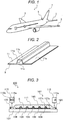
- FIG. 1 is a schematic perspective view of an aircraft 1.
- the aircraft 1 includes main wings 3, horizontal stabilizers 5, and a vertical stabilizer 7.
- the main wings 3, the horizontal stabilizers 5, and the vertical stabilizer 7 may be simply referred to as wings.
- FIG. 2 is a perspective view illustrating a cross section of a part of the wings of the aircraft 1.
- the wings of the aircraft 1 include a skin 9 and a stringer 11.
- the skin 9 is an outer shell of the wings of the aircraft 1.
- the skin 9 has, for example, a flat plate shape.
- the stringer 11 is used as a reinforced material that reinforces the skin 9, and is attached to the skin 9.
- the stringer 11 includes coupling portions 11a coupled to the skin 9 and a protrusion 11b that protrudes away from the skin 9.
- the coupling portions 11a are closer to the skin 9 than the protrusion 11b.
- the protrusion 11b is farther from the skin 9 than the coupling portions 11a.
- a hollow portion 11c is formed between the protrusion 11b and the skin 9.
- the stringer 11 include a hat stringer having a hat shape and a corrugated stringer having a corrugated shape.
- FIG. 2 illustrates an example in which the stringer 11 is the hat stringer.
- the stringer 11 is not limited thereto.
- the stringer 11 may be the corrugated stringer.
- the corrugated stringer is shaped such that hat stringers shown in FIG. 2 are continuously arranged in the left and right directions in FIG. 2 .
- the skin 9 and the stringer 11 are formed of a composite material such as glass fiber reinforced plastics (GFRP) or carbon fiber reinforced plastics (CFRP).
- the composite materials (for example, the skin 9 and the stringer 11) are molded by a composite material molding device 100 which will be described below.
- FIG. 3 is a view illustrating the composite material molding device 100 according to the embodiment.
- the composite material molding device 100 manufactures the composite materials by the VaRTM technique.
- the composite material molding device 100 includes a molding die 101, a film material 103, seal materials 105, a fiber base material 107, jigs (cores) 109, resin distribution media 111, a resin supply unit 113, and a resin discharge unit 115.
- a space S is formed between the molding die 101 and the film material 103.
- the space S is sealed by the seal materials 105 disposed between the molding die 101 and the film material 103.
- the fiber base material 107, the jigs 109, and the resin distribution media 111 are disposed in the space S.
- the fiber base material 107 is placed on the molding die 101.
- the fiber base material 107 is formed by stacking fiber materials such as glass fibers or carbon fibers.
- the fiber base material 107 includes a fiber base material 107a corresponding to the skin 9 (hereinafter referred to as a skin fiber base material) and a fiber base material 107b corresponding to the stringer 11 (hereinafter referred to as a stringer fiber base material).
- the skin fiber base material 107a has a shape approximate to the shape of the skin 9, and has, for example, a flat plate shape.
- the stringer fiber base material 107b has a shape approximate to the shape of the stringer 11, and has, for example, a corrugated shape.
- the skin fiber base material 107a is placed on the molding die 101, and the stringer fiber base material 107b is placed on the skin fiber base material 107a.
- the jigs 109 are disposed between the skin fiber base material 107a and the stringer fiber base material 107b.
- the jigs 109 have an outer shape approximate to the outer shape of the hollow portion 11c (see FIG. 2 ) formed between the skin 9 and the protrusion 11b of the stringer 11.
- the jigs 109 maintain the shape of the protrusion 11b (see FIG. 2 ) after the stringer 11 is molded. Therefore, the outer shape of each jig 109 is identical with an inner surface shape of the protrusion 11b of the stringer 11.
- the jigs 109 extend in a depth direction in FIG. 3 .
- the jigs 109 are placed on the skin fiber base material 107a, and the stringer fiber base material 107b is placed on the jigs 109. That is, the jigs 109 are disposed between the skin fiber base material 107a and the stringer fiber base material 107b.
- the resin distribution media 111 are placed on the fiber base material 107 (that is, the stringer fiber base material 107b).
- a polyethylene net is used as the resin distribution media 111. Supplied resin is uniformly distributed in the space S via the resin distribution media 111.
- the resin supply unit 113 and the resin discharge unit 115 are coupled to the space S sealed by the seal materials 105.
- the resin supply unit 113 includes a resin supply tank 113a that stores resin.
- the resin supply unit 113 supplies the resin stored in the resin supply tank 113a into the space S.
- the resin discharge unit 115 includes a vacuum pump 115a that suctions air and evacuates the space S, and a resin discharge tank 115b that stores the resin.
- the vacuum pump 115a suctions the air and resin in the space S.
- the resin (that is, surplus resin) suctioned from the space S is discharged to the resin discharge tank 115b.
- the resin is thermosetting resin.
- the resin may be thermoplastic resin.
- the plurality of jigs 109 are disposed along a flowing direction of the resin (hereinafter, referred to as a resin flowing direction).
- a longitudinal direction (that is, an extending direction) of the jigs 109 intersects the resin flowing direction.
- the longitudinal direction of the jigs 109 may be orthogonal to the resin flowing direction.
- the longitudinal direction of the jigs 109 may be parallel to the resin flowing direction.
- a user places the skin fiber base material 107a on the molding die 101, and places the jigs 109 on the skin fiber base material 107a. Further, the user places the stringer fiber base material 107b on the jigs 109, and places the resin distribution media 111 on the stringer fiber base material 107b.
- the user covers the resin distribution media 111 with the film material 103, and provides the sealing materials 105 between the film material 103 and the molding die 101 so as to enclose the resin distribution media 111 and the fiber base material 107. Accordingly, the sealed space S is formed between the film material 103 and the molding die 101, and the resin distribution media 111, the fiber base material 107, and the jigs 109 are accommodated in the space S.
- the user couples the resin supply unit 113 and the resin discharge unit 115 to the space S.
- the resin discharge unit 115 drives the vacuum pump 115a.
- the vacuum pump 115a suctions air in the space S to evacuate the space S.
- the resin stored in the resin supply tank 113a is supplied into the space S.
- the resin supplied into the space S is distributed via the resin distribution media 111 throughout the fiber base material 107.
- the resin distributed via the resin distribution media 111 is first introduced onto the stringer fiber base material 107b.
- the stringer fiber base material 107b is impregnated with the resin distributed via the resin distribution media 111.
- the resin is introduced onto the skin fiber base material 107a.
- the skin fiber base material 107a is impregnated with the resin that passes through the stringer fiber base material 107b.
- a surplus of the resin that impregnates the skin fiber base material 107a and the stringer fiber base material 107b is discharged into the resin discharge tank 115b of the resin discharge unit 115.
- the composite material molding device 100 is heated by a heating device (not illustrated).
- the resin is cured when heated by the heating device (not illustrated).
- the composite materials are integrally molded by curing the resin . That is, the molded composite materials (the skin 9 and the stringer 11) are permanently affixed to each other.
- the jigs 109 form the protrusion 11b of the stringer 11.
- the jigs 109 are pulled out from between the skin 9 and the stringer 11. Accordingly, as illustrated in FIG. 2 , the hollow portion 11c is formed between the skin 9 and the protrusion 11b of the stringer 11.
- the skin 9 and the stringer 11 are formed by impregnating the fiber base material 107 with the resin. If the fiber base material 107 is not sufficiently impregnated with the resin, a part of the molded composite materials may have low rigidity. Therefore, a resin impregnation sensor is provided in the composite material molding device 100. The resin impregnation sensor measures whether the fiber base material 107 is impregnated with the resin.
- a resin impregnation sensor is provided outside the composite material molding device 100.
- the stringer fiber base material 107b is impregnated with the resin from a resin distribution media 111 side towards the jigs 109. Therefore, it is difficult for the resin impregnation sensor of the related art to measure whether the fiber base material 107 is sufficiently impregnated up to the boundary between the stringer fiber base material 107b and the jigs 109 with the resin. That is, the resin impregnation sensor of the related art has poor measurement accuracy in measuring whether the fiber base material 107 is impregnated with the resin.
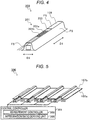
- FIG. 4 is a schematic perspective view of the resin impregnation measurement device 200.
- the resin impregnation measurement device 200 includes the jig 109, a resin impregnation sensor 201, and a mold release member 203.
- the mold release member 203 includes, for example, an insulator.
- the jig 109 includes outer surfaces including facing surfaces FS that are to face the stringer fiber base material 107b (see FIG. 3 ).
- the resin impregnation sensor 201 is disposed on any of the facing surface FS.
- the jig 109 includes outer surfaces including facing surfaces FS that are to face inner surfaces of the protrusion 11b (see FIG. 2 ) of the stringer 11.
- the resin impregnation sensor 201 is disposed on any of the facing surfaces FS.
- the resin impregnation sensor 201 includes a positive electrode 201a and a negative electrode 201b.
- a chain line indicates a power supply line that supplies power to the positive electrode 201a
- a broken line indicates a power supply line that supplies power to the negative electrode 201b.
- the positive electrode 201a and the negative electrode 201b are separated from each other and are disposed in parallel.
- the positive electrode 201a and the negative electrode 201b extend in a longitudinal direction D1 of the jig 109 (that is, a direction intersecting the resin flowing direction).
- the positive electrode 201a and the negative electrode 201b may extend in a short direction D2 of the jig 109 (that is, a direction parallel to the resin flowing direction).
- the positive electrode 201a is disposed on the right side in FIG. 4 and the negative electrode 201b is disposed on the left side in FIG. 4 .
- the disclosure is not limited to this example.
- the positive electrode 201a may be disposed on the left side in FIG. 4
- the negative electrode 201b may be disposed on the right side in FIG. 4 .
- the resin impregnation sensor 201 includes a facing surface that faces the jig 109.
- the facing surface of the resin impregnation sensor 201 is a contact surface of the resin impregnation sensor 201 that is in contact with the jig 109.
- the mold release member 203 is disposed on an opposite side to the facing surface of the resin impregnation sensor 201.
- the mold release member 203 covers the positive electrode 201a and the negative electrode 201b.
- the mold release member 203 prevents the resin from coming into contact with the positive electrode 201a and the negative electrode 201b. Therefore, the positive electrode 201a and the negative electrode 201b are less likely to be caught in the protrusion 11b of the stringer 11 after the composite material is molded.
- the resin impregnation measurement device 200 allows easily removing (pulling out) the positive electrode 201a and the negative electrode 201b from the molded composite materials, together with the jigs 109.
- FIG. 5 is a view illustrating a schematic configuration of a resin impregnation measurement system 300.
- the resin impregnation measurement system 300 includes a plurality of resin impregnation measurement devices 200 and a central controller 301.
- the central controller 301 is implemented by a semiconductor integrated circuit that includes a central processing unit (CPU), a ROM storing programs, a RAM serving as a working area.
- the central controller 301 manages and controls the entire resin impregnation measurement system 300.
- the central controller 301 also functions as a measurement controller 303 and an impregnation ratio deriving unit 305, in cooperation with the programs.
- the measurement controller 303 measures an electrostatic capacity between the positive electrode 201a and the negative electrode 201b (see FIG. 4 ) in each of the resin impregnation measurement devices 200.
- the measurement controller 303 applies a positive voltage to the positive electrode 201a and applies a negative voltage to the negative electrode 201b.
- a potential difference V between the voltage of the positive electrode 201a and the voltage of the negative electrode 201b is, for example, 5V.
- the measurement controller 303 obtains an electrostatic capacity value C 0 based on the dielectric constant ⁇ 0 of vacuum as a measurement result.
- the measurement controller 303 obtains an electrostatic capacity value C S based on the dielectric constant ⁇ S of the resin as a measurement result.
- the measurement controller 303 obtains a value between the value C 0 and the value C S according to the resin filling ratio (that is, an impregnation ratio).
- the electrostatic capacity has a relationship that the value C 0 ⁇ the value C S .
- the electrostatic capacity is measured by applying the positive voltage to the positive electrode 201a and applying the negative voltage to the negative electrode 201b.
- a method for measuring the electrostatic capacity is not limited thereto.
- the resin impregnation sensor 201 may include a pair of electrodes, and the electrostatic capacity may be measured by applying an AC voltage to the pair of electrodes.
- the impregnation ratio deriving unit 305 derives a resin impregnation ratio in the boundary between the fiber base material 107 (that is, the stringer fiber base material 107b) and the jigs 109 based on the electrostatic capacities measured by the measurement controller 303.
- the impregnation ratio deriving unit 305 can derive a resin impregnation ratio in the boundary between the fiber base material 107 and the jigs 109 (in a range of 0% to 100%) based on the electrostatic capacities measured by the measurement controller 303.
- the impregnation ratio deriving unit 305 can know that the filling in the boundary between the fiber base material 107 and the jigs 109 is finished (that is, the impregnation ratio is 100%).
- the resin impregnation measurement device 200 of the embodiment includes the resin impregnation sensors 201 on the jigs 109.
- the impregnation ratio deriving unit 305 can derive the impregnation ratio of the resin in the boundary between the stringer fiber base material 107b and the jigs 109. Therefore, the resin impregnation measurement device 200 of the embodiment can measure whether the fiber base material 107 is sufficiently impregnated up to the boundary between the stringer fiber base material 107b and the jigs 109 with the resin. That is, the resin impregnation measurement device 200 can improve measurement accuracy in measuring whether the fiber base material 107 is impregnated with the resin.
- the resin impregnation measurement device 200 of the embodiment includes the mold release members 203 that cover the resin impregnation sensors 201, on the jigs 109. This configuration allows keeping the resin impregnation sensors 201 separated from the resin. Therefore, the resin impregnation measurement device 200 of the embodiment allows easily removing the resin impregnation sensors 201 from the composite materials after the composite materials are molded.
- the resin impregnation sensors 201 are left in the composite materials (that is, the skin 9 and the stringer 11), there is room for improvement in that a crack might occur in the skin 9 and the stringer 11. That is, if the resin impregnation sensors 201 are left in the composite materials, there is room for improvement in quality of the composite materials.
- the resin impregnation sensors 201 can be easily removed from the composite materials together with the jigs 109. Therefore, the resin impregnation measurement device 200 of the embodiment can prevent cracks from occurring in the composite materials (that is, the skin 9 and the stringer 11) . As a result, a deterioration in quality of the composite materials can be prevented.
- a program that causes a computer to function as the central controller 301 of the resin impregnation measurement system 300, and a storage medium such as a computer readable flexible disk, a magneto-optical disk, a ROM, a CD, a DVD, or a BD that stores the program are provided.
- the program refers to a data processing method described in any language or description method.
- each resin impregnation sensor 201 includes electrodes (that is, the positive electrode 201a and the negative electrode 201b).
- the disclosure is not limited to this example.
- each resin impregnation sensor 201 may be implemented by, for example, an optical fiber sensor.
- an optical fiber is attached to each jig 109 in FIG. 4 .
- the measurement controller 303 causes light to enter from an incident end of each optical fiber, and measures Brillouin scattered light that returns to the incident end.
- the frequency of the Brillouin scattered light is shifted according to the filling ratio (that is, the impregnation ratio) of the resin.
- the impregnation ratio deriving unit 305 derives the impregnation ratio of the resin in the boundary between the stringer fiber base material 107b and the jigs 109 based on the frequency shift of the Brillouin scattered light.
- each resin impregnation sensor 201 is disposed on any of the facing surface FS of the corresponding jig 109 among the outer surfaces of the jig 109.
- the disclosure is not limited to this example.
- each resin impregnation sensor 201 may be disposed, for example, on a facing surface of the corresponding jig 109 that is to face the skin fiber base material 107a (that is, the skin 9) among the outer surfaces of the corresponding jig 109.
- FIG. 6 is a view illustrating a composite material molding device 100A according to a first modification.
- the composite material molding device 100A of the first modification is the same as the composite material molding device 100 of the above embodiment except that the skin fiber base material 107a is the skin 9.
- the skin 9, the jigs 109, the fiber base material 107 (that is, the stringer fiber base material 107b), and the resin distribution media 111 are accommodated in the space S.
- the skin 9 is placed on the molding die 101.
- the jigs 109 and the stringer fiber base material 107b are placed on the skin 9.
- the resin distribution media 111 is placed on the stringer fiber base material 107b. In this state, when the resin is filled and cured in the space S, a composite material (that is the stringer 11) is molded on the skin 9.
- FIG. 7 is a view illustrating a composite material molding device 100B according to a second modification.
- the composite material molding device 100B of the second modification is the same as the composite material molding device 100 of the above embodiment and the composite material molding device 100A of the first modification except that neither the skin fiber base material 107a nor the skin 9 is provided in the space S.
- the jigs 109, the fiber base material 107 that is, the stringer fiber base material 107b
- the resin distribution media 111 are accommodated in the space S.
- the jigs 109 and the stringer fiber base material 107b are placed on the molding die 101.
- the resin distribution media 111 is placed on the stringer fiber base material 107b. In this state, when the resin is filled and cured in the space S, a composite material (that is, the stringer 11) is molded on the molding die 101.
Landscapes
- Engineering & Computer Science (AREA)
- Mechanical Engineering (AREA)
- Physics & Mathematics (AREA)
- Power Engineering (AREA)
- Composite Materials (AREA)
- Chemical & Material Sciences (AREA)
- Thermal Sciences (AREA)
- Fluid Mechanics (AREA)
- General Physics & Mathematics (AREA)
- Electromagnetism (AREA)
- Architecture (AREA)
- Civil Engineering (AREA)
- Structural Engineering (AREA)
- Moulding By Coating Moulds (AREA)
- Reinforced Plastic Materials (AREA)
Abstract
Description
- The present application claims priority from Japanese Patent Application No.
2018-246725 filed on December 28, 2018 - The disclosure relates to a resin impregnation measurement device.
- Composite materials such as carbon fiber reinforced plastics (CFRP) are used in aircrafts. Japanese Unexamined Patent Application Publication (
JP-A) No. 2013-75471 - An aspect of the disclosure provides a resin impregnation measurement device. The device includes a jig and a resin impregnation sensor. The jig formed into an inner surface shape of a protrusion of a stringer. The jig includes outer surfaces including a facing surface that is to face an inner surface of the protrusion. The resin impregnation sensor is disposed on the facing surface of the jig.
- The accompanying drawings are included to provide a further understanding of the disclosure and are incorporated in and constitute a part of this specification. The drawings illustrate example embodiments and, together with the specification, serve to explain the principles of the disclosure.
-
FIG. 1 is a schematic perspective view of an aircraft. -
FIG. 2 is a perspective view illustrating a cross section of a part of a wing of the aircraft. -
FIG. 3 is a view illustrating a composite material molding device according to an embodiment of the disclosure. -
FIG. 4 is a schematic perspective view of a resin impregnation measurement device. -
FIG. 5 is a view illustrating a schematic configuration of the resin impregnation measurement system. -
FIG. 6 is a view illustrating a composite material molding device according to a first modification. -
FIG. 7 is a view illustrating a composite material molding device according to a second modification. - When the fiber base material is not sufficiently impregnated with resin, a part of the molded composite material is not impregnated with resin and may have low rigidity. Therefore, a composite material molding device disclosed in
JP-A No. 2013-75471 - However, the resin impregnation sensor is provided outside the composite material molding device. Since resin distribution media are usually provided inside the composite material molding device, the resin impregnation sensor has poor measurement accuracy in measuring whether the fiber base material is impregnated with resin.
- It is desirable to provide a resin impregnation measurement device capable of improving measurement accuracy in measuring whether a fiber base material is impregnated with resin.
- In the following, some embodiments of the disclosure are described in detail with reference to the accompanying drawings . Note that the following description is directed to illustrative examples of the disclosure and not to be construed as limiting to the disclosure. Factors including, without limitation, numerical values, shapes, materials, components, positions of the components, and how the components are coupled to each other are illustrative only and not to be construed as limiting to the disclosure. Further, elements in the following example embodiments which are not recited in a most-generic independent claim of the disclosure are optional and may be provided on an as-needed basis. The drawings are schematic and are not intended to be drawn to scale. Throughout the present specification and the drawings, elements having substantially the same function and configuration are denoted with the same numerals to avoid any redundant description.
-
FIG. 1 is a schematic perspective view of an aircraft 1. As illustrated inFIG. 1 , the aircraft 1 includesmain wings 3,horizontal stabilizers 5, and avertical stabilizer 7. Hereinafter, themain wings 3, thehorizontal stabilizers 5, and thevertical stabilizer 7 may be simply referred to as wings.FIG. 2 is a perspective view illustrating a cross section of a part of the wings of the aircraft 1. As illustrated inFIG. 2 , the wings of the aircraft 1 include askin 9 and astringer 11. - The
skin 9 is an outer shell of the wings of the aircraft 1. Theskin 9 has, for example, a flat plate shape. Thestringer 11 is used as a reinforced material that reinforces theskin 9, and is attached to theskin 9. Thestringer 11 includescoupling portions 11a coupled to theskin 9 and aprotrusion 11b that protrudes away from theskin 9. Thecoupling portions 11a are closer to theskin 9 than theprotrusion 11b. Theprotrusion 11b is farther from theskin 9 than thecoupling portions 11a. - A
hollow portion 11c is formed between theprotrusion 11b and theskin 9. Examples of thestringer 11 include a hat stringer having a hat shape and a corrugated stringer having a corrugated shape.FIG. 2 illustrates an example in which thestringer 11 is the hat stringer. Thestringer 11 is not limited thereto. Alternatively, thestringer 11 may be the corrugated stringer. Here, the corrugated stringer is shaped such that hat stringers shown inFIG. 2 are continuously arranged in the left and right directions inFIG. 2 . Theskin 9 and thestringer 11 are formed of a composite material such as glass fiber reinforced plastics (GFRP) or carbon fiber reinforced plastics (CFRP). The composite materials (for example, theskin 9 and the stringer 11) are molded by a compositematerial molding device 100 which will be described below. -
FIG. 3 is a view illustrating the compositematerial molding device 100 according to the embodiment. The compositematerial molding device 100 manufactures the composite materials by the VaRTM technique. As illustrated inFIG. 3 , the compositematerial molding device 100 includes a molding die 101, afilm material 103,seal materials 105, afiber base material 107, jigs (cores) 109,resin distribution media 111, aresin supply unit 113, and aresin discharge unit 115. - A space S is formed between the molding die 101 and the
film material 103. The space S is sealed by theseal materials 105 disposed between the molding die 101 and thefilm material 103. Thefiber base material 107, thejigs 109, and theresin distribution media 111 are disposed in the space S. - The
fiber base material 107 is placed on the molding die 101. Thefiber base material 107 is formed by stacking fiber materials such as glass fibers or carbon fibers. Thefiber base material 107 includes afiber base material 107a corresponding to the skin 9 (hereinafter referred to as a skin fiber base material) and afiber base material 107b corresponding to the stringer 11 (hereinafter referred to as a stringer fiber base material). - The skin
fiber base material 107a has a shape approximate to the shape of theskin 9, and has, for example, a flat plate shape. The stringerfiber base material 107b has a shape approximate to the shape of thestringer 11, and has, for example, a corrugated shape. The skinfiber base material 107a is placed on the molding die 101, and the stringerfiber base material 107b is placed on the skinfiber base material 107a. - The
jigs 109 are disposed between the skinfiber base material 107a and the stringerfiber base material 107b. Thejigs 109 have an outer shape approximate to the outer shape of thehollow portion 11c (seeFIG. 2 ) formed between theskin 9 and theprotrusion 11b of thestringer 11. Thejigs 109 maintain the shape of theprotrusion 11b (seeFIG. 2 ) after thestringer 11 is molded. Therefore, the outer shape of eachjig 109 is identical with an inner surface shape of theprotrusion 11b of thestringer 11. Thejigs 109 extend in a depth direction inFIG. 3 . Thejigs 109 are placed on the skinfiber base material 107a, and the stringerfiber base material 107b is placed on thejigs 109. That is, thejigs 109 are disposed between the skinfiber base material 107a and the stringerfiber base material 107b. - The
resin distribution media 111 are placed on the fiber base material 107 (that is, the stringerfiber base material 107b). For example, a polyethylene net is used as theresin distribution media 111. Supplied resin is uniformly distributed in the space S via theresin distribution media 111. - The
resin supply unit 113 and theresin discharge unit 115 are coupled to the space S sealed by theseal materials 105. Theresin supply unit 113 includes a resin supply tank 113a that stores resin.
Theresin supply unit 113 supplies the resin stored in the resin supply tank 113a into the space S. - The
resin discharge unit 115 includes avacuum pump 115a that suctions air and evacuates the space S, and aresin discharge tank 115b that stores the resin. Thevacuum pump 115a suctions the air and resin in the space S. The resin (that is, surplus resin) suctioned from the space S is discharged to theresin discharge tank 115b. - In the embodiment, the resin is thermosetting resin. The disclosure is not limited thereto. For example, the resin may be thermoplastic resin. When the resin is supplied into the space S, the resin flows from the
resin supply unit 113 side (right side inFIG. 3 ) toward theresin discharge unit 115 side (left side inFIG. 3 ). The plurality ofjigs 109 are disposed along a flowing direction of the resin (hereinafter, referred to as a resin flowing direction). A longitudinal direction (that is, an extending direction) of thejigs 109 intersects the resin flowing direction. The longitudinal direction of thejigs 109 may be orthogonal to the resin flowing direction. The disclosure is not limited thereto. Alternatively, the longitudinal direction of thejigs 109 may be parallel to the resin flowing direction. - Next, a method for molding the composite materials using the composite
material molding device 100 will be described. First, a user places the skinfiber base material 107a on the molding die 101, and places thejigs 109 on the skinfiber base material 107a. Further, the user places the stringerfiber base material 107b on thejigs 109, and places theresin distribution media 111 on the stringerfiber base material 107b. - Next, the user covers the
resin distribution media 111 with thefilm material 103, and provides the sealingmaterials 105 between thefilm material 103 and the molding die 101 so as to enclose theresin distribution media 111 and thefiber base material 107. Accordingly, the sealed space S is formed between thefilm material 103 and the molding die 101, and theresin distribution media 111, thefiber base material 107, and thejigs 109 are accommodated in the space S. - Thereafter, the user couples the
resin supply unit 113 and theresin discharge unit 115 to the space S.
When theresin supply unit 113 and theresin discharge unit 115 are coupled to the space S, theresin discharge unit 115 drives thevacuum pump 115a. Thevacuum pump 115a suctions air in the space S to evacuate the space S. When the space S is in the vacuum state, the resin stored in the resin supply tank 113a is supplied into the space S. - The resin supplied into the space S is distributed via the
resin distribution media 111 throughout thefiber base material 107. The resin distributed via theresin distribution media 111 is first introduced onto the stringerfiber base material 107b. The stringerfiber base material 107b is impregnated with the resin distributed via theresin distribution media 111. - When the stringer
fiber base material 107b is impregnated with the resin, the resin is introduced onto the skinfiber base material 107a. The skinfiber base material 107a is impregnated with the resin that passes through the stringerfiber base material 107b. A surplus of the resin that impregnates the skinfiber base material 107a and the stringerfiber base material 107b is discharged into theresin discharge tank 115b of theresin discharge unit 115. - When the fiber base material 107 (including the skin
fiber base material 107a and the stringerfiber base material 107b) is impregnated with the resin, the compositematerial molding device 100 is heated by a heating device (not illustrated). The resin is cured when heated by the heating device (not illustrated). The composite materials (theskin 9 and the stringer 11) are integrally molded by curing the resin . That is, the molded composite materials (theskin 9 and the stringer 11) are permanently affixed to each other. During the resin curing process, thejigs 109 form theprotrusion 11b of thestringer 11. - After the composite materials are molded, the
jigs 109 are pulled out from between theskin 9 and thestringer 11. Accordingly, as illustrated inFIG. 2 , thehollow portion 11c is formed between theskin 9 and theprotrusion 11b of thestringer 11. - In this way, the
skin 9 and thestringer 11 are formed by impregnating thefiber base material 107 with the resin. If thefiber base material 107 is not sufficiently impregnated with the resin, a part of the molded composite materials may have low rigidity. Therefore, a resin impregnation sensor is provided in the compositematerial molding device 100. The resin impregnation sensor measures whether thefiber base material 107 is impregnated with the resin. - In a related art, a resin impregnation sensor is provided outside the composite
material molding device 100. The stringerfiber base material 107b is impregnated with the resin from aresin distribution media 111 side towards thejigs 109. Therefore, it is difficult for the resin impregnation sensor of the related art to measure whether thefiber base material 107 is sufficiently impregnated up to the boundary between the stringerfiber base material 107b and thejigs 109 with the resin. That is, the resin impregnation sensor of the related art has poor measurement accuracy in measuring whether thefiber base material 107 is impregnated with the resin. - Then, the resin impregnation sensor is provided on the
jigs 109 in the embodiment. Hereinafter, thejig 109 provided with the resin impregnation sensor will be referred to as a resinimpregnation measurement device 200.FIG. 4 is a schematic perspective view of the resinimpregnation measurement device 200. As illustrated inFIG. 4 , the resinimpregnation measurement device 200 includes thejig 109, aresin impregnation sensor 201, and amold release member 203. Themold release member 203 includes, for example, an insulator. - The
jig 109 includes outer surfaces including facing surfaces FS that are to face the stringerfiber base material 107b (seeFIG. 3 ). Theresin impregnation sensor 201 is disposed on any of the facing surface FS. For example, thejig 109 includes outer surfaces including facing surfaces FS that are to face inner surfaces of theprotrusion 11b (seeFIG. 2 ) of thestringer 11. Theresin impregnation sensor 201 is disposed on any of the facing surfaces FS. - The
resin impregnation sensor 201 includes a positive electrode 201a and anegative electrode 201b. InFIG. 4 , a chain line indicates a power supply line that supplies power to the positive electrode 201a, and a broken line indicates a power supply line that supplies power to thenegative electrode 201b. The positive electrode 201a and thenegative electrode 201b are separated from each other and are disposed in parallel. The positive electrode 201a and thenegative electrode 201b extend in a longitudinal direction D1 of the jig 109 (that is, a direction intersecting the resin flowing direction). Alternatively, the positive electrode 201a and thenegative electrode 201b may extend in a short direction D2 of the jig 109 (that is, a direction parallel to the resin flowing direction). In the embodiment, the positive electrode 201a is disposed on the right side inFIG. 4 and thenegative electrode 201b is disposed on the left side inFIG. 4 . The disclosure is not limited to this example. Alternatively, the positive electrode 201a may be disposed on the left side inFIG. 4 , and thenegative electrode 201b may be disposed on the right side inFIG. 4 . - The
resin impregnation sensor 201 includes a facing surface that faces thejig 109. The facing surface of theresin impregnation sensor 201 is a contact surface of theresin impregnation sensor 201 that is in contact with thejig 109. Themold release member 203 is disposed on an opposite side to the facing surface of theresin impregnation sensor 201. Themold release member 203 covers the positive electrode 201a and thenegative electrode 201b. Themold release member 203 prevents the resin from coming into contact with the positive electrode 201a and thenegative electrode 201b. Therefore, the positive electrode 201a and thenegative electrode 201b are less likely to be caught in theprotrusion 11b of thestringer 11 after the composite material is molded. As a result, the resinimpregnation measurement device 200 allows easily removing (pulling out) the positive electrode 201a and thenegative electrode 201b from the molded composite materials, together with thejigs 109. -
FIG. 5 is a view illustrating a schematic configuration of a resinimpregnation measurement system 300. As illustrated inFIG. 5 , the resinimpregnation measurement system 300 includes a plurality of resinimpregnation measurement devices 200 and acentral controller 301. - The
central controller 301 is implemented by a semiconductor integrated circuit that includes a central processing unit (CPU), a ROM storing programs, a RAM serving as a working area. Thecentral controller 301 manages and controls the entire resinimpregnation measurement system 300. Thecentral controller 301 also functions as ameasurement controller 303 and an impregnationratio deriving unit 305, in cooperation with the programs. - The
measurement controller 303 measures an electrostatic capacity between the positive electrode 201a and thenegative electrode 201b (seeFIG. 4 ) in each of the resinimpregnation measurement devices 200. Themeasurement controller 303 applies a positive voltage to the positive electrode 201a and applies a negative voltage to thenegative electrode 201b. A potential difference V between the voltage of the positive electrode 201a and the voltage of thenegative electrode 201b is, for example, 5V. At this time, when the resin is filled between the positive electrode 201a and thenegative electrode 201b, a dielectric constant between the positive electrode 201a and thenegative electrode 201b changes as compared to a state in which no resin is filled. When the dielectric constant changes, a value of the electrostatic capacity measured by themeasurement controller 303 changes. - For example, when no resin is filled between the positive electrode 201a and the
negative electrode 201b (an unfilled state, that is, a filling ratio is 0%), themeasurement controller 303 obtains an electrostatic capacity value C0 based on the dielectric constant ε0 of vacuum as a measurement result. When the resin is filled between the positive electrode 201a and thenegative electrode 201b (that is, the filling ratio is 100%), themeasurement controller 303 obtains an electrostatic capacity value CS based on the dielectric constant εS of the resin as a measurement result. While the space between the positive electrode 201a and thenegative electrode 201b is changing from the unfilled state to a filled state, themeasurement controller 303 obtains a value between the value C0 and the value CS according to the resin filling ratio (that is, an impregnation ratio). In general, the electrostatic capacity has a relationship that the value C0 < the value CS. In the embodiment, the electrostatic capacity is measured by applying the positive voltage to the positive electrode 201a and applying the negative voltage to thenegative electrode 201b. A method for measuring the electrostatic capacity is not limited thereto. For example, theresin impregnation sensor 201 may include a pair of electrodes, and the electrostatic capacity may be measured by applying an AC voltage to the pair of electrodes. - The impregnation
ratio deriving unit 305 derives a resin impregnation ratio in the boundary between the fiber base material 107 (that is, the stringerfiber base material 107b) and thejigs 109 based on the electrostatic capacities measured by themeasurement controller 303. The impregnationratio deriving unit 305 can derive a resin impregnation ratio in the boundary between thefiber base material 107 and the jigs 109 (in a range of 0% to 100%) based on the electrostatic capacities measured by themeasurement controller 303. For example, when the electrostatic capacity is the value CS, the impregnationratio deriving unit 305 can know that the filling in the boundary between thefiber base material 107 and thejigs 109 is finished (that is, the impregnation ratio is 100%). - As described above, the resin
impregnation measurement device 200 of the embodiment includes theresin impregnation sensors 201 on thejigs 109. With this configuration, the impregnationratio deriving unit 305 can derive the impregnation ratio of the resin in the boundary between the stringerfiber base material 107b and thejigs 109. Therefore, the resinimpregnation measurement device 200 of the embodiment can measure whether thefiber base material 107 is sufficiently impregnated up to the boundary between the stringerfiber base material 107b and thejigs 109 with the resin. That is, the resinimpregnation measurement device 200 can improve measurement accuracy in measuring whether thefiber base material 107 is impregnated with the resin. - Further, the resin
impregnation measurement device 200 of the embodiment includes themold release members 203 that cover theresin impregnation sensors 201, on thejigs 109. This configuration allows keeping theresin impregnation sensors 201 separated from the resin. Therefore, the resinimpregnation measurement device 200 of the embodiment allows easily removing theresin impregnation sensors 201 from the composite materials after the composite materials are molded. - If the
resin impregnation sensors 201 are left in the composite materials (that is, theskin 9 and the stringer 11), there is room for improvement in that a crack might occur in theskin 9 and thestringer 11. That is, if theresin impregnation sensors 201 are left in the composite materials, there is room for improvement in quality of the composite materials. In the embodiment, theresin impregnation sensors 201 can be easily removed from the composite materials together with thejigs 109. Therefore, the resinimpregnation measurement device 200 of the embodiment can prevent cracks from occurring in the composite materials (that is, theskin 9 and the stringer 11) . As a result, a deterioration in quality of the composite materials can be prevented. - The embodiment of the disclosure has been described above with reference to the accompanying drawings. It is needless to say that the disclosure is not limited to the present embodiment. It will be apparent to those skilled in the art that various changes and modifications may be made to the embodiment within the scope of the claims. It is to be understood that such changes and modifications also fall within the technical scope of the disclosure.
- For example, a program that causes a computer to function as the
central controller 301 of the resinimpregnation measurement system 300, and a storage medium such as a computer readable flexible disk, a magneto-optical disk, a ROM, a CD, a DVD, or a BD that stores the program are provided. Here, the program refers to a data processing method described in any language or description method. - In the above embodiment, the description has been made on the example in which a single (one) positive electrode 201a and a single (one)
negative electrode 201b extend in the longitudinal direction of eachjig 109. The disclosure is not limited to this example. Alternatively, plural positive electrodes 201a and pluralnegative electrodes 201b may extend in the longitudinal direction of eachjig 109. - In the above embodiment, the description has been made on the example in which each
resin impregnation sensor 201 includes electrodes (that is, the positive electrode 201a and thenegative electrode 201b). The disclosure is not limited to this example. Alternatively, eachresin impregnation sensor 201 may be implemented by, for example, an optical fiber sensor. For example, instead of the positive electrode 201a and thenegative electrode 201b, an optical fiber is attached to eachjig 109 inFIG. 4 . Themeasurement controller 303 causes light to enter from an incident end of each optical fiber, and measures Brillouin scattered light that returns to the incident end. When the boundary between the stringerfiber base material 107b and thejigs 109 is filled with the resin, the frequency of the Brillouin scattered light is shifted according to the filling ratio (that is, the impregnation ratio) of the resin. The impregnationratio deriving unit 305 derives the impregnation ratio of the resin in the boundary between the stringerfiber base material 107b and thejigs 109 based on the frequency shift of the Brillouin scattered light. - In the above embodiment, the description has been made on the example in which each
resin impregnation sensor 201 is disposed on any of the facing surface FS of thecorresponding jig 109 among the outer surfaces of thejig 109. The disclosure is not limited to this example. Alternatively, eachresin impregnation sensor 201 may be disposed, for example, on a facing surface of thecorresponding jig 109 that is to face the skinfiber base material 107a (that is, the skin 9) among the outer surfaces of thecorresponding jig 109. - In the above embodiment, the description has been made on the example in which the
skin 9 and thestringer 11 are integrally molded and permanently affixed to each other. The disclosure is not limited to this example. Alternatively, thestringer 11 may be molded separately from theskin 9.FIG. 6 is a view illustrating a composite material molding device 100A according to a first modification. The composite material molding device 100A of the first modification is the same as the compositematerial molding device 100 of the above embodiment except that the skinfiber base material 107a is theskin 9. - As illustrated in
FIG. 6 , theskin 9, thejigs 109, the fiber base material 107 (that is, the stringerfiber base material 107b), and theresin distribution media 111 are accommodated in the space S. Theskin 9 is placed on the molding die 101. Thejigs 109 and the stringerfiber base material 107b are placed on theskin 9. Theresin distribution media 111 is placed on the stringerfiber base material 107b. In this state, when the resin is filled and cured in the space S, a composite material (that is the stringer 11) is molded on theskin 9. -
FIG. 7 is a view illustrating a compositematerial molding device 100B according to a second modification. The compositematerial molding device 100B of the second modification is the same as the compositematerial molding device 100 of the above embodiment and the composite material molding device 100A of the first modification except that neither the skinfiber base material 107a nor theskin 9 is provided in the space S. As illustrated inFIG. 7 , thejigs 109, the fiber base material 107 (that is, the stringerfiber base material 107b), and theresin distribution media 111 are accommodated in the space S. Thejigs 109 and the stringerfiber base material 107b are placed on the molding die 101. Theresin distribution media 111 is placed on the stringerfiber base material 107b. In this state, when the resin is filled and cured in the space S, a composite material (that is, the stringer 11) is molded on the molding die 101. - According to at least one embodiment of the disclosure, it is possible to improve the measurement accuracy in measuring whether the fiber base material is impregnated with resin.
Claims (2)
- A resin impregnation measurement device comprising:a jig formed into an inner surface shape of a protrusion of a stringer, the jig comprising outer surfaces comprising a facing surface that is to face an inner surface of the protrusion; anda resin impregnation sensor disposed on the facing surface of the jig.
- The resin impregnation measurement device according to claim 1, further comprising a mold release member, wherein
the resin impregnation sensor comprises a facing surface that faces the jig, and
the mold release member is disposed on an opposite side to the facing surface of the resin impregnation sensor.
Applications Claiming Priority (1)
| Application Number | Priority Date | Filing Date | Title |
|---|---|---|---|
| JP2018246725A JP7161399B2 (en) | 2018-12-28 | 2018-12-28 | Resin impregnation measuring device |
Publications (2)
| Publication Number | Publication Date |
|---|---|
| EP3674069A1 true EP3674069A1 (en) | 2020-07-01 |
| EP3674069B1 EP3674069B1 (en) | 2021-09-15 |
Family
ID=68583188
Family Applications (1)
| Application Number | Title | Priority Date | Filing Date |
|---|---|---|---|
| EP19209434.0A Active EP3674069B1 (en) | 2018-12-28 | 2019-11-15 | Resin impregnation measurement device |
Country Status (4)
| Country | Link |
|---|---|
| US (1) | US11623374B2 (en) |
| EP (1) | EP3674069B1 (en) |
| JP (1) | JP7161399B2 (en) |
| CN (1) | CN111376501B (en) |
Families Citing this family (2)
| Publication number | Priority date | Publication date | Assignee | Title |
|---|---|---|---|---|
| ES2925907T3 (en) * | 2019-07-03 | 2022-10-20 | Airbus Operations Slu | Resin flow monitoring system |
| JP2025030426A (en) | 2023-08-23 | 2025-03-07 | 三菱重工業株式会社 | Inspection device and inspection system |
Citations (4)
| Publication number | Priority date | Publication date | Assignee | Title |
|---|---|---|---|---|
| EP1415782A1 (en) * | 2001-08-07 | 2004-05-06 | Toray Industries, Inc. | Method for producing upsized frp member |
| JP2013075471A (en) | 2011-09-30 | 2013-04-25 | Toray Ind Inc | Method and apparatus for forming fiber-reinforced plastic structure |
| US20140290840A1 (en) * | 2011-07-27 | 2014-10-02 | Heinz Bardenhagen | Device for the manufacture of a bonded component from fibre-reinforced plastics and also a method |
| US20140300021A1 (en) * | 2011-07-27 | 2014-10-09 | Airbus Operations Gmbh | Device for the manufacture of a bonded component from fibre-reinforced plastics and also a method |
Family Cites Families (43)
| Publication number | Priority date | Publication date | Assignee | Title |
|---|---|---|---|---|
| US2435866A (en) * | 1943-07-30 | 1948-02-10 | Paul H Bilhuber | Fluid-operated apparatus for producing molded articles |
| US4044600A (en) * | 1972-01-31 | 1977-08-30 | The Firestone Tire & Rubber Company | Tire cure and heat transfer simulator |
| US4486996A (en) * | 1982-05-19 | 1984-12-11 | Luis Alejos | Construction-panel prefabrication method, panels thus made and equipment for implementing said method |
| US5453291A (en) * | 1993-05-25 | 1995-09-26 | Honda Giken Kogyo Kabushiki Kaisha | FRP member and method of detecting internal damage therein |
| US5770155A (en) * | 1995-11-21 | 1998-06-23 | United Technologies Corporation | Composite structure resin cure monitoring apparatus using an optical fiber grating sensor |
| US6532799B2 (en) * | 2000-01-18 | 2003-03-18 | Florida State University Research Foundation | System for in-situ and on-line monitoring of a perform layup process for liquid composite molding |
| JP4727960B2 (en) * | 2004-09-06 | 2011-07-20 | 株式会社プライムポリマー | Method for producing fiber reinforced resin composition |
| JP4676735B2 (en) * | 2004-09-22 | 2011-04-27 | 東レ・ダウコーニング株式会社 | Optical semiconductor device manufacturing method and optical semiconductor device |
| US20080211145A1 (en) * | 2005-07-05 | 2008-09-04 | Quickstep Technologies Pty Ltd | Composite Component Production Using Fluid Density and Pressure |
| GB0622691D0 (en) * | 2006-11-14 | 2006-12-27 | Airbus Uk Ltd | Method and apparatus for controlling the geometry of a composite component |
| JP2008137179A (en) * | 2006-11-30 | 2008-06-19 | Toray Ind Inc | Manufacturing method of fiber reinforced plastic |
| DE102007015909A1 (en) * | 2007-04-02 | 2008-10-09 | Mt Aerospace Ag | Process for producing fiber-reinforced hollow bodies |
| US7861969B2 (en) * | 2007-05-24 | 2011-01-04 | The Boeing Company | Shaped composite stringers and methods of making |
| JP5151269B2 (en) | 2007-06-26 | 2013-02-27 | 横浜ゴム株式会社 | Manufacturing method and manufacturing apparatus for fiber reinforced plastic panel |
| US7879276B2 (en) * | 2007-11-08 | 2011-02-01 | The Boeing Company | Foam stiffened hollow composite stringer |
| US8196452B2 (en) * | 2008-03-27 | 2012-06-12 | The Boeing Company | Collection of process data using in-situ sensors |
| US8617687B2 (en) * | 2009-08-03 | 2013-12-31 | The Boeing Company | Multi-functional aircraft structures |
| DE102009029575B4 (en) * | 2009-09-18 | 2011-06-22 | Airbus Operations GmbH, 21129 | Method for stiffening a fiber composite component and arrangement for producing a stiffened fiber composite component |
| US8703268B2 (en) * | 2009-11-13 | 2014-04-22 | The Boeing Company | Morphing panel structure |
| US8556618B2 (en) * | 2011-04-07 | 2013-10-15 | Spirit Aerosystems, Inc. | Method and bladder apparatus for forming composite parts |
| US9969131B2 (en) * | 2011-06-22 | 2018-05-15 | The Boeing Company | Automated ply layup system |
| JP2013022835A (en) * | 2011-07-21 | 2013-02-04 | Mitsubishi Heavy Ind Ltd | Method and apparatus for producing at least two products including fiber-reinforced resin |
| US9056413B1 (en) * | 2012-06-07 | 2015-06-16 | The Boeing Company | Method and portable station for laying up and curing composite resin parts |
| EP2671708B1 (en) * | 2012-06-08 | 2017-02-01 | Airbus Operations GmbH | Method and system for leak detection in vacuum bagging |
| GB201215124D0 (en) * | 2012-08-24 | 2012-10-10 | Newton John R | A method of making a composite structure |
| JP5738816B2 (en) * | 2012-09-13 | 2015-06-24 | 住友ゴム工業株式会社 | Rubber sheet manufacturing apparatus and rubber sheet picking apparatus |
| US10239265B2 (en) * | 2013-03-15 | 2019-03-26 | Composites Intellectual Holdings, Inc. | Structural composite preform wet-out and curing system and method |
| DE112014005100B4 (en) * | 2013-11-07 | 2024-01-11 | AGC Inc. | Mold release film and method for producing a semiconductor package |
| WO2016003339A1 (en) * | 2014-07-03 | 2016-01-07 | Saab Ab | A composite article having multifunctional properties and method for its manufacture |
| JP6598477B2 (en) * | 2015-03-11 | 2019-10-30 | 株式会社Subaru | Composite material molding apparatus and composite material molding method |
| US10300634B2 (en) * | 2015-11-16 | 2019-05-28 | The Boeing Company | Advanced multiple grid heat sources to achieve optimized cure structure and method of making the same |
| WO2017103745A1 (en) * | 2015-12-17 | 2017-06-22 | Bombardier Inc. | Preform tool and method of shaping composite material |
| JP6346214B2 (en) * | 2016-03-24 | 2018-06-20 | 株式会社Subaru | Composite material forming jig, composite material forming method, ultrasonic inspection system, ultrasonic inspection method, and aircraft structure |
| DE102016210086B4 (en) | 2016-06-08 | 2025-11-13 | Airbus Operations Gmbh | Method for manufacturing a structural component for an aircraft or spacecraft, and arrangement |
| CN109715361A (en) * | 2016-09-14 | 2019-05-03 | 日产自动车株式会社 | The forming method and composite material of composite material |
| IT201600093472A1 (en) * | 2016-09-16 | 2018-03-16 | Afros Spa | METHOD AND INFUSION APPARATUS FOR THE PRODUCTION OF REINFORCED COMPOSITE MATERIAL BODIES |
| FR3056141A1 (en) * | 2016-09-20 | 2018-03-23 | Airbus Operations (S.A.S.) | PROCESS FOR MANUFACTURING A PIECE OF COMPOSITE MATERIAL |
| EP3521002B1 (en) | 2016-09-29 | 2023-11-01 | Subaru Corporation | Composite material structure and method for manufacturing composite material structure |
| KR20180071751A (en) * | 2016-12-20 | 2018-06-28 | 주식회사 효성 | Apparatus for measuring impregnation rate of resin |
| EP3489001B1 (en) * | 2017-11-22 | 2025-08-06 | Afros S.P.A. | Apparatus for fine and controlled adjustment of an injection molding process and related industrial process |
| DE102018206665A1 (en) * | 2018-04-30 | 2019-10-31 | Airbus Operations Gmbh | Structural component and system and method for the detection of damage |
| CN110873737B (en) * | 2018-09-03 | 2024-04-26 | 株式会社斯巴鲁 | Resin impregnation measurement system |
| JP7202258B2 (en) | 2018-09-03 | 2023-01-11 | 株式会社Subaru | Resin impregnation measurement system |
-
2018
- 2018-12-28 JP JP2018246725A patent/JP7161399B2/en active Active
-
2019
- 2019-11-13 CN CN201911107840.7A patent/CN111376501B/en active Active
- 2019-11-15 EP EP19209434.0A patent/EP3674069B1/en active Active
- 2019-12-18 US US16/718,406 patent/US11623374B2/en active Active
Patent Citations (4)
| Publication number | Priority date | Publication date | Assignee | Title |
|---|---|---|---|---|
| EP1415782A1 (en) * | 2001-08-07 | 2004-05-06 | Toray Industries, Inc. | Method for producing upsized frp member |
| US20140290840A1 (en) * | 2011-07-27 | 2014-10-02 | Heinz Bardenhagen | Device for the manufacture of a bonded component from fibre-reinforced plastics and also a method |
| US20140300021A1 (en) * | 2011-07-27 | 2014-10-09 | Airbus Operations Gmbh | Device for the manufacture of a bonded component from fibre-reinforced plastics and also a method |
| JP2013075471A (en) | 2011-09-30 | 2013-04-25 | Toray Ind Inc | Method and apparatus for forming fiber-reinforced plastic structure |
Also Published As
| Publication number | Publication date |
|---|---|
| EP3674069B1 (en) | 2021-09-15 |
| US11623374B2 (en) | 2023-04-11 |
| JP2020104443A (en) | 2020-07-09 |
| CN111376501A (en) | 2020-07-07 |
| US20200207037A1 (en) | 2020-07-02 |
| CN111376501B (en) | 2023-10-27 |
| JP7161399B2 (en) | 2022-10-26 |
Similar Documents
| Publication | Publication Date | Title |
|---|---|---|
| EP3476578B1 (en) | Composite forming jig and composite forming method | |
| EP3674069B1 (en) | Resin impregnation measurement device | |
| KR102266130B1 (en) | Radius fillers for composite structures, composite structures that include radius fillers, and systems and methods of forming the same | |
| US9108376B2 (en) | Method for making a wind turbine rotor blade half shell or wind turbine rotor blade and production mold therefor | |
| US8460502B2 (en) | Method and tooling for manufacture of co-cured composite structures | |
| US9623620B2 (en) | Three-dimensional reuseable curing caul for use in curing integrated composite components and methods of making the same | |
| US20100326584A1 (en) | Method and apparatus for detecting leak in a vartm process | |
| US9067345B2 (en) | Mold for manufacture of fiber composite parts and method of manufacture of fiber composite parts with such a mold | |
| CN110891752A (en) | Composite material forming jig and composite material forming method | |
| WO2014070381A1 (en) | System and method for manufacturing monolithic structures using expanding internal tools | |
| CN104149228B (en) | The integrated molding mould of a kind of fiberglass radome and forming method | |
| US20110206875A1 (en) | Method and arrangement for production of an integral hollow-profiled component with fibre composite material | |
| US20220152881A1 (en) | Multi-Segment Mandrel for Processing a Composite Part and Method for Fabricating a Composite Part | |
| US10882263B2 (en) | Method for impregnating a preform with resin utilizing a caul plate having a channel for distributing resin | |
| EP3616891B1 (en) | Resin impregnation measurement system | |
| JP7202258B2 (en) | Resin impregnation measurement system | |
| US11828730B2 (en) | Vacuum bag having integral ultrasonic transducers | |
| US20200238633A1 (en) | Production method of composite material | |
| KR102075425B1 (en) | Manufacturing apparatus and method for horizontal stabilizer of Light Civil Helicopter | |
| CN114536814A (en) | Baffle system for aircraft manufacturing | |
| JP2007021869A (en) | Molding jig | |
| US20200139650A1 (en) | Method of manufacturing a first cured part and a second cured part |
Legal Events
| Date | Code | Title | Description |
|---|---|---|---|
| PUAI | Public reference made under article 153(3) epc to a published international application that has entered the european phase |
Free format text: ORIGINAL CODE: 0009012 |
|
| STAA | Information on the status of an ep patent application or granted ep patent |
Free format text: STATUS: THE APPLICATION HAS BEEN PUBLISHED |
|
| AK | Designated contracting states |
Kind code of ref document: A1 Designated state(s): AL AT BE BG CH CY CZ DE DK EE ES FI FR GB GR HR HU IE IS IT LI LT LU LV MC MK MT NL NO PL PT RO RS SE SI SK SM TR |
|
| AX | Request for extension of the european patent |
Extension state: BA ME |
|
| STAA | Information on the status of an ep patent application or granted ep patent |
Free format text: STATUS: REQUEST FOR EXAMINATION WAS MADE |
|
| 17P | Request for examination filed |
Effective date: 20201223 |
|
| RBV | Designated contracting states (corrected) |
Designated state(s): AL AT BE BG CH CY CZ DE DK EE ES FI FR GB GR HR HU IE IS IT LI LT LU LV MC MK MT NL NO PL PT RO RS SE SI SK SM TR |
|
| GRAP | Despatch of communication of intention to grant a patent |
Free format text: ORIGINAL CODE: EPIDOSNIGR1 |
|
| STAA | Information on the status of an ep patent application or granted ep patent |
Free format text: STATUS: GRANT OF PATENT IS INTENDED |
|
| INTG | Intention to grant announced |
Effective date: 20210528 |
|
| GRAS | Grant fee paid |
Free format text: ORIGINAL CODE: EPIDOSNIGR3 |
|
| GRAA | (expected) grant |
Free format text: ORIGINAL CODE: 0009210 |
|
| STAA | Information on the status of an ep patent application or granted ep patent |
Free format text: STATUS: THE PATENT HAS BEEN GRANTED |
|
| AK | Designated contracting states |
Kind code of ref document: B1 Designated state(s): AL AT BE BG CH CY CZ DE DK EE ES FI FR GB GR HR HU IE IS IT LI LT LU LV MC MK MT NL NO PL PT RO RS SE SI SK SM TR |
|
| REG | Reference to a national code |
Ref country code: CH Ref legal event code: EP |
|
| REG | Reference to a national code |
Ref country code: DE Ref legal event code: R096 Ref document number: 602019007707 Country of ref document: DE |
|
| REG | Reference to a national code |
Ref country code: IE Ref legal event code: FG4D |
|
| REG | Reference to a national code |
Ref country code: AT Ref legal event code: REF Ref document number: 1430205 Country of ref document: AT Kind code of ref document: T Effective date: 20211015 |
|
| REG | Reference to a national code |
Ref country code: LT Ref legal event code: MG9D |
|
| REG | Reference to a national code |
Ref country code: NL Ref legal event code: MP Effective date: 20210915 |
|
| PG25 | Lapsed in a contracting state [announced via postgrant information from national office to epo] |
Ref country code: HR Free format text: LAPSE BECAUSE OF FAILURE TO SUBMIT A TRANSLATION OF THE DESCRIPTION OR TO PAY THE FEE WITHIN THE PRESCRIBED TIME-LIMIT Effective date: 20210915 Ref country code: FI Free format text: LAPSE BECAUSE OF FAILURE TO SUBMIT A TRANSLATION OF THE DESCRIPTION OR TO PAY THE FEE WITHIN THE PRESCRIBED TIME-LIMIT Effective date: 20210915 Ref country code: NO Free format text: LAPSE BECAUSE OF FAILURE TO SUBMIT A TRANSLATION OF THE DESCRIPTION OR TO PAY THE FEE WITHIN THE PRESCRIBED TIME-LIMIT Effective date: 20211215 Ref country code: LT Free format text: LAPSE BECAUSE OF FAILURE TO SUBMIT A TRANSLATION OF THE DESCRIPTION OR TO PAY THE FEE WITHIN THE PRESCRIBED TIME-LIMIT Effective date: 20210915 Ref country code: BG Free format text: LAPSE BECAUSE OF FAILURE TO SUBMIT A TRANSLATION OF THE DESCRIPTION OR TO PAY THE FEE WITHIN THE PRESCRIBED TIME-LIMIT Effective date: 20211215 Ref country code: SE Free format text: LAPSE BECAUSE OF FAILURE TO SUBMIT A TRANSLATION OF THE DESCRIPTION OR TO PAY THE FEE WITHIN THE PRESCRIBED TIME-LIMIT Effective date: 20210915 Ref country code: RS Free format text: LAPSE BECAUSE OF FAILURE TO SUBMIT A TRANSLATION OF THE DESCRIPTION OR TO PAY THE FEE WITHIN THE PRESCRIBED TIME-LIMIT Effective date: 20210915 |
|
| REG | Reference to a national code |
Ref country code: AT Ref legal event code: MK05 Ref document number: 1430205 Country of ref document: AT Kind code of ref document: T Effective date: 20210915 |
|
| PG25 | Lapsed in a contracting state [announced via postgrant information from national office to epo] |
Ref country code: LV Free format text: LAPSE BECAUSE OF FAILURE TO SUBMIT A TRANSLATION OF THE DESCRIPTION OR TO PAY THE FEE WITHIN THE PRESCRIBED TIME-LIMIT Effective date: 20210915 Ref country code: GR Free format text: LAPSE BECAUSE OF FAILURE TO SUBMIT A TRANSLATION OF THE DESCRIPTION OR TO PAY THE FEE WITHIN THE PRESCRIBED TIME-LIMIT Effective date: 20211216 |
|
| PG25 | Lapsed in a contracting state [announced via postgrant information from national office to epo] |
Ref country code: AT Free format text: LAPSE BECAUSE OF FAILURE TO SUBMIT A TRANSLATION OF THE DESCRIPTION OR TO PAY THE FEE WITHIN THE PRESCRIBED TIME-LIMIT Effective date: 20210915 |
|
| PG25 | Lapsed in a contracting state [announced via postgrant information from national office to epo] |
Ref country code: IS Free format text: LAPSE BECAUSE OF FAILURE TO SUBMIT A TRANSLATION OF THE DESCRIPTION OR TO PAY THE FEE WITHIN THE PRESCRIBED TIME-LIMIT Effective date: 20220115 Ref country code: SM Free format text: LAPSE BECAUSE OF FAILURE TO SUBMIT A TRANSLATION OF THE DESCRIPTION OR TO PAY THE FEE WITHIN THE PRESCRIBED TIME-LIMIT Effective date: 20210915 Ref country code: SK Free format text: LAPSE BECAUSE OF FAILURE TO SUBMIT A TRANSLATION OF THE DESCRIPTION OR TO PAY THE FEE WITHIN THE PRESCRIBED TIME-LIMIT Effective date: 20210915 Ref country code: RO Free format text: LAPSE BECAUSE OF FAILURE TO SUBMIT A TRANSLATION OF THE DESCRIPTION OR TO PAY THE FEE WITHIN THE PRESCRIBED TIME-LIMIT Effective date: 20210915 Ref country code: PT Free format text: LAPSE BECAUSE OF FAILURE TO SUBMIT A TRANSLATION OF THE DESCRIPTION OR TO PAY THE FEE WITHIN THE PRESCRIBED TIME-LIMIT Effective date: 20220117 Ref country code: PL Free format text: LAPSE BECAUSE OF FAILURE TO SUBMIT A TRANSLATION OF THE DESCRIPTION OR TO PAY THE FEE WITHIN THE PRESCRIBED TIME-LIMIT Effective date: 20210915 Ref country code: NL Free format text: LAPSE BECAUSE OF FAILURE TO SUBMIT A TRANSLATION OF THE DESCRIPTION OR TO PAY THE FEE WITHIN THE PRESCRIBED TIME-LIMIT Effective date: 20210915 Ref country code: ES Free format text: LAPSE BECAUSE OF FAILURE TO SUBMIT A TRANSLATION OF THE DESCRIPTION OR TO PAY THE FEE WITHIN THE PRESCRIBED TIME-LIMIT Effective date: 20210915 Ref country code: EE Free format text: LAPSE BECAUSE OF FAILURE TO SUBMIT A TRANSLATION OF THE DESCRIPTION OR TO PAY THE FEE WITHIN THE PRESCRIBED TIME-LIMIT Effective date: 20210915 Ref country code: CZ Free format text: LAPSE BECAUSE OF FAILURE TO SUBMIT A TRANSLATION OF THE DESCRIPTION OR TO PAY THE FEE WITHIN THE PRESCRIBED TIME-LIMIT Effective date: 20210915 Ref country code: AL Free format text: LAPSE BECAUSE OF FAILURE TO SUBMIT A TRANSLATION OF THE DESCRIPTION OR TO PAY THE FEE WITHIN THE PRESCRIBED TIME-LIMIT Effective date: 20210915 |
|
| REG | Reference to a national code |
Ref country code: DE Ref legal event code: R097 Ref document number: 602019007707 Country of ref document: DE |
|
| PG25 | Lapsed in a contracting state [announced via postgrant information from national office to epo] |
Ref country code: MC Free format text: LAPSE BECAUSE OF FAILURE TO SUBMIT A TRANSLATION OF THE DESCRIPTION OR TO PAY THE FEE WITHIN THE PRESCRIBED TIME-LIMIT Effective date: 20210915 |
|
| PLBE | No opposition filed within time limit |
Free format text: ORIGINAL CODE: 0009261 |
|
| STAA | Information on the status of an ep patent application or granted ep patent |
Free format text: STATUS: NO OPPOSITION FILED WITHIN TIME LIMIT |
|
| PG25 | Lapsed in a contracting state [announced via postgrant information from national office to epo] |
Ref country code: LU Free format text: LAPSE BECAUSE OF NON-PAYMENT OF DUE FEES Effective date: 20211115 Ref country code: DK Free format text: LAPSE BECAUSE OF FAILURE TO SUBMIT A TRANSLATION OF THE DESCRIPTION OR TO PAY THE FEE WITHIN THE PRESCRIBED TIME-LIMIT Effective date: 20210915 Ref country code: BE Free format text: LAPSE BECAUSE OF NON-PAYMENT OF DUE FEES Effective date: 20211130 |
|
| REG | Reference to a national code |
Ref country code: BE Ref legal event code: MM Effective date: 20211130 |
|
| 26N | No opposition filed |
Effective date: 20220616 |
|
| PG25 | Lapsed in a contracting state [announced via postgrant information from national office to epo] |
Ref country code: SI Free format text: LAPSE BECAUSE OF FAILURE TO SUBMIT A TRANSLATION OF THE DESCRIPTION OR TO PAY THE FEE WITHIN THE PRESCRIBED TIME-LIMIT Effective date: 20210915 |
|
| PG25 | Lapsed in a contracting state [announced via postgrant information from national office to epo] |
Ref country code: IE Free format text: LAPSE BECAUSE OF NON-PAYMENT OF DUE FEES Effective date: 20211115 |
|
| PG25 | Lapsed in a contracting state [announced via postgrant information from national office to epo] |
Ref country code: IT Free format text: LAPSE BECAUSE OF FAILURE TO SUBMIT A TRANSLATION OF THE DESCRIPTION OR TO PAY THE FEE WITHIN THE PRESCRIBED TIME-LIMIT Effective date: 20210915 |
|
| PG25 | Lapsed in a contracting state [announced via postgrant information from national office to epo] |
Ref country code: CY Free format text: LAPSE BECAUSE OF FAILURE TO SUBMIT A TRANSLATION OF THE DESCRIPTION OR TO PAY THE FEE WITHIN THE PRESCRIBED TIME-LIMIT Effective date: 20210915 |
|
| REG | Reference to a national code |
Ref country code: CH Ref legal event code: PL |
|
| PG25 | Lapsed in a contracting state [announced via postgrant information from national office to epo] |
Ref country code: LI Free format text: LAPSE BECAUSE OF NON-PAYMENT OF DUE FEES Effective date: 20221130 Ref country code: HU Free format text: LAPSE BECAUSE OF FAILURE TO SUBMIT A TRANSLATION OF THE DESCRIPTION OR TO PAY THE FEE WITHIN THE PRESCRIBED TIME-LIMIT; INVALID AB INITIO Effective date: 20191115 Ref country code: CH Free format text: LAPSE BECAUSE OF NON-PAYMENT OF DUE FEES Effective date: 20221130 |
|
| PG25 | Lapsed in a contracting state [announced via postgrant information from national office to epo] |
Ref country code: MK Free format text: LAPSE BECAUSE OF FAILURE TO SUBMIT A TRANSLATION OF THE DESCRIPTION OR TO PAY THE FEE WITHIN THE PRESCRIBED TIME-LIMIT Effective date: 20210915 |
|
| PG25 | Lapsed in a contracting state [announced via postgrant information from national office to epo] |
Ref country code: TR Free format text: LAPSE BECAUSE OF FAILURE TO SUBMIT A TRANSLATION OF THE DESCRIPTION OR TO PAY THE FEE WITHIN THE PRESCRIBED TIME-LIMIT Effective date: 20210915 |
|
| GBPC | Gb: european patent ceased through non-payment of renewal fee |
Effective date: 20231115 |
|
| PG25 | Lapsed in a contracting state [announced via postgrant information from national office to epo] |
Ref country code: MT Free format text: LAPSE BECAUSE OF FAILURE TO SUBMIT A TRANSLATION OF THE DESCRIPTION OR TO PAY THE FEE WITHIN THE PRESCRIBED TIME-LIMIT Effective date: 20210915 |
|
| PG25 | Lapsed in a contracting state [announced via postgrant information from national office to epo] |
Ref country code: GB Free format text: LAPSE BECAUSE OF NON-PAYMENT OF DUE FEES Effective date: 20231115 |
|
| PG25 | Lapsed in a contracting state [announced via postgrant information from national office to epo] |
Ref country code: GB Free format text: LAPSE BECAUSE OF NON-PAYMENT OF DUE FEES Effective date: 20231115 |
|
| PGFP | Annual fee paid to national office [announced via postgrant information from national office to epo] |
Ref country code: DE Payment date: 20251119 Year of fee payment: 7 |
|
| PGFP | Annual fee paid to national office [announced via postgrant information from national office to epo] |
Ref country code: FR Payment date: 20251126 Year of fee payment: 7 |