EP3674032A1 - Workpiece information recognition system - Google Patents
Workpiece information recognition system Download PDFInfo
- Publication number
- EP3674032A1 EP3674032A1 EP18847825.9A EP18847825A EP3674032A1 EP 3674032 A1 EP3674032 A1 EP 3674032A1 EP 18847825 A EP18847825 A EP 18847825A EP 3674032 A1 EP3674032 A1 EP 3674032A1
- Authority
- EP
- European Patent Office
- Prior art keywords
- workpiece
- information
- reference block
- placing tool
- recognition system
- Prior art date
- Legal status (The legal status is an assumption and is not a legal conclusion. Google has not performed a legal analysis and makes no representation as to the accuracy of the status listed.)
- Granted
Links
Images




Classifications
-
- B—PERFORMING OPERATIONS; TRANSPORTING
- B23—MACHINE TOOLS; METAL-WORKING NOT OTHERWISE PROVIDED FOR
- B23Q—DETAILS, COMPONENTS, OR ACCESSORIES FOR MACHINE TOOLS, e.g. ARRANGEMENTS FOR COPYING OR CONTROLLING; MACHINE TOOLS IN GENERAL CHARACTERISED BY THE CONSTRUCTION OF PARTICULAR DETAILS OR COMPONENTS; COMBINATIONS OR ASSOCIATIONS OF METAL-WORKING MACHINES, NOT DIRECTED TO A PARTICULAR RESULT
- B23Q17/00—Arrangements for observing, indicating or measuring on machine tools
- B23Q17/24—Arrangements for observing, indicating or measuring on machine tools using optics or electromagnetic waves
- B23Q17/2452—Arrangements for observing, indicating or measuring on machine tools using optics or electromagnetic waves for measuring features or for detecting a condition of machine parts, tools or workpieces
- B23Q17/2471—Arrangements for observing, indicating or measuring on machine tools using optics or electromagnetic waves for measuring features or for detecting a condition of machine parts, tools or workpieces of workpieces
-
- B—PERFORMING OPERATIONS; TRANSPORTING
- B23—MACHINE TOOLS; METAL-WORKING NOT OTHERWISE PROVIDED FOR
- B23Q—DETAILS, COMPONENTS, OR ACCESSORIES FOR MACHINE TOOLS, e.g. ARRANGEMENTS FOR COPYING OR CONTROLLING; MACHINE TOOLS IN GENERAL CHARACTERISED BY THE CONSTRUCTION OF PARTICULAR DETAILS OR COMPONENTS; COMBINATIONS OR ASSOCIATIONS OF METAL-WORKING MACHINES, NOT DIRECTED TO A PARTICULAR RESULT
- B23Q7/00—Arrangements for handling work specially combined with or arranged in, or specially adapted for use in connection with, machine tools, e.g. for conveying, loading, positioning, discharging, sorting
- B23Q7/14—Arrangements for handling work specially combined with or arranged in, or specially adapted for use in connection with, machine tools, e.g. for conveying, loading, positioning, discharging, sorting co-ordinated in production lines
- B23Q7/1426—Arrangements for handling work specially combined with or arranged in, or specially adapted for use in connection with, machine tools, e.g. for conveying, loading, positioning, discharging, sorting co-ordinated in production lines with work holders not rigidly fixed to the transport devices
-
- B—PERFORMING OPERATIONS; TRANSPORTING
- B23—MACHINE TOOLS; METAL-WORKING NOT OTHERWISE PROVIDED FOR
- B23Q—DETAILS, COMPONENTS, OR ACCESSORIES FOR MACHINE TOOLS, e.g. ARRANGEMENTS FOR COPYING OR CONTROLLING; MACHINE TOOLS IN GENERAL CHARACTERISED BY THE CONSTRUCTION OF PARTICULAR DETAILS OR COMPONENTS; COMBINATIONS OR ASSOCIATIONS OF METAL-WORKING MACHINES, NOT DIRECTED TO A PARTICULAR RESULT
- B23Q17/00—Arrangements for observing, indicating or measuring on machine tools
- B23Q17/24—Arrangements for observing, indicating or measuring on machine tools using optics or electromagnetic waves
- B23Q17/2452—Arrangements for observing, indicating or measuring on machine tools using optics or electromagnetic waves for measuring features or for detecting a condition of machine parts, tools or workpieces
-
- B—PERFORMING OPERATIONS; TRANSPORTING
- B23—MACHINE TOOLS; METAL-WORKING NOT OTHERWISE PROVIDED FOR
- B23Q—DETAILS, COMPONENTS, OR ACCESSORIES FOR MACHINE TOOLS, e.g. ARRANGEMENTS FOR COPYING OR CONTROLLING; MACHINE TOOLS IN GENERAL CHARACTERISED BY THE CONSTRUCTION OF PARTICULAR DETAILS OR COMPONENTS; COMBINATIONS OR ASSOCIATIONS OF METAL-WORKING MACHINES, NOT DIRECTED TO A PARTICULAR RESULT
- B23Q7/00—Arrangements for handling work specially combined with or arranged in, or specially adapted for use in connection with, machine tools, e.g. for conveying, loading, positioning, discharging, sorting
- B23Q7/04—Arrangements for handling work specially combined with or arranged in, or specially adapted for use in connection with, machine tools, e.g. for conveying, loading, positioning, discharging, sorting by means of grippers
- B23Q7/047—Arrangements for handling work specially combined with or arranged in, or specially adapted for use in connection with, machine tools, e.g. for conveying, loading, positioning, discharging, sorting by means of grippers the gripper supporting the workpiece during machining
-
- B—PERFORMING OPERATIONS; TRANSPORTING
- B23—MACHINE TOOLS; METAL-WORKING NOT OTHERWISE PROVIDED FOR
- B23Q—DETAILS, COMPONENTS, OR ACCESSORIES FOR MACHINE TOOLS, e.g. ARRANGEMENTS FOR COPYING OR CONTROLLING; MACHINE TOOLS IN GENERAL CHARACTERISED BY THE CONSTRUCTION OF PARTICULAR DETAILS OR COMPONENTS; COMBINATIONS OR ASSOCIATIONS OF METAL-WORKING MACHINES, NOT DIRECTED TO A PARTICULAR RESULT
- B23Q7/00—Arrangements for handling work specially combined with or arranged in, or specially adapted for use in connection with, machine tools, e.g. for conveying, loading, positioning, discharging, sorting
- B23Q7/04—Arrangements for handling work specially combined with or arranged in, or specially adapted for use in connection with, machine tools, e.g. for conveying, loading, positioning, discharging, sorting by means of grippers
- B23Q7/048—Multiple gripper units
-
- B—PERFORMING OPERATIONS; TRANSPORTING
- B25—HAND TOOLS; PORTABLE POWER-DRIVEN TOOLS; MANIPULATORS
- B25J—MANIPULATORS; CHAMBERS PROVIDED WITH MANIPULATION DEVICES
- B25J18/00—Arms
-
- B—PERFORMING OPERATIONS; TRANSPORTING
- B25—HAND TOOLS; PORTABLE POWER-DRIVEN TOOLS; MANIPULATORS
- B25J—MANIPULATORS; CHAMBERS PROVIDED WITH MANIPULATION DEVICES
- B25J5/00—Manipulators mounted on wheels or on carriages
- B25J5/02—Manipulators mounted on wheels or on carriages travelling along a guideway
- B25J5/04—Manipulators mounted on wheels or on carriages travelling along a guideway wherein the guideway is also moved, e.g. travelling crane bridge type
-
- B—PERFORMING OPERATIONS; TRANSPORTING
- B25—HAND TOOLS; PORTABLE POWER-DRIVEN TOOLS; MANIPULATORS
- B25J—MANIPULATORS; CHAMBERS PROVIDED WITH MANIPULATION DEVICES
- B25J9/00—Program-controlled manipulators
- B25J9/0093—Program-controlled manipulators co-operating with conveyor means
-
- B—PERFORMING OPERATIONS; TRANSPORTING
- B25—HAND TOOLS; PORTABLE POWER-DRIVEN TOOLS; MANIPULATORS
- B25J—MANIPULATORS; CHAMBERS PROVIDED WITH MANIPULATION DEVICES
- B25J9/00—Program-controlled manipulators
- B25J9/0096—Program-controlled manipulators co-operating with a working support, e.g. work-table
-
- B—PERFORMING OPERATIONS; TRANSPORTING
- B25—HAND TOOLS; PORTABLE POWER-DRIVEN TOOLS; MANIPULATORS
- B25J—MANIPULATORS; CHAMBERS PROVIDED WITH MANIPULATION DEVICES
- B25J9/00—Program-controlled manipulators
- B25J9/16—Program controls
- B25J9/1602—Program controls characterised by the control system, structure, architecture
-
- B—PERFORMING OPERATIONS; TRANSPORTING
- B25—HAND TOOLS; PORTABLE POWER-DRIVEN TOOLS; MANIPULATORS
- B25J—MANIPULATORS; CHAMBERS PROVIDED WITH MANIPULATION DEVICES
- B25J9/00—Program-controlled manipulators
- B25J9/16—Program controls
- B25J9/1656—Program controls characterised by programming, planning systems for manipulators
- B25J9/1664—Program controls characterised by programming, planning systems for manipulators characterised by motion, path, trajectory planning
-
- B—PERFORMING OPERATIONS; TRANSPORTING
- B23—MACHINE TOOLS; METAL-WORKING NOT OTHERWISE PROVIDED FOR
- B23Q—DETAILS, COMPONENTS, OR ACCESSORIES FOR MACHINE TOOLS, e.g. ARRANGEMENTS FOR COPYING OR CONTROLLING; MACHINE TOOLS IN GENERAL CHARACTERISED BY THE CONSTRUCTION OF PARTICULAR DETAILS OR COMPONENTS; COMBINATIONS OR ASSOCIATIONS OF METAL-WORKING MACHINES, NOT DIRECTED TO A PARTICULAR RESULT
- B23Q2716/00—Equipment for precise positioning of tool or work into particular locations
- B23Q2716/08—Holders for tools or work comprising a divider or positioning devices
Definitions
- the present invention relates to a workpiece information recognition system.
- Japanese Utility Model Laying-Open No. 2-52399 discloses a board management device used to manage data on various boards such as a printed wiring board (PTL 1).
- the board management device disclosed in PTL 1 includes a tray that accommodates the board and is individualized with an identification mark, recognition means for determining the tray from the identification mark, and data processing means for storing the data on the board accommodated in the tray together with the tray recognition data obtained by the recognition display and for enabling any data on the accommodated substrate to be extracted from the stored identification data on the tray.
- an identification mark attached to the tray an identification hole is provided in the tray, or a barcode is printed.
- a technique of providing the identification mark such as the identification hole or the barcode on the tray that accommodate the board is known in order to recognize the information about the board. It is conceivable to apply the technique to an information recognition system for the workpiece placed on a workpiece placing tool. However, in this case, every time a type of the workpiece is changed, it is necessary to prepare the workpiece placing tool including the identification mark corresponding to the workpiece. As a result, the number of workpiece placing tools increases, or preparation work in advance becomes complicated, and it is not possible to easily cope with a change in the type of the workpiece.
- An object of the present invention is to solve the above-described problem, and to provide a workpiece information recognition system capable of easily coping with the change in the type of the workpiece.
- a workpiece information recognition system includes a workpiece placing tool capable of placing a workpiece, a reference object detachably provided on the workpiece placing tool, an information detector configured to detect information about the reference object, and a control device configured to receive the information about the reference object from the information detector.
- the control device includes a storage configured to store data on a relationship between the information about the reference object and information about the workpiece and a controller configured to recognize the information about the workpiece placed on the workpiece placing tool by checking the information about the reference object detected by the information detector with the data stored in the storage.
- the workpiece information recognition system capable of easily coping with the change in the type of the workpiece can be provided.
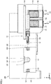
- Fig. 1 is a plan view illustrating a machine tool to which a workpiece information recognition system according to an embodiment of the present invention is applied.
- the workpiece information recognition system of the embodiment is a system that recognizes workpiece information.
- the workpiece information recognition system is applied to a machine tool 100 that processes a workpiece.
- Machine tool 100 is a combined processing machine having a turning function using a stationary tool and a milling function using a rotating tool.
- Machine tool 100 (workpiece information recognition system) includes a first spindle 121, a second spindle 122, a tool spindle 123, and a splash guard 115.
- First spindle 121, second spindle 122, and tool spindle 123 are provided in a processing area 141.
- First spindle 121 and second spindle 122 are opposite each other in a Z-axis direction extending in a horizontal direction.
- First spindle 121 is provided so as to be rotatable about a center axis 131 parallel to a Z-axis
- second spindle 122 is provided so as to be rotatable about a center axis 132 parallel to the Z-axis.
- a chuck mechanism that detachably holds the workpiece is provided in first spindle 121 and second spindle 122.
- Second spindle 122 is provided so as to be movable in the Z-axis direction.
- Tool spindle 123 holds the stationary tool during turning of a workpiece, or holds the rotating tool during milling of the workpiece, and rotates around a center axis 133.
- a clamp mechanism that detachably holds the tool is provided in tool spindle 123.
- Tool spindle 123 is provided so as to be movable in an X-axis direction extending in a vertical direction, a Y-axis direction extending in the horizontal direction and being orthogonal to the Z-axis direction, and the Z-axis direction.
- Tool spindle 123 is further provided so as to be turnable about a center axis 134 parallel to a Y-axis.
- Splash guard 115 has an appearance of machine tool 100 together with a cover body 152 (to be described later). Splash guard 115 defines processing area 141.
- Machine tool 100 (workpiece information recognition system) further includes a workpiece conveyance unit 161, cover body 152, and a workpiece placing tool 20.
- Workpiece conveyance unit 161 conveys the workpiece between processing area 141 and a workpiece storage area 151.
- Cover body 152 defines workpiece storage area 151.
- Workpiece storage area 151 is provided adjacent to processing area 141.
- Workpiece storage area 151 is provided adjacent to processing area 141 in the Z-axis direction.
- Processing area 141 and workpiece storage area 151 are separated from each other by a shutter (not illustrated) that can be opened and closed.
- Workpiece conveyance unit 161 includes a moving mechanism unit 164 and a robot arm 165.
- Robot arm 165 extends in an arm shape from moving mechanism unit 164.
- Robot arm 165 is configured to be capable of holding the workpiece.
- Robot arm 165 is configured such that the held workpiece can freely be moved in a space while an orientation of the held workpiece can freely be changed.
- Robot arm 165 is a robot arm capable of controlling six axes independently of each other.
- Moving mechanism unit 164 moves robot arm 165 between processing area 141 and workpiece storage area 151.
- Moving mechanism unit 164 linearly reciprocates robot arm 165 along the Z-axis direction.
- Moving mechanism unit 164 includes a linear guide that guides robot arm 165 in a direction parallel to the Z-axis, a servomotor that outputs rotational motion, and a rack and pinion that converts the rotational motion output from the servomotor into a linear motion to move robot arm 165 in the Z-axis direction.
- the workpiece conveyance unit in the present invention is not particularly limited as long as the workpiece can be conveyed, and may be, for example, a three-axis loader movable in three axes of the X-axis, the Y-axis, and the Z-axis.
- Fig. 2 is a perspective view illustrating the workpiece placing tool disposed in the workpiece storage area in Fig. 1 .
- Fig. 3 is a perspective view illustrating a state in which a tray is removed from the workpiece placing tool in Fig. 2 .
- machine tool 100 (workpiece information recognition system) includes workpiece placing tool 20 and a drawer 156.
- Drawer 156 is provided in a machine front surface of cover body 152. As indicated by an arrow 157 in Fig. 1 , drawer 156 is provided so as to be slidable along the Y-axis direction. Drawer 156 is provided so as to be slidable between a closed state in which drawer 156 is pushed toward workpiece storage area 151 and an open state in which drawer 156 is pulled out from workpiece storage area 151 to the front of the machine.
- Workpiece placing tool 20 is configured such that a workpiece W can be placed thereon.
- Workpiece placing tool 20 is configured such that a plurality of workpieces W can be placed thereon.
- Workpiece placing tool 20 is disposed in workpiece storage area 151.
- Workpiece placing tool 20 is placed on drawer 156.
- Workpiece placing tool 20 placed on drawer 156 is disposed in workpiece storage area 151 when drawer 156 becomes in the closed state.
- Workpiece placing tool 20 placed on drawer 156 is disposed outside workpiece storage area 151 when drawer 156 becomes in the open state.
- two sets of workpiece placing tool 20 and drawer 156 are provided side by side in the Z-axis direction.
- pre-processing workpiece W is placed on one of workpiece placing tools 20, and post-processing workpiece W is placed on the other workpiece placing tool 20.
- Figs. 2 and 3 illustrate pre-processing workpiece W having a columnar shape.
- Workpiece placing tool 20 has a tray 21 and a plate member (intermediate layer) 24.
- Tray 21 has a shallow box shape.
- Plate member 24 is stored in tray 21.
- Plate member 24 has a planar shape spreading in a flat plate shape as a whole.
- Plate member 24 is provided parallel to a Y-axis-Z-axis plane while workpiece placing tool 20 is disposed in workpiece storage area 151.
- Plate member 24 has a rectangular shape in planar view when viewed from the X-axis direction.
- Plate member 24 has a base plate 25, a spacer 26, and a top plate 27.
- Base plate 25 has a planar shape larger than top plate 27.
- Base plate 25 and top plate 27 overlap each other in a thickness direction of plate member 24.
- a plurality of openings 28 are provided in top plate 27. Opening 28 penetrates top plate 27 in the thickness direction of plate member 24. Opening 28 includes an opening surface (in the embodiment, a circular opening surface) corresponding to the shape of workpiece W.
- the plurality of openings 28 are provided in a lattice shape along the Y-axis direction and the Z-axis direction while workpiece placing tool 20 is disposed in workpiece storage area 151.
- Spacer 26 has a frame shape extending in a band shape along a periphery of top plate 27. Spacer 26 is interposed between base plate 25 and top plate 27 in the thickness direction of plate member 24. Consequently, a gap is provided between base plate 25 and top plate 27 immediately below opening 28. Workpiece W is inserted into opening 28 and placed on base plate 25, whereby workpiece W is held by plate member 24.
- Machine tool 100 (workpiece information recognition system) further includes a reference block 31 as a reference object.
- Reference block 31 is provided so as to be detachable on workpiece placing tool 20.
- a plurality of reference blocks 31 are provided in workpiece placing tool 20.
- At least three reference blocks 31 are provided in workpiece placing tool 20.
- a reference block 31A, a reference block 31B, and a reference block 31C are provided in workpiece placing tool 20.
- Reference block 31 is provided on plate member 24 of workpiece placing tool 20.
- Reference block 31 is provided on base plate 25 of plate member 24.
- Reference block 31 is fastened to workpiece placing tool 20 by bolts.
- Reference block 31 can be removed from workpiece placing tool 20 by removing the bolts.
- the plurality of reference blocks 31 are disposed apart from one another.
- the plurality of reference blocks 31 are disposed apart from one another in a plane where plate member 24 spreads.
- the plurality of reference blocks 31 are provided on the periphery of base plate 25 exposed from top plate 27.
- the plurality of reference blocks 31 are provided in a region outside a region where the plurality of openings 28 are provided (that is, a region where the plurality of workpieces W are held).
- Reference block 31A, reference block 31B, and reference block 31C are provided apart from one another in a longitudinal direction of a rectangular shape of plate member 24 in planar view.
- Reference block 31B and reference block 31C are provided apart from each other in a short direction of the rectangular shape of plate member 24 in planar view.
- Reference block 31A is provided at a center position between reference block 31B and reference block 31C in the short direction of the rectangular shape of plate member 24 in planar view.
- Reference block 31A, reference block 31B, and reference block 31C are located at three corners of an isosceles triangle.
- a method for detachably providing reference block 31 in workpiece placing tool 20 is not limited to a method in which the bolts are used, and may be, for example, a method in which a clip or fitting is used.
- the positions where reference block 31A, reference block 31B, and reference block 31C are provided are not particularly limited. However, according to the configuration described above, reference block 31A, reference block 31B, and reference block 31C can be disposed far apart from one another in the plane where plate member 24 spreads.
- Reference block 31 is a solid. Reference block 31 has a convex shape protruding from base plate 25. In the embodiment, reference block 31 is formed by a square pole block. In a state in which workpiece placing tool 20 is disposed in workpiece storage area 151, reference block 31 has a square pole shape in which a verticality extending in the Y-axis direction and a width extending in the Z-axis direction are equal to each other and a height extending in the X-axis direction is greater than each of the verticality and the width.
- Reference block 31 is not limited to the above-described square pole, and may have, for example, a square pole shape having the verticality and the width different from each other.
- Reference block 31 has the square pole shape in which the height extending in the X-axis direction is equal to each of the verticality and the width, or a square pole shape in which the height extending in the X-axis direction is smaller than each of the verticality and the width.
- Reference block 31 may have a columnar shape or a triangular shape.
- Fig. 4 is a perspective view illustrating a leading end of the robot arm in Fig. 1 .
- robot arm 165 includes a movable unit 171 and a workpiece holder 172 (172P, 172Q).
- Movable unit 171 is provided at a leading end of robot arm 165 extending in an arm shape from moving mechanism unit 164. Movable unit 171 is provided so as to be swingable about a turning axis 181 in Fig. 4 , and provided so as to be rotatable about a rotation axis 182 in Fig. 4 .
- Workpiece holder 172 is provided in movable unit 171. Workpiece holder 172 is configured to detachably hold the workpiece. Workpiece holder 172P and workpiece holder 172Q are provided as workpiece holder 172 in order to simultaneously hold two workpieces.
- Machine tool 100 further includes an information detector 41.
- Information detector 41 is configured to detect information about reference block 31.
- the information about reference block 31 may include information about a size, a shape, or a position of reference block 31.
- Information detector 41 is formed by a laser sensor.
- Information detector 41 includes an emission unit (not illustrated) that emits laser light and a light receiving unit (not illustrated) that receives the laser light emitted from the emission unit and reflected by the object.
- Information detector 41 can detect positional information about the object based on a light receiving position of the laser light in the light receiving unit and time until the laser light returns from the emission unit to the light receiving unit.
- Information detector 41 is fixed to workpiece conveyance unit 161.
- Information detector 41 is fixed to robot arm 165.
- Information detector 41 is fixed to movable unit 171 of robot arm 165.
- Information detector 41 is provided adjacent to workpiece holder 172. With this configuration, information detector 41 can freely be moved in the space while the orientation of information detector 41 can freely be changed with the operation of workpiece conveyance unit 161.
- Information detector in the present invention is not particularly limited as long as information detector can detect various types of information about the reference object, and may be, for example, a contact type stylus.
- information detector 41 is fixed to workpiece conveyance unit 161.
- the present invention is not limited to this.
- a dedicated actuator that moves information detector 41 may be provided.
- Fig. 5 is a block diagram illustrating a configuration for recognizing the information about the workpiece placed on the workpiece placing tool.
- machine tool 100 (workpiece information recognition system) further includes a control device 51.
- Control device 51 includes a control panel provided on machine tool 100.
- Control device 51 receives the information about reference block 31 from information detector 41.
- Control device 51 includes a storage 53 and a controller 52.
- Storage 53 stores data on a relationship between the information about reference block 31 and the information about the workpiece.
- the information about the workpiece may include information about the size, the processing state, the processing method, or the disposition of the workpiece.
- Controller 52 recognizes the information about the workpiece placed on workpiece placing tool 20 by checking the information about reference block 31 detected by information detector 41 with the data stored in storage 53.
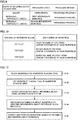
- Fig. 6 is a table illustrating an example of the data stored in the storage in Fig. 5 .
- Fig. 7 is a plan view illustrating an example of the workpiece placing tool on which different types of workpieces are placed.
- Fig. 8 is a plan view illustrating another example of the workpiece placing tool on which different types of workpieces are placed.
- storage 53 may store correspondence between the size of reference block 31 (the vertical and width lengths of the square-pole shaped reference block 31 in planar view) and the size of workpiece W (a diameter and the height of columnar-shaped workpiece W).
- storage 53 may store vertical and width lengths L1 of reference block 31 and a diameter D1 and a height H1 of workpiece W while associating vertical and width lengths L1 of reference block 31 with diameter D1 and height H1 of workpiece W, store vertical and width lengths L2 of reference block 31 and a diameter D2 and a height H2 of workpiece W while associating vertical and width lengths L2 of reference block 31 with diameter D2 and height H2 of workpiece W, and store vertical and width lengths L3 of reference block 31 and a diameter D3 and a height H3 of workpiece W while associating vertical and width lengths L3 of reference block 31 with diameter D3 and height H3 of workpiece W.
- reference block 31A, reference block 31B, and reference block 31C may have the size indicating the information about workpiece W.
- reference block 31A may have the size indicating the information about workpiece W, and reference block 31B and reference block 31C may be used only to detect an inclination of plate member 24 (to be described later).
- Fig. 9 is a table illustrating another example of the data stored in the storage in Fig. 5 .
- Fig. 10 is a table illustrating still another example of the data stored in the storage in Fig. 5 .
- storage 53 may store the correspondence between the shape of reference block 31 (the shape of reference block 31 in planar view), the processing state of workpiece W, and the processing method of workpiece W. More specifically, storage 53 may store the square shape of reference block 31 and the fact that the processing state of workpiece W is unprocessed and the method for processing workpiece W is the processing using a processing program H while associating the square shape of reference block 31 with the fact that the processing state of workpiece W is unprocessed and the method for processing workpiece W is the processing using processing program H, store the shape of the rectangle (verticality > width) of reference block 31 and the fact that the processing state of workpiece W is a first intermediate workpiece and the method for processing workpiece W is the processing using a processing program I while associating the shape of the rectangle (verticality > width) of reference block 31 and the fact that the processing state of workpiece W is the first intermediate workpiece and the method for processing workpiece W is the processing using processing program I, and store the shape of the rectangle (vert
- storage 53 may store the correspondence between the position of reference block 31 (a coordinate of the center of reference block 31 in planar view) and the disposition of workpiece W (a mode in which a plurality of workpieces W are placed on workpiece placing tool 20 and a center coordinate of each workpiece W in planar view).
- storage 53 may store the center coordinate (X1, Y1, Z1) of reference block 31 and the mode in which the plurality of workpieces W are arranged in four columns in the Z-axis direction and in five rows in the Y-axis direction and the center coordinate of each workpiece W while associating the center coordinate (X1, Y1, Z1) of reference block 31 with the mode in which the plurality of workpieces W are arranged in four columns in the Z-axis direction and in five rows in the Y-axis direction and the center coordinate of each workpiece W, store the center coordinate (X2, Y2, Z2) of reference block 31 and the mode in which the plurality of workpieces W are arranged in six columns in the Z-axis direction and in six rows in the Y-axis direction and the center coordinate of each workpiece W while associating the center coordinate (X2, Y2, Z2) of reference block 31 with the mode in which the plurality of workpieces W are arranged in six columns in the Z-axis direction and in six rows in the Y-axis direction and
- the data stored in storage 53 described above is an example, and a combination of a content of the information about reference block 31, a content of the information about the workpiece, and the information about reference block 31 and the information about the workpiece associated with each other is not particularly limited.
- Fig. 11 is a flowchart illustrating steps of recognizing the information about the workpiece placed on the workpiece placing tool.
- Figs. 12 to 14 are plan views each illustrating a method for scanning the reference block with the laser light in steps of recognizing the information about the workpiece in Fig. 11 .
- the plurality of workpieces W are placed on workpiece placing tool 20 (S101). In this step, the plurality of workpieces W are inserted into the plurality of openings 28, respectively.
- workpiece placing tool 20 is set in workpiece storage area 151 (SI02). In this step, workpiece placing tool 20 is placed on drawer 156 in the open state. By putting drawer 156 in the closed state, workpiece placing tool 20 is disposed in workpiece storage area 151.
- information detector 41 detects the information about reference block 31 (31A, 31B, 31C) (S103).
- information detector 41 is positioned above reference block 31 by operating workpiece conveyance unit 161 (moving mechanism unit 164, robot arm 165). Workpiece conveyance unit 161 is operated while the laser light is emitted downward from information detector 41, thereby performing scanning with the laser light in each of the Z-axis direction and the Y-axis direction. Along with the scanning of the laser light, information detector 41 receives the reflected light of the laser light. At this point, a difference in the time the laser light returns to information detector 41 is generated between the position where reference block 31 exists and the position where reference block 31 does not exist.
- reference block 31 (the vertical and width lengths of reference block 31 in planar view) and the shape of reference block 31 (the shape of reference block 31 in planar view) are detected based on the operation position of workpiece conveyance unit 161 at timing of generating the difference in the return time of the laser light.
- the position of reference block 31 (the center coordinate of reference block 31 in planar view) is detected by considering both the return time of the laser light and the operation position of workpiece conveyance unit 161.
- the scanning of the laser light is performed on each of reference block 31A, reference block 31B, and reference block 31C. Consequently, the center coordinate (Xa, Ya, Za) of reference block 31A in planar view, the center coordinate (Xb, Yb, Zb) of reference block 31B in planar view, and the center coordinate (Xc, Yc, Zc) of reference block 31C in planar view are detected.
- information detector 41 is provided in workpiece conveyance unit 161 that conveys the workpiece, so that information detector 41 can be moved toward reference block 31 without adding a new actuator. Furthermore, accessibility of information detector 41 to reference block 31 can be improved.
- controller 52 recognizes the information about workpiece W by checking the information about reference block 31 with the data stored in storage 53 (S104).
- controller 52 recognizes the information about the size of workpiece W ( Fig. 6 ), the processing state and processing method of workpiece W ( Fig. 9 ), and the disposition of workpiece W ( Fig. 10 ) by checking the information about reference block 31 detected in step S103 with the data stored in storage 53.
- Controller 52 further detects the inclination of plate member 24 in workpiece placing tool 20 from the center coordinates of reference block 31A, reference block 31B, and reference block 31C. Controller 52 corrects the position of each workpiece W placed on workpiece placing tool 20 based on the detected inclination of plate member 24.
- controller 52 performs the conveyance and processing of the workpiece based on the obtained information about workpiece (S105).
- Controller 52 grasps how the plurality of workpiece W exist in a spatial positions of workpiece storage area 151 using the information about the size of workpiece W and the disposition of workpiece W recognized in the previous step. For this reason, controller 52 can operate workpiece conveyance unit 161 such that workpiece W is accurately positioned at the position and orientation in which workpiece holder 172 of robot arm 165 can hold workpiece W. At this point, a positional deviation of workpiece W due to the inclination of plate member 24 is corrected in the previous step, so that workpiece holder 172 can more accurately positioned with respect to each workpiece W placed on workpiece placing tool 20.
- information detector 41 may perform a step of emitting the laser light toward workpiece W to receive the reflected light. Holding failure of workpiece W by workpiece holder 172 can be prevented by determining that workpiece W does not exist during the abnormal light receiving state of the reflected light.
- controller 52 After workpiece conveyance unit 161 moves workpiece W from workpiece storage area 151 to processing area 141, controller 52 processes workpiece W based on the information about the processing state and the processing method of workpiece W recognized in the previous step.
- the workpiece information recognition system of the embodiment includes workpiece placing tool 20 capable of placing the workpiece, reference block 31 as a reference object detachably provided on workpiece placing tool 20, information detector 41 that detects the information about reference block 31, and control device 51 that receives the information about reference block 31 from information detector 41.
- Control device 51 includes storage 53 that stores the data on the relationship between the information about reference block 31 and the information about the workpiece and controller 52 that recognizes the information about the workpiece placed on workpiece placing tool 20 by checking the information about reference block 31 detected by information detector 41 with the data stored in storage 53.
- reference block 31 is detachably provided on workpiece placing tool 20
- reference block 31 provided on reference block 31 may be replaced with reference block 31 corresponding to the workpiece. For this reason, it is possible to easily cope with the change in the type of the workpiece.
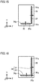
- Figs. 15 and 16 are plan views illustrating various modifications of the reference block in Fig. 12 .
- a reference block 36 and a reference block 37 are provided on workpiece placing tool 20 instead of reference block 31 in Fig. 12 .
- Reference block 36 has an elongated shape extending along the Z-axis direction. Reference block 36 is provided along an end side of workpiece placing tool 20 (plate member 24) extending in the Z-axis direction.
- Reference block 37 has an elongated shape extending along the Y-axis direction. Reference block 37 is provided along an end side of workpiece placing tool 20 (plate member 24) extending along the Z-axis direction.
- step S103 in Fig. 11 workpiece conveyance unit 161 is operated while information detector 41 emits the laser light toward reference block 36, thereby performing the scanning with the laser light along each of the longitudinal direction (Z-axis direction) and the short direction (Y-axis direction) of reference block 36. Consequently, the coordinates of one end 36p and the other end 36q in the longitudinal direction of reference block 36 are detected.
- Workpiece conveyance unit 161 is operated while information detector 41 emits the laser light toward reference block 37, thereby performing the scanning with the laser light along each of the longitudinal direction (Y-axis direction) and the short direction (Z-axis direction) of reference block 37. Consequently, the coordinates of one end 37p and the other end 37q in the longitudinal direction of reference block 37 are detected.
- controller 52 detects the inclination of plate member 24 in workpiece placing tool 20 from the coordinates of one end 36p and the other end 36q of reference block 36 and the coordinates of one end 37p and the other end 37q of reference block 37.
- a reference block 38 is provided on workpiece placing tool 20 instead of reference block 31 in Fig. 12 .
- Reference block 38 has a shape in which reference block 36 and reference block 37 in Fig. 15 are connected to each other at a corner of workpiece placing tool 20 (plate member 24).
- the inclination of plate member 24 in workpiece placing tool 20 is detected by scanning reference block 36 and reference block 37 with the laser light along the Y-axis direction and the Z-axis direction.
- three reference blocks are not necessarily required, but two reference blocks 36, 37 or one reference block 38 may be used.
- the inclination of plate member 24 may be detected using at least four reference blocks.
- the reference block is provided on plate member 24 of workpiece placing tool 20.
- the reference block may be provided on tray 21 of workpiece placing tool 20.
- the reference object in the present invention is not limited to the above solid reference block.
- the reference object may be a sheet-shaped mirror.
- the solid reference block is used as the reference object, durability of the reference object can be improved.
- the sheet-shaped mirror is used as the reference object, a freedom degree of the installation location of the reference object can be increased.
- the workpiece information recognition system of the present invention is not limited to the machine tool, but may be applied to various workpiece processing devices such as a workpiece measuring device and a workpiece cleaning device.
- a workpiece information recognition system includes a workpiece placing tool capable of placing a workpiece, a reference object detachably provided on the workpiece placing tool, an information detector configured to detect information about the reference object, and a control device configured to receive the information about the reference object from the information detector.
- the control device includes a storage configured to store data on a relationship between the information about the reference object and information about the workpiece and a controller configured to recognize the information about the workpiece placed on the workpiece placing tool by checking the information about the reference object detected by the information detector with the data stored in the storage.
- the reference object provided on the workpiece placing tool may be replaced with the reference object corresponding to the workpiece. For this reason, it is possible to easily cope with the change in the type of the workpiece.
- the information about the reference object includes the information about the size, the shape, or the position of the reference object.
- the information about the workpiece placed on the workpiece placing tool can be recognized through various pieces of information about the reference obj ect.
- the information about the workpiece includes the information about the size, the processing state, the processing method, or the disposition of the workpiece.
- the workpiece placing tool includes the plate member in which the plurality of openings into which the workpieces are inserted are provided. At least three reference objects disposed apart from one another are provided in the plate member.
- the inclination of the plate member can be recognized through the positions of the three reference objects.
- the reference object is a solid.
- the durability of the reference object can be improved.
- the workpiece information recognition system further includes the workpiece conveyance unit that conveys the workpiece placed on the workpiece placing tool.
- the information detector is fixed to the workpiece conveyance unit.
- the information detector can be moved toward the reference object using the workpiece conveyance unit that conveys the workpiece.
- the present invention is applied to the machine tool.
Landscapes
- Engineering & Computer Science (AREA)
- Mechanical Engineering (AREA)
- Robotics (AREA)
- Physics & Mathematics (AREA)
- Optics & Photonics (AREA)
- Automation & Control Theory (AREA)
- Manipulator (AREA)
- Machine Tool Sensing Apparatuses (AREA)
- Feeding Of Workpieces (AREA)
- Turning (AREA)
- Numerical Control (AREA)
Abstract
Description
- The present invention relates to a workpiece information recognition system.
- In relation to a conventional workpiece information recognition system, for example, Japanese Utility Model Laying-Open No.
2-52399 - The board management device disclosed in PTL 1 includes a tray that accommodates the board and is individualized with an identification mark, recognition means for determining the tray from the identification mark, and data processing means for storing the data on the board accommodated in the tray together with the tray recognition data obtained by the recognition display and for enabling any data on the accommodated substrate to be extracted from the stored identification data on the tray. As an identification mark attached to the tray, an identification hole is provided in the tray, or a barcode is printed.
- PTL 1: Japanese Utility Model Laying-Open No.
2-52399 - As disclosed in PTL 1, a technique of providing the identification mark such as the identification hole or the barcode on the tray that accommodate the board is known in order to recognize the information about the board. It is conceivable to apply the technique to an information recognition system for the workpiece placed on a workpiece placing tool. However, in this case, every time a type of the workpiece is changed, it is necessary to prepare the workpiece placing tool including the identification mark corresponding to the workpiece. As a result, the number of workpiece placing tools increases, or preparation work in advance becomes complicated, and it is not possible to easily cope with a change in the type of the workpiece.
- An object of the present invention is to solve the above-described problem, and to provide a workpiece information recognition system capable of easily coping with the change in the type of the workpiece.
- According to the present invention, a workpiece information recognition system includes a workpiece placing tool capable of placing a workpiece, a reference object detachably provided on the workpiece placing tool, an information detector configured to detect information about the reference object, and a control device configured to receive the information about the reference object from the information detector. The control device includes a storage configured to store data on a relationship between the information about the reference object and information about the workpiece and a controller configured to recognize the information about the workpiece placed on the workpiece placing tool by checking the information about the reference object detected by the information detector with the data stored in the storage.
- According to the present invention, the workpiece information recognition system capable of easily coping with the change in the type of the workpiece can be provided.
-
-
Fig. 1 is a plan view illustrating a machine tool to which a workpiece information recognition system according to an embodiment of the present invention is applied. -
Fig. 2 is a perspective view illustrating a workpiece placing tool disposed in a workpiece storage area inFig. 1 . -
Fig. 3 is a perspective view illustrating a state in which a tray is removed from the workpiece placing tool inFig. 2 . -
Fig. 4 is a perspective view illustrating a leading end of a robot arm inFig. 1 . -
Fig. 5 is a block diagram illustrating a configuration for recognizing information about a workpiece placed on the workpiece placing tool. -
Fig. 6 is a table illustrating an example of data stored in a storage inFig. 5 . -
Fig. 7 is a plan view illustrating an example of the workpiece placing tool on which different types of workpieces are placed. -
Fig. 8 is a plan view illustrating another example of the workpiece placing tool on which different types of workpieces are placed. -
Fig. 9 is a table illustrating another example of the data stored in the storage inFig. 5 . -
Fig. 10 is a table illustrating still another example of the data stored in the storage inFig. 5 . -
Fig. 11 is a flowchart illustrating steps of recognizing the information about the workpiece placed on the workpiece placing tool. -
Fig. 12 is a plan view illustrating a method of scanning a reference block with laser light in the steps of recognizing the information about the workpiece inFig. 11 . -
Fig. 13 is a plan view illustrating the method of scanning the reference block with the laser light in the steps of recognizing the information about the workpiece inFig. 11 . -
Fig. 14 is a plan view illustrating the method of scanning the reference block with the laser light in the steps of recognizing the information about the workpiece inFig. 11 . -
Fig. 15 is a plan view illustrating various modifications of the reference block illustrated inFig. 12 . -
Fig. 16 is a plan view illustrating various modifications of the reference block inFig. 12 . - An embodiment of the present invention will be described with reference to the drawings. In the drawings referred to below, the same or corresponding member is denoted by the same reference numeral.
-
Fig. 1 is a plan view illustrating a machine tool to which a workpiece information recognition system according to an embodiment of the present invention is applied. - Referring to
Fig. 1 , the workpiece information recognition system of the embodiment is a system that recognizes workpiece information. In the embodiment, as an example, the workpiece information recognition system is applied to amachine tool 100 that processes a workpiece.Machine tool 100 is a combined processing machine having a turning function using a stationary tool and a milling function using a rotating tool. - A basic configuration of
machine tool 100 will first be described. Machine tool 100 (workpiece information recognition system) includes afirst spindle 121, asecond spindle 122, atool spindle 123, and asplash guard 115.First spindle 121,second spindle 122, andtool spindle 123 are provided in aprocessing area 141. -
First spindle 121 andsecond spindle 122 are opposite each other in a Z-axis direction extending in a horizontal direction.First spindle 121 is provided so as to be rotatable about acenter axis 131 parallel to a Z-axis, andsecond spindle 122 is provided so as to be rotatable about acenter axis 132 parallel to the Z-axis. A chuck mechanism that detachably holds the workpiece is provided infirst spindle 121 andsecond spindle 122.Second spindle 122 is provided so as to be movable in the Z-axis direction. -
Tool spindle 123 holds the stationary tool during turning of a workpiece, or holds the rotating tool during milling of the workpiece, and rotates around acenter axis 133. A clamp mechanism that detachably holds the tool is provided intool spindle 123.Tool spindle 123 is provided so as to be movable in an X-axis direction extending in a vertical direction, a Y-axis direction extending in the horizontal direction and being orthogonal to the Z-axis direction, and the Z-axis direction.Tool spindle 123 is further provided so as to be turnable about acenter axis 134 parallel to a Y-axis. - Splash
guard 115 has an appearance ofmachine tool 100 together with a cover body 152 (to be described later). Splashguard 115 definesprocessing area 141. - Machine tool 100 (workpiece information recognition system) further includes a
workpiece conveyance unit 161,cover body 152, and a workpiece placingtool 20.Workpiece conveyance unit 161 conveys the workpiece betweenprocessing area 141 and aworkpiece storage area 151. -
Cover body 152 definesworkpiece storage area 151.Workpiece storage area 151 is provided adjacent toprocessing area 141.Workpiece storage area 151 is provided adjacent toprocessing area 141 in the Z-axis direction.Processing area 141 andworkpiece storage area 151 are separated from each other by a shutter (not illustrated) that can be opened and closed. -
Workpiece conveyance unit 161 includes amoving mechanism unit 164 and arobot arm 165.Robot arm 165 extends in an arm shape frommoving mechanism unit 164.Robot arm 165 is configured to be capable of holding the workpiece.Robot arm 165 is configured such that the held workpiece can freely be moved in a space while an orientation of the held workpiece can freely be changed.Robot arm 165 is a robot arm capable of controlling six axes independently of each other. - Moving
mechanism unit 164 movesrobot arm 165 betweenprocessing area 141 andworkpiece storage area 151. Movingmechanism unit 164 linearly reciprocatesrobot arm 165 along the Z-axis direction. Movingmechanism unit 164 includes a linear guide that guidesrobot arm 165 in a direction parallel to the Z-axis, a servomotor that outputs rotational motion, and a rack and pinion that converts the rotational motion output from the servomotor into a linear motion to moverobot arm 165 in the Z-axis direction. - The workpiece conveyance unit in the present invention is not particularly limited as long as the workpiece can be conveyed, and may be, for example, a three-axis loader movable in three axes of the X-axis, the Y-axis, and the Z-axis.
-
Fig. 2 is a perspective view illustrating the workpiece placing tool disposed in the workpiece storage area inFig. 1 .Fig. 3 is a perspective view illustrating a state in which a tray is removed from the workpiece placing tool inFig. 2 . - Referring to
Figs. 1 to 3 , machine tool 100 (workpiece information recognition system) includesworkpiece placing tool 20 and adrawer 156. -
Drawer 156 is provided in a machine front surface ofcover body 152. As indicated by anarrow 157 inFig. 1 ,drawer 156 is provided so as to be slidable along the Y-axis direction.Drawer 156 is provided so as to be slidable between a closed state in whichdrawer 156 is pushed towardworkpiece storage area 151 and an open state in whichdrawer 156 is pulled out fromworkpiece storage area 151 to the front of the machine. -
Workpiece placing tool 20 is configured such that a workpiece W can be placed thereon.Workpiece placing tool 20 is configured such that a plurality of workpieces W can be placed thereon.Workpiece placing tool 20 is disposed inworkpiece storage area 151.Workpiece placing tool 20 is placed ondrawer 156.Workpiece placing tool 20 placed ondrawer 156 is disposed inworkpiece storage area 151 whendrawer 156 becomes in the closed state.Workpiece placing tool 20 placed ondrawer 156 is disposed outsideworkpiece storage area 151 whendrawer 156 becomes in the open state. - In the embodiment, two sets of
workpiece placing tool 20 anddrawer 156 are provided side by side in the Z-axis direction. As a typical example, pre-processing workpiece W is placed on one ofworkpiece placing tools 20, and post-processing workpiece W is placed on the otherworkpiece placing tool 20.Figs. 2 and3 illustrate pre-processing workpiece W having a columnar shape. -
Workpiece placing tool 20 has atray 21 and a plate member (intermediate layer) 24.Tray 21 has a shallow box shape.Plate member 24 is stored intray 21.Plate member 24 has a planar shape spreading in a flat plate shape as a whole.Plate member 24 is provided parallel to a Y-axis-Z-axis plane whileworkpiece placing tool 20 is disposed inworkpiece storage area 151.Plate member 24 has a rectangular shape in planar view when viewed from the X-axis direction. -
Plate member 24 has abase plate 25, aspacer 26, and atop plate 27.Base plate 25 has a planar shape larger thantop plate 27.Base plate 25 andtop plate 27 overlap each other in a thickness direction ofplate member 24. A plurality ofopenings 28 are provided intop plate 27.Opening 28 penetratestop plate 27 in the thickness direction ofplate member 24.Opening 28 includes an opening surface (in the embodiment, a circular opening surface) corresponding to the shape of workpiece W. The plurality ofopenings 28 are provided in a lattice shape along the Y-axis direction and the Z-axis direction whileworkpiece placing tool 20 is disposed inworkpiece storage area 151. -
Spacer 26 has a frame shape extending in a band shape along a periphery oftop plate 27.Spacer 26 is interposed betweenbase plate 25 andtop plate 27 in the thickness direction ofplate member 24. Consequently, a gap is provided betweenbase plate 25 andtop plate 27 immediately below opening 28. Workpiece W is inserted intoopening 28 and placed onbase plate 25, whereby workpiece W is held byplate member 24. - A configuration for recognizing various information about workpiece W placed on
workpiece placing tool 20 inworkpiece storage area 151 will be described below. - Machine tool 100 (workpiece information recognition system) further includes a
reference block 31 as a reference object. -
Reference block 31 is provided so as to be detachable onworkpiece placing tool 20. A plurality of reference blocks 31 are provided inworkpiece placing tool 20. At least threereference blocks 31 are provided inworkpiece placing tool 20. Areference block 31A, areference block 31B, and areference block 31C are provided inworkpiece placing tool 20. -
Reference block 31 is provided onplate member 24 ofworkpiece placing tool 20.Reference block 31 is provided onbase plate 25 ofplate member 24.Reference block 31 is fastened to workpiece placingtool 20 by bolts.Reference block 31 can be removed fromworkpiece placing tool 20 by removing the bolts. - The plurality of reference blocks 31 (31A, 31B, 31C) are disposed apart from one another. The plurality of reference blocks 31 are disposed apart from one another in a plane where
plate member 24 spreads. The plurality of reference blocks 31 are provided on the periphery ofbase plate 25 exposed fromtop plate 27. The plurality of reference blocks 31 are provided in a region outside a region where the plurality ofopenings 28 are provided (that is, a region where the plurality of workpieces W are held). -
Reference block 31A,reference block 31B, andreference block 31C are provided apart from one another in a longitudinal direction of a rectangular shape ofplate member 24 in planar view.Reference block 31B andreference block 31C are provided apart from each other in a short direction of the rectangular shape ofplate member 24 in planar view.Reference block 31A is provided at a center position betweenreference block 31B andreference block 31C in the short direction of the rectangular shape ofplate member 24 in planar view.Reference block 31A,reference block 31B, andreference block 31C are located at three corners of an isosceles triangle. - A method for detachably providing
reference block 31 inworkpiece placing tool 20 is not limited to a method in which the bolts are used, and may be, for example, a method in which a clip or fitting is used. The positions wherereference block 31A,reference block 31B, andreference block 31C are provided are not particularly limited. However, according to the configuration described above,reference block 31A,reference block 31B, andreference block 31C can be disposed far apart from one another in the plane whereplate member 24 spreads. -
Reference block 31 is a solid.Reference block 31 has a convex shape protruding frombase plate 25. In the embodiment,reference block 31 is formed by a square pole block. In a state in whichworkpiece placing tool 20 is disposed inworkpiece storage area 151,reference block 31 has a square pole shape in which a verticality extending in the Y-axis direction and a width extending in the Z-axis direction are equal to each other and a height extending in the X-axis direction is greater than each of the verticality and the width. -
Reference block 31 is not limited to the above-described square pole, and may have, for example, a square pole shape having the verticality and the width different from each other.Reference block 31 has the square pole shape in which the height extending in the X-axis direction is equal to each of the verticality and the width, or a square pole shape in which the height extending in the X-axis direction is smaller than each of the verticality and the width.Reference block 31 may have a columnar shape or a triangular shape. -
Fig. 4 is a perspective view illustrating a leading end of the robot arm inFig. 1 . Referring toFigs. 1 and4 ,robot arm 165 includes amovable unit 171 and a workpiece holder 172 (172P, 172Q). -
Movable unit 171 is provided at a leading end ofrobot arm 165 extending in an arm shape from movingmechanism unit 164.Movable unit 171 is provided so as to be swingable about a turningaxis 181 inFig. 4 , and provided so as to be rotatable about arotation axis 182 inFig. 4 . -
Workpiece holder 172 is provided inmovable unit 171.Workpiece holder 172 is configured to detachably hold the workpiece.Workpiece holder 172P andworkpiece holder 172Q are provided asworkpiece holder 172 in order to simultaneously hold two workpieces. - Machine tool 100 (workpiece information recognition system) further includes an
information detector 41.Information detector 41 is configured to detect information aboutreference block 31. The information aboutreference block 31 may include information about a size, a shape, or a position ofreference block 31. -
Information detector 41 is formed by a laser sensor.Information detector 41 includes an emission unit (not illustrated) that emits laser light and a light receiving unit (not illustrated) that receives the laser light emitted from the emission unit and reflected by the object.Information detector 41 can detect positional information about the object based on a light receiving position of the laser light in the light receiving unit and time until the laser light returns from the emission unit to the light receiving unit. -
Information detector 41 is fixed toworkpiece conveyance unit 161.Information detector 41 is fixed torobot arm 165.Information detector 41 is fixed tomovable unit 171 ofrobot arm 165.Information detector 41 is provided adjacent toworkpiece holder 172. With this configuration,information detector 41 can freely be moved in the space while the orientation ofinformation detector 41 can freely be changed with the operation ofworkpiece conveyance unit 161. - Information detector in the present invention is not particularly limited as long as information detector can detect various types of information about the reference object, and may be, for example, a contact type stylus. In the embodiment,
information detector 41 is fixed toworkpiece conveyance unit 161. However, the present invention is not limited to this. For example, a dedicated actuator that movesinformation detector 41 may be provided. -
Fig. 5 is a block diagram illustrating a configuration for recognizing the information about the workpiece placed on the workpiece placing tool. - Referring to
Figs. 1 and5 , machine tool 100 (workpiece information recognition system) further includes acontrol device 51.Control device 51 includes a control panel provided onmachine tool 100.Control device 51 receives the information aboutreference block 31 frominformation detector 41.Control device 51 includes astorage 53 and acontroller 52. -
Storage 53 stores data on a relationship between the information aboutreference block 31 and the information about the workpiece. The information about the workpiece may include information about the size, the processing state, the processing method, or the disposition of the workpiece. -
Controller 52 recognizes the information about the workpiece placed onworkpiece placing tool 20 by checking the information aboutreference block 31 detected byinformation detector 41 with the data stored instorage 53. -
Fig. 6 is a table illustrating an example of the data stored in the storage inFig. 5 .Fig. 7 is a plan view illustrating an example of the workpiece placing tool on which different types of workpieces are placed.Fig. 8 is a plan view illustrating another example of the workpiece placing tool on which different types of workpieces are placed. - Referring to
Figs. 6 to 8 ,storage 53 may store correspondence between the size of reference block 31 (the vertical and width lengths of the square-pole shapedreference block 31 in planar view) and the size of workpiece W (a diameter and the height of columnar-shaped workpiece W). More specifically,storage 53 may store vertical and width lengths L1 ofreference block 31 and a diameter D1 and a height H1 of workpiece W while associating vertical and width lengths L1 ofreference block 31 with diameter D1 and height H1 of workpiece W, store vertical and width lengths L2 ofreference block 31 and a diameter D2 and a height H2 of workpiece W while associating vertical and width lengths L2 ofreference block 31 with diameter D2 and height H2 of workpiece W, and store vertical and width lengths L3 ofreference block 31 and a diameter D3 and a height H3 of workpiece W while associating vertical and width lengths L3 ofreference block 31 with diameter D3 and height H3 of workpiece W. - At this point, as illustrated in
Fig. 7 , all ofreference block 31A,reference block 31B, andreference block 31C may have the size indicating the information about workpiece W. As illustrated inFig. 8 ,reference block 31A may have the size indicating the information about workpiece W, andreference block 31B andreference block 31C may be used only to detect an inclination of plate member 24 (to be described later). -
Fig. 9 is a table illustrating another example of the data stored in the storage inFig. 5 .Fig. 10 is a table illustrating still another example of the data stored in the storage inFig. 5 . - Referring to
Fig. 9 , storage 53 may store the correspondence between the shape of reference block 31 (the shape of reference block 31 in planar view), the processing state of workpiece W, and the processing method of workpiece W. More specifically, storage 53 may store the square shape of reference block 31 and the fact that the processing state of workpiece W is unprocessed and the method for processing workpiece W is the processing using a processing program H while associating the square shape of reference block 31 with the fact that the processing state of workpiece W is unprocessed and the method for processing workpiece W is the processing using processing program H, store the shape of the rectangle (verticality > width) of reference block 31 and the fact that the processing state of workpiece W is a first intermediate workpiece and the method for processing workpiece W is the processing using a processing program I while associating the shape of the rectangle (verticality > width) of reference block 31 and the fact that the processing state of workpiece W is the first intermediate workpiece and the method for processing workpiece W is the processing using processing program I, and store the shape of the rectangle (verticality < width) of reference block 31 and the fact that the processing state of workpiece W is a second intermediate workpiece and the method for processing workpiece W is the processing using a processing program J while associating the shape of the rectangle (verticality < width) of reference block 31 with the fact that the processing state of workpiece W is the second intermediate workpiece and the method for processing workpiece W is the processing using processing program J. - Referring to
Fig. 10 ,storage 53 may store the correspondence between the position of reference block 31 (a coordinate of the center ofreference block 31 in planar view) and the disposition of workpiece W (a mode in which a plurality of workpieces W are placed onworkpiece placing tool 20 and a center coordinate of each workpiece W in planar view). More specifically, storage 53 may store the center coordinate (X1, Y1, Z1) of reference block 31 and the mode in which the plurality of workpieces W are arranged in four columns in the Z-axis direction and in five rows in the Y-axis direction and the center coordinate of each workpiece W while associating the center coordinate (X1, Y1, Z1) of reference block 31 with the mode in which the plurality of workpieces W are arranged in four columns in the Z-axis direction and in five rows in the Y-axis direction and the center coordinate of each workpiece W, store the center coordinate (X2, Y2, Z2) of reference block 31 and the mode in which the plurality of workpieces W are arranged in six columns in the Z-axis direction and in six rows in the Y-axis direction and the center coordinate of each workpiece W while associating the center coordinate (X2, Y2, Z2) of reference block 31 with the mode in which the plurality of workpieces W are arranged in six columns in the Z-axis direction and in six rows in the Y-axis direction and the center coordinate of each workpiece W, and store the center coordinate (X3, Y3, Z3) of reference block 31 and the mode in which the plurality of workpieces W are arranged in seven columns in the Z-axis direction and in eight rows in the Y-axis direction and the center coordinate of each workpiece W while associating the center coordinate (X3, Y3, Z3) of reference block 31 with the mode in which the plurality of workpieces W are arranged in seven columns in the Z-axis direction and in eight rows in the Y-axis direction and the center coordinate of each workpiece W. - The data stored in
storage 53 described above is an example, and a combination of a content of the information aboutreference block 31, a content of the information about the workpiece, and the information aboutreference block 31 and the information about the workpiece associated with each other is not particularly limited. -
Fig. 11 is a flowchart illustrating steps of recognizing the information about the workpiece placed on the workpiece placing tool.Figs. 12 to 14 are plan views each illustrating a method for scanning the reference block with the laser light in steps of recognizing the information about the workpiece inFig. 11 . - The step of recognizing the information on workpiece W placed on
workpiece placing tool 20 based on the information about reference block 31 (31A, 31B, 31C) provided onworkpiece placing tool 20 will be described below. - Referring to
Figs. 1 to 3 and11 , the plurality of workpieces W are placed on workpiece placing tool 20 (S101). In this step, the plurality of workpieces W are inserted into the plurality ofopenings 28, respectively. - Subsequently,
workpiece placing tool 20 is set in workpiece storage area 151 (SI02). In this step,workpiece placing tool 20 is placed ondrawer 156 in the open state. By puttingdrawer 156 in the closed state,workpiece placing tool 20 is disposed inworkpiece storage area 151. - Referring to
Figs. 7 to 14 ,information detector 41 detects the information about reference block 31 (31A, 31B, 31C) (S103). - In this step,
information detector 41 is positioned abovereference block 31 by operating workpiece conveyance unit 161 (movingmechanism unit 164, robot arm 165).Workpiece conveyance unit 161 is operated while the laser light is emitted downward frominformation detector 41, thereby performing scanning with the laser light in each of the Z-axis direction and the Y-axis direction. Along with the scanning of the laser light,information detector 41 receives the reflected light of the laser light. At this point, a difference in the time the laser light returns toinformation detector 41 is generated between the position wherereference block 31 exists and the position wherereference block 31 does not exist. The size of reference block 31 (the vertical and width lengths ofreference block 31 in planar view) and the shape of reference block 31 (the shape ofreference block 31 in planar view) are detected based on the operation position ofworkpiece conveyance unit 161 at timing of generating the difference in the return time of the laser light. The position of reference block 31 (the center coordinate ofreference block 31 in planar view) is detected by considering both the return time of the laser light and the operation position ofworkpiece conveyance unit 161. - The scanning of the laser light is performed on each of
reference block 31A,reference block 31B, andreference block 31C. Consequently, the center coordinate (Xa, Ya, Za) ofreference block 31A in planar view, the center coordinate (Xb, Yb, Zb) ofreference block 31B in planar view, and the center coordinate (Xc, Yc, Zc) ofreference block 31C in planar view are detected. - In the embodiment,
information detector 41 is provided inworkpiece conveyance unit 161 that conveys the workpiece, so thatinformation detector 41 can be moved towardreference block 31 without adding a new actuator. Furthermore, accessibility ofinformation detector 41 toreference block 31 can be improved. - Subsequently,
controller 52 recognizes the information about workpiece W by checking the information aboutreference block 31 with the data stored in storage 53 (S104). - In this step,
controller 52 recognizes the information about the size of workpiece W (Fig. 6 ), the processing state and processing method of workpiece W (Fig. 9 ), and the disposition of workpiece W (Fig. 10 ) by checking the information aboutreference block 31 detected in step S103 with the data stored instorage 53. -
Controller 52 further detects the inclination ofplate member 24 inworkpiece placing tool 20 from the center coordinates ofreference block 31A,reference block 31B, andreference block 31C.Controller 52 corrects the position of each workpiece W placed onworkpiece placing tool 20 based on the detected inclination ofplate member 24. - Subsequently,
controller 52 performs the conveyance and processing of the workpiece based on the obtained information about workpiece (S105). -
Controller 52 grasps how the plurality of workpiece W exist in a spatial positions ofworkpiece storage area 151 using the information about the size of workpiece W and the disposition of workpiece W recognized in the previous step. For this reason,controller 52 can operateworkpiece conveyance unit 161 such that workpiece W is accurately positioned at the position and orientation in whichworkpiece holder 172 ofrobot arm 165 can hold workpiece W. At this point, a positional deviation of workpiece W due to the inclination ofplate member 24 is corrected in the previous step, so thatworkpiece holder 172 can more accurately positioned with respect to each workpiece W placed onworkpiece placing tool 20. - When
robot arm 165 holds workpiece W,information detector 41 may perform a step of emitting the laser light toward workpiece W to receive the reflected light. Holding failure of workpiece W byworkpiece holder 172 can be prevented by determining that workpiece W does not exist during the abnormal light receiving state of the reflected light. - After
workpiece conveyance unit 161 moves workpiece W fromworkpiece storage area 151 toprocessing area 141,controller 52 processes workpiece W based on the information about the processing state and the processing method of workpiece W recognized in the previous step. - The above configuration of the workpiece information recognition system according to the embodiment of the present invention will collectively be described. The workpiece information recognition system of the embodiment includes
workpiece placing tool 20 capable of placing the workpiece,reference block 31 as a reference object detachably provided onworkpiece placing tool 20,information detector 41 that detects the information aboutreference block 31, andcontrol device 51 that receives the information aboutreference block 31 frominformation detector 41.Control device 51 includesstorage 53 that stores the data on the relationship between the information aboutreference block 31 and the information about the workpiece andcontroller 52 that recognizes the information about the workpiece placed onworkpiece placing tool 20 by checking the information aboutreference block 31 detected byinformation detector 41 with the data stored instorage 53. - In the workpiece information recognition system according to the embodiment of the present invention having the above configuration, since
reference block 31 is detachably provided onworkpiece placing tool 20, when the type of the workpiece placed onworkpiece placing tool 20 is changed,reference block 31 provided onreference block 31 may be replaced withreference block 31 corresponding to the workpiece. For this reason, it is possible to easily cope with the change in the type of the workpiece. -
Figs. 15 and 16 are plan views illustrating various modifications of the reference block inFig. 12 . Referring toFig. 15 , in the modification, areference block 36 and areference block 37 are provided onworkpiece placing tool 20 instead ofreference block 31 inFig. 12 . -
Reference block 36 has an elongated shape extending along the Z-axis direction.Reference block 36 is provided along an end side of workpiece placing tool 20 (plate member 24) extending in the Z-axis direction.Reference block 37 has an elongated shape extending along the Y-axis direction.Reference block 37 is provided along an end side of workpiece placing tool 20 (plate member 24) extending along the Z-axis direction. - With this configuration, in step S103 in
Fig. 11 ,workpiece conveyance unit 161 is operated whileinformation detector 41 emits the laser light towardreference block 36, thereby performing the scanning with the laser light along each of the longitudinal direction (Z-axis direction) and the short direction (Y-axis direction) ofreference block 36. Consequently, the coordinates of oneend 36p and theother end 36q in the longitudinal direction ofreference block 36 are detected.Workpiece conveyance unit 161 is operated whileinformation detector 41 emits the laser light towardreference block 37, thereby performing the scanning with the laser light along each of the longitudinal direction (Y-axis direction) and the short direction (Z-axis direction) ofreference block 37. Consequently, the coordinates of oneend 37p and theother end 37q in the longitudinal direction ofreference block 37 are detected. - In step S104 in
Fig. 11 ,controller 52 detects the inclination ofplate member 24 inworkpiece placing tool 20 from the coordinates of oneend 36p and theother end 36q ofreference block 36 and the coordinates of oneend 37p and theother end 37q ofreference block 37. - Referring to
Fig. 16 , in the modification, areference block 38 is provided onworkpiece placing tool 20 instead ofreference block 31 inFig. 12 .Reference block 38 has a shape in whichreference block 36 andreference block 37 inFig. 15 are connected to each other at a corner of workpiece placing tool 20 (plate member 24). - Even in this modification, the inclination of
plate member 24 inworkpiece placing tool 20 is detected by scanningreference block 36 andreference block 37 with the laser light along the Y-axis direction and the Z-axis direction. - As described above, in detecting the inclination of
plate member 24, three reference blocks are not necessarily required, but tworeference blocks reference block 38 may be used. The inclination ofplate member 24 may be detected using at least four reference blocks. - In the embodiment, the reference block is provided on
plate member 24 ofworkpiece placing tool 20. Alternatively, the reference block may be provided ontray 21 ofworkpiece placing tool 20. - The reference object in the present invention is not limited to the above solid reference block. For example, the reference object may be a sheet-shaped mirror. When the solid reference block is used as the reference object, durability of the reference object can be improved. When the sheet-shaped mirror is used as the reference object, a freedom degree of the installation location of the reference object can be increased.
- The workpiece information recognition system of the present invention is not limited to the machine tool, but may be applied to various workpiece processing devices such as a workpiece measuring device and a workpiece cleaning device.
- The present invention will collectively be described below. According to the present invention, a workpiece information recognition system includes a workpiece placing tool capable of placing a workpiece, a reference object detachably provided on the workpiece placing tool, an information detector configured to detect information about the reference object, and a control device configured to receive the information about the reference object from the information detector. The control device includes a storage configured to store data on a relationship between the information about the reference object and information about the workpiece and a controller configured to recognize the information about the workpiece placed on the workpiece placing tool by checking the information about the reference object detected by the information detector with the data stored in the storage.
- In the workpiece information recognition system having the above configuration, when the type of the workpiece is changed, the reference object provided on the workpiece placing tool may be replaced with the reference object corresponding to the workpiece. For this reason, it is possible to easily cope with the change in the type of the workpiece.
- Preferably the information about the reference object includes the information about the size, the shape, or the position of the reference object.
- In the workpiece information recognition system having the above configuration, the information about the workpiece placed on the workpiece placing tool can be recognized through various pieces of information about the reference obj ect.
- Preferably the information about the workpiece includes the information about the size, the processing state, the processing method, or the disposition of the workpiece.
- In the workpiece information recognition system having the above configuration, various pieces of information about the workpiece placed on the workpiece placing tool can be recognized through the information about the reference obj ect.
- Preferably the workpiece placing tool includes the plate member in which the plurality of openings into which the workpieces are inserted are provided. At least three reference objects disposed apart from one another are provided in the plate member.
- In the workpiece information recognition system having the above configuration, the inclination of the plate member can be recognized through the positions of the three reference objects.
- Preferably the reference object is a solid.
- In the workpiece information recognition system having the above configuration, the durability of the reference object can be improved.
- Preferably the workpiece information recognition system further includes the workpiece conveyance unit that conveys the workpiece placed on the workpiece placing tool. The information detector is fixed to the workpiece conveyance unit.
- In the workpiece information recognition system having the above configuration, the information detector can be moved toward the reference object using the workpiece conveyance unit that conveys the workpiece.
- It should be considered that the disclosed embodiment is an example in all respects and not restrictive. The scope of the present invention is defined by not the description above, but the claims, and it is intended that all modifications within the meaning and scope of the claims and their equivalents are included in the present invention.
- For example, the present invention is applied to the machine tool.
- 20: placing tool, 21: tray, 24: plate member, 25: base plate, 26: spacer, 27: top plate, 28: opening, 31, 31A, 31B, 31C, 36, 37, 38: reference block, 36p, 37p: one end, 36q, 37q: the other end, 41: information detector, 51: control device, 52: controller, 53: storage, 100: machine tool, 115: splash guard, 121: first spindle, 122: second spindle, 123: tool spindle, 131, 132, 133, 134: center axis, 141: processing area, 151: workpiece storage area, 152: cover body, 156: drawer, 161: workpiece conveyance unit, 164: moving mechanism unit, 165: robot arm, 171: movable unit, 172, 172P, 172Q: workpiece holder, 181: turning axis, 182: rotation axis
Claims (6)
- A workpiece information recognition system comprising:a workpiece placing tool capable of placing a workpiece;a reference object detachably provided on the workpiece placing tool;an information detector configured to detect information about the reference object; anda control device configured to receive the information about the reference object from the information detector,wherein the control device includes:a storage configured to store data on a relationship between the information about the reference object and information about the workpiece; anda controller configured to recognize the information about the workpiece placed on the workpiece placing tool by checking the information about the reference object detected by the information detector with the data stored in the storage.
- The workpiece information recognition system according to claim 1, wherein the information about the reference object includes information about a size, a shape, or a position of the reference object.
- The workpiece information recognition system according to claim 1 or 2, wherein the information about the workpiece includes a size, a processing state, a processing method, or disposition of the workpiece.
- The workpiece information recognition system according to any one of claims 1 to 3, wherein the workpiece placing tool includes a plate member in which a plurality of openings into which the workpieces are inserted is provided, and
the reference object comprises at least three reference objects, the at least three reference objects disposed apart from one another being provided in the plate member. - The workpiece information recognition system according to any one of claims 1 to 4, wherein the reference object is a solid.
- The workpiece information recognition system according to any one of claims 1 to 5, further comprising a workpiece conveyance unit configured to convey the workpiece placed on the workpiece placing tool,
wherein the information detector is fixed to the workpiece conveyance unit.
Applications Claiming Priority (2)
| Application Number | Priority Date | Filing Date | Title |
|---|---|---|---|
| JP2017159253A JP6748616B2 (en) | 2017-08-22 | 2017-08-22 | Work information recognition system |
| PCT/JP2018/030649 WO2019039431A1 (en) | 2017-08-22 | 2018-08-20 | Workpiece information recognition system |
Publications (4)
| Publication Number | Publication Date |
|---|---|
| EP3674032A1 true EP3674032A1 (en) | 2020-07-01 |
| EP3674032A4 EP3674032A4 (en) | 2021-05-19 |
| EP3674032B1 EP3674032B1 (en) | 2025-07-16 |
| EP3674032C0 EP3674032C0 (en) | 2025-07-16 |
Family
ID=65438909
Family Applications (1)
| Application Number | Title | Priority Date | Filing Date |
|---|---|---|---|
| EP18847825.9A Active EP3674032B1 (en) | 2017-08-22 | 2018-08-20 | Workpiece information recognition system |
Country Status (5)
| Country | Link |
|---|---|
| US (1) | US11247304B2 (en) |
| EP (1) | EP3674032B1 (en) |
| JP (1) | JP6748616B2 (en) |
| CN (1) | CN111050999B (en) |
| WO (1) | WO2019039431A1 (en) |
Families Citing this family (8)
| Publication number | Priority date | Publication date | Assignee | Title |
|---|---|---|---|---|
| JP7223571B2 (en) * | 2018-12-13 | 2023-02-16 | 川崎重工業株式会社 | ROBOT AND ROBOT SYSTEM INCLUDING THE SAME |
| TWM583445U (en) * | 2019-05-08 | 2019-09-11 | 富豪機電股份有限公司 | Dual-purpose material carrying mechanism |
| JP3231517U (en) * | 2021-01-28 | 2021-04-08 | 株式会社ニコン | Processing system |
| JP7647530B2 (en) | 2021-12-15 | 2025-03-18 | 株式会社ニコン | Processing System |
| JP7062843B1 (en) * | 2022-02-02 | 2022-05-06 | Dmg森精機株式会社 | Transport robot, transport method, and control program |
| US12233485B2 (en) | 2022-03-16 | 2025-02-25 | Processchamp, Llc | Assembly and joining table with weld splatter protection features, systems and methods for automated operations of the same |
| JP7856591B2 (en) * | 2023-02-06 | 2026-05-11 | 株式会社日立製作所 | Robot control method and system |
| JP7654149B1 (en) * | 2024-10-11 | 2025-03-31 | Dmg森精機株式会社 | MACHINE TOOL, CONTROL METHOD, AND CONTROL PROGRAM |
Family Cites Families (23)
| Publication number | Priority date | Publication date | Assignee | Title |
|---|---|---|---|---|
| JPS60103624U (en) * | 1983-12-16 | 1985-07-15 | 日本電気株式会社 | pallet jig |
| JPS61260970A (en) * | 1985-05-15 | 1986-11-19 | Okuma Mach Works Ltd | Collation method for machining program |
| JPH01164543A (en) | 1987-12-21 | 1989-06-28 | Okuma Mach Works Ltd | Discrimination of work |
| JPH0252399A (en) | 1988-08-16 | 1990-02-21 | Nec Eng Ltd | Operation detection system for motor siren |
| JPH0252399U (en) | 1988-10-03 | 1990-04-16 | ||
| JPH02185350A (en) * | 1989-01-12 | 1990-07-19 | Mitsubishi Electric Corp | Work processing device |
| JPH04244352A (en) * | 1991-01-28 | 1992-09-01 | Seiko Epson Corp | Tray |
| CH693089A5 (en) * | 1997-06-10 | 2003-02-28 | K R Pfiffner Ag | Means having at least one handling device. |
| US6047958A (en) * | 1999-06-30 | 2000-04-11 | Active Automation, Inc. | Adjustable pallet |
| JP2002181835A (en) * | 2000-12-15 | 2002-06-26 | Hitachi Ltd | Sample processing system |
| JP2007015043A (en) * | 2005-07-06 | 2007-01-25 | Max Co Ltd | Work fixing device |
| JP4244352B2 (en) * | 2005-12-05 | 2009-03-25 | 株式会社コナミデジタルエンタテインメント | Image generating apparatus, image generating method, and program |
| CN101842188B (en) * | 2007-09-17 | 2013-12-11 | 科诺普提卡股份有限公司 | Method and device for detecting position and change of rotating parts |
| JP2010100421A (en) * | 2008-10-27 | 2010-05-06 | Seiko Epson Corp | Workpiece detection system, picking device and picking method |
| JP5398593B2 (en) * | 2010-03-02 | 2014-01-29 | アズビル株式会社 | Component supply device and component supply tray |
| KR20120005270A (en) * | 2010-07-08 | 2012-01-16 | 주식회사 팬택 | Image output device and image output method using same |
| EP2709217B1 (en) * | 2012-09-12 | 2017-08-09 | Schleuniger Holding AG | Machine for assembling cable sleeves |
| DE102014106572A1 (en) * | 2014-05-09 | 2015-11-12 | Mag Ias Gmbh | Machine tool system and method for operating a machine tool system |
| JP2016036881A (en) * | 2014-08-08 | 2016-03-22 | 村田機械株式会社 | Work carrying device and machine tool |
| JP6618258B2 (en) * | 2015-01-21 | 2019-12-11 | 株式会社Fuji | Automatic processing system |
| JP6294248B2 (en) | 2015-01-28 | 2018-03-14 | ファナック株式会社 | Scraping processing apparatus and scraping processing method using a robot |
| JP2017071033A (en) * | 2015-10-09 | 2017-04-13 | キヤノン株式会社 | Working reference object, working reference object manufacturing method, robot arm adjusting method, vision system, robot apparatus, and indicator member |
| DE102016210508A1 (en) * | 2016-06-14 | 2017-12-14 | Gildemeister Drehmaschinen Gmbh | Handling device for use on a machine tool |
-
2017
- 2017-08-22 JP JP2017159253A patent/JP6748616B2/en active Active
-
2018
- 2018-08-20 CN CN201880054611.0A patent/CN111050999B/en active Active
- 2018-08-20 WO PCT/JP2018/030649 patent/WO2019039431A1/en not_active Ceased
- 2018-08-20 US US16/640,618 patent/US11247304B2/en active Active
- 2018-08-20 EP EP18847825.9A patent/EP3674032B1/en active Active
Also Published As
| Publication number | Publication date |
|---|---|
| JP6748616B2 (en) | 2020-09-02 |
| WO2019039431A1 (en) | 2019-02-28 |
| US11247304B2 (en) | 2022-02-15 |
| US20200171651A1 (en) | 2020-06-04 |
| EP3674032A4 (en) | 2021-05-19 |
| EP3674032B1 (en) | 2025-07-16 |
| JP2019038043A (en) | 2019-03-14 |
| CN111050999B (en) | 2022-06-07 |
| CN111050999A (en) | 2020-04-21 |
| EP3674032C0 (en) | 2025-07-16 |
Similar Documents
| Publication | Publication Date | Title |
|---|---|---|
| EP3674032B1 (en) | Workpiece information recognition system | |
| JP5885230B2 (en) | Die position determination system. | |
| US8310539B2 (en) | Calibration method and calibration device | |
| EP3379912B1 (en) | Substrate working machine and insertion method | |
| US11439484B2 (en) | Method for controlling a machine tool | |
| JPWO2014084376A1 (en) | Machine Tools | |
| US9569852B2 (en) | Alignment method | |
| CN110352001B (en) | Suction nozzle storage | |
| US20150253765A1 (en) | Teaching jig, teaching system, and teaching method | |
| EP3319408B1 (en) | Substrate work machine and recognition method | |
| JP5762514B2 (en) | Tool magazine device | |
| CN1935480B (en) | Alignment method for wafer | |
| EP3361852A1 (en) | Cutting/bending device and cutting device | |
| CN111788879A (en) | Component Mounter | |
| US20210323106A1 (en) | Machining device for machining a workpiece | |
| WO2022054202A1 (en) | Display device and interference confirmation method | |
| JP6792324B2 (en) | How to install parts | |
| US12539595B2 (en) | System and workstation for performing a task on a workpiece | |
| JP2017092362A (en) | Workpiece processing method | |
| JP2007109774A (en) | Micro tray mounted equipment | |
| JP2008166410A (en) | Positioning calibration method and mounting apparatus using the same | |
| JPWO2017077591A1 (en) | Display device | |
| JP2019135179A (en) | Parts supply device |
Legal Events
| Date | Code | Title | Description |
|---|---|---|---|
| STAA | Information on the status of an ep patent application or granted ep patent |
Free format text: STATUS: THE INTERNATIONAL PUBLICATION HAS BEEN MADE |
|
| PUAI | Public reference made under article 153(3) epc to a published international application that has entered the european phase |
Free format text: ORIGINAL CODE: 0009012 |
|
| STAA | Information on the status of an ep patent application or granted ep patent |
Free format text: STATUS: REQUEST FOR EXAMINATION WAS MADE |
|
| 17P | Request for examination filed |
Effective date: 20200319 |
|
| AK | Designated contracting states |
Kind code of ref document: A1 Designated state(s): AL AT BE BG CH CY CZ DE DK EE ES FI FR GB GR HR HU IE IS IT LI LT LU LV MC MK MT NL NO PL PT RO RS SE SI SK SM TR |
|
| AX | Request for extension of the european patent |
Extension state: BA ME |
|
| DAV | Request for validation of the european patent (deleted) | ||
| DAX | Request for extension of the european patent (deleted) | ||
| REG | Reference to a national code |
Ref country code: DE Ref legal event code: R079 Free format text: PREVIOUS MAIN CLASS: B23Q0017200000 Ipc: B23Q0007140000 Ref country code: DE Ref legal event code: R079 Ref document number: 602018083688 Country of ref document: DE Free format text: PREVIOUS MAIN CLASS: B23Q0017200000 Ipc: B23Q0007140000 |
|
| A4 | Supplementary search report drawn up and despatched |
Effective date: 20210420 |
|
| RIC1 | Information provided on ipc code assigned before grant |
Ipc: B23Q 7/14 20060101AFI20210414BHEP Ipc: B23Q 17/24 20060101ALI20210414BHEP |
|
| STAA | Information on the status of an ep patent application or granted ep patent |
Free format text: STATUS: EXAMINATION IS IN PROGRESS |
|
| 17Q | First examination report despatched |
Effective date: 20230227 |
|
| GRAP | Despatch of communication of intention to grant a patent |
Free format text: ORIGINAL CODE: EPIDOSNIGR1 |
|
| STAA | Information on the status of an ep patent application or granted ep patent |
Free format text: STATUS: GRANT OF PATENT IS INTENDED |
|
| INTG | Intention to grant announced |
Effective date: 20250327 |
|
| GRAS | Grant fee paid |
Free format text: ORIGINAL CODE: EPIDOSNIGR3 |
|
| GRAA | (expected) grant |
Free format text: ORIGINAL CODE: 0009210 |
|
| STAA | Information on the status of an ep patent application or granted ep patent |
Free format text: STATUS: THE PATENT HAS BEEN GRANTED |
|
| AK | Designated contracting states |
Kind code of ref document: B1 Designated state(s): AL AT BE BG CH CY CZ DE DK EE ES FI FR GB GR HR HU IE IS IT LI LT LU LV MC MK MT NL NO PL PT RO RS SE SI SK SM TR |
|
| REG | Reference to a national code |
Ref country code: GB Ref legal event code: FG4D |
|
| REG | Reference to a national code |
Ref country code: CH Ref legal event code: EP |
|
| REG | Reference to a national code |
Ref country code: IE Ref legal event code: FG4D |
|
| U01 | Request for unitary effect filed |
Effective date: 20250716 |
|
| U07 | Unitary effect registered |
Designated state(s): AT BE BG DE DK EE FI FR IT LT LU LV MT NL PT RO SE SI Effective date: 20250722 |
|
| U20 | Renewal fee for the european patent with unitary effect paid |
Year of fee payment: 8 Effective date: 20250924 |
|
| PG25 | Lapsed in a contracting state [announced via postgrant information from national office to epo] |
Ref country code: IS Free format text: LAPSE BECAUSE OF FAILURE TO SUBMIT A TRANSLATION OF THE DESCRIPTION OR TO PAY THE FEE WITHIN THE PRESCRIBED TIME-LIMIT Effective date: 20251116 |
|
| PG25 | Lapsed in a contracting state [announced via postgrant information from national office to epo] |
Ref country code: NO Free format text: LAPSE BECAUSE OF FAILURE TO SUBMIT A TRANSLATION OF THE DESCRIPTION OR TO PAY THE FEE WITHIN THE PRESCRIBED TIME-LIMIT Effective date: 20251016 |
|
| PG25 | Lapsed in a contracting state [announced via postgrant information from national office to epo] |
Ref country code: HR Free format text: LAPSE BECAUSE OF FAILURE TO SUBMIT A TRANSLATION OF THE DESCRIPTION OR TO PAY THE FEE WITHIN THE PRESCRIBED TIME-LIMIT Effective date: 20250716 |
|
| PG25 | Lapsed in a contracting state [announced via postgrant information from national office to epo] |
Ref country code: GR Free format text: LAPSE BECAUSE OF FAILURE TO SUBMIT A TRANSLATION OF THE DESCRIPTION OR TO PAY THE FEE WITHIN THE PRESCRIBED TIME-LIMIT Effective date: 20251017 |
|
| PG25 | Lapsed in a contracting state [announced via postgrant information from national office to epo] |
Ref country code: PL Free format text: LAPSE BECAUSE OF FAILURE TO SUBMIT A TRANSLATION OF THE DESCRIPTION OR TO PAY THE FEE WITHIN THE PRESCRIBED TIME-LIMIT Effective date: 20250716 |
|
| PG25 | Lapsed in a contracting state [announced via postgrant information from national office to epo] |
Ref country code: RS Free format text: LAPSE BECAUSE OF FAILURE TO SUBMIT A TRANSLATION OF THE DESCRIPTION OR TO PAY THE FEE WITHIN THE PRESCRIBED TIME-LIMIT Effective date: 20251016 |
|
| PG25 | Lapsed in a contracting state [announced via postgrant information from national office to epo] |
Ref country code: ES Free format text: LAPSE BECAUSE OF FAILURE TO SUBMIT A TRANSLATION OF THE DESCRIPTION OR TO PAY THE FEE WITHIN THE PRESCRIBED TIME-LIMIT Effective date: 20250716 |
|
| REG | Reference to a national code |
Ref country code: CH Ref legal event code: H13 Free format text: ST27 STATUS EVENT CODE: U-0-0-H10-H13 (AS PROVIDED BY THE NATIONAL OFFICE) Effective date: 20260324 |
|
| PG25 | Lapsed in a contracting state [announced via postgrant information from national office to epo] |
Ref country code: SM Free format text: LAPSE BECAUSE OF FAILURE TO SUBMIT A TRANSLATION OF THE DESCRIPTION OR TO PAY THE FEE WITHIN THE PRESCRIBED TIME-LIMIT Effective date: 20250716 |
|
| PG25 | Lapsed in a contracting state [announced via postgrant information from national office to epo] |
Ref country code: CZ Free format text: LAPSE BECAUSE OF FAILURE TO SUBMIT A TRANSLATION OF THE DESCRIPTION OR TO PAY THE FEE WITHIN THE PRESCRIBED TIME-LIMIT Effective date: 20250716 Ref country code: CH Free format text: LAPSE BECAUSE OF NON-PAYMENT OF DUE FEES Effective date: 20250831 |
|
| PG25 | Lapsed in a contracting state [announced via postgrant information from national office to epo] |
Ref country code: SK Free format text: LAPSE BECAUSE OF FAILURE TO SUBMIT A TRANSLATION OF THE DESCRIPTION OR TO PAY THE FEE WITHIN THE PRESCRIBED TIME-LIMIT Effective date: 20250716 |