JP2017071033A - Working reference object, working reference object manufacturing method, robot arm adjusting method, vision system, robot apparatus, and indicator member - Google Patents
Working reference object, working reference object manufacturing method, robot arm adjusting method, vision system, robot apparatus, and indicator member Download PDFInfo
- Publication number
- JP2017071033A JP2017071033A JP2015200674A JP2015200674A JP2017071033A JP 2017071033 A JP2017071033 A JP 2017071033A JP 2015200674 A JP2015200674 A JP 2015200674A JP 2015200674 A JP2015200674 A JP 2015200674A JP 2017071033 A JP2017071033 A JP 2017071033A
- Authority
- JP
- Japan
- Prior art keywords
- reference object
- index
- information
- work
- marker
- Prior art date
- Legal status (The legal status is an assumption and is not a legal conclusion. Google has not performed a legal analysis and makes no representation as to the accuracy of the status listed.)
- Pending
Links
Images


Landscapes
- Manipulator (AREA)
- Image Processing (AREA)
- Image Analysis (AREA)
Abstract
Description
本発明は、ロボットアームを有するロボット装置で使用される作業用基準物体、作業用基準物体の製造方法、ロボットアームの調整方法、ビジョンシステム、ロボット装置、及び指標用部材に関する。 The present invention relates to a work reference object used in a robot apparatus having a robot arm, a work reference object manufacturing method, a robot arm adjustment method, a vision system, a robot apparatus, and an index member.
多自由度のロボットアームを有するロボット装置が広く用いられている。ロボット装置では、多自由度のロボットアームによって出し入れされる複数の部品を配列状態で収容したトレイや、部品を一時的に保持してロボットアームによる作業を行う治工具が作業用基準物体として使用される。 A robot apparatus having a multi-degree-of-freedom robot arm is widely used. In robotic devices, trays that house multiple parts that are taken in and out by a robot arm with multiple degrees of freedom and jigs that temporarily hold the parts and work with the robot arm are used as work reference objects. The
ここで、トレイや治工具に精度のばらつきがある場合、ロボットアームを制御する座標系を一定に保ったままでは、ロボットアームによる部品の出し入れや取り付け作業の誤差が大きくなる。このため、特許文献1では、作業用基準物体に指標を設けてカメラで撮像し、指標の検出位置に合せてロボットアームを制御するための座標系を修正している。 Here, when there are variations in accuracy between trays and jigs and tools, errors in putting in and out the parts by the robot arm and attachment work increase if the coordinate system for controlling the robot arm is kept constant. For this reason, in Patent Document 1, an index is provided on the work reference object, the image is captured by the camera, and the coordinate system for controlling the robot arm is corrected in accordance with the detected position of the index.
しかし、指標そのものが作業用基準物体に対して位置ずれして設けられている場合、位置ずれした指標に合せてロボットアームを制御するための座標系を調整すると誤差が乗ってしまう。条件によっては、かえって作業用基準物体上でのロボットアームによる作業の誤差が大きくなる場合もあった。 However, in the case where the index itself is provided with a positional deviation with respect to the work reference object, an error occurs when the coordinate system for controlling the robot arm is adjusted in accordance with the misaligned index. Depending on the conditions, the error of the work by the robot arm on the work reference object may be increased.
このような指標自体の位置ずれをキャンセルするために、作業用基準物体に対する指標の位置ずれ情報を作業用基準物体ごとに予め測定して補正することが行われている。例えば特許文献2においては、部材の貼合せを行う組立装置を校正するためのガラス製の校正治具について、5つのマーク間の位置関係を事前に測定器において用いることが開示されている。
In order to cancel such positional deviation of the index itself, the positional deviation information of the index with respect to the work reference object is measured and corrected in advance for each work reference object. For example,
作業用基準物体が複数存在する場合は、個体ごとに異なる位置ずれ情報を現物と紐づけて管理する必要が生じる。特許文献2に記載されているようなガラス製の校正治具については、個体数が少ないために手作業での管理することも比較的容易である。
When there are a plurality of work reference objects, it is necessary to manage positional deviation information that differs for each individual in association with the actual object. The glass calibration jig described in
しかし、例えば、工場内を数百から数千個単位のトレイが物流している場合などにおいて、作業用基準物体であるトレイの個体差情報を管理するとなると、管理用のサーバーを構築することが一般的である。例えば、作業用基準物体ごとに付与したコードに関連付けて指標の位置ずれ情報をサーバーに保存しておき、使用する作業用基準物体のコードで位置ずれ情報をサーバーから呼び出してロボットアームを制御する座標系を調整することになる。 However, for example, in the case where hundreds to thousands of trays are distributed in a factory, when managing individual difference information of trays that are work reference objects, it is possible to construct a management server. It is common. For example, the coordinate position information stored in the server is stored in the server in association with the code assigned to each work reference object, and the robot arm is controlled by calling the position displacement information from the server with the work reference object code to be used. The system will be adjusted.
しかし、サーバーからロボット装置へ作業用基準物体に対する指標の位置ずれ情報を呼び出す場合、サーバーに接続されていないロボット装置では、作業用基準物体ごとの位置ずれ情報を呼び出すことができない。海外や遠隔地の工場では、作業用基準物体ごとの位置ずれ情報を呼び出すことができない。大量の作業用基準物体を入れ替わり激しく使用する場合、位置ずれ情報の管理システムの維持管理が高コストになる。 However, when the positional deviation information of the index with respect to the work reference object is called from the server to the robot apparatus, the robot apparatus that is not connected to the server cannot call the positional deviation information for each work reference object. In overseas and remote factories, it is not possible to call up positional information for each work reference object. When a large amount of work reference objects are replaced and used violently, the maintenance of the misregistration information management system becomes expensive.
本発明は、ロボット装置がサーバーから作業用基準物体ごとに測定された指標の位置ずれ情報を取得できない場合でも、指標の位置ずれ情報を利用してロボットアームを制御する座標系を調整できる作業用基準物体、作業用基準物体の製造方法、ロボットアームの調整方法、ビジョンシステム、ロボット装置、及び指標用部材を提供することを目的としている。 The present invention provides a working apparatus capable of adjusting a coordinate system for controlling a robot arm using the positional deviation information of an index even when the robot apparatus cannot acquire the positional deviation information of the index measured for each work reference object from the server. It is an object of the present invention to provide a reference object, a method for manufacturing a work reference object, a method for adjusting a robot arm, a vision system, a robot apparatus, and an index member.
本発明の作業用基準物体の製造方法は、ロボットアームを有するロボット装置で使用され、光学的に検知して前記ロボットアームの制御に用いる座標系を調整可能な指標を有する作業用基準物体における指標の位置ずれ情報を測定する測定工程と、前記測定工程により測定した前記位置ずれ情報を、光学的に読み取り可能な情報画像に変換して前記作業用基準物体に記録する記録工程と、を有する物の製造方法である。 INDUSTRIAL APPLICABILITY The method for manufacturing a work reference object according to the present invention is used in a robot apparatus having a robot arm, and is an index in a work reference object having an index that can be optically detected and used to adjust the coordinate system used to control the robot arm. A measuring step of measuring the positional deviation information of the recording medium, and a recording step of converting the positional deviation information measured in the measuring step into an optically readable information image and recording it on the reference object for work. It is a manufacturing method.
本発明の作業用基準物体の製造方法では、製造された作業用基準物体に情報画像として作業用基準物体ごとの指標の位置ずれ情報が記録される。このため、ロボット装置がサーバーから位置ずれ情報を取得できない場合でも、作業用基準物体から情報画像を読み取ることで、指標の位置ずれ情報を取得してロボットアームを制御する座標系を調整できる作業用基準物体を提供することができる。 In the method for manufacturing a work reference object according to the present invention, the positional deviation information of the index for each work reference object is recorded as an information image on the manufactured work reference object. For this reason, even when the robot apparatus cannot acquire the positional deviation information from the server, it is possible to adjust the coordinate system that controls the robot arm by acquiring the positional deviation information of the index by reading the information image from the work reference object. A reference object can be provided.
以下、図面を参照して本発明の実施の形態を詳細に説明する。 Hereinafter, embodiments of the present invention will be described in detail with reference to the drawings.
<実施の形態1>
(ロボット装置)
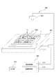
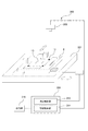
図1は実施の形態1のロボット装置の構成の説明図である。図1に示すように、ロボット装置1aは、制御部4がロボットアーム2、ロボットハンド3、及びフィンガー31を制御して、トレイ7内のワーク9aに対するピッキング作業を行う。ロボット装置1aは、ロボットアーム2によりトレイ7からワーク9aを取り出して、図示しない後工程に受け渡す。
<Embodiment 1>
(Robot device)
FIG. 1 is an explanatory diagram of the configuration of the robot apparatus according to the first embodiment. As illustrated in FIG. 1, in the robot apparatus 1 a, the
ロボットアーム2は、架台10に固定された6軸垂直多関節のロボットアームである。ロボットアーム2の先端に、ワーク9aを把持するロボットハンド3が固定されている。ロボットハンド3の先端にフィンガー31が固定されている。ロボットハンド3は、フィンガー31の開閉によってワーク9aを把持及びリリースする。
The
トレイ7のワーク9aが無くなると、搬送機構401は、ワーク9aが無くなったトレイ7を排出し、ワーク9aを収容した新しいトレイ7をロボットアーム2の可動範囲内に搬送してくる。新しいトレイ7がロボット装置1aの前に位置決め停止され、ロボットアーム2、ロボットハンド3、及びフィンガー31によってピッキング作業が再開される。
When the
制御部4は、ロボット装置1aを制御するコンピュータである。CPU41は、演算を行う。ROM42及びRAM43は、情報を記憶する。インターフェース部(I/F)44は、外部と通信を行う。CPU41、ROM42、RAM43、及びインターフェース部(I/F)44は、バス45を介して制御部4の内部で互いに通信可能である。
The
CPU41は、ロボット制御部411、ロボット動作補正演算部412、画像データ取得部(視覚センサ制御部)413、マーカー位置演算部414、誤差情報読取部415として機能する。これらの演算部及び制御部は、ROM42に記憶されたプログラムをCPU41に読み込むことによってCPU41内に一時的に形成される。プログラムは、光ディスク等の記録媒体によって制御部4にコピーされてもよい。
The
ロボットアーム2、ロボットハンド3、及びフィンガー31は、インターフェース部44を介してCPU41のロボット制御部411に電気的に接続されている。ロボット制御部411は、指令値を出力して、ロボットアーム2の各関節を駆動し、ロボットアーム2の位置姿勢を制御し、ロボットアーム2の先端部を6自由度に移動させる。ロボット制御部411は、指令値を出力して、ロボットハンド3の位置姿勢を調整する。ロボット制御部411は、指令値を出力して、フィンガー31の開閉動作を実行させる。
The
(座標系)
ロボットアーム2の基端部には、架台10に対するロボットアーム2の位置姿勢を代表する座標系としてロボット座標系Rが設定されている。ロボットハンド3の掌部には、ロボットハンド3の位置姿勢を表す手先座標系Tが設定されている。
(Coordinate system)
A robot coordinate system R is set at the base end of the
ロボット制御部411は、ロボット座標系Rを基準とする手先座標系Tの相対位置姿勢RHTの目標値(指令値)に対して、ロボットアーム2の各関節の取るべき角度目標値を算出する(逆運動学計算)。なお、ここで、ロボット座標系Rから手先座標系Tへの相対位置姿勢をRHTと表した。本明細書においては、任意の座標系Aから座標系Bへの相対位置姿勢及びその相対位置姿勢を表す座標変換行列をAHB又はAMBのように左肩と右下に座標系の記号を付与することによって表現する。
The
ロボット制御部411は、ロボットアーム2の各関節に設けられた図示しないエンコーダより出力される現在角度が角度目標値に一致するようにサーボ制御を行う。ロボット制御部411は、エンコーダから各関節の現在角度情報を取得し、ロボット座標系Rに対する手先座標系Tの現在の相対位置姿勢であるRHTを算出する(順運動学計算)。
The
ロボット装置1aは、工場でピッキング作業や組立作業を自動的に精度よく行うために、または治工具やワークに対するティーチングの位置調整を高精度かつ簡便に行うために、ロボットアーム2の位置調整と視覚センサによる計測とを組合せている。
The robot apparatus 1a adjusts and visually adjusts the position of the
ロボット装置1aは、視覚センサを用いてトレイ7を検知するビジョンシステムを搭載している。視覚センサとは、測定対象物の位置や姿勢を二次元的または三次元的に計測可能なセンサである。視覚センサを表す言葉として「ビジョン」「ロボットビジョン」「カメラ」などの表現が用いられる。実施の形態1において、視覚センサは、固定カメラ5のことである。
The robot apparatus 1a is equipped with a vision system that detects the
以上説明したように、保持部の一例である搬送機構401は、トレイ7をロボットアーム2による処理が可能な位置に保持する。撮像部の一例である固定カメラ5は、搬送機構401により保持されたトレイ7の少なくともマーカー11と誤差情報パターン12とを含む領域を撮像可能である。画像処理部の一例である誤差情報読取部415は、固定カメラ5により撮像された撮像画像を画像処理して、マーカー11の位置情報とマーカー11の位置ずれ情報とを取得する。調整部の一例である制御部4は、取得したマーカー11の位置情報とマーカー11の位置ずれ情報とに基づいてロボットアーム2の制御に用いる座標系を調整する。
As described above, the
(固定カメラ)
制御部4は、固定カメラ5の撮影画像を画像処理してトレイ7内のワーク9aの状態を検知する。固定カメラ5は、トレイ7の上空位置に設置され、トレイ7の上面を撮影する。固定カメラ5は、インターフェース部44を介してCPU41の画像データ取得部413に電気的に接続されている。
(Fixed camera)
The
画像データ取得部413は、固定カメラ5に対して撮像指令を出力し、固定カメラ5が撮影を行う。画像データ取得部413は、固定カメラ5に指令を出力してトレイ7の画像を撮影させ、固定カメラ5から画像データ取得部413へ画像データを送信させる。制御部4は、画像データ取得部413から画像データを取得してRAM43に一時保持する。
The image
固定カメラ5で撮像した撮像画像のピクセルデータを三次元の座標データに変換するためのカメラ内部パラメータ及び外部パラメータは、事前に取得されてROM42に記憶されている。画像データ取得部413は、取得した撮像画像の画像データをマーカー位置演算部414及び誤差情報読取部415に出力する。
Camera internal parameters and external parameters for converting pixel data of a captured image captured by the fixed
マーカー位置演算部414は、撮像画像の画像データを画像処理してマーカー11の位置情報を取得する。誤差情報読取部415は、撮像画像の画像データを画像処理して、トレイ7内のワーク9aに対するマーカー11の位置ずれ情報を取得する。
The marker
ロボット動作補正演算部412は、マーカー11の位置情報と位置ずれ情報とを用いて、ロボットアーム2を制御するための座標系を調整する。ロボット制御部411は、ロボット動作補正演算部412の演算結果に基づいて、マーカー11の位置ずれ方向及び位置ずれ量を相殺するように、ロボットアーム2、ロボットハンド3、及びフィンガー31を動作させる。
The robot motion
固定カメラ5のレンズ主点位置に、固定カメラ5の位置姿勢を代表する固定カメラ座標系Fが仮想的に設定されている。固定カメラ座標系Fから記述された三次元座標データをロボット座標系Rに変換するための校正データも事前に取得され、ROM42に記憶されている。
A fixed camera coordinate system F representing the position and orientation of the fixed
(トレイ)
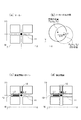
図2はトレイの構成の説明図である。図2中、(a)は斜視図、(b)は平面図である。図1に示すように、ロボット装置の一例であるロボット装置1aは、作業用基準物体の一例であるトレイ7を使用する。作業用基準物体の一例であるトレイ7は、ロボットアーム2を有するロボット装置で使用される。
(tray)
FIG. 2 is an explanatory diagram of the configuration of the tray. 2A is a perspective view, and FIG. 2B is a plan view. As shown in FIG. 1, a robot apparatus 1a that is an example of a robot apparatus uses a
図2の(a)に示すように、トレイ7は、ワーク9aを整列して収容し搬送する容器である。トレイ7は、ロボットアーム2によりワーク9aが取り出される容器である。トレイ7は、仕切りによってワーク9aを16個格納できる。トレイ7は、それぞれの仕切り内に、ワーク9aに対する不図示の突き当て部を有し、トレイ7に対してワーク9aを所定の精度範囲で位置決めできる。
As shown in FIG. 2A, the
図2の(b)に示すように、トレイ7の上面にマーカー11と誤差情報パターン12とが隣接して配置される。固定カメラ5の撮像画像は、トレイ7の上面の4つのマーカー11と、8つの誤差情報パターン12とを含む。
As shown in FIG. 2B, the
図1に示すように、トレイ7は、ロボット装置1aに合わせて新たに設計されたものが好ましい。しかし、実施の形態1では、ロボット装置1aを導入するにあたって人手作業で使用していたトレイ7、すなわち視覚センサによって計測されることを想定していないトレイ7を流用している。
As shown in FIG. 1, the
視覚センサによって計測されることを想定していないため、トレイ7は、固定カメラ5によって測定をおこなうことが難しく、マーカー11が必要となる可能性が高い。
Since it is not assumed to be measured by a visual sensor, it is difficult for the
トレイ7は、トレイ7の1つの面に、指標の一例であるマーカー11を複数配置している。マーカー11は、光学的に検知してロボットアーム2の制御に用いる座標系を調整可能である。マーカー11は、黒色円形のシールをトレイ7に貼り付けることによって実現している。
In the
(誤差情報の記録処理)
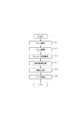
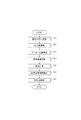
図3は誤差情報の測定記録装置の構成の説明図である。図4はトレイに対する誤差情報の記録処理のフローチャートである。実施の形態1では、ロボット装置1aの動作とは関係なく、別途事前に、図3に示す専用の誤差情報の測定記録装置300を用いてトレイ7に誤差情報を記録している。制御部304は、測定制御部313と、記録制御部314とを有する。
(Error information recording process)
FIG. 3 is an explanatory diagram of the configuration of the error information measurement recording apparatus. FIG. 4 is a flowchart of error information recording processing for the tray. In the first embodiment, regardless of the operation of the robot apparatus 1a, error information is recorded on the
図3に示すように、測定記録装置300は、支持部301にトレイ7の左側面と下側面を機械的に突き当てた状態で、測定顕微鏡305を用いて、トレイ7の基準位置に対するマーカー11の円の中心の座標値を測定する。測定工程の一例である誤差情報の測定処理では、測定制御部313がトレイ7における指標の位置ずれ情報を測定する。
As shown in FIG. 3, the
測定記録装置300は、測定制御部313が測定顕微鏡305により撮像されたトレイ7の撮像画像を画像処理して、マーカー11の位置ずれ情報を取得し、位置ずれ情報を誤差情報パターン12として出力部316から出力する。記録工程の一例である誤差情報の記録処理では、記録制御部314が、誤差情報の測定処理により測定した指標の位置ずれ情報を、光学的に読み取り可能な情報画像の一例である誤差情報パターン12に変換してトレイ7に記録する。これにより、実施の形態1のトレイ7が製造される。
In the
図3を参照して図4に示すように、ユーザーは、マーカー11を付与する前のトレイ7本体を準備し、測定記録装置300の支持部301にセットする(S01)。ユーザーは、支持部301にセットされたトレイ7にマーカー11を貼り付ける(S02)。
As shown in FIG. 4 with reference to FIG. 3, the user prepares the
ユーザーは、支持部301にセットされたトレイ7にワーク(9a)の測定用ダミー309aをセットして測定記録装置300の不図示の測定開始ボタンを押す。すると、測定記録装置300は、測定用ダミー309aを撮像して、トレイ7の基準位置に対するマーカー11の取り付け位置の位置ずれ量を測定する(S03)。測定用ダミー309aには、測定用の等間隔のメッシュと中心位置とが形成されている。測定制御部313は、測定用ダミー309aをセットしたトレイ7の測定顕微鏡305を通じた撮像画像から、トレイ7においてマーカー11が配置されるべき基準位置を求める。そして、4つのマーカー11ごとに基準位置と現在のマーカー位置との位置ずれ量を求める。
The user sets the
記録制御部314は、後述する定義に合致した誤差情報パターン12をラベルシールとして作成し、出力部316から印刷出力する。測定記録装置300は、マーカー11ごとの位置ずれ情報を算出し、マーカー11の誤差量(ΔX、ΔY)に応じた誤差情報パターン12を作成し、出力部316から印刷出力する(S04)。
The
ユーザーは、支持部301にセットされたトレイ7のマーカー11に近接した位置に、マーカー11ごとの誤差情報パターン12を貼り付ける(S05)。このようにして、トレイ7に対するマーカー11及び誤差情報パターン12の加工が完了する。
The user pastes the
マーカー11の位置誤差は、マーカー11をトレイ7に貼付することで初めて発生した誤差である。そして、マーカー11の位置誤差情報は、マーカー11をトレイ7に貼付することで初めて発生した情報である。誤差情報パターン12は、マーカー11の位置誤差情報を反映している。誤差情報パターン12は、マーカー11がトレイ7に設けられた後に、マーカー11の測定結果に応じてトレイ7に記録される。
The position error of the
したがって、マーカー11と誤差情報パターン12は、独立している。「独立」とは、「マーカー11を加工した後に、誤差情報パターン12を別個に設けることができる」、「誤差情報パターン12の保持する位置ずれ情報をマーカー11の位置情報と別個に読み取ることができる」という意味である。
Therefore, the
例えば、マーカー11と誤差情報パターン12を同時に1枚のラベルシールに印刷してトレイ7に貼り付けた場合は独立でない。しかし、ドーナツ状に作成したマーカー11の内側に誤差情報パターン12を取り付ける場合は独立である。
For example, the case where the
(誤差情報パターン)
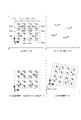
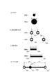
図5はトレイの1つのマーカー周辺の拡大図である。図5中、(a)はマーカー、(b)はマーカーの拡大図、(c)は誤差情報パターン、(d)は誤差情報パターンの検出範囲である。
(Error information pattern)
FIG. 5 is an enlarged view around one marker on the tray. In FIG. 5, (a) is a marker, (b) is an enlarged view of the marker, (c) is an error information pattern, and (d) is a detection range of the error information pattern.
図5の(a)に示すように、トレイ7の基準位置としてトレイ7の左下の点を採用する。図5の(b)に示すように、トレイ7の基準位置に仮想的に設定するトレイ座標系Wからみた測定結果の座標値を(XR,YR)とし、マーカー位置の座標値の設計値を(XD、YD)とする。このとき、マーカー位置の誤差量(ΔX、ΔY)は次式のように計算される。
As shown in FIG. 5A, the lower left point of the

図5の(c)に示すように、誤差情報パターン12は、マーカー位置の誤差量(ΔX、ΔY)に比例した長さを有する矩形形状として定義した。誤差情報パターン12の矩形の長さΔL1及びΔL2は、マーカー位置誤差ΔX、ΔYの絶対値の50倍の長さとなるように定義している。また、マーカー11に対する誤差情報パターン12の取り付け位置が、誤差方向(すなわち、ΔX、ΔYの正負)と対応している。
As shown in FIG. 5C, the
![]()
![]()
図2の(b)に示すように、トレイ7は、情報画像の一例である誤差情報パターン12を有する。誤差情報パターン12は、トレイ7のマーカー11が配置された面において対応するマーカー11に隣接させて配置され、光学的に検知してトレイ7に対するマーカー11の位置ずれ情報を取得可能である。位置ずれ情報は、トレイ7に対する指標の位置ずれ方向及び位置ずれ量である。誤差情報パターン12は、マーカー11を中心とする直交座標における位置ずれ方向に対応する座標軸の方向に、位置ずれ量の座標軸方向成分に対応する長さを持つ。
As shown in FIG. 2B, the
(ロボットアームを制御するための座標の調整)
図6はロボットアームの調整制御のフローチャートである。プログラムを読み込んだコンピュータである制御部4は、誤差情報パターン(12:図2)を用いてロボットアーム2によるトレイ7上の作業位置を調整する。
(Coordinate adjustment to control the robot arm)
FIG. 6 is a flowchart of robot arm adjustment control. The
図1を参照して図6に示すように、制御部4は、保持工程において、搬送機構401によって、トレイ7がロボットアーム2の可動範囲内に搬送されてくることを検知する(S11)。保持工程では、搬送機構401により、トレイ7をロボットアーム2による処理が可能な位置に保持させる。
As shown in FIG. 6 with reference to FIG. 1, the
制御部4は、検知工程において、画像データ取得部413により、固定カメラ5を制御して、トレイ7及びワーク9aを撮影する(S12)。制御部4は、画像データ取得部413により取得した画像データを、マーカー位置演算部414により画像処理して、マーカー11の位置を取得する(S13)。検知工程では、搬送機構401により保持されたトレイ7のマーカー11を、検知部の一例である固定カメラ5により検知して指標の位置を取得する。
In the detection step, the
制御部4は、読取工程において、画像データ取得部413により取得した画像データを、誤差情報読取部415により画像処理して、マーカー11の誤差情報を取得する(S14)。読取工程では、搬送機構401により保持されたトレイ7の誤差情報パターン12を、読取部の一例である固定カメラ5により読み取ってマーカー11の位置ずれ情報を取得する。
In the reading process, the
制御部4は、調整工程において、マーカー位置演算部414が取得したマーカー11の位置と誤差情報読取部415が取得したマーカー11の誤差情報とを用いて、ロボットアーム2を制御するための座標系の補正量を計算する(S15)。調整工程では、ロボット動作補正演算部412が、検知工程により取得したマーカー11の位置と、読取工程により取得したマーカー11の位置ずれ情報と、に基づいて、ロボットアーム2を制御するための座標系を調整する。
The
制御部4は、ロボット動作補正演算部412により補正された座標系を用いて、ロボット制御部411によりロボットアーム2及びロボットハンド3を制御して、トレイ7内のワーク9aのピッキング作業を行う(S16)。
The
(マーカー位置演算処理)
マーカー位置演算部414は、固定カメラ5により撮影した4つのマーカー11を含む画像全体を二値化処理する。そして、二値化処理画像上で、真円度や外接円半径などの形状特徴量からマーカー11の領域を特定してマーカー11のエッジ画像を抽出する。その後、マーカー11のエッジ画像を円弧フィッティング処理することにより、高精度にマーカー11の中心を算出する。
(Marker position calculation processing)
The marker
マーカー位置演算部414は、ピクセル単位の座標データに対して、事前に校正した固定カメラ5の内部パラメータ及び外部パラメータを適用することによって、実スケール(例えばmm単位)に換算したマーカー11の位置の値(X,Y)を算出する。
The marker
(誤差情報読取処理)
誤差情報読取部415は、固定カメラ5により撮影した4つの誤差情報パターンを含むトレイ7の撮影画像の画像データに対して画像処理を行って、パターン12の位置及び長さを測定することにより、マーカー11の誤差情報を取得する。
(Error information reading process)
The error
図5の(d)に示すように、誤差情報パターン12は、マーカー11を中心とする4つのエリアを画像認識することで、その長さを測定することができる。
As shown in FIG. 5D, the length of the
マーカー位置演算部414により取得したマーカー11の位置を基準として、点線で示す誤差情報パターン12の存在候補領域に対して検出処理を行うことにより、誤差情報パターン12の有無を検知する。このとき、マーカー11に対して−X側と+Y側に誤差情報パターン12が検出されるので、それによって誤差の正負情報を取得する。
The presence / absence of the
次に、検出された誤差情報パターン12の内部の黒色矩形に対して測定を行い、長さL1及びL2を算出する。最後に、誤差情報パターン12の長さ定義の逆演算を行うことによって、マーカー11の位置誤差情報を算出する。
Next, measurement is performed on the black rectangle inside the detected
![]()
![]()
このようにして、誤差情報読取部415は、1つのマーカー11における誤差情報パターン12に埋め込まれたマーカー11の位置誤差情報を読み取る。誤差情報読取部415は、同様な手順で、図2の(b)に示すトレイ7上の4つのマーカー11におけるそれぞれの誤差情報パターン12を検知して、トレイ7上の4点分の位置誤差情報を読み取る。
In this way, the error
(ロボット動作補正演算処理)
図7はロボット動作補正演算処理の説明図である。図7中、(a)は設計データ、(b)は測定データ、(c)はトレイ形状データ、(d)は補正結果データである。
(Robot motion compensation calculation processing)
FIG. 7 is an explanatory diagram of the robot motion correction calculation process. In FIG. 7, (a) is design data, (b) is measurement data, (c) is tray shape data, and (d) is correction result data.
図1に示すように、ロボット動作補正演算部412は、4つのマーカー11に対応するトレイ7上の4点でのフィッティング処理によってトレイ7に収容されたワーク9aの位置と角度を計算する。
As shown in FIG. 1, the robot motion
図7の(a)に示すように、前提として、ロボット動作補正演算部412は、設計データを保有している。すなわち、トレイ座標系Wに対するマーカー11の位置の設計値PD1〜PD4、トレイ座標系Wに対するロボットのティーチングポイントの狙い位置であるTP11〜TP44、そしてロボット座標系Rに対するトレイ座標系Wの設計位置である。
As shown in FIG. 7A, as a premise, the robot motion
マーカー位置演算部414が算出したマーカー位置データは、固定カメラ5の座標系からみた測定値であるため、そのままロボットの補正に用いることはできない。そのため、ロボット動作補正演算部412は、マーカー位置演算部414が算出したマーカー位置データに対して座標変換を行い、図7の(b)に示すように、ロボット座標系Rにおける4つのマーカー11の座標値PM1〜PM4に変換する。
The marker position data calculated by the marker
なお、そのために必要な事前に特定したロボット座標系Rと固定カメラ座標系Fの関係は、前述した校正により事前に取得されている。 It should be noted that the relationship between the robot coordinate system R and the fixed camera coordinate system F specified in advance necessary for this purpose is acquired in advance by the calibration described above.
ロボット動作補正演算部412は、誤差情報読取部415が出力したマーカー11の位置誤差情報を受け取り、設計データに位置誤差情報を加味したマーカー位置データを算出する。
The robot motion
具体的な処理としては、図7の(a)に示すように、4点のマーカー11に対する位置誤差情報(ΔX[i],ΔY[i])(i=1,2,3,4)を設計上のマーカー位置の設計値PD1〜PD4に加算することで補正する。補正されたマーカー位置データをトレイ座標系Wからみた座標値をPR1〜PR4とする。
Specifically, as shown in FIG. 7A, position error information (ΔX [i], ΔY [i]) (i = 1, 2, 3, 4) with respect to the four
ロボット動作補正演算部412は、トレイ座標系Wからみた補正後のマーカー位置データの座標値PR1〜PR4を、ロボット座標系Rからみたマーカー測定データの座標値PM1〜PM2に重ねるように座標変換する座標変換パラメータ(tx、ty、θ)を求める。
Robot operation
具体的な処理としては、図7の(c)に示すように、座標変換パラメータ(tx、ty、θ)によって座標値PR1〜PR4を座標変換した後の座標値と、マーカー測定データの座標値PM1〜PM4の座標値の距離の二乗和が最小となるように、座標変換パラメータ(tx、ty、θ)を求める。
As specific processing, as shown in FIG. 7C, coordinate values after coordinate conversion of coordinate values P R 1 to
すなわち、座標変換パラメータ(tx、ty、θ)による座標変換を同次変換行列H(tx、ty、θ)と表した場合に、次式となるような座標変換パラメータ(tx、ty、θ)を最小二乗法によって求める。次式中、座標値PM[i]およびPR[i]を、二次元の同次ベクトルT(XM[i],YM[i],1),T(XR[i],YR[i],1)で表現した。 That is, when the coordinate transformation by the coordinate transformation parameters (tx, ty, θ) is expressed as a homogeneous transformation matrix H (tx, ty, θ), the coordinate transformation parameters (tx, ty, θ) as shown in the following equation: Is obtained by the method of least squares. In the following equation, coordinate values P M [i] and P R [i] are converted into two-dimensional homogeneous vectors T (X M [i], Y M [i], 1), T (X R [i], Y R [i], expressed in 1).
ロボット動作補正演算部412は、座標変換パラメータ(tx、ty、θ)を用いて、ロボットのティーチングポイントデータTP11〜TP44を座標変換することにより補正演算して処理を終了する。
The robot motion
(比較例)
比較例1では、特許文献1に示されるように、トレイ、治工具、ワークなどの対象物に設けたマークを基準として、ロボットアーム2の教示位置データを補正する。
(Comparative example)
In Comparative Example 1, as shown in Patent Document 1, the teaching position data of the
比較例1では、トレイ、治工具、ワークなどの対象物に設けられた指標に対してロボットアーム2による処理位置の補正を行う。しかし、実際には、対象物の個体ごとに加工誤差等によるマーカー位置誤差があるために、高精度に補正を行うことが難しい。
In the first comparative example, the processing position of the
比較例2では、特許文献2に示されるように、アライメントマークの位置関係を事前に測定機を用いて測定した誤差データを用いてトレイ、治工具、ワークなどの位置調整を高精度に行う。高精度に補正を行うためには、マーカーの位置誤差をキャンセルするために、事前に測定した個体ごとの測定データをサーバーに保持する必要がある。
In Comparative Example 2, as shown in
しかし、この方法を単純に適用すると、対象物個体差ごとの測定データを管理して紐づける必要があるため、工場内の汎用トレイなどのように数が多い場合や、消耗による追加がある場合や、装置の数が多い場合は管理負荷やミスの可能性が大きくなる。 However, if this method is simply applied, it is necessary to manage and link the measurement data for each individual object difference, so there are many cases such as general-purpose trays in the factory, or addition due to consumption If the number of devices is large, the management load and the possibility of mistakes increase.
サーバーで一括管理して装置間ネットワークを構築したり、誤差情報のデータベースを装置内に構築したりすると、システムの大規模化が必要である。 If a network is managed by a server and a network between devices is built or a database of error information is built in a device, the system needs to be scaled up.
また、別の方法として、トレイごとにメモリタグを設け、事前に測定した誤差データをトレイごとに記録し、読み取って誤差データを使用することが考えられる。しかし、この場合、メモリタグの書き込み装置、読取装置が必要となる。 As another method, a memory tag may be provided for each tray, and error data measured in advance may be recorded for each tray and read to use the error data. In this case, however, a memory tag writing device and reading device are required.
(実施の形態1の効果)
実施の形態1では、対象物に独立に付与された位置測定用のマーカーと誤差情報保持パターンの両方を同一の視覚センサによって読み取って誤差を補正する構成とした。このため、専用のセンサや誤差情報を保持するサーバーなどを設けない簡素なシステム構成でありながら、対象物に対するマーカーの取り付けや加工の位置誤差をキャンセルして高精度なロボット動作を実現することができる。
(Effect of Embodiment 1)
In the first embodiment, the error is corrected by reading both the position measurement marker and the error information holding pattern independently given to the object by the same visual sensor. For this reason, it is possible to realize a highly accurate robot operation by canceling marker attachment and machining position errors on the target object, while having a simple system configuration that does not include a dedicated sensor or server that stores error information. it can.
実施の形態1では、補正データは、トレイ7の位置姿勢の補正に加えて、トレイ7に対するマーカー11の位置誤差もキャンセルしている。このため、フィンガー31をワーク9aに対して高精度にアプローチさせて作業を行うことができる。
In the first embodiment, the correction data cancels the position error of the
実施の形態1では、トレイ7の個体差情報を管理するためのサーバーやデータベースを設けることなく、簡素な構成でワーク9aの高精度なピックアップ作業が可能となる。
In the first embodiment, the
実施の形態1では、誤差の量と誤差情報保持パターン12の長さとを対応させ、誤差の方向と誤差情報保持パターン12の向きとを対応させているため、作業者がトレイ7を見た際に、誤差の量と方向とを直感的に理解できる。
In the first embodiment, the error amount and the length of the error
実施の形態1では、トレイ7上のマーカー11に対して個体差をキャンセルして高精度な作業が可能なロボット装置1aを簡素な構成で実現できる。
In the first embodiment, the robot apparatus 1a capable of canceling the individual difference with respect to the
<実施の形態2>
図8は実施の形態2における誤差情報の測定記録装置の構成の説明図である。図9は実施の形態2のロボット装置の構成の説明図である。実施の形態2では、図8に示すように、測定記録装置300を用いて、ワーク保持具8にマーカー11と二次元コード13とを取り付ける。そして、図9に示すように、ワーク保持具8に設けられたマーカー11と二次元コード13とを手先カメラ6により撮像して、ロボットアーム2のティーチングを行っている。これ以外の構成及び制御内容は実施の形態1と同一であるため、図8、図9中、実施の形態1と共通の構成には図3、図1と同一の符号を付して重複する説明を省略する。
<
FIG. 8 is an explanatory diagram of the configuration of the error information measurement recording apparatus according to the second embodiment. FIG. 9 is an explanatory diagram of a configuration of the robot apparatus according to the second embodiment. In the second embodiment, as shown in FIG. 8, the
(測定記録装置)
図8に示すように、ユーザーは、専用の誤差情報の測定記録装置300を用いて、マーカー11が取り付けられたワーク保持具8に誤差情報を記録する。測定記録装置300は、マーカー11が取り付けられたワーク保持具8の左側面と下側面を支持部301に突き当てた状態で、測定顕微鏡305を用いて、ワーク保持具8の基準位置に対するマーカー11の中心座標値を測定する。
(Measurement recording device)
As shown in FIG. 8, the user records error information on the
測定制御部313は、測定顕微鏡305により撮像されたワーク保持具8の撮像画像を画像処理して、マーカー11の位置ずれ情報を取得する。記録制御部314は、位置ずれ情報を二次元コード13に変換して出力部316からプリントアウトする。ユーザーは、マーカー11が取り付けられたワーク保持具8に二次元コード13を貼付する。
The
(ロボット装置)
図9に示すように、ロボット装置1bは、制御部4がロボットアーム2、ロボットハンド3、及びフィンガー31を制御して、ワーク保持具8に保持されるワークに対する組立作業を行う。ロボット装置1bは、ロボットアーム2によりワーク保持具8にワークを取り付け、ワークに対して他の部品を組み立てる作業を実行する。
(Robot device)
As shown in FIG. 9, in the
(手先カメラ)
図9に示すように、ロボット装置1bでは、固定カメラ5ではなく手先カメラ6を用いている。手先カメラ6は、ロボットアーム2の先端のロボットハンド3に取り付けられた2眼のステレオカメラである。
(Hand camera)
As shown in FIG. 9, the
手先カメラ6は、ロボットアーム2のティーチング時にのみロボットハンド3に取り付けられ、実際のワーク(9b:図10の(b))に対する組み立て作業時にはロボットハンド3から取り外し可能である。手先カメラ6は、事前にカメラ単体でキャリブレーションされており、二眼のカメラのうち一方のレンズ主点に仮想的に設定された手先カメラ座標系Vを基準として、画像上の任意の特徴点の三次元座標を測定することができる。手先カメラ6は、ロボットアーム2との間で事前のキャリブレーションが行われており、手先座標系Tと手先カメラ座標系Vの関係が事前に算出されている。
The hand camera 6 is attached to the
(ワーク保持具)
図10は実施の形態2におけるワーク保持具の構造の説明図である。図10中、(a)はワーク非装着状態、(b)はワーク装着状態である。
(Work holder)
FIG. 10 is an explanatory diagram of the structure of the work holder in the second embodiment. In FIG. 10, (a) is a work non-mounting state, (b) is a work mounting state.
図9に示すように、ロボット装置1bにおけるロボットアーム2の可動範囲内にワーク保持具8が設置されている。作業用基準物体の一例であるワーク保持具8は、ロボットアーム2によりワーク9bが取り付けられる治工具である。ワーク保持具8は、着脱部402によって作業台403に対して着脱可能に取り付けられている。
As shown in FIG. 9, a
図10の(a)に示すように、ワーク保持具8は、突き当て部81、82と、クランプ部83、84を有している。ワーク保持具8の1つの面に指標の一例であるマーカー11が複数配置される。
As shown in FIG. 10A, the
ワーク保持具8は、3点のマーカー11の中央に、3点のマーカー11の位置ずれ情報を含む1つの二次元コード13を設けている。情報画像の一例である二次元コード13は、マーカー11が配置された面においてマーカー11から離れて配置され、複数のマーカー11の位置ずれ情報を含む。二次元コード13は、二次元コード化された文字情報(数字を含む)である。
The
図10の(b)に示すように、クランプ部83、84は、図示しない直動機構によってワーク9bをクランプする。図9に示すように、ロボット装置1bは、ロボットアーム2及びロボットハンド3によって、図10の(b)に示すようにワーク9bをワーク保持具8に載置する。ロボット装置1bは、その後、クランプ部83、84にクランプ動作を行わせて、クランプ部83、84と突き当て部81、82との間にワーク9bを挟み込んで保持する。
As shown in FIG. 10B, the
これにより、ワーク9bは、突き当て部81、82を基準として、ワーク保持具8に対して所定の精度と再現性で位置決めされる。ロボット装置1bは、ワーク9bをワーク保持具8に保持させたあと、ロボットアーム2とロボットハンド3を用いて、図示しない別部品をワーク9bに組み付ける動作を実行する。
Thus, the
(ワーク保持具の精度)
図9に示すように、ロボット装置1bは、ワーク保持具の交換時には、ワーク保持具8を取り外して、別のワークを対象とした別のワーク保持具をロボット装置1bに取り付ける。ロボット装置1bに相当するロボットシステムは、工場内に複数存在しており、ワーク保持具8と同じ設計のワーク保持具が複数存在する。そして、工場内の生産の状況やメンテナンスの状況に応じてワーク保持具8を別の場所のロボット装置に取り付けて使用する場合がある。
(Accuracy of workpiece holder)
As shown in FIG. 9, when exchanging the workpiece holder, the
ロボット装置1bが精度よくワーク9bに対して別部品の組み付けを実施するためには、組付作業前に、ロボットアーム2のティーチングポイントを高精度に調整しておく必要がある。特に、ワーク保持具8を交換した直後には、ワーク保持具8の加工個体差があるためにティーチングが重要となる。したがって、実施の形態2は、ロボット装置1bにおけるティーチングポイントの調整を対象とする。ロボットアーム2によるワーク保持具8上のティーチングされた作業位置が二次元コード13から復号された位置ずれ情報によって修正される。
In order for the
(ロボットアームのティーチング)
図11はロボットアームのティーチング制御のフローチャートである。実施の形態2では、ユーザーが事前に撮影可能なティーチングポイントを登録しておいて、制御部4がプログラムによりロボットアーム2を制御して移動させる。
(Robot arm teaching)
FIG. 11 is a flowchart of teaching control of the robot arm. In the second embodiment, teaching points that can be photographed by the user are registered in advance, and the
図11に示すように、制御部4は、ロボット制御部411によりロボットアーム2を制御して、手先カメラ6がワーク保持具8を撮影可能な位置にロボットアーム2を移動させる(S21)。
As shown in FIG. 11, the
制御部4は、画像データ取得部413により手先カメラ6を作動させてワーク保持具8を撮像してワーク保持具8の画像データを取得する(S22)。制御部4は、マーカー位置演算部414によりワーク保持具8の画像データを画像処理して、マーカー11の位置を算出する(S23)。
The
制御部4は、誤差情報読取部415により画像データに対して画像処理を実行して、マーカー11の位置誤差情報を読み取る(S24)。制御部4は、ロボット動作補正演算部412がロボットの補正計算を行う(S25)。
The
制御部4は、ロボット動作補正演算部412により算出された後述する同次変換行列RMTを指令値としてロボットを動作させることにより、ロボットハンド3の位置を調整する(S26)。制御部4は、ロボットハンド3の位置を調整して位置決めした状態でロボットの姿勢をティーチングポイントとして登録する(S27)。
The
(マーカー位置演算処理)
画像データ取得部413は、マーカー11及び二次元コード13を有するワーク保持具8の画像データを取得する処理を実施の形態1と同様に実行する。しかし、手先カメラ6が二眼のステレオカメラであるために、1回の撮影ごとに2枚の画像が取得され、焦点距離方向の情報を取得することができる。
(Marker position calculation processing)
The image
マーカー位置演算部414は、画像データ取得部413が取得した画像データ上でマーカー11の位置を算出する処理を実施の形態1と同様に実行する。しかし、手先カメラ6が二眼のステレオカメラであるために、マーカー11の位置を三次元的に算出することができる。
The marker
マーカー位置演算部414は、事前にキャリブレーションした手先カメラ6の校正データを用いて、3点のマーカー11に対して、それぞれ三次元の座標値を算出する。その座標値の同次ベクトルを次式であらわす。次式中、座標値PM[i]は手先カメラ座標系Vからみたマーカー11の座標値である。
The marker
![]()
![]()
(誤差情報読取処理)
図12はマーカー位置誤差データの二次元コードの説明図である。図9に示すように、誤差情報読取部415は、二次元コード13の画像データを画像処理して、マーカー11の位置誤差情報を取得する。誤差情報読取部415は、ワーク保持具8を撮像した画像データ内の二次元コード13を復号することによって誤差情報を取得する。
(Error information reading process)
FIG. 12 is an explanatory diagram of a two-dimensional code of marker position error data. As illustrated in FIG. 9, the error
図12に示すように、二次元コード13には、実施の形態1と同様に、別途事前に測定記録装置300を用いて測定したマーカー11の位置誤差を測定したマーカー位置誤差データが格納されている。マーカー位置誤差データは、3点のマーカー11の座標値の設計値PD1〜PD3と、マーカー11の位置を事前に測定記録装置300で測定した測定値の座標値PR1〜PR3の差分として定義される。
As shown in FIG. 12, the two-
二次元コード13を復号すると、例えば表1に示すような、各点に対する誤差情報のテーブルデータを読みとることができる。
When the two-
二次元コード13の読み取りによって、3点のマーカー11の誤差情報ΔP[i](i=1,2,3)が取得される。ここで、ΔP[i]は三次元のデータをもつ4行1列の同次ベクトルである。なお、設計値PD1〜PD3及び測定値の座標値PR1〜PR3の値は、ワーク保持具8の突き当て部81、82と、ワーク保持具8のワーク載置面から定義されるワーク保持具座標系Jからみた座標値として表現されていてもよい。
By reading the two-
(ロボット動作補正演算処理)
ロボット動作補正演算部412は、補正計算の具体的な方法として、マーカー位置演算部414の出力したマーカー計測値の座標値PM[i](i=1,2,3)を、手先座標系Tからみた座標値に座標変換する。そのためには、事前に校正により取得した手先座標系Tと手先カメラ座標系Vの関係を、THVを用いて次式のように計算する。
(Robot motion compensation calculation processing)
The robot motion
![]()
![]()
なお、ここで、ロボット座標系Rから手先座標系Tへの同次変換行列をRHTとし、手先座標系Tから手先カメラ座標系Vへの同次変換行列をTHVと記載した。また、座標値PM[i]についてはどの座標系からみた座標値かが明確になるよう、基準とする座標系を文字の左肩に記載した。VPM[i]は手先カメラ座標系Vからみたマーカー測定値の座標値(すなわち、ステップS23で算出した座標値PM[i])であり、RPM[i]は同じ点をロボット座標系Rからみた座標値である。 Here, the homogeneous transformation matrix from the robot coordinate system R to the hand coordinate system T is denoted as R H T, and the homogeneous transformation matrix from the hand coordinate system T to the hand camera coordinate system V is denoted as T H V. The coordinate system P M [i] is described on the left shoulder of the character so that the coordinate value seen from which coordinate system is clear. V P M [i] is the coordinate value of the marker measurement value viewed from the hand camera coordinate system V (that is, the coordinate value P M [i] calculated in step S23), and R P M [i] is the same point as the robot. This is a coordinate value viewed from the coordinate system R.
また、ロボット座標系Rから手先座標系Tへの同次変換行列RHTは、撮影時のロボット姿勢を表し、ロボット制御部411がロボットアーム2の各関節角度から順運動学演算をおこなうことなどにより算出できる。
The homogeneous transformation matrix R H T from the robot coordinate system R to the hand coordinate system T represents the robot posture at the time of shooting, and the
次に、ロボット動作補正演算部412は、マーカー位置誤差情報を用いてマーカー設計値情報を補正する。マーカー11のワーク保持具座標系Jに対する座標値の設計値PD1〜PD3はあらかじめROM42に格納されている。座標値の設計値PD1〜PD3に誤差情報読取部415が読み取った誤差情報ΔP[i](i=1,2,3)を加算することによって、現在使用しているワーク保持具8固有の寸法値である座標値PR1〜PR3を算出する。この座標値PR1〜PR3はワーク保持具座標系Jを基準に記述されたものであるので、その同次ベクトルをJPR[i]と記述すると次式として算出できる。
Next, the robot motion
最後に、マーカー位置演算部414によるマーカー11の測定値を基にした座標値JPMと、ワーク保持具8の設計値にマーカー11の位置誤差を加味した座標値JPRを用いて、ロボットアーム2の取るべき位置姿勢を算出する。
Finally, by using the coordinate values J P M based on a measured value of the
ここで、ワーク保持具座標系Jに対する手先座標系Tの取るべき位置姿勢は事前に設計する事項であり、その既知の座標変換行列をTMJとする。また、ワーク保持具座標系Jと手先座標系Tの関係をTMJに近づけるためにロボットアーム2が取るべき未知の姿勢を表す三次元の同次変換行列RMTと書くこととする。このとき、以下の最小二乗法を解くことによって、同次変換行列RMTを求めることができる。
Here, the position and orientation of the hand coordinate system T to be taken with respect to the workpiece holder coordinate system J is an item to be designed in advance, and its known coordinate transformation matrix is T M J. In addition, in order to bring the relationship between the workpiece holder coordinate system J and the hand coordinate system T closer to T M J , a three-dimensional homogeneous transformation matrix R M T representing an unknown posture that the
上式の中で未知の変数は同次変換行列RMTだけであり、その他の変数はこれまでの処理により既知である。同一直線状にない3点以上のデータがあれば、6自由度の未知数である同次変換行列RMTの最小二乗解を算出することができる。 Unknown variables in the above formula is only homogeneous transformation matrix R M T, the other variables are known by the processing so far. If there are three or more data not in the same straight line, it is possible to calculate the least-squares solution of homogeneous transformation matrix R M T which is a six degrees of freedom unknown.
(実施の形態2の効果)
実施の形態2では、ワーク保持具8に対するマーカー11の位置ずれ誤差を相殺してロボットアーム2をティーチングすることができるため、マーカー11の位置ずれ誤差を相殺しない場合に比べて高精度なロボットアーム2の位置決めができる。
(Effect of Embodiment 2)
In the second embodiment, since the
実施の形態2では、マーカー11から離れた位置に設けた二次元コード13に3つのマーカー11の位置誤差情報をまとめて持たせるため、高精度な補正を、ワーク個体差情報をサーバーやデータベースに持たせる必要のない簡素な構成で実現可能である。
In the second embodiment, since the two-
<実施の形態3>
図13は実施の形態3のワーク保持具におけるマーカーの説明図である。図14は実施の形態3のワーク保持具における誤差情報保持パターンの説明図である。図13中、(a)はワーク保持具の斜視図、(b)は深さ方向の断面図、(c)はマーカーピンの斜視図である。図14中、(a)は誤差情報の未記録状態、(b)は誤差情報の記録状態である。
<
FIG. 13 is an explanatory diagram of markers in the work holder of the third embodiment. FIG. 14 is an explanatory diagram of an error information holding pattern in the work holder of the third embodiment. In FIG. 13, (a) is a perspective view of the workpiece holder, (b) is a sectional view in the depth direction, and (c) is a perspective view of the marker pin. In FIG. 14, (a) shows an unrecorded state of error information, and (b) shows a recorded state of error information.
実施の形態2では、ワーク保持具の基準面に沿った平面内のマーカーの位置ずれ量を二次元コード化してワーク保持具に貼付した。これに対して、実施の形態3では、ワーク保持具の基準面の高さ方向のマーカーの位置ずれ量を誤差情報保持パターンとしてマーカーに記録する。ワーク保持具(8b:図13)の誤差情報を用いて、マーカー(15:図13)の深さ方向の座標系を補正する。これ以外の構成及び制御内容は実施の形態2と同一であるため、図8、図9を参照して説明する。 In the second embodiment, the amount of positional deviation of the marker in the plane along the reference plane of the workpiece holder is two-dimensionally encoded and attached to the workpiece holder. In contrast, in the third embodiment, the amount of marker displacement in the height direction of the reference surface of the work holder is recorded on the marker as an error information holding pattern. Using the error information of the workpiece holder (8b: FIG. 13), the coordinate system in the depth direction of the marker (15: FIG. 13) is corrected. Since other configurations and control contents are the same as those in the second embodiment, description will be made with reference to FIGS.
(ワーク保持具)
図13の(a)に示すように、作業用基準物体の一例であるワーク保持具8bは、4か所の基準穴14に対してそれぞれマーカーピン15が挿入されている。ユーザーは、ワーク保持具8b上に基準穴14を高精度に加工した後、高精度に製作されたマーカーピン15を手作業で基準穴14に挿入している。マーカーピン15の固定に関して、基準穴14とマーカーピン15との間の公差の関係をしまり嵌めとなるように設計して、圧入してもよい。また、両者をゆるみ嵌めとして、接着剤等により固定してもよい。
(Work holder)
As shown in FIG. 13A, the
指標用部材の一例であるマーカーピン15は、ロボットアーム2とワーク保持具8bを有するロボット装置1aで使用される。嵌合部の一例である嵌合部19は、ワーク保持具8bの有する穴部と嵌合する。
The
指標部の一例であるマーカー部16は、光学的に検知してロボットアーム2の制御に用いる座標系を調整可能である。一方、情報画像記録部の一例である誤差情報記入部17は、光学的に読み取ってワーク保持具8bに対する指標の位置ずれ情報を取得可能な情報画像をマーカー部16とは独立に記録可能である。
The
図13の(b)に示すように、ワーク保持具8bの基準面から後退させて後退方向の位置情報を取得可能な指標の一例であるマーカー部16が配置される。基準穴14は、段付きのザグリ穴形状である。基準穴14には、マーカーピン15の段付き部が深さ方向に突き当たるところまで、マーカーピン15が挿入されている。マーカーピン15は、嵌合部19によって、基準穴14に対して所定の精度で嵌合し、位置決めされている。
As shown in FIG. 13 (b), a
図13の(b)に示すように、基準穴14は、ザグリ深さLaがマーカーピン15の段付き部の厚さLbよりも長く設計されている。このため、マーカーピン15の上面は、ワーク保持具8bの基準面から突出せず、むしろ後退している。
As shown in FIG. 13B, the
図13の(c)に示すように、マーカーピン15は、段付き形状を有する円筒形状のピンである。マーカーピン15の上面には、クロスマーク形状を付与したマーカー部16と、誤差情報記入部17とが形成されている。マーカー部16は、クロスマークの交点がマーカーピン15の中心軸線と所定の精度で一致している。
As shown in FIG. 13C, the
図14の(a)に示すように、マーカーピン15は、その上面に、マーカー部16を囲うように円周状に配置された誤差情報記入部17を有している。誤差情報記入部17は、一定間隔の実線または点線の目盛りにより区切られたマス目を有している。誤差情報記入部17は、1マスが10μmの深さ寸法を表しており、16マスの領域により、0〜160μmの深さを表現できるようになっている。
As shown in FIG. 14A, the
実施の形態3では、位置ずれ情報は、基準面からマーカー部16までの後退量である。情報画像の一例である誤差情報保持パターン18は、マーカー部16を囲んで配置された基準面からマーカー部16までの後退量に応じた長さの円弧である。
In the third embodiment, the positional deviation information is the amount of retreat from the reference plane to the
(XY方向のマーカー誤差)
図13の(a)に示すように、基準穴14の穴位置は、ワーク保持具8bの機械的基準に対して、基準面に沿ったXY方向については所定の公差に基づいて高精度に加工されている。ワーク保持具8bの製作時に、適正な工作機械と刃物を用い、同一の刃物と工作機械とを用いて4か所の基準穴14を連続的に加工することで、基準面に沿ったXY方向の穴位置を高精度に加工している。
(Marker error in XY direction)
As shown in FIG. 13A, the hole position of the
また、嵌合部19における基準穴14とマーカーピン15の嵌め合い公差を適切に管理することで、基準穴14に対してマーカーピン15はがたつき無く高精度に位置決められている。このようにして、基準面に沿ったXY方向についてのワーク保持具8bに対するマーカー部16の位置精度は、±10μm程度の高精度を実現している。
Further, by appropriately managing the fitting tolerance between the
(Z方向のマーカー誤差)
図13の(b)に示すように、マーカー部16の基準穴14の深さ方向(Z方向)の誤差は、マーカー部16の基準面に沿ったXY方向の誤差に比べて一桁大きい。工具の付替えが発生する等の理由により、基準穴14のザグリ深さLaを高精度に加工することは、基準面に沿ったXY方向の穴位置を高精度に加工することに比較して困難だからである。工具の付替えが発生する等の理由により、マーカーピン15の段付き部の厚さ寸法Lbを高精度に加工することも困難だからである。ごみが介在する等の理由により、基準穴14とマーカーピン15の深さ方向の突き当て面とが確実に突き当たっているとは限らないからである。
(Marker error in the Z direction)
As shown in FIG. 13B, the error in the depth direction (Z direction) of the
しかし、基準穴14のザグリ深さLa、段付き部の厚さ寸法Lb、及び基準穴14とマーカーピン15の深さ方向の突き当たりを厳しく指定するとワーク保持具8bの製作コストがアップする。そこで、マーカー部16の深さ方向(Z方向)の位置精度は低く設計してある。
However, if the counterbore depth La of the
(測定記録装置)
図8に示すように、ユーザーは、専用の誤差情報の測定記録装置300を用いて、マーカー(15:図13)が取り付けられたワーク保持具(8b:図13)に誤差情報を記録する。測定記録装置300は、ワーク保持具(8b:図13)に設けられたマーカー(15:図13)の表面高さとワーク保持具(8b:図13)の基準面の段差量を測定する。
(Measurement recording device)
As shown in FIG. 8, the user records error information on a work holder (8b: FIG. 13) to which a marker (15: FIG. 13) is attached, using a dedicated error information
測定記録装置300は、マーカー(15:図13)とワーク保持具(8b:図13)の基準面との段差量を取得し、段差量を出力部316の出力画面に表示する。ユーザーは、出力画面に表示された段差量をマーカー(15:図13)に設けられた誤差情報記入部(17:図13)に記録する。
The
ユーザーは、ワーク保持具8bの基準面からマーカーピン15の上面(マーカー部16が配された面)までの深さ寸法(段差量)を測定する。段差量の測定は、比較的簡単な測定機器を用いて高精度に実施できる。たとえば、ワーク保持具8bの上面からマーカーピン15の上面へと、図示しない精密定盤を基準としてダイアルゲージを走査することで深さ寸法を測定してもよい。また、デプスゲージなどの深さ測定器具を用いて測定してもよい。
The user measures a depth dimension (a step amount) from the reference surface of the
ユーザーは、ワーク保持具8bの基準面に対するマーカーピン15の上面の深さ測定を実施した後、マーカーピン15の誤差情報記入部17に対して、深さの測定値に対応する数のマス目を油性マーカーで塗り潰す。例えば、マーカーピン15の上面の深さの測定値が70μmであった場合、ユーザーは、図14の(b)に示すように、7つのマス目を油性マーカーで塗り潰す。
After measuring the depth of the upper surface of the
ユーザーは、マーカーピン15の取り付け、マーカー部16の高さ測定、誤差情報記入部17への誤差情報の記録を、4か所の基準穴14、マーカーピン15に対してそれぞれ実施する。ユーザーは、4か所の基準穴14で、マーカー部16の深さ方向の測定結果を誤差情報記入部17に記録することで、誤差情報保持パターン18を加工する。このようにして、誤差情報保持パターン18の加工が完了する。
The user performs attachment of the
(ロボット装置)
実施の形態3では、図9に示すように、ロボット装置1bは、制御部4がロボットアーム2、ロボットハンド3、及びフィンガー31を制御して、ワーク保持具8に保持されるワークに対する組立作業を行う。ロボット装置1aは、ロボットアーム2によりワーク保持具8にワークを取り付け、ワークに対して他の部品を組み立てる作業を実行する。実施の形態2と同様に、ワーク保持具8の4つのマーカー部16を含む領域を手先カメラによって撮像して位置ずれ情報を取得する。
(Robot device)
In the third embodiment, as shown in FIG. 9, the
ワーク保持具8bを使用してロボットアーム2の制御に用いる座標系を調整する際には、手先カメラ6によりワーク保持具8の4つの誤差情報記入部17を撮像する。誤差情報読取部415は、ワーク保持具8の撮像画像を画像処理して、誤差情報記入部17のマス目のうち何マスが誤差情報保持パターン18として塗りつぶされているかを読み取る。
When the coordinate system used for controlling the
ロボット動作補正演算部412は、4つのマーカーピン15の位置の基準面に対してZ方向のみロボットアーム2を制御する座標系の補正を行う。
The robot motion
なお、誤差情報の読み取りに関しては実施の形態1と同様であるため、詳細な説明は省略する。ロボットアーム2を制御する座標系の補正に関しては、実施の形態2においてXYの誤差がそれぞれ0である場合と同様であるため、詳細な説明は省略する。
Note that reading error information is the same as in the first embodiment, and thus detailed description thereof is omitted. The correction of the coordinate system for controlling the
(実施の形態3の効果)
実施の形態3では、Z方向のみの補正として誤差の測定を段差測定のみで完結する構成としたことにより、ダイアルゲージやデプスゲージなどの簡素な測定器具を用いて行うことができる。
(Effect of Embodiment 3)
In the third embodiment, since the error measurement is completed only by the step measurement as the correction only in the Z direction, it can be performed using a simple measuring instrument such as a dial gauge or a depth gauge.
実施の形態3では、誤差情報保持パターンとして誤差情報記入部に油性マーカー等で測定した結果を利用する。このため、特別な加工機や測定機械を必要とせず、生産装置の組み立て作業者が現場で容易に誤差情報の埋め込みを実施できる。 In the third embodiment, the result measured with an oil marker or the like in the error information entry part is used as the error information holding pattern. For this reason, a special processing machine and a measuring machine are not required, and an assembly operator of a production apparatus can easily embed error information on site.
実施の形態3では、ステレオカメラ等による三次元測定結果を用いてロボットアームのティーチング等を6自由度で行う場合に、各マーカーの深さ方向の誤差がロボットアームの手先座標系Tの傾きの誤差となる。そして、ロボットアームの手先座標系Tの傾きの誤差は、ワーク保持具8bと手先の距離が離れるに従ってその影響が拡大する。このため、マーカー部16のZ方向の誤差を改善することで、ワーク保持具8bに対するロボットアームの手先座標系TのXY方向の位置精度も改善する。
In the third embodiment, when the robot arm teaching or the like is performed with six degrees of freedom using a three-dimensional measurement result by a stereo camera or the like, the error in the depth direction of each marker is the inclination of the hand coordinate system T of the robot arm. It becomes an error. The error in the tilt of the hand coordinate system T of the robot arm increases as the distance between the
実施の形態3では、マーカー部16、誤差情報記入部17および誤差情報保持パターン18のZ方向の位置が、ワーク保持具8bの上面に対して一段低くなっている。このため、生産時にワークと直接的に接してマーカー部16や誤差情報保持パターン18に傷やかすれ等の損耗が生じるリスクが低くなる。これにより、高い信頼性で長期にわたって誤差の補正を行える。
In the third embodiment, the positions of the
実施の形態3では、誤差の量と、塗りつぶすマス目の数を対応させているため、作業者がワーク保持具8bを見た際に誤差の状態を直感的に理解できる。
In the third embodiment, since the amount of error is associated with the number of squares to be filled, the error state can be intuitively understood when the operator looks at the
<その他の実施の形態>
実施の形態1、2、3は、本発明の実施例の一例を示すものであり、本発明の趣旨を逸脱しない範囲において適宜変更が可能である。実施の形態1、2、3の構成の一部又は全部を等価な構成で置き換えた別の実施の形態でも本発明を実施できる。
<Other embodiments>
(マーカーの形状)
図15はマーカーの別の例の説明図である。実施の形態1では、マーカー11は、黒色円形のシールをトレイ7に貼り付けることによって実現している。実施の形態2ではマーカー11の形状を円形とした。実施の形態3ではマーカー部16を円で囲んだクロスマークとした。しかし、マーカーの形状は、三角形、四角形など他の任意の形状を採用してもよい。
(Marker shape)
FIG. 15 is an explanatory diagram of another example of the marker. In the first embodiment, the
マーカー11、マーカー部16は、トレイ7、ワーク保持具8の金属材料に対してレーザーマーキング、印刷、サンドブラスト等でパターンを直接形成してもよい。マーカー11、マーカー部16は、固定カメラ5によって、背景のトレイ7、ワーク保持具8から識別可能であれば加工する手段は問わない。トレイ7、ワーク保持具8の平坦な位置に単純な穴加工を施して、マーカー11、マーカー部16としてもよい。
The
図15の(a)に示すように、円で囲んだクロスマークを採用してもよい。図15の(b)に示すように、正方形で囲んだクロスマークとしてもよい。図15の(c)に示すように、対角線の向きを45°に傾けた正方形としてもよい。クロスマークは中心位置の座標を画像処理によって求めることが容易である。 As shown in FIG. 15A, a cross mark surrounded by a circle may be adopted. As shown in FIG. 15B, a cross mark surrounded by a square may be used. As shown in (c) of FIG. 15, a square in which the diagonal direction is inclined at 45 ° may be used. The cross mark can easily obtain the coordinates of the center position by image processing.
(誤差情報パターン)
図16は誤差情報パターンの別の例の説明図である。実施の形態1では、誤差情報パターン12を矩形形状とし、矩形形状の長さL1、L2をマーカー位置誤差量に比例させる構成としたが、誤差情報パターン12の取り得る構成はこれに限らない。誤差情報読取部415が誤差情報パターン12の画像データからマーカー11の位置誤差情報を読み取ることができればよい。
(Error information pattern)
FIG. 16 is an explanatory diagram of another example of the error information pattern. In the first embodiment, the
誤差量と誤差情報パターンの寸法の関係は比例関係に限らず、誤差情報パターンの寸法を誤差量に変換することができるように相関を持たせた任意の関数を使用することができる。 The relationship between the error amount and the dimension of the error information pattern is not limited to a proportional relationship, and an arbitrary function having a correlation can be used so that the dimension of the error information pattern can be converted into the error amount.
実施の形態1では、誤差情報パターン12が候補領域のどちらにあるかによってマーカー11の位置誤差の正負の判定を行ったが、単純に誤差情報パターン12の寸法の大きさがマイナスからプラスまでの誤差量に対応するようにしてもよい。
In the first embodiment, whether the
図16の(a)に示すように、円の径を位置誤差情報として使用することが可能である。図16の(b)に示すように、特徴点23a、23bの間の距離を位置誤差情報として使用することが可能である。図16の(c)に示すように、辺23e、23fの間の距離を位置誤差情報として使用することが可能である。
As shown in FIG. 16A, the diameter of a circle can be used as position error information. As shown in FIG. 16B, the distance between the feature points 23a and 23b can be used as position error information. As shown in FIG. 16C, the distance between the
図16の(d)に示すように、誤差情報パターン24内に3点以上の特徴点23a、23b、23cを設け、特徴点23a、23bの中点24dをゼロ点として、特徴点23cとの相対関係からプラスマイナスを判断する構成としてもよい。これら以外の特徴的な図形の任意の寸法を位置誤差情報として使用することも可能である。
As shown in FIG. 16D, three or
実施の形態2では、情報画像として二次元コード13を使用する実施例を説明したが、他の方式でマーカー位置の誤差情報を記録してもよい。たとえばバーコードを用いることも可能である。数値情報をそのまま文字としてトレイ7又はワーク保持具8の平坦な面上に印字し、撮像画像タから公知のOCR技術を用いて文字情報を読み取ることも可能である。
In the second embodiment, the example in which the two-
実施の形態3では、誤差情報記入部17のマス目の数や形状、1マスあたりのあらわす誤差量などを任意に設定可能である。また、誤差情報記入部17のマス目を塗りつぶす数と誤差量を比例させるのでなく、マス目の一つ一つをビット情報と考えて二進数的に誤差を記入できるようしても良い。この場合は、作業者が誤差の量を直感的に理解しづらくなるが、同一のスペースで表現できる誤差範囲が広がるという利点がある。
In the third embodiment, it is possible to arbitrarily set the number and shape of the squares of the error
実施の形態1では、誤差情報パターン12は印刷により記録された。しかし、誤差情報パターン12は、固定カメラ5の撮像画像においてトレイ7の背景から判別可能であれば、レーザーマーキング、エッチング、サンドブラスト、穴明け等の別の記録方法を用いることも可能である。
In the first embodiment, the
(作業用基準物体)
実施の形態1ではトレイ7、実施の形態2、3では、トレイ7およびワーク保持具8を作業用基準物体として説明したが、作業用基準物体は、ロボットアーム2で作業が可能な任意の対象物に拡張可能である。作業用基準物体は、ケース、トレイ、通し箱、常盤、治具、チャック、工具、測定器、組み立て部品等であってもよい。
(Reference object for work)
In the first embodiment, the
例えば、ロボットアーム2による組立対象の本体部品そのものにマーカー11を設け、本体部品のマーカー11を測定してマーカー11の位置誤差情報を本体部品に印字してもよい。その後、図1に示す固定カメラ5を用いて本体部品を撮像してマーカー11の位置誤差情報を読み取り、ロボット装置1aにより本体部品に対する取付部品の組付作業を高精度に行ってもよい。
For example, the
実施の形態1、2、3では、フィンガー31の開閉によってワーク9aを把持する構成を例示した。しかし、ロボットアーム2に取り付けられてワーク9aに対して作用を行う任意のエンドエフェクタに拡張可能である。例えば、真空吸着によってワーク9aを取得する吸着パッド、磁力を用いてワーク9aを取得する電磁石ツール等をロボットハンド3の代わりに採用してもよい。
In the first, second, and third embodiments, the configuration in which the
(制御部)
図1に示す制御部4は、ROM42に記憶されたプログラムをCPU41に読み込むことによって一時的に形成されなくてもよい。ロボット制御部411、ロボット動作補正演算部412、画像データ取得部413、マーカー位置演算部414、誤差情報読取部415は、制御部4としてのコンピュータでプログラムにより一時的に形成される機能には限定されない。
(Control part)
The
ロボット制御部411、ロボット動作補正演算部412、画像データ取得部413、マーカー位置演算部414、誤差情報読取部415を個別の回路として備えた制御部4であってもよい。別個に設けられた複数の制御部を組み合わせることによって同等の制御部4の機能を実現してもよい。
The
実施の形態2では、ユーザーが事前に撮影可能なティーチングポイントを登録しておいて、制御部4がプログラムによりロボットアーム2を制御して移動させる。ただし、作業者が図示しないティーチングペンダントを用いてインチングでロボットアーム2を移動させてもよい。
In the second embodiment, teaching points that can be photographed by the user are registered in advance, and the
実施の形態2では、補正動作を1回のみ実行する場合について説明したが、治工具撮像S22から位置姿勢調整動作S26までを同一のワーク保持具8に対して複数回繰り返すことによって、誤差を収束させていく方法を採用してもよい。その場合、マーカー11の位置誤差情報は変化しないため、誤差情報読取部415による誤差情報読取(S24)は2回目以降で省略可能である。また、最後に位置姿勢調整動作S26の終了後に再度撮像を行い、所定の誤差範囲内で位置決めが出来ているかを確認してから教示点記憶処理(S27)を実行するようにしても良い。
In the second embodiment, the case where the correction operation is executed only once has been described, but the error is converged by repeating the jig imaging S22 to the position / orientation adjustment operation S26 a plurality of times for the
(誤差測定)
画像処理を伴ってマーカー11の位置を演算する方法には、エッジ画像を円弧フィッティング処理するほかにも種々の方法が公知である。このため、マーカー11の位置を演算する方法には、公知ないずれの方法を用いても構わない。
(Error measurement)
As a method for calculating the position of the
マーカー11のマーカー位置の誤差量(ΔX、ΔY)の測定には、測定顕微鏡を用いて画像的に測定する以外の公知の方法を用いることも可能である。別の公知の方法としては、トレイ7の表面に印字されたマーカーに対して、支持部301にセットしたトレイ7を固定カメラにより撮像し、撮像画像を画像処理してマーカー位置の誤差量(ΔX、ΔY)を測定することも可能である。さらに別の公知の方法としては、穴などの機械形状をマーカー11として用いる際には、接触式の三次元測定器などで測定することも可能である。
For the measurement of the error amount (ΔX, ΔY) of the marker position of the
視覚センサの具体例には、一般的な単眼の工業用カメラや、三次元計測を行うためにカメラを複数用意したステレオカメラ、対象物にシート状のレーザ光やパターン光を投影する光学系とカメラを組み合わせた三次元計測センサなどが含まれる。 Specific examples of visual sensors include general monocular industrial cameras, stereo cameras with multiple cameras for three-dimensional measurement, optical systems that project sheet-like laser light and pattern light onto objects, 3D measurement sensors combined with cameras are included.
実施の形態1では、測定用ダミー309aを用いてマーカー11の取り付け位置の位置ずれ量を測定する場合について説明した。しかし、位置ずれ量の測定においては、測定用ダミー309aを用いずに、支持部301に対するトレイ7の付き当て位置を基準としてマーカー11の位置の測定値(XR,YR)を取得し位置ずれ量を演算してもかまわない。
In the first embodiment, the case where the displacement amount of the attachment position of the
実施の形態1では、制御部4が、マーカー11及び誤差情報パターン12を検知してロボットアーム2を制御するための座標を調整する実施例を説明した。しかし、これは、制御部4が、マーカー11及び誤差情報パターン12を検知してロボットアーム2によるトレイ7上の作業の目標位置を調整する実施例と実質的に同一である。
In the first embodiment, the example in which the
1a、1b ロボット装置(ロボットシステム)
2 ロボットアーム、3 ロボットハンド、4 制御部
5 固定カメラ、6 手先カメラ、7 トレイ
8 ワーク保持具、9a、9b ワーク
10 架台、11 マーカー、12 誤差情報パターン
13 二次元コード、14 基準穴
15 マーカーピン、16 マーカー部、17 誤差情報記入部
18 誤差情報保持パターン、19 嵌合部
31 フィンガー、41 CPU、42 ROM、43 RAM
44 インターフェース部、45 バス、81、82 突き当て部
83、84 クランプ部
300 測定記録装置、301 支持部、304 制御部
305 測定顕微鏡、401 搬送機構、402 着脱部
411 ロボット制御部、412 ロボット動作補正演算部
413 画像データ取得部、414 マーカー位置演算部
415 誤差情報読取部
1a, 1b Robotic device (robot system)
2 Robot arm, 3 Robot hand, 4
44 interface unit, 45 bus, 81, 82 abutting
Claims (17)
前記測定工程により測定した前記位置ずれ情報を、光学的に読み取り可能な情報画像に変換して前記作業用基準物体に記録する記録工程と、を有することを特徴とする作業用基準物体の製造方法。 A measuring step used in a robot apparatus having a robot arm to measure positional deviation information of an index in a working reference object having an index that can be optically detected and adjusts a coordinate system used for controlling the robot arm;
And a recording step of converting the positional deviation information measured in the measuring step into an optically readable information image and recording the information image on the working reference object. .
光学的に検知して前記ロボットアームの制御に用いる座標系を調整可能な指標と、
光学的に読み取って前記作業用基準物体に対する指標の位置ずれ情報を取得可能な情報画像と、を有することを特徴とする作業用基準物体。 A reference object for work used in a robot apparatus having a robot arm,
An index capable of optically detecting and adjusting a coordinate system used for controlling the robot arm;
A work reference object, comprising: an information image that can be optically read to obtain positional displacement information of an index with respect to the work reference object.
前記情報画像は、前記1つの面において対応する前記指標に隣接させて配置されることを特徴とする請求項2に記載の作業用基準物体。 A plurality of the indicators are arranged on one surface of the working reference object,
The work reference object according to claim 2, wherein the information image is arranged adjacent to the corresponding index on the one surface.
前記情報画像は、前記指標を中心とする直交座標における前記位置ずれ方向に対応する座標軸の方向に、前記位置ずれ量の座標軸方向成分に対応する長さを持つことを特徴とする請求項3に記載の作業用基準物体。 The positional deviation information is a positional deviation direction and a positional deviation amount of the index with respect to the work reference object,
4. The information image according to claim 3, wherein the information image has a length corresponding to a coordinate axis direction component of the positional deviation amount in a direction of a coordinate axis corresponding to the positional deviation direction in orthogonal coordinates centered on the index. The reference object for work described.
前記情報画像は、前記1つの面において前記指標から離れて配置され、複数の前記指標の位置ずれ情報を含むことを特徴とする請求項2に記載の作業用基準物体。 A plurality of the indicators are arranged on one surface of the working reference object,
3. The work reference object according to claim 2, wherein the information image is arranged apart from the index on the one surface and includes a plurality of misalignment information of the index.
前記位置ずれ情報は、前記基準面から前記指標までの後退量であって、
前記情報画像は、前記指標と同一部材上に形成され、前記作業用基準物体の前記基準面から後退した位置に配置されることを特徴とする請求項2に記載の作業用基準物体。 An indicator that can be retreated from the reference surface of the working reference object to obtain position information in the backward direction is arranged,
The positional deviation information is a retraction amount from the reference plane to the index,
The work reference object according to claim 2, wherein the information image is formed on the same member as the index and is disposed at a position retracted from the reference surface of the work reference object.
前記制御部が、前記作業用基準物体を、前記保持部により前記ロボットアームによる処理が可能な位置に保持させる保持工程と、
前記制御部が、前記保持工程により保持された前記作業用基準物体の指標を、前記検知部により検知して指標の位置を取得する検知工程と、
前記制御部が、前記保持工程により保持された前記作業用基準物体の情報画像を、前記読取部により読み取って指標の位置ずれ情報を取得する読取工程と、
前記制御部が、前記検知工程により取得した指標の位置と前記読取工程により取得した指標の位置ずれ情報とに基づいて前記ロボットアームの制御に用いる座標系を調整する調整工程と、を有することを特徴とするロボットアームの調整方法。 10. A working reference object holding unit, a detection unit for optically detecting an index, a reading unit for optically reading an information image, and a robot arm control unit, and a robot arm control unit. A method for adjusting a robot arm in a robot apparatus that uses the work reference object according to claim 1,
A holding step in which the control unit holds the reference object for work at a position where the processing by the robot arm can be performed by the holding unit;
A detecting step in which the control unit detects the index of the reference object for work held in the holding step, and acquires the position of the index by the detecting unit;
A reading step in which the control unit reads the information image of the reference object for work held in the holding step by the reading unit to acquire positional deviation information of the index;
The control unit includes an adjustment step of adjusting a coordinate system used for controlling the robot arm based on the position of the index acquired by the detection step and the positional deviation information of the index acquired by the reading step. A method for adjusting a robot arm as a feature.
作業用基準物体上の少なくとも指標と情報画像とを含む領域を撮像可能な撮像部と、
前記撮像部により撮像された撮像画像を画像処理して、指標の位置情報と指標の位置ずれ情報とを取得する画像処理部と、を有することを特徴とするビジョンシステム。 A vision system for detecting the work reference object according to any one of claims 2 to 9,
An imaging unit capable of imaging an area including at least an index and an information image on a work reference object;
A vision system, comprising: an image processing unit that performs image processing on a captured image captured by the imaging unit to acquire index position information and index position shift information.
作業用基準物体を前記ロボットアームによる処理が可能な位置に保持する保持部と、
前記保持部により保持された作業用基準物体上の少なくとも指標と情報画像とを含む領域を撮像可能な撮像部と、
前記撮像部により撮像された撮像画像を画像処理して、指標の位置情報と指標の位置ずれ情報とを取得する画像処理部と、
前記画像処理部により取得した指標の位置情報と指標の位置ずれ情報とに基づいて前記ロボットアームの制御に用いる座標系を調整する調整部と、を有することを特徴とするロボット装置。 A robot apparatus using the work reference object according to any one of claims 2 to 9,
A holding unit for holding a work reference object at a position where the robot arm can perform processing;
An imaging unit capable of imaging an area including at least an index and an information image on the work reference object held by the holding unit;
An image processing unit that performs image processing on a captured image captured by the imaging unit, and acquires position information of the index and position displacement information of the index;
A robot apparatus, comprising: an adjustment unit that adjusts a coordinate system used for controlling the robot arm based on position information of the index acquired by the image processing unit and position displacement information of the index.
光学的に検知して前記ロボットアームによる前記作業用基準物体上の作業の目標位置を調整可能な指標と、
光学的に読み取って前記作業用基準物体に対する指標の位置ずれ情報を取得可能な情報画像と、を有することを特徴とする作業用基準物体。 A reference object for work used in a robot apparatus having a robot arm,
An index that can be optically detected to adjust the target position of the work on the work reference object by the robot arm;
A work reference object, comprising: an information image that can be optically read to obtain positional displacement information of an index with respect to the work reference object.
前記作業用基準物体を前記ロボットアームによる処理が可能な位置に保持する保持部と、
前記保持部により保持された前記作業用基準物体上の少なくとも指標と情報画像とを含む領域を撮像可能な撮像部と、
前記撮像部により撮像された撮像画像を画像処理して、指標の位置情報と指標の位置ずれ情報とを取得する画像処理部と、
前記画像処理部により取得した指標の位置情報と指標の位置ずれ情報とに基づいて前記ロボットアームによる前記作業用基準物体上の作業の目標位置を調整する調整部と、を有することを特徴とするロボット装置。 A robot apparatus using the work reference object according to claim 15,
A holding unit for holding the work reference object at a position where the robot arm can perform processing;
An imaging unit capable of imaging an area including at least an index and an information image on the work reference object held by the holding unit;
An image processing unit that performs image processing on a captured image captured by the imaging unit, and acquires position information of the index and position displacement information of the index;
An adjustment unit that adjusts a target position of the work on the reference object for work by the robot arm based on the position information of the index acquired by the image processing unit and the position shift information of the index. Robot device.
光学的に検知して前記ロボットアームの制御に用いる座標系を調整可能な指標部と、
光学的に読み取って前記作業用基準物体に対する指標の位置ずれ情報を取得可能な情報画像を前記指標部とは独立に記録可能な情報画像記録部と、
前記作業用基準物体の有する穴部と嵌合する嵌合部と、を有することを特徴とする指標用部材。
An index member used in a robot apparatus having a robot arm and a working reference object,
An index unit capable of optically detecting and adjusting a coordinate system used for controlling the robot arm;
An information image recording unit capable of optically reading and recording an information image capable of acquiring the positional deviation information of the index with respect to the work reference object independently of the index unit;
An index member comprising: a fitting portion that fits into a hole portion of the working reference object.
Priority Applications (1)
| Application Number | Priority Date | Filing Date | Title |
|---|---|---|---|
| JP2015200674A JP2017071033A (en) | 2015-10-09 | 2015-10-09 | Working reference object, working reference object manufacturing method, robot arm adjusting method, vision system, robot apparatus, and indicator member |
Applications Claiming Priority (1)
| Application Number | Priority Date | Filing Date | Title |
|---|---|---|---|
| JP2015200674A JP2017071033A (en) | 2015-10-09 | 2015-10-09 | Working reference object, working reference object manufacturing method, robot arm adjusting method, vision system, robot apparatus, and indicator member |
Publications (1)
| Publication Number | Publication Date |
|---|---|
| JP2017071033A true JP2017071033A (en) | 2017-04-13 |
Family
ID=58538097
Family Applications (1)
| Application Number | Title | Priority Date | Filing Date |
|---|---|---|---|
| JP2015200674A Pending JP2017071033A (en) | 2015-10-09 | 2015-10-09 | Working reference object, working reference object manufacturing method, robot arm adjusting method, vision system, robot apparatus, and indicator member |
Country Status (1)
| Country | Link |
|---|---|
| JP (1) | JP2017071033A (en) |
Cited By (17)
| Publication number | Priority date | Publication date | Assignee | Title |
|---|---|---|---|---|
| WO2018230517A1 (en) * | 2017-06-13 | 2018-12-20 | 川崎重工業株式会社 | Operation system |
| JP2019038043A (en) * | 2017-08-22 | 2019-03-14 | Dmg森精機株式会社 | Work information recognizing system |
| CN109489555A (en) * | 2019-01-03 | 2019-03-19 | 大连理工大学 | A kind of measurement method of end effector of robot location error |
| WO2019093299A1 (en) * | 2017-11-09 | 2019-05-16 | 国立大学法人東京大学 | Position information acquisition device and robot control device provided with same |
| CN111037559A (en) * | 2019-12-25 | 2020-04-21 | 深圳科瑞技术股份有限公司 | Quick calibration method and device for position of material tray of machine and storage medium |
| JP2020116717A (en) * | 2019-01-28 | 2020-08-06 | 株式会社Fuji | Robot control system |
| WO2021217976A1 (en) * | 2020-04-28 | 2021-11-04 | 平安科技(深圳)有限公司 | Method and apparatus for controlling mechanical arm on basis of monocular visual positioning |
| JP7015949B1 (en) | 2021-03-15 | 2022-02-14 | Dmg森精機株式会社 | Sticking position measuring device and machine tool equipped with it |
| CN114147695A (en) * | 2021-12-15 | 2022-03-08 | 中联恒通机械有限公司 | Manipulator machining part placing device and grabbing method |
| CN114303002A (en) * | 2019-04-05 | 2022-04-08 | Fmc技术股份有限公司 | Tool change control for submersible remote control vehicle |
| CN114310881A (en) * | 2021-12-23 | 2022-04-12 | 中国科学院自动化研究所 | Calibration method and system for mechanical arm quick-change device and electronic equipment |
| JP2022530589A (en) * | 2019-09-11 | 2022-06-30 | Dmg森精機株式会社 | Robot-mounted mobile devices, systems and machine tools |
| CN114905511A (en) * | 2022-05-12 | 2022-08-16 | 南京航空航天大学 | Industrial robot assembly error detection and precision compensation system calibration method |
| WO2023044614A1 (en) * | 2021-09-22 | 2023-03-30 | Abb Schweiz Ag | Method and electronic device for calibrating robot |
| KR102520214B1 (en) * | 2022-12-07 | 2023-04-11 | 주식회사 유에이로보틱스 | A method for driving a collaborative robot capable of preemptive response and a system therefor |
| JP2023112793A (en) * | 2022-02-02 | 2023-08-15 | Dmg森精機株式会社 | Transfer robot, transfer method, and control program |
| WO2023243001A1 (en) * | 2022-06-15 | 2023-12-21 | ファナック株式会社 | Robot programming device and robot programming system |
-
2015
- 2015-10-09 JP JP2015200674A patent/JP2017071033A/en active Pending
Cited By (26)
| Publication number | Priority date | Publication date | Assignee | Title |
|---|---|---|---|---|
| JPWO2018230517A1 (en) * | 2017-06-13 | 2020-04-23 | 川崎重工業株式会社 | Work system |
| JP7145851B2 (en) | 2017-06-13 | 2022-10-03 | 川崎重工業株式会社 | work system |
| WO2018230517A1 (en) * | 2017-06-13 | 2018-12-20 | 川崎重工業株式会社 | Operation system |
| JP2019038043A (en) * | 2017-08-22 | 2019-03-14 | Dmg森精機株式会社 | Work information recognizing system |
| WO2019093299A1 (en) * | 2017-11-09 | 2019-05-16 | 国立大学法人東京大学 | Position information acquisition device and robot control device provided with same |
| CN109489555A (en) * | 2019-01-03 | 2019-03-19 | 大连理工大学 | A kind of measurement method of end effector of robot location error |
| JP2020116717A (en) * | 2019-01-28 | 2020-08-06 | 株式会社Fuji | Robot control system |
| JP7281910B2 (en) | 2019-01-28 | 2023-05-26 | 株式会社Fuji | robot control system |
| CN114303002A (en) * | 2019-04-05 | 2022-04-08 | Fmc技术股份有限公司 | Tool change control for submersible remote control vehicle |
| US11912387B2 (en) | 2019-04-05 | 2024-02-27 | Fmc Technologies, Inc. | Submersible remote operated vehicle tool change control |
| JP2022530589A (en) * | 2019-09-11 | 2022-06-30 | Dmg森精機株式会社 | Robot-mounted mobile devices, systems and machine tools |
| JP7482364B2 (en) | 2019-09-11 | 2024-05-14 | Dmg森精機株式会社 | Robot-mounted mobile device and system |
| CN111037559B (en) * | 2019-12-25 | 2023-03-10 | 深圳科瑞技术股份有限公司 | Quick calibration method and device for position of material tray of machine and storage medium |
| CN111037559A (en) * | 2019-12-25 | 2020-04-21 | 深圳科瑞技术股份有限公司 | Quick calibration method and device for position of material tray of machine and storage medium |
| WO2021217976A1 (en) * | 2020-04-28 | 2021-11-04 | 平安科技(深圳)有限公司 | Method and apparatus for controlling mechanical arm on basis of monocular visual positioning |
| JP2022141200A (en) * | 2021-03-15 | 2022-09-29 | Dmg森精機株式会社 | Sticking position measurement device and machine tool including the same |
| JP7015949B1 (en) | 2021-03-15 | 2022-02-14 | Dmg森精機株式会社 | Sticking position measuring device and machine tool equipped with it |
| WO2022196052A1 (en) * | 2021-03-15 | 2022-09-22 | Dmg森精機株式会社 | Adhesion position measurement device and machine tool provided therewith |
| WO2023044614A1 (en) * | 2021-09-22 | 2023-03-30 | Abb Schweiz Ag | Method and electronic device for calibrating robot |
| CN114147695A (en) * | 2021-12-15 | 2022-03-08 | 中联恒通机械有限公司 | Manipulator machining part placing device and grabbing method |
| CN114310881A (en) * | 2021-12-23 | 2022-04-12 | 中国科学院自动化研究所 | Calibration method and system for mechanical arm quick-change device and electronic equipment |
| JP2023112793A (en) * | 2022-02-02 | 2023-08-15 | Dmg森精機株式会社 | Transfer robot, transfer method, and control program |
| CN114905511B (en) * | 2022-05-12 | 2023-08-11 | 南京航空航天大学 | Industrial robot assembly error detection and precision compensation system calibration method |
| CN114905511A (en) * | 2022-05-12 | 2022-08-16 | 南京航空航天大学 | Industrial robot assembly error detection and precision compensation system calibration method |
| WO2023243001A1 (en) * | 2022-06-15 | 2023-12-21 | ファナック株式会社 | Robot programming device and robot programming system |
| KR102520214B1 (en) * | 2022-12-07 | 2023-04-11 | 주식회사 유에이로보틱스 | A method for driving a collaborative robot capable of preemptive response and a system therefor |
Similar Documents
| Publication | Publication Date | Title |
|---|---|---|
| JP2017071033A (en) | Working reference object, working reference object manufacturing method, robot arm adjusting method, vision system, robot apparatus, and indicator member | |
| JP4982493B2 (en) | Optomechanical position measuring instrument | |
| JP3946716B2 (en) | Method and apparatus for recalibrating a three-dimensional visual sensor in a robot system | |
| JP2020011339A (en) | Robot system control method and robot system | |
| CA2710669C (en) | Method and system for the high-precision positioning of at least one object in a final location in space | |
| JP6812095B2 (en) | Control methods, programs, recording media, robotic devices, and manufacturing methods for articles | |
| JP6025386B2 (en) | Image measuring apparatus, image measuring method, and image measuring program | |
| JP6855492B2 (en) | Robot system, robot system control device, and robot system control method | |
| US11468590B2 (en) | Wireless substrate-like teaching sensor for semiconductor processing | |
| JP2011209064A (en) | Article recognition apparatus and article processing apparatus using the same | |
| EP1607194A2 (en) | Robot system comprising a plurality of robots provided with means for calibrating their relative position | |
| US20140160115A1 (en) | System And Method For Visually Displaying Information On Real Objects | |
| JP2011206878A (en) | Assembly inspection apparatus and assembly processing apparatus using the same | |
| CN111716346B (en) | Method and device for correcting tool of mechanical arm | |
| US20180354137A1 (en) | Robot System Calibration | |
| CN103192386A (en) | Image-vision-based automatic calibration method of clean robot | |
| JP6855491B2 (en) | Robot system, robot system control device, and robot system control method | |
| JP6031368B2 (en) | Correlation positioning method with workpiece | |
| JP2006308500A (en) | Three dimensional workpiece measuring method | |
| CN112958960A (en) | Robot hand-eye calibration device based on optical target | |
| CN112529856A (en) | Method for determining the position of an operating object, robot and automation system | |
| CN115311371A (en) | Calibration method for automatic measurement and marking system of double robots | |
| US11371828B2 (en) | Coordinate measuring machine and method for measuring coordinates of a workpiece | |
| CN110977950A (en) | Robot grabbing and positioning method | |
| CN116803628A (en) | Object detection method and detection device |