EP3673757A1 - Impact diverting mechanism - Google Patents
Impact diverting mechanism Download PDFInfo
- Publication number
- EP3673757A1 EP3673757A1 EP20155941.6A EP20155941A EP3673757A1 EP 3673757 A1 EP3673757 A1 EP 3673757A1 EP 20155941 A EP20155941 A EP 20155941A EP 3673757 A1 EP3673757 A1 EP 3673757A1
- Authority
- EP
- European Patent Office
- Prior art keywords
- impact
- top layer
- layer
- bottom layer
- diverting mechanism
- Prior art date
- Legal status (The legal status is an assumption and is not a legal conclusion. Google has not performed a legal analysis and makes no representation as to the accuracy of the status listed.)
- Pending
Links
Images


Classifications
-
- A—HUMAN NECESSITIES
- A42—HEADWEAR
- A42B—HATS; HEAD COVERINGS
- A42B3/00—Helmets; Helmet covers ; Other protective head coverings
- A42B3/04—Parts, details or accessories of helmets
- A42B3/06—Impact-absorbing shells, e.g. of crash helmets
- A42B3/062—Impact-absorbing shells, e.g. of crash helmets with reinforcing means
- A42B3/063—Impact-absorbing shells, e.g. of crash helmets with reinforcing means using layered structures
- A42B3/064—Impact-absorbing shells, e.g. of crash helmets with reinforcing means using layered structures with relative movement between layers
-
- A—HUMAN NECESSITIES
- A41—WEARING APPAREL
- A41D—OUTERWEAR; PROTECTIVE GARMENTS; ACCESSORIES
- A41D13/00—Professional, industrial or sporting protective garments, e.g. surgeons' gowns or garments protecting against blows or punches
- A41D13/015—Professional, industrial or sporting protective garments, e.g. surgeons' gowns or garments protecting against blows or punches with shock-absorbing means
-
- F—MECHANICAL ENGINEERING; LIGHTING; HEATING; WEAPONS; BLASTING
- F16—ENGINEERING ELEMENTS AND UNITS; GENERAL MEASURES FOR PRODUCING AND MAINTAINING EFFECTIVE FUNCTIONING OF MACHINES OR INSTALLATIONS; THERMAL INSULATION IN GENERAL
- F16F—SPRINGS; SHOCK-ABSORBERS; MEANS FOR DAMPING VIBRATION
- F16F7/00—Vibration-dampers; Shock-absorbers
- F16F7/12—Vibration-dampers; Shock-absorbers using plastic deformation of members
Definitions
- the present invention relates to an impact diverting mechanism. More particularly, the present invention relates to a mechanism designed to prevent injuries associated with accidents, sports, work-related injuries, falls, and violence, when mounted to protective equipment (e.g., a helmet or body armor).
- protective equipment e.g., a helmet or body armor
- a helmet structure consists of a rigid outer shell, an impact absorbing liner, fitting padding, and a retention system.
- the outer shell's role is to avoid any penetration to the interior of the helmet as well as to distribute the impact load uniformly over the liner.
- the liner's function is to absorb the energy of impact. Spreading out the impact load increases the energy absorption capacity of the liner.
- the liner's role is to bring the head to a "gentle" stop.
- the liner's major role is to reduce the absolute value of translational acceleration of the wearer's head. A stiffer liner results in more impact load on the brain during an accident, while a softer liner transmits less impact to the brain.
- WO 2010/151631 A1 defines a protective headgear with an outer shell rotatable relative to an inner shell regardless of the direction of an impact load via an intermediate layer disposed between the inner shell and outer shell.
- the intermediate layers are comprised of a substantially isotropic yielding material that deforms continuously and nonlinearly in the tangential or shear direction. The layer deforms during an impact to allow rotation of the inner shell relative to the outer shell to reduce rotational acceleration of the user's head.
- WO 03005844 A1 discloses a protective headgear, which has a feature to reduce rotational acceleration of a user's head during occurrence of an impact.
- the invention comprises a shell of typical headgear and a single elastomeric outer membrane (the single layer may comprise composite or laminate material), which overlies the outwardly facing surface of the headgear shell.
- the single elastomeric outer membrane comprises closed cell plasticized polyvinyl chloride, polyethylene, and ethylene-vinyl acetate co-polymers.
- a lubricant material may be provided between the shell and outer membrane. As the outer membrane experiences friction force during an impact with an obstacle, the received force causes the outer membrane to move relative to the headgear shell.
- the invention simulates the protective movement of the human scalp relative to the skull.
- the outer membrane is designed to mimic the scalp, which is not attached firmly to skull, but is instead free to move a limited distance relative to the skull. This mechanism is described as mitigating the injurious effect of the tangential component of the impact force during an impact, and reduces the rotational (i.e., angular) acceleration of the wearer's head.
- WO09019667A introduces a coating for a cap of a helmet, wherein the coating comprises a first layer of resilient material having a first surface arranged to be secured to the cap with an adhesive means and a second surface opposite the first surface, and a coating layer, secured with the adhesive means to the second surface of the layer of resilient material. This improves helmet capabilities for safe protection and the coating is easily adaptable on different sizes of helmets.
- an impact diverting mechanism that prevent injuries associated with accidents (e.g. car, motorcycle, bike, etc.), sports activities (e.g. hockey, football, skiing, lugging, climbing, etc.), work-related injuries, falls, and violence.
- accidents e.g. car, motorcycle, bike, etc.
- sports activities e.g. hockey, football, skiing, lugging, climbing, etc.
- work-related injuries e.g., falls, and violence.
- an impact diverting mechanism in another aspect, includes:
- an impact diverting mechanism that can mitigate both rotational and linear accelerations during an oblique impact and provide an extra safety.
- an impact diverting mechanism that comprises at least two layers movable with respect to each other which allows a temporary or permanent deformation or rupture of the top layer and reduces rotational movement.
- the bottom layer is fully attached to the outer shell of the protective gear while the top layer(s) is able to move relative to the bottom layer and only connected at certain places to the bottom layer.
- an impact diverting mechanism that can cover an outer shell of any kind of a protective head and body equipment as a whole layer or as a cover that consists of a number of compartments in different shapes, placed in a random or uniform pattern connected or not connected to each other.
- an impact diverting mechanism with an edgeless design that takes advantage of the full capacity of a surface to reduce rotational acceleration.
- an impact diverting mechanism that has the ability to use impact-diverting material in the bottom layer to mitigate impact load more efficiently and therefore reduce linear acceleration of a wearer's head or body.
- an impact diverting mechanism that uses any kind of lubricating material between two layers.
- the said lubricating material is separated from the hard shell, which avoids deterioration of the hard shell over a long period.
- the impact diverting mechanism applications are not limited to personal protective equipments such as protective headgear (e.g., helmets) and body armor.
- the provided mechanism can be used for any other applications directed to reducing impact forces, particularly reducing rotational acceleration.
- a vehicle bumper may be improved by incorporating the provided mechanism.
- the other application of the design is using inside the cabin of aircrafts or interior of vehicles to reduce injuries during incidents that high acceleration or deceleration is involved.
- an impact diverting mechanism is provided.
- the impact diverting mechanism includes:
- FIGURE 9 The frame of reference for the disclosed embodiments is illustrated in FIGURE 9 , wherein an oblique impact force vector represents an object striking the impact surface at an oblique angle.
- the vector has a tangential component and a normal component.
- the impact surface need not be round, as illustrated, but may also be flat.
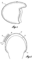
- the embodiments provided herein include an impact diverting mechanism 16, which can optionally be added as a protective add-on to a helmet 10 or other equipment for protection (e.g., for protection of a wearer's head or body from injuries).
- a typical helmet 10, as known in the prior art, is illustrated in FIGURE 1 .
- the mechanism 16 is illustrated as attached to a helmet 10 in FIGURE 2 .
- the mechanism 16 comprises a bottom layer 18 that is mechanically attached to a top layer 22 disposed above the bottom layer 18.
- the top layer 22 protects the bottom layer 18 by reducing rotational acceleration when the mechanism is impacted at an oblique angle.
- the bottom layer 18 is attached to an outer shell 12 of the helmet 10 in the illustrated representative embodiment.
- the bottom layer is the layer closest to the object and a top layer is the layer distal to the object.
- the bottom layer 18 is fixedly or otherwise solidly attached to the surface 12 of the outer shell by means of an adhesive or mechanical fastening as shown in FIGURES 2 .
- the bottom layer 18 is made from thermosetting plastics (e.g., silicone), conventional thermoplastic, thermoset elastomers such as polyurethane elastomers, natural or synthetic rubbers, plasticized foams, or low- or high-density polyethylene.
- the bottom layer 18 can be a plain layer, a composite layer, or a layer comprising chambers. If chambers are included, the chambers contain dilatant (shear thickening) material (viscosity increases with the rate of shear strain) such as d3oTM or the like, that reduces the linear acceleration applied by an impact load on the protective equipment. In certain embodiments, other shock absorbing materials or mechanisms are used to reduce linear acceleration even further.
- the top layer 22a is a plain layer (i.e., nothing is added to the polymer to make it a composite) of flexible and stretchable material(s) such as thermosetting plastics (e.g., silicone), conventional thermoplastic, thermoset elastomers such as polyurethane elastomers, natural or synthetic rubbers, plasticized foams, or low- or high-density polyethylene.
- thermosetting plastics e.g., silicone
- thermoset elastomers such as polyurethane elastomers, natural or synthetic rubbers, plasticized foams, or low- or high-density polyethylene.
- the top layer and the bottom layer are made of elastic or inelastic materials, such as thermosetting plastics, conventional thermoplastics, or thermoset elastomers.
- the top layer top layer 22 is arranged to be placed over an optional intermediate layer 20, which is disposed between the top 22 and bottom 18 layers.
- the intermediate layer 20 is an independent layer, but in certain embodiments the top and/or bottom layer is self-lubricating in order to facilitate movement between the layers.
- there is lubrication between the top layer and the bottom layer selected from the group consisting of self-lubrication on the top layer, self-lubrication on the bottom layer, an independent lubricant between the top layer and the bottom layer, and combinations thereof.
- the intermediate layer 20 is a lubricating material or gel able to facilitate relative motion between the top layer 22 and the bottom layer 18. Separation of lubricating material from the hard shell 12 is to avoid possible deterioration of the hard outer shell 12 over a long period, and this embodiment can be used for any type of hard shell 12.
- the top layer 22 and the bottom layer 18 may abut or may be separated by a gap, while still being mechanically connected.
- the mechanism 16 can be applied to cover an outer surface of any kind of protective equipment (e.g., personal protective equipment) as a whole layer or as a cover that consists of a number of compartments in different shapes, placed in a random or uniform pattern connected or not connected to each other.
- any kind of protective equipment e.g., personal protective equipment
- the layers of the mechanism 16 are configured such that during an oblique impact, the top layer 22 goes through temporary or permanent deformation or ruptures and moves relative (e.g., laterally) to the bottom layer 18 to reduce rotational acceleration. Accordingly, in one embodiment, the bottom layer and the top layer are configured such that the top layer shifts substantially laterally relative to the bottom layer as a result of the oblique impact force acting on the top layer. As used herein, the term "substantially laterally” describes movement that is greater in the tangential direction than in the perpendicular direction, as illustrated in FIGURE 9 .
- the top layer ruptures or is permanently deformed when impacted.
- the representative embodiments described herein typically include an object (e.g., a helmet), onto which the impact diverting mechanism is mounted or otherwise attached.
- the impact diverting mechanism is not mounted to an object. Instead, the impact diverting mechanism can be configured to attach to an object in need of protection.
- the bottom layer is configured to be fixedly attached to the surface of an object, and wherein the impact diverting mechanism is configured to reduce rotational acceleration of the object when exposed to the oblique impact force compared to the rotational acceleration of the object without the impact diverting mechanism when exposed to the oblique impact force.
- the bottom layer is attached to the object using an adhesive, co-molding, mechanical means, a peel-and-stick material, or any other method of attachment.
- adhesives are well known to those of skill in the art.
- the bottom layer is attached to the object, and wherein the object is the outer layer of a protective gear or armor, and wherein the attachment is at one or more locations using an adhesive or mechanical means.
- the outer surface of the top layer has a surface selected from the group consisting of smooth, flat, and a texture for a better mechanical grip during the oblique impact force.
- the top layer 22 is an armored layer 22b (e.g., a composite layer comprising a polymer and an additive) comprising a small flat discs 28 made from a flexible and stretchable material(s).
- a procedure of making the armored layer 22b is making a flexible thin layer first, then placing the small flat discs 28 on the first layer, and then adding a second layer of flexible material on the top. After curing, the top layer 22b is one united layer with the flat small discs 28 spreading in between the layer 22b (e.g., similar to fish scales).
- the outer surface of the top layer employs a texture to increase the grip between the top layer and the impact area resulting in a better performance of the top and bottom layer.
- the top layer 22 contains particles with relatively high stiffness (e.g., embedded as a composite in the top layer 22). Such particles reinforce the layer 22 against impact load and/or improve the sliding ability of the top layer 22 on the lubricant 20 and the bottom layer 18. On the other hand, existence of the particles does not increase the general stiffness of the layer 22, as the particles are separate and allow the elastic top layer 22 to keep its flexibility and stretchability. This type of layer can significantly reduce the rotational acceleration and also is more resilient to work on rough surfaces.
- one or more additional layers are added on the top layer, including one or more lubricated layers and reinforced layers free to move relative to each other.
- a diverting mechanism comprises a casing layer 30 for a number of small balls 32 wherein the individual balls 32 are in their casings 30 and are free to rotate, as illustrated in FIGURES 6A and 6B .
- the elastic layer contains small the rigid casings that balls can freely rotate inside. Therefore, there is no lubrication layer as in other designs provided herein. Also, lubrication might be used inside casing to improve the rotations of the balls. During an oblique impact, the rotation of these small balls 32 in their casings 30 allows the helmet 10 to slide instead of roll, thus decreasing the rotational acceleration.
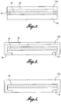
- the top layer 22 is attached to the bottom layer 18 by different methods as shown in FIGURES 3, 4, 5 , 7 and 8 .
- the top layer 22b which comprises small flat discs 28, and the bottom layer 18, are attached to each other by an attachment edge 24 (i.e., a tongue and groove are designed for the two layers for attachment).
- the top layer is attached to the bottom layer around the perimeter.
- the two layers are connected throughout a portion of their adjacent surfaces but not throughout their entire adjacent surfaces.
- the top layer 22 comprises extended edges 26 extending outwardly in order to be folded underneath the bottom layer 18 as shown in FIGURES 4, 5 , 7 and 8 .
- extended edges 26 can create an "edgeless" design so as to allow for fewer sharp edges on the helmet and to improve aesthetics.
- the edgeless design if 'the impact applies to the perimeter of the impact diverting mechanism 16, the mechanism is still functional and the helmet 10 can slide on. The difference between edgeless design and designs with inactive edges can be observed better if a protective layer needs to be installed on the helmet with no access to the helmet's actual perimeter edges to hide.
- the edgeless design can be created only by using two layers. Using the edgeless design, if the impact applies to the perimeter of the impact diverting mechanism, it is still functional and the helmet can slide on. Using only one layer, attaching the boundary of the outer layer to the hard shell can create inactive edges. Hitting the inactive edges of the outer layer does may not reduce rotational acceleration as effectively as the edgeless design. The difference between edgeless design and designs with inactive edges can be observed better if a protective layer needs to be installed on the helmet with no access to the helmet actual perimeter edges to hide.
- FIGURE 7 a top view of a top layer 22 of an impact diverting mechanism 16 with a plurality of extended edges 26 is illustrated, in accordance with the embodiments provided herein.
- the extended edges 26 are shaped as tabs that can then be folded under an overhanging edge (e.g., margin area 34 in FIGURE 8 ) of the bottom layer 18, as illustrated in FIGURES 4 and 5 , or under an edge of the helmet 10 upon which the mechanism 16 is mounted.
- FIGURE 8 a top view of a bottom layer 18 with a margin area 34 for placing the extended edge 26 of the top layer from FIGURE 7 underneath it in accordance with the embodiments provided herein.
- top and bottom layers are one whole part without any attaching borders.
- the mechanism 16 reduces rotational acceleration during an oblique impact and will provide extra safety to the wearer of such a helmet 10.
- the layers of the mechanism 16 can be created from shock-absorbing materials such as shear thickening (dilatant) materials to not only protect against rotational acceleration but also mitigate linear acceleration experienced by the wearer's head and body.
- Some of the benefits of having both a top layer 22 and a bottom layer 18 (separated by a lubricant 20) compared to a single layer protection mechanism, include:
- the mechanism includes a gap between the top layer and the bottom layer.
- the bottom layer is attached to the object, and wherein the object is a vehicle, aircraft, or other object exposed to an oblique impact force.
- the bottom layer is attached to an interior of the object.
- the object is the passenger compartment of an airplane, automobile, train, or other vessel exposed to an oblique impact force.
- the outer surface of the top layer has illuminating materials or devices embedded to improve its visibility in low light conditions.
- the outer surface of the first or top layer is configured to display information.
- the information is an advertisement, logo, trademark, certification label, warning label, serial number, or the like.
- the impact diverting mechanism reduces linear acceleration of the object when exposed to the oblique impact force, compared to the linear acceleration of the object without the impact diverting mechanism when exposed to the oblique impact force.
- the top layer is configured to attach to the object as well as to the bottom layer.
- any of the layers is an integral part of any other layer.
- any of the layers is independent of any other layer.
- the top layer includes particles with relatively high stiffness that improves the ability of the top layer to shift relative to the bottom layer.
- the impact diverting mechanism is configured to reduce linear acceleration of the bottom layer relative to the top layer.
- the bottom layer is a plain layer, a composite layer, or a layer comprising chambers.
- the top layer or the bottom layer comprises a laminate structure.
Applications Claiming Priority (3)
| Application Number | Priority Date | Filing Date | Title |
|---|---|---|---|
| US201161503054P | 2011-06-30 | 2011-06-30 | |
| EP12805056.4A EP2725936B1 (en) | 2011-06-30 | 2012-06-29 | Impact diverting mechanism |
| PCT/CA2012/050449 WO2013000095A1 (en) | 2011-06-30 | 2012-06-29 | Impact diverting mechanism |
Related Parent Applications (1)
| Application Number | Title | Priority Date | Filing Date |
|---|---|---|---|
| EP12805056.4A Division EP2725936B1 (en) | 2011-06-30 | 2012-06-29 | Impact diverting mechanism |
Publications (1)
| Publication Number | Publication Date |
|---|---|
| EP3673757A1 true EP3673757A1 (en) | 2020-07-01 |
Family
ID=47423341
Family Applications (2)
| Application Number | Title | Priority Date | Filing Date |
|---|---|---|---|
| EP20155941.6A Pending EP3673757A1 (en) | 2011-06-30 | 2012-06-29 | Impact diverting mechanism |
| EP12805056.4A Active EP2725936B1 (en) | 2011-06-30 | 2012-06-29 | Impact diverting mechanism |
Family Applications After (1)
| Application Number | Title | Priority Date | Filing Date |
|---|---|---|---|
| EP12805056.4A Active EP2725936B1 (en) | 2011-06-30 | 2012-06-29 | Impact diverting mechanism |
Country Status (9)
| Country | Link |
|---|---|
| US (2) | US9232824B2 (pl) |
| EP (2) | EP3673757A1 (pl) |
| JP (5) | JP2014518337A (pl) |
| AU (1) | AU2012276224B2 (pl) |
| CA (2) | CA3014872C (pl) |
| DK (1) | DK2725936T3 (pl) |
| ES (1) | ES2791752T3 (pl) |
| PL (1) | PL2725936T3 (pl) |
| WO (1) | WO2013000095A1 (pl) |
Families Citing this family (37)
| Publication number | Priority date | Publication date | Assignee | Title |
|---|---|---|---|---|
| JP2014518337A (ja) | 2011-06-30 | 2014-07-28 | サイモン フレーザー 大学 | 衝撃迂回機構 |
| US9763488B2 (en) | 2011-09-09 | 2017-09-19 | Riddell, Inc. | Protective sports helmet |
| US10159296B2 (en) | 2013-01-18 | 2018-12-25 | Riddell, Inc. | System and method for custom forming a protective helmet for a customer's head |
| US10813401B2 (en) | 2013-07-31 | 2020-10-27 | Zymplr LC | Headband to reduce concussions and traumatic brain injuries |
| US9839251B2 (en) * | 2013-07-31 | 2017-12-12 | Zymplr LC | Football helmet liner to reduce concussions and traumatic brain injuries |
| WO2015047033A1 (en) | 2013-09-30 | 2015-04-02 | Samsung Electronics Co., Ltd. | System and method for providing cloud printing service |
| EP3048918A4 (en) | 2013-12-06 | 2017-06-14 | Bell Sports, Inc. | Flexible multi-layer helmet and method for making the same |
| CA3186442A1 (en) * | 2013-12-19 | 2015-06-25 | Bauer Hockey Ltd. | Helmet for impact protection |
| CA3207551A1 (en) | 2014-10-28 | 2016-05-06 | Bell Sports, Inc. | In-mold rotation helmet |
| USD773742S1 (en) | 2015-03-10 | 2016-12-06 | Albert Williams | Helmet |
| US10092054B2 (en) | 2015-03-10 | 2018-10-09 | Albert Williams | Helmets or other protective headgear and related methods |
| ITUB20152289A1 (it) * | 2015-07-17 | 2017-01-17 | Anomaly Action Sports S R L | Casco di protezione. |
| EP3357364B1 (en) * | 2015-07-17 | 2024-05-15 | Anomaly Action Sports S.r.l. | Protective helmet |
| US9961952B2 (en) | 2015-08-17 | 2018-05-08 | Bauer Hockey, Llc | Helmet for impact protection |
| US10463099B2 (en) * | 2015-12-11 | 2019-11-05 | Bell Sports, Inc. | Protective helmet with multiple energy management liners |
| US10433609B2 (en) | 2016-01-08 | 2019-10-08 | VICIS, Inc. | Layered materials and structures for enhanced impact absorption |
| US10470513B2 (en) * | 2016-03-01 | 2019-11-12 | Mips Ab | Helmet |
| GB201603566D0 (en) | 2016-03-01 | 2016-04-13 | Mips Ab | Helmet |
| CA3018579A1 (en) | 2016-03-23 | 2017-09-28 | Simon Fraser University | Modular disengaging system |
| WO2017192885A2 (en) * | 2016-05-06 | 2017-11-09 | Walterspiel Juan N | Shock absorbing system |
| WO2018017867A1 (en) | 2016-07-20 | 2018-01-25 | Riddell, Inc. | System and methods for designing and manufacturing a bespoke protective sports helmet |
| GB201621272D0 (en) | 2016-12-14 | 2017-01-25 | Mips Ab | Helmet |
| JP2020063520A (ja) * | 2017-02-14 | 2020-04-23 | 株式会社クラフト | 柔らかい外殻に覆われたヘルメット |
| CN110621495A (zh) * | 2017-03-06 | 2019-12-27 | 西蒙弗雷泽大学 | 缓冲膜 |
| CN111511239B (zh) * | 2017-10-19 | 2023-03-28 | 米帕斯公司 | 头盔 |
| US11238982B2 (en) | 2018-01-11 | 2022-02-01 | International Business Machines Corporation | Managing medical events using visual patterns generated from multivariate medical records |
| US11399589B2 (en) | 2018-08-16 | 2022-08-02 | Riddell, Inc. | System and method for designing and manufacturing a protective helmet tailored to a selected group of helmet wearers |
| WO2020107005A1 (en) | 2018-11-21 | 2020-05-28 | Riddell, Inc. | Protective recreational sports helmet with components additively manufactured to manage impact forces |
| USD927084S1 (en) | 2018-11-22 | 2021-08-03 | Riddell, Inc. | Pad member of an internal padding assembly of a protective sports helmet |
| US11766083B2 (en) | 2019-03-25 | 2023-09-26 | Tianqi Technology Co (Ningbo) Ltd | Helmet |
| GB201908090D0 (en) * | 2019-06-06 | 2019-07-24 | Hexr Ltd | Helmet |
| CN116261408A (zh) * | 2020-09-18 | 2023-06-13 | Hexr有限公司 | 缓和冲击结构 |
| USD995924S1 (en) | 2021-03-17 | 2023-08-15 | Studson, Inc. | Protective helmet |
| USD995925S1 (en) | 2020-09-23 | 2023-08-15 | Studson, Inc. | Protective helmet |
| USD1004850S1 (en) | 2021-03-17 | 2023-11-14 | Studson, Inc. | Protective helmet |
| WO2022066857A1 (en) * | 2020-09-24 | 2022-03-31 | Kuji Sports Co Ltd | Helmet |
| CA3224968A1 (en) * | 2021-07-13 | 2023-01-19 | Robin Spicer | Functional reactive layer helmet |
Citations (6)
| Publication number | Priority date | Publication date | Assignee | Title |
|---|---|---|---|---|
| US4307471A (en) * | 1976-12-20 | 1981-12-29 | Du Pont Canada Inc. | Protective helmet |
| WO2003005844A1 (en) | 2001-07-09 | 2003-01-23 | Phillips Helmets Limited | Protective headgear and protective armour and a method of modifying protective headgear and protective armour |
| US20040117896A1 (en) * | 2002-10-04 | 2004-06-24 | Madey Steven M. | Load diversion method and apparatus for head protective devices |
| WO2006091947A2 (en) * | 2005-02-25 | 2006-08-31 | The Aerospace Corporation | Force diversion apparatus and methods and devices including the same |
| WO2009019667A1 (en) | 2007-08-09 | 2009-02-12 | Profilo Design S.R.L. | Coating for helmet and respective helmet |
| WO2010151631A1 (en) | 2009-06-25 | 2010-12-29 | Wayne State University | Omni-directional angular acceration reduction for protective headgear |
Family Cites Families (22)
| Publication number | Priority date | Publication date | Assignee | Title |
|---|---|---|---|---|
| US4012794A (en) * | 1975-08-13 | 1977-03-22 | Tetsuo Nomiyama | Impact-absorbing helmet |
| GB9423113D0 (en) | 1994-11-16 | 1995-01-04 | Phillips Kenneth D | Protective headgear |
| JPH09143814A (ja) * | 1995-11-24 | 1997-06-03 | Taisou:Kk | ヘルメット |
| WO1998057222A1 (en) * | 1997-06-10 | 1998-12-17 | Lg. Philips Lcd Co., Ltd. | Liquid crystal display with wide viewing angle and method for making it |
| JP2000303243A (ja) * | 1999-04-15 | 2000-10-31 | Sumitomo Bakelite Co Ltd | 耐衝撃性ヘルメット |
| JP4399909B2 (ja) * | 1999-08-09 | 2010-01-20 | 住友ベークライト株式会社 | 耐衝撃性ヘルメット |
| ATE271325T1 (de) * | 1999-12-21 | 2004-08-15 | Neuroprevention Scandinavia Ab | Schutzhelm |
| JP3765377B2 (ja) * | 2000-04-04 | 2006-04-12 | 本田技研工業株式会社 | ヘルメット |
| US6282724B1 (en) | 2001-02-21 | 2001-09-04 | Carl Joel Abraham | Apparatus for enhancing absorption and dissipation of impact forces for all helmets and protective equipment |
| US8388164B2 (en) * | 2005-05-17 | 2013-03-05 | Michael Waters | Hands-Free lighting devices |
| US20040250340A1 (en) * | 2003-02-05 | 2004-12-16 | Dennis Piper | Protective headguard |
| DE20313629U1 (de) * | 2003-09-03 | 2003-12-24 | Stehn, Hartwig | Sicherheitsleuchteinrichtung für Helme |
| US20060059606A1 (en) | 2004-09-22 | 2006-03-23 | Xenith Athletics, Inc. | Multilayer air-cushion shell with energy-absorbing layer for use in the construction of protective headgear |
| JP2006016740A (ja) | 2004-07-05 | 2006-01-19 | Honda Motor Co Ltd | ヘルメット |
| US7461726B2 (en) * | 2005-02-25 | 2008-12-09 | The Aerospace Corporation | Force diversion apparatus and methods |
| CN101557731B (zh) * | 2006-10-13 | 2013-04-03 | 英属哥伦比亚大学 | 用于减轻脊髓损伤的设备 |
| US8087101B2 (en) * | 2007-01-19 | 2012-01-03 | James Riddell Ferguson | Impact shock absorbing material |
| SE536246C2 (sv) * | 2010-01-13 | 2013-07-16 | Mips Ab | Mellanliggande lager av friktionsminskande material |
| SE534868C2 (sv) * | 2010-05-07 | 2012-01-24 | Mips Ab | Hjälm med glidningsfrämjare anordnad vid ett energiabsorberande lager |
| US20120208032A1 (en) * | 2011-02-14 | 2012-08-16 | Kinetica Inc. | Helmet designs utilizing an outer slip layer |
| JP2014518337A (ja) | 2011-06-30 | 2014-07-28 | サイモン フレーザー 大学 | 衝撃迂回機構 |
| US9089180B2 (en) * | 2011-09-08 | 2015-07-28 | Emerson Spalding Phipps | Protective helmet |
-
2012
- 2012-06-29 JP JP2014517359A patent/JP2014518337A/ja active Pending
- 2012-06-29 EP EP20155941.6A patent/EP3673757A1/en active Pending
- 2012-06-29 CA CA3014872A patent/CA3014872C/en active Active
- 2012-06-29 WO PCT/CA2012/050449 patent/WO2013000095A1/en active Application Filing
- 2012-06-29 PL PL12805056T patent/PL2725936T3/pl unknown
- 2012-06-29 DK DK12805056.4T patent/DK2725936T3/da active
- 2012-06-29 US US14/130,257 patent/US9232824B2/en active Active
- 2012-06-29 ES ES12805056T patent/ES2791752T3/es active Active
- 2012-06-29 AU AU2012276224A patent/AU2012276224B2/en active Active
- 2012-06-29 EP EP12805056.4A patent/EP2725936B1/en active Active
- 2012-06-29 CA CA2874768A patent/CA2874768C/en active Active
-
2016
- 2016-01-11 US US14/992,749 patent/US10143255B2/en active Active
- 2016-12-12 JP JP2016240161A patent/JP6386012B2/ja active Active
-
2018
- 2018-08-08 JP JP2018148974A patent/JP7061535B2/ja active Active
-
2020
- 2020-07-03 JP JP2020115274A patent/JP2020183609A/ja active Pending
-
2022
- 2022-11-08 JP JP2022179157A patent/JP2023011901A/ja active Pending
Patent Citations (6)
| Publication number | Priority date | Publication date | Assignee | Title |
|---|---|---|---|---|
| US4307471A (en) * | 1976-12-20 | 1981-12-29 | Du Pont Canada Inc. | Protective helmet |
| WO2003005844A1 (en) | 2001-07-09 | 2003-01-23 | Phillips Helmets Limited | Protective headgear and protective armour and a method of modifying protective headgear and protective armour |
| US20040117896A1 (en) * | 2002-10-04 | 2004-06-24 | Madey Steven M. | Load diversion method and apparatus for head protective devices |
| WO2006091947A2 (en) * | 2005-02-25 | 2006-08-31 | The Aerospace Corporation | Force diversion apparatus and methods and devices including the same |
| WO2009019667A1 (en) | 2007-08-09 | 2009-02-12 | Profilo Design S.R.L. | Coating for helmet and respective helmet |
| WO2010151631A1 (en) | 2009-06-25 | 2010-12-29 | Wayne State University | Omni-directional angular acceration reduction for protective headgear |
Also Published As
| Publication number | Publication date |
|---|---|
| PL2725936T3 (pl) | 2020-10-05 |
| JP2018197420A (ja) | 2018-12-13 |
| JP2020183609A (ja) | 2020-11-12 |
| CA2874768A1 (en) | 2013-01-03 |
| CA2874768C (en) | 2018-10-02 |
| EP2725936B1 (en) | 2020-02-12 |
| EP2725936A4 (en) | 2015-04-29 |
| US20140189945A1 (en) | 2014-07-10 |
| ES2791752T3 (es) | 2020-11-05 |
| US20160120256A1 (en) | 2016-05-05 |
| CA3014872C (en) | 2021-06-08 |
| EP2725936A1 (en) | 2014-05-07 |
| DK2725936T3 (da) | 2020-05-18 |
| AU2012276224B2 (en) | 2016-08-11 |
| CA3014872A1 (en) | 2013-01-03 |
| WO2013000095A1 (en) | 2013-01-03 |
| JP2023011901A (ja) | 2023-01-24 |
| JP7061535B2 (ja) | 2022-04-28 |
| US9232824B2 (en) | 2016-01-12 |
| JP2017082384A (ja) | 2017-05-18 |
| AU2012276224A1 (en) | 2014-01-16 |
| JP2014518337A (ja) | 2014-07-28 |
| JP6386012B2 (ja) | 2018-09-05 |
| US10143255B2 (en) | 2018-12-04 |
Similar Documents
| Publication | Publication Date | Title |
|---|---|---|
| EP2725936B1 (en) | Impact diverting mechanism | |
| AU2002317312B2 (en) | Protective headgear and protective armour and a method of modifying protective headgear and protective armour | |
| EP2802229B1 (en) | Head protection for reducing angular accelerations | |
| US20160316845A1 (en) | Helmet with sliding facilitator arranged at energy absorbing layer | |
| AU2002317312A1 (en) | Protective headgear and protective armour and a method of modifying protective headgear and protective armour | |
| CN110913714A (zh) | 头盔 | |
| CN107205515A (zh) | 内成型转动头盔 | |
| EP3307062B1 (en) | Ecostructural bicycle/activity safety helmet | |
| US20140101829A1 (en) | Protective helmet configuration with integrated face mask with smooth transition attachment | |
| US11589630B2 (en) | Protective device | |
| EP3986193B1 (en) | Protective helmet | |
| WO2022241557A1 (en) | Helmet sheer layer | |
| CN117396099A (zh) | 头盔 | |
| CN117377406A (zh) | 壳体、套件、头盔和制造壳体的方法 |
Legal Events
| Date | Code | Title | Description |
|---|---|---|---|
| PUAI | Public reference made under article 153(3) epc to a published international application that has entered the european phase |
Free format text: ORIGINAL CODE: 0009012 |
|
| STAA | Information on the status of an ep patent application or granted ep patent |
Free format text: STATUS: REQUEST FOR EXAMINATION WAS MADE |
|
| 17P | Request for examination filed |
Effective date: 20200206 |
|
| AC | Divisional application: reference to earlier application |
Ref document number: 2725936 Country of ref document: EP Kind code of ref document: P |
|
| AK | Designated contracting states |
Kind code of ref document: A1 Designated state(s): AL AT BE BG CH CY CZ DE DK EE ES FI FR GB GR HR HU IE IS IT LI LT LU LV MC MK MT NL NO PL PT RO RS SE SI SK SM TR |
|
| RIN1 | Information on inventor provided before grant (corrected) |
Inventor name: WANG, GAOFENG GARY Inventor name: GOLNARAGHI, FARID Inventor name: EAMON ABRAM, DANIEL Inventor name: JELVEH, COMBIZ |
|
| STAA | Information on the status of an ep patent application or granted ep patent |
Free format text: STATUS: EXAMINATION IS IN PROGRESS |
|
| 17Q | First examination report despatched |
Effective date: 20210810 |
|
| P01 | Opt-out of the competence of the unified patent court (upc) registered |
Effective date: 20230526 |