EP3673730A1 - Dual auger internal clean-in-place bearing - Google Patents
Dual auger internal clean-in-place bearing Download PDFInfo
- Publication number
- EP3673730A1 EP3673730A1 EP19216656.9A EP19216656A EP3673730A1 EP 3673730 A1 EP3673730 A1 EP 3673730A1 EP 19216656 A EP19216656 A EP 19216656A EP 3673730 A1 EP3673730 A1 EP 3673730A1
- Authority
- EP
- European Patent Office
- Prior art keywords
- auger
- shaft
- bearing
- assembly
- housing
- Prior art date
- Legal status (The legal status is an assumption and is not a legal conclusion. Google has not performed a legal analysis and makes no representation as to the accuracy of the status listed.)
- Granted
Links
Images




Classifications
-
- A—HUMAN NECESSITIES
- A01—AGRICULTURE; FORESTRY; ANIMAL HUSBANDRY; HUNTING; TRAPPING; FISHING
- A01J—MANUFACTURE OF DAIRY PRODUCTS
- A01J25/00—Cheese-making
- A01J25/008—Apparatus for making soft uncured Italian cheese, e.g. Mozzarella, Ricotta, Pasta Filata cheese
-
- A—HUMAN NECESSITIES
- A01—AGRICULTURE; FORESTRY; ANIMAL HUSBANDRY; HUNTING; TRAPPING; FISHING
- A01J—MANUFACTURE OF DAIRY PRODUCTS
- A01J25/00—Cheese-making
- A01J25/002—Cheese-making continuously
-
- A—HUMAN NECESSITIES
- A01—AGRICULTURE; FORESTRY; ANIMAL HUSBANDRY; HUNTING; TRAPPING; FISHING
- A01J—MANUFACTURE OF DAIRY PRODUCTS
- A01J25/00—Cheese-making
- A01J25/11—Separating whey from curds; Washing the curds
- A01J25/111—Separating whey from curds; Washing the curds by continuous separation
- A01J25/112—Separating whey from curds; Washing the curds by continuous separation in cylinders
-
- A—HUMAN NECESSITIES
- A01—AGRICULTURE; FORESTRY; ANIMAL HUSBANDRY; HUNTING; TRAPPING; FISHING
- A01J—MANUFACTURE OF DAIRY PRODUCTS
- A01J25/00—Cheese-making
- A01J25/12—Forming the cheese
- A01J25/126—Cleaning cheese making equipment
-
- A—HUMAN NECESSITIES
- A23—FOODS OR FOODSTUFFS; TREATMENT THEREOF, NOT COVERED BY OTHER CLASSES
- A23C—DAIRY PRODUCTS, e.g. MILK, BUTTER OR CHEESE; MILK OR CHEESE SUBSTITUTES; PREPARATION THEREOF
- A23C19/00—Cheese; Cheese preparations; Making thereof
- A23C19/06—Treating cheese curd after whey separation; Products obtained thereby
- A23C19/068—Particular types of cheese
- A23C19/08—Process cheese preparations; Making thereof, e.g. melting, emulsifying, sterilizing
- A23C19/084—Treating the curd, or adding substances thereto, after melting
-
- B—PERFORMING OPERATIONS; TRANSPORTING
- B65—CONVEYING; PACKING; STORING; HANDLING THIN OR FILAMENTARY MATERIAL
- B65G—TRANSPORT OR STORAGE DEVICES, e.g. CONVEYORS FOR LOADING OR TIPPING, SHOP CONVEYOR SYSTEMS OR PNEUMATIC TUBE CONVEYORS
- B65G33/00—Screw or rotary spiral conveyors
- B65G33/08—Screw or rotary spiral conveyors for fluent solid materials
- B65G33/14—Screw or rotary spiral conveyors for fluent solid materials comprising a screw or screws enclosed in a tubular housing
- B65G33/18—Screw or rotary spiral conveyors for fluent solid materials comprising a screw or screws enclosed in a tubular housing with multiple screws in parallel arrangements, e.g. concentric
-
- B—PERFORMING OPERATIONS; TRANSPORTING
- B65—CONVEYING; PACKING; STORING; HANDLING THIN OR FILAMENTARY MATERIAL
- B65G—TRANSPORT OR STORAGE DEVICES, e.g. CONVEYORS FOR LOADING OR TIPPING, SHOP CONVEYOR SYSTEMS OR PNEUMATIC TUBE CONVEYORS
- B65G33/00—Screw or rotary spiral conveyors
- B65G33/24—Details
- B65G33/32—Adaptations of bearings or couplings for supporting and connecting screws
-
- B—PERFORMING OPERATIONS; TRANSPORTING
- B65—CONVEYING; PACKING; STORING; HANDLING THIN OR FILAMENTARY MATERIAL
- B65G—TRANSPORT OR STORAGE DEVICES, e.g. CONVEYORS FOR LOADING OR TIPPING, SHOP CONVEYOR SYSTEMS OR PNEUMATIC TUBE CONVEYORS
- B65G45/00—Lubricating, cleaning, or clearing devices
- B65G45/005—Cleaning conveyor screws
-
- A—HUMAN NECESSITIES
- A01—AGRICULTURE; FORESTRY; ANIMAL HUSBANDRY; HUNTING; TRAPPING; FISHING
- A01J—MANUFACTURE OF DAIRY PRODUCTS
- A01J25/00—Cheese-making
- A01J25/12—Forming the cheese
-
- B—PERFORMING OPERATIONS; TRANSPORTING
- B01—PHYSICAL OR CHEMICAL PROCESSES OR APPARATUS IN GENERAL
- B01F—MIXING, e.g. DISSOLVING, EMULSIFYING OR DISPERSING
- B01F2101/00—Mixing characterised by the nature of the mixed materials or by the application field
- B01F2101/06—Mixing of food ingredients
- B01F2101/11—Mixing of cheese ingredients
Definitions
- the invention relates to a method and assembly for receiving and conveying particles of cheese curd downstream along a cheese processing line, where augers are used to receive and convey the cheese particles.
- a production process for producing cheddar cheese may include cheddaring, milling, and salting of particles of cheese curd. Salting the cheese curd advantageously causes more moisture to be expelled from the curd.
- the production process for a producing cheddar cheese may include using a cheddaring machine that includes a plurality of conveyors. A first conveyor is configured to receive a curd mixture that has been drained of whey. The curd then travels downstream to additional conveyors for matting, fusing, and cheddaring. The curd is then moved further downstream where the curd is milled to chips or stirred depending on the type of cheese to be produced. For example, producing a Colby type of cheese may require stirred curd. The curd may then be salted while being conveyed to a final conveyor for mellowing.
- the conveyors of the cheddaring machine used during the draining, salting, and/or mellowing processes may be auger-type conveyors. Cleaning the augers is generally performed using a plurality of spray nozzles that randomly spray along the auger.
- conventional spray nozzles used to clean the augers may not be suitable for thoroughly cleaning and sanitizing all of the components of the auger, particularly in narrow regions where auger bearings and other components are located.
- Conventional spray nozzles are disadvantageous in that the augers may require manual disassembly and removal of the components for cleaning, which is also known as a clean out of place (COP) system.
- COP clean out of place
- CIP clean-in-place
- an auger assembly is used for receiving particles of cheese curd and conveying the particles of cheese curd downstream along a cheese processing line.
- the auger assembly includes an auger housing, a first auger having a first shaft extending through the auger housing, a second auger having a second shaft extending through the auger housing and arranged colinearly with the first shaft, a first bearing mounted to the auger housing and arranged at the end of the first shaft, and a second bearing mounted to the auger housing and arranged at the end of the second shaft.
- the second shaft has an end that faces an end of the first shaft, and the first bearing and second bearing are colinear and face each other. At least one slotted groove is formed in each of the first bearing and the second bearing to enable a cleaning fluid to contact a surface of the respective bearing.
- the auger assembly described herein is advantageous in enabling a CIP system which directs cleaning fluid to the bearings of the shafts.
- the CIP fluid is introduced down the rotatable shafts of each auger to flood the area where the bearings are located with the CIP fluid.
- the bearings are connected to the shafts with a slip fit connection and the slotted grooves enable the CIP fluid to travel down the shafts through the grooves to cover the area where the connection between the bearings and the shafts is formed.
- COP clean out of place
- a method for operating an auger assembly arranged to rotate a first auger and a second auger to convey cheese curd downstream along a cheese processing line includes supplying particles of cheese curd to the first auger and the second auger that are colinearly arranged, driving a first shaft of the first auger and a second shaft of the second auger, expelling the particles of cheese curd through outlets at an end of the first auger and at an end of the second auger to convey the particles of cheese curd downstream along the cheese processing line, and supplying a cleaning fluid directly to bearings in the first and second auger that are arranged for mounting the first and second shaft within an auger housing.
- the method and system according to the present invention has particular application in a cheese processing line that uses conveyors, such as auger-type conveyors for receiving particles of cheese curd and conveying the particles of cheese curd downstream along a cheese processing line.
- Augers may be used at various stages along a cheese processing line configured for producing a cheddar type of cheese.
- augers may be used to convey the cheese curd during the draining, salting, and/or mellowing stages of cheese production.
- Other types of cheese production lines may also use augers for producing types of cheeses other than cheddar.
- the method and assembly use an auger assembly for receiving particles of cheese curd and conveying the particles of cheese curd downstream along a cheese processing line.
- the auger assembly includes an auger housing, a first auger having a first shaft extending through the auger housing, a second auger having a second shaft extending through the auger housing and arranged colinearly with the first shaft, a first bearing mounted to the auger housing and arranged at the end of the first shaft, and a second bearing mounted to the auger housing and arranged at the end of the second shaft.
- the second shaft has an end that faces an end of the first shaft, and the first bearing and second bearing are colinear and facing each other.
- a slotted groove is formed in each of the bearings to enable a clean in place (CIP) fluid to contact surfaces of the bearings, such that cleaning of the bearings is ensured.
- the slotted grooves may extend through an entire longitudinal length of the bearings to enable the CIP fluid to travel along the auger shafts by way of the grooves and across the area where the bearings are connected with the shafts.
- the bearings are also removably mounted to a housing of the auger assembly using a mounting bracket which also supports the CIP fluid line to direct the CIP fluid to the slotted grooves.
- the bearings are easily replaceable within the auger assembly.
- Using the bearings and CIP system enables cleaning during normal operation of the auger assembly which subsequently improves the life of the bearings and is less burdensome than the conventionally used clean out of place (COP) system in which the auger is manually disassembled for cleaning the bearings.
- COP clean out of place
- the auger assembly 1 includes an auger housing 2 that is configured to surround and support a first auger 3 and a second auger 4, such that the auger assembly 1 may be a dual auger assembly. In particular applications, only one auger may be provided or more than two augers may be provided.
- the first auger 3 has a first shaft 5 and the second auger 4 has a second shaft 6.
- the first shaft 5 and the second shaft 6 each extend through the auger housing 2.
- the auger housing 2 may have any suitable shape, and the auger housing 2 may be at least partially cylindrical in shape such that the cylindrical portion of the housing 2 surrounds the shafts 5, 6.
- the first shaft 5 and the second shaft 6 are colinearly arranged and rotatable about a common longitudinal axis L.
- the first shaft 5 has an end 7 that faces an end 8 of the second shaft 6.
- the end 7 and the end 8 may be axially spaced from each other by a predetermined distance D 1 such that the first shaft 5 and the second shaft 6 are also axially spaced by the predetermined distance D 1 , which may be any suitable distance.
- the predetermined distance D 1 may be between 0.51 centimeters (0.20 inches) and 0.76 centimeters (0.30 inches). Spacing the first shaft 5 and the second shaft 6 relative to each other enables the first auger 3 and the second auger 4 to operate independently from each other. Independent operation of the augers 3, 4 enables travel of cheese curd particles on both sides of the auger assembly 1.
- the first auger 3 has a first bearing 9 that is removably mounted to the auger housing 2 and arranged at the end 7 of the first shaft 5.
- the second auger 4 has a second bearing 10 that is removably mounted to the auger housing 2 and arranged at the end 8 of the second shaft 6.
- the bearings 9, 10 are arranged for mounting the first shaft 5 and the second shaft 6 within the auger housing 2.
- the bearings 9, 10 are non-rotatable and each of the shafts 5, 6 are rotatable relative to the respective bearing 9, 10.
- the first bearing 9 and the second bearing 10 are colinear and arranged along the longitudinal axis L.
- the first and second bearings 9, 10 face each other and are spaced by a predetermined distance D 2 which is greater than the distance D 1 between the ends 7, 8 of the first and second shafts 5, 6.
- the predetermined distance D 2 may be between 2.54 centimeters (1.00 inches) and 3.05 centimeters (1.20 inches).
- the first and second bearings 9, 10 may be in the form of a bushing that is formed of any suitable material.
- the first and second bearings 9, 10 may be formed of a plastic material.
- the first and second bearings 9, 10 may have a similar shape and similar dimensions.
- the first and second bearings 9, 10 may be cylindrical in shape or ring-shaped and have an axial length that is between 4.83 centimeters (1.90 inches) and 5.33 centimeters (2.10 inches).
- the diameter of the first and second bearings 9, 10 may be between 17.8 centimeters (7.00 inches) and 22.9 centimeters (9.00 inches).
- the first and second bearings 9, 10 are connected with the respective shaft 5, 6 using any suitable connection.
- the first and second bearings 9, 10 may have a press fit or slip fit connection with the first and second shafts 5, 6 in which an inner diameter 9a of each bearing 9, 10 is fitted over the outer diameter of the respective shaft 5, 6.
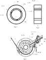
- At least one slotted groove 11, 12 is formed in each of the first bearing 9 and the second bearing 10 for receiving and providing the CIP fluid to the bearings 9, 10, as shown in Figs. 3 and 4 .
- Each bearing 9, 10 may have at least one slotted groove 11, 12 or a plurality of slotted grooves 11, 11a, 11b, 12.
- the plurality of slotted grooves 11, 11a, 11b may be equidistantly spaced about the inner diameter 9a of each of the bearings 9, 10.
- Each slotted groove 11, 11a, 11b, 12 may extend radially outwardly from the inner diameter 9a and have any suitable shape, such as a hemispherical shape.
- the slotted grooves 11, 11a, 11b, 12 may be through-holes that extend through an entire longitudinal length L of the respective bearing 9, 10.
- Forming the slotted grooves 11, 11a, 11b, 12 to extend through the entire length L of the bearings 9, 10 is advantageous in that the CIP fluid is able to flow through the slotted grooves 11, 11a, 11b, 12 along the inner diameter 9a of each of the bearings 9, 10.
- the CIP fluid flows to contact surfaces 13, 14 between the inner diameter 9a of each of the bearings 9, 10 and the outer diameter of the each of the shafts 5, 6 in the area of the slip fit connection where the contact surfaces 13, 14 meet to form the slip fit connection between the bearings 9, 10 and the shafts 5, 6.
- the slotted grooves 11, 11a, 11b, 12 also provide pressure relief through the bearings 9, 10 during normal operation of the augers 3, 4 in the auger assembly 1.
- each of the bearings 9, 10 further include at least one locating pin 15, 16 that is provided in each bearing 9, 10 for preventing the bearings 9, 10 from rotating.
- the locating pins 15, 16 extend radially through the first and second bearings 9, 10.
- the locating pins 15, 16 may be secured to the respective bearing 9, 10 by seal welding a top of the pins 15, 16.
- the first and second bearings 9, 10 are attached to a mounting bracket 17 that is secured to the auger housing 2.
- the first and second bearings 9, 10 may be attached to a first face of the mounting bracket 17 and an opposing face of the mounting bracket 17 may be removably attachable or mountable to the auger housing 2, as shown in Fig. 1 .
- Arranging the bearings 9, 10 and the mounting bracket 17 to be removable relative to the auger housing 2 is advantageous in that the mounting bracket 17 may be mounted to an external door of the auger housing 2, such that the bearings 9, 10 are easily removable and replaceable within the auger assembly 1 through the external door.
- the mounting bracket 17 is also arranged to support a cleaning line or CIP fluid line 18 that is connected between the auger assembly 1 and a remotely arranged fluid source for supplying the CIP fluid to the auger assembly 1, and particularly to the first and second bearings 9, 10.
- the CIP fluid line 18 may be in the form of any suitable tubing, hose, or other fluid transfer device. Supporting the CIP fluid line 18 within the mounting bracket 17 ensures that the CIP fluid line 18 is in a fixed position in which the CIP fluid line 18 is arranged to direct the CIP fluid to the slotted grooves 11, 12 and the area in which the slip fit connection between the bearings 9, 10 and the shafts 5, 6 is formed.
- the bearings 9, 10 are secured against the mounting bracket 17 when assembled within the auger assembly 1.
- the bearings 9, 10 may be retained against the mounting bracket 17 by radially extending shoulders 19, 20 of the bearings 9, 10, as shown in Figs. 2 and 4 .
- Providing the bearings 9, 10 with the shoulders 19, 20 or any other suitable feature prevents thrust loading from displacing the bearings 9, 10 out of engagement and retainment within the mounting bracket 17 during operation of the auger assembly 1.
- the mounting bracket 17 may be attached to a wall 21 of the auger housing 2 by a plate 22 of the mounting bracket 17.
- the plate 22 may have any suitable shape, such as rectangular, and a first face 22a that is removably attached to the wall 21 of the auger housing 2 and a second face 22b opposing the first face 22a.
- the plate 22 may be secured to the housing 2 using any suitable fastening mechanism. Examples of suitable fastening mechanisms may include bolts, screws, or clamps.
- a mounting arm 23 may be attached to the second face 22b of the plate 22 of the mounting bracket 17.
- the mounting arm 23 extends from the plate 22 to the first and second bearings 9, 10 to connect the bearings 9, 10 to the auger housing 2 during normal operation of the auger assembly 1.
- the mounting arm 23 may be arranged at an angle relative to the plate 22 and the CIP fluid line 18 may extend through the mounting arm 23.
- the CIP fluid line 18 and the mounting arm 23 may be arranged concentrically such that the CIP fluid line 18 is also arranged at an angle relative to the plate 22.
- the CIP fluid line 18 is arranged to extend internally through the mounting arm 23 and externally away from the auger housing 2.
- the auger assembly 1 further includes a plurality of helical or spiral flights 24, 25 that are attached to the shafts 5, 6 for rotation with the shafts 5, 6.
- the first shaft 5 of the first auger 3 has a first spiral flight 24 attached to the first shaft 5 and the second shaft 6 of the second auger 4 has a second spiral flight 25 attached to the second shaft 6.
- the first flight 24 and the second flight 25 may be symmetrical to each other. As best shown in Fig.
- each auger 3, 4 includes an outlet 26, 27 for expelling the cheese curd out of the respective auger 3, 4.
- the first outlet 26 of the first shaft 5 is arranged at an opposite end 28 of the first shaft 5 opposite the end 7 that faces the end 8 of the second shaft 6.
- the second outlet 27 of the second shaft 6 is arranged at an opposite end 29 of the second shaft 6 opposite the end 8 that faces the end 7 of the first shaft 5.
- the outlets 26, 27 are in communication between the auger assembly 1 and a downstream location along the cheese processing line for conveying the cheese curd downstream.
- the shafts 5, 6 are driven by any suitable drive mechanism of the auger assembly 1.
- Each auger 3, 4 may have a drive system that enables the shafts 5, 6 to be driven independently from each other.
- the shafts 5, 6 may be driven hydraulically, pneumatically, electrically, or any combination thereof, and the drive mechanism may include a motor, such as a gearmotor.
- a first drive 30 may be arranged at the opposite end 28 of the first shaft 5 for driving the first shaft 5 and a second drive 31 may be arranged at the opposite end 29 of the second shaft 6 for driving the second shaft 6.
- the shafts 5, 6 are rotatably coupled to the drives 30, 31.
- the shafts 5, 6 may be coupled to motors of the drives 30, 31 using shrouds, splined connections, or any other suitable connections.
- the auger assembly 1 having the first auger 3 and the second auger 4 may be arranged along a cheese processing line 32 as part of a machine 33.
- the machine 33 may be a cheddaring machine for producing a cheddar type cheese that includes a plurality of conveyors or auger assemblies 1, 34, 35, 36 that are individually driven at pre-set and adjustable speeds.
- four conveyors may be used.
- Each auger assembly 1, 34, 35, 36 may be mounted above each other within a frame of the machine 33.
- the first conveyor 34 may be configured to receive particles of cheese curd which has been drained of whey from a location upstream of the machine 33 along the cheese processing line 32.
- the first conveyor 34 may include stirrers for further whey drainage.
- the cheese curd particles are then transferred to the second conveyor 35 which enables the beginning of the matting and fusing of the cheese curd.
- the third conveyor 36 receives the cheese curd from the second conveyor 35 for cheddaring.
- the cheese curd may be milled to chips of uniform size which are then received by the next conveyor, which is a mellowing conveyor that includes an auger assembly similar to the auger assembly 1 having the first auger 3 and the second auger 4.
- the auger assembly 1 may also be used in any earlier conveyor, such as a conveyor used in draining the cheese curd before reaching the first conveyor 34.
- the auger assembly 1 may also be suitable for use in other cheese processing lines used to produce types of cheese other than cheddar.
- salt is added to the cheese curd and remains on the cheese curd for diffusing into the cheese curd.
- the cheese curd may be further stirred during the mellowing process to prevent the cheese from fusing and to promote an even absorption of salt.
- the auger assembly 1 may also be suitable for use in a cheese production line that uses cheddaring but in which the milled chips are not salted, such as in the production of mozzarella and pizza cheeses.
- a CIP system 37 that is in fluid communication with the auger assembly 1, such as by using the CIP fluid line 18 (shown in Fig. 5 ), is actuated and operable for cleaning the bearings 9, 10 (shown in Figs. 1-6 ).
- the CIP system 37 may be configured to operate automatically for cleaning the bearings 9, 10 or cleaning the bearings 9, 10 at predetermined intervals during operation of the auger assembly 1.
- the CIP system 37 may also be manually activated.
- Using the CIP system 37 and forming the bearings 9, 10 to have the slotted grooves as described herein enables an automated CIP cleaning of the auger assembly 1 and the bearing components during normal operation of the auger assembly 1 to promote cleaning and sanitation of the bearings 9, 10 or other components of the auger assembly 1 without having to disassemble the auger assembly 1.
- a method 40 for operating an auger assembly 1 (shown in Fig. 1 ) arranged to rotate a first auger 3 and a second auger 4 to convey cheese curd downstream along a cheese processing line 32 (shown in Fig. 10 ) is schematically shown.
- a first step 41 of the method 40 includes supplying particles of cheese curd to the first auger 3 and the second auger 4 that are colinearly arranged in the auger assembly 1.
- the particles of cheese curd may be received from a previous conveyor 36 (shown in Fig. 10 ).
- a second step 42 of the method 40 includes driving a first shaft 5 of the first auger 3 and a second shaft 6 of the second auger 4.
- the shafts 5, 6 are independently driven relative to each either using a corresponding drive 30, 31 (shown in Fig. 7 ).
- the particles of cheese curd travel along each of the augers 3, 4 toward the outlets 26, 27 (shown in Fig. 7 ) of the respective auger 3, 4.
- a third step 43 of the method 40 includes expelling the particles of cheese curd through the outlets 26, 27 at an end of the first auger 3 and at an end of the second auger 4 to convey the particles of cheese curd downstream along the cheese processing line 32.
- a fourth step 44 of the method 40 includes supplying a cleaning fluid, such as a CIP fluid, directly to bearings 9, 10 in the first and second auger 3, 4 that are arranged for mounting the first and second rotatable shaft 5, 6 within the auger housing 2. Directing the CIP fluid to the contact surfaces 13, 14 of the bearings 9, 10 may improve the life of the bearings 9, 10 and ensure sanitation of the components in the auger assembly 1 during the production of cheese.
- a cleaning fluid such as a CIP fluid
- an auger assembly is used for receiving particles of cheese curd and conveying the particles of cheese curd downstream along a cheese processing line.
- the auger assembly includes an auger housing, a first auger having a first shaft extending through the auger housing, a second auger having a second shaft extending through the auger housing and arranged colinearly with the first shaft, a first bearing mounted to the auger housing and arranged at the end of the first shaft, and a second bearing mounted to the auger housing and arranged at the end of the second shaft.
- the second shaft has an end that faces an end of the first shaft, and the first bearing and second bearing are colinear and face each other. At least one slotted groove is formed in each of the first bearing and the second bearing to enable a cleaning fluid to contact a surface of the respective bearing.
- the at least one slotted groove may extend through an entire longitudinal length of the respective bearing.
- the first and second bearing may each have a slip fit connection with the first and second shaft, respectively.
- the first shaft and the second shaft may be axially spaced from each other by a predetermined distance.
- the first and second bearing may be fixedly secured to the auger housing and the first and second shaft may be rotatable relative to the first and second bearing within the auger housing.
- the auger assembly may include at least one locating pin arranged on each of the first and second bearing.
- the at least one locating pin may be seal welded to each of the first and second bearing.
- the auger assembly may include a mounting bracket that is attached to the first and second bearing.
- the auger assembly may include a cleaning fluid line that is supported by the mounting bracket to direct the cleaning fluid to the at least one slotted groove formed in each of the first and second bearing.
- Each of the first and second bearing may have a radially extending shoulder to retain the first and second bearing against the mounting bracket.
- the mounting bracket and the first and second bearing may be removably attachable to the auger housing.
- the mounting bracket may include a plate attached to a wall of the auger housing and a mounting arm extending from the plate to the first and second bearing.
- the auger assembly may further include a first spiral flight attached to the first shaft, a second spiral flight attached to the second shaft, a first outlet arranged at an opposite end of the first shaft opposite the end that faces the end of the second shaft, and a second outlet arranged at an opposite end of the second shaft opposite the end that faces the end of the first shaft.
- the auger assembly may further include a first drive that is arranged at the opposite end of the first shaft for driving the first shaft, and a second drive that is arranged at the opposite end of the second shaft for driving the second shaft.
- a method for operating an auger assembly arranged to rotate a first auger and a second auger to convey cheese curd downstream along a cheese processing line includes supplying particles of cheese curd to the first auger and the second auger that are colinearly arranged, driving a first shaft of the first auger and a second shaft of the second auger, expelling the particles of cheese curd through outlets at an end of the first auger and at an end of the second auger to convey the particles of cheese curd downstream along the cheese processing line, and supplying a cleaning fluid directly to bearings in the first and second auger that are arranged for mounting the first and second shaft within an auger housing.
Landscapes
- Life Sciences & Earth Sciences (AREA)
- Animal Husbandry (AREA)
- Environmental Sciences (AREA)
- Engineering & Computer Science (AREA)
- Mechanical Engineering (AREA)
- Chemical & Material Sciences (AREA)
- Food Science & Technology (AREA)
- Polymers & Plastics (AREA)
- Cleaning In General (AREA)
Abstract
Description
- The invention relates to a method and assembly for receiving and conveying particles of cheese curd downstream along a cheese processing line, where augers are used to receive and convey the cheese particles.
- Different types of cheese may be produced using different types of production processes. For example, a production process for producing cheddar cheese may include cheddaring, milling, and salting of particles of cheese curd. Salting the cheese curd advantageously causes more moisture to be expelled from the curd. The production process for a producing cheddar cheese may include using a cheddaring machine that includes a plurality of conveyors. A first conveyor is configured to receive a curd mixture that has been drained of whey. The curd then travels downstream to additional conveyors for matting, fusing, and cheddaring. The curd is then moved further downstream where the curd is milled to chips or stirred depending on the type of cheese to be produced. For example, producing a Colby type of cheese may require stirred curd. The curd may then be salted while being conveyed to a final conveyor for mellowing.
- The conveyors of the cheddaring machine used during the draining, salting, and/or mellowing processes may be auger-type conveyors. Cleaning the augers is generally performed using a plurality of spray nozzles that randomly spray along the auger. However, conventional spray nozzles used to clean the augers may not be suitable for thoroughly cleaning and sanitizing all of the components of the auger, particularly in narrow regions where auger bearings and other components are located. Conventional spray nozzles are disadvantageous in that the augers may require manual disassembly and removal of the components for cleaning, which is also known as a clean out of place (COP) system.
- It is an object of the invention to at least partly overcome one or more limitations of the prior art. In particular, it is an object to provide an auger assembly that is configured to enable a clean-in-place (CIP) fluid to contact the surfaces of adjacent bearings of the auger assemblies during operation of the auger assembly.
- According to an aspect of the invention, an auger assembly is used for receiving particles of cheese curd and conveying the particles of cheese curd downstream along a cheese processing line. The auger assembly includes an auger housing, a first auger having a first shaft extending through the auger housing, a second auger having a second shaft extending through the auger housing and arranged colinearly with the first shaft, a first bearing mounted to the auger housing and arranged at the end of the first shaft, and a second bearing mounted to the auger housing and arranged at the end of the second shaft. The second shaft has an end that faces an end of the first shaft, and the first bearing and second bearing are colinear and face each other. At least one slotted groove is formed in each of the first bearing and the second bearing to enable a cleaning fluid to contact a surface of the respective bearing.
- The auger assembly described herein is advantageous in enabling a CIP system which directs cleaning fluid to the bearings of the shafts. The CIP fluid is introduced down the rotatable shafts of each auger to flood the area where the bearings are located with the CIP fluid. The bearings are connected to the shafts with a slip fit connection and the slotted grooves enable the CIP fluid to travel down the shafts through the grooves to cover the area where the connection between the bearings and the shafts is formed. Using the grooves and a CIP system, which may be automated, reduces the burden of cleaning the auger assembly as compared with manual, clean out of place (COP) systems in which the auger assembly is disassembled for cleaning bearings.
- According to another aspect of the invention, a method for operating an auger assembly arranged to rotate a first auger and a second auger to convey cheese curd downstream along a cheese processing line includes supplying particles of cheese curd to the first auger and the second auger that are colinearly arranged, driving a first shaft of the first auger and a second shaft of the second auger, expelling the particles of cheese curd through outlets at an end of the first auger and at an end of the second auger to convey the particles of cheese curd downstream along the cheese processing line, and supplying a cleaning fluid directly to bearings in the first and second auger that are arranged for mounting the first and second shaft within an auger housing.
- Although various aspects of the invention are set out in the accompanying independent claims, other aspects of the invention may include any combination of features from the described features and/or the accompanying dependent claims with the features of the independent claims, and not only the combinations explicitly set out in the accompanying claims.
- Features of the invention will now be described, by way of example, with reference to the accompanying schematic drawings, where:
-
Fig. 1 is a perspective view of an auger assembly for receiving particles of cheese curd and conveying the particles of cheese curd downstream along a cheese processing line. -
Fig. 2 is a top sectional view of the auger assembly shown inFig. 1 . -
Fig. 3 is a front sectional view of a bearing of the auger assembly shown inFig. 1 . -
Fig. 4 is a side sectional view of the bearing shown inFig. 3 . -
Fig. 5 is a front sectional view of the auger assembly shown inFig. 1 . -
Fig. 6 is a detailed sectional view of colinear bearings and a mounting bracket for the bearings of an auger assembly like the auger assembly shown inFig. 1 . -
Fig. 7 is a sectional view of a conveying auger that includes the auger assembly shown inFig. 1 . -
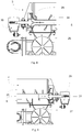
Fig. 8 is a detailed sectional view of a first side of the conveying auger shown inFig. 7 . -
Fig. 9 is a detailed sectional view of a second side opposite the first side of the conveying auger shown inFig. 7 . -
Fig. 10 is a schematic drawing showing an exemplary cheese processing line. -
Fig. 11 is a flow chart of a method of operating an auger assembly like the auger assembly ofFig. 1 to convey cheese curd downstream along a cheese processing line. - The method and system according to the present invention has particular application in a cheese processing line that uses conveyors, such as auger-type conveyors for receiving particles of cheese curd and conveying the particles of cheese curd downstream along a cheese processing line. Augers may be used at various stages along a cheese processing line configured for producing a cheddar type of cheese. For example, augers may be used to convey the cheese curd during the draining, salting, and/or mellowing stages of cheese production. Other types of cheese production lines may also use augers for producing types of cheeses other than cheddar.
- The method and assembly use an auger assembly for receiving particles of cheese curd and conveying the particles of cheese curd downstream along a cheese processing line. The auger assembly includes an auger housing, a first auger having a first shaft extending through the auger housing, a second auger having a second shaft extending through the auger housing and arranged colinearly with the first shaft, a first bearing mounted to the auger housing and arranged at the end of the first shaft, and a second bearing mounted to the auger housing and arranged at the end of the second shaft. The second shaft has an end that faces an end of the first shaft, and the first bearing and second bearing are colinear and facing each other.
- Advantageously, a slotted groove is formed in each of the bearings to enable a clean in place (CIP) fluid to contact surfaces of the bearings, such that cleaning of the bearings is ensured. The slotted grooves may extend through an entire longitudinal length of the bearings to enable the CIP fluid to travel along the auger shafts by way of the grooves and across the area where the bearings are connected with the shafts. The bearings are also removably mounted to a housing of the auger assembly using a mounting bracket which also supports the CIP fluid line to direct the CIP fluid to the slotted grooves. Thus, the bearings are easily replaceable within the auger assembly. Using the bearings and CIP system enables cleaning during normal operation of the auger assembly which subsequently improves the life of the bearings and is less burdensome than the conventionally used clean out of place (COP) system in which the auger is manually disassembled for cleaning the bearings.
- Referring first to
Figs. 1-6 , anexemplary auger assembly 1 for receiving particles of cheese curd and conveying the particles of cheese curd downstream along a cheese processing line is shown. Theauger assembly 1 includes anauger housing 2 that is configured to surround and support afirst auger 3 and asecond auger 4, such that theauger assembly 1 may be a dual auger assembly. In particular applications, only one auger may be provided or more than two augers may be provided. Thefirst auger 3 has afirst shaft 5 and thesecond auger 4 has asecond shaft 6. Thefirst shaft 5 and thesecond shaft 6 each extend through theauger housing 2. Theauger housing 2 may have any suitable shape, and theauger housing 2 may be at least partially cylindrical in shape such that the cylindrical portion of thehousing 2 surrounds theshafts - As best shown in
Fig. 2 , thefirst shaft 5 and thesecond shaft 6 are colinearly arranged and rotatable about a common longitudinal axis L. Thefirst shaft 5 has anend 7 that faces anend 8 of thesecond shaft 6. Theend 7 and theend 8 may be axially spaced from each other by a predetermined distance D1 such that thefirst shaft 5 and thesecond shaft 6 are also axially spaced by the predetermined distance D1, which may be any suitable distance. For example, the predetermined distance D1 may be between 0.51 centimeters (0.20 inches) and 0.76 centimeters (0.30 inches). Spacing thefirst shaft 5 and thesecond shaft 6 relative to each other enables thefirst auger 3 and thesecond auger 4 to operate independently from each other. Independent operation of theaugers auger assembly 1. - The
first auger 3 has afirst bearing 9 that is removably mounted to theauger housing 2 and arranged at theend 7 of thefirst shaft 5. Similarly, thesecond auger 4 has asecond bearing 10 that is removably mounted to theauger housing 2 and arranged at theend 8 of thesecond shaft 6. Thebearings first shaft 5 and thesecond shaft 6 within theauger housing 2. Thebearings shafts respective bearing first bearing 9 and thesecond bearing 10 are colinear and arranged along the longitudinal axis L. The first andsecond bearings ends second shafts - The first and
second bearings second bearings second bearings second bearings second bearings Fig. 2 , the first andsecond bearings respective shaft second bearings second shafts inner diameter 9a of eachbearing respective shaft - At least one slotted groove 11, 12 is formed in each of the
first bearing 9 and thesecond bearing 10 for receiving and providing the CIP fluid to thebearings Figs. 3 and 4 . Eachbearing grooves grooves inner diameter 9a of each of thebearings groove inner diameter 9a and have any suitable shape, such as a hemispherical shape. As shown inFig. 4 , the slottedgrooves respective bearing - Forming the slotted
grooves bearings grooves inner diameter 9a of each of thebearings Fig. 2 , the CIP fluid flows to contactsurfaces inner diameter 9a of each of thebearings shafts bearings shafts grooves bearings augers auger assembly 1. As best shown inFigs. 1 ,5 and6 , each of thebearings pin bearing bearings second bearings respective bearing pins - The first and
second bearings bracket 17 that is secured to theauger housing 2. The first andsecond bearings bracket 17 and an opposing face of the mountingbracket 17 may be removably attachable or mountable to theauger housing 2, as shown inFig. 1 . Arranging thebearings bracket 17 to be removable relative to theauger housing 2 is advantageous in that the mountingbracket 17 may be mounted to an external door of theauger housing 2, such that thebearings auger assembly 1 through the external door. The mountingbracket 17 is also arranged to support a cleaning line orCIP fluid line 18 that is connected between theauger assembly 1 and a remotely arranged fluid source for supplying the CIP fluid to theauger assembly 1, and particularly to the first andsecond bearings Figs. 1 ,5 and6 , theCIP fluid line 18 may be in the form of any suitable tubing, hose, or other fluid transfer device. Supporting theCIP fluid line 18 within the mountingbracket 17 ensures that theCIP fluid line 18 is in a fixed position in which theCIP fluid line 18 is arranged to direct the CIP fluid to the slotted grooves 11, 12 and the area in which the slip fit connection between thebearings shafts - The
bearings bracket 17 when assembled within theauger assembly 1. For example, thebearings bracket 17 by radially extendingshoulders bearings Figs. 2 and4 . Providing thebearings shoulders bearings bracket 17 during operation of theauger assembly 1. As shown inFigs. 1 ,5 and6 , the mountingbracket 17 may be attached to awall 21 of theauger housing 2 by aplate 22 of the mountingbracket 17. Theplate 22 may have any suitable shape, such as rectangular, and afirst face 22a that is removably attached to thewall 21 of theauger housing 2 and asecond face 22b opposing thefirst face 22a. Theplate 22 may be secured to thehousing 2 using any suitable fastening mechanism. Examples of suitable fastening mechanisms may include bolts, screws, or clamps. - A mounting
arm 23 may be attached to thesecond face 22b of theplate 22 of the mountingbracket 17. The mountingarm 23 extends from theplate 22 to the first andsecond bearings bearings auger housing 2 during normal operation of theauger assembly 1. The mountingarm 23 may be arranged at an angle relative to theplate 22 and theCIP fluid line 18 may extend through the mountingarm 23. TheCIP fluid line 18 and the mountingarm 23 may be arranged concentrically such that theCIP fluid line 18 is also arranged at an angle relative to theplate 22. TheCIP fluid line 18 is arranged to extend internally through the mountingarm 23 and externally away from theauger housing 2. - Referring in addition to
Figs. 7-9 , portions of the entire auger assembly are shown inFig. 7 ,Fig. 8 shows a detailed view of a portion of thefirst auger 3, andFig. 9 shows a detailed view of a portion of thesecond auger 4. Theauger assembly 1 further includes a plurality of helical orspiral flights shafts shafts first shaft 5 of thefirst auger 3 has afirst spiral flight 24 attached to thefirst shaft 5 and thesecond shaft 6 of thesecond auger 4 has asecond spiral flight 25 attached to thesecond shaft 6. Thefirst flight 24 and thesecond flight 25 may be symmetrical to each other. As best shown inFig. 7 , theflights respective shaft augers auger outlet respective auger first outlet 26 of thefirst shaft 5 is arranged at anopposite end 28 of thefirst shaft 5 opposite theend 7 that faces theend 8 of thesecond shaft 6. Thesecond outlet 27 of thesecond shaft 6 is arranged at anopposite end 29 of thesecond shaft 6 opposite theend 8 that faces theend 7 of thefirst shaft 5. Theoutlets auger assembly 1 and a downstream location along the cheese processing line for conveying the cheese curd downstream. - The
shafts auger assembly 1. Eachauger shafts shafts first drive 30 may be arranged at theopposite end 28 of thefirst shaft 5 for driving thefirst shaft 5 and asecond drive 31 may be arranged at theopposite end 29 of thesecond shaft 6 for driving thesecond shaft 6. Theshafts drives shafts drives - Referring in addition to
Fig. 10 , theauger assembly 1 having thefirst auger 3 and thesecond auger 4 may be arranged along acheese processing line 32 as part of amachine 33. For example, themachine 33 may be a cheddaring machine for producing a cheddar type cheese that includes a plurality of conveyors orauger assemblies auger assembly machine 33. Thefirst conveyor 34 may be configured to receive particles of cheese curd which has been drained of whey from a location upstream of themachine 33 along thecheese processing line 32. Thefirst conveyor 34 may include stirrers for further whey drainage. The cheese curd particles are then transferred to thesecond conveyor 35 which enables the beginning of the matting and fusing of the cheese curd. Thethird conveyor 36 receives the cheese curd from thesecond conveyor 35 for cheddaring. - At the end of the
third conveyor 36, the cheese curd may be milled to chips of uniform size which are then received by the next conveyor, which is a mellowing conveyor that includes an auger assembly similar to theauger assembly 1 having thefirst auger 3 and thesecond auger 4. Theauger assembly 1 may also be used in any earlier conveyor, such as a conveyor used in draining the cheese curd before reaching thefirst conveyor 34. Theauger assembly 1 may also be suitable for use in other cheese processing lines used to produce types of cheese other than cheddar. During the movement of the cheese curd from thethird conveyor 36 to the mellowing conveyor, orauger assembly 1, salt is added to the cheese curd and remains on the cheese curd for diffusing into the cheese curd. The cheese curd may be further stirred during the mellowing process to prevent the cheese from fusing and to promote an even absorption of salt. Theauger assembly 1 may also be suitable for use in a cheese production line that uses cheddaring but in which the milled chips are not salted, such as in the production of mozzarella and pizza cheeses. - During the movement of the cheese curd within the mellowing conveyor, a
CIP system 37 that is in fluid communication with theauger assembly 1, such as by using the CIP fluid line 18 (shown inFig. 5 ), is actuated and operable for cleaning thebearings 9, 10 (shown inFigs. 1-6 ). TheCIP system 37 may be configured to operate automatically for cleaning thebearings bearings auger assembly 1. TheCIP system 37 may also be manually activated. Using theCIP system 37 and forming thebearings auger assembly 1 and the bearing components during normal operation of theauger assembly 1 to promote cleaning and sanitation of thebearings auger assembly 1 without having to disassemble theauger assembly 1. - Referring now to
Fig. 11 , amethod 40 for operating an auger assembly 1 (shown inFig. 1 ) arranged to rotate afirst auger 3 and asecond auger 4 to convey cheese curd downstream along a cheese processing line 32 (shown inFig. 10 ) is schematically shown. Afirst step 41 of themethod 40 includes supplying particles of cheese curd to thefirst auger 3 and thesecond auger 4 that are colinearly arranged in theauger assembly 1. The particles of cheese curd may be received from a previous conveyor 36 (shown inFig. 10 ). When the particles of cheese curd are supplied to the auger assembly, asecond step 42 of themethod 40 includes driving afirst shaft 5 of thefirst auger 3 and asecond shaft 6 of thesecond auger 4. Theshafts drive 30, 31 (shown inFig. 7 ). The particles of cheese curd travel along each of theaugers outlets 26, 27 (shown inFig. 7 ) of therespective auger - After the particles of cheese curd have travelled along the
augers third step 43 of themethod 40 includes expelling the particles of cheese curd through theoutlets first auger 3 and at an end of thesecond auger 4 to convey the particles of cheese curd downstream along thecheese processing line 32. Afourth step 44 of themethod 40 includes supplying a cleaning fluid, such as a CIP fluid, directly tobearings second auger rotatable shaft auger housing 2. Directing the CIP fluid to the contact surfaces 13, 14 of thebearings bearings auger assembly 1 during the production of cheese. - According to an aspect of the invention, an auger assembly is used for receiving particles of cheese curd and conveying the particles of cheese curd downstream along a cheese processing line. The auger assembly includes an auger housing, a first auger having a first shaft extending through the auger housing, a second auger having a second shaft extending through the auger housing and arranged colinearly with the first shaft, a first bearing mounted to the auger housing and arranged at the end of the first shaft, and a second bearing mounted to the auger housing and arranged at the end of the second shaft. The second shaft has an end that faces an end of the first shaft, and the first bearing and second bearing are colinear and face each other. At least one slotted groove is formed in each of the first bearing and the second bearing to enable a cleaning fluid to contact a surface of the respective bearing.
- The at least one slotted groove may extend through an entire longitudinal length of the respective bearing.
- The first and second bearing may each have a slip fit connection with the first and second shaft, respectively.
- The first shaft and the second shaft may be axially spaced from each other by a predetermined distance.
- The first and second bearing may be fixedly secured to the auger housing and the first and second shaft may be rotatable relative to the first and second bearing within the auger housing.
- The auger assembly may include at least one locating pin arranged on each of the first and second bearing.
- The at least one locating pin may be seal welded to each of the first and second bearing.
- The auger assembly may include a mounting bracket that is attached to the first and second bearing.
- The auger assembly may include a cleaning fluid line that is supported by the mounting bracket to direct the cleaning fluid to the at least one slotted groove formed in each of the first and second bearing.
- Each of the first and second bearing may have a radially extending shoulder to retain the first and second bearing against the mounting bracket.
- The mounting bracket and the first and second bearing may be removably attachable to the auger housing.
- The mounting bracket may include a plate attached to a wall of the auger housing and a mounting arm extending from the plate to the first and second bearing.
- The auger assembly may further include a first spiral flight attached to the first shaft, a second spiral flight attached to the second shaft, a first outlet arranged at an opposite end of the first shaft opposite the end that faces the end of the second shaft, and a second outlet arranged at an opposite end of the second shaft opposite the end that faces the end of the first shaft.
- The auger assembly may further include a first drive that is arranged at the opposite end of the first shaft for driving the first shaft, and a second drive that is arranged at the opposite end of the second shaft for driving the second shaft.
- According to another aspect of the invention, a method for operating an auger assembly arranged to rotate a first auger and a second auger to convey cheese curd downstream along a cheese processing line includes supplying particles of cheese curd to the first auger and the second auger that are colinearly arranged, driving a first shaft of the first auger and a second shaft of the second auger, expelling the particles of cheese curd through outlets at an end of the first auger and at an end of the second auger to convey the particles of cheese curd downstream along the cheese processing line, and supplying a cleaning fluid directly to bearings in the first and second auger that are arranged for mounting the first and second shaft within an auger housing.
- While the invention has been described with reference to one or more preferred features, which features have been set forth in considerable detail for the purposes of making a complete disclosure of the invention, such features are merely exemplary and are not intended to be limiting or represent an exhaustive enumeration of all aspects of the invention. The scope of the invention, therefore, shall be defined solely by the following claims. Further, it will be apparent to those of skill in the art that numerous changes may be made in such details without departing from the spirit and the principles of the invention.
Claims (15)
- An auger assembly (1) for receiving particles of cheese curd and conveying the particles of cheese curd downstream along a cheese processing line (32), the auger assembly (1) comprising:an auger housing (2),a first auger (3) having a first shaft (5) extending through the auger housing (2),a second auger (4) having a second shaft (6) extending through the auger housing (2) and arranged colinearly with the first shaft (5), the second shaft (6) having an end (8) that faces an end (7) of the first shaft (5),a first bearing (9) mounted to the auger housing (2) and arranged at the end (7) of the first shaft (5), anda second bearing (10) mounted to the auger housing (2) and arranged at the end (8) of the second shaft (6), the first bearing (9) and second bearing (10) being colinear and facing each other,characterized byat least one slotted groove (11, 12) formed in each of the first bearing (9) and the second bearing (10) to enable a cleaning fluid to contact a surface (13, 14) of the respective bearing (9, 10).
- The auger assembly (1) according to claim 1, wherein the at least one slotted groove (11, 12) extends through an entire longitudinal length (L) of the respective bearing (9, 10).
- The auger assembly (1) according to any preceding claim, wherein the first and second bearing (9, 10) each have a slip fit connection (13, 14) with the first and second shaft (5, 6), respectively.
- The auger assembly (1) according to any preceding claim, wherein the first shaft (5) and the second shaft (6) are axially spaced from each other by a predetermined distance (D).
- The auger assembly (1) according to any preceding claim, wherein the first and second bearing (9, 10) are fixedly secured to the auger housing (2) and the first and second shaft (5, 6) are rotatable relative to the first and second bearing (9, 10) within the auger housing (2).
- The auger assembly (1) according to any preceding claim, further comprising at least one locating pin (15, 16) arranged on each of the first and second bearing (9, 10).
- The auger assembly (1) according to claim 6, wherein the at least one locating pin (15, 16) is seal welded to each of the first and second bearing (9, 10).
- The auger assembly (1) according to any preceding claim, further comprising a mounting bracket (17) that is attached to the first and second bearing (9, 10).
- The auger assembly (1) according to claim 8, further comprising a cleaning fluid line (18) that is supported by the mounting bracket (17) to direct the cleaning fluid to the at least one slotted groove (11, 12) formed in each of the first and second bearing (9, 10).
- The auger assembly (1) according to claim 8 or 9, wherein each of the first and second bearing (9, 10) has a radially extending shoulder (19, 20) to retain the first and second bearing (9, 10) against the mounting bracket (17).
- The auger assembly (1) according to any of claims 8-10, wherein the mounting bracket (17) and the first and second bearing (9, 10) are removably attachable to the auger housing (2).
- The auger assembly (1) according to any of claims 8-11, wherein the mounting bracket (17) includes a plate (22) attached to a wall (21) of the auger housing (2) and a mounting arm (23) extending from the plate (22) to the first and second bearing (9, 10).
- The auger assembly (1) according to any preceding claim, further comprising:a first spiral flight (24) attached to the first shaft (5),a second spiral flight (25) attached to the second shaft (6),a first outlet (26) arranged at an opposite end (28) of the first shaft (5) opposite the end (7) that faces the end (8) of the second shaft (6), anda second outlet (27) arranged at an opposite end (29) of the second shaft (6) opposite the end (8) that faces the end (7) of the first shaft (5).
- The auger assembly (1) according to claim 13, further comprising:a first drive (30) that is arranged at the opposite end (28) of the first shaft (5) for driving the first shaft (5), anda second drive (31) that is arranged at the opposite end (29) of the second shaft (6) for driving the second shaft (6).
- A method (40) for operating an auger assembly (1) arranged to rotate a first auger (3) and a second auger (4) to convey cheese curd downstream along a cheese processing line (32), the method comprising:supplying (41) particles of cheese curd to the first auger (3) and the second auger (4) that are colinearly arranged,driving (42) a first shaft (5) of the first auger (3) and a second shaft (6) of the second auger (4),expelling (43) the particles of cheese curd through outlets (26, 27) at an end of the first auger (3) and at an end of the second auger (4) to convey the particles of cheese curd downstream along the cheese processing line (32), andsupplying (44) a cleaning fluid directly to bearings (9, 10) in the first and second auger (3, 4) that are arranged for mounting the first and second shaft (5, 6) within an auger housing (2).
Applications Claiming Priority (1)
| Application Number | Priority Date | Filing Date | Title |
|---|---|---|---|
| US16/233,155 US11134651B2 (en) | 2018-12-27 | 2018-12-27 | Dual auger internal clean-in-place bearing |
Publications (2)
| Publication Number | Publication Date |
|---|---|
| EP3673730A1 true EP3673730A1 (en) | 2020-07-01 |
| EP3673730B1 EP3673730B1 (en) | 2021-11-17 |
Family
ID=68917687
Family Applications (1)
| Application Number | Title | Priority Date | Filing Date |
|---|---|---|---|
| EP19216656.9A Active EP3673730B1 (en) | 2018-12-27 | 2019-12-16 | Auger assembly for conveying cheese curd |
Country Status (2)
| Country | Link |
|---|---|
| US (1) | US11134651B2 (en) |
| EP (1) | EP3673730B1 (en) |
Cited By (1)
| Publication number | Priority date | Publication date | Assignee | Title |
|---|---|---|---|---|
| US11134651B2 (en) * | 2018-12-27 | 2021-10-05 | Tetra Laval Holdings & Finance S.A. | Dual auger internal clean-in-place bearing |
Families Citing this family (1)
| Publication number | Priority date | Publication date | Assignee | Title |
|---|---|---|---|---|
| CN118901588A (en) * | 2024-07-17 | 2024-11-08 | 嘉兴市海诺科贸有限公司 | Low temperature resistant porous nanometer cheese handheld bar forming equipment |
Citations (3)
| Publication number | Priority date | Publication date | Assignee | Title |
|---|---|---|---|---|
| US3531297A (en) * | 1968-10-07 | 1970-09-29 | Leprino Cheese Mfg Co | Manufacture of pasta cheese |
| AU459958B2 (en) * | 1973-05-25 | 1975-04-10 | JR. and JAMES GERALD LEONOV MICHAELA. LEONOV | Apparatus for mixing cheese curd |
| CN207404385U (en) * | 2017-11-16 | 2018-05-25 | 无锡市宝御达机械设备制造有限公司 | Material cup applied to charging (feeding) equipment |
Family Cites Families (7)
| Publication number | Priority date | Publication date | Assignee | Title |
|---|---|---|---|---|
| US3272317A (en) * | 1963-07-10 | 1966-09-13 | Fred Kelly & Sons Proprietary | Conveyors |
| US3289819A (en) * | 1965-08-12 | 1966-12-06 | Galion Jeffrey Mfg Co | Spiral conveyor coupling means |
| US3713220A (en) * | 1970-07-13 | 1973-01-30 | Leprino Cheese Mfg Co | Apparatus for mixing cheese curd |
| US4384643A (en) * | 1979-12-19 | 1983-05-24 | Cone Joseph R | Screw conveyor hanger including disassembly means |
| US4815585A (en) * | 1988-02-23 | 1989-03-28 | Custom Metalcraft, Inc. | Sanitary hanger bearing assembly |
| IT1395664B1 (en) * | 2009-09-02 | 2012-10-16 | Cmt Costr Mecc & Tec | APPARATUS FOR MILK CAGLIATA SPINNING FOR THE PRODUCTION OF FILATA PASTA CHEESES |
| US11134651B2 (en) * | 2018-12-27 | 2021-10-05 | Tetra Laval Holdings & Finance S.A. | Dual auger internal clean-in-place bearing |
-
2018
- 2018-12-27 US US16/233,155 patent/US11134651B2/en active Active
-
2019
- 2019-12-16 EP EP19216656.9A patent/EP3673730B1/en active Active
Patent Citations (3)
| Publication number | Priority date | Publication date | Assignee | Title |
|---|---|---|---|---|
| US3531297A (en) * | 1968-10-07 | 1970-09-29 | Leprino Cheese Mfg Co | Manufacture of pasta cheese |
| AU459958B2 (en) * | 1973-05-25 | 1975-04-10 | JR. and JAMES GERALD LEONOV MICHAELA. LEONOV | Apparatus for mixing cheese curd |
| CN207404385U (en) * | 2017-11-16 | 2018-05-25 | 无锡市宝御达机械设备制造有限公司 | Material cup applied to charging (feeding) equipment |
Cited By (1)
| Publication number | Priority date | Publication date | Assignee | Title |
|---|---|---|---|---|
| US11134651B2 (en) * | 2018-12-27 | 2021-10-05 | Tetra Laval Holdings & Finance S.A. | Dual auger internal clean-in-place bearing |
Also Published As
| Publication number | Publication date |
|---|---|
| US20200205366A1 (en) | 2020-07-02 |
| EP3673730B1 (en) | 2021-11-17 |
| US11134651B2 (en) | 2021-10-05 |
Similar Documents
| Publication | Publication Date | Title |
|---|---|---|
| EP3673730B1 (en) | Auger assembly for conveying cheese curd | |
| US5985346A (en) | Method of using and cleaning a dough transport device | |
| EP2446729A1 (en) | A machine for harvesting maize | |
| CN107667063A (en) | The method of the conveyer belt system for transporting food and the conveyer belt for cleaning conveyer belt system | |
| US4078874A (en) | Apparatus for conveying ground cheese | |
| US20110103992A1 (en) | Gear pumps and methods for using gear pumps | |
| US11326597B2 (en) | Food product pump with impeller and star wheel | |
| US5962036A (en) | Twin screw extruder with high-speed bearing support | |
| CN208159674U (en) | A kind of cream frothing machine | |
| CA2946066C (en) | AUTOMATIC TABLETOP MACHINE DESIGNED FOR KNEADING AND EXTRUDING PASTA | |
| JPH05207841A (en) | Dual pump device for meat filling device | |
| US20020098255A1 (en) | Auger for a dough transport device | |
| KR101846302B1 (en) | kneader | |
| JP7702725B2 (en) | In-line Dispersion Device | |
| CN206238224U (en) | A kind of full-automatic noodle slicing machine | |
| CN211548810U (en) | Concrete injection apparatus with prevent stifled injector head effect | |
| JP5617702B2 (en) | Meat transfer screw conveyor | |
| JP2005193206A (en) | Apparatus for stirring plastic fat and apparatus for supplying plastic fat with stirring apparatus | |
| KR101847116B1 (en) | Automatic machine for meat source added | |
| CN220238727U (en) | Pipeline sepiolite fiber scattering machine | |
| EP1352729A1 (en) | Screw extruder with discharge pump | |
| CN222020311U (en) | Milk product processing preheating device | |
| JP2004306605A (en) | Improvement of equipment for manufacturing concrete pipe and method of manufacturing concrete pipe | |
| AU2018443041B2 (en) | Device and method for continuously conveying and plasticising cheese curd | |
| NZ774182B2 (en) | Device and method for continuously conveying and plasticising cheese curd |
Legal Events
| Date | Code | Title | Description |
|---|---|---|---|
| PUAI | Public reference made under article 153(3) epc to a published international application that has entered the european phase |
Free format text: ORIGINAL CODE: 0009012 |
|
| STAA | Information on the status of an ep patent application or granted ep patent |
Free format text: STATUS: THE APPLICATION HAS BEEN PUBLISHED |
|
| AK | Designated contracting states |
Kind code of ref document: A1 Designated state(s): AL AT BE BG CH CY CZ DE DK EE ES FI FR GB GR HR HU IE IS IT LI LT LU LV MC MK MT NL NO PL PT RO RS SE SI SK SM TR |
|
| AX | Request for extension of the european patent |
Extension state: BA ME |
|
| RIN1 | Information on inventor provided before grant (corrected) |
Inventor name: OLSON, MICHAEL Inventor name: JOHNSON, KYLE |
|
| STAA | Information on the status of an ep patent application or granted ep patent |
Free format text: STATUS: REQUEST FOR EXAMINATION WAS MADE |
|
| 17P | Request for examination filed |
Effective date: 20210111 |
|
| RBV | Designated contracting states (corrected) |
Designated state(s): AL AT BE BG CH CY CZ DE DK EE ES FI FR GB GR HR HU IE IS IT LI LT LU LV MC MK MT NL NO PL PT RO RS SE SI SK SM TR |
|
| GRAP | Despatch of communication of intention to grant a patent |
Free format text: ORIGINAL CODE: EPIDOSNIGR1 |
|
| STAA | Information on the status of an ep patent application or granted ep patent |
Free format text: STATUS: GRANT OF PATENT IS INTENDED |
|
| INTG | Intention to grant announced |
Effective date: 20210622 |
|
| RIN1 | Information on inventor provided before grant (corrected) |
Inventor name: JOHNSON, KYLE Inventor name: OLSON, MICHAEL |
|
| GRAS | Grant fee paid |
Free format text: ORIGINAL CODE: EPIDOSNIGR3 |
|
| GRAA | (expected) grant |
Free format text: ORIGINAL CODE: 0009210 |
|
| STAA | Information on the status of an ep patent application or granted ep patent |
Free format text: STATUS: THE PATENT HAS BEEN GRANTED |
|
| AK | Designated contracting states |
Kind code of ref document: B1 Designated state(s): AL AT BE BG CH CY CZ DE DK EE ES FI FR GB GR HR HU IE IS IT LI LT LU LV MC MK MT NL NO PL PT RO RS SE SI SK SM TR |
|
| REG | Reference to a national code |
Ref country code: GB Ref legal event code: FG4D |
|
| REG | Reference to a national code |
Ref country code: IE Ref legal event code: FG4D |
|
| REG | Reference to a national code |
Ref country code: DE Ref legal event code: R096 Ref document number: 602019009359 Country of ref document: DE |
|
| REG | Reference to a national code |
Ref country code: AT Ref legal event code: REF Ref document number: 1447298 Country of ref document: AT Kind code of ref document: T Effective date: 20211215 |
|
| REG | Reference to a national code |
Ref country code: NL Ref legal event code: FP |
|
| REG | Reference to a national code |
Ref country code: LT Ref legal event code: MG9D |
|
| REG | Reference to a national code |
Ref country code: AT Ref legal event code: MK05 Ref document number: 1447298 Country of ref document: AT Kind code of ref document: T Effective date: 20211117 |
|
| PG25 | Lapsed in a contracting state [announced via postgrant information from national office to epo] |
Ref country code: RS Free format text: LAPSE BECAUSE OF FAILURE TO SUBMIT A TRANSLATION OF THE DESCRIPTION OR TO PAY THE FEE WITHIN THE PRESCRIBED TIME-LIMIT Effective date: 20211117 Ref country code: LT Free format text: LAPSE BECAUSE OF FAILURE TO SUBMIT A TRANSLATION OF THE DESCRIPTION OR TO PAY THE FEE WITHIN THE PRESCRIBED TIME-LIMIT Effective date: 20211117 Ref country code: FI Free format text: LAPSE BECAUSE OF FAILURE TO SUBMIT A TRANSLATION OF THE DESCRIPTION OR TO PAY THE FEE WITHIN THE PRESCRIBED TIME-LIMIT Effective date: 20211117 Ref country code: BG Free format text: LAPSE BECAUSE OF FAILURE TO SUBMIT A TRANSLATION OF THE DESCRIPTION OR TO PAY THE FEE WITHIN THE PRESCRIBED TIME-LIMIT Effective date: 20220217 Ref country code: AT Free format text: LAPSE BECAUSE OF FAILURE TO SUBMIT A TRANSLATION OF THE DESCRIPTION OR TO PAY THE FEE WITHIN THE PRESCRIBED TIME-LIMIT Effective date: 20211117 |
|
| PG25 | Lapsed in a contracting state [announced via postgrant information from national office to epo] |
Ref country code: IS Free format text: LAPSE BECAUSE OF FAILURE TO SUBMIT A TRANSLATION OF THE DESCRIPTION OR TO PAY THE FEE WITHIN THE PRESCRIBED TIME-LIMIT Effective date: 20220317 Ref country code: SE Free format text: LAPSE BECAUSE OF FAILURE TO SUBMIT A TRANSLATION OF THE DESCRIPTION OR TO PAY THE FEE WITHIN THE PRESCRIBED TIME-LIMIT Effective date: 20211117 Ref country code: PT Free format text: LAPSE BECAUSE OF FAILURE TO SUBMIT A TRANSLATION OF THE DESCRIPTION OR TO PAY THE FEE WITHIN THE PRESCRIBED TIME-LIMIT Effective date: 20220317 Ref country code: PL Free format text: LAPSE BECAUSE OF FAILURE TO SUBMIT A TRANSLATION OF THE DESCRIPTION OR TO PAY THE FEE WITHIN THE PRESCRIBED TIME-LIMIT Effective date: 20211117 Ref country code: NO Free format text: LAPSE BECAUSE OF FAILURE TO SUBMIT A TRANSLATION OF THE DESCRIPTION OR TO PAY THE FEE WITHIN THE PRESCRIBED TIME-LIMIT Effective date: 20220217 Ref country code: LV Free format text: LAPSE BECAUSE OF FAILURE TO SUBMIT A TRANSLATION OF THE DESCRIPTION OR TO PAY THE FEE WITHIN THE PRESCRIBED TIME-LIMIT Effective date: 20211117 Ref country code: HR Free format text: LAPSE BECAUSE OF FAILURE TO SUBMIT A TRANSLATION OF THE DESCRIPTION OR TO PAY THE FEE WITHIN THE PRESCRIBED TIME-LIMIT Effective date: 20211117 Ref country code: GR Free format text: LAPSE BECAUSE OF FAILURE TO SUBMIT A TRANSLATION OF THE DESCRIPTION OR TO PAY THE FEE WITHIN THE PRESCRIBED TIME-LIMIT Effective date: 20220218 Ref country code: ES Free format text: LAPSE BECAUSE OF FAILURE TO SUBMIT A TRANSLATION OF THE DESCRIPTION OR TO PAY THE FEE WITHIN THE PRESCRIBED TIME-LIMIT Effective date: 20211117 |
|
| PG25 | Lapsed in a contracting state [announced via postgrant information from national office to epo] |
Ref country code: SM Free format text: LAPSE BECAUSE OF FAILURE TO SUBMIT A TRANSLATION OF THE DESCRIPTION OR TO PAY THE FEE WITHIN THE PRESCRIBED TIME-LIMIT Effective date: 20211117 Ref country code: SK Free format text: LAPSE BECAUSE OF FAILURE TO SUBMIT A TRANSLATION OF THE DESCRIPTION OR TO PAY THE FEE WITHIN THE PRESCRIBED TIME-LIMIT Effective date: 20211117 Ref country code: RO Free format text: LAPSE BECAUSE OF FAILURE TO SUBMIT A TRANSLATION OF THE DESCRIPTION OR TO PAY THE FEE WITHIN THE PRESCRIBED TIME-LIMIT Effective date: 20211117 Ref country code: EE Free format text: LAPSE BECAUSE OF FAILURE TO SUBMIT A TRANSLATION OF THE DESCRIPTION OR TO PAY THE FEE WITHIN THE PRESCRIBED TIME-LIMIT Effective date: 20211117 Ref country code: DK Free format text: LAPSE BECAUSE OF FAILURE TO SUBMIT A TRANSLATION OF THE DESCRIPTION OR TO PAY THE FEE WITHIN THE PRESCRIBED TIME-LIMIT Effective date: 20211117 Ref country code: CZ Free format text: LAPSE BECAUSE OF FAILURE TO SUBMIT A TRANSLATION OF THE DESCRIPTION OR TO PAY THE FEE WITHIN THE PRESCRIBED TIME-LIMIT Effective date: 20211117 |
|
| REG | Reference to a national code |
Ref country code: DE Ref legal event code: R097 Ref document number: 602019009359 Country of ref document: DE |
|
| PG25 | Lapsed in a contracting state [announced via postgrant information from national office to epo] |
Ref country code: MC Free format text: LAPSE BECAUSE OF FAILURE TO SUBMIT A TRANSLATION OF THE DESCRIPTION OR TO PAY THE FEE WITHIN THE PRESCRIBED TIME-LIMIT Effective date: 20211117 |
|
| PLBE | No opposition filed within time limit |
Free format text: ORIGINAL CODE: 0009261 |
|
| STAA | Information on the status of an ep patent application or granted ep patent |
Free format text: STATUS: NO OPPOSITION FILED WITHIN TIME LIMIT |
|
| REG | Reference to a national code |
Ref country code: BE Ref legal event code: MM Effective date: 20211231 |
|
| 26N | No opposition filed |
Effective date: 20220818 |
|
| PG25 | Lapsed in a contracting state [announced via postgrant information from national office to epo] |
Ref country code: LU Free format text: LAPSE BECAUSE OF NON-PAYMENT OF DUE FEES Effective date: 20211216 Ref country code: IE Free format text: LAPSE BECAUSE OF NON-PAYMENT OF DUE FEES Effective date: 20211216 Ref country code: AL Free format text: LAPSE BECAUSE OF FAILURE TO SUBMIT A TRANSLATION OF THE DESCRIPTION OR TO PAY THE FEE WITHIN THE PRESCRIBED TIME-LIMIT Effective date: 20211117 |
|
| PG25 | Lapsed in a contracting state [announced via postgrant information from national office to epo] |
Ref country code: SI Free format text: LAPSE BECAUSE OF FAILURE TO SUBMIT A TRANSLATION OF THE DESCRIPTION OR TO PAY THE FEE WITHIN THE PRESCRIBED TIME-LIMIT Effective date: 20211117 Ref country code: FR Free format text: LAPSE BECAUSE OF NON-PAYMENT OF DUE FEES Effective date: 20220117 Ref country code: BE Free format text: LAPSE BECAUSE OF NON-PAYMENT OF DUE FEES Effective date: 20211231 |
|
| PG25 | Lapsed in a contracting state [announced via postgrant information from national office to epo] |
Ref country code: IT Free format text: LAPSE BECAUSE OF FAILURE TO SUBMIT A TRANSLATION OF THE DESCRIPTION OR TO PAY THE FEE WITHIN THE PRESCRIBED TIME-LIMIT Effective date: 20211117 |
|
| P01 | Opt-out of the competence of the unified patent court (upc) registered |
Effective date: 20230426 |
|
| PG25 | Lapsed in a contracting state [announced via postgrant information from national office to epo] |
Ref country code: CY Free format text: LAPSE BECAUSE OF FAILURE TO SUBMIT A TRANSLATION OF THE DESCRIPTION OR TO PAY THE FEE WITHIN THE PRESCRIBED TIME-LIMIT Effective date: 20211117 |
|
| PG25 | Lapsed in a contracting state [announced via postgrant information from national office to epo] |
Ref country code: HU Free format text: LAPSE BECAUSE OF FAILURE TO SUBMIT A TRANSLATION OF THE DESCRIPTION OR TO PAY THE FEE WITHIN THE PRESCRIBED TIME-LIMIT; INVALID AB INITIO Effective date: 20191216 |
|
| REG | Reference to a national code |
Ref country code: CH Ref legal event code: PL |
|
| PG25 | Lapsed in a contracting state [announced via postgrant information from national office to epo] |
Ref country code: LI Free format text: LAPSE BECAUSE OF NON-PAYMENT OF DUE FEES Effective date: 20221231 Ref country code: CH Free format text: LAPSE BECAUSE OF NON-PAYMENT OF DUE FEES Effective date: 20221231 |
|
| PG25 | Lapsed in a contracting state [announced via postgrant information from national office to epo] |
Ref country code: MK Free format text: LAPSE BECAUSE OF FAILURE TO SUBMIT A TRANSLATION OF THE DESCRIPTION OR TO PAY THE FEE WITHIN THE PRESCRIBED TIME-LIMIT Effective date: 20211117 |
|
| PG25 | Lapsed in a contracting state [announced via postgrant information from national office to epo] |
Ref country code: MT Free format text: LAPSE BECAUSE OF FAILURE TO SUBMIT A TRANSLATION OF THE DESCRIPTION OR TO PAY THE FEE WITHIN THE PRESCRIBED TIME-LIMIT Effective date: 20211117 |
|
| PG25 | Lapsed in a contracting state [announced via postgrant information from national office to epo] |
Ref country code: TR Free format text: LAPSE BECAUSE OF FAILURE TO SUBMIT A TRANSLATION OF THE DESCRIPTION OR TO PAY THE FEE WITHIN THE PRESCRIBED TIME-LIMIT Effective date: 20211117 |
|
| PGFP | Annual fee paid to national office [announced via postgrant information from national office to epo] |
Ref country code: GB Payment date: 20251223 Year of fee payment: 7 |
|
| PGFP | Annual fee paid to national office [announced via postgrant information from national office to epo] |
Ref country code: NL Payment date: 20251222 Year of fee payment: 7 |
|
| PGFP | Annual fee paid to national office [announced via postgrant information from national office to epo] |
Ref country code: DE Payment date: 20251229 Year of fee payment: 7 |