EP3673530B1 - Batterie und elektronische vorrichtung damit - Google Patents
Batterie und elektronische vorrichtung damit Download PDFInfo
- Publication number
- EP3673530B1 EP3673530B1 EP18871194.9A EP18871194A EP3673530B1 EP 3673530 B1 EP3673530 B1 EP 3673530B1 EP 18871194 A EP18871194 A EP 18871194A EP 3673530 B1 EP3673530 B1 EP 3673530B1
- Authority
- EP
- European Patent Office
- Prior art keywords
- battery
- electrode assembly
- cover member
- electronic device
- exterior material
- Prior art date
- Legal status (The legal status is an assumption and is not a legal conclusion. Google has not performed a legal analysis and makes no representation as to the accuracy of the status listed.)
- Active
Links
Images


Classifications
-
- G—PHYSICS
- G06—COMPUTING OR CALCULATING; COUNTING
- G06F—ELECTRIC DIGITAL DATA PROCESSING
- G06F1/00—Details not covered by groups G06F3/00 - G06F13/00 and G06F21/00
- G06F1/16—Constructional details or arrangements
- G06F1/1613—Constructional details or arrangements for portable computers
- G06F1/1626—Constructional details or arrangements for portable computers with a single-body enclosure integrating a flat display, e.g. Personal Digital Assistants [PDAs]
-
- G—PHYSICS
- G06—COMPUTING OR CALCULATING; COUNTING
- G06F—ELECTRIC DIGITAL DATA PROCESSING
- G06F1/00—Details not covered by groups G06F3/00 - G06F13/00 and G06F21/00
- G06F1/16—Constructional details or arrangements
- G06F1/1613—Constructional details or arrangements for portable computers
- G06F1/1633—Constructional details or arrangements of portable computers not specific to the type of enclosures covered by groups G06F1/1615 - G06F1/1626
- G06F1/1635—Details related to the integration of battery packs and other power supplies such as fuel cells or integrated AC adapter
-
- H—ELECTRICITY
- H01—ELECTRIC ELEMENTS
- H01M—PROCESSES OR MEANS, e.g. BATTERIES, FOR THE DIRECT CONVERSION OF CHEMICAL ENERGY INTO ELECTRICAL ENERGY
- H01M50/00—Constructional details or processes of manufacture of the non-active parts of electrochemical cells other than fuel cells, e.g. hybrid cells
- H01M50/10—Primary casings; Jackets or wrappings
- H01M50/147—Lids or covers
-
- H—ELECTRICITY
- H01—ELECTRIC ELEMENTS
- H01M—PROCESSES OR MEANS, e.g. BATTERIES, FOR THE DIRECT CONVERSION OF CHEMICAL ENERGY INTO ELECTRICAL ENERGY
- H01M10/00—Secondary cells; Manufacture thereof
- H01M10/04—Construction or manufacture in general
- H01M10/0431—Cells with wound or folded electrodes
-
- H—ELECTRICITY
- H01—ELECTRIC ELEMENTS
- H01M—PROCESSES OR MEANS, e.g. BATTERIES, FOR THE DIRECT CONVERSION OF CHEMICAL ENERGY INTO ELECTRICAL ENERGY
- H01M10/00—Secondary cells; Manufacture thereof
- H01M10/04—Construction or manufacture in general
- H01M10/0436—Small-sized flat cells or batteries for portable equipment
-
- H—ELECTRICITY
- H01—ELECTRIC ELEMENTS
- H01M—PROCESSES OR MEANS, e.g. BATTERIES, FOR THE DIRECT CONVERSION OF CHEMICAL ENERGY INTO ELECTRICAL ENERGY
- H01M10/00—Secondary cells; Manufacture thereof
- H01M10/04—Construction or manufacture in general
- H01M10/0468—Compression means for stacks of electrodes and separators
-
- H—ELECTRICITY
- H01—ELECTRIC ELEMENTS
- H01M—PROCESSES OR MEANS, e.g. BATTERIES, FOR THE DIRECT CONVERSION OF CHEMICAL ENERGY INTO ELECTRICAL ENERGY
- H01M10/00—Secondary cells; Manufacture thereof
- H01M10/05—Accumulators with non-aqueous electrolyte
- H01M10/052—Li-accumulators
- H01M10/0525—Rocking-chair batteries, i.e. batteries with lithium insertion or intercalation in both electrodes; Lithium-ion batteries
-
- H—ELECTRICITY
- H01—ELECTRIC ELEMENTS
- H01M—PROCESSES OR MEANS, e.g. BATTERIES, FOR THE DIRECT CONVERSION OF CHEMICAL ENERGY INTO ELECTRICAL ENERGY
- H01M10/00—Secondary cells; Manufacture thereof
- H01M10/05—Accumulators with non-aqueous electrolyte
- H01M10/058—Construction or manufacture
- H01M10/0587—Construction or manufacture of accumulators having only wound construction elements, i.e. wound positive electrodes, wound negative electrodes and wound separators
-
- H—ELECTRICITY
- H01—ELECTRIC ELEMENTS
- H01M—PROCESSES OR MEANS, e.g. BATTERIES, FOR THE DIRECT CONVERSION OF CHEMICAL ENERGY INTO ELECTRICAL ENERGY
- H01M50/00—Constructional details or processes of manufacture of the non-active parts of electrochemical cells other than fuel cells, e.g. hybrid cells
- H01M50/10—Primary casings; Jackets or wrappings
- H01M50/116—Primary casings; Jackets or wrappings characterised by the material
- H01M50/124—Primary casings; Jackets or wrappings characterised by the material having a layered structure
- H01M50/126—Primary casings; Jackets or wrappings characterised by the material having a layered structure comprising three or more layers
-
- H—ELECTRICITY
- H01—ELECTRIC ELEMENTS
- H01M—PROCESSES OR MEANS, e.g. BATTERIES, FOR THE DIRECT CONVERSION OF CHEMICAL ENERGY INTO ELECTRICAL ENERGY
- H01M50/00—Constructional details or processes of manufacture of the non-active parts of electrochemical cells other than fuel cells, e.g. hybrid cells
- H01M50/10—Primary casings; Jackets or wrappings
- H01M50/147—Lids or covers
- H01M50/155—Lids or covers characterised by the material
- H01M50/16—Organic material
-
- H—ELECTRICITY
- H01—ELECTRIC ELEMENTS
- H01M—PROCESSES OR MEANS, e.g. BATTERIES, FOR THE DIRECT CONVERSION OF CHEMICAL ENERGY INTO ELECTRICAL ENERGY
- H01M50/00—Constructional details or processes of manufacture of the non-active parts of electrochemical cells other than fuel cells, e.g. hybrid cells
- H01M50/10—Primary casings; Jackets or wrappings
- H01M50/172—Arrangements of electric connectors penetrating the casing
- H01M50/174—Arrangements of electric connectors penetrating the casing adapted for the shape of the cells
- H01M50/178—Arrangements of electric connectors penetrating the casing adapted for the shape of the cells for pouch or flexible bag cells
-
- H—ELECTRICITY
- H01—ELECTRIC ELEMENTS
- H01M—PROCESSES OR MEANS, e.g. BATTERIES, FOR THE DIRECT CONVERSION OF CHEMICAL ENERGY INTO ELECTRICAL ENERGY
- H01M50/00—Constructional details or processes of manufacture of the non-active parts of electrochemical cells other than fuel cells, e.g. hybrid cells
- H01M50/50—Current conducting connections for cells or batteries
- H01M50/531—Electrode connections inside a battery casing
-
- H—ELECTRICITY
- H01—ELECTRIC ELEMENTS
- H01M—PROCESSES OR MEANS, e.g. BATTERIES, FOR THE DIRECT CONVERSION OF CHEMICAL ENERGY INTO ELECTRICAL ENERGY
- H01M50/00—Constructional details or processes of manufacture of the non-active parts of electrochemical cells other than fuel cells, e.g. hybrid cells
- H01M50/50—Current conducting connections for cells or batteries
- H01M50/543—Terminals
- H01M50/547—Terminals characterised by the disposition of the terminals on the cells
- H01M50/55—Terminals characterised by the disposition of the terminals on the cells on the same side of the cell
-
- H—ELECTRICITY
- H01—ELECTRIC ELEMENTS
- H01M—PROCESSES OR MEANS, e.g. BATTERIES, FOR THE DIRECT CONVERSION OF CHEMICAL ENERGY INTO ELECTRICAL ENERGY
- H01M50/00—Constructional details or processes of manufacture of the non-active parts of electrochemical cells other than fuel cells, e.g. hybrid cells
- H01M50/50—Current conducting connections for cells or batteries
- H01M50/543—Terminals
- H01M50/552—Terminals characterised by their shape
- H01M50/553—Terminals adapted for prismatic, pouch or rectangular cells
- H01M50/557—Plate-shaped terminals
-
- H—ELECTRICITY
- H01—ELECTRIC ELEMENTS
- H01M—PROCESSES OR MEANS, e.g. BATTERIES, FOR THE DIRECT CONVERSION OF CHEMICAL ENERGY INTO ELECTRICAL ENERGY
- H01M50/00—Constructional details or processes of manufacture of the non-active parts of electrochemical cells other than fuel cells, e.g. hybrid cells
- H01M50/60—Arrangements or processes for filling or topping-up with liquids; Arrangements or processes for draining liquids from casings
- H01M50/609—Arrangements or processes for filling with liquid, e.g. electrolytes
- H01M50/627—Filling ports
-
- B—PERFORMING OPERATIONS; TRANSPORTING
- B60—VEHICLES IN GENERAL
- B60K—ARRANGEMENT OR MOUNTING OF PROPULSION UNITS OR OF TRANSMISSIONS IN VEHICLES; ARRANGEMENT OR MOUNTING OF PLURAL DIVERSE PRIME-MOVERS IN VEHICLES; AUXILIARY DRIVES FOR VEHICLES; INSTRUMENTATION OR DASHBOARDS FOR VEHICLES; ARRANGEMENTS IN CONNECTION WITH COOLING, AIR INTAKE, GAS EXHAUST OR FUEL SUPPLY OF PROPULSION UNITS IN VEHICLES
- B60K6/00—Arrangement or mounting of plural diverse prime-movers for mutual or common propulsion, e.g. hybrid propulsion systems comprising electric motors and internal combustion engines
- B60K6/20—Arrangement or mounting of plural diverse prime-movers for mutual or common propulsion, e.g. hybrid propulsion systems comprising electric motors and internal combustion engines the prime-movers consisting of electric motors and internal combustion engines, e.g. HEVs
- B60K6/22—Arrangement or mounting of plural diverse prime-movers for mutual or common propulsion, e.g. hybrid propulsion systems comprising electric motors and internal combustion engines the prime-movers consisting of electric motors and internal combustion engines, e.g. HEVs characterised by apparatus, components or means specially adapted for HEVs
- B60K6/28—Arrangement or mounting of plural diverse prime-movers for mutual or common propulsion, e.g. hybrid propulsion systems comprising electric motors and internal combustion engines the prime-movers consisting of electric motors and internal combustion engines, e.g. HEVs characterised by apparatus, components or means specially adapted for HEVs characterised by the electric energy storing means, e.g. batteries or capacitors
-
- B—PERFORMING OPERATIONS; TRANSPORTING
- B60—VEHICLES IN GENERAL
- B60L—PROPULSION OF ELECTRICALLY-PROPELLED VEHICLES; SUPPLYING ELECTRIC POWER FOR AUXILIARY EQUIPMENT OF ELECTRICALLY-PROPELLED VEHICLES; ELECTRODYNAMIC BRAKE SYSTEMS FOR VEHICLES IN GENERAL; MAGNETIC SUSPENSION OR LEVITATION FOR VEHICLES; MONITORING OPERATING VARIABLES OF ELECTRICALLY-PROPELLED VEHICLES; ELECTRIC SAFETY DEVICES FOR ELECTRICALLY-PROPELLED VEHICLES
- B60L50/00—Electric propulsion with power supplied within the vehicle
- B60L50/50—Electric propulsion with power supplied within the vehicle using propulsion power supplied by batteries or fuel cells
- B60L50/60—Electric propulsion with power supplied within the vehicle using propulsion power supplied by batteries or fuel cells using power supplied by batteries
- B60L50/64—Constructional details of batteries specially adapted for electric vehicles
-
- B—PERFORMING OPERATIONS; TRANSPORTING
- B60—VEHICLES IN GENERAL
- B60Y—INDEXING SCHEME RELATING TO ASPECTS CROSS-CUTTING VEHICLE TECHNOLOGY
- B60Y2200/00—Type of vehicle
- B60Y2200/90—Vehicles comprising electric prime movers
- B60Y2200/91—Electric vehicles
-
- B—PERFORMING OPERATIONS; TRANSPORTING
- B60—VEHICLES IN GENERAL
- B60Y—INDEXING SCHEME RELATING TO ASPECTS CROSS-CUTTING VEHICLE TECHNOLOGY
- B60Y2200/00—Type of vehicle
- B60Y2200/90—Vehicles comprising electric prime movers
- B60Y2200/92—Hybrid vehicles
-
- H—ELECTRICITY
- H01—ELECTRIC ELEMENTS
- H01M—PROCESSES OR MEANS, e.g. BATTERIES, FOR THE DIRECT CONVERSION OF CHEMICAL ENERGY INTO ELECTRICAL ENERGY
- H01M2220/00—Batteries for particular applications
- H01M2220/20—Batteries in motive systems, e.g. vehicle, ship, plane
-
- H—ELECTRICITY
- H01—ELECTRIC ELEMENTS
- H01M—PROCESSES OR MEANS, e.g. BATTERIES, FOR THE DIRECT CONVERSION OF CHEMICAL ENERGY INTO ELECTRICAL ENERGY
- H01M2220/00—Batteries for particular applications
- H01M2220/30—Batteries in portable systems, e.g. mobile phone, laptop
-
- Y—GENERAL TAGGING OF NEW TECHNOLOGICAL DEVELOPMENTS; GENERAL TAGGING OF CROSS-SECTIONAL TECHNOLOGIES SPANNING OVER SEVERAL SECTIONS OF THE IPC; TECHNICAL SUBJECTS COVERED BY FORMER USPC CROSS-REFERENCE ART COLLECTIONS [XRACs] AND DIGESTS
- Y02—TECHNOLOGIES OR APPLICATIONS FOR MITIGATION OR ADAPTATION AGAINST CLIMATE CHANGE
- Y02E—REDUCTION OF GREENHOUSE GAS [GHG] EMISSIONS, RELATED TO ENERGY GENERATION, TRANSMISSION OR DISTRIBUTION
- Y02E60/00—Enabling technologies; Technologies with a potential or indirect contribution to GHG emissions mitigation
- Y02E60/10—Energy storage using batteries
-
- Y—GENERAL TAGGING OF NEW TECHNOLOGICAL DEVELOPMENTS; GENERAL TAGGING OF CROSS-SECTIONAL TECHNOLOGIES SPANNING OVER SEVERAL SECTIONS OF THE IPC; TECHNICAL SUBJECTS COVERED BY FORMER USPC CROSS-REFERENCE ART COLLECTIONS [XRACs] AND DIGESTS
- Y02—TECHNOLOGIES OR APPLICATIONS FOR MITIGATION OR ADAPTATION AGAINST CLIMATE CHANGE
- Y02P—CLIMATE CHANGE MITIGATION TECHNOLOGIES IN THE PRODUCTION OR PROCESSING OF GOODS
- Y02P70/00—Climate change mitigation technologies in the production process for final industrial or consumer products
- Y02P70/50—Manufacturing or production processes characterised by the final manufactured product
-
- Y—GENERAL TAGGING OF NEW TECHNOLOGICAL DEVELOPMENTS; GENERAL TAGGING OF CROSS-SECTIONAL TECHNOLOGIES SPANNING OVER SEVERAL SECTIONS OF THE IPC; TECHNICAL SUBJECTS COVERED BY FORMER USPC CROSS-REFERENCE ART COLLECTIONS [XRACs] AND DIGESTS
- Y02—TECHNOLOGIES OR APPLICATIONS FOR MITIGATION OR ADAPTATION AGAINST CLIMATE CHANGE
- Y02T—CLIMATE CHANGE MITIGATION TECHNOLOGIES RELATED TO TRANSPORTATION
- Y02T10/00—Road transport of goods or passengers
- Y02T10/60—Other road transportation technologies with climate change mitigation effect
- Y02T10/70—Energy storage systems for electromobility, e.g. batteries
Definitions
- the present disclosure relates to a battery and an electronic device having the battery mounted therein.
- Electronic devices are becoming increasingly smaller and lighter in weight, providing more convenient functionalities, and are even becoming aesthetically pleasing. Accordingly, components in the electronic devices have to be mounted in increasingly smaller and narrower spaces in the electronic devices. For instance, recent electronic devices have embedded batteries that enables simpler design.
- an inner electrode assembly (often referred to as a "jelly roll”) may have a dimensional tolerance, or the electrode assembly and exterior material (often referred to as a "pouch”) may have an assembly tolerance therebetween.
- the tolerances may cause movement of the electrode assembly within the exterior material during external shocks. The movement may cause stress on the embedded battery, leading to damage of the embedded battery.
- Preventing the movement of the electrode assembly using a separate adhesive member (e.g., a tape) may reduce impregnation of the electrode assembly by an electrolyte, especially where the electrode assembly uses polyethylene terephthalate (PET).
- PET polyethylene terephthalate
- US2011/003198 discloses a battery element which includes a positive electrode and a negative electrode stacked via a separator.
- a collector portion is formed by collectively bonding each of positive electrode plates and negative electrode plates which extend outward from this stacked region.
- Laminated films are obtained by laminating a thermally-fusible resin layer and a metal layer, and by sealing the battery element and electrolyte by thermally fusing sealing portion at a peripheral edge.
- a tab is connected to collector portion and extends outward from the laminated films.
- An overlaying member includes a protective region which protects the laminated films from corners of the battery element, corners of the collector portion and corners of the tab, and a communication portion through which electrolyte can pass.
- JP2009 181898 discloses a laminated battery in which the a laminated electrode is arranged in a storage space of the outer package of the laminate formed by fuse welding peripheral edges of two lamination films in a pressure-reduced state and a positive electrode current collection tab is bonded to a positive electrode current collection terminal in an overlapping state and a negative electrode current collection tab is bonded to a negative electrode current collection terminal in an overlapping state, an insulated spacer for pressing a fuse welded section between both current collection tabs and both current collection terminals is arranged in a space between an inner surface of the outer package of the laminate where both current collection terminals are projected and the laminated electrode.
- EP1744384 discloses an electrode terminal which is connected to a current collector part of electrodes through a deformation restricting member. Between laminate seals, a space is formed above and below the current collector part.
- the deformation restricting member is placed close to the inner wall peripheral portion of an outer package including sealing parts, thereby forming a deformation-restricting part to restrict the inward deformation of the laminated films.
- the laminated films face the space to allow the deformation of the laminated films in response to the change of internal pressure. At the decrease of internal pressure, the contraction of the laminated films can be localized in the deformation-allowing part, thereby reducing the bending stress on an end portion of the sealing parts.
- the laminate type secondary battery and the battery pack thereof can be provided with the effect that the concentration of stress on the bonded part of the laminated films can be suppressed even when the expansion and contraction of the laminated films are repeated in response to the change of internal pressure of the laminated films bonded to hermetically accommodate the battery element.
- US2012/115025 discloses a seal tape capable of preventing an electrode assembly from moving in a secondary battery, and a secondary battery using the same.
- the seal tape for a secondary battery is attached to the outer surface of the electrode assembly which is received in a battery case, and includes a first adhesive layer having an adhesive surface adhered to the outer surface of the electrode assembly, and a second adhesive layer having an adhesive layer at a side opposite to the first adhesive layer so as to adhere to the inner surface of the battery case.
- EP2375472 discloses a secondary battery comprising an electrode assembly; a case for accommodating the electrode assembly; an electrolyte in the case; and a material coupled to a surface of the electrode assembly, wherein the material is adapted to develop adhesion to at least a portion of the case.
- an aspect of the present disclosure may provide a battery for suppressing a movement of an electrode assembly or relative motion of the electrode assembly and an exterior material, based on a cover member surrounding at least a partial area of the electrode assembly, and an electronic device including the battery.
- a battery includes an electrode assembly including a positive electrode sheet, a separation membrane, and a negative electrode sheet, at least one cover member surrounding at least a part of an outermost region of the electrode assembly, and exterior material accommodating the electrode assembly and the at least one cover member.
- the at least one cover member has at least a partial area that overlaps and is fixed to the exterior material, and includes a plurality of air gaps permitting impregnation of the electrode assembly by an electrolyte.
- the at least one cover member has at least a partial area that overlaps and is fixed to the exterior material, and includes a plurality of air gaps permitting impregnation of the electrode assembly by an electrolyte.
- an electronic device includes a housing, a display accommodated in the housing and having at least part exposed outside the housing, a memory disposed in the housing, a battery accommodated in the housing, and a processor electrically connected to the display, the memory, and the battery.
- the battery included in the electronic device includes an electrode assembly including a positive electrode sheet, a separation membrane, and a negative electrode sheet, at least one cover member surrounding at least a part of an outermost region of the electrode assembly, and exterior material accommodating the electrode assembly and the at least one cover member.
- the at least one cover member has at least a partial area that overlaps and is fixed to the exterior material, and includes a plurality of air gaps permitting impregnation of the electrode assembly by an electrolyte.
- the at least one cover member has at least a partial area that overlaps and is fixed to the exterior material, and includes a plurality of air gaps permitting impregnation of the electrode assembly by an electrolyte.
- present disclosure may provide various effects that are directly or indirectly recognized.
- the expressions "have”, “may have”, “include” and “comprise”, or “may include” and “may comprise” used herein indicate existence of corresponding features (e.g., components such as numeric values, functions, operations, or parts ) but do not exclude presence of additional features.
- the expressions "A or B”, “at least one of A or/and B”, or “one or more of A or/and B”, and the like may include any and all combinations of one or more of the associated listed items.
- the term “A or B”, “at least one of A and B”, or “at least one of A or B” may refer to all of the case (1) where at least one A is included, the case (2) where at least one B is included, or the case (3) where both of at least one A and at least one B are included.
- first, second, and the like used in the present disclosure may be used to refer to various components regardless of the order and/or the priority and to distinguish the relevant components from other components, but do not limit the components.
- a first user device and "a second user device” indicate different user devices regardless of the order or priority.
- a first component may be referred to as a second component, and similarly, a second component may be referred to as a first component.
- a component e.g., a first component
- another component e.g., a second component
- an intervening component e.g., a third component
- the expression “configured to” used in the present disclosure may be used as, for example, the expression “suitable for”, “having the capacity to”, “designed to”, “adapted to”, “made to”, or “capable of”.
- the term “configured to” must not mean only “specifically designed to” in hardware. Instead, the expression “a device configured to” may mean that the device is “capable of' operating together with another device or other parts.
- a "processor configured to (or set to) perform A, B, and C” may mean a dedicated processor (e.g., an embedded processor) for performing a corresponding operation or a generic-purpose processor (e.g., a central processing unit (CPU) or an application processor) which performs corresponding operations by executing one or more software programs which are stored in a memory device.
- a dedicated processor e.g., an embedded processor
- a generic-purpose processor e.g., a central processing unit (CPU) or an application processor
- An electronic device may include at least one of, for example, smartphones, tablet personal computers (PCs), mobile phones, video telephones, electronic book readers, desktop PCs, laptop PCs, netbook computers, workstations, servers, personal digital assistants (PDAs), portable multimedia players (PMPs), Motion Picture Experts Group (MPEG-1 or MPEG-2) Audio Layer 3 (MP3) players, mobile medical devices, cameras, or wearable devices.
- PCs tablet personal computers
- PDAs personal digital assistants
- PMPs Portable multimedia players
- MPEG-1 or MPEG-2 Motion Picture Experts Group Audio Layer 3
- MP3 Motion Picture Experts Group Audio Layer 3
- the wearable device may include at least one of an accessory type (e.g., watches, rings, bracelets, anklets, necklaces, glasses, contact lens, or head-mounted-devices (HMDs)), a fabric or garment-integrated type (e.g., an electronic apparel), a body-attached type (e.g., a skin pad or tattoos), or a bio-implantable type (e.g., an implantable circuit).
- an accessory type e.g., watches, rings, bracelets, anklets, necklaces, glasses, contact lens, or head-mounted-devices (HMDs)
- a fabric or garment-integrated type e.g., an electronic apparel
- a body-attached type e.g., a skin pad or tattoos
- a bio-implantable type e.g., an implantable circuit
- the electronic device may be a home appliance.
- the home appliances may include at least one of, for example, televisions (TVs), digital versatile disc (DVD) players, audios, refrigerators, air conditioners, cleaners, ovens, microwave ovens, washing machines, air cleaners, set-top boxes, home automation control panels, security control panels, TV boxes (e.g., Samsung HomeSync TM , Apple TV TM , or Google TV TM ), game consoles (e.g., Xbox TM or PlayStation TM ), electronic dictionaries, electronic keys, camcorders, electronic picture frames, and the like.
- TVs televisions
- DVD digital versatile disc
- an electronic device may include at least one of various medical devices (e.g., various portable medical measurement devices (e.g., a blood glucose monitoring device, a heartbeat measuring device, a blood pressure measuring device, a body temperature measuring device, and the like), a magnetic resonance angiography (MRA), a magnetic resonance imaging (MRI), a computed tomography (CT), scanners, and ultrasonic devices), navigation devices, Global Navigation Satellite System (GNSS), event data recorders (EDRs), flight data recorders (FDRs), vehicle infotainment devices, electronic equipment for vessels (e.g., navigation systems and gyrocompasses), avionics, security devices, head units for vehicles, industrial or home robots, automated teller machines (ATMs), points of sales (POSs) of stores, or internet of things (e.g., light bulbs, various sensors, electric or gas meters, sprinkler devices, fire alarms, thermostats, street lamps, toasters, exercise equipment, hot water tanks, heaters, boilers, and the like.
- the electronic device may include at least one of parts of furniture or buildings/structures, electronic boards, electronic signature receiving devices, projectors, or various measuring instruments (e.g., water meters, electricity meters, gas meters, or wave meters, and the like).
- the electronic device may be one of the above-described devices or a combination thereof.
- An electronic device according to an embodiment may be a flexible electronic device.
- an electronic device according to an embodiment of the present disclosure may not be limited to the above-described electronic devices and may include other electronic devices and new electronic devices according to the development of technologies.
- the term "user” may refer to a person who uses an electronic device or may refer to a device (e.g., an artificial intelligence electronic device) that uses the electronic device.
- Fig. 1 is a view illustrating an electrode assembly 110 according to an embodiment.
- At least one cover member 120a and/or 120b may be coupled to the electrode assembly 110 included in a battery according to an embodiment.
- the electrode assembly 110 can be an elongated oval in shape.
- the at least one cover member 120a and/or 120b may be formed of a specific material (e.g., polypropylene) and may surround part of the outermost region of the electrode assembly 110.
- the at least one cover member 120a and/or 120b may be shaped to define an opening that is the shape of the electrode assembly 110.
- the at least one cover member 120a and/or 120b may be coupled to a distal end of the electrode assembly 110 in a first direction and/or a distal end of the electrode assembly 110 in a second direction.
- the remaining region of the electrode assembly 110 (the region that is not surrounded by the at least one cover member 120a and/or 120b) may permit a volume change (e.g., from swelling) due to, for example, abnormal operation of the battery or the ending of the remaining lifetime of the battery.
- the structure (commonly referred to as a "jelly roll") of the electrode assembly 110 may be fixed, or movement of components (e.g., a positive electrode sheet, a negative electrode sheet, and a separation membrane) of the electrode assembly 110 during external mechanical jolts may be suppressed.
- an additional cover member 120 may be coupled to the electrode assembly 110, for improving functional efficiency (e.g., fixing the electrode assembly 110 or suppressing a movement of the electrode assembly 110) by the at least one cover member 120a and/ or 120b. Accordingly, while two cover members 120a and 120b are shown, it is noted that any number of additional cover members 120 can be used.
- an electrode tab 130 may extend from a region of the positive electrode sheet and another electrode tab 130 may extend from a region of the negative electrode sheet that constitute the electrode assembly 110, and at least a partial area of each electrode tab 130 may be connected to an electrode lead of a conductive material.
- the electrode lead may support an electrical connection with another battery or an external device.
- Figs. 2a , 2b, and 2c are top and bottom views illustrating air gap patterns of the cover member according to various embodiments.
- a plurality of air gaps 121 may be formed in a region of the at least one cover member 120a and/or 120b that surrounds at least a partial area of the electrode assembly 110.
- the plurality of air gaps 121 may be formed through a section of the at least one cover member 120a and/or 120b in the first direction and/or a section of the at least one cover member 120a and/or 120b in the second direction.
- the plurality of air gaps 121 may support easy impregnation of the electrode assembly 110 inside the exterior material 140 by an electrolyte.
- the plurality of air gaps 121 may be formed in a specified pattern in the manufacturing process (e.g., injection molding) of the cover member 120a and/ or 120b.
- the plurality of air gaps 121 may be formed in a longitudinal pattern, a lateral pattern, or a grid pattern in which the plurality of air gaps 121 are regularly arranged with a specified interval therebetween.
- the plurality of air gaps 121 may be formed in a pattern in which the plurality of air gaps 121 are alternately repeated in a longitudinal or lateral direction, or may be formed in a pattern in which the plurality of air gaps 121 are irregularly arranged.
- at least some of the plurality of air gaps 121 included in the first cover member 120a may be formed in regions corresponding to the electrode tabs 130 protruding from the electrode assembly 110.
- the plurality of air gaps 121 included in the first cover member 120a may be formed to avoid the regions from which the electrode tabs 130 (or the electrode leads connected to the electrode tabs 130) protrude.
- the pattern of the plurality of air gaps 121 is not limited to the above-described patterns, and the plurality of air gaps 121 may be formed in various patterns that support impregnation of an electrolyte into the electrode assembly 110.
- Fig. 3 is a cross-sectional view illustrating the electrode assembly 110 according to the embodiment.
- Fig. 3 is a cross-sectional view taken along line A-A' of Fig. 1 .
- the electrode assembly 110 may include a jelly-roll type electrode assembly 110 in which a laminated structure of a positive electrode sheet 111, a separation membrane 112 (or a separator), and a negative electrode sheet 113 is spirally wound.
- the positive electrode sheet 111 or the negative electrode sheet 113 may be formed by applying a slurry including an active material (e.g., lithium metal oxide, carbon, a carbon composite, or the like) to a current collector, drying the slurry, rolling, pressing, and cutting.
- an active material e.g., lithium metal oxide, carbon, a carbon composite, or the like
- the jelly-roll type electrode assembly 110 may be formed by winding the laminated structure of the positive electrode sheet 111, the negative electrode sheet 113, and the insulating separation membrane 112 therebetween (e.g., polyethylene, polypropylene, a composite of polyethylene and polypropylene, or the like) and then pressing the laminated structure into a predetermined shape (e.g., a shape corresponding to the exterior material 140 (see Fig. 4 ) which will be described below).
- Winding causes a disparity in lengths between the inner side of the winding and the outer side of the winding. This disparity can urge a wound structure to straighten or unwind.
- the outermost winding may be urged to straighten and unwind.
- part of the outermost region of the jelly-roll type electrode assembly 110 may be surrounded by the above-described cover member 120 (see Fig. 1 ). Accordingly, the winding structure of the outermost electrode sheet of the jelly-roll type electrode assembly 110 may be firmly fixed, or the outermost electrode sheet may be prevented from unwinding or straightening and separating from the winding structure.
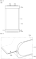
- Fig. 4 is a view illustrating the electrode assembly 110 accommodated in the exterior material 140 according to an embodiment.
- Fig. 5 is a view illustrating the exterior material 140 and the cover member 120b combined with each other.
- Fig. 5 is a sectional perspective view taken along line B-B' of Fig. 4 , where Fig. 5 illustrates a coupling structure of the exterior material 140 and the cover member 120b.
- a battery 100 may include the exterior material 140 that accommodates the electrode assembly 110 and the at least one cover member 120a and/or 120b described above.
- the exterior material 140 may include a pouch type (two halves sealed together at the edges, forming an interior space or "pouch") exterior material 140 having a plurality of film sheets and metal sheets laminated one above another.
- the film sheets may include, for example, an insulating resin (e.g., polypropylene, nylon, or the like), and the metal sheets may include, for example, an aluminum sheet.
- the exterior material 140 of a pouch type is illustrated in Figs. 4 and 5
- the battery 100 according to the embodiment may include an exterior material in the shape of a prism, a cylinder, or a coin, other than the pouch type exterior material.
- the exterior material 140 may include a first laminated structure 140a disposed above the electrode assembly 110 and a second laminated structure 140b disposed below the electrode assembly 110.
- the first and second laminated structures 140a and 140b may be bonded by a thermal-curing or photo-curing process (e.g., a curing process at a temperature of 180°C and a pressure of 0.8 MPa for 3.0 sec) to seal the inner space in which the electrode assembly 110 and the at least one cover member 120a and/or 120b are accommodated.
- a thermal-curing or photo-curing process e.g., a curing process at a temperature of 180°C and a pressure of 0.8 MPa for 3.0 sec
- Fig. 6 is an exploded perspective view illustrating an electronic device 1000 according to an embodiment.
- the electronic device 1000 may include a first case 200 (e.g., a rear case), a second case 300 (e.g., a front case), a display 400, a printed circuit board 500, and the battery 100.
- the electronic device 1000 may not include at least one of the components mentioned above, or may further include other component(s).
- the electronic device 1000 may further include at least one system resource (e.g., a processor and/or a memory) that supports operation of a function (e.g., contents output) of the display 400 or is powered by the battery 100.
- a system resource e.g., a processor and/or a memory
- the first case 200 and the second case 300 may be combined together to form a housing for accommodating the components of the electronic device 1000.
- at least one protruding member may be formed on at least a partial area (e.g., an edge area) of any one of the first and second cases 200 and 300, and at least one receiving member corresponding to the shape of the protruding member may be formed on at least a partial area (e.g., an edge area) of the other case.
- the protruding member may be fit into the receiving member by external pressure.
- the first case 200 and the second case 300 may be integrally coupled to each other.
- the second case 300 may include a first surface 10 and one or more second surfaces 20 extending from the edge of the first surface 10 at a specified angle (e.g., substantially 90 degrees) in third and fourth directions.
- the one or more second surfaces 20 may be separately formed and then fastened (or coupled) with each other, or may be integrally formed with each other.
- the second case 300 may include a first internal space that is open in the third direction and a second internal space that is open in the fourth direction, depending on the structural shape by the first surface 10 and the second surfaces 20.
- the second case 300 may include, in a region of the first internal space, a frame structure 310 for accommodating the battery 100.
- the frame structure 310 may be formed through a separate process and then coupled (or bonded) to the second case 300, or may be formed as part of the second case 300 in the manufacturing process (e.g., injection molding) of the second case 300.
- the frame structure 310 may include a first surface 30 (e.g., a base or a surface on which the battery 100 is placed) and one or more second surfaces 40 (e.g., side surfaces or surfaces by which the battery 100 is fixed) that extend from the edge of the first surface 30 at a specified angle (e.g., substantially 90 degrees).
- the second surfaces 40 of the frame structure 310 may extend from the first surface 30 to the height that is equal or similar to the thickness of the battery 100.
- the display 400 may be disposed in the second internal space of the second case 300. For example, part of the display 400 may be inserted into the second internal space, and the remaining part of the display 400 may be exposed to the outside and may be coupled (or bonded) to the distal ends of the second surfaces 40 of the second case 300, which form the second internal space, to finish the open second internal space.
- the display 400 may include a touch screen display.
- the display 400 may include a display panel, a cover glass, and a touch panel (or a touch sensor).
- the display panel may output at least one user interface or contents (e.g., text, an image, a video, an icon, a widget, a symbol, or the like) in response to a user input or preset scheduling information.
- the cover glass may be disposed above the display panel and may transmit light emitted from the display panel.
- a user input e.g., a touch, a drag, a press, or the like
- a user's body e.g., a finger
- an electronic pen may be applied to at least a partial area of the cover glass.
- the touch panel may receive a signal according to the user input and may output an electrical signal corresponding thereto (e.g., a capacitive type, a pressure sensitive type, an infrared type, or an ultrasonic type).
- At least one component related to operation of a function of the electronic device 1000 may be mounted on the printed circuit board 500.
- a memory, a processor, an antenna module, a speaker module, or a conductive circuit related to the components may be mounted on the printed circuit board 500.
- the printed circuit board 500 may be formed in a shape avoiding the frame structure 310 so as not to overlap at least a partial area of the battery 100 accommodated in the frame structure 310.
- a plurality of printed circuit boards 500 may be provided, and at least some of the plurality of printed circuit boards 500 may be electrically connected together and may be laminated one above another.
- the battery 100 may be understood as a battery that includes the electrode assembly, the cover member, and the exterior material that have been described above with reference to Figs. 1 to 5 .
- the battery 100 may be fixed in the frame structure 310 by an adhesive member 600 (e.g., a tape) with an area the same as or corresponding to that of the battery 100.
- the battery 100 may be electrically connected to the components of the electronic device 1000 to supply drive power thereto.
- a protection circuit module PCM
- the protection circuit module may prevent over-charge or over-discharge of the battery 100.
- an over-charge protection voltage value or an over-discharge protection voltage value may be set for the protection circuit module.
- the battery 100 may include a lithium ion battery or a lithium ion polymer battery.
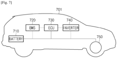
- Fig. 7 is a view illustrating an electric vehicle to which a battery according to an embodiment is applicable.
- the battery described above with reference to Figs. 1 to 5 may be applied to various aspects of electric vehicles (e.g., a battery electric vehicle, a hybrid electric vehicle, a plug-in hybrid electric vehicle, or the like), in addition to the electronic device 1000 (see Fig. 6 ).
- electric vehicles e.g., a battery electric vehicle, a hybrid electric vehicle, a plug-in hybrid electric vehicle, or the like
- an electric vehicle 701 may include a battery 710, a battery management system (BMS) 720, an electric control unit (ECU) 730, an inverter 740, and a motor 750.
- BMS battery management system
- ECU electric control unit
- the battery 710 may include the electrode assembly 110 (see Fig. 4 ), the at least one cover member 120a and/or 120b (see Fig. 4 ), and the exterior material 140 (see Fig. 4 ) that have been described above.
- the battery 710 may supply power to the motor 750 to drive the electric vehicle 701 and may be charged or discharged by the inverter 740 according to operation of the motor 750 or an internal combustion engine (not illustrated).
- the BMS 720 may estimate status information such as the state of charging, the state of health, the maximum allowable input/output power, or the output voltage of the battery 710 and may control over-charge or over-discharge of the battery 710 using the status information.
- the ECU 730 may be an electronic control device that controls the state of the electric vehicle 701.
- the ECU 730 may determine torque based on vehicle information such as an accelerator, a brake, or speed and may control the motor 750 such that the output of the motor 750 corresponds to the torque information.
- the inverter 740 may receive a charge or discharge control signal of the battery 710 from the ECU 730 and may control the battery 710.
- the motor 750 may drive the electric vehicle 701, based on power (e.g., electrical energy) supplied from the battery 710 or control information transferred from the ECU 730.
- the battery 710 may supply power to another component mounted in the electric vehicle 701.
- the battery 710 may supply power to a central information display for displaying various types of contents related to driving of the electric vehicle 701, a navigation system, a cluster, or the like.
- the battery 710 may supply power to a communication module that supports communication between the electric vehicle 701 and an external device or an external server, or a sensor module that performs various sensing operations on the inside or the outside of the electric vehicle 701.
- a battery may include an electrode assembly including a positive electrode sheet, a separation membrane, and a negative electrode sheet, at least one cover member surrounding at least a part of an outermost region of the electrode assembly, and exterior material accommodating the electrode assembly and the at least one cover member.
- at least one cover member has at least a partial area that overlaps and is fixed to the exterior material, and includes a plurality of air gaps permitting impregnation of the electrode assembly by an electrolyte.
- the at least one cover member may include a plurality of air gaps that support impregnation of an electrolyte into the electrode assembly.
- the at least one cover member may be formed to surround at least one of a distal end of the electrode assembly in a first direction or a distal end of the electrode assembly in a second direction.
- the plurality of air gaps may include a regular or irregular pattern.
- the battery may further include at least one electrode tab protruding from the electrode assembly.
- the plurality of air gaps may be formed in a region corresponding to a protruding region of the electrode tab.
- the plurality of air gaps may be formed to avoid the protruding region of the electrode tab.
- the at least one cover member may include polypropylene.
- the electrode assembly may include a jelly-roll type electrode assembly in which the positive electrode sheet, the separation membrane, and the negative electrode sheet laminated one above another are spirally wound.
- the exterior material may include a pouch type exterior material having a plurality of film sheets and metal sheets laminated one above another.
- the exterior material may include a first laminated structure disposed above the electrode assembly and a second laminated structure disposed below the electrode assembly.
- the at least a partial area of the at least one cover member may overlap at least part of facing regions of the first laminated structure and the second laminated structure.
- the at least a partial area of the at least one cover member may be cured with the first laminated structure and the second laminated structure and may be fixed to the exterior material.
- An electronic device may include a housing, a display accommodated in the housing and having at least part exposed outside the housing, a memory accommodated in the housing, a battery accommodated in the housing, and a processor electrically connected to the display, the memory, and the battery.
- the battery included in the electronic device may include an electrode assembly include an electrode assembly including a positive electrode sheet, a separation membrane, and a negative electrode sheet, at least one cover member surrounding at least a part of an outermost region of the electrode assembly, and exterior material accommodating the electrode assembly and the at least one cover member.
- the at least one cover member has at least a partial area that overlaps and is fixed to the exterior material, and includes a plurality of air gaps permitting impregnation of the electrode assembly by an electrolyte.
- the at least one cover member of the battery included in the electronic device may include a plurality of air gaps that support impregnation of an electrolyte into the electrode assembly.
- the at least one cover member of the battery included in the electronic device may be formed to surround at least one of a distal end of the electrode assembly in a first direction or a distal end of the electrode assembly in a second direction.
- the battery included in the electronic device may further include at least one electrode tab protruding from the electrode assembly.
- the plurality of air gaps of the battery included in the electronic device may be formed in a region corresponding to a protruding region of the electrode tab.
- the exterior material of the battery included in the electronic device may include a first laminated structure disposed above the electrode assembly and a second laminated structure disposed below the electrode assembly,
- the at least a partial area of the at least one cover member of the battery included in the electronic device may overlap at least part of facing regions of the first laminated structure and the second laminated structure.
- Fig. 8 is a block diagram of an electronic device in a network environment according to an embodiment.
- an electronic device 801 may communicate with an electronic device 802 through a first network 898 (e.g., a short-range wireless communication) or may communicate with an electronic device 804 or a server 808 through a second network 899 (e.g., a long-distance wireless communication) in a network environment 800.
- the electronic device 801 may communicate with the electronic device 804 through the server 808.
- the electronic device 801 may include a processor 820, a memory 830, an input device 850, a sound output device 855, a display device 860, an audio module 870, a sensor module 876, an interface 877, a haptic module 879, a camera module 880, a power management module 888, a battery 889, a communication module 890, a subscriber identification module 896, and an antenna module 897.
- at least one e.g., the display device 860 or the camera module 880
- components of the electronic device 801 may be omitted or other components may be added to the electronic device 801.
- some components may be integrated and implemented as in the case of the sensor module 876 (e.g., a fingerprint sensor, an iris sensor, or an illuminance sensor) embedded in the display device 860 (e.g., a display).
- the sensor module 876 e.g., a fingerprint sensor, an iris sensor, or an illuminance sensor
- the display device 860 e.g., a display
- the processor 820 may operate, for example, software (e.g., a program 840) to control at least one of other components (e.g., a hardware or software component) of the electronic device 801 connected to the processor 820 and may process and compute a variety of data.
- the processor 820 may load a command set or data, which is received from other components (e.g., the sensor module 876 or the communication module 890), into a volatile memory 832, may process the loaded command or data, and may store result data into a nonvolatile memory 834.
- the processor 820 may include a main processor 821 (e.g., a central processing unit or an application processor) and an auxiliary processor 823 (e.g., a graphic processing device, an image signal processor, a sensor hub processor, or a communication processor), which operates independently from the main processor 821, additionally or alternatively uses less power than the main processor 821, or is specified to a designated function.
- the auxiliary processor 823 may operate separately from the main processor 821 or embedded.
- the auxiliary processor 823 may control, for example, at least some of functions or states associated with at least one component (e.g., the display device 860, the sensor module 876, or the communication module 890) among the components of the electronic device 801 instead of the main processor 821 while the main processor 821 is in an inactive (e.g., sleep) state or together with the main processor 821 while the main processor 821 is in an active (e.g., an application execution) state.
- the auxiliary processor 823 e.g., the image signal processor or the communication processor
- the auxiliary processor 823 may be implemented as a part of another component (e.g., the camera module 880 or the communication module 890) that is functionally related to the auxiliary processor 823.
- the memory 830 may store a variety of data used by at least one component (e.g., the processor 820 or the sensor module 876) of the electronic device 801, for example, software (e.g., the program 840) and input data or output data with respect to commands associated with the software.
- the memory 830 may include the volatile memory 832 or the nonvolatile memory 834.
- the program 840 may be stored in the memory 830 as software and may include, for example, an operating system 842, a middleware 844, or an application 846.
- the input device 850 may be a device for receiving a command or data, which is used for a component (e.g., the processor 820) of the electronic device 801, from an outside (e.g., a user) of the electronic device 801 and may include, for example, a microphone, a mouse, or a keyboard.
- a component e.g., the processor 820
- the electronic device 801 may include, for example, a microphone, a mouse, or a keyboard.
- the sound output device 855 may be a device for outputting a sound signal to the outside of the electronic device 801 and may include, for example, a speaker used for general purposes, such as multimedia play or recordings play, and a receiver used only for receiving calls. According to an embodiment, the receiver and the speaker may be either integrally or separately implemented.
- the display device 860 may be a device for visually presenting information to the user and may include, for example, a display, a hologram device, or a projector and a control circuit for controlling a corresponding device. According to an embodiment, the display device 860 may include a touch circuitry or a pressure sensor for measuring an intensity of pressure on the touch.
- the audio module 870 may convert a sound and an electrical signal in dual directions. According to an embodiment, the audio module 870 may obtain the sound through the input device 850 or may output the sound through an external electronic device (e.g., the electronic device 802 (e.g., a speaker or a headphone)) wired or wirelessly connected to the sound output device 855 or the electronic device 801.
- an external electronic device e.g., the electronic device 802 (e.g., a speaker or a headphone)
- the sensor module 876 may generate an electrical signal or a data value corresponding to an operating state (e.g., power or temperature) inside or an environmental state outside the electronic device 801.
- the sensor module 876 may include, for example, a gesture sensor, a gyro sensor, a barometric pressure sensor, a magnetic sensor, an acceleration sensor, a grip sensor, a proximity sensor, a color sensor, an infrared sensor, a biometric sensor, a temperature sensor, a humidity sensor, or an illuminance sensor.
- the interface 877 may support a designated protocol wired or wirelessly connected to the external electronic device (e.g., the electronic device 802).
- the interface 877 may include, for example, an HDMI (high-definition multimedia interface), a USB (universal serial bus) interface, an SD card interface, or an audio interface.
- a connecting terminal 878 may include a connector that physically connects the electronic device 801 to the external electronic device (e.g., the electronic device 802), for example, an HDMI connector, a USB connector, an SD card connector, or an audio connector (e.g., a headphone connector).
- the external electronic device e.g., the electronic device 802
- an HDMI connector e.g., a USB connector
- SD card connector e.g., an SD card connector
- an audio connector e.g., a headphone connector
- the haptic module 879 may convert an electrical signal to a mechanical stimulation (e.g., vibration or movement) or an electrical stimulation perceived by the user through tactile or kinesthetic sensations.
- the haptic module 879 may include, for example, a motor, a piezoelectric element, or an electric stimulator.
- the camera module 880 may shoot a still image or a video image.
- the camera module 880 may include, for example, at least one lens, an image sensor, an image signal processor, or a flash.
- the power management module 888 may be a module for managing power supplied to the electronic device 801 and may serve as at least a part of a power management integrated circuit (PMIC).
- PMIC power management integrated circuit
- the battery 889 may be a device for supplying power to at least one component of the electronic device 801 and may include, for example, a non-rechargeable (primary) battery, a rechargeable (secondary) battery, or a fuel cell.
- the communication module 890 may establish a wired or wireless communication channel between the electronic device 801 and the external electronic device (e.g., the electronic device 802, the electronic device 804, or the server 808) and support communication execution through the established communication channel.
- the communication module 890 may include at least one communication processor operating independently from the processor 820 (e.g., the application processor) and supporting the wired communication or the wireless communication.
- the communication module 890 may include a wireless communication module 892 (e.g., a cellular communication module, a short-range wireless communication module, or a GNSS (global navigation satellite system) communication module) or a wired communication module 894 (e.g., an LAN (local area network) communication module or a power line communication module) and may communicate with the external electronic device using a corresponding communication module among them through the first network 898 (e.g., the short-range communication network such as a Bluetooth, a Wi-Fi direct, or an IrDA (infrared data association)) or the second network 899 (e.g., the long-distance wireless communication network such as a cellular network, an internet, or a computer network (e.g., LAN or WAN)).
- the above-mentioned various communication modules 890 may be implemented into one chip or into separate chips, respectively.
- the wireless communication module 892 may identify and authenticate the electronic device 801 using user information stored in the subscriber identification module 896 in the communication network.
- the antenna module 897 may include one or more antennas to transmit or receive the signal or power to or from an external source.
- the communication module 890 e.g., the wireless communication module 892
- Some components among the components may be connected to each other through a communication method (e.g., a bus, a GPIO (general purpose input/output), an SPI (serial peripheral interface), or an MIPI (mobile industry processor interface)) used between peripheral devices to exchange signals (e.g., a command or data) with each other.
- a communication method e.g., a bus, a GPIO (general purpose input/output), an SPI (serial peripheral interface), or an MIPI (mobile industry processor interface) used between peripheral devices to exchange signals (e.g., a command or data) with each other.
- the command or data may be transmitted or received between the electronic device 801 and the external electronic device 804 through the server 808 connected to the second network 899.
- Each of the electronic devices 802 and 804 may be the same or different types as or from the electronic device 801.
- all or some of the operations performed by the electronic device 801 may be performed by another electronic device or a plurality of external electronic devices.
- the electronic device 801 may request the external electronic device to perform at least some of the functions related to the functions or services, in addition to or instead of performing the functions or services by itself.
- the external electronic device receiving the request may carry out the requested function or the additional function and transmit the result to the electronic device 801.
- the electronic device 801 may provide the requested functions or services based on the received result as is or after additionally processing the received result.
- a cloud computing, distributed computing, or client-server computing technology may be used.
- the electronic device may be various types of devices.
- the electronic device may include, for example, at least one of a portable communication device (e.g., a smartphone), a computer device, a portable multimedia device, a mobile medical appliance, a camera, a wearable device, or a home appliance.
- a portable communication device e.g., a smartphone
- a computer device e.g
- module used herein may represent, for example, a unit including one or more combinations of hardware, software and firmware.
- module may be interchangeably used with the terms “logic”, “logical block”, “part” and “circuit”.
- the “module” may be a minimum unit of an integrated part or may be a part thereof.
- the “module” may be a minimum unit for performing one or more functions or a part thereof.
- the “module” may include an application-specific integrated circuit (ASIC).
- ASIC application-specific integrated circuit
- Various embodiments of the present disclosure may be implemented by software (e.g., the program 840) including an instruction stored in a machine-readable storage media (e.g., an internal memory 836 or an external memory 838) readable by a machine (e.g., a computer).
- the machine may be a device that calls the instruction from the machine-readable storage media and operates depending on the called instruction and may include the electronic device (e.g., the electronic device 801).
- the processor e.g., the processor 820
- the processor may perform a function corresponding to the instruction directly or using other components under the control of the processor.
- the instruction may include a code generated or executed by a compiler or an interpreter.
- the machine-readable storage media may be provided in the form of non-transitory storage media.
- non-transitory is a limitation of the medium itself (i.e., tangible, not a signal) as opposed to a limitation on data storage persistency.
- the method according to various embodiments disclosed in the present disclosure may be provided as a part of a computer program product.
- the computer program product may be traded between a seller and a buyer as a product.
- the computer program product may be distributed in the form of machine-readable storage medium (e.g., a compact disc read only memory (CD-ROM)) or may be distributed only through an application store (e.g., a Play Store TM ).
- an application store e.g., a Play Store TM
- at least a portion of the computer program product may be temporarily stored or generated in a storage medium such as a memory of a manufacturer's server, an application store's server, or a relay server.
- Each component may include at least one of the above components, and a portion of the above sub-components may be omitted, or additional other sub-components may be further included.
- some components e.g., the module or the program
- Operations performed by a module, a programming, or other components according to various embodiments of the present disclosure may be executed sequentially, in parallel, repeatedly, or in a heuristic method. Also, at least some operations may be executed in different sequences, omitted, or other operations may be added.
Landscapes
- Engineering & Computer Science (AREA)
- Chemical & Material Sciences (AREA)
- General Chemical & Material Sciences (AREA)
- Electrochemistry (AREA)
- Chemical Kinetics & Catalysis (AREA)
- Theoretical Computer Science (AREA)
- Computer Hardware Design (AREA)
- Manufacturing & Machinery (AREA)
- General Physics & Mathematics (AREA)
- General Engineering & Computer Science (AREA)
- Physics & Mathematics (AREA)
- Human Computer Interaction (AREA)
- Power Engineering (AREA)
- Materials Engineering (AREA)
- Sealing Battery Cases Or Jackets (AREA)
- Battery Mounting, Suspending (AREA)
Claims (15)
- Batterie (100; 710), umfassend:eine Elektrodenanordnung (110), die eine positive Elektrodenplatte (111), eine Trennmembran (112) und eine negative Elektrodenplatte (113) enthält;mindestens ein Abdeckelement (120; 120a, 120b), das mindestens einen Teil eines äußersten Bereichs der Elektrodenanordnung (110) umgibt; undAußenmaterial (140), das die Elektrodenanordnung (110) und das mindestens eine Abdeckelement (120; 120a, 120b) aufnimmt,wobei das mindestens eine Abdeckelement (120; 120a, 120b) mindestens einen Teilbereich aufweist, der das Außenmaterial (140) überlappt und daran befestigt ist, und eine Vielzahl von Luftspalten (121) enthält, die eine Durchtränkung der Elektrodenanordnung durch einen Elektrolyten ermöglichen.
- Batterie nach Anspruch 1, wobei das mindestens eine Abdeckelement (120; 120a, 120b) so ausgebildet ist, dass es mindestens eines von einem distalen Ende der Elektrodenanordnung (110) in einer ersten Richtung oder einem distalen Ende der Elektrodenanordnung (110) in einer zweiten Richtung umgibt.
- Batterie nach Anspruch 1, wobei die Vielzahl von Luftspalten (121) ein regelmäßiges Muster enthalten.
- Batterie nach Anspruch 1, ferner umfassend:mindestens einen Elektrodenstreifen (130), der von der Elektrodenanordnung (110) hervorsteht,wobei die Vielzahl von Luftspalten (121) in einem Bereich ausgebildet sind, der einem hervorstehenden Bereich des Elektrodenstreifens (130) entspricht.
- Batterie nach Anspruch 4, wobei die Vielzahl von Luftspalten (121) den hervorstehenden Bereich des Elektrodenstreifens (130) meiden.
- Batterie nach Anspruch 1, wobei das mindestens eine Abdeckelement (120; 120a, 120b) Polypropylen umfasst.
- Batterie nach Anspruch 1, wobei die positive Elektrodenplatte (111), die Trennmembran (112) und die negative Elektrodenplatte (113) übereinander geschichtet und spiralförmig gewickelt sind.
- Batterie nach Anspruch 1, wobei das Außenmaterial (140) ein beutelartiges Außenmaterial enthält, das eine Vielzahl von Folienplatten und Metallplatten aufweist, die übereinander geschichtet sind.
- Batterie nach Anspruch 1, wobei das Außenmaterial (140) eine erste geschichtete Struktur (140a), die über der Elektrodenanordnung (110) angeordnet ist, und eine zweite geschichtete Struktur (140b), die unter der Elektrodenanordnung (110) angeordnet ist, enthält.
- Batterie nach Anspruch 9, wobei der mindestens eine Teilbereich des mindestens einen Abdeckelements (120; 120a, 120b) mindestens einen Teil einander zugewandter Bereiche der ersten geschichteten Struktur (140a) und der zweiten geschichteten Struktur (140b) überlappt.
- Batterie nach Anspruch 9, wobei der mindestens eine Teilbereich des mindestens einen Abdeckelements (120; 120a, 120b) mit der ersten geschichteten Struktur (140a) und der zweiten geschichteten Struktur (140b) gehärtet und an dem Außenmaterial (140) befestigt ist.
- Batterie nach Anspruch 1, wobei die Vielzahl von Luftspalten (121) ein unregelmäßiges Muster enthalten.
- Elektronische Vorrichtung (1000), umfassend:ein Gehäuse (200, 300);eine Anzeige (400; 860), die in dem Gehäuse aufgenommen ist, wobei mindestens ein Teil der Anzeige außerhalb des Gehäuses freiliegt;einen Speicher (830), der in dem Gehäuse angeordnet ist;eine Batterie (100; 889), die in dem Gehäuse aufgenommen ist; undeinen Prozessor (820), der elektrisch mit der Anzeige (400; 860), dem Speicher (830) und der Batterie (100; 889) verbunden ist,wobei die Batterie Folgendes enthält:eine Elektrodenanordnung (110), die eine positive Elektrodenplatte (111), eine Trennmembran (112) und eine negative Elektrodenplatte (113) enthält;mindestens ein Abdeckelement (120; 120a, 120b), das mindestens einen Teil eines äußersten Bereichs der Elektrodenanordnung umgibt; undein Außenmaterial (140), das die Elektrodenanordnung (110) und das mindestens eine Abdeckelement (120; 120a, 120b) aufnimmt, undwobei das mindestens eine Abdeckelement (120; 120a, 120b) mindestens einen Teilbereich aufweist, der das Außenmaterial (140) überlappt und der an dem Außenmaterial befestigt ist, und eine Vielzahl von Luftspalten (121) enthält, die eine Durchtränkung der Elektrodenanordnung (110) durch einen Elektrolyten unterstützen.
- Elektronische Vorrichtung nach Anspruch 13, wobei das mindestens eine Abdeckelement (120; 120a, 120b) mindestens eines von einem distalen Ende der Elektrodenanordnung (110) in einer ersten Richtung oder einem distalen Ende der Elektrodenanordnung (110) in einer zweiten Richtung umgibt.
- Elektronische Vorrichtung nach Anspruch 13, wobei die Batterie ferner mindestens einen Elektrodenstreifen (130) enthält, der von der Elektrodenanordnung (110) hervorsteht, und
wobei die Vielzahl von Luftspalten (121) in einem Bereich ausgebildet sind, der einem hervorstehenden Bereich des Elektrodenstreifens (130) entspricht.
Applications Claiming Priority (2)
| Application Number | Priority Date | Filing Date | Title |
|---|---|---|---|
| KR1020170140171A KR102576645B1 (ko) | 2017-10-26 | 2017-10-26 | 배터리 및 이를 포함하는 전자 장치 |
| PCT/KR2018/012741 WO2019083303A1 (en) | 2017-10-26 | 2018-10-25 | BATTERY AND ELECTRONIC DEVICE COMPRISING SAME |
Publications (3)
| Publication Number | Publication Date |
|---|---|
| EP3673530A1 EP3673530A1 (de) | 2020-07-01 |
| EP3673530A4 EP3673530A4 (de) | 2020-11-18 |
| EP3673530B1 true EP3673530B1 (de) | 2023-11-29 |
Family
ID=66244328
Family Applications (1)
| Application Number | Title | Priority Date | Filing Date |
|---|---|---|---|
| EP18871194.9A Active EP3673530B1 (de) | 2017-10-26 | 2018-10-25 | Batterie und elektronische vorrichtung damit |
Country Status (4)
| Country | Link |
|---|---|
| US (1) | US10862080B2 (de) |
| EP (1) | EP3673530B1 (de) |
| KR (1) | KR102576645B1 (de) |
| WO (1) | WO2019083303A1 (de) |
Families Citing this family (7)
| Publication number | Priority date | Publication date | Assignee | Title |
|---|---|---|---|---|
| CN111509286B (zh) * | 2019-01-31 | 2021-10-22 | 东莞新能安科技有限公司 | 电芯及电池 |
| KR102808772B1 (ko) * | 2019-10-18 | 2025-05-16 | 주식회사 엘지에너지솔루션 | 차량 배터리 화재 감지 장치 및 감지 방법 |
| CN113764789B (zh) | 2020-05-18 | 2023-04-07 | 比亚迪股份有限公司 | 一种电池、电池包及汽车 |
| CN114171840B (zh) * | 2020-08-19 | 2023-07-14 | 比亚迪股份有限公司 | 电池、电池模组、电池包及电动车 |
| WO2022193879A1 (zh) * | 2021-03-17 | 2022-09-22 | 东莞新能安科技有限公司 | 电化学装置、电池包及用电装置 |
| KR20220141122A (ko) * | 2021-04-12 | 2022-10-19 | 삼성전자주식회사 | 보호 테이프를 포함하는 배터리 및 이를 포함하는 전자 장치 |
| WO2026024047A1 (ko) * | 2024-07-22 | 2026-01-29 | 삼성전자 주식회사 | 배터리 및 이를 포함하는 전자 장치 |
Family Cites Families (11)
| Publication number | Priority date | Publication date | Assignee | Title |
|---|---|---|---|---|
| JPH10241744A (ja) | 1997-02-25 | 1998-09-11 | Japan Storage Battery Co Ltd | 非水電解質二次電池 |
| JP4424053B2 (ja) * | 2004-04-28 | 2010-03-03 | トヨタ自動車株式会社 | ラミネート型二次電池、およびその組電池 |
| JP5252937B2 (ja) * | 2008-01-31 | 2013-07-31 | 三洋電機株式会社 | 積層式電池及びその製造方法 |
| WO2009113470A1 (ja) | 2008-03-14 | 2009-09-17 | 日本電気株式会社 | 被覆材及びフィルム外装電気デバイス |
| KR101101079B1 (ko) * | 2010-04-05 | 2011-12-30 | 삼성에스디아이 주식회사 | 이차전지 |
| EP2477252B1 (de) | 2010-10-04 | 2020-08-19 | LG Chem, Ltd. | Dichtungsband und sekundärbatterie damit |
| CN104067416B (zh) | 2012-01-27 | 2016-08-17 | 丰田自动车株式会社 | 密闭型电池 |
| KR20140032712A (ko) * | 2012-09-07 | 2014-03-17 | 주식회사 엘지화학 | 이차전지 |
| WO2015102442A1 (ko) | 2014-01-06 | 2015-07-09 | 주식회사 엘지화학 | 플렉서블 전지셀 |
| KR101772732B1 (ko) * | 2014-04-04 | 2017-08-29 | 주식회사 엘지화학 | 이차전지 |
| KR102479486B1 (ko) * | 2015-10-28 | 2022-12-19 | 삼성에스디아이 주식회사 | 파우치형 이차 전지 |
-
2017
- 2017-10-26 KR KR1020170140171A patent/KR102576645B1/ko active Active
-
2018
- 2018-10-25 US US16/170,241 patent/US10862080B2/en not_active Expired - Fee Related
- 2018-10-25 EP EP18871194.9A patent/EP3673530B1/de active Active
- 2018-10-25 WO PCT/KR2018/012741 patent/WO2019083303A1/en not_active Ceased
Also Published As
| Publication number | Publication date |
|---|---|
| US10862080B2 (en) | 2020-12-08 |
| WO2019083303A1 (en) | 2019-05-02 |
| EP3673530A4 (de) | 2020-11-18 |
| EP3673530A1 (de) | 2020-07-01 |
| KR20190046404A (ko) | 2019-05-07 |
| KR102576645B1 (ko) | 2023-09-11 |
| US20190131594A1 (en) | 2019-05-02 |
Similar Documents
| Publication | Publication Date | Title |
|---|---|---|
| EP3673530B1 (de) | Batterie und elektronische vorrichtung damit | |
| KR102389704B1 (ko) | 무선 전력 송수신 도전성 패턴을 구비한 전자 장치 | |
| CN110140340B (zh) | 电池的保护电路模块外壳及包括所述外壳的电子装置 | |
| EP3079033B1 (de) | Elektronische vorrichtung mit bildschirm | |
| US20170357214A1 (en) | Strap and electronic device including the same | |
| US20180364759A1 (en) | Display device and electronic device having same | |
| CN105892570A (zh) | 包括具有弯曲区域的显示器的电子设备 | |
| KR102582586B1 (ko) | 무지부의 적어도 일부에 노치가 형성된 배터리를 포함하는 전자 장치 | |
| CN110088972B (zh) | 涂覆电池活性材料的方法和具有该电池的电子装置 | |
| US20210234203A1 (en) | Battery and electronic device comprising same | |
| EP3964925B1 (de) | Elektronische vorrichtung mit mehreren batterien | |
| KR20200017291A (ko) | 배터리 및 이를 포함하는 전자 장치 | |
| KR102899635B1 (ko) | 파우치형 배터리를 포함하는 전자 장치 | |
| KR20190138972A (ko) | 전극 탭들을 구비한 배터리 및 이를 구비한 전자 장치 | |
| KR20200019411A (ko) | 배터리 접착 구조 및 이를 포함하는 전자 장치 | |
| KR102848290B1 (ko) | 배터리 및 그를 포함하는 전자 장치 | |
| EP3701582B1 (de) | Batterie und elektronische vorrichtung damit | |
| EP3726821B1 (de) | Elektronische vorrichtung mit einem verbinder mit gestapelter struktur | |
| EP3477760B1 (de) | Elektronische vorrichtung mit einer batterie | |
| KR20180053160A (ko) | 배터리를 포함하는 전자 장치 | |
| US9620914B2 (en) | Electronic device | |
| KR20230026730A (ko) | 배터리를 포함하는 전자 장치 | |
| US12603285B2 (en) | Battery including electrode assembly and electronic device including the same |
Legal Events
| Date | Code | Title | Description |
|---|---|---|---|
| STAA | Information on the status of an ep patent application or granted ep patent |
Free format text: STATUS: THE INTERNATIONAL PUBLICATION HAS BEEN MADE |
|
| PUAI | Public reference made under article 153(3) epc to a published international application that has entered the european phase |
Free format text: ORIGINAL CODE: 0009012 |
|
| STAA | Information on the status of an ep patent application or granted ep patent |
Free format text: STATUS: REQUEST FOR EXAMINATION WAS MADE |
|
| 17P | Request for examination filed |
Effective date: 20200327 |
|
| AK | Designated contracting states |
Kind code of ref document: A1 Designated state(s): AL AT BE BG CH CY CZ DE DK EE ES FI FR GB GR HR HU IE IS IT LI LT LU LV MC MK MT NL NO PL PT RO RS SE SI SK SM TR |
|
| AX | Request for extension of the european patent |
Extension state: BA ME |
|
| A4 | Supplementary search report drawn up and despatched |
Effective date: 20201015 |
|
| RIC1 | Information provided on ipc code assigned before grant |
Ipc: H01M 2/26 20060101ALI20201009BHEP Ipc: H01M 10/058 20100101ALI20201009BHEP Ipc: H01M 2/02 20060101ALI20201009BHEP Ipc: H01M 10/04 20060101AFI20201009BHEP Ipc: H01M 10/0587 20100101ALI20201009BHEP |
|
| DAV | Request for validation of the european patent (deleted) | ||
| DAX | Request for extension of the european patent (deleted) | ||
| REG | Reference to a national code |
Ref legal event code: R079 Ref country code: DE Ref legal event code: R079 Ref document number: 602018061999 Country of ref document: DE Free format text: PREVIOUS MAIN CLASS: H01M0010040000 Ipc: H01M0050116000 |
|
| GRAP | Despatch of communication of intention to grant a patent |
Free format text: ORIGINAL CODE: EPIDOSNIGR1 |
|
| STAA | Information on the status of an ep patent application or granted ep patent |
Free format text: STATUS: GRANT OF PATENT IS INTENDED |
|
| RIC1 | Information provided on ipc code assigned before grant |
Ipc: H01M 10/0587 20100101ALI20230428BHEP Ipc: H01M 10/058 20100101ALI20230428BHEP Ipc: H01M 4/04 20060101ALI20230428BHEP Ipc: H01M 50/60 20210101ALI20230428BHEP Ipc: H01M 50/557 20210101ALI20230428BHEP Ipc: H01M 50/543 20210101ALI20230428BHEP Ipc: H01M 50/124 20210101ALI20230428BHEP Ipc: H01M 50/116 20210101AFI20230428BHEP |
|
| INTG | Intention to grant announced |
Effective date: 20230601 |
|
| GRAS | Grant fee paid |
Free format text: ORIGINAL CODE: EPIDOSNIGR3 |
|
| GRAA | (expected) grant |
Free format text: ORIGINAL CODE: 0009210 |
|
| STAA | Information on the status of an ep patent application or granted ep patent |
Free format text: STATUS: THE PATENT HAS BEEN GRANTED |
|
| AK | Designated contracting states |
Kind code of ref document: B1 Designated state(s): AL AT BE BG CH CY CZ DE DK EE ES FI FR GB GR HR HU IE IS IT LI LT LU LV MC MK MT NL NO PL PT RO RS SE SI SK SM TR |
|
| REG | Reference to a national code |
Ref country code: GB Ref legal event code: FG4D |
|
| REG | Reference to a national code |
Ref country code: CH Ref legal event code: EP |
|
| REG | Reference to a national code |
Ref country code: DE Ref legal event code: R096 Ref document number: 602018061999 Country of ref document: DE |
|
| REG | Reference to a national code |
Ref country code: IE Ref legal event code: FG4D |
|
| REG | Reference to a national code |
Ref country code: LT Ref legal event code: MG9D |
|
| REG | Reference to a national code |
Ref country code: NL Ref legal event code: MP Effective date: 20231129 |
|
| PG25 | Lapsed in a contracting state [announced via postgrant information from national office to epo] |
Ref country code: GR Free format text: LAPSE BECAUSE OF FAILURE TO SUBMIT A TRANSLATION OF THE DESCRIPTION OR TO PAY THE FEE WITHIN THE PRESCRIBED TIME-LIMIT Effective date: 20240301 |
|
| PG25 | Lapsed in a contracting state [announced via postgrant information from national office to epo] |
Ref country code: IS Free format text: LAPSE BECAUSE OF FAILURE TO SUBMIT A TRANSLATION OF THE DESCRIPTION OR TO PAY THE FEE WITHIN THE PRESCRIBED TIME-LIMIT Effective date: 20240329 |
|
| PG25 | Lapsed in a contracting state [announced via postgrant information from national office to epo] |
Ref country code: LT Free format text: LAPSE BECAUSE OF FAILURE TO SUBMIT A TRANSLATION OF THE DESCRIPTION OR TO PAY THE FEE WITHIN THE PRESCRIBED TIME-LIMIT Effective date: 20231129 |
|
| PG25 | Lapsed in a contracting state [announced via postgrant information from national office to epo] |
Ref country code: ES Free format text: LAPSE BECAUSE OF FAILURE TO SUBMIT A TRANSLATION OF THE DESCRIPTION OR TO PAY THE FEE WITHIN THE PRESCRIBED TIME-LIMIT Effective date: 20231129 |
|
| PG25 | Lapsed in a contracting state [announced via postgrant information from national office to epo] |
Ref country code: LT Free format text: LAPSE BECAUSE OF FAILURE TO SUBMIT A TRANSLATION OF THE DESCRIPTION OR TO PAY THE FEE WITHIN THE PRESCRIBED TIME-LIMIT Effective date: 20231129 Ref country code: IS Free format text: LAPSE BECAUSE OF FAILURE TO SUBMIT A TRANSLATION OF THE DESCRIPTION OR TO PAY THE FEE WITHIN THE PRESCRIBED TIME-LIMIT Effective date: 20240329 Ref country code: GR Free format text: LAPSE BECAUSE OF FAILURE TO SUBMIT A TRANSLATION OF THE DESCRIPTION OR TO PAY THE FEE WITHIN THE PRESCRIBED TIME-LIMIT Effective date: 20240301 Ref country code: ES Free format text: LAPSE BECAUSE OF FAILURE TO SUBMIT A TRANSLATION OF THE DESCRIPTION OR TO PAY THE FEE WITHIN THE PRESCRIBED TIME-LIMIT Effective date: 20231129 Ref country code: BG Free format text: LAPSE BECAUSE OF FAILURE TO SUBMIT A TRANSLATION OF THE DESCRIPTION OR TO PAY THE FEE WITHIN THE PRESCRIBED TIME-LIMIT Effective date: 20240229 |
|
| REG | Reference to a national code |
Ref country code: AT Ref legal event code: MK05 Ref document number: 1637065 Country of ref document: AT Kind code of ref document: T Effective date: 20231129 |
|
| PG25 | Lapsed in a contracting state [announced via postgrant information from national office to epo] |
Ref country code: NL Free format text: LAPSE BECAUSE OF FAILURE TO SUBMIT A TRANSLATION OF THE DESCRIPTION OR TO PAY THE FEE WITHIN THE PRESCRIBED TIME-LIMIT Effective date: 20231129 |
|
| PG25 | Lapsed in a contracting state [announced via postgrant information from national office to epo] |
Ref country code: SE Free format text: LAPSE BECAUSE OF FAILURE TO SUBMIT A TRANSLATION OF THE DESCRIPTION OR TO PAY THE FEE WITHIN THE PRESCRIBED TIME-LIMIT Effective date: 20231129 Ref country code: RS Free format text: LAPSE BECAUSE OF FAILURE TO SUBMIT A TRANSLATION OF THE DESCRIPTION OR TO PAY THE FEE WITHIN THE PRESCRIBED TIME-LIMIT Effective date: 20231129 Ref country code: PL Free format text: LAPSE BECAUSE OF FAILURE TO SUBMIT A TRANSLATION OF THE DESCRIPTION OR TO PAY THE FEE WITHIN THE PRESCRIBED TIME-LIMIT Effective date: 20231129 Ref country code: NO Free format text: LAPSE BECAUSE OF FAILURE TO SUBMIT A TRANSLATION OF THE DESCRIPTION OR TO PAY THE FEE WITHIN THE PRESCRIBED TIME-LIMIT Effective date: 20240229 Ref country code: NL Free format text: LAPSE BECAUSE OF FAILURE TO SUBMIT A TRANSLATION OF THE DESCRIPTION OR TO PAY THE FEE WITHIN THE PRESCRIBED TIME-LIMIT Effective date: 20231129 Ref country code: LV Free format text: LAPSE BECAUSE OF FAILURE TO SUBMIT A TRANSLATION OF THE DESCRIPTION OR TO PAY THE FEE WITHIN THE PRESCRIBED TIME-LIMIT Effective date: 20231129 Ref country code: HR Free format text: LAPSE BECAUSE OF FAILURE TO SUBMIT A TRANSLATION OF THE DESCRIPTION OR TO PAY THE FEE WITHIN THE PRESCRIBED TIME-LIMIT Effective date: 20231129 |
|
| PG25 | Lapsed in a contracting state [announced via postgrant information from national office to epo] |
Ref country code: DK Free format text: LAPSE BECAUSE OF FAILURE TO SUBMIT A TRANSLATION OF THE DESCRIPTION OR TO PAY THE FEE WITHIN THE PRESCRIBED TIME-LIMIT Effective date: 20231129 |
|
| PG25 | Lapsed in a contracting state [announced via postgrant information from national office to epo] |
Ref country code: AT Free format text: LAPSE BECAUSE OF FAILURE TO SUBMIT A TRANSLATION OF THE DESCRIPTION OR TO PAY THE FEE WITHIN THE PRESCRIBED TIME-LIMIT Effective date: 20231129 Ref country code: CZ Free format text: LAPSE BECAUSE OF FAILURE TO SUBMIT A TRANSLATION OF THE DESCRIPTION OR TO PAY THE FEE WITHIN THE PRESCRIBED TIME-LIMIT Effective date: 20231129 |
|
| PG25 | Lapsed in a contracting state [announced via postgrant information from national office to epo] |
Ref country code: SK Free format text: LAPSE BECAUSE OF FAILURE TO SUBMIT A TRANSLATION OF THE DESCRIPTION OR TO PAY THE FEE WITHIN THE PRESCRIBED TIME-LIMIT Effective date: 20231129 |
|
| PG25 | Lapsed in a contracting state [announced via postgrant information from national office to epo] |
Ref country code: SM Free format text: LAPSE BECAUSE OF FAILURE TO SUBMIT A TRANSLATION OF THE DESCRIPTION OR TO PAY THE FEE WITHIN THE PRESCRIBED TIME-LIMIT Effective date: 20231129 Ref country code: SK Free format text: LAPSE BECAUSE OF FAILURE TO SUBMIT A TRANSLATION OF THE DESCRIPTION OR TO PAY THE FEE WITHIN THE PRESCRIBED TIME-LIMIT Effective date: 20231129 Ref country code: RO Free format text: LAPSE BECAUSE OF FAILURE TO SUBMIT A TRANSLATION OF THE DESCRIPTION OR TO PAY THE FEE WITHIN THE PRESCRIBED TIME-LIMIT Effective date: 20231129 Ref country code: IT Free format text: LAPSE BECAUSE OF FAILURE TO SUBMIT A TRANSLATION OF THE DESCRIPTION OR TO PAY THE FEE WITHIN THE PRESCRIBED TIME-LIMIT Effective date: 20231129 Ref country code: EE Free format text: LAPSE BECAUSE OF FAILURE TO SUBMIT A TRANSLATION OF THE DESCRIPTION OR TO PAY THE FEE WITHIN THE PRESCRIBED TIME-LIMIT Effective date: 20231129 Ref country code: DK Free format text: LAPSE BECAUSE OF FAILURE TO SUBMIT A TRANSLATION OF THE DESCRIPTION OR TO PAY THE FEE WITHIN THE PRESCRIBED TIME-LIMIT Effective date: 20231129 Ref country code: CZ Free format text: LAPSE BECAUSE OF FAILURE TO SUBMIT A TRANSLATION OF THE DESCRIPTION OR TO PAY THE FEE WITHIN THE PRESCRIBED TIME-LIMIT Effective date: 20231129 Ref country code: AT Free format text: LAPSE BECAUSE OF FAILURE TO SUBMIT A TRANSLATION OF THE DESCRIPTION OR TO PAY THE FEE WITHIN THE PRESCRIBED TIME-LIMIT Effective date: 20231129 |
|
| PG25 | Lapsed in a contracting state [announced via postgrant information from national office to epo] |
Ref country code: PT Free format text: LAPSE BECAUSE OF FAILURE TO SUBMIT A TRANSLATION OF THE DESCRIPTION OR TO PAY THE FEE WITHIN THE PRESCRIBED TIME-LIMIT Effective date: 20240401 |
|
| PG25 | Lapsed in a contracting state [announced via postgrant information from national office to epo] |
Ref country code: PT Free format text: LAPSE BECAUSE OF FAILURE TO SUBMIT A TRANSLATION OF THE DESCRIPTION OR TO PAY THE FEE WITHIN THE PRESCRIBED TIME-LIMIT Effective date: 20240401 |
|
| REG | Reference to a national code |
Ref country code: DE Ref legal event code: R097 Ref document number: 602018061999 Country of ref document: DE |
|
| PLBE | No opposition filed within time limit |
Free format text: ORIGINAL CODE: 0009261 |
|
| STAA | Information on the status of an ep patent application or granted ep patent |
Free format text: STATUS: NO OPPOSITION FILED WITHIN TIME LIMIT |
|
| PG25 | Lapsed in a contracting state [announced via postgrant information from national office to epo] |
Ref country code: SI Free format text: LAPSE BECAUSE OF FAILURE TO SUBMIT A TRANSLATION OF THE DESCRIPTION OR TO PAY THE FEE WITHIN THE PRESCRIBED TIME-LIMIT Effective date: 20231129 |
|
| PG25 | Lapsed in a contracting state [announced via postgrant information from national office to epo] |
Ref country code: SI Free format text: LAPSE BECAUSE OF FAILURE TO SUBMIT A TRANSLATION OF THE DESCRIPTION OR TO PAY THE FEE WITHIN THE PRESCRIBED TIME-LIMIT Effective date: 20231129 |
|
| 26N | No opposition filed |
Effective date: 20240830 |
|
| REG | Reference to a national code |
Ref country code: DE Ref legal event code: R119 Ref document number: 602018061999 Country of ref document: DE |
|
| REG | Reference to a national code |
Ref country code: CH Ref legal event code: PL |
|
| GBPC | Gb: european patent ceased through non-payment of renewal fee |
Effective date: 20241025 |
|
| PG25 | Lapsed in a contracting state [announced via postgrant information from national office to epo] |
Ref country code: MC Free format text: LAPSE BECAUSE OF FAILURE TO SUBMIT A TRANSLATION OF THE DESCRIPTION OR TO PAY THE FEE WITHIN THE PRESCRIBED TIME-LIMIT Effective date: 20231129 |
|
| PG25 | Lapsed in a contracting state [announced via postgrant information from national office to epo] |
Ref country code: DE Free format text: LAPSE BECAUSE OF NON-PAYMENT OF DUE FEES Effective date: 20250501 |
|
| PG25 | Lapsed in a contracting state [announced via postgrant information from national office to epo] |
Ref country code: GB Free format text: LAPSE BECAUSE OF NON-PAYMENT OF DUE FEES Effective date: 20241025 |
|
| PG25 | Lapsed in a contracting state [announced via postgrant information from national office to epo] |
Ref country code: BE Free format text: LAPSE BECAUSE OF NON-PAYMENT OF DUE FEES Effective date: 20241031 Ref country code: LU Free format text: LAPSE BECAUSE OF NON-PAYMENT OF DUE FEES Effective date: 20241025 |
|
| PG25 | Lapsed in a contracting state [announced via postgrant information from national office to epo] |
Ref country code: FR Free format text: LAPSE BECAUSE OF NON-PAYMENT OF DUE FEES Effective date: 20241031 |
|
| PG25 | Lapsed in a contracting state [announced via postgrant information from national office to epo] |
Ref country code: CH Free format text: LAPSE BECAUSE OF NON-PAYMENT OF DUE FEES Effective date: 20241031 |
|
| REG | Reference to a national code |
Ref country code: BE Ref legal event code: MM Effective date: 20241031 |
|
| PG25 | Lapsed in a contracting state [announced via postgrant information from national office to epo] |
Ref country code: FI Free format text: LAPSE BECAUSE OF FAILURE TO SUBMIT A TRANSLATION OF THE DESCRIPTION OR TO PAY THE FEE WITHIN THE PRESCRIBED TIME-LIMIT Effective date: 20231129 |
|
| PG25 | Lapsed in a contracting state [announced via postgrant information from national office to epo] |
Ref country code: IE Free format text: LAPSE BECAUSE OF NON-PAYMENT OF DUE FEES Effective date: 20241025 |
|
| PG25 | Lapsed in a contracting state [announced via postgrant information from national office to epo] |
Ref country code: CY Free format text: LAPSE BECAUSE OF FAILURE TO SUBMIT A TRANSLATION OF THE DESCRIPTION OR TO PAY THE FEE WITHIN THE PRESCRIBED TIME-LIMIT; INVALID AB INITIO Effective date: 20181025 |
|
| PG25 | Lapsed in a contracting state [announced via postgrant information from national office to epo] |
Ref country code: HU Free format text: LAPSE BECAUSE OF FAILURE TO SUBMIT A TRANSLATION OF THE DESCRIPTION OR TO PAY THE FEE WITHIN THE PRESCRIBED TIME-LIMIT; INVALID AB INITIO Effective date: 20181025 |