EP3673201B1 - Led-streifen zur indirekten lichtemission - Google Patents
Led-streifen zur indirekten lichtemission Download PDFInfo
- Publication number
- EP3673201B1 EP3673201B1 EP18756432.3A EP18756432A EP3673201B1 EP 3673201 B1 EP3673201 B1 EP 3673201B1 EP 18756432 A EP18756432 A EP 18756432A EP 3673201 B1 EP3673201 B1 EP 3673201B1
- Authority
- EP
- European Patent Office
- Prior art keywords
- led strip
- loop
- loops
- folded state
- led
- Prior art date
- Legal status (The legal status is an assumption and is not a legal conclusion. Google has not performed a legal analysis and makes no representation as to the accuracy of the status listed.)
- Active
Links
Images


Classifications
-
- F—MECHANICAL ENGINEERING; LIGHTING; HEATING; WEAPONS; BLASTING
- F21—LIGHTING
- F21S—NON-PORTABLE LIGHTING DEVICES; SYSTEMS THEREOF; VEHICLE LIGHTING DEVICES SPECIALLY ADAPTED FOR VEHICLE EXTERIORS
- F21S4/00—Lighting devices or systems using a string or strip of light sources
- F21S4/20—Lighting devices or systems using a string or strip of light sources with light sources held by or within elongate supports
- F21S4/22—Lighting devices or systems using a string or strip of light sources with light sources held by or within elongate supports flexible or deformable, e.g. into a curved shape
-
- F—MECHANICAL ENGINEERING; LIGHTING; HEATING; WEAPONS; BLASTING
- F21—LIGHTING
- F21K—NON-ELECTRIC LIGHT SOURCES USING LUMINESCENCE; LIGHT SOURCES USING ELECTROCHEMILUMINESCENCE; LIGHT SOURCES USING CHARGES OF COMBUSTIBLE MATERIAL; LIGHT SOURCES USING SEMICONDUCTOR DEVICES AS LIGHT-GENERATING ELEMENTS; LIGHT SOURCES NOT OTHERWISE PROVIDED FOR
- F21K9/00—Light sources using semiconductor devices as light-generating elements, e.g. using light-emitting diodes [LED] or lasers
- F21K9/60—Optical arrangements integrated in the light source, e.g. for improving the colour rendering index or the light extraction
- F21K9/68—Details of reflectors forming part of the light source
-
- F—MECHANICAL ENGINEERING; LIGHTING; HEATING; WEAPONS; BLASTING
- F21—LIGHTING
- F21V—FUNCTIONAL FEATURES OR DETAILS OF LIGHTING DEVICES OR SYSTEMS THEREOF; STRUCTURAL COMBINATIONS OF LIGHTING DEVICES WITH OTHER ARTICLES, NOT OTHERWISE PROVIDED FOR
- F21V7/00—Reflectors for light sources
- F21V7/0008—Reflectors for light sources providing for indirect lighting
-
- F—MECHANICAL ENGINEERING; LIGHTING; HEATING; WEAPONS; BLASTING
- F21—LIGHTING
- F21Y—INDEXING SCHEME ASSOCIATED WITH SUBCLASSES F21K, F21L, F21S and F21V, RELATING TO THE FORM OR THE KIND OF THE LIGHT SOURCES OR OF THE COLOUR OF THE LIGHT EMITTED
- F21Y2103/00—Elongate light sources, e.g. fluorescent tubes
- F21Y2103/10—Elongate light sources, e.g. fluorescent tubes comprising a linear array of point-like light-generating elements
-
- F—MECHANICAL ENGINEERING; LIGHTING; HEATING; WEAPONS; BLASTING
- F21—LIGHTING
- F21Y—INDEXING SCHEME ASSOCIATED WITH SUBCLASSES F21K, F21L, F21S and F21V, RELATING TO THE FORM OR THE KIND OF THE LIGHT SOURCES OR OF THE COLOUR OF THE LIGHT EMITTED
- F21Y2107/00—Light sources with three-dimensionally disposed light-generating elements
- F21Y2107/10—Light sources with three-dimensionally disposed light-generating elements on concave supports or substrates, e.g. on the inner side of bowl-shaped supports
-
- F—MECHANICAL ENGINEERING; LIGHTING; HEATING; WEAPONS; BLASTING
- F21—LIGHTING
- F21Y—INDEXING SCHEME ASSOCIATED WITH SUBCLASSES F21K, F21L, F21S and F21V, RELATING TO THE FORM OR THE KIND OF THE LIGHT SOURCES OR OF THE COLOUR OF THE LIGHT EMITTED
- F21Y2115/00—Light-generating elements of semiconductor light sources
- F21Y2115/10—Light-emitting diodes [LED]
Definitions
- the invention relates to a LED strip for indirect light emission.
- LEDs are typically placed on one of the sides of a flexible flat PCB (printed circuit board), which makes such kinds of LED strips very easy to place on almost any kind of support.
- PCB printed circuit board
- the slender design of the LED strips makes them very discrete and practical for various applications.
- the light emission from the LEDs is in the same direction as they are positioned on the LED strip.
- the light produced by such LED strips is therefore direct light emission.
- These LED strips are therefore a good solution for direct illumination purposes.
- such a light emission can be problematic because of it is very directional and can create discomfort for the environment in which the LED strips are placed in.
- Direct illumination can also be uncomfortable to look into and have a blinding effect for a subject looking at the LED strip. Furthermore, the light is not distributed evenly with direct illumination.
- other products with a configuration having LED strips arranged in a profile or luminaire for obtaining indirect light emission have been designed. However, such products are costly and customization is difficult to realize. Furthermore, the provided luminaires can be cumbersome, whereby the compact and adaptable features of the LED strips are lost.
- a LED strip for providing indirect light emission having an upper surface and a lower surface opposite to the upper surface, the LED strip comprising a plurality of LEDs arranged on the upper surface, wherein the LED strip has an unfolded state and a folded state, the LED strip being substantially planar in the unfolded state and extending along a central longitudinal axis, the LED strip has a first side and a second side opposite to the first side, the first and second side being parallel to the central longitudinal axis in the unfolded state, wherein the LED strip in the folded state has a plurality of first loops, each loop of the plurality of first loops having at least one opening and being provided with at least one of the plurality of LEDs, which is configured to emit light towards a reflective interior surface of the loop, whereby at least a portion of the light reflected from the reflective interior surface may exit the at least one opening of each loop of the plurality of first loops, thereby providing indirect light emission.
- the central longitudinal axis is defined as the axis running lengthwise of the LED strip and placed centrally such that it forms a symmetry axis of the LED strip.
- the LED strips By providing the LED strips in a first unfolded state, the LED strips can be packed in a very compact way, which makes it possible to facilitate their transport and packaging.
- the folded state of the LED strip can be achieved at the desired moment for the user, which makes the LED strips flexible to use.
- the LED strip may in the folded state have one or more loops that are not provided with a LED.
- the LED strip in the folded state has a plurality of loops, wherein the plurality of first loops constitute at least 60 % of the plurality of loops, preferably the plurality of first loops constitute at least 80 % of the plurality of loops, more prefereably the plurality of first loops constitute at least 90 % of the plurality of loops e.g. the plurality of first loops may constitute 100 % of the plurality of loops.
- the reflective interior surface may have a reflectivity of at least 30 %, more preferably of at least 40 %, and most preferably of at least 50 %.
- the reflectivity may for example be of 80 %.
- the reflective interior surface may be partly transmissive.
- the reflective interior surface may for example be translucent by having scattering particles as aluminum oxide (Al2O3), barium sulfate (BaSO4), and/or titanium oxide (TiO2) in a transparent matrix support as silicone, PET, PC, or PMMA.
- the reflective interior surface may be specular reflective, however still transparent. For example a thin layer of reflective material, such as aluminum may be applied on a surface substrate, whereby the layer would be reflective, however thin enough to be substantially transparent.
- the LEDs may be evenly or homogeneously distributed, such that homogeneous light distribution may be obtained along the LED strip.
- a part of the lower surface of the LED strip is for attaching the LED strip to a surface, wherein the LED strip for each loop of the plurality of first loops is provided with a first cut extending from the first side and configured to receive the second side in the folded state such that a loop is created with the upper surface forming the reflective interior surface.
- the LED strip By providing the LED strip with parts for attaching the LED strip to a surface, it is made possible to attach the LED strips to any suitable support surface. Furthermore, the provided cut for each loop, allows the LED strip to be folded in an easier way and to keep the shape of the loop in a substantially locked position.
- the LED strip for each loop of the plurality of first loops is provided with a second cut extending from the second side, the first cut is configured to receive the second cut in the folded state such that a loop is created with the upper surface forming the reflective interior surface.
- the created loop in the folded state is substantially locked in a further secured position. Furthermore, it allows the first and second cuts to be smaller and not extend as much, while still having a locked position.
- the LED strip has a width W perpendicular to the central longitudinal axis, wherein the first cut extends in the direction perpendicular to the central longitudinal axis a distance d1 into the LED strip, and the second cut extends in the direction perpendicular to the central longitudinal axis a distance d2 into the LED strip, wherein the sum of d1 and d2 substantially equals W.
- At least one loop has a starting portion and an ending portion, the first side of the starting portion being arranged adjacent to the second side of the ending portion in the folded state such that a loop is created with the upper surface forming the reflective interior surface.
- the first side of the starting portion may abut the second side of the ending portion.
- each loop of the plurality of first loops has a starting portion and an ending portion, wherein for each loop the first side of the starting portion is being arranged adjacent to the second side of the ending portion in the folded state such that a loop is created with the upper surface forming the reflective interior surface.
- each loop of the plurality of first loops has a starting portion and an ending portion, wherein for every second loop the first side of the starting portion is being arranged adjacent to the second side of the ending portion in the folded state, and for the remaining loops the second side of the starting portion is being arranged adjacent to the first side of the ending portion in the folded state, such that a central axis of the LED strip in the folded state, is parallel with the central longitudinal axis of the LED strip in the unfolded state.
- the LED strip comprises a plurality of adhesive portions, on the upper or lower surface.
- the adhesive portions are equally distributed over at least a part of the LED strip with a distance d5 between two neighboring adhesive portions in the unfolded state.
- the distance d5 is defined as the shortest distance between two neighboring adhesive portions, as shown in Fig. 24b .
- the distance d5 is larger or equal to the circumference of one loop in the folded state.
- the distance d5 is smaller or equal to the distance between the middle of two neighboring LEDs in the unfolded state.
- the plurality of adhesive portions are protected by a removable film, arranged to be removed to unveal the at least one adhesive portion.
- the adhesive portion may be of glue, and different types of glues may be used depending on the support surface.
- the adhesive portion being arranged such as to be in contact with a support surface in the folded state.
- At least one loop of the plurality of first loops has a plurality of LEDs.
- At least two of the plurality of LEDs are of different colors or color temperature.
- the plurality of LEDs may be RGB LEDs, such that by blending different colors any color combination may be provided.
- Different colors may be provided to create different atmospheres in an environment with different color temperatures.
- each loop is provided with at least two pre-bended portions, the at least two pre-bended portions being spaced apart by a distance d3 in an unfolded state and with a distance d4 in a folded state, wherein d4 is less than 25 % of d3, preferably less than 10 %, such that a loop is created with the upper surface forming the reflective interior surface.
- the pre-bended portions allow to provide loops without having to flip over the LED strip, such that the upper surface of the LED strip forms the reflective interior surface of the loop.
- the invention relates to a system comprising a first LED strip according to the previous embodiment and a second strip for attaching to a part of the upper surface of the first LED strip, when the first LED strip is in folded state, for stabilizing the first LED strip.
- the second strip is a second LED strip, comprising a plurality of LEDs, for each loop of the plurality of first loops of the first LED strip, the first pre-bended portion and the second pre-bended portion abut a LED of the plurality of LEDs of the second LED strip.
- each loop of the plurality of first loops whereby more light may be reflected by the reflective inside of the loops. Furthermore, light may be reflected in different directions and with different angles.
- a luminaire or light fitting comprising a LED strip according to the invention being arranged in the folded state, such that the luminaire or light fitting provides indirect light emission.
- the luminaire may be a light bulb or any type of light fixture.
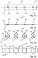
- Fig. 1a shows a top-side view of an embodiment of a LED strip 100 according to the invention in the unfolded state with a plurality of LEDs 120, where the central longitudinal axis L is shown.
- the LED strip 100 for providing indirect light emission according to the invention generally comprises an upper surface 102 and a lower surface 104 opposite to the upper surface 102.
- the LED strip 100 further comprises a plurality of LEDs 120 arranged on the upper surface 102.
- the LED strip 100 has an unfolded state shown in Fig. 1a and 1b and a folded state shown in Fig. 2a and 2b .
- the LED strip 100 is substantially planar in the unfolded state and extends along a central longitudinal axis L.
- the LED strip has a first side 108 and a second side 110 opposite to the first side 108, the first and second side 108 and 110 being parallel to the central longitudinal axis L in the unfolded state.
- the LED strip 100 comprises in the folded state a plurality of first loops 230, as can be seen in Fig. 2a .
- Each loop 230 of the plurality of loops have at least one opening 232 and is provided with at least one of the plurality of LEDs 120, which is configured to emit light towards a reflective interior surface 234 of the loop 230. At least a portion of the light reflected from the reflective interior surface 234 may exit the at least one opening 232 of each loop 230. Thereby, indirect light emission is provided.
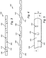
- a part of the lower surface 104 of the LED strip 100 is for attaching the LED strip to a surface (not shown).
- the LED strip 100 is provided for each loop of the plurality of first loops 230 with a first cut 340 extending from the first side 108 and configured to receive the second side 110 in the folded state, such that a loop 230 is created with the upper surface 102 forming the reflective interior surface 234.
- the LED strip 100 is provided for each loop 230 of the plurality of first loops 230 with a second cut 342 extending from the second side 110.
- the first cut 340 is configured to receive the second cut 342 in the folded state such that a loop 230 is created with the upper surface 102 forming the reflective interior surface 232.
- Fig. 5 shows a top-side view of a portion of the LED strip shown in Fig. 3 , showing dimensions of the strip.
- the LED strip 100 has a width W perpendicular to the central longitudinal axis L.
- the first cut 340 extends in the direction perpendicular to the central longitudinal axis L a distance d1 into the LED strip 100
- the second cut 342 extends in the direction perpendicular to the central longitudinal axis L a distance d2 into the LED strip 100.
- the sum of d1 and d2 equals W.
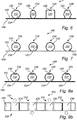
- Fig. 6 shows a side-view of a LED strip 100 according to the invention in the folded state, in an embodiment comprising a plurality of first loops 230 of different shapes.
- the shape of the loops 230 can be circular, oval, squared or hexagonal.
- Fig. 7 shows a side-view of a LED strip 100 according to the invention in the folded state, in an embodiment comprising a plurality of first loops 230 having a plurality of LEDs 120 positioned at different places inside the loops.
- the different positions of the LEDs 120 makes it possible to reflect the light in different angles and create a different illumination.
- Fig. 8a shows a side-view of a LED strip 100 according to the invention in the folded state, in an embodiment comprising a plurality of first loops 230 comprising side emitting LEDs 120.
- Fig. 8b a top-side view of the LED strip 100 shown in Fig. 8a is shown, in an embodiment where the light emitted from the side emitting LEDs 120 exits different openings 232 of the loops 230.
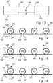
- At least one loop of the plurality of first loops 230 has a plurality of LEDs.
- the LED strip 100 shown in Fig. 9 the plurality of LEDs 120 in each first loop 230 are of different colors or color temperatures.
- the plurality of LEDs may be RGB LEDs, such that by blending different colors any color combination may be provided.
- Fig. 11 shows a side-view of a LED strip 100 according to the invention in the folded state, in an embodiment comprising a plurality of first loops 230, where the loops 230 are arranged with a varying pitch.
- Fig. 12 shows a side-view of a LED strip 100 according to the invention in the folded state, in an embodiment comprising a plurality of first loops 230 where the loops 230 are arranged with a pitch, such that the loops 230 are in contact with each other.
- a part of the upper surface 102 of the LED strip 100 is for attaching the LED strip 100 to a surface (not shown).
- Each loop 230 of the plurality of first loops is provided with two pre-bended portions 350 that are spaced apart by a distance d3 in an unfolded state, shown in Fig. 13 and with a distance d4 in a folded state, shown in Fig. 14 .
- d4 is less than 25 % of d3, preferably less than 10 %, such that a loop 230 is created with the upper surface 102 forming the reflective interior surface 234 as can be seen in Fig, 14 .
- each loop 230 of the plurality of first loops 230 has a starting portion S and an ending portion E.
- the first side 108 of the starting portion S is arranged adjacent to the second side 110 of the ending portion E in the folded state, such that a loop 230 is created with the upper surface 102 forming the reflective interior surface 234.
- each loop 230 of the plurality of first loops 230 has a starting portion S and an ending portion E.
- the first side 108 of the starting portion S is arranged adjacent to the second side 110 of the ending portion E in the folded state, and for the remaining loops the second side 110 of the starting portion S is arranged adjacent to the first side 108 of the ending portion E in the folded state, such that a central axis of the LED strip in the folded state, is parallel with the central longitudinal axis L of the LED strip 100 in the unfolded state.
- a system 300 comprising a first LED strip 100 according to the embodiment shown in Fig. 14 , and a second strip 460 attached to a part of the upper surface 102 of the first LED strip 100, when the first LED strip 100 is in folded state, for stabilizing the first LED strip 100.
- the second strip 460 is a second LED strip 460, comprising a plurality of LEDs 120.
- the first pre-bended portion 350 and the second pre-bended portion 350 abut a LED 120 of the plurality of LEDs of the second LED strip 460.
- each first loop thereby a plurality of LEDs 120 is provided in each first loop, whereby more light may be reflected by the reflective interior surface 234 of the loops 230. Furthermore, light may be reflected in different directions and with different angles.
- the LED strip 100 comprises a plurality of adhesive portions 280, on the lower surface 104.
- Fig. 24a shows the upper surface 102 of a LED strip 100 according to an embodiment of the invention in the unfolded state with a plurality of LEDs 120.
- Fig. 24b shows the lower surface 104 of a LED strip 100 according to an embodiment of the invention in the unfolded state with a plurality of adhesive portions 280.
- Fig. 24c shows a side-view of the LED strip 100 shown in Figs. 24a and 24b , where both the LEDs 120 and the adhesive portions 280 can be seen.
- the adhesive portions 280 are equally distributed over at least a part of the LED strip 100, with a distance d5 between two neighboring adhesive portions 280 in the unfolded state.
- the distance d5 is defined as the shortest distance between two neighboring adhesive portions 280, as shown in Fig. 24b .
- the distance d5 is larger or equal to the circumference of one loop 230 in the folded state.
- the distance d5 is smaller or equal to the distance between the middle of two neighbouring LEDs 120 in the unfolded state.
- the plurality of adhesive portions 280 are protected by a removable film (not shown), arranged to be removed to unveal the adhesive portions 280.
- a luminaire or light fitting 800 is provided with a LED strip 100 according to the invention, that is arranged in the folded state, such that the luminaire 800 provides indirect light emission.
Landscapes
- Engineering & Computer Science (AREA)
- General Engineering & Computer Science (AREA)
- Physics & Mathematics (AREA)
- Microelectronics & Electronic Packaging (AREA)
- Optics & Photonics (AREA)
- Non-Portable Lighting Devices Or Systems Thereof (AREA)
- Fastening Of Light Sources Or Lamp Holders (AREA)
- Structures For Mounting Electric Components On Printed Circuit Boards (AREA)
- Structure Of Printed Boards (AREA)
- Led Device Packages (AREA)
Claims (15)
- LED-Streifen (100) zum Bereitstellen von indirekter Lichtemission, der eine obere Fläche (102) und eine der oberen Fläche gegenüberliegende untere Fläche (104) aufweist, wobei der LED-Streifen eine Vielzahl von LEDs (120) umfasst, die an der oberen Fläche angeordnet sind, wobei der LED-Streifen einen entfalteten Zustand und einen gefalteten Zustand aufweist, wobei der LED-Streifen im entfalteten Zustand im Wesentlichen plan ist und sich entlang einer Mittellängsachse erstreckt, wobei der LED-Streifen eine erste Seite (108) und eine der ersten Seite gegenüberliegende zweite Seite (110) umfasst, wobei die erste und zweite Seite im entfalteten Zustand zur Mittellängsachse (L) parallel sind, wobei der LED-Streifen im gefalteten Zustand eine Vielzahl von ersten Schleifen (230) aufweist, wobei jede aus der Vielzahl von ersten Schleifen mindestens eine Öffnung (232) umfasst und mit mindestens einer aus der Vielzahl von LEDs versehen ist, die dazu ausgelegt ist, Licht in Richtung einer reflektierenden Innenfläche (234) der Schleife zu emittieren, wobei mindestens ein von der reflektierenden Innenfläche reflektierter Teil des Lichts aus der mindestens einen Öffnung jeder Schleife aus der Vielzahl von ersten Schleifen austreten kann, wodurch indirekte Lichtemission bereitgestellt wird.
- LED-Streifen nach Anspruch 1, wobei ein Teil der unteren Fläche des LED-Streifens dafür dient, den LED-Streifen an einer Fläche anzubringen, wobei der LED-Streifen für jede Schleife aus der Vielzahl von ersten Schleifen mit einem ersten Einschnitt versehen ist, der sich ab der ersten Seite erstreckt und dazu ausgelegt ist, im gefalteten Zustand die zweite Seite derart aufzunehmen, dass eine Schleife erzeugt wird, wobei die obere Fläche die reflektierende Innenfläche bildet.
- LED-Streifen nach Anspruch 2, wobei der LED-Streifen für jede Schleife aus der Vielzahl von ersten Schleifen mit einem zweiten Einschnitt versehen ist, der sich ab der zweiten Seite erstreckt, wobei der erste Einschnitt dazu ausgelegt ist, im gefalteten Zustand den zweiten Einschnitt derart aufzunehmen, dass eine Schleife erzeugt wird, wobei die obere Fläche die reflektierende Innenfläche bildet.
- LED-Streifen nach Anspruch 3, wobei der LED-Streifen senkrecht zur Mittellängsachse eine Breite W aufweist, wobei sich der erste Einschnitt in der Richtung senkrecht zur Mittellängsachse einen Abstand d1 in den LED-Streifen hinein erstreckt, und sich der zweite Einschnitt in der Richtung senkrecht zur Mittellängsachse einen Abstand d2 in den LED-Streifen hinein erstreckt, wobei die Summe aus d1 und d2 im Wesentlichen gleich W ist.
- LED-Streifen nach Anspruch 1, wobei mindestens eine Schleife einen Anfangsabschnitt und einen Endabschnitt aufweist, wobei im gefalteten Zustand die erste Seite des Anfangsabschnitts an die zweite Seite des Endabschnitts angrenzend angeordnet ist, derart, dass eine Schleife erzeugt wird, wobei die obere Fläche die reflektierende Innenfläche bildet.
- LED-Streifen nach Anspruch 5, wobei jede Schleife aus der Vielzahl von ersten Schleifen einen Anfangsabschnitt und einen Endabschnitt aufweist, wobei bei jeder Schleife im gefalteten Zustand die erste Seite des Anfangsabschnitts an die zweite Seite des Endabschnitts angrenzend angeordnet ist, derart, dass eine Schleife erzeugt wird, wobei die obere Fläche die reflektierende Innenfläche bildet.
- LED-Streifen nach Anspruch 5, wobei jede Schleife aus der Vielzahl von ersten Schleifen einen Anfangsabschnitt und einen Endabschnitt aufweist, wobei bei jeder zweiten Schleife im gefalteten Zustand die erste Seite des Anfangsabschnitts an die zweite Seite des Endabschnitts angrenzend angeordnet ist, und bei den restlichen Schleifen die zweite Seite des Anfangsabschnitts im gefalteten Zustand an die erste Seite des Endabschnitts angrenzend angeordnet ist, derart, dass eine Mittelachse des LED-Streifens im gefalteten Zustand zur Mittellängsachse des LED-Streifens im entfalteten Zustand parallel ist.
- LED-Streifen nach einem der vorstehenden Ansprüche, wobei der LED-Streifen an der oberen oder unteren Fläche eine Vielzahl von Klebeabschnitten umfasst.
- LED-Streifen nach Anspruch 8, wobei die Klebeabschnitte über mindestens einen Teil des LED-Streifens gleichmäßig verteilt sind, mit einem Abstand d5 zwischen zwei benachbarten Klebeabschnitten im entfalteten Zustand.
- LED-Streifen nach Anspruch 9, wobei der Abstand d5 größer oder gleich dem Umfang einer Schleife im gefalteten Zustand und/oder kleiner oder gleich dem Abstand zwischen der Mitte zweier benachbarter LEDs im entfalteten Zustand ist.
- LED-Streifen nach einem der vorstehenden Ansprüche, wobei mindestens eine Schleife aus der Vielzahl von ersten Schleifen eine Vielzahl von LEDs aufweist.
- LED-Streifen nach einem der Ansprüche 1 oder 8 bis 11, wobei ein Teil der oberen Fläche des LED-Streifens zum Anbringen des LED-Streifens an einer Fläche dient, jede Schleife aus der Vielzahl von ersten Schleifen mit mindestens zwei vorgebogenen Abschnitten versehen ist, wobei die mindestens zwei vorgebogenen Abschnitt in einem entfalteten Zustand um einen Abstand d3 und in einem gefalteten Zustand mit einem Abstand d4 beabstandet sind, wobei d4 weniger als 25 % von d3, vorzugsweise weniger als 10 % beträgt, derart, dass eine Schleife erzeugt wird, wobei die obere Fläche die reflektierende Innenfläche bildet.
- System, das einen ersten LED-Streifen nach Anspruch 12 und einen zweiten Streifen zum Anbringen an einem Teil der oberen Fläche des ersten LED-Streifens umfasst, um den ersten LED-Streifen zu stabilisieren, wenn sich der erste LED-Streifen im gefalteten Zustand befindet.
- System nach Anspruch 13, wobei es sich beim zweiten Streifen um einen zweiten LED-Streifen handelt, der eine Vielzahl von LEDs umfasst, wobei bei jeder Schleife aus der Vielzahl von ersten Schleifen des ersten LED-Streifens der erste vorgebogene Abschnitt und der zweite vorgebogene Abschnitt an eine LED aus der Vielzahl von LEDs des zweiten LED-Streifens anstoßen.
- Leuchte oder Beleuchtungskörper, die/der einen LED-Streifen oder ein System nach einem der Ansprüche 1 bis 14 umfasst, der/das im gefalteten Zustand angeordnet ist, derart, dass die Leuchte oder der Beleuchtungskörper indirekte Lichtemission bereitstellt.
Applications Claiming Priority (2)
| Application Number | Priority Date | Filing Date | Title |
|---|---|---|---|
| EP17187969 | 2017-08-25 | ||
| PCT/EP2018/072414 WO2019038222A1 (en) | 2017-08-25 | 2018-08-20 | LED STRIP FOR INDIRECT LIGHT EMISSION |
Publications (2)
| Publication Number | Publication Date |
|---|---|
| EP3673201A1 EP3673201A1 (de) | 2020-07-01 |
| EP3673201B1 true EP3673201B1 (de) | 2021-01-27 |
Family
ID=59738196
Family Applications (1)
| Application Number | Title | Priority Date | Filing Date |
|---|---|---|---|
| EP18756432.3A Active EP3673201B1 (de) | 2017-08-25 | 2018-08-20 | Led-streifen zur indirekten lichtemission |
Country Status (5)
| Country | Link |
|---|---|
| US (1) | US11067229B2 (de) |
| EP (1) | EP3673201B1 (de) |
| JP (1) | JP7170713B2 (de) |
| CN (1) | CN111065855B (de) |
| WO (1) | WO2019038222A1 (de) |
Families Citing this family (2)
| Publication number | Priority date | Publication date | Assignee | Title |
|---|---|---|---|---|
| CN116348710A (zh) | 2020-10-15 | 2023-06-27 | 昕诺飞控股有限公司 | 照明设备和制造照明设备的方法 |
| US12429177B2 (en) | 2020-11-10 | 2025-09-30 | Signify Holding B.V. | Led light unit |
Citations (2)
| Publication number | Priority date | Publication date | Assignee | Title |
|---|---|---|---|---|
| US20020136004A1 (en) * | 2001-03-16 | 2002-09-26 | Martin Rudoy | Illuminating packaging material |
| US20090226643A1 (en) * | 2008-03-05 | 2009-09-10 | Shu-Chuan Shih | Illuminating decorative bow |
Family Cites Families (26)
| Publication number | Priority date | Publication date | Assignee | Title |
|---|---|---|---|---|
| US3637455A (en) * | 1969-01-17 | 1972-01-25 | Minnesota Mining & Mfg | Prefabricated bow forms |
| US5693381A (en) | 1996-08-02 | 1997-12-02 | Cheng; Peter S. C. | Bow with pop-out decorations |
| LV11956B (lv) * | 1997-09-24 | 1998-04-20 | D�MODARA, individu�lais uz��mums | Dekoratīva lentveida priekšmeta, sasieta pušķī, izgatavošanas paņēmiens |
| US6846094B2 (en) | 2002-08-26 | 2005-01-25 | Altman Stage Lighting, Co., Inc. | Flexible LED lighting strip |
| WO2009130653A1 (en) | 2008-04-23 | 2009-10-29 | Koninklijke Philips Electronics N.V. | A lighting system |
| CA2671360C (en) * | 2008-07-08 | 2017-01-10 | Virginia Optoelectronics, Inc. | Modular led lighting systems and flexible or rigid strip lighting devices |
| US9175811B2 (en) | 2010-02-12 | 2015-11-03 | Cree, Inc. | Solid state lighting device, and method of assembling the same |
| US20130070170A1 (en) * | 2010-05-14 | 2013-03-21 | Yuuki Namekata | Lighting device, display device and television device |
| EP4235015A3 (de) | 2010-12-22 | 2024-02-28 | Signify Holding B.V. | Beleuchtungsvorrichtung und verfahren zur herstellung einer beleuchtungsvorrichtung |
| US8314566B2 (en) * | 2011-02-22 | 2012-11-20 | Quarkstar Llc | Solid state lamp using light emitting strips |
| CN103518097B (zh) * | 2011-04-07 | 2016-03-30 | 3M创新有限公司 | 装饰灯 |
| TWI468621B (zh) * | 2011-07-05 | 2015-01-11 | Ind Tech Res Inst | 照明裝置及其組裝方法 |
| RU2597822C2 (ru) | 2011-08-10 | 2016-09-20 | Конинклейке Филипс Н.В. | Втягивающаяся осветительная арматура |
| JP6192655B2 (ja) * | 2011-11-23 | 2017-09-06 | スリーエム イノベイティブ プロパティズ カンパニー | 三次元構造体を有するフレキシブル発光半導体装置 |
| US9410665B2 (en) | 2012-07-16 | 2016-08-09 | The Sloan Company, Inc. | Flexible ribbon LED module |
| US9696019B2 (en) * | 2012-09-06 | 2017-07-04 | Cooledge Lighting Inc. | LED lighting structure |
| CN203823645U (zh) | 2012-11-02 | 2014-09-10 | 万德莱特有限公司 | 照明设备、用于组装照明设备的零件成套工具及其封装件 |
| WO2014200846A1 (en) | 2013-06-12 | 2014-12-18 | Cooledge Lighting Inc. | Portable lighting systems incorporating deformable light sheets |
| DE202013009434U1 (de) * | 2013-07-12 | 2013-11-05 | Vosla Gmbh | Lampe |
| CN203880449U (zh) | 2014-04-29 | 2014-10-15 | 鹤山丽得电子实业有限公司 | 一种具有弯曲状电路板的led灯泡 |
| CN106664762B (zh) * | 2014-07-18 | 2018-12-07 | 飞利浦照明控股有限公司 | 基于柔性发光条的变形的照明控制 |
| US10317022B2 (en) * | 2014-09-24 | 2019-06-11 | Angler's-Friend, LLC | Spiral wrap lighting system |
| US20160348889A1 (en) * | 2015-05-26 | 2016-12-01 | Timothy Ryan Polanowski | Athletic wear illumination |
| EP3320258B1 (de) | 2015-07-09 | 2018-11-21 | Philips Lighting Holding B.V. | Beleuchtungsmodul und beleuchtungsvorrichtung mit beleuchtungsmodul |
| CN106499985A (zh) * | 2015-09-08 | 2017-03-15 | 李博 | 贴片式led灯条及其成形方法 |
| GB2543750A (en) * | 2015-10-21 | 2017-05-03 | Frederick Fellerman Bernard | LED strips, method of making an LED light, and drive circuits especially for the LED strips |
-
2018
- 2018-08-20 EP EP18756432.3A patent/EP3673201B1/de active Active
- 2018-08-20 WO PCT/EP2018/072414 patent/WO2019038222A1/en not_active Ceased
- 2018-08-20 US US16/640,190 patent/US11067229B2/en active Active
- 2018-08-20 CN CN201880054932.0A patent/CN111065855B/zh active Active
- 2018-08-20 JP JP2020511518A patent/JP7170713B2/ja active Active
Patent Citations (2)
| Publication number | Priority date | Publication date | Assignee | Title |
|---|---|---|---|---|
| US20020136004A1 (en) * | 2001-03-16 | 2002-09-26 | Martin Rudoy | Illuminating packaging material |
| US20090226643A1 (en) * | 2008-03-05 | 2009-09-10 | Shu-Chuan Shih | Illuminating decorative bow |
Also Published As
| Publication number | Publication date |
|---|---|
| CN111065855A (zh) | 2020-04-24 |
| EP3673201A1 (de) | 2020-07-01 |
| US20200182416A1 (en) | 2020-06-11 |
| JP2020532069A (ja) | 2020-11-05 |
| US11067229B2 (en) | 2021-07-20 |
| WO2019038222A1 (en) | 2019-02-28 |
| CN111065855B (zh) | 2022-07-15 |
| JP7170713B2 (ja) | 2022-11-14 |
Similar Documents
| Publication | Publication Date | Title |
|---|---|---|
| JP5081307B2 (ja) | 光学部位置決め装置 | |
| US20110058353A1 (en) | Led-based lamps | |
| US9267674B2 (en) | Solid state light with enclosed light guide and integrated thermal guide | |
| KR20120027401A (ko) | 조명 장치 및 조명 장치 조립 방법 | |
| EP3673201B1 (de) | Led-streifen zur indirekten lichtemission | |
| JP2022544879A (ja) | 3つのタイプのledを備える発光ダイオードフィラメント | |
| CN110234927A (zh) | 发光设备 | |
| US11028977B2 (en) | Light emitting module | |
| JP2018515896A5 (de) | ||
| JP6861890B2 (ja) | コリメート光放射を備えるledストリップ | |
| JP6525974B2 (ja) | 照明装置及び照明器具 | |
| CN103748404A (zh) | 灯泡形灯 | |
| EP4085218B1 (de) | Led-filament-anordnung | |
| KR20110113702A (ko) | 광원 장치 | |
| US10132983B2 (en) | Lamp with floating light source | |
| KR101751016B1 (ko) | 유리컵을 이용한 와이어형 샹들리에 | |
| US12031701B2 (en) | Light emitting device and a luminaire | |
| RU2537828C1 (ru) | Светодиодная лампа | |
| KR20120121985A (ko) | 형광등형 엘이디램프 | |
| KR20180111128A (ko) | 관형 엘이디 램프 | |
| TWM507486U (zh) | 燈體之電子基板結構改良 | |
| WO2025146302A1 (en) | A led filament arrangement | |
| JP2010118316A (ja) | Led照明体 | |
| TW201641876A (zh) | 燈體之電子基板結構改良 |
Legal Events
| Date | Code | Title | Description |
|---|---|---|---|
| STAA | Information on the status of an ep patent application or granted ep patent |
Free format text: STATUS: UNKNOWN |
|
| STAA | Information on the status of an ep patent application or granted ep patent |
Free format text: STATUS: THE INTERNATIONAL PUBLICATION HAS BEEN MADE |
|
| PUAI | Public reference made under article 153(3) epc to a published international application that has entered the european phase |
Free format text: ORIGINAL CODE: 0009012 |
|
| STAA | Information on the status of an ep patent application or granted ep patent |
Free format text: STATUS: REQUEST FOR EXAMINATION WAS MADE |
|
| 17P | Request for examination filed |
Effective date: 20200325 |
|
| AK | Designated contracting states |
Kind code of ref document: A1 Designated state(s): AL AT BE BG CH CY CZ DE DK EE ES FI FR GB GR HR HU IE IS IT LI LT LU LV MC MK MT NL NO PL PT RO RS SE SI SK SM TR |
|
| AX | Request for extension of the european patent |
Extension state: BA ME |
|
| GRAP | Despatch of communication of intention to grant a patent |
Free format text: ORIGINAL CODE: EPIDOSNIGR1 |
|
| STAA | Information on the status of an ep patent application or granted ep patent |
Free format text: STATUS: GRANT OF PATENT IS INTENDED |
|
| DAV | Request for validation of the european patent (deleted) | ||
| DAX | Request for extension of the european patent (deleted) | ||
| INTG | Intention to grant announced |
Effective date: 20200731 |
|
| GRAS | Grant fee paid |
Free format text: ORIGINAL CODE: EPIDOSNIGR3 |
|
| GRAA | (expected) grant |
Free format text: ORIGINAL CODE: 0009210 |
|
| STAA | Information on the status of an ep patent application or granted ep patent |
Free format text: STATUS: THE PATENT HAS BEEN GRANTED |
|
| AK | Designated contracting states |
Kind code of ref document: B1 Designated state(s): AL AT BE BG CH CY CZ DE DK EE ES FI FR GB GR HR HU IE IS IT LI LT LU LV MC MK MT NL NO PL PT RO RS SE SI SK SM TR |
|
| REG | Reference to a national code |
Ref country code: GB Ref legal event code: FG4D |
|
| REG | Reference to a national code |
Ref country code: CH Ref legal event code: EP |
|
| REG | Reference to a national code |
Ref country code: AT Ref legal event code: REF Ref document number: 1358661 Country of ref document: AT Kind code of ref document: T Effective date: 20210215 |
|
| REG | Reference to a national code |
Ref country code: IE Ref legal event code: FG4D |
|
| REG | Reference to a national code |
Ref country code: DE Ref legal event code: R096 Ref document number: 602018012380 Country of ref document: DE |
|
| REG | Reference to a national code |
Ref country code: SE Ref legal event code: TRGR |
|
| REG | Reference to a national code |
Ref country code: NL Ref legal event code: MP Effective date: 20210127 |
|
| REG | Reference to a national code |
Ref country code: LT Ref legal event code: MG9D |
|
| REG | Reference to a national code |
Ref country code: AT Ref legal event code: MK05 Ref document number: 1358661 Country of ref document: AT Kind code of ref document: T Effective date: 20210127 |
|
| PG25 | Lapsed in a contracting state [announced via postgrant information from national office to epo] |
Ref country code: FI Free format text: LAPSE BECAUSE OF FAILURE TO SUBMIT A TRANSLATION OF THE DESCRIPTION OR TO PAY THE FEE WITHIN THE PRESCRIBED TIME-LIMIT Effective date: 20210127 Ref country code: HR Free format text: LAPSE BECAUSE OF FAILURE TO SUBMIT A TRANSLATION OF THE DESCRIPTION OR TO PAY THE FEE WITHIN THE PRESCRIBED TIME-LIMIT Effective date: 20210127 Ref country code: GR Free format text: LAPSE BECAUSE OF FAILURE TO SUBMIT A TRANSLATION OF THE DESCRIPTION OR TO PAY THE FEE WITHIN THE PRESCRIBED TIME-LIMIT Effective date: 20210428 Ref country code: BG Free format text: LAPSE BECAUSE OF FAILURE TO SUBMIT A TRANSLATION OF THE DESCRIPTION OR TO PAY THE FEE WITHIN THE PRESCRIBED TIME-LIMIT Effective date: 20210427 Ref country code: PT Free format text: LAPSE BECAUSE OF FAILURE TO SUBMIT A TRANSLATION OF THE DESCRIPTION OR TO PAY THE FEE WITHIN THE PRESCRIBED TIME-LIMIT Effective date: 20210527 Ref country code: NO Free format text: LAPSE BECAUSE OF FAILURE TO SUBMIT A TRANSLATION OF THE DESCRIPTION OR TO PAY THE FEE WITHIN THE PRESCRIBED TIME-LIMIT Effective date: 20210427 Ref country code: LT Free format text: LAPSE BECAUSE OF FAILURE TO SUBMIT A TRANSLATION OF THE DESCRIPTION OR TO PAY THE FEE WITHIN THE PRESCRIBED TIME-LIMIT Effective date: 20210127 |
|
| PG25 | Lapsed in a contracting state [announced via postgrant information from national office to epo] |
Ref country code: AT Free format text: LAPSE BECAUSE OF FAILURE TO SUBMIT A TRANSLATION OF THE DESCRIPTION OR TO PAY THE FEE WITHIN THE PRESCRIBED TIME-LIMIT Effective date: 20210127 Ref country code: LV Free format text: LAPSE BECAUSE OF FAILURE TO SUBMIT A TRANSLATION OF THE DESCRIPTION OR TO PAY THE FEE WITHIN THE PRESCRIBED TIME-LIMIT Effective date: 20210127 Ref country code: PL Free format text: LAPSE BECAUSE OF FAILURE TO SUBMIT A TRANSLATION OF THE DESCRIPTION OR TO PAY THE FEE WITHIN THE PRESCRIBED TIME-LIMIT Effective date: 20210127 Ref country code: RS Free format text: LAPSE BECAUSE OF FAILURE TO SUBMIT A TRANSLATION OF THE DESCRIPTION OR TO PAY THE FEE WITHIN THE PRESCRIBED TIME-LIMIT Effective date: 20210127 |
|
| PG25 | Lapsed in a contracting state [announced via postgrant information from national office to epo] |
Ref country code: IS Free format text: LAPSE BECAUSE OF FAILURE TO SUBMIT A TRANSLATION OF THE DESCRIPTION OR TO PAY THE FEE WITHIN THE PRESCRIBED TIME-LIMIT Effective date: 20210527 |
|
| REG | Reference to a national code |
Ref country code: DE Ref legal event code: R097 Ref document number: 602018012380 Country of ref document: DE |
|
| PG25 | Lapsed in a contracting state [announced via postgrant information from national office to epo] |
Ref country code: CZ Free format text: LAPSE BECAUSE OF FAILURE TO SUBMIT A TRANSLATION OF THE DESCRIPTION OR TO PAY THE FEE WITHIN THE PRESCRIBED TIME-LIMIT Effective date: 20210127 Ref country code: EE Free format text: LAPSE BECAUSE OF FAILURE TO SUBMIT A TRANSLATION OF THE DESCRIPTION OR TO PAY THE FEE WITHIN THE PRESCRIBED TIME-LIMIT Effective date: 20210127 Ref country code: SM Free format text: LAPSE BECAUSE OF FAILURE TO SUBMIT A TRANSLATION OF THE DESCRIPTION OR TO PAY THE FEE WITHIN THE PRESCRIBED TIME-LIMIT Effective date: 20210127 |
|
| PG25 | Lapsed in a contracting state [announced via postgrant information from national office to epo] |
Ref country code: SK Free format text: LAPSE BECAUSE OF FAILURE TO SUBMIT A TRANSLATION OF THE DESCRIPTION OR TO PAY THE FEE WITHIN THE PRESCRIBED TIME-LIMIT Effective date: 20210127 Ref country code: RO Free format text: LAPSE BECAUSE OF FAILURE TO SUBMIT A TRANSLATION OF THE DESCRIPTION OR TO PAY THE FEE WITHIN THE PRESCRIBED TIME-LIMIT Effective date: 20210127 Ref country code: DK Free format text: LAPSE BECAUSE OF FAILURE TO SUBMIT A TRANSLATION OF THE DESCRIPTION OR TO PAY THE FEE WITHIN THE PRESCRIBED TIME-LIMIT Effective date: 20210127 |
|
| PLBE | No opposition filed within time limit |
Free format text: ORIGINAL CODE: 0009261 |
|
| STAA | Information on the status of an ep patent application or granted ep patent |
Free format text: STATUS: NO OPPOSITION FILED WITHIN TIME LIMIT |
|
| 26N | No opposition filed |
Effective date: 20211028 |
|
| PG25 | Lapsed in a contracting state [announced via postgrant information from national office to epo] |
Ref country code: AL Free format text: LAPSE BECAUSE OF FAILURE TO SUBMIT A TRANSLATION OF THE DESCRIPTION OR TO PAY THE FEE WITHIN THE PRESCRIBED TIME-LIMIT Effective date: 20210127 Ref country code: ES Free format text: LAPSE BECAUSE OF FAILURE TO SUBMIT A TRANSLATION OF THE DESCRIPTION OR TO PAY THE FEE WITHIN THE PRESCRIBED TIME-LIMIT Effective date: 20210127 |
|
| REG | Reference to a national code |
Ref country code: CH Ref legal event code: PL |
|
| PG25 | Lapsed in a contracting state [announced via postgrant information from national office to epo] |
Ref country code: MC Free format text: LAPSE BECAUSE OF FAILURE TO SUBMIT A TRANSLATION OF THE DESCRIPTION OR TO PAY THE FEE WITHIN THE PRESCRIBED TIME-LIMIT Effective date: 20210127 |
|
| REG | Reference to a national code |
Ref country code: BE Ref legal event code: MM Effective date: 20210831 |
|
| PG25 | Lapsed in a contracting state [announced via postgrant information from national office to epo] |
Ref country code: LI Free format text: LAPSE BECAUSE OF NON-PAYMENT OF DUE FEES Effective date: 20210831 Ref country code: CH Free format text: LAPSE BECAUSE OF NON-PAYMENT OF DUE FEES Effective date: 20210831 |
|
| PG25 | Lapsed in a contracting state [announced via postgrant information from national office to epo] |
Ref country code: IS Free format text: LAPSE BECAUSE OF FAILURE TO SUBMIT A TRANSLATION OF THE DESCRIPTION OR TO PAY THE FEE WITHIN THE PRESCRIBED TIME-LIMIT Effective date: 20210527 Ref country code: LU Free format text: LAPSE BECAUSE OF NON-PAYMENT OF DUE FEES Effective date: 20210820 |
|
| PG25 | Lapsed in a contracting state [announced via postgrant information from national office to epo] |
Ref country code: IE Free format text: LAPSE BECAUSE OF NON-PAYMENT OF DUE FEES Effective date: 20210820 Ref country code: BE Free format text: LAPSE BECAUSE OF NON-PAYMENT OF DUE FEES Effective date: 20210831 |
|
| P01 | Opt-out of the competence of the unified patent court (upc) registered |
Effective date: 20230425 |
|
| PG25 | Lapsed in a contracting state [announced via postgrant information from national office to epo] |
Ref country code: NL Free format text: LAPSE BECAUSE OF NON-PAYMENT OF DUE FEES Effective date: 20210127 Ref country code: CY Free format text: LAPSE BECAUSE OF FAILURE TO SUBMIT A TRANSLATION OF THE DESCRIPTION OR TO PAY THE FEE WITHIN THE PRESCRIBED TIME-LIMIT Effective date: 20210127 |
|
| PG25 | Lapsed in a contracting state [announced via postgrant information from national office to epo] |
Ref country code: HU Free format text: LAPSE BECAUSE OF FAILURE TO SUBMIT A TRANSLATION OF THE DESCRIPTION OR TO PAY THE FEE WITHIN THE PRESCRIBED TIME-LIMIT; INVALID AB INITIO Effective date: 20180820 |
|
| PG25 | Lapsed in a contracting state [announced via postgrant information from national office to epo] |
Ref country code: SI Free format text: LAPSE BECAUSE OF FAILURE TO SUBMIT A TRANSLATION OF THE DESCRIPTION OR TO PAY THE FEE WITHIN THE PRESCRIBED TIME-LIMIT Effective date: 20210127 |
|
| PG25 | Lapsed in a contracting state [announced via postgrant information from national office to epo] |
Ref country code: MK Free format text: LAPSE BECAUSE OF FAILURE TO SUBMIT A TRANSLATION OF THE DESCRIPTION OR TO PAY THE FEE WITHIN THE PRESCRIBED TIME-LIMIT Effective date: 20210127 |
|
| PG25 | Lapsed in a contracting state [announced via postgrant information from national office to epo] |
Ref country code: MT Free format text: LAPSE BECAUSE OF FAILURE TO SUBMIT A TRANSLATION OF THE DESCRIPTION OR TO PAY THE FEE WITHIN THE PRESCRIBED TIME-LIMIT Effective date: 20210127 |
|
| PGFP | Annual fee paid to national office [announced via postgrant information from national office to epo] |
Ref country code: DE Payment date: 20241029 Year of fee payment: 7 |
|
| PGFP | Annual fee paid to national office [announced via postgrant information from national office to epo] |
Ref country code: IT Payment date: 20250825 Year of fee payment: 8 |
|
| PGFP | Annual fee paid to national office [announced via postgrant information from national office to epo] |
Ref country code: GB Payment date: 20250826 Year of fee payment: 8 |
|
| PGFP | Annual fee paid to national office [announced via postgrant information from national office to epo] |
Ref country code: FR Payment date: 20250825 Year of fee payment: 8 |
|
| PGFP | Annual fee paid to national office [announced via postgrant information from national office to epo] |
Ref country code: SE Payment date: 20250825 Year of fee payment: 8 |
|
| PG25 | Lapsed in a contracting state [announced via postgrant information from national office to epo] |
Ref country code: TR Free format text: LAPSE BECAUSE OF FAILURE TO SUBMIT A TRANSLATION OF THE DESCRIPTION OR TO PAY THE FEE WITHIN THE PRESCRIBED TIME-LIMIT Effective date: 20210127 |