EP3672781B1 - Forming shoulder and method for producing a forming shoulder - Google Patents
Forming shoulder and method for producing a forming shoulder Download PDFInfo
- Publication number
- EP3672781B1 EP3672781B1 EP18752097.8A EP18752097A EP3672781B1 EP 3672781 B1 EP3672781 B1 EP 3672781B1 EP 18752097 A EP18752097 A EP 18752097A EP 3672781 B1 EP3672781 B1 EP 3672781B1
- Authority
- EP
- European Patent Office
- Prior art keywords
- shoulder
- forming
- piece
- plastic
- prism
- Prior art date
- Legal status (The legal status is an assumption and is not a legal conclusion. Google has not performed a legal analysis and makes no representation as to the accuracy of the status listed.)
- Active
Links
- 238000004519 manufacturing process Methods 0.000 title claims description 13
- 239000002184 metal Substances 0.000 claims description 26
- 238000000034 method Methods 0.000 claims description 9
- 238000007639 printing Methods 0.000 claims description 8
- 238000005452 bending Methods 0.000 description 5
- 238000003754 machining Methods 0.000 description 3
- 238000003801 milling Methods 0.000 description 3
- 238000007493 shaping process Methods 0.000 description 3
- 238000007789 sealing Methods 0.000 description 2
- 238000000149 argon plasma sintering Methods 0.000 description 1
- 238000005266 casting Methods 0.000 description 1
- 238000005520 cutting process Methods 0.000 description 1
- 238000011161 development Methods 0.000 description 1
- 230000018109 developmental process Effects 0.000 description 1
- 238000003698 laser cutting Methods 0.000 description 1
- 239000000463 material Substances 0.000 description 1
- 238000004806 packaging method and process Methods 0.000 description 1
- 238000003466 welding Methods 0.000 description 1
- 230000037303 wrinkles Effects 0.000 description 1
Images

Classifications
-
- B—PERFORMING OPERATIONS; TRANSPORTING
- B29—WORKING OF PLASTICS; WORKING OF SUBSTANCES IN A PLASTIC STATE IN GENERAL
- B29C—SHAPING OR JOINING OF PLASTICS; SHAPING OF MATERIAL IN A PLASTIC STATE, NOT OTHERWISE PROVIDED FOR; AFTER-TREATMENT OF THE SHAPED PRODUCTS, e.g. REPAIRING
- B29C53/00—Shaping by bending, folding, twisting, straightening or flattening; Apparatus therefor
- B29C53/36—Bending and joining, e.g. for making hollow articles
- B29C53/38—Bending and joining, e.g. for making hollow articles by bending sheets or strips at right angles to the longitudinal axis of the article being formed and joining the edges
- B29C53/48—Bending and joining, e.g. for making hollow articles by bending sheets or strips at right angles to the longitudinal axis of the article being formed and joining the edges for articles of indefinite length, i.e. bending a strip progressively
- B29C53/52—Bending and joining, e.g. for making hollow articles by bending sheets or strips at right angles to the longitudinal axis of the article being formed and joining the edges for articles of indefinite length, i.e. bending a strip progressively using external forming surfaces, e.g. sleeves
-
- B—PERFORMING OPERATIONS; TRANSPORTING
- B33—ADDITIVE MANUFACTURING TECHNOLOGY
- B33Y—ADDITIVE MANUFACTURING, i.e. MANUFACTURING OF THREE-DIMENSIONAL [3-D] OBJECTS BY ADDITIVE DEPOSITION, ADDITIVE AGGLOMERATION OR ADDITIVE LAYERING, e.g. BY 3-D PRINTING, STEREOLITHOGRAPHY OR SELECTIVE LASER SINTERING
- B33Y10/00—Processes of additive manufacturing
-
- B—PERFORMING OPERATIONS; TRANSPORTING
- B65—CONVEYING; PACKING; STORING; HANDLING THIN OR FILAMENTARY MATERIAL
- B65B—MACHINES, APPARATUS OR DEVICES FOR, OR METHODS OF, PACKAGING ARTICLES OR MATERIALS; UNPACKING
- B65B9/00—Enclosing successive articles, or quantities of material, e.g. liquids or semiliquids, in flat, folded, or tubular webs of flexible sheet material; Subdividing filled flexible tubes to form packages
- B65B9/10—Enclosing successive articles, or quantities of material, in preformed tubular webs, or in webs formed into tubes around filling nozzles, e.g. extruded tubular webs
- B65B9/20—Enclosing successive articles, or quantities of material, in preformed tubular webs, or in webs formed into tubes around filling nozzles, e.g. extruded tubular webs the webs being formed into tubes in situ around the filling nozzles
- B65B9/22—Forming shoulders; Tube formers
-
- B—PERFORMING OPERATIONS; TRANSPORTING
- B29—WORKING OF PLASTICS; WORKING OF SUBSTANCES IN A PLASTIC STATE IN GENERAL
- B29L—INDEXING SCHEME ASSOCIATED WITH SUBCLASS B29C, RELATING TO PARTICULAR ARTICLES
- B29L2023/00—Tubular articles
- B29L2023/001—Tubular films, sleeves
-
- B—PERFORMING OPERATIONS; TRANSPORTING
- B29—WORKING OF PLASTICS; WORKING OF SUBSTANCES IN A PLASTIC STATE IN GENERAL
- B29L—INDEXING SCHEME ASSOCIATED WITH SUBCLASS B29C, RELATING TO PARTICULAR ARTICLES
- B29L2031/00—Other particular articles
- B29L2031/712—Containers; Packaging elements or accessories, Packages
- B29L2031/7128—Bags, sacks, sachets
-
- B—PERFORMING OPERATIONS; TRANSPORTING
- B33—ADDITIVE MANUFACTURING TECHNOLOGY
- B33Y—ADDITIVE MANUFACTURING, i.e. MANUFACTURING OF THREE-DIMENSIONAL [3-D] OBJECTS BY ADDITIVE DEPOSITION, ADDITIVE AGGLOMERATION OR ADDITIVE LAYERING, e.g. BY 3-D PRINTING, STEREOLITHOGRAPHY OR SELECTIVE LASER SINTERING
- B33Y80/00—Products made by additive manufacturing
Landscapes
- Engineering & Computer Science (AREA)
- Mechanical Engineering (AREA)
- Chemical & Material Sciences (AREA)
- Manufacturing & Machinery (AREA)
- Materials Engineering (AREA)
- Shaping Of Tube Ends By Bending Or Straightening (AREA)
- Moulds For Moulding Plastics Or The Like (AREA)
- Bending Of Plates, Rods, And Pipes (AREA)
Description
Die Erfindung betrifft eine Formschulter nach dem Oberbegriff des Anspruchs 1. Weiter betrifft die Erfindung ein Verfahren zur Herstellung einer Formschulter.The invention relates to a shaped shoulder according to the preamble of claim 1. The invention also relates to a method for producing a shaped shoulder.
Zur Herstellung von Formschultern, wie sie beispielsweise in Schlauchbeutelmaschinen verwendet werden, sind verschiedene Verfahren bekannt. Derartige Formschultern umfassen üblicherweise ein Schulterteil und ein Prismateil, die entlang einer Umformkante miteinander verbunden sind. Eine Möglichkeit zur Herstellung solcher Formschultern besteht darin, jede Formschulter einzeln in Handarbeit herzustellen, indem zunächst die benötigten Einzelteile angefertigt und anschließend montiert werden. Nach der Montage der Einzelteile werden die Maßhaltigkeit der Formschulter und ihr Verhalten im Einsatz geprüft und im Allgemeinen in mehreren Schritten eine Feinbearbeitung durchgeführt, um Abweichungen von den Sollmaßen zu beseitigen, um eine knitterfreie Umformung der ebenen Folienbahn zum gewünschten Folienschlauch zu erreichen.Various methods are known for producing molded shoulders, such as those used in tubular bag machines, for example. Such shaped shoulders usually comprise a shoulder part and a prismatic part, which are connected to one another along a deformation edge. One possibility for producing such molded shoulders is to produce each molded shoulder individually by hand by first making the required individual parts and then assembling them. After the assembly of the individual parts, the dimensional accuracy of the forming shoulder and its behavior in use are checked and, in general, fine processing is carried out in several steps in order to eliminate deviations from the nominal dimensions in order to achieve a crease-free reshaping of the flat film web into the desired film tube.
Häufig kommt ein Herstellungsverfahren zur Anwendung, bei dem die theoretisch ermittelten Einzelteile maschinell, beispielsweise durch Fräsen oder Biegen hergestellt und anschließend manuell zusammengefügt werden. Beispielsweise werden bei einer aus Blech zugeschnittenen Formschulter zunächst die ebenen Abwicklungen der Einzelteile von Schulterteil und Prismateil sowie gegebenenfalls eines Flansches und Stützelements durch Laserschneiden und/oder Fräsen präzise zugeschnitten. Prismateil und Schulterteil werden anschließend weitgehend manuell gerundet und manuell zueinander positioniert und durch Schweißen bzw. Lösen fixiert. Die Rundungsgenauigkeit des Prismateils ist durch Rundungsmaschinen genau herstellbar und messbar.A manufacturing process is often used in which the theoretically determined individual parts are produced by machine, for example by milling or bending, and then assembled manually will. For example, in the case of a shaped shoulder cut from sheet metal, the flat developments of the individual parts of the shoulder part and prism part and possibly a flange and support element are first precisely cut by laser cutting and / or milling. The prism part and shoulder part are then largely manually rounded and manually positioned relative to one another and fixed by welding or loosening. The rounding accuracy of the prism part can be precisely produced and measured by rounding machines.
Prismateile für runde Schlauchquerschnitte werden in der Praxis auch aus Rohrmaterialien gefertigt, wobei die Umformkante auf einer CNC-Fräsmaschine sehr präzise herausgefräst werden kann. Dieses Verfahren ist jedoch aufwendig. Zunächst müssen die Rohre für die verschiedenen Zylinderdurchmesser vorrätig gehalten werden, wobei pro Format immer nur ein sehr kurzes Stück benötigt wird. Die spanende Bearbeitung bei der Herstellung der Umformkante sowie gegebenenfalls beim Ausbringen des Rohres ist teure und aufwendige Feinwerkbearbeitung.In practice, prismatic parts for round hose cross-sections are also made from pipe materials, whereby the formed edge can be milled out very precisely on a CNC milling machine. However, this process is complex. First of all, the tubes for the various cylinder diameters must be kept in stock, whereby only a very short piece is required for each format. The machining in the production of the forming edge and, if necessary, in the removal of the pipe is expensive and time-consuming precision machining.
Um die Biegeform des Schulterteils aus einem Blechzuschnitt herzustellen, sind verschiedene Methoden bekannt. Zum einen kann die endgültige Form durch schrittweises manuelles Biegen des Blechzuschnitts bei stetiger Kontrolle des Biegeergebnisses mit Hilfe von extra angefertigten Biegeleren hergestellt werden. Es ist relativ einfach und schnell, die Form des Schulterblechs vorzubiegen, also zunächst relativ ungenau herzustellen. Die Teile weisen dabei beispielsweise eine Abweichung von +/- 10 mm von der vorgegebenen Form auf. Erforderlich ist jedoch eine Genauigkeit von mindestens +/- 0,2 mm. Deshalb erfordert diese Methode eine große Erfahrung des Arbeiters und viel Zeit.Various methods are known for producing the bending shape of the shoulder part from a sheet metal blank. On the one hand, the final shape can be produced by step-by-step manual bending of the sheet metal blank with constant control of the bending result with the help of specially made bending machines. It is relatively easy and quick to pre-bend the shape of the shoulder plate, i.e. to manufacture it relatively imprecisely at first. The parts have, for example, a deviation of +/- 10 mm from the specified shape. However, an accuracy of at least +/- 0.2 mm is required. Therefore, this method requires a great deal of experience on the part of the worker and a lot of time.
Zum anderen kann die Formung des Schulterteils gleichzeitig mit der Montage des Schulterteils an das vorbereitete Prismateil erfolgen. Dies geht schneller, ist jedoch ungenauer. Stimmt die räumliche Form des Schulterteils nicht mit der theoretisch bestimmten Form überein, wird auch die an sich exakte Kontur der Umformkante am Prismateil entwertet. Es können beispielsweise Falten bei der Schlauchformung entstehen.On the other hand, the shaping of the shoulder part can take place at the same time as the assembly of the shoulder part on the prepared prism part. This is faster, but less accurate. If the spatial shape of the shoulder part does not match the theoretically determined shape, will the exact contour of the forming edge on the prism part is also devalued. For example, wrinkles can occur when the tube is formed.
Aus der
Die
Ausgehend von diesem Stand der Technik ist es deshalb Aufgabe der vorliegenden Erfindung, eine neue Formschulter und ein neues Verfahren zur Herstellung einer Formschulter vorzuschlagen, mit dem die Produktionsergebnisse leichter reproduziert und mit höherer Fertigungsgenauigkeit hergestellt werden können.Based on this prior art, it is therefore the object of the present invention to propose a new forming shoulder and a new method for producing a forming shoulder with which the production results can be reproduced more easily and can be produced with greater manufacturing accuracy.
Diese Aufgabe wird durch eine Formschulter und ein Verfahren nach der Lehre der unabhängigen Hauptansprüche gelöst.This object is achieved by a form shoulder and a method according to the teaching of the independent main claims.
Vorteilhafte Ausführungsformen der Erfindung sind Gegenstand der Unteransprüche.Advantageous embodiments of the invention are the subject of the subclaims.
Die Formschulter beruht auf dem Grundkonzept, dass nur die Umformkante selbst von einem Metallteil gebildet wird. Denn nur die Umformkante der Formschulter ist einem hohen Verschleiß ausgesetzt und muss eine entsprechende Verschleißfestigkeit aufweisen. An das die Umformkante bildende Metallteil sind dann ein aus Kunststoff hergestelltes Schulterteil und/oder ein aus Kunststoff hergestelltes Prismateil angeformt und bilden gemeinsam mit dem Metallteil die Formschulter. Da Kunststoff sich deutlich einfacher und mit einfacheren Mitteln auch durchaus sehr präzise verarbeiten lässt, kann der Herstellungsaufwand und die Reproduzierbarkeit durch Verwendung der Formschulter signifikant verbessert werden.The forming shoulder is based on the basic concept that only the forming edge itself is formed by a metal part. Because only the forming edge of the forming shoulder is exposed to a high level of wear and must have a corresponding wear resistance. A shoulder part made of plastic and / or a prismatic part made of plastic are then molded onto the metal part forming the forming edge and together with the metal part form the shaped shoulder. Since plastic can be processed much more easily and also very precisely with simpler means, the manufacturing effort can be increased and the reproducibility can be significantly improved by using the forming shoulder.
Besonders einfach und kostengünstig ist es, wenn das aus Kunststoff bestehende Schulterteil und/oder das aus Kunststoff bestehende Prismateil erfindungsgemäß mit einem Kunststoffdruckverfahren hergestellt sind.It is particularly simple and inexpensive if the shoulder part made of plastic and / or the prismatic part made of plastic are produced according to the invention using a plastic printing process.
Besonders groß ist der erfindungsgemäße Vorteil, wenn sowohl das Schulterteil als auch das Prismateil aus Kunststoff hergestellt sind, so dass im Wesentlichen nur die Umformkante von einem Metallteil gebildet ist.The advantage according to the invention is particularly great if both the shoulder part and the prism part are made of plastic, so that essentially only the deformed edge is formed by a metal part.
Im Hinblick auf die exakte Formgebung bei der Herstellung der Formschulter und zur Herstellung eines hochfesten Verbunds zwischen dem Metallteil und den Kunststoffteilen der Formschulter ist es besonders vorteilhaft, wenn der Kunststoff des Schulterteils und der Kunststoff des Prismateils miteinander verbunden sind und das Metallteil zur Bildung der Umformkante auf der von der Folie wegweisenden Rückseite umschließt. Im Ergebnis ist dann das die Umformkante bildende Metallteil zumindest teilweise in den Kunststoff des Schulterteils bzw. des Prismateils eingebettet.With regard to the exact shaping during the production of the forming shoulder and for the production of a high-strength bond between the metal part and the plastic parts of the forming shoulder, it is particularly advantageous if the plastic of the shoulder part and the plastic of the prismatic part are connected to one another and the metal part to form the formed edge on the back facing away from the film. As a result, the metal part forming the forming edge is at least partially embedded in the plastic of the shoulder part or the prism part.
Das erfindungsgemäße Verfahren wird dadurch charakterisiert, dass zumindest ein Metallteil zur Bildung einer Umformkante in einer Kunststoffdruckvorrichtung fixiert wird. Anschließend werden das Schulterteil und/oder das Prismateil durch 3D-Kunststoffdruck unter Bildung einer Verbindung zum Metallteil aus Kunststoff hergestellt.The method according to the invention is characterized in that at least one metal part is fixed in a plastic printing device to form a forming edge. The shoulder part and / or the prism part are then produced by 3D plastic printing, forming a connection to the metal part made of plastic.
Eine Ausführungsform der Erfindung ist in den Zeichnungen schematisiert dargestellt und wird nachfolgend beispielhaft erläutert.An embodiment of the invention is shown schematically in the drawings and is explained below by way of example.
Es zeigen:
- Fig. 1
- eine Formschulter in Ansicht von oben;
- Fig. 2
- die Formschulter gemäß
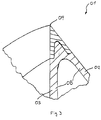
Fig. 1 entlang der Schnittlinie I-I; - Fig. 3
- die Umformkante der Formschulter gemäß
Fig. 2 in einem vergrößerten Detailausschnitt.
- Fig. 1
- a form shoulder in view from above;
- Fig. 2
- the form shoulder according to
Fig. 1 along the section line II; - Fig. 3
- the forming edge of the forming shoulder according to
Fig. 2 in an enlarged detail.
Die übrige Formschulter 01 abgesehen von dem Metallteil 07 besteht aus einem formstabilen Kunststoffteil 08, das das Metallteil 07 auf der Rückseite hintergreift und insgesamt das Schulterteil 02 und das Prismateil 03 bildet. Zur Herstellung der Formschulter 01 wird zunächst das Metallteil 07 in eine 3D-Kunststoffdruckvorrichtung eingespannt und dort die Formschulter 02 und das Prismateil 03 durch 3D-Kunststoffdruck mit hoher Präzision und Wiederholgenauigkeit hergestellt. The rest of the molded
Claims (4)
- A forming shoulder (01) for forming a film tube from a flat film web, the forming shoulder comprising a shoulder piece (02) and a prism piece (03) which are connected to each other along a forming edge (04), the shoulder piece (02) having an outer shoulder surface (05) via which the film web can be guided to an entry opening (06) of the prism piece (03) limited by the forming edge (04), the forming edge (04) being made of at least one metal piece (07), a plastic shoulder piece (02) and/or a plastic prism piece (03) being molded onto the metal piece (07)
characterized in thatthe shoulder piece (02) and/or the prism piece (03) is/are produced using a 3D plastic printing method . - The forming shoulder according to claim 1,
characterized in that
the plastic shoulder piece (02) and the plastic prism piece (03) are molded onto the metal piece (07) forming the forming edge (04), the plastic of the shoulder piece (02) and the plastic of the prism piece (03) being positively bonded to each other and forming a plastic piece (08). - The forming shoulder according to claim 2,
characterized in that
the plastic piece (08) encloses the metal piece (07) on the backside facing away from the film. - A method for producing a forming shoulder (01) for forming a film tube from a flat film web, the forming shoulder comprising a shoulder piece (02) and a prism piece (03) which are connected to each other along a forming edge (04), the shoulder piece (02) having an outer shoulder surface (05) via which the film web can be guided to an entry opening (06) of the prism piece (03) limited by the forming edge (04),
characterized in thata) at least one metal piece (07) is fixated in a 3D plastic printing device for forming the forming edge (04);b) the shoulder piece (02) and/or the prism piece (03) is/are made of plastic using 3D plastic printing and is/are connected to the metal piece (07) in the process.
Applications Claiming Priority (2)
| Application Number | Priority Date | Filing Date | Title |
|---|---|---|---|
| DE102017214651.6A DE102017214651A1 (en) | 2017-08-22 | 2017-08-22 | Form shoulder and method of making a form shoulder |
| PCT/EP2018/069674 WO2019037969A1 (en) | 2017-08-22 | 2018-07-19 | Forming shoulder and method for producing a forming shoulder |
Publications (2)
| Publication Number | Publication Date |
|---|---|
| EP3672781A1 EP3672781A1 (en) | 2020-07-01 |
| EP3672781B1 true EP3672781B1 (en) | 2021-09-01 |
Family
ID=63143107
Family Applications (1)
| Application Number | Title | Priority Date | Filing Date |
|---|---|---|---|
| EP18752097.8A Active EP3672781B1 (en) | 2017-08-22 | 2018-07-19 | Forming shoulder and method for producing a forming shoulder |
Country Status (5)
| Country | Link |
|---|---|
| US (1) | US11794932B2 (en) |
| EP (1) | EP3672781B1 (en) |
| DE (1) | DE102017214651A1 (en) |
| ES (1) | ES2899851T3 (en) |
| WO (1) | WO2019037969A1 (en) |
Family Cites Families (7)
| Publication number | Priority date | Publication date | Assignee | Title |
|---|---|---|---|---|
| DE4038888A1 (en) * | 1990-12-06 | 1992-06-11 | Rovema Gmbh | Plastics bag shaping shoulder production method - mills from cast blank to produce free-forming surfaces |
| DE4320713A1 (en) * | 1993-06-23 | 1995-01-05 | Rampf Giessharzsysteme Gmbh | Forming shoulder for producing and filling tube bags |
| US6589147B2 (en) * | 2001-09-08 | 2003-07-08 | J & F Business, Inc. | Lightweight former and former assembly |
| DE10309020A1 (en) * | 2003-02-21 | 2004-09-02 | GVL Gesellschaft für Verpackungstechnik und -logistik mbH | Forming shoulder for forming tubular packaging from sheet material comprises prismatic plate connected to forming edge, surface of shoulder being made up of movable bars with curved surface |
| DE20320160U1 (en) * | 2003-12-29 | 2004-07-15 | Toss Gmbh & Co. Kg | Forming collar for forming of film sheet into sleeve, especially in bag forming, filling and sealing machine, has at least one part of deflection edge formed by exchangeable insert which is small in comparison to complete forming collar |
| DE102010036229A1 (en) | 2010-09-02 | 2012-03-08 | Henry Drut | Form shoulder and method for its manufacture |
| DE102013207151A1 (en) * | 2013-04-19 | 2014-11-06 | Robert Bosch Gmbh | Form shoulder of a tubular bag packaging machine |
-
2017
- 2017-08-22 DE DE102017214651.6A patent/DE102017214651A1/en not_active Ceased
-
2018
- 2018-07-19 WO PCT/EP2018/069674 patent/WO2019037969A1/en unknown
- 2018-07-19 EP EP18752097.8A patent/EP3672781B1/en active Active
- 2018-07-19 ES ES18752097T patent/ES2899851T3/en active Active
- 2018-07-19 US US16/640,648 patent/US11794932B2/en active Active
Also Published As
| Publication number | Publication date |
|---|---|
| US11794932B2 (en) | 2023-10-24 |
| ES2899851T3 (en) | 2022-03-15 |
| US20200354093A1 (en) | 2020-11-12 |
| DE102017214651A1 (en) | 2019-02-28 |
| WO2019037969A1 (en) | 2019-02-28 |
| EP3672781A1 (en) | 2020-07-01 |
Similar Documents
| Publication | Publication Date | Title |
|---|---|---|
| EP3197633B1 (en) | Method and device for the combined production of components by means of incremental sheet forming and additive methods in one clamping setup | |
| DE102013103612B4 (en) | Process and compression tool for producing highly dimensionally stable half-shells | |
| DE102008037612B4 (en) | Method and tool set for the production of flanged, high-dimensional and deep-drawn half-shells | |
| DE102011115219A1 (en) | Method for preparing metal sheet component for motor vehicle chassis, involves arranging board of metal sheet component material to form sheet material, and completely forming metal sheet component having edge with enlarged edge radius | |
| DE102010023855B4 (en) | Method for producing a metallic valve housing | |
| WO2012146601A1 (en) | Method and device for producing flangeless drawn parts | |
| WO2018115282A1 (en) | Method and device for producing sheet-metal components | |
| EP2208551A2 (en) | Method for producing a complex sheet metal part | |
| WO2016087014A1 (en) | Method and tool system for producing a sheet metal part having at least one sharp sheet metal part edge | |
| EP3672781B1 (en) | Forming shoulder and method for producing a forming shoulder | |
| EP3210766B1 (en) | Fibre laying head for the laying of semi-finished fibre profiles, fibre laying system and method for same | |
| DE10141503C1 (en) | Production of an elongated hollow body comprises roller profiling and deforming a basic body using an internal high pressure deformation process allowing controlled material flow to produce a fixed flange | |
| DE102014005913A1 (en) | Folding device for folding a sheet metal component | |
| DE60007618T2 (en) | METHOD FOR PRODUCING A THIN-WALLED METAL TUBE PIECE | |
| DE102010036229A1 (en) | Form shoulder and method for its manufacture | |
| DE102011118195B4 (en) | Method for producing a refueling system for refueling systems and modular system with prefabricated components for producing a prototype of a deflector device | |
| DE102009016047A1 (en) | Method for manufacturing tubular chassis component i.e. tubular axle carrier, utilized for passenger car, involves forming connection opening in flat outlet plate, inserting thread or thread section into opening and deforming plate | |
| DE102013100944B4 (en) | Form shoulder and process for their manufacture | |
| DE102008056273B4 (en) | Method for producing a closed hollow profile, closed hollow profile produced by this method and device for producing such a closed hollow profile | |
| DE102014218799A1 (en) | Method for producing a three-dimensional fiber composite component | |
| DE19848290C2 (en) | Device and method for producing shell-shaped components made of metal and shell-shaped component made of metal | |
| DE102017205236B4 (en) | A method of manufacturing a component variant of a reshaped and reinforced with a reinforcing patch structural component | |
| DE102009007701B4 (en) | Method for producing a closed profile from a flat strip of material by roll forming | |
| DE202009001645U1 (en) | Apparatus for generating on demand a breakthrough in an equipment part of a vehicle | |
| DE102016222605A1 (en) | Method for producing a torsion tube and manufacturing device for this purpose |
Legal Events
| Date | Code | Title | Description |
|---|---|---|---|
| STAA | Information on the status of an ep patent application or granted ep patent |
Free format text: STATUS: UNKNOWN |
|
| STAA | Information on the status of an ep patent application or granted ep patent |
Free format text: STATUS: THE INTERNATIONAL PUBLICATION HAS BEEN MADE |
|
| PUAI | Public reference made under article 153(3) epc to a published international application that has entered the european phase |
Free format text: ORIGINAL CODE: 0009012 |
|
| STAA | Information on the status of an ep patent application or granted ep patent |
Free format text: STATUS: REQUEST FOR EXAMINATION WAS MADE |
|
| 17P | Request for examination filed |
Effective date: 20200312 |
|
| AK | Designated contracting states |
Kind code of ref document: A1 Designated state(s): AL AT BE BG CH CY CZ DE DK EE ES FI FR GB GR HR HU IE IS IT LI LT LU LV MC MK MT NL NO PL PT RO RS SE SI SK SM TR |
|
| AX | Request for extension of the european patent |
Extension state: BA ME |
|
| DAV | Request for validation of the european patent (deleted) | ||
| DAX | Request for extension of the european patent (deleted) | ||
| GRAP | Despatch of communication of intention to grant a patent |
Free format text: ORIGINAL CODE: EPIDOSNIGR1 |
|
| STAA | Information on the status of an ep patent application or granted ep patent |
Free format text: STATUS: GRANT OF PATENT IS INTENDED |
|
| INTG | Intention to grant announced |
Effective date: 20210316 |
|
| GRAS | Grant fee paid |
Free format text: ORIGINAL CODE: EPIDOSNIGR3 |
|
| GRAA | (expected) grant |
Free format text: ORIGINAL CODE: 0009210 |
|
| STAA | Information on the status of an ep patent application or granted ep patent |
Free format text: STATUS: THE PATENT HAS BEEN GRANTED |
|
| AK | Designated contracting states |
Kind code of ref document: B1 Designated state(s): AL AT BE BG CH CY CZ DE DK EE ES FI FR GB GR HR HU IE IS IT LI LT LU LV MC MK MT NL NO PL PT RO RS SE SI SK SM TR |
|
| REG | Reference to a national code |
Ref country code: GB Ref legal event code: FG4D Free format text: NOT ENGLISH |
|
| REG | Reference to a national code |
Ref country code: CH Ref legal event code: EP Ref country code: AT Ref legal event code: REF Ref document number: 1425772 Country of ref document: AT Kind code of ref document: T Effective date: 20210915 |
|
| REG | Reference to a national code |
Ref country code: DE Ref legal event code: R096 Ref document number: 502018006876 Country of ref document: DE |
|
| REG | Reference to a national code |
Ref country code: IE Ref legal event code: FG4D Free format text: LANGUAGE OF EP DOCUMENT: GERMAN |
|
| REG | Reference to a national code |
Ref country code: NL Ref legal event code: FP |
|
| REG | Reference to a national code |
Ref country code: LT Ref legal event code: MG9D |
|
| PG25 | Lapsed in a contracting state [announced via postgrant information from national office to epo] |
Ref country code: NO Free format text: LAPSE BECAUSE OF FAILURE TO SUBMIT A TRANSLATION OF THE DESCRIPTION OR TO PAY THE FEE WITHIN THE PRESCRIBED TIME-LIMIT Effective date: 20211201 Ref country code: LT Free format text: LAPSE BECAUSE OF FAILURE TO SUBMIT A TRANSLATION OF THE DESCRIPTION OR TO PAY THE FEE WITHIN THE PRESCRIBED TIME-LIMIT Effective date: 20210901 Ref country code: BG Free format text: LAPSE BECAUSE OF FAILURE TO SUBMIT A TRANSLATION OF THE DESCRIPTION OR TO PAY THE FEE WITHIN THE PRESCRIBED TIME-LIMIT Effective date: 20211201 Ref country code: SE Free format text: LAPSE BECAUSE OF FAILURE TO SUBMIT A TRANSLATION OF THE DESCRIPTION OR TO PAY THE FEE WITHIN THE PRESCRIBED TIME-LIMIT Effective date: 20210901 Ref country code: RS Free format text: LAPSE BECAUSE OF FAILURE TO SUBMIT A TRANSLATION OF THE DESCRIPTION OR TO PAY THE FEE WITHIN THE PRESCRIBED TIME-LIMIT Effective date: 20210901 Ref country code: HR Free format text: LAPSE BECAUSE OF FAILURE TO SUBMIT A TRANSLATION OF THE DESCRIPTION OR TO PAY THE FEE WITHIN THE PRESCRIBED TIME-LIMIT Effective date: 20210901 Ref country code: FI Free format text: LAPSE BECAUSE OF FAILURE TO SUBMIT A TRANSLATION OF THE DESCRIPTION OR TO PAY THE FEE WITHIN THE PRESCRIBED TIME-LIMIT Effective date: 20210901 |
|
| PG25 | Lapsed in a contracting state [announced via postgrant information from national office to epo] |
Ref country code: PL Free format text: LAPSE BECAUSE OF FAILURE TO SUBMIT A TRANSLATION OF THE DESCRIPTION OR TO PAY THE FEE WITHIN THE PRESCRIBED TIME-LIMIT Effective date: 20210901 Ref country code: LV Free format text: LAPSE BECAUSE OF FAILURE TO SUBMIT A TRANSLATION OF THE DESCRIPTION OR TO PAY THE FEE WITHIN THE PRESCRIBED TIME-LIMIT Effective date: 20210901 Ref country code: GR Free format text: LAPSE BECAUSE OF FAILURE TO SUBMIT A TRANSLATION OF THE DESCRIPTION OR TO PAY THE FEE WITHIN THE PRESCRIBED TIME-LIMIT Effective date: 20211202 |
|
| REG | Reference to a national code |
Ref country code: ES Ref legal event code: FG2A Ref document number: 2899851 Country of ref document: ES Kind code of ref document: T3 Effective date: 20220315 |
|
| PG25 | Lapsed in a contracting state [announced via postgrant information from national office to epo] |
Ref country code: IS Free format text: LAPSE BECAUSE OF FAILURE TO SUBMIT A TRANSLATION OF THE DESCRIPTION OR TO PAY THE FEE WITHIN THE PRESCRIBED TIME-LIMIT Effective date: 20220101 Ref country code: SM Free format text: LAPSE BECAUSE OF FAILURE TO SUBMIT A TRANSLATION OF THE DESCRIPTION OR TO PAY THE FEE WITHIN THE PRESCRIBED TIME-LIMIT Effective date: 20210901 Ref country code: SK Free format text: LAPSE BECAUSE OF FAILURE TO SUBMIT A TRANSLATION OF THE DESCRIPTION OR TO PAY THE FEE WITHIN THE PRESCRIBED TIME-LIMIT Effective date: 20210901 Ref country code: RO Free format text: LAPSE BECAUSE OF FAILURE TO SUBMIT A TRANSLATION OF THE DESCRIPTION OR TO PAY THE FEE WITHIN THE PRESCRIBED TIME-LIMIT Effective date: 20210901 Ref country code: PT Free format text: LAPSE BECAUSE OF FAILURE TO SUBMIT A TRANSLATION OF THE DESCRIPTION OR TO PAY THE FEE WITHIN THE PRESCRIBED TIME-LIMIT Effective date: 20220103 Ref country code: EE Free format text: LAPSE BECAUSE OF FAILURE TO SUBMIT A TRANSLATION OF THE DESCRIPTION OR TO PAY THE FEE WITHIN THE PRESCRIBED TIME-LIMIT Effective date: 20210901 Ref country code: AL Free format text: LAPSE BECAUSE OF FAILURE TO SUBMIT A TRANSLATION OF THE DESCRIPTION OR TO PAY THE FEE WITHIN THE PRESCRIBED TIME-LIMIT Effective date: 20210901 |
|
| REG | Reference to a national code |
Ref country code: DE Ref legal event code: R097 Ref document number: 502018006876 Country of ref document: DE |
|
| PLBE | No opposition filed within time limit |
Free format text: ORIGINAL CODE: 0009261 |
|
| STAA | Information on the status of an ep patent application or granted ep patent |
Free format text: STATUS: NO OPPOSITION FILED WITHIN TIME LIMIT |
|
| PG25 | Lapsed in a contracting state [announced via postgrant information from national office to epo] |
Ref country code: DK Free format text: LAPSE BECAUSE OF FAILURE TO SUBMIT A TRANSLATION OF THE DESCRIPTION OR TO PAY THE FEE WITHIN THE PRESCRIBED TIME-LIMIT Effective date: 20210901 |
|
| 26N | No opposition filed |
Effective date: 20220602 |
|
| PG25 | Lapsed in a contracting state [announced via postgrant information from national office to epo] |
Ref country code: SI Free format text: LAPSE BECAUSE OF FAILURE TO SUBMIT A TRANSLATION OF THE DESCRIPTION OR TO PAY THE FEE WITHIN THE PRESCRIBED TIME-LIMIT Effective date: 20210901 |
|
| PG25 | Lapsed in a contracting state [announced via postgrant information from national office to epo] |
Ref country code: MC Free format text: LAPSE BECAUSE OF FAILURE TO SUBMIT A TRANSLATION OF THE DESCRIPTION OR TO PAY THE FEE WITHIN THE PRESCRIBED TIME-LIMIT Effective date: 20210901 |
|
| REG | Reference to a national code |
Ref country code: CH Ref legal event code: PL |
|
| REG | Reference to a national code |
Ref country code: BE Ref legal event code: MM Effective date: 20220731 |
|
| PG25 | Lapsed in a contracting state [announced via postgrant information from national office to epo] |
Ref country code: LU Free format text: LAPSE BECAUSE OF NON-PAYMENT OF DUE FEES Effective date: 20220719 Ref country code: LI Free format text: LAPSE BECAUSE OF NON-PAYMENT OF DUE FEES Effective date: 20220731 Ref country code: CH Free format text: LAPSE BECAUSE OF NON-PAYMENT OF DUE FEES Effective date: 20220731 |
|
| PG25 | Lapsed in a contracting state [announced via postgrant information from national office to epo] |
Ref country code: BE Free format text: LAPSE BECAUSE OF NON-PAYMENT OF DUE FEES Effective date: 20220731 |
|
| P01 | Opt-out of the competence of the unified patent court (upc) registered |
Effective date: 20230524 |
|
| PG25 | Lapsed in a contracting state [announced via postgrant information from national office to epo] |
Ref country code: IE Free format text: LAPSE BECAUSE OF NON-PAYMENT OF DUE FEES Effective date: 20220719 |
|
| PGFP | Annual fee paid to national office [announced via postgrant information from national office to epo] |
Ref country code: NL Payment date: 20230720 Year of fee payment: 6 |
|
| PGFP | Annual fee paid to national office [announced via postgrant information from national office to epo] |
Ref country code: IT Payment date: 20230731 Year of fee payment: 6 Ref country code: GB Payment date: 20230724 Year of fee payment: 6 Ref country code: ES Payment date: 20230821 Year of fee payment: 6 Ref country code: CZ Payment date: 20230707 Year of fee payment: 6 |
|
| PGFP | Annual fee paid to national office [announced via postgrant information from national office to epo] |
Ref country code: FR Payment date: 20230724 Year of fee payment: 6 Ref country code: DE Payment date: 20230922 Year of fee payment: 6 |
|
| PG25 | Lapsed in a contracting state [announced via postgrant information from national office to epo] |
Ref country code: MK Free format text: LAPSE BECAUSE OF FAILURE TO SUBMIT A TRANSLATION OF THE DESCRIPTION OR TO PAY THE FEE WITHIN THE PRESCRIBED TIME-LIMIT Effective date: 20210901 Ref country code: CY Free format text: LAPSE BECAUSE OF FAILURE TO SUBMIT A TRANSLATION OF THE DESCRIPTION OR TO PAY THE FEE WITHIN THE PRESCRIBED TIME-LIMIT Effective date: 20210901 |