EP3672780B1 - Ensemble formé 3d - Google Patents
Ensemble formé 3d Download PDFInfo
- Publication number
- EP3672780B1 EP3672780B1 EP18785695.0A EP18785695A EP3672780B1 EP 3672780 B1 EP3672780 B1 EP 3672780B1 EP 18785695 A EP18785695 A EP 18785695A EP 3672780 B1 EP3672780 B1 EP 3672780B1
- Authority
- EP
- European Patent Office
- Prior art keywords
- fibrous
- textile structure
- assembly
- fibrous textile
- wall
- Prior art date
- Legal status (The legal status is an assumption and is not a legal conclusion. Google has not performed a legal analysis and makes no representation as to the accuracy of the status listed.)
- Active
Links
Images


Classifications
-
- B—PERFORMING OPERATIONS; TRANSPORTING
- B29—WORKING OF PLASTICS; WORKING OF SUBSTANCES IN A PLASTIC STATE IN GENERAL
- B29C—SHAPING OR JOINING OF PLASTICS; SHAPING OF MATERIAL IN A PLASTIC STATE, NOT OTHERWISE PROVIDED FOR; AFTER-TREATMENT OF THE SHAPED PRODUCTS, e.g. REPAIRING
- B29C51/00—Shaping by thermoforming, i.e. shaping sheets or sheet like preforms after heating, e.g. shaping sheets in matched moulds or by deep-drawing; Apparatus therefor
- B29C51/14—Shaping by thermoforming, i.e. shaping sheets or sheet like preforms after heating, e.g. shaping sheets in matched moulds or by deep-drawing; Apparatus therefor using multilayered preforms or sheets
- B29C51/145—Shaping by thermoforming, i.e. shaping sheets or sheet like preforms after heating, e.g. shaping sheets in matched moulds or by deep-drawing; Apparatus therefor using multilayered preforms or sheets having at least one layer of textile or fibrous material combined with at least one plastics layer
-
- F—MECHANICAL ENGINEERING; LIGHTING; HEATING; WEAPONS; BLASTING
- F16—ENGINEERING ELEMENTS AND UNITS; GENERAL MEASURES FOR PRODUCING AND MAINTAINING EFFECTIVE FUNCTIONING OF MACHINES OR INSTALLATIONS; THERMAL INSULATION IN GENERAL
- F16L—PIPES; JOINTS OR FITTINGS FOR PIPES; SUPPORTS FOR PIPES, CABLES OR PROTECTIVE TUBING; MEANS FOR THERMAL INSULATION IN GENERAL
- F16L59/00—Thermal insulation in general
- F16L59/02—Shape or form of insulating materials, with or without coverings integral with the insulating materials
- F16L59/026—Mattresses, mats, blankets or the like
-
- B—PERFORMING OPERATIONS; TRANSPORTING
- B29—WORKING OF PLASTICS; WORKING OF SUBSTANCES IN A PLASTIC STATE IN GENERAL
- B29C—SHAPING OR JOINING OF PLASTICS; SHAPING OF MATERIAL IN A PLASTIC STATE, NOT OTHERWISE PROVIDED FOR; AFTER-TREATMENT OF THE SHAPED PRODUCTS, e.g. REPAIRING
- B29C51/00—Shaping by thermoforming, i.e. shaping sheets or sheet like preforms after heating, e.g. shaping sheets in matched moulds or by deep-drawing; Apparatus therefor
- B29C51/006—Shaping by thermoforming, i.e. shaping sheets or sheet like preforms after heating, e.g. shaping sheets in matched moulds or by deep-drawing; Apparatus therefor for making articles having hollow walls
-
- B—PERFORMING OPERATIONS; TRANSPORTING
- B32—LAYERED PRODUCTS
- B32B—LAYERED PRODUCTS, i.e. PRODUCTS BUILT-UP OF STRATA OF FLAT OR NON-FLAT, e.g. CELLULAR OR HONEYCOMB, FORM
- B32B1/00—Layered products having a non-planar shape
-
- B—PERFORMING OPERATIONS; TRANSPORTING
- B32—LAYERED PRODUCTS
- B32B—LAYERED PRODUCTS, i.e. PRODUCTS BUILT-UP OF STRATA OF FLAT OR NON-FLAT, e.g. CELLULAR OR HONEYCOMB, FORM
- B32B15/00—Layered products comprising a layer of metal
- B32B15/14—Layered products comprising a layer of metal next to a fibrous or filamentary layer
-
- B—PERFORMING OPERATIONS; TRANSPORTING
- B32—LAYERED PRODUCTS
- B32B—LAYERED PRODUCTS, i.e. PRODUCTS BUILT-UP OF STRATA OF FLAT OR NON-FLAT, e.g. CELLULAR OR HONEYCOMB, FORM
- B32B15/00—Layered products comprising a layer of metal
- B32B15/18—Layered products comprising a layer of metal comprising iron or steel
-
- B—PERFORMING OPERATIONS; TRANSPORTING
- B32—LAYERED PRODUCTS
- B32B—LAYERED PRODUCTS, i.e. PRODUCTS BUILT-UP OF STRATA OF FLAT OR NON-FLAT, e.g. CELLULAR OR HONEYCOMB, FORM
- B32B15/00—Layered products comprising a layer of metal
- B32B15/20—Layered products comprising a layer of metal comprising aluminium or copper
-
- B—PERFORMING OPERATIONS; TRANSPORTING
- B32—LAYERED PRODUCTS
- B32B—LAYERED PRODUCTS, i.e. PRODUCTS BUILT-UP OF STRATA OF FLAT OR NON-FLAT, e.g. CELLULAR OR HONEYCOMB, FORM
- B32B27/00—Layered products comprising a layer of synthetic resin
- B32B27/12—Layered products comprising a layer of synthetic resin next to a fibrous or filamentary layer
-
- B—PERFORMING OPERATIONS; TRANSPORTING
- B32—LAYERED PRODUCTS
- B32B—LAYERED PRODUCTS, i.e. PRODUCTS BUILT-UP OF STRATA OF FLAT OR NON-FLAT, e.g. CELLULAR OR HONEYCOMB, FORM
- B32B27/00—Layered products comprising a layer of synthetic resin
- B32B27/28—Layered products comprising a layer of synthetic resin comprising synthetic resins not wholly covered by any one of the sub-groups B32B27/30 - B32B27/42
- B32B27/281—Layered products comprising a layer of synthetic resin comprising synthetic resins not wholly covered by any one of the sub-groups B32B27/30 - B32B27/42 comprising polyimides
-
- B—PERFORMING OPERATIONS; TRANSPORTING
- B32—LAYERED PRODUCTS
- B32B—LAYERED PRODUCTS, i.e. PRODUCTS BUILT-UP OF STRATA OF FLAT OR NON-FLAT, e.g. CELLULAR OR HONEYCOMB, FORM
- B32B27/00—Layered products comprising a layer of synthetic resin
- B32B27/28—Layered products comprising a layer of synthetic resin comprising synthetic resins not wholly covered by any one of the sub-groups B32B27/30 - B32B27/42
- B32B27/285—Layered products comprising a layer of synthetic resin comprising synthetic resins not wholly covered by any one of the sub-groups B32B27/30 - B32B27/42 comprising polyethers
-
- B—PERFORMING OPERATIONS; TRANSPORTING
- B32—LAYERED PRODUCTS
- B32B—LAYERED PRODUCTS, i.e. PRODUCTS BUILT-UP OF STRATA OF FLAT OR NON-FLAT, e.g. CELLULAR OR HONEYCOMB, FORM
- B32B27/00—Layered products comprising a layer of synthetic resin
- B32B27/28—Layered products comprising a layer of synthetic resin comprising synthetic resins not wholly covered by any one of the sub-groups B32B27/30 - B32B27/42
- B32B27/288—Layered products comprising a layer of synthetic resin comprising synthetic resins not wholly covered by any one of the sub-groups B32B27/30 - B32B27/42 comprising polyketones
-
- B—PERFORMING OPERATIONS; TRANSPORTING
- B32—LAYERED PRODUCTS
- B32B—LAYERED PRODUCTS, i.e. PRODUCTS BUILT-UP OF STRATA OF FLAT OR NON-FLAT, e.g. CELLULAR OR HONEYCOMB, FORM
- B32B27/00—Layered products comprising a layer of synthetic resin
- B32B27/32—Layered products comprising a layer of synthetic resin comprising polyolefins
-
- B—PERFORMING OPERATIONS; TRANSPORTING
- B32—LAYERED PRODUCTS
- B32B—LAYERED PRODUCTS, i.e. PRODUCTS BUILT-UP OF STRATA OF FLAT OR NON-FLAT, e.g. CELLULAR OR HONEYCOMB, FORM
- B32B3/00—Layered products comprising a layer with external or internal discontinuities or unevennesses, or a layer of non-planar shape; Layered products comprising a layer having particular features of form
- B32B3/02—Layered products comprising a layer with external or internal discontinuities or unevennesses, or a layer of non-planar shape; Layered products comprising a layer having particular features of form characterised by features of form at particular places, e.g. in edge regions
- B32B3/04—Layered products comprising a layer with external or internal discontinuities or unevennesses, or a layer of non-planar shape; Layered products comprising a layer having particular features of form characterised by features of form at particular places, e.g. in edge regions characterised by at least one layer folded at the edge, e.g. over another layer ; characterised by at least one layer enveloping or enclosing a material
-
- B—PERFORMING OPERATIONS; TRANSPORTING
- B32—LAYERED PRODUCTS
- B32B—LAYERED PRODUCTS, i.e. PRODUCTS BUILT-UP OF STRATA OF FLAT OR NON-FLAT, e.g. CELLULAR OR HONEYCOMB, FORM
- B32B3/00—Layered products comprising a layer with external or internal discontinuities or unevennesses, or a layer of non-planar shape; Layered products comprising a layer having particular features of form
- B32B3/26—Layered products comprising a layer with external or internal discontinuities or unevennesses, or a layer of non-planar shape; Layered products comprising a layer having particular features of form characterised by a particular shape of the outline of the cross-section of a continuous layer; characterised by a layer with cavities or internal voids ; characterised by an apertured layer
- B32B3/263—Layered products comprising a layer with external or internal discontinuities or unevennesses, or a layer of non-planar shape; Layered products comprising a layer having particular features of form characterised by a particular shape of the outline of the cross-section of a continuous layer; characterised by a layer with cavities or internal voids ; characterised by an apertured layer characterised by a layer having non-uniform thickness
-
- B—PERFORMING OPERATIONS; TRANSPORTING
- B32—LAYERED PRODUCTS
- B32B—LAYERED PRODUCTS, i.e. PRODUCTS BUILT-UP OF STRATA OF FLAT OR NON-FLAT, e.g. CELLULAR OR HONEYCOMB, FORM
- B32B3/00—Layered products comprising a layer with external or internal discontinuities or unevennesses, or a layer of non-planar shape; Layered products comprising a layer having particular features of form
- B32B3/26—Layered products comprising a layer with external or internal discontinuities or unevennesses, or a layer of non-planar shape; Layered products comprising a layer having particular features of form characterised by a particular shape of the outline of the cross-section of a continuous layer; characterised by a layer with cavities or internal voids ; characterised by an apertured layer
- B32B3/30—Layered products comprising a layer with external or internal discontinuities or unevennesses, or a layer of non-planar shape; Layered products comprising a layer having particular features of form characterised by a particular shape of the outline of the cross-section of a continuous layer; characterised by a layer with cavities or internal voids ; characterised by an apertured layer characterised by a layer formed with recesses or projections, e.g. hollows, grooves, protuberances, ribs
-
- B—PERFORMING OPERATIONS; TRANSPORTING
- B32—LAYERED PRODUCTS
- B32B—LAYERED PRODUCTS, i.e. PRODUCTS BUILT-UP OF STRATA OF FLAT OR NON-FLAT, e.g. CELLULAR OR HONEYCOMB, FORM
- B32B5/00—Layered products characterised by the non- homogeneity or physical structure, i.e. comprising a fibrous, filamentary, particulate or foam layer; Layered products characterised by having a layer differing constitutionally or physically in different parts
- B32B5/02—Layered products characterised by the non- homogeneity or physical structure, i.e. comprising a fibrous, filamentary, particulate or foam layer; Layered products characterised by having a layer differing constitutionally or physically in different parts characterised by structural features of a fibrous or filamentary layer
- B32B5/022—Non-woven fabric
-
- B—PERFORMING OPERATIONS; TRANSPORTING
- B32—LAYERED PRODUCTS
- B32B—LAYERED PRODUCTS, i.e. PRODUCTS BUILT-UP OF STRATA OF FLAT OR NON-FLAT, e.g. CELLULAR OR HONEYCOMB, FORM
- B32B5/00—Layered products characterised by the non- homogeneity or physical structure, i.e. comprising a fibrous, filamentary, particulate or foam layer; Layered products characterised by having a layer differing constitutionally or physically in different parts
- B32B5/02—Layered products characterised by the non- homogeneity or physical structure, i.e. comprising a fibrous, filamentary, particulate or foam layer; Layered products characterised by having a layer differing constitutionally or physically in different parts characterised by structural features of a fibrous or filamentary layer
- B32B5/024—Woven fabric
-
- B—PERFORMING OPERATIONS; TRANSPORTING
- B32—LAYERED PRODUCTS
- B32B—LAYERED PRODUCTS, i.e. PRODUCTS BUILT-UP OF STRATA OF FLAT OR NON-FLAT, e.g. CELLULAR OR HONEYCOMB, FORM
- B32B5/00—Layered products characterised by the non- homogeneity or physical structure, i.e. comprising a fibrous, filamentary, particulate or foam layer; Layered products characterised by having a layer differing constitutionally or physically in different parts
- B32B5/14—Layered products characterised by the non- homogeneity or physical structure, i.e. comprising a fibrous, filamentary, particulate or foam layer; Layered products characterised by having a layer differing constitutionally or physically in different parts characterised by a layer differing constitutionally or physically in different parts, e.g. denser near its faces
-
- B—PERFORMING OPERATIONS; TRANSPORTING
- B32—LAYERED PRODUCTS
- B32B—LAYERED PRODUCTS, i.e. PRODUCTS BUILT-UP OF STRATA OF FLAT OR NON-FLAT, e.g. CELLULAR OR HONEYCOMB, FORM
- B32B5/00—Layered products characterised by the non- homogeneity or physical structure, i.e. comprising a fibrous, filamentary, particulate or foam layer; Layered products characterised by having a layer differing constitutionally or physically in different parts
- B32B5/14—Layered products characterised by the non- homogeneity or physical structure, i.e. comprising a fibrous, filamentary, particulate or foam layer; Layered products characterised by having a layer differing constitutionally or physically in different parts characterised by a layer differing constitutionally or physically in different parts, e.g. denser near its faces
- B32B5/145—Variation across the thickness of the layer
-
- B—PERFORMING OPERATIONS; TRANSPORTING
- B32—LAYERED PRODUCTS
- B32B—LAYERED PRODUCTS, i.e. PRODUCTS BUILT-UP OF STRATA OF FLAT OR NON-FLAT, e.g. CELLULAR OR HONEYCOMB, FORM
- B32B5/00—Layered products characterised by the non- homogeneity or physical structure, i.e. comprising a fibrous, filamentary, particulate or foam layer; Layered products characterised by having a layer differing constitutionally or physically in different parts
- B32B5/22—Layered products characterised by the non- homogeneity or physical structure, i.e. comprising a fibrous, filamentary, particulate or foam layer; Layered products characterised by having a layer differing constitutionally or physically in different parts characterised by the presence of two or more layers which are next to each other and are fibrous, filamentary, formed of particles or foamed
- B32B5/24—Layered products characterised by the non- homogeneity or physical structure, i.e. comprising a fibrous, filamentary, particulate or foam layer; Layered products characterised by having a layer differing constitutionally or physically in different parts characterised by the presence of two or more layers which are next to each other and are fibrous, filamentary, formed of particles or foamed one layer being a fibrous or filamentary layer
- B32B5/26—Layered products characterised by the non- homogeneity or physical structure, i.e. comprising a fibrous, filamentary, particulate or foam layer; Layered products characterised by having a layer differing constitutionally or physically in different parts characterised by the presence of two or more layers which are next to each other and are fibrous, filamentary, formed of particles or foamed one layer being a fibrous or filamentary layer another layer next to it also being fibrous or filamentary
-
- B—PERFORMING OPERATIONS; TRANSPORTING
- B60—VEHICLES IN GENERAL
- B60R—VEHICLES, VEHICLE FITTINGS, OR VEHICLE PARTS, NOT OTHERWISE PROVIDED FOR
- B60R13/00—Elements for body-finishing, identifying, or decorating; Arrangements or adaptations for advertising purposes
- B60R13/08—Insulating elements, e.g. for sound insulation
- B60R13/0815—Acoustic or thermal insulation of passenger compartments
-
- B—PERFORMING OPERATIONS; TRANSPORTING
- B29—WORKING OF PLASTICS; WORKING OF SUBSTANCES IN A PLASTIC STATE IN GENERAL
- B29C—SHAPING OR JOINING OF PLASTICS; SHAPING OF MATERIAL IN A PLASTIC STATE, NOT OTHERWISE PROVIDED FOR; AFTER-TREATMENT OF THE SHAPED PRODUCTS, e.g. REPAIRING
- B29C2791/00—Shaping characteristics in general
- B29C2791/004—Shaping under special conditions
- B29C2791/006—Using vacuum
-
- B—PERFORMING OPERATIONS; TRANSPORTING
- B29—WORKING OF PLASTICS; WORKING OF SUBSTANCES IN A PLASTIC STATE IN GENERAL
- B29C—SHAPING OR JOINING OF PLASTICS; SHAPING OF MATERIAL IN A PLASTIC STATE, NOT OTHERWISE PROVIDED FOR; AFTER-TREATMENT OF THE SHAPED PRODUCTS, e.g. REPAIRING
- B29C51/00—Shaping by thermoforming, i.e. shaping sheets or sheet like preforms after heating, e.g. shaping sheets in matched moulds or by deep-drawing; Apparatus therefor
- B29C51/002—Shaping by thermoforming, i.e. shaping sheets or sheet like preforms after heating, e.g. shaping sheets in matched moulds or by deep-drawing; Apparatus therefor characterised by the choice of material
-
- B—PERFORMING OPERATIONS; TRANSPORTING
- B29—WORKING OF PLASTICS; WORKING OF SUBSTANCES IN A PLASTIC STATE IN GENERAL
- B29K—INDEXING SCHEME ASSOCIATED WITH SUBCLASSES B29B, B29C OR B29D, RELATING TO MOULDING MATERIALS OR TO MATERIALS FOR MOULDS, REINFORCEMENTS, FILLERS OR PREFORMED PARTS, e.g. INSERTS
- B29K2105/00—Condition, form or state of moulded material or of the material to be shaped
- B29K2105/06—Condition, form or state of moulded material or of the material to be shaped containing reinforcements, fillers or inserts
- B29K2105/08—Condition, form or state of moulded material or of the material to be shaped containing reinforcements, fillers or inserts of continuous length, e.g. cords, rovings, mats, fabrics, strands or yarns
-
- B—PERFORMING OPERATIONS; TRANSPORTING
- B29—WORKING OF PLASTICS; WORKING OF SUBSTANCES IN A PLASTIC STATE IN GENERAL
- B29K—INDEXING SCHEME ASSOCIATED WITH SUBCLASSES B29B, B29C OR B29D, RELATING TO MOULDING MATERIALS OR TO MATERIALS FOR MOULDS, REINFORCEMENTS, FILLERS OR PREFORMED PARTS, e.g. INSERTS
- B29K2105/00—Condition, form or state of moulded material or of the material to be shaped
- B29K2105/06—Condition, form or state of moulded material or of the material to be shaped containing reinforcements, fillers or inserts
- B29K2105/12—Condition, form or state of moulded material or of the material to be shaped containing reinforcements, fillers or inserts of short lengths, e.g. chopped filaments, staple fibres or bristles
-
- B—PERFORMING OPERATIONS; TRANSPORTING
- B29—WORKING OF PLASTICS; WORKING OF SUBSTANCES IN A PLASTIC STATE IN GENERAL
- B29L—INDEXING SCHEME ASSOCIATED WITH SUBCLASS B29C, RELATING TO PARTICULAR ARTICLES
- B29L2031/00—Other particular articles
- B29L2031/30—Vehicles, e.g. ships or aircraft, or body parts thereof
- B29L2031/3005—Body finishings
-
- B—PERFORMING OPERATIONS; TRANSPORTING
- B29—WORKING OF PLASTICS; WORKING OF SUBSTANCES IN A PLASTIC STATE IN GENERAL
- B29L—INDEXING SCHEME ASSOCIATED WITH SUBCLASS B29C, RELATING TO PARTICULAR ARTICLES
- B29L2031/00—Other particular articles
- B29L2031/30—Vehicles, e.g. ships or aircraft, or body parts thereof
- B29L2031/3005—Body finishings
- B29L2031/3014—Door linings
-
- B—PERFORMING OPERATIONS; TRANSPORTING
- B29—WORKING OF PLASTICS; WORKING OF SUBSTANCES IN A PLASTIC STATE IN GENERAL
- B29L—INDEXING SCHEME ASSOCIATED WITH SUBCLASS B29C, RELATING TO PARTICULAR ARTICLES
- B29L2031/00—Other particular articles
- B29L2031/30—Vehicles, e.g. ships or aircraft, or body parts thereof
- B29L2031/3055—Cars
-
- B—PERFORMING OPERATIONS; TRANSPORTING
- B29—WORKING OF PLASTICS; WORKING OF SUBSTANCES IN A PLASTIC STATE IN GENERAL
- B29L—INDEXING SCHEME ASSOCIATED WITH SUBCLASS B29C, RELATING TO PARTICULAR ARTICLES
- B29L2031/00—Other particular articles
- B29L2031/724—Doors
-
- B—PERFORMING OPERATIONS; TRANSPORTING
- B32—LAYERED PRODUCTS
- B32B—LAYERED PRODUCTS, i.e. PRODUCTS BUILT-UP OF STRATA OF FLAT OR NON-FLAT, e.g. CELLULAR OR HONEYCOMB, FORM
- B32B2250/00—Layers arrangement
- B32B2250/03—3 layers
-
- B—PERFORMING OPERATIONS; TRANSPORTING
- B32—LAYERED PRODUCTS
- B32B—LAYERED PRODUCTS, i.e. PRODUCTS BUILT-UP OF STRATA OF FLAT OR NON-FLAT, e.g. CELLULAR OR HONEYCOMB, FORM
- B32B2250/00—Layers arrangement
- B32B2250/40—Symmetrical or sandwich layers, e.g. ABA, ABCBA, ABCCBA
-
- B—PERFORMING OPERATIONS; TRANSPORTING
- B32—LAYERED PRODUCTS
- B32B—LAYERED PRODUCTS, i.e. PRODUCTS BUILT-UP OF STRATA OF FLAT OR NON-FLAT, e.g. CELLULAR OR HONEYCOMB, FORM
- B32B2255/00—Coating on the layer surface
- B32B2255/10—Coating on the layer surface on synthetic resin layer or on natural or synthetic rubber layer
-
- B—PERFORMING OPERATIONS; TRANSPORTING
- B32—LAYERED PRODUCTS
- B32B—LAYERED PRODUCTS, i.e. PRODUCTS BUILT-UP OF STRATA OF FLAT OR NON-FLAT, e.g. CELLULAR OR HONEYCOMB, FORM
- B32B2255/00—Coating on the layer surface
- B32B2255/20—Inorganic coating
- B32B2255/205—Metallic coating
-
- B—PERFORMING OPERATIONS; TRANSPORTING
- B32—LAYERED PRODUCTS
- B32B—LAYERED PRODUCTS, i.e. PRODUCTS BUILT-UP OF STRATA OF FLAT OR NON-FLAT, e.g. CELLULAR OR HONEYCOMB, FORM
- B32B2260/00—Layered product comprising an impregnated, embedded, or bonded layer wherein the layer comprises an impregnation, embedding, or binder material
- B32B2260/02—Composition of the impregnated, bonded or embedded layer
- B32B2260/021—Fibrous or filamentary layer
-
- B—PERFORMING OPERATIONS; TRANSPORTING
- B32—LAYERED PRODUCTS
- B32B—LAYERED PRODUCTS, i.e. PRODUCTS BUILT-UP OF STRATA OF FLAT OR NON-FLAT, e.g. CELLULAR OR HONEYCOMB, FORM
- B32B2260/00—Layered product comprising an impregnated, embedded, or bonded layer wherein the layer comprises an impregnation, embedding, or binder material
- B32B2260/04—Impregnation, embedding, or binder material
- B32B2260/046—Synthetic resin
-
- B—PERFORMING OPERATIONS; TRANSPORTING
- B32—LAYERED PRODUCTS
- B32B—LAYERED PRODUCTS, i.e. PRODUCTS BUILT-UP OF STRATA OF FLAT OR NON-FLAT, e.g. CELLULAR OR HONEYCOMB, FORM
- B32B2262/00—Composition or structural features of fibres which form a fibrous or filamentary layer or are present as additives
- B32B2262/02—Synthetic macromolecular fibres
-
- B—PERFORMING OPERATIONS; TRANSPORTING
- B32—LAYERED PRODUCTS
- B32B—LAYERED PRODUCTS, i.e. PRODUCTS BUILT-UP OF STRATA OF FLAT OR NON-FLAT, e.g. CELLULAR OR HONEYCOMB, FORM
- B32B2262/00—Composition or structural features of fibres which form a fibrous or filamentary layer or are present as additives
- B32B2262/06—Vegetal fibres
- B32B2262/062—Cellulose fibres, e.g. cotton
-
- B—PERFORMING OPERATIONS; TRANSPORTING
- B32—LAYERED PRODUCTS
- B32B—LAYERED PRODUCTS, i.e. PRODUCTS BUILT-UP OF STRATA OF FLAT OR NON-FLAT, e.g. CELLULAR OR HONEYCOMB, FORM
- B32B2262/00—Composition or structural features of fibres which form a fibrous or filamentary layer or are present as additives
- B32B2262/06—Vegetal fibres
- B32B2262/062—Cellulose fibres, e.g. cotton
- B32B2262/065—Lignocellulosic fibres, e.g. jute, sisal, hemp, flax, bamboo
-
- B—PERFORMING OPERATIONS; TRANSPORTING
- B32—LAYERED PRODUCTS
- B32B—LAYERED PRODUCTS, i.e. PRODUCTS BUILT-UP OF STRATA OF FLAT OR NON-FLAT, e.g. CELLULAR OR HONEYCOMB, FORM
- B32B2262/00—Composition or structural features of fibres which form a fibrous or filamentary layer or are present as additives
- B32B2262/10—Inorganic fibres
- B32B2262/101—Glass fibres
-
- B—PERFORMING OPERATIONS; TRANSPORTING
- B32—LAYERED PRODUCTS
- B32B—LAYERED PRODUCTS, i.e. PRODUCTS BUILT-UP OF STRATA OF FLAT OR NON-FLAT, e.g. CELLULAR OR HONEYCOMB, FORM
- B32B2307/00—Properties of the layers or laminate
- B32B2307/10—Properties of the layers or laminate having particular acoustical properties
- B32B2307/102—Insulating
-
- B—PERFORMING OPERATIONS; TRANSPORTING
- B32—LAYERED PRODUCTS
- B32B—LAYERED PRODUCTS, i.e. PRODUCTS BUILT-UP OF STRATA OF FLAT OR NON-FLAT, e.g. CELLULAR OR HONEYCOMB, FORM
- B32B2307/00—Properties of the layers or laminate
- B32B2307/30—Properties of the layers or laminate having particular thermal properties
- B32B2307/304—Insulating
-
- B—PERFORMING OPERATIONS; TRANSPORTING
- B32—LAYERED PRODUCTS
- B32B—LAYERED PRODUCTS, i.e. PRODUCTS BUILT-UP OF STRATA OF FLAT OR NON-FLAT, e.g. CELLULAR OR HONEYCOMB, FORM
- B32B2307/00—Properties of the layers or laminate
- B32B2307/30—Properties of the layers or laminate having particular thermal properties
- B32B2307/306—Resistant to heat
- B32B2307/3065—Flame resistant or retardant, fire resistant or retardant
-
- B—PERFORMING OPERATIONS; TRANSPORTING
- B32—LAYERED PRODUCTS
- B32B—LAYERED PRODUCTS, i.e. PRODUCTS BUILT-UP OF STRATA OF FLAT OR NON-FLAT, e.g. CELLULAR OR HONEYCOMB, FORM
- B32B2307/00—Properties of the layers or laminate
- B32B2307/30—Properties of the layers or laminate having particular thermal properties
- B32B2307/31—Heat sealable
-
- B—PERFORMING OPERATIONS; TRANSPORTING
- B32—LAYERED PRODUCTS
- B32B—LAYERED PRODUCTS, i.e. PRODUCTS BUILT-UP OF STRATA OF FLAT OR NON-FLAT, e.g. CELLULAR OR HONEYCOMB, FORM
- B32B2307/00—Properties of the layers or laminate
- B32B2307/50—Properties of the layers or laminate having particular mechanical properties
- B32B2307/54—Yield strength; Tensile strength
-
- B—PERFORMING OPERATIONS; TRANSPORTING
- B32—LAYERED PRODUCTS
- B32B—LAYERED PRODUCTS, i.e. PRODUCTS BUILT-UP OF STRATA OF FLAT OR NON-FLAT, e.g. CELLULAR OR HONEYCOMB, FORM
- B32B2307/00—Properties of the layers or laminate
- B32B2307/70—Other properties
- B32B2307/72—Density
-
- B—PERFORMING OPERATIONS; TRANSPORTING
- B32—LAYERED PRODUCTS
- B32B—LAYERED PRODUCTS, i.e. PRODUCTS BUILT-UP OF STRATA OF FLAT OR NON-FLAT, e.g. CELLULAR OR HONEYCOMB, FORM
- B32B2307/00—Properties of the layers or laminate
- B32B2307/70—Other properties
- B32B2307/732—Dimensional properties
-
- B—PERFORMING OPERATIONS; TRANSPORTING
- B32—LAYERED PRODUCTS
- B32B—LAYERED PRODUCTS, i.e. PRODUCTS BUILT-UP OF STRATA OF FLAT OR NON-FLAT, e.g. CELLULAR OR HONEYCOMB, FORM
- B32B2307/00—Properties of the layers or laminate
- B32B2307/70—Other properties
- B32B2307/738—Thermoformability
-
- B—PERFORMING OPERATIONS; TRANSPORTING
- B32—LAYERED PRODUCTS
- B32B—LAYERED PRODUCTS, i.e. PRODUCTS BUILT-UP OF STRATA OF FLAT OR NON-FLAT, e.g. CELLULAR OR HONEYCOMB, FORM
- B32B2605/00—Vehicles
- B32B2605/08—Cars
-
- B—PERFORMING OPERATIONS; TRANSPORTING
- B32—LAYERED PRODUCTS
- B32B—LAYERED PRODUCTS, i.e. PRODUCTS BUILT-UP OF STRATA OF FLAT OR NON-FLAT, e.g. CELLULAR OR HONEYCOMB, FORM
- B32B2605/00—Vehicles
- B32B2605/10—Trains
-
- B—PERFORMING OPERATIONS; TRANSPORTING
- B32—LAYERED PRODUCTS
- B32B—LAYERED PRODUCTS, i.e. PRODUCTS BUILT-UP OF STRATA OF FLAT OR NON-FLAT, e.g. CELLULAR OR HONEYCOMB, FORM
- B32B2605/00—Vehicles
- B32B2605/12—Ships
-
- B—PERFORMING OPERATIONS; TRANSPORTING
- B32—LAYERED PRODUCTS
- B32B—LAYERED PRODUCTS, i.e. PRODUCTS BUILT-UP OF STRATA OF FLAT OR NON-FLAT, e.g. CELLULAR OR HONEYCOMB, FORM
- B32B2605/00—Vehicles
- B32B2605/18—Aircraft
Definitions
- the present invention relates to an assembly formed in three dimensions.
- lining elements typically interior lining, as in a vehicle, such as an aircraft, a ship, a train or an automobile, are already used for protection purposes, typically thermal and/or acoustic protection, or even as fire barrier element.
- the floor and the walls connecting the passenger compartment to the trunk space and the passenger compartment to the engine space are lined with insulating molded parts.
- These molded parts must be adapted to sometimes complex chassis parts, irregular in mechanical strength and/or protection capacity.
- Some three-dimensional molded parts for example for sound insulation, can be produced from PU (polyurethane) foam.
- PU foam is also difficult to recycle.
- Moldings made from conventional fiber mats, which are made from fiber materials by rollers, are only suitable to a limited degree. Fiber mats can only be used for rooms with low distorted. Also, due to the rolling method, they do not exhibit a uniform density distribution. Therefore, they often do not match the geometric and acoustic requirements imposed on these special castings.
- fibers is to be understood conventionally. These are elongated elements having a length L (which corresponds to its largest dimension) and, transversely to this length, a section along which the fiber has a main dimension d (such as a width or a diameter), with a ratio such that L ⁇ 5d, and preferably L ⁇ 10d.
- d such as a width or a diameter
- the textile nature of the fibrous textile structure provides a structuring effect, resulting in a fairly light assembly and shapes that can be very varied.
- the envelope comprising the polymer film serves as protection (no direct contact with the fibers whose dispersion is avoided, nor with the fibrous textile structure, which is also protected).
- the film can also facilitate handling and storage.
- said wall of the closed envelope comprises (or consists of) a said thermoformed polymer film (polymer alone or metal-lined)
- a thermoformed assembly will be obtained, the shape of which will have been able to be defined with perhaps more precision, or even possibilities, than with a metal wall (steel or aluminum, for example), as to the curved shape and/or the reliefs (21 below) and/or the hollows (23 below) that can be wish to obtain.
- thermoformable polymer film in accordance with its conventional definition, this envelope will therefore be a flexible object whose shape (like its material: the film) and that of the fibrous textile structure that it surrounds marry one another, the other.
- a synonym is then: bag or pouch.
- the fibers contained in the three-dimensional fibrous textile structure may or may not be bonded together by a binder (implied chemical).
- thermoformed polymer film the combination between the wall of the envelope and the fibrous textile structure will make it possible both to achieve and to maintain over time a 3D shape that is both light, with an interesting thermal and/or acoustic characteristic, or even mechanically strong, depending on the fiber densities selected.
- said wall has a breaking strength greater than 1 MPa, and preferably between 10 MPa and 300 MPa.
- said wall may impose on the fibrous textile structure the expected 3D shape, by forcing it to deform by relative to its raw initial shape, typically a 2D shape.
- the fiber density in the envelope be between 5 kg/m3 and 250 kg/m3 and preferably between 50 kg/m3 and 130 kg/m3.
- the density of the fibrous textile structure will then be between 10 kg/m3 and 300 kg/m3 and preferably between 60 kg/m3 and 150 kg/m3.
- said wall of the envelope is a film with a thickness of less than 500 microns, it is recommended that the assembly obtained has a maximum thickness less than or equal to 8 mm and preferably less than 3 mm.
- the assembly obtained has a maximum thickness less than or equal to 8 mm and preferably less than 3 mm.
- the fibrous textile structure can comprise a binder, so that a matrix is formed where said fibers will thus be linked together at their zones of contact or intersection between them. But this is not compulsory. Both assumptions are discussed in more detail below.
- the binder will preferably comprise a glue and/or an adhesive.
- said assembly may further comprise, in the casing, a thermal insulator, so that at ambient temperature and pressure, the thermoformed assembly has, through the polymer film, a coefficient of thermal conductivity ( ⁇ ) less than 40mW/m.K.
- ambient temperature and pressure mean respectively 20°C and 10 5 Pa, to within 10%.
- the thermal insulation such as an airgel
- the thermal insulation can be placed in the envelope, in the fibrous textile structure.
- This makes it easier to obtain the thermoformed assembly and limits its cost, while allowing very varied shapes and effects.
- various protective agents depending on the concentration used.
- the binder can then freeze and hold the thermal insulation in place.
- the polymer film will then be used for another effect, by increasing the thermal protection effect of said assembly, due to the depression created in the envelope.
- the casing may include (at least) a phase change material (PCM).
- PCM phase change material
- phase change material it will be possible for this phase change material to be dispersed in the envelope, within the fibrous structure, with the advantages already mentioned.
- said assembly will present favorably, to within 5%, a thickness between 0.8 and 20mm, and a density between 5 and 350Kg/m3.
- the pore volume (void space) will be between 80 and 99% (by volume).
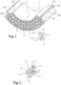
- figure 1 a set 1 thermoformed in three dimensions.
- thermoformed assembly 1 like therefore the fibrous textile structure 5, is shown bent; but they could also have common local reliefs and/or hollows, such as for example in zones 25, 27 respectively on the figure 7 , or in figure 5.6 (areas 21, 23). In English, these depressions and reliefs (or bumps) can be "embossments”.
- the fibrous textile structure 5 is a woven or a nonwoven.
- a felt pen will be a priori interesting.
- felt denotes a non-woven structure obtained by pressing and agglutinating fibers.
- the felt or more generally the fibrous textile structure 5, can take the form of a plate (see figure 8 : e ⁇ I ⁇ L) or a block (e ⁇ I ⁇ L).
- the shape will typically be 2D (planar). There may be several parts side by side or superimposed. A chemical binder is not required (solution of the figure 8 ).
- the wall 7a can be a metal wall a few tenths of a mm thick or else be thermoformable, in the sense that it then comprises a polymer film (or a complex or composite film, such as in particular polymer and metal: metallized PET film where a PET film was vaporized by aluminum) which was thermoformed.
- the polymer film 7a will have been thermoformed at the location of the two major (or main) surfaces, S1 and S2 picture 3 Or 6 (surfaces opposite each other, in dashed lines), between which the fibrous textile structure 5, which is three-dimensional, has a curved shape and/or reliefs 21 and/or hollows 23.
- This thermoforming of the polymer film 7a will therefore not have been limited, as in a 2D flat part, to the minor/marginal peripheral zone in terms of surface (zones 7b figure 1 , 3 since these are cuts) where there is inter-binding of the sheets forming the film 7a and where these sheets are sealed together, typically heat-sealed, to close the envelope.
- the envelope 7 contains the fibrous structure 5 in a closed manner; and its wall 7a follows (or follows) the shape of this fibrous structure, where it faces it (major surfaces S1 and S2).
- the plate will differ from the block in that there is then a ratio of at least five between the thickness e3 and the length (L3) and width (l3).
- the sealing on itself of the wall 7a could have consisted of gluing or welding.
- the fibrous textile structure 5 and the envelope 7 retain, as initially, their respective structural identities. They are not merged. They remain distinctly identifiable; they are structurally independent of each other: It is possible to cut the casing 7 and remove it from its position around the fibrous structure 5 without having to tear it off. It is therefore not a coating or a surface layer (coating in English, as in US4035215 ).
- the material 7a will favorably have a thickness of between 30 and 800 microns, preferably between 30 and 450 microns and even more preferably between 50 and 150 microns.
- fibers other than polymers mineral (glass, basalt for example) or natural (cellulose, flax, hemp for example) can be used.
- the fibers 3 do not will not be bound together by a compound forming a (chemical) binder. Without a binder to join them together (see below and figure 8 , in a raw form of the product, before placing in an envelope and thermoforming), the fibers 3 are nevertheless linked by the textile nature of the structure 5 which they form.
- this structure 5 is a felt, its non-woven nature ensures the fibers their cohesion, the latter being in fact then agglomerated together, for example by blowing, and pressurized, with possible scalding, in the initial raw form, which will a priori be a 2D shape.
- the assembly 1 has a maximum thickness less than or equal to 20mm, preferably 8mm and even more preferably 3mm. And if a thermoformed polymer film 7a is used, it is recommended that it then has a tensile strength such that the desired integrity of the 3D shape is maintained.
- This tensile strength in English / UTS, often abbreviated as (TS), or “ultimate strength", Ftu) of a type 7a film, whether in a version after the aforementioned thermoforming step , or before (state of this film as marketed before its implementation in accordance with the present invention), will be favorably greater than 1 MPa, and preferably between 10 MPa and 300 MPa and even more preferably between 50 MPa and 100 MPa.
- the formed assembly 1 has first zones 10a1 having a first thickness e1 and second zones 10b1 having a second thickness e2 greater than the first thickness e1 (e1 ⁇ e2), the first zones 10a1 having a density of fibers 3 greater than the density of fibers 3 of the second zones 10b1; see figure 7 where, if the maximum thickness is assumed to be e2, we will have e2 ⁇ 8mm and preferably e2 ⁇ 3mm.
- the respective densities of fibers 3 in the first zones 10a1 and second zones 10b1 will each be uniform (equal) over all the respective thicknesses e1, e2.
- These variations in densities between the zones such as 10a1, 10b1 can be reached starting from different thicknesses of these zones between them (respectively e1+X and e2+X).
- the generally uniform compression on the outer surface of the fibrous structure 5, created during the thermoforming of the film 7a if such has been the choice, will make it possible to achieve the aforementioned thicknesses, respectively e1 and e2.
- zones 10a1 will favorably be greater than 300 kg/m3, and preferably greater than 450 kg/m3. That, weaker, of zones 10b1 (see outside zones 10c figure 6 ) will favorably be less than 150 kg/m3, and preferably between less than 100 kg/m3 and 30 kg/m3.
- the fibers 3 then adhere to each other at their zones or points of contact.
- the manufacturing technique can be that of EP-A-2903800 , a fibrous structure and a manufacturing method being known from the documents FROM 103 24 735 And DE 10 2007 054424 .As binder 9, it will thus be possible to use a glue and/or an adhesive, such as epoxy or phenolic resin. A resin thermoset acting by gluing or adhesion was noted as suitable.
- the binder 9 participates both in shaping the fibrous textile structure 5 (during thermoforming) and in maintaining the integrity of its shape over time.
- a binder 9 reacting to heat such as, for example, plastic fibers, such as polypropylene, or a phenolic resin
- plastic fibers such as polypropylene
- a phenolic resin a binder 9 reacting to heat
- this room will be acoustically efficient and can be used for sound insulation.
- the wall 7a of the casing 7 will therefore be, with or without binder 9, formed (thermoformed in the case of the aforementioned polymer film) around the fibrous structure 5.
- the forming may take place, in a conventional manner, in a shaping mould: the material of the raw structure 5, in a priori 2D form (plate or block in particular; in one or more parts ), is heated to soften. Film 7a is also if one is used. This ductility is taken advantage of to shape under pressure, by molding, the wall 7a and the material of the structure 5. The film 7a and the film 7a stiffens when it cools, if used). With the material of the structure 5, it retains the 3D shape reached, due either in particular to the binder 9, or to the aforementioned parameters (structure 5 thickness and wall resistance 7a).
- the polymer film option 7a could be a polyimide or PEEK film, or polyethylene, or polypropylene.
- thermoformed assembly has, through the polymer film 7a, a coefficient of thermal conductivity ( ⁇ ) less than 40 mW/mK, and preferably between 18 and 25 mW/mK; see picture 2 .
- the thermal insulation 11 can then usefully be dispersed in the fibrous structure 5.
- the binder 9 can locally, if it is present, ensure cohesion. And a variable concentration according to the needs can be reached.
- the assembly 1 further comprises, in the casing 7, at least one phase change material (PCM), which can therefore also be dispersed in the fibrous structure 5.
- PCM phase change material
- MCP in the form of particles 13 ( picture 3 ) its implementation and its behavior within the fibrous structure 5 may be the same as those of a powdery thermal insulator.
- assembly 1 can then be very hermetically sealed (typically heat-sealed in zones 7b of interlinking of the sheets forming wall 7a) so that, in envelope 7, ambient outside temperature and pressure, a pressure between less than 10 5 Pa and more than 10 -2 Pa.
- a partial air vacuum will reinforce the effects both of insulation and of maintaining the dispersion of the particles 11 and 13 in the fibrous structure 5.
- THE figures 4-6 show privileged, operational examples of variable densifications/dispersions of the fibers 3 and of the particles 11 and/or 13, in the fibrous textile structure 5, under the envelope 7, the whole being able to be maintained in cohesion and place, at the zones of contact, by the local binder 9 which, as can be clearly seen, does not occupy all the space left by the fibers and the other components.
- the fibrous textile structure 5 comprises, peripherally, an overdensification or overconcentration of fibers 3 and (particles of) PCM 13.
- the overdensification of fibers 3 is located around the attachment zones of the part 1 corresponding to the through passages (circles) of which some are referenced 15. This overdensification may result from an initial fiber dosage that is greater in certain areas than in others. It can also result from greater compression in some areas than in others.
- the fibrous structure 5 of the part 1 is thinner in part 10a2 (thickness e1), than it is in part(s) 10b2 (thickness e2). It is in the finer part 10a2 that there is an over-densification or over-concentration of (particles of) thermal insulation 11, to compensate for the lesser thickness and to maintain a homogeneous thermal conductivity.
- the fibrous textile structure 5 of the part 1 is overloaded with fibers 3 (therefore increased fiber density) in zones 10c by which the part can be fixed via for example the rods 17 and where the part has angles, therefore zones of potential mechanical weakness.
- zones 15 those 10c define integrated reinforcement or mechanical structuring zones, without the need for external reinforcement.
- zone(s) 10d the fibrous structure 5 is (over)loaded with PCM 13 (particles), where part 1 has one or more zone(s) of heat exchange with a refrigerant or heat transfer fluid 19.
- the formed assembly 1 in three dimensions can in particular define therein an interior lining element of a structural element, said structural element separating between them an external environment and an internal volume to be insulated or protected thermally and/or acoustically of this external environment.
- the inner lining element can also form a fire barrier, as mentioned above, with constraints of cramped volume, particular shapes and/or weight to be limited as much as possible.
- the lining element 33 is therefore interposed between the volumes 35 and 37.
- the structural element 33 can be a door panel, metal, composite or plastic. It defines in the example the structural frame of an automobile door. Outside side, can be fixed to him a sheet 41 door defining the exterior trim of the door. Interior side, can be attached to it an interior trim 43 (passenger compartment side), so that the assembly 1 is interposed between the sheet 41 and the interior trim 43.
- attachments to the structural element 33 may include screwing, riveting or other, for example via rods 17.
- a charge or a heat transfer fluid 19 will be preferred here.
- thermal insulation 11 such as at least one layer of polyurethane, or polyester fibers dispersed in the fibrous textile structure
- the privileged heat exchange zone or zones 10d are located, that is to say where it will have been identified, in the direction of the thickness (e) of the envelope 7, one or more zones where the local thermal conductivity coefficient ( ⁇ ) is higher than a predefined threshold, between the volumes 35 and 37.
- said at least one heat insulating element 1 comprising its fibrous textile structure 5 in its envelope 7 formed by the barrier wall 7a.
- This wall 7 is always thermoformed at the location of said two major surfaces (S1, S2) between which the fibrous textile structure 5, which is three-dimensional, therefore has a curved shape and/or reliefs and/or hollows, such as schematized.
- the second density is lower than the first density, and the first textile structure 5 is superimposed with the second textile structure 50.
- Superimposed here means that we thus have a double thickness: those cumulated from the fibrous textile structures 5.50 between the zones 35 and 37.
- the superposition is not necessarily in a horizontal plane; it may for example be in a vertical plane, as in the example of an automobile door figure 9 . It should be noted in this respect that applications other than on a vehicle are possible; in construction, for example.
- the two major surfaces S10, S20 are the image on the envelope 70 and its wall 70a of the two major surfaces S1, S2 on the envelope 7 and its wall 7a.
- the minor/marginal peripheral zone in terms of surface, here 70b image of 7b, remains.
- the second envelope 70 is not necessarily under vacuum.
- the second fibrous textile structure 50 can be in a third envelope under vacuum, itself therefore then housed, with the first envelope 70, in the second envelope 70.
- the second fibrous textile structure 50 will have a thickness e20 greater than the thickness e10 of the first fibrous textile structure 5, this being to be considered everywhere or on the essential at least of the most large surfaces of the two fibrous textile structures 5.50.
- the thickness e20 can be from 3 to 15mm.
- the thickness e10 can be from 0.5 to 2.5mm.
- the first density can be more than 300 to 800 kg/m 3 ; the second density can be from 100 to less than 300 kg/m 3 .
- the first fibrous textile structure 5 provides relevant thermal and acoustic insulation.
- the second fibrous textile structure 50 provides reinforced thermal insulation and more limited acoustic insulation. A hybrid solution is thus obtained with a heavy assembly (with mass effect) which absorbs at low frequencies (20 to 200 Hz).
Landscapes
- Engineering & Computer Science (AREA)
- Mechanical Engineering (AREA)
- Textile Engineering (AREA)
- General Engineering & Computer Science (AREA)
- Physics & Mathematics (AREA)
- Acoustics & Sound (AREA)
- Laminated Bodies (AREA)
- Building Environments (AREA)
- Chemical & Material Sciences (AREA)
- Dispersion Chemistry (AREA)
- Thermal Sciences (AREA)
- Vehicle Interior And Exterior Ornaments, Soundproofing, And Insulation (AREA)
- Packages (AREA)
Description
- La présente invention concerne un ensemble formé en trois dimensions.
- De nombreux éléments de doublure, typiquement de doublure intérieure, comme dans un véhicule, tel un aéronef, un navire, un train ou une automobile, sont déjà utilisés à des fins de protection, typiquement de protection thermique et/ou acoustique, ou encore comme élément de barrière anti-feu.
- Pour ce type d'éléments, qui sont typiquement moulés, des problèmes existent toutefois encore tant en termes de réalisation structurelle que de conditions d'utilisation. Ainsi, et par exemple, il existe des éléments comprenant des composés sous forme poudreuse et/ou fibreuse, ce qui pose des problèmes de dispersion et/ou de manipulation. Des problèmes structuraux peuvent aussi se poser, dans le cadre par exemple de compromis à atteindre entre des exigences d'une part de protection (par exemple thermique et/ou acoustique et/ou de barrière anti-feu comme précité) et d'autre part de volume et/ou de poids, notamment dans le cas de montage dans des endroits exigus et/ou difficiles d'accès. Des exigences de formes particulières peuvent aussi être établies.
- Par exemple dans une automobile, le sol et les parois reliant l'habitacle à l'espace du coffre et le compartiment des passagers à l'espace du moteur sont doublés de pièces moulées isolantes. Ces pièces moulées doivent être adaptées à des pièces de châssis parfois complexes, irrégulières en tenue mécanique et/ou capacité de protection.
- Certaines pièces moulées tridimensionnelles, par exemple pour l'isolation acoustique, peuvent être produites à partir de mousse PU (polyuréthane). Cependant, ceci est relativement coûteux. En outre, la mousse PU est également difficile à recycler. Les pièces moulées fabriquées à partir de tapis de fibres classiques, qui sont fabriquées à partir de matériaux fibreux par des rouleaux, ne conviennent qu'à un degré limité. Les tapis de fibres ne peuvent être utilisés que pour des pièces faiblement déformées. En outre, en raison de la méthode de laminage, ils ne présentent pas une distribution de densité uniforme. Par conséquent, ils ne correspondent souvent pas aux exigences géométriques et acoustiques imposées sur ces pièces moulées spéciales.
-
US4035215 ,WO2004059063 ,WO2015093689 ,WO1999042330 ,KR102016061382A - un élément structurel en trois dimensions, présentant une forme cintrée et/ou des reliefs et/ou des creux, interposé entre un environnement extérieur et un volume intérieur à protéger thermiquement et/ou acoustiquement,
- et un élément intérieur de doublure de l'élément structurel, l'élément intérieur de doublure comprenant un ensemble interposé entre l'environnement extérieur et le volume intérieur à protéger, ledit ensemble, qui est formé en trois dimensions, comprenant :
- une structure textile fibreuse en trois dimensions, tissé ou non-tissé, comprenant des fibres polymères, minérales ou naturelles, et présentant une forme cintrée et/ou des reliefs et/ou des creux, et
- une enveloppe fermée :
- -- ayant une paroi, et
- -- dans laquelle est enfermée la structure textile fibreuse dont la forme est suivie par ladite paroi.
-
WO2015093689 divulgue par ailleurs le fait : - que la structure textile fibreuse dudit ensemble définit une première structure textile fibreuse comprenant un matériau poreux ayant une première densité,
- que l'élément de doublure intérieur comprend en outre une deuxième structure textile fibreuse comprenant le même matériau poreux, ou un matériau poreux différent, et
- que les première et deuxième structures textiles fibreuses sont superposées.
- Ainsi,
WO2015093689 divulgue le préambule de la revendication 1. - Or, il est apparu important de pouvoir assurer des isolations thermique et acoustique pertinentes par une solution hybride faisant appel à un effet de masse pouvant absorber acoustiquement dans les basses fréquences.
- C'est dans ce cadre, et afin d'apporter une solution adaptable à différents environnements exigeants, qu'il est ici proposé que l'assemblage ci-avant présenté soit tel que :,
- la deuxième structure textile fibreuse présente une deuxième densité qui est inférieure à la première densité,
- la deuxième structure textile fibreuse présente une forme cintrée et/ou des reliefs et/ou des creux, et que :
- ledit ensemble et la deuxième structure textile fibreuse :
- -- soient enfermés ensemble dans une deuxième enveloppe ayant une paroi, et
- -- soient interposés entre deux surfaces majeures de ladite paroi, laquelle est thermoformée à l'endroit desdites deux surfaces majeures.
- ledit ensemble et la deuxième structure textile fibreuse :
- Le terme fibres est à comprendre de façon conventionnelle. Il s'agit d'éléments allongés présentant une longueur L (qui correspond à sa plus grande dimension) et, transversalement à cette longueur, une section suivant laquelle la fibre présente une dimension principale d (telle qu'une largeur ou un diamètre), avec un rapport tel que L≥5d, et de préférence L≥10d. On peut avoir un ou plusieurs types de fibres (tels que fibres de verre et autres).
- La nature textile de la structure textile fibreuse apporte un effet structurant, avec pour résultat un ensemble assez léger et de formes pouvant être très variées.
- L'enveloppe comprenant le film polymère sert de protection (pas de contact direct avec les fibres dont on évite la dispersion, ni avec la structure textile fibreuse, que l'on protège aussi). Le film peut aussi faciliter la manutention et le stockage.
- Si ladite paroi de l'enveloppe fermée comprend (ou est constituée d')un dit film polymère (polymère seul ou doublé métal) thermoformé, on obtiendra un ensemble thermoformé dont on aura pu définir la forme avec peut-être davantage de précision, voire de possibilités, qu'avec une paroi métallique (acier ou aluminium, par exemple), quant à la forme cintrée et/ou aux reliefs (21 ci-après) et/ou aux creux (23 ci-après) que l'on pourra souhaiter obtenir.
- Si on utilise un film polymère thermoformable, conformément à sa définition conventionnelle, cette enveloppe sera donc un objet souple dont (comme sa matière : le film) la forme et celle de la structure textile fibreuse qu'elle entoure s'épousant l'une, l'autre. Un synonyme est alors : sachet ou poche.
- Bien sûr, dans tous les cas l'enveloppe entourera, en la recouvrant complètement, la structure textile fibreuse.
- Les fibres contenues dans structure textile fibreuse tridimensionnelle (donc non plane) peuvent être ou non liées entre elles par un liant (sous-entendu chimique).
- Dans le second cas, il est prévu favorablement :
- que la structure textile fibreuse soit donc dépourvue de liant visant à lier ainsi lesdites fibres entre elles, et,
- que ladite paroi de l'enveloppe présente une forme non plane (forme cintrée et/ou avec reliefs et/ou avec creux) qui impose à la structure textile fibreuse sa forme, de telle sorte que l'enveloppe maintienne ladite forme de la structure fibreuse.
- Notamment avec un film polymère thermoformé, la combinaison entre la paroi de l'enveloppe et la structure textile fibreuse permettra tant d'atteindre que de maintenir dans le temps une forme 3D à la fois légère, à caractéristique thermique et/ou acoustique intéressante, voire mécaniquement solide, en fonction de la ou des densités de fibres retenues.
- A ce sujet, il est par conseillé que ladite paroi présente une résistance à la rupture supérieure à 1MPa, et de préférence comprise entre 10MPa et 300MPa.
- Ainsi, notamment en l'absence de liant entre fibres, tant sous forme qu'a fortiori de paroi plus épaisse et rigide (métal), ladite paroi pourra imposer à la structure textile fibreuse la forme 3D attendue, en la contraignant à se déformer par rapport à sa forme initiale brute, typiquement une forme 2D.
- A ce sujet, on conseille aussi qu'alors (sans liant) la densité en fibres dans l'enveloppe soit comprise entre 5 kg/m3 et 250kg/m3 et préférentiellement entre 50 kg/m3 et 130 kg/m3. La densité de la structure textile fibreuse sera alors comprise entre 10 kg/m3 et 300kg/m3 et préférentiellement entre 60 kg/m3 et 150 kg/m3.
- En outre, si ladite paroi de l'enveloppe est un film d'épaisseur inférieure à 500 microns, il est conseillé que l'ensemble obtenu présente une épaisseur maximale inférieure ou égale à 8mmm et de préférence inférieure à 3mm. Ainsi, on, pourra associer la finesse d'un ensemble thermoformé final à une résistance mécanique performante à l'issue du thermoformage.
- Pour compléter le compromis légèreté / structuration / facilité de fabrication / fonctionnalisation(s) possible(s) au sein de l'enveloppe, il est toutefois aussi proposé que la structure textile fibreuse puisse comprendre un liant, de façon que soit formée une matrice où lesdites fibres seront liées ainsi entre elles à leurs zones de contact ou de croisement entre elles. Mais ceci n'est donc pas obligatoire. Les deux hypothèses sont traitées plus en détail ci-après.
- S'il est présent, et dans le même but que ci-avant, le liant comprendra de préférence une colle et / ou un adhésif.
- En outre, un tel ensemble se prête facilement à des applications fonctionnelles ciblées, notamment du fait de la structuration apportée par la structure fibreuse.
- Aussi est-il proposé que ledit ensemble puisse comprendre en outre, dans l'enveloppe, un isolant thermique, de sorte qu'à température et pression ambiantes, l'ensemble thermoformé présente, à travers le film polymère, un coefficient de conductivité thermique (λ) inférieur à 40mW/m.K.
- Dans la demande, température et pression ambiantes ont pour sens respectivement 20°C et 105 Pa, à 10% près.
- En particulier, avec la solution ici développée il sera possible que l'isolant thermique (tel un aérogel) soit disposé dans l'enveloppe, dans la structure textile fibreuse. Ceci facilite l'obtention de l'ensemble thermoformé et en limite le coût, tout en permettant des formes très variées et des effets de protection divers, suivant la concentration retenue. Le liant pourra alors figer et maintenir en place l'isolant thermique.
- Autre approche également de fonctionnalisation pertinente que celle qui prévoit que ladite paroi de l'enveloppe soit étanche à l'air, que cette enveloppe soit fermée de façon étanche à l'air, et qu'il y règne, à température (20°C) et pression extérieures ambiantes (105 Pa), une pression comprise entre moins de 105 Pa et plus de 10-2 Pa.
- En effet, on utilisera alors pour un autre effet le film polymère, en augmentant l'effet de protection thermique dudit ensemble, du fait de la dépression créée dans l'enveloppe.
- Dans le même contexte, il pourra être pertinent que, dans l'enveloppe, soit prévu (au moins) un matériau à changement de phase (MCP ; PCM en anglais).
- Et, comme pour l'isolant thermique, il sera possible que ce matériau à changement de phase soit dispersé dans l'enveloppe, au sein de la structure fibreuse, avec les avantages déjà cités.
- L'utilisation combinée de tels composants - fibres d'une part et particules dispersées pour le(s) MCP(s) et/ou l'isolant thermique d'autre part - permettra d'obtenir, de façon industriellement réalisable en série, une concentration variable de ces composants que le liant fixera et unira. Une fois les répartitions de densité des composants faites, et dès lors que les fibres et le liant sont partout sur la pièce finie, il suffira, avec une paroi à film therrmoformable de tout chauffer dans le moule de mise en forme où tous les composants auront alors été placés, pour que les fibres fondent les unes aux autres, le liant réunissant entre eux par polymérisation tous les composants, en respectant la concentration variable retenue. La solidification en une pièce moulée rigide pourra être alors être obtenue par durcissement ou par polymérisation.
- Avec une réalisation d'ensemble comme ci-avant, et qu'il y ait ou non de l'isolant thermique et/ou du MCP, ledit ensemble présentera favorablement, à 5% près, une épaisseur entre 0.8 et 20mm, et une densité entre 5 et 350Kg/m3.
- Avec ces caractéristiques, un coefficient d'absorption en fonction de la fréquence compris entre 60 et 90% pour une fréquence d'excitation dudit ensemble comprise entre 2000 et 4000 Hz est attendu. De préférence, le volume poreux (espace vide) sera compris entre 80 et 99% (en volume).
- Avec ou sans liant, un autre aspect prévoit que l'invention permet d'adapter ledit ensemble à son environnement opérationnel, et en particulier d'obtenir :
- que ledit ensemble présente des premières zones avec une première épaisseur et des deuxièmes zones avec une deuxième épaisseur inférieure à la première épaisseur,
- et que les deuxièmes zones présentent alors une densité en fibres supérieure à la densité en fibres des premières zones.
- Ainsi, on pourra aisément faire varier la conductivité thermique et/ou la résistance mécanique dans le sens de l'épaisseur, certes dans une mesure limitée, mais sans avoir nécessairement à ajouter de charges dans la structure textile (MCP ou matière isolante thermique comme un aérogel ; voir ci-après). Autre avantage : amélioration des propriétés acoustiques du fait de la densification ou non ; si dense : absorption des basses fréquences, si peu dense : absorption des hautes fréquences.
- L'invention sera si nécessaire mieux comprise et d'autres détails, caractéristiques et avantages de l'invention pourront apparaître à la lecture de la description suivante faite à titre d'exemple non limitatif en référence aux dessins annexés dans lesquels :
- la
figure 1 est une vue en coupe d'un tronçon de pièce correspondant à l'ensemble précité selon l'invention, cette vue étant complétée par un agrandissement local ; - la
figure 2 correspond à l'agrandissement local de lafigure 1 , avec toutefois ajout de particules d'isolant thermique dispersées entres les fibres, dans la structure fibreuse ; - la
figure 3 correspond au tronçon coupé de lafigure 1 , avec cette fois ajout de particules de MCP dispersées dans la structure fibreuse ; - la
figure 4 est aussi une coupe planaire d'une pièce correspondant à l'ensemble précité selon l'invention, avec une sur-densification en fibres de renfort en périphérie, de même pour les coupes desfigures 5 et 6 où l'ensemble illustré, selon l'invention, est toutefois soit pourvu de sur-densifications locales en particules d'isolant thermique (figure 5 ) et en MCP (figure 6 ), respectivement, dispersées dans la structure fibreuse, la coupe identique de lafigure 7 correspondant à une structure fibreuse sans liant, - la
figure 8 schématise un exemple de structure textile fibre brut, dans une hypothèse sans liant, comme on l'utilise quand on vient la placer dans le moule de mise en forme, - la
figure 9 schématise une application à une portière d'automobile, et lafigure 10 un assemblage (en coupe) à capacités thermique et acoustique renforcées, à double poche l'une dans l'autre et double épaisseur d'isolants. - On a donc représenté, en
figure 1 , un ensemble 1 thermoformé en trois dimensions. - Cet ensemble comprend :
- une structure textile fibreuse 5 en trois dimensions comprenant des fibres 3, et
- une enveloppe 7 extérieure comprenant (ou constituée par) une paroi 7a.
- On aura compris que l'expression « en trois dimensions » (3D) équivaut, comme dans le sens commun, à non (intégralement) plan. L'ensemble 1 thermoformé, comme donc la structure textile fibreuse 5, est représenté cintré ; mais ils pourraient aussi présenter des reliefs et/ou des creux locaux communs, comme par exemple en zones respectivement 25, 27 sur la
figure 7 , ou enfigures 5,6 (zones 21 ,23). En anglais, ces creux et reliefs (ou bosses) peuvent être des « embossements ». - La structure textile fibreuse 5 est un tissé ou un non-tissé. Un feutre sera a priori intéressant.
- On désigne par feutre une structure non tissée obtenue en pressant et en agglutinant des fibres.
- Le feutre, ou plus généralement la structure textile fibreuse 5, peut se présenter comme une plaque (voir
figure 8 : e << I < L) ou un bloc (e < I < L). La forme sera typiquement 2D (plane). Il pourra y avoir plusieurs parties côte-à-côte ou superposées. Un liant chimique n'est pas requis (solution de lafigure 8 ). - La paroi 7a peut être une paroi métallique de quelques dixièmes de mm d'épaisseur ou bien être thermoformable, dans le sens où elle comprend alors un film polymère (ou un film complexe ou composite, comme notamment polymère et métal : film en PET métallisée où un film en PET a été vaporisée par de l'aluminium) qui a été thermoformé.
- Dans le second cas, le film polymère 7a aura été thermoformé à l'endroit des deux surfaces majeures (ou principales), S1 et S2
figure 3 ou6 (surfaces opposées l'une à l'autre, en traits tiretés), entre lesquelles la structure textile fibreuse 5, qui est en trois dimensions, présente une forme cintrée et/ou des reliefs 21 et/ou des creux 23. Ce thermoformage du film polymère 7a n'aura donc pas été limité, comme dans une pièce plane 2D, à la zone périphérique mineure/marginale en terme de surface (zones 7bfigures 1 ,3 puisqu'il s'agit de coupes) où il y a inter-liaison des feuilles formant le film 7a et où ces feuilles sont scellées entre elles, typiquement thermosoudées, pour fermer l'enveloppe. - L'enveloppe 7 contient de façon fermée la structure fibreuse 5 ; et sa paroi 7a suit (ou épouse) la forme de cette structure fibreuse, là, où elle lui fait face (surfaces majeures S1 et S2).
- Sceller sur elle-même, par exemple par soudage ou collage, la paroi 7a - qui peut comprendre deux feuilles -, une fois la structure fibreuse 5 ainsi entourée, permettra de fermer l'enveloppe 7. En effet, pour réaliser l'ensemble 1 par exemple avec un film polymère 7a thermoformable, on aura typiquement pu :
- partir d'une structure fibreuse 5 « de base » a priori formée donc comme au moins un bloc, ou une plaque (voir
figure 8 : forme plane, 2D : sans relief ni creux), - puis placer ce(s) boc(s)/plaque(s) :
- -- soit entre deux tronçons de dit film polymère 7a,
- -- soit dans une poche ouverte formée de ce film 7a, où on l'(les) aura glissé(s),
- ensuite, on aura :
- --soit scellés ensemble lesdits tronçons de film polymère 7a,
- -- soit scellé l'ouverture de la poche,
- Comme schématisé
figure 8 , la plaque se différenciera du bloc en ce qu'il existe alors un rapport d'au moins cinq entre l'épaisseur e3 et les longueur (L3) et largeur (l3). - Comme mentionné ci-avant, le scellement sur lui-même de la paroi7a aura pu consister en un collage ou un soudage.
- Ceci confirme que, dans l'ensemble 1 formé en trois dimensions, la structure textile fibreuse 5 et l'enveloppe 7 conservent, comme initialement, leurs identités structurelles respectives. Elles ne sont pas fusionnées. Elles demeurent identifiables distinctement ; elles sont structurellement indépendantes l'une de l'autre : Il est possible de couper l'enveloppe 7 et de la retirer de sa position autour la structure fibreuse 5 sans avoir à l'en arracher. Ce n'est donc pas un revêtement ou une couche de surface (coating en anglais, comme dans
US4035215 ). - S'il s'agit d'un « film », le matériau 7a présentera favorablement une épaisseur comprise entre 30 et 800 microns, de préférence entre 30 et 450 microns et encore préférentiellement entre 50 et 150 microns.
- Dans la structure textile fibreuse 5, des fibres autres que polymères : minérales (verre, basalt par exemple) ou naturelles (cellulose, lin, chanvre par exemple) peuvent être utilisées. En première hypothèse, les fibres 3 ne seront pas liées entre elles par un composé formant un liant (chimique). Sans liant pour les réunir (voir ci-après et
figure 8 , dans une forme brut du produit, avant mise sous enveloppe et thermoformage), les fibres 3 sont malgré tout liées par la nature textile de la structure 5 qu'elles forment. - Si cette structure 5 est un feutre, sa nature de non tissé assure aux fibres leur cohésion, celles-ci étant en effet alors agglomérées ensemble, par exemple par soufflage, et mise sous pression, avec un possible ébouillantage, dans la forme brut initiale, laquelle sera a priori une forme 2D.
- Dans ce cas, on conseille que l'ensemble 1 présente une épaisseur maximale inférieure ou égale à 20mm, de préférence à 8mm et encore de préférence à 3mm. Et si on utilise un film polymère thermoformé 7a, on recommande qu'il présente alors une résistance à la traction telle que le maintien de l'intégrité recherchée de la forme 3D soit assuré.
- Cette résistance à la traction (« tensile strength » en anglais/ UTS, souvent abrégé en (TS), ou « ultimate strength », Ftu) d'un film 7a type, que ce soit dans une version après l'étape précitée de thermoformage, ou avant (état de ce film tel que commercialisé avant sa mise en oeuvre conformément à la présente invention), sera favorablement supérieure à 1MPa, et de préférence comprise entre 10MPa et 300MPa et encore préférentiellement entre 50MPa et 100MPa.
- Si on ne respecte pas ces caractéristiques, le caractère relativement libre des fibres 3 et la résistance mécanique de l'enveloppe 7, dont le thermoformage aura donc figé une forme « 3D » commune par contrainte des fibres et ramollissement du film 7a, ne pourront assurer à l'ensemble thermoformé 1 un maintien en forme 3D dans le temps :
- suite au relâchement de contrainte après thermoformage, et sans liant, les fibres de la structure textile 5 tendront à reprendre leur état (forme notamment) initial, avant thermoformage,
- et le film d'enveloppe ne pourra empêcher cela.
- De là une possible préférence pour une paroi 7a métallique un peu plus épaisse.
- Comme on y revient ci-après aussi en liaison avec la
figure 6 , on pourra en outre, avec de telles caractéristiques, obtenir que l'ensemble formé 1 présente des premières zones 10a1 ayant une première épaisseur e1 et des deuxièmes zones 10b1 ayant une deuxième épaisseur e2 supérieure à la première épaisseur e1 (e1<e2), les premières zones 10a1 présentant une densité en fibres 3 supérieure à la densité en fibres 3 des deuxièmes zones 10b1 ; voirfigure 7 où, si l'épaisseur maximale est supposée être e2, on aura e2≤8mm et de préférence e2≤3mm. - Si la structure fibreuse 5 comprend des fibres sans liant 9, les densités respectives de fibres 3 dans les premières zones 10a1 et deuxièmes zones 10b1 seront chacune uniformes (égales) sur toutes les épaisseurs respectives e1,e2. Ces variations de densités entre les zones telles que 10a1,10b1 pourront être atteintes en partant d'épaisseurs différentes de ces zones entre elles (respectivement e1+X et e2+X). La compression globalement uniforme sur la surface extérieure de la structure fibreuse 5, créée lors du thermoformage du film 7a si tel a été le choix, permettra d'atteindre les épaisseurs précitées, respectivement e1 et e2.
- La densité (plus forte) en fibres 3 des zones 10a1 (voir aussi zones 10c
figure 6 ) sera favorablement supérieure à 300kg/m3, et de préférence supérieure à 450kg/m3. Celle, plus faible, des zones 10b1 (voir hors zones 10cfigure 6 ) sera favorablement inférieure à 150kg/m3, et de préférence entre moins de 100kg/m3 et 30kg/m3. - En seconde hypothèse, il est donc possible que, dans la structure fibreuse 5, soit présent un liant d'apport 9, de façon que les fibres 3 soient liées ainsi entre elles, comme dans les exemples des
figures 1 à 4 . - Les fibres 3 adhèrent alors entre elles à leurs zones ou points de contact. La technique de fabrication peut être celle de
EP-A-2903800 , une structure fibreuse et un procédé de fabrication étant connus par les documentsDE 103 24 735 etDE 10 2007 054424 .En tant que liant 9, on pourra ainsi utiliser une colle et / ou un adhésif, tel que de la résine époxy ou phénolique. Une résine thermodurcissable agissant par collage ou adhérence a été notée comme appropriée. - On peut alors prévoir que l'ensemble formé 1 présente une épaisseur maximale e,e2,e3 supérieure à 3mm. Le liant 9 participe tant à la mise à la forme de la structure textile fibreuse 5 (lors du thermoformage) qu'au maintien de l'intégrité de sa forme, dans le temps.
- Pour l'utilisation d'un liant 9 réagissant à la chaleur, tel que, par exemple, des fibres de plastique, comme du polypropylène, ou une résine phénolique, on chauffera de façon que les fibres fondent et s'agglomèrent les unes aux autres, et qu'une pièce moulée rigide, indéformable, soit formée.
- Avec un ensemble comme ci-avant constitué, on peut atteindre une pièce moulée rigide 1 qui conviendra, ayant, à 5% près :
- une épaisseur entre 2 et 10mm,
- une densité entre 5 et 350Kg/m3,
- et un coefficient d'absorption en fonction de la fréquence compris entre 60 et 90% pour une fréquence comprise entre 2000 et 4000 Hz.
- Ainsi, cette pièce sera acoustiquement performante et pourra servir à une isolation phonique.
- Afin de suivre la forme de la structure fibreuse 5, la paroi 7a de l'enveloppe 7 sera donc, avec ou sans liant 9, formée (thermoformée dans le cas du film polymère précité) autour de la structure fibreuse 5.
- Avec ou sans liant 9 entre fibres, le formage pourra intervenir, de façon conventionnelle, dans un moule de mise en forme : le matériau de la structure 5 brute, sous forme a priori 2D (plaque ou bloc en particulier ; en une ou plusieurs pièces), est chauffé pour ramollir. Le film 7a l'est aussi si on en utilise un. On profite de cette ductilité pour mettre en forme sous pression, par moulage, la paroi 7a et le matériau de la structure 5. Le film 7a et le film 7a se rigidifie lorsqu'il refroidit, si utilisé). Avec matériau de la structure 5, il garde la forme 3D atteinte, du fait soit en particulier du liant 9, soit des paramètres précités (épaisseur structure 5 et résistance paroi 7a).
- Si on choisit l'option film polymère 7a, ce pourra être un film polyimide ou PEEK, ou polyéthylène, ou polypropylène.
- Il s'agira donc d'un thermoplastique ou thermodurcissable.
- qui sera suffisamment fin (de là le terme « film ») pour, sous l'action de la chaleur, fondre et se ramollir assez pour pouvoir, avec les fibres 3 qu'il entourera alors du fait de sa conformation préalable en poche fermée, être mis en forme sur un moule, et ainsi imposer à la structure fibreuse 5 la forme 3D (en volume) attendue (comme en l'espèce, forme cintrée et/ou des reliefs 21 et/ou des creux 23),
- tout en étant suffisamment épais (en fait suffisamment solide) pour maintenir dans le temps (des années) ladite forme imposée par son thermoformage, en empêchant que la structure fibreuse 5 perde la forme 3D atteinte, même en l'absence de liant 9 ; de là la résistance à la traction précitée.
- Avec la structure fibreuse 5 précitée, et dès lors que, si un liant 9 est présent, il ne le sera qu'aux zones de jonction entre les composants, on obtiendra d'emblée une pièce 1 où les espaces vides 10 entre fibres assureront un effet d'isolation thermique.
- A l'ensemble qui précède, on pourra toutefois (et tout en conservant cet effet) utilement adjoindre, dans l'enveloppe 7, au moins un isolant thermique 11, de sorte qu'à température et pression ambiantes, l'ensemble thermoformé présente, à travers le film polymère 7a, un coefficient de conductivité thermique (λ) inférieur à 40mW/m.K, et de préférence compris entre 18 et 25 mW/m.K ; voir
figure 2 . - En outre, avec la paroi 7a de protection, l'isolant thermique 11 pourra alors utilement être dispersé dans la structure fibreuse 5.
- Avec un isolant thermique 11 sous forme de particules, le liant 9 pourra localement, s'il est présent, assurer une cohésion. Et une concentration variable en fonction des besoins pourra être atteinte.
- Même possibilité si l'ensemble 1 comprend en outre, dans l'enveloppe 7, au moins un matériau à changement de phase (MCP), qui pourra donc être lui aussi dispersé dans la structure fibreuse 5.
- Le MCP se présentant sous forme de particules 13 (
figure 3 ), sa mise en oeuvre et son comportement au sein de la structure fibreuse 5 pourront être les mêmes que ceux d'un isolant thermique poudreux. - Et, du fait de la paroi 7a d'enveloppe, avantageusement thermoformé, qui suit la forme de la structure fibreuse 5 en l'enfermant, sera assurée une protection :
- mécanique (fonction de mise en forme puis de maintien, et on évite en outre le contact direct entre la structure fibreuse 5 et l'environnement extérieur, ainsi qu'une diffusion de poudre(s) hors de la structure fibreuse),
- anti-agglomérat (dès lors que la paroi 7a d'enveloppe ne « flottera » pas autour de la structure fibreuse 5, on évitera la constitution non souhaitée d'amas poudreux constitués de particules de MCP 13 et/ou d'isolant thermique 11),
- et/ou chimique (fonction anti-feu possible de la paroi 7a d'enveloppe).
- Si on utilise une paroi 7a étanche à l'air, l'ensemble 1 pourra alors être très hermétiquement fermé (typiquement thermosoudé en zones 7b d'interliaison des feuilles formant la paroi 7a) de sorte que, dans l'enveloppe 7 règne, à température et pression extérieures ambiantes, une pression comprise entre moins de 105 Pa et plus de 10-2 Pa.
- Une mise sous vide d'air partiel renforcera les effets tant d'isolation que de maintien de la dispersion des particules 11 et 13 dans la structure fibreuse 5.
- Les
figures 4-6 montrent des exemples privilégiés, opérationnels, de densifications/dispersions variables des fibres 3 et des particules 11 et/ou 13, dans la structure textile fibreuse 5, sous l'enveloppe 7, le tout pouvant être maintenu en cohésion et place, aux zones de contact, par le liant local 9 qui, comme on le voit bien, n'occupe pas tout l'espace laissé par les fibres et les autres composants. - Dans l'exemple de la
figure 4 , la structure textile fibreuse 5 comprend, périphériquement, une surdensification ou surconcentration en fibres 3 et en (particules de) MCP 13. La surdensification en fibres 3 est située autour des zones de fixation de la pièce 1 correspondant aux passages traversants (cercles) dont certains sont référencés 15. Cette surdensification peut résulter d'un dosage initial en fibres plus important dans certaines zones que dans d'autres. Elle peut aussi résulter d'une compression plus importante dans certaines zones que dans d'autres. - Dans l'exemple de la
figure 5 , la structure fibreuse 5 de la pièce 1 est plus fine en partie 10a2 (épaisseur e1), qu'elle ne l'est en partie(s) 10b2 (épaisseur e2). C'est en partie 10a2 plus fine que l'on trouve une sur-densification ou surconcentration en (particules d')isolant thermique 11, pour compenser la moindre épaisseur et conserver une conductivité thermique homogène. - Dans l'exemple de la
figure 6 , la structure textile fibreuse 5 de la pièce 1 est surchargée en fibres 3 (donc densité augmentée en fibres) en zones 10c par où la pièce peut être fixée via par exemple les tiges 17 et où la pièce présente des angles, donc des zones de potentielle faiblesse mécanique. Comme les zones 15, celles 10c définissent des zones intégrées de renfort ou de structuration mécanique, sans nécessité de renfort extérieur. - En zone(s) 10d la structure fibreuse 5 est (sur)chargée en (particules) MCP 13, là où la pièce 1 présente une ou des zone(s) d'échange thermique avec un fluide frigorigène ou caloporteur 19.
- Ainsi, on peut précisément et à propos localiser les zones de (sur)densification ou (sur) concentration en particules et/ou fibres, là où le besoin est.
- Comme déjà mentionné, un domaine notable d'application de l'invention est celui des véhicules. L'ensemble formé 1 en trois dimensions peut en particulier y définir un élément de doublure intérieur d'un élément structurel, ledit élément structurel séparant entre eux un environnement extérieur et un volume intérieur à isoler ou protéger thermiquement et/ou acoustiquement de cet environnement extérieur. L'élément de doublure intérieur peut aussi former une barrière anti-feu, comme précité, ceci avec des contraintes de volume exigu, de formes particulières et/ou de poids à limiter au maximum.
- Aussi voit-on
figure 9 un exemple d'assemblage 30, dans un véhicule 31 (ici une automobile, mais ce pourrait être un aéronef, notamment une cabine d'aéronef). Cet assemblage comprend : - un élément structurel 33 interposé entre un environnement extérieur (EXT ;35) et un volume intérieur (INT ;37) du véhicule, ce volume intérieur (typiquement l'habitacle du véhicule) étant à protéger thermiquement et/ou acoustiquement de l'environnement extérieur 35, et
- un élément 39 de doublure intérieur de l'élément structurel 33, l'élément de doublure intérieur comprenant un ensemble 1 précité.
- L'élément 33 de doublure est donc interposé entre les volumes 35 et 37.
- L'élément structurel 33 peut être un panneau de porte, métallique, composite ou plastique. Il définit dans l'exemple le cadre structurel d'une portière d'automobile. Côté extérieur, peut être fixée à lui une tôle 41 de portière définissant l'habillage extérieur de la porte. Côté intérieur, peut être fixée à lui un habillage intérieur 43 (côté habitacle), de sorte que l'ensemble 1 soit interposé entre la tôle 41 et l'habillage intérieur 43.
- Dans l'enveloppe totalement fermée 7 de cet ensemble 1 se trouvent, comme schématisé
figures 5,6 (que l'on peut considérer être deux coupes respectives, dans le sens de l'épaisseur, à deux endroits différents de la surface définie par l'ensemble 1, voir hachuresfigure 9 ) : - au moins une zone 10d privilégiée (priority area en anglais) où a été identifié un échange thermique à maitriser entre l'environnement extérieur 35 et le volume intérieur 37,
- et/ou au moins une zone (10a) de moindre épaisseur (e1),
- et/ou une ou des zone(s) 10c de fixation, où l'ensemble 1 est fixé à la structure 33.
- Ces fixations à l'élément structurel 33 pourront comprendre des vissages, rivetages ou autres, par exemple via des tiges 17.
- Et l'enveloppe 7 contiendra alors en outre l'une au moins parmi :
- une charge en (particules d'un) matériau 13 à changement de phase (MCP) et/ou une charge en (particules d'un) isolant thermique 11, là où se trouve la ou lesdites zone(s) 10d privilégiées d'échange thermique,
- et/ou une surcharge en fibres 3, là où se trouve la ou les zone(s) de fixation et/ou là où se trouve la ou lesdites zone(s) de moindre épaisseur (e1).
- Plutôt que, comme
figure 6 où on trouve donc dans l'enveloppe 7 une charge de (particules de) MCP 13 là où la pièce 1 présente une ou des zone(s) d'échange thermique avec un fluide frigorigène ou caloporteur 19, on préférera ici une charge ou une surcharge en isolant thermique 11 (tel que au moins une couche de polyuréthane, ou des fibres de polyester dispersées dans la structure textile fibreuse), là où se trouve la ou les zones 10d privilégiées d'échange thermique, c'est-à-dire là où on aura identifié, dans le sens de l'épaisseur (e) de l'enveloppe 7, une ou des zones où le coefficient de conductivité thermique local (λ) est plus élevé qu'un seuil prédéfini, entre les volumes 35 et 37. - Il doit par ailleurs être compris que les solutions associables entre les modes de réalisation, comme entre les figures (telles que les combinaisons entre fibres 3, isolant thermique 11 et MCP 13 sur les
figures 5,6 ), sont transférables d'une réalisation à l'autre et peuvent être ainsi associées entre elles. - Un autre aspect performant a été schématisé
figure 10 . Il s'agit d'une solution où on va pouvoir traiter des problèmes tant thermique qu'acoustique de façon affinée. - Cette solution propose en effet d'obtenir une isolation thermique renforcée et une isolation acoustique pertinente, en associant :
- avec un élément 33 structurel séparant donc un environnement extérieur 35 d'un volume intérieur 37 à protéger thermiquement et/ou acoustiquement,
- un élément 391 de doublure intérieur de l'élément structurel 33, l'élément 391 comprenant au moins un dit élément 1 isolant thermique.
- Plus précisément, il est proposé d'abord de reprendre l'assemblage précité, avec donc ledit au moins un élément 1 isolant thermique comprenant sa structure textile fibreuse 5 dans son enveloppe 7 formée par la paroi barrière 7a. Cette paroi 7 est toujours thermoformée à l'endroit desdites deux surfaces majeures (S1,S2) entre lesquelles la structure textile fibreuse 5, qui est en trois dimensions, présente donc une forme cintrée et/ou des reliefs et/ou des creux, comme schématisé.
- Toutefois, dans cette solution il est en outre prévu :
- que cette structure textile fibreuses 5 définisse une première structure textile fibreuse comprenant un matériau poreux 5a ayant une première densité,
- que l'élément 391 de doublure intérieur comprenne en outre une deuxième structure textile fibreuse 50 comprenant le même matériau poreux (5a), ou un matériau poreux 5b différent, ayant une deuxième densité.
- La deuxième densité est inférieure à la première densité, et la première structure textile 5 est superposée avec la deuxième structure textile 50.
- Superposé a ici pour sens qu'on a ainsi une double épaisseur : celles cumulées des structures textiles fibreuses 5,50 entre les zones 35 et 37. La superposition n'est pas nécessairement dans un plan horizontal ; elle peut être par exemple dans un plan vertical, comme dans l'exemple d'une portière d'automobile
figure 9 . A noter à ce sujet que d'autres applications que sur un véhicule sont possibles ; dans le bâtiment par exemple. - Ceci précisé, on notera encore :
- que la deuxième structure textile fibreuse 50 présente une forme cintrée et/ou des reliefs 21 et/ou des creux 23, et
- que l'élément 1 isolant thermique et la deuxième structure textile fibreuse 50 sont :
- -- enfermés ensemble dans une deuxième enveloppe 70 à paroi 70a,
- -- et interposés entre deux surfaces majeures S10,S20 de ladite paroi 70a, cette paroi 70a étant thermoformée à l'endroit desdites deux surfaces majeures S10,S20.
- On aura compris que les deux surfaces majeures S10,S20 sont l'image sur l'enveloppe 70 et sa paroi 70a des deux surfaces majeures S1,S2 sur l'enveloppe 7 et sa paroi 7a. La zone périphérique mineure/marginale en terme de surface, ici 70b image de 7b, demeure.
- La deuxième enveloppe 70 n'est pas nécessairement sous vide. La deuxième structure textile fibreuse 50 peut être dans une troisième enveloppe sous vide, elle-même donc alors logée, avec la première enveloppe 70, dans la deuxième enveloppe 70.
- Typiquement moins comprimée que la première structure textile fibreuse 5, la deuxième structure textile fibreuse 50 présentera une épaisseur e20 supérieure à l'épaisseur e10 de la première structure textile fibreuse 5, ceci étant à considérer partout ou sur l'essentiel au moins de la plus grande des surfaces des deux structures textiles fibreuses 5,50.
- L'épaisseur e20 peut être de 3 à 15mm. L'épaisseur e10 peut être de 0.5 à 2.5mm. La première densité peut être de plus de 300 à 800kg/m3 ; la deuxième densité peut être de 100 à moins de 300kg/m3.
- La première structure textile fibreuse 5 assure des isolations thermique et acoustique pertinentes. La deuxième structure textile fibreuse 50 assure une isolation thermique renforcée et une isolation acoustique plus limitée. On obtient ainsi une solution hybride avec un assemblage lourd (à effet de masse) qui absorbe dans les basses fréquences (20 à 200 Hz).
Claims (2)
- Assemblage comprenant :- un élément (33) structurel en trois dimensions, présentant une forme cintrée et/ou des reliefs et/ou des creux, interposé entre un environnement extérieur (35) et un volume intérieur (37) à protéger thermiquement et/ou acoustiquement,- et un élément (39,391) de doublure intérieur de l'élément structurel (33), l'élément (39,391) de doublure intérieur comprenant au moins un ensemble (1) interposé entre l'environnement extérieur (35) et le volume intérieur (37) à protéger, l'ensemble (1), qui est formé en trois dimensions, comprenant :-- une structure textile fibreuse (5) en trois dimensions, tissé ou non-tissé, comprenant des fibres polymères, minérales ou naturelles (3), et présentant une forme cintrée et/ou des reliefs (21) et/ou des creux (23), et-- une enveloppe (7) fermée :--- ayant une paroi(7a), et--- dans laquelle est enfermée la structure textile fibreuse (5) dont la forme est suivie par la paroi (7a),la structure textile fibreuse (5) dudit ensemble (1) définissant une première structure textile fibreuse comprenant un matériau poreux (5a) ayant une première densité,l'élément (39,391) de doublure intérieur comprenant en outre une deuxième structure textile fibreuse (50) comprenant le même matériau poreux (5a), ou un matériau poreux (5b) différent, , etles première et deuxième structures textiles fibreuses (5,50) sont superposées,caractérisé en ce que :- la deuxième structure textile fibreuse (50) présente une deuxième densité qui est inférieure à la première densité,- la deuxième structure textile fibreuse (50) présente une forme cintrée et/ou des reliefs et/ou des creux, et- ledit ensemble (1) et la deuxième structure textile fibreuse (50) :-- sont enfermés ensemble dans une deuxième enveloppe (70) ayant une paroi (70a), et-- sont interposés entre deux surfaces majeures (S10,S20) de ladite paroi, laquelle est thermoformée à l'endroit desdites deux surfaces majeures.
- Assemblage selon la revendication 1, dans lequel la deuxième structure textile fibreuse (50) :- est moins comprimée que la première structure textile fibreuse (5) et- présente une épaisseur (e20) supérieure à l'épaisseur (e10) de la première structure textile fibreuse (5),ceci étant à considérer partout ou sur l'essentiel au moins de la plus grande des surfaces des première et deuxième structures textiles fibreuses.
Applications Claiming Priority (2)
| Application Number | Priority Date | Filing Date | Title |
|---|---|---|---|
| FR1757792A FR3070301B1 (fr) | 2017-08-22 | 2017-08-22 | Ensemble thermoforme 3d |
| PCT/FR2018/052094 WO2019038509A1 (fr) | 2017-08-22 | 2018-08-22 | Ensemble formé 3d |
Publications (2)
| Publication Number | Publication Date |
|---|---|
| EP3672780A1 EP3672780A1 (fr) | 2020-07-01 |
| EP3672780B1 true EP3672780B1 (fr) | 2023-07-05 |
Family
ID=61027809
Family Applications (1)
| Application Number | Title | Priority Date | Filing Date |
|---|---|---|---|
| EP18785695.0A Active EP3672780B1 (fr) | 2017-08-22 | 2018-08-22 | Ensemble formé 3d |
Country Status (5)
| Country | Link |
|---|---|
| US (1) | US20200363005A1 (fr) |
| EP (1) | EP3672780B1 (fr) |
| CN (1) | CN111246988A (fr) |
| FR (1) | FR3070301B1 (fr) |
| WO (1) | WO2019038509A1 (fr) |
Families Citing this family (4)
| Publication number | Priority date | Publication date | Assignee | Title |
|---|---|---|---|---|
| FR3085128B1 (fr) * | 2018-08-22 | 2022-01-07 | Hutchinson | Element thermoforme 3d |
| IT201900003271A1 (it) * | 2019-03-06 | 2020-09-06 | Cannon Ergos S P A | Dispositivo a cornice e metodo per la termoformatura di oggetti |
| WO2021113172A1 (fr) * | 2019-12-05 | 2021-06-10 | Zephyros, Inc. | Composites de garniture |
| IT201900025438A1 (it) * | 2019-12-23 | 2021-06-23 | Torino Politecnico | Metodo per produrre un pannello ad accumulo termico e pannello ottenuto |
Family Cites Families (18)
| Publication number | Priority date | Publication date | Assignee | Title |
|---|---|---|---|---|
| US4035215A (en) * | 1976-04-05 | 1977-07-12 | Allen Industries, Inc. | Process for making sound insulation components |
| WO1988009406A1 (fr) * | 1987-05-21 | 1988-12-01 | Automotive Investment Co. | Procede de moulage utilisant des brins de polypropylene et des fibres de tissu, pour la fabrication d'un article |
| US5098624A (en) * | 1987-07-10 | 1992-03-24 | C.H. Masland & Sons | Glossy finish fiber reinforced molded product and processes of construction |
| US6322658B1 (en) * | 1998-02-23 | 2001-11-27 | Lear Corporation | Method for making a composite headliner |
| AUPQ883000A0 (en) * | 2000-07-19 | 2000-08-10 | I.N.C. Corporation Pty Ltd | A thermoformable acoustic sheet |
| ITSV20020063A1 (it) * | 2002-12-30 | 2004-06-30 | Compass Sa | Pannello sagomato in materiale termoplastico, lastra intermedia per la fabbricazione di detto pannello e procedimento per la fabbricazione del detto pannello e della detta lastra intermedia |
| DE10324735B3 (de) | 2003-05-30 | 2004-11-11 | Fiber Engineering Gmbh | Verfahren und Vorrichtung zur Herstellung von dreidimensional ausgeprägten Formteilen sowie Formteil |
| DE10347080A1 (de) * | 2003-10-10 | 2005-05-12 | Frenzelit Werke Gmbh & Co Kg | Flachdichtungswerkstoff in Form einer faserverstärkten Folie |
| TWI220881B (en) * | 2003-12-26 | 2004-09-11 | China Textile Inst | Space web structure and manufacturing method of the same |
| US7759267B2 (en) * | 2006-04-05 | 2010-07-20 | Azdel, Inc. | Lightweight composite thermoplastic sheets including reinforcing skins |
| DE102007054424A1 (de) | 2007-11-13 | 2009-05-28 | Robert Bürkle GmbH | Vorrichtung zum Herstellen von Formteilen aus Fasermaterial |
| EP2370623B1 (fr) * | 2008-12-04 | 2019-05-08 | Zephyros Inc. | Textile non tissé fabriqué à partir de fibres courtes |
| EP2503040A1 (fr) * | 2011-03-23 | 2012-09-26 | Autoneum Management AG | Garniture multicouches moulée |
| DE102012019534A1 (de) | 2012-10-05 | 2014-04-10 | Fiber Engineering Gmbh | Vorrichtung und Verfahren zum Herstellen von Formteilen aus Fasermaterial |
| EP3049236B1 (fr) * | 2013-09-27 | 2017-12-20 | Covestro Deutschland AG | Composant structuré multicouches et son procédé de fabrication et d'utilisation |
| KR101439066B1 (ko) * | 2013-12-19 | 2014-09-05 | 현대자동차주식회사 | 성형성 및 외관이 우수한 흡차음재 및 이의 제조방법 |
| FR3029825B1 (fr) * | 2014-12-12 | 2017-01-13 | Faurecia Automotive Ind | Procede de fabrication d'une piece d'equipement de vehicule automobile et piece de vehicule automobile comprenant un corps composite associee |
| US20170088750A1 (en) * | 2015-09-29 | 2017-03-30 | Zephyros, Inc. | High temperature moldable pressure sensitive adhesive system |
-
2017
- 2017-08-22 FR FR1757792A patent/FR3070301B1/fr not_active Expired - Fee Related
-
2018
- 2018-08-22 EP EP18785695.0A patent/EP3672780B1/fr active Active
- 2018-08-22 US US16/640,633 patent/US20200363005A1/en not_active Abandoned
- 2018-08-22 WO PCT/FR2018/052094 patent/WO2019038509A1/fr not_active Ceased
- 2018-08-22 CN CN201880067369.0A patent/CN111246988A/zh active Pending
Non-Patent Citations (1)
| Title |
|---|
| ANONYMOUS: "Textile - Wikipédia", 10 May 2021 (2021-05-10), XP055803208, Retrieved from the Internet <URL:https://fr.wikipedia.org/wiki/Textile> [retrieved on 20210510] * |
Also Published As
| Publication number | Publication date |
|---|---|
| FR3070301A1 (fr) | 2019-03-01 |
| WO2019038509A1 (fr) | 2019-02-28 |
| WO2019038509A4 (fr) | 2019-04-18 |
| CN111246988A (zh) | 2020-06-05 |
| US20200363005A1 (en) | 2020-11-19 |
| FR3070301B1 (fr) | 2021-02-12 |
| EP3672780A1 (fr) | 2020-07-01 |
Similar Documents
| Publication | Publication Date | Title |
|---|---|---|
| EP3672780B1 (fr) | Ensemble formé 3d | |
| EP3840929B1 (fr) | Élément thermoforme 3d | |
| WO1998039151A1 (fr) | Procede de fabrication de pieces creuses en materiau composite | |
| EP2807025B1 (fr) | Piece d'equipement de vehicule automobile et vehicule automobile associe | |
| FR2764234A1 (fr) | Structures d'ecran en feuille metallique multicouche et procede de fabrication | |
| WO2017178713A1 (fr) | Panneau de protection acoustique destiné à habiller une paroi de véhicule automobile | |
| EP2412613B1 (fr) | Module de carrosserie pour véhicule frigorifique comprenant un panneau d'isolation sous vide, et procédé de fabrication associé | |
| WO2014096730A1 (fr) | Reservoir pour le stockage d'un gaz stocke par sorption comprenant des moyens d'absorption de chocs | |
| FR3025565A1 (fr) | Insert monobloc surmoule avec un systeme d'etancheite | |
| EP3967478B1 (fr) | Procédé de fabrication d'une pièce d'équipement de véhicule automobile et pièce d'équipement associée | |
| EP2671782A1 (fr) | Module de carrosserie pour véhicule frigorifique comprenant un panneau d'isolation sous vide, et procédé de fabrication associé | |
| FR2804363A1 (fr) | Piece structurelle en matiere plastique, munie d'un corps de base en une mousse rigide | |
| EP4056885B1 (fr) | Dispositif pour le stockage d'un gaz sous pression, notamment de l hydrogène | |
| EP3338020B1 (fr) | Ensemble et panneau articulé, a portions intermédiaires de positionnement, pour une isolation thermique | |
| EP4096968B1 (fr) | Système de protection acoustique pour véhicule automobile | |
| WO2019038291A1 (fr) | Materiau a structure de type sandwich a thermocomprimer et procedes de fabrication associes | |
| FR3076757A1 (fr) | Piece hybride en materiau composite comprenant au moins un insert metallique et procede de fabrication d’une telle piece. | |
| WO2025133540A1 (fr) | Procédé de fabrication d'un panneau composite | |
| FR3040212A1 (fr) | Ensemble isolant thermique et structure isolee par cet ensemble | |
| FR2595131A1 (fr) | Cloison de protection thermique | |
| FR3102034A1 (fr) | Dispositif à conducteur intérieur et enveloppe métallique séparés par une matière isolante et son procédé de fabrication | |
| FR3078915A1 (fr) | Piece en materiau composite comprenant un corps en materiau composite et au moins une couche d'isolation | |
| EP3722081A1 (fr) | Procédé de fabrication d'une pièce d'équipement de véhicule automobile et pièce d'équipement associée |
Legal Events
| Date | Code | Title | Description |
|---|---|---|---|
| STAA | Information on the status of an ep patent application or granted ep patent |
Free format text: STATUS: UNKNOWN |
|
| STAA | Information on the status of an ep patent application or granted ep patent |
Free format text: STATUS: THE INTERNATIONAL PUBLICATION HAS BEEN MADE |
|
| PUAI | Public reference made under article 153(3) epc to a published international application that has entered the european phase |
Free format text: ORIGINAL CODE: 0009012 |
|
| STAA | Information on the status of an ep patent application or granted ep patent |
Free format text: STATUS: REQUEST FOR EXAMINATION WAS MADE |
|
| 17P | Request for examination filed |
Effective date: 20200320 |
|
| AK | Designated contracting states |
Kind code of ref document: A1 Designated state(s): AL AT BE BG CH CY CZ DE DK EE ES FI FR GB GR HR HU IE IS IT LI LT LU LV MC MK MT NL NO PL PT RO RS SE SI SK SM TR |
|
| AX | Request for extension of the european patent |
Extension state: BA ME |
|
| DAV | Request for validation of the european patent (deleted) | ||
| DAX | Request for extension of the european patent (deleted) | ||
| STAA | Information on the status of an ep patent application or granted ep patent |
Free format text: STATUS: EXAMINATION IS IN PROGRESS |
|
| 17Q | First examination report despatched |
Effective date: 20210517 |
|
| GRAP | Despatch of communication of intention to grant a patent |
Free format text: ORIGINAL CODE: EPIDOSNIGR1 |
|
| STAA | Information on the status of an ep patent application or granted ep patent |
Free format text: STATUS: GRANT OF PATENT IS INTENDED |
|
| RIC1 | Information provided on ipc code assigned before grant |
Ipc: B60R 13/08 20060101ALI20221220BHEP Ipc: B32B 27/28 20060101ALI20221220BHEP Ipc: B32B 15/20 20060101ALI20221220BHEP Ipc: B32B 15/18 20060101ALI20221220BHEP Ipc: B32B 15/14 20060101ALI20221220BHEP Ipc: B32B 5/02 20060101ALI20221220BHEP Ipc: B32B 3/30 20060101ALI20221220BHEP Ipc: B32B 3/26 20060101ALI20221220BHEP Ipc: B32B 3/04 20060101ALI20221220BHEP Ipc: B32B 1/00 20060101ALI20221220BHEP Ipc: B29C 51/00 20060101ALI20221220BHEP Ipc: B29C 51/14 20060101AFI20221220BHEP |
|
| INTG | Intention to grant announced |
Effective date: 20230125 |
|
| GRAS | Grant fee paid |
Free format text: ORIGINAL CODE: EPIDOSNIGR3 |
|
| GRAA | (expected) grant |
Free format text: ORIGINAL CODE: 0009210 |
|
| STAA | Information on the status of an ep patent application or granted ep patent |
Free format text: STATUS: THE PATENT HAS BEEN GRANTED |
|
| AK | Designated contracting states |
Kind code of ref document: B1 Designated state(s): AL AT BE BG CH CY CZ DE DK EE ES FI FR GB GR HR HU IE IS IT LI LT LU LV MC MK MT NL NO PL PT RO RS SE SI SK SM TR |
|
| P01 | Opt-out of the competence of the unified patent court (upc) registered |
Effective date: 20230526 |
|
| REG | Reference to a national code |
Ref country code: CH Ref legal event code: EP |
|
| REG | Reference to a national code |
Ref country code: AT Ref legal event code: REF Ref document number: 1584439 Country of ref document: AT Kind code of ref document: T Effective date: 20230715 |
|
| REG | Reference to a national code |
Ref country code: DE Ref legal event code: R096 Ref document number: 602018052884 Country of ref document: DE |
|
| REG | Reference to a national code |
Ref country code: IE Ref legal event code: FG4D Free format text: LANGUAGE OF EP DOCUMENT: FRENCH |
|
| REG | Reference to a national code |
Ref country code: LT Ref legal event code: MG9D |
|
| PGFP | Annual fee paid to national office [announced via postgrant information from national office to epo] |
Ref country code: GB Payment date: 20230822 Year of fee payment: 6 |
|
| REG | Reference to a national code |
Ref country code: NL Ref legal event code: MP Effective date: 20230705 |
|
| PGFP | Annual fee paid to national office [announced via postgrant information from national office to epo] |
Ref country code: FR Payment date: 20230830 Year of fee payment: 6 Ref country code: DE Payment date: 20230821 Year of fee payment: 6 |
|
| REG | Reference to a national code |
Ref country code: AT Ref legal event code: MK05 Ref document number: 1584439 Country of ref document: AT Kind code of ref document: T Effective date: 20230705 |
|
| PG25 | Lapsed in a contracting state [announced via postgrant information from national office to epo] |
Ref country code: NL Free format text: LAPSE BECAUSE OF FAILURE TO SUBMIT A TRANSLATION OF THE DESCRIPTION OR TO PAY THE FEE WITHIN THE PRESCRIBED TIME-LIMIT Effective date: 20230705 |
|
| PG25 | Lapsed in a contracting state [announced via postgrant information from national office to epo] |
Ref country code: GR Free format text: LAPSE BECAUSE OF FAILURE TO SUBMIT A TRANSLATION OF THE DESCRIPTION OR TO PAY THE FEE WITHIN THE PRESCRIBED TIME-LIMIT Effective date: 20231006 |
|
| PG25 | Lapsed in a contracting state [announced via postgrant information from national office to epo] |
Ref country code: ES Free format text: LAPSE BECAUSE OF FAILURE TO SUBMIT A TRANSLATION OF THE DESCRIPTION OR TO PAY THE FEE WITHIN THE PRESCRIBED TIME-LIMIT Effective date: 20230705 |
|
| PG25 | Lapsed in a contracting state [announced via postgrant information from national office to epo] |
Ref country code: IS Free format text: LAPSE BECAUSE OF FAILURE TO SUBMIT A TRANSLATION OF THE DESCRIPTION OR TO PAY THE FEE WITHIN THE PRESCRIBED TIME-LIMIT Effective date: 20231105 |
|
| PG25 | Lapsed in a contracting state [announced via postgrant information from national office to epo] |
Ref country code: SE Free format text: LAPSE BECAUSE OF FAILURE TO SUBMIT A TRANSLATION OF THE DESCRIPTION OR TO PAY THE FEE WITHIN THE PRESCRIBED TIME-LIMIT Effective date: 20230705 Ref country code: RS Free format text: LAPSE BECAUSE OF FAILURE TO SUBMIT A TRANSLATION OF THE DESCRIPTION OR TO PAY THE FEE WITHIN THE PRESCRIBED TIME-LIMIT Effective date: 20230705 Ref country code: PT Free format text: LAPSE BECAUSE OF FAILURE TO SUBMIT A TRANSLATION OF THE DESCRIPTION OR TO PAY THE FEE WITHIN THE PRESCRIBED TIME-LIMIT Effective date: 20231106 Ref country code: NO Free format text: LAPSE BECAUSE OF FAILURE TO SUBMIT A TRANSLATION OF THE DESCRIPTION OR TO PAY THE FEE WITHIN THE PRESCRIBED TIME-LIMIT Effective date: 20231005 Ref country code: LV Free format text: LAPSE BECAUSE OF FAILURE TO SUBMIT A TRANSLATION OF THE DESCRIPTION OR TO PAY THE FEE WITHIN THE PRESCRIBED TIME-LIMIT Effective date: 20230705 Ref country code: LT Free format text: LAPSE BECAUSE OF FAILURE TO SUBMIT A TRANSLATION OF THE DESCRIPTION OR TO PAY THE FEE WITHIN THE PRESCRIBED TIME-LIMIT Effective date: 20230705 Ref country code: IS Free format text: LAPSE BECAUSE OF FAILURE TO SUBMIT A TRANSLATION OF THE DESCRIPTION OR TO PAY THE FEE WITHIN THE PRESCRIBED TIME-LIMIT Effective date: 20231105 Ref country code: HR Free format text: LAPSE BECAUSE OF FAILURE TO SUBMIT A TRANSLATION OF THE DESCRIPTION OR TO PAY THE FEE WITHIN THE PRESCRIBED TIME-LIMIT Effective date: 20230705 Ref country code: GR Free format text: LAPSE BECAUSE OF FAILURE TO SUBMIT A TRANSLATION OF THE DESCRIPTION OR TO PAY THE FEE WITHIN THE PRESCRIBED TIME-LIMIT Effective date: 20231006 Ref country code: FI Free format text: LAPSE BECAUSE OF FAILURE TO SUBMIT A TRANSLATION OF THE DESCRIPTION OR TO PAY THE FEE WITHIN THE PRESCRIBED TIME-LIMIT Effective date: 20230705 Ref country code: ES Free format text: LAPSE BECAUSE OF FAILURE TO SUBMIT A TRANSLATION OF THE DESCRIPTION OR TO PAY THE FEE WITHIN THE PRESCRIBED TIME-LIMIT Effective date: 20230705 Ref country code: AT Free format text: LAPSE BECAUSE OF FAILURE TO SUBMIT A TRANSLATION OF THE DESCRIPTION OR TO PAY THE FEE WITHIN THE PRESCRIBED TIME-LIMIT Effective date: 20230705 |
|
| PG25 | Lapsed in a contracting state [announced via postgrant information from national office to epo] |
Ref country code: PL Free format text: LAPSE BECAUSE OF FAILURE TO SUBMIT A TRANSLATION OF THE DESCRIPTION OR TO PAY THE FEE WITHIN THE PRESCRIBED TIME-LIMIT Effective date: 20230705 |
|
| REG | Reference to a national code |
Ref country code: CH Ref legal event code: PL |
|
| REG | Reference to a national code |
Ref country code: DE Ref legal event code: R097 Ref document number: 602018052884 Country of ref document: DE |
|
| PG25 | Lapsed in a contracting state [announced via postgrant information from national office to epo] |
Ref country code: LU Free format text: LAPSE BECAUSE OF NON-PAYMENT OF DUE FEES Effective date: 20230822 |
|
| PG25 | Lapsed in a contracting state [announced via postgrant information from national office to epo] |
Ref country code: SM Free format text: LAPSE BECAUSE OF FAILURE TO SUBMIT A TRANSLATION OF THE DESCRIPTION OR TO PAY THE FEE WITHIN THE PRESCRIBED TIME-LIMIT Effective date: 20230705 Ref country code: RO Free format text: LAPSE BECAUSE OF FAILURE TO SUBMIT A TRANSLATION OF THE DESCRIPTION OR TO PAY THE FEE WITHIN THE PRESCRIBED TIME-LIMIT Effective date: 20230705 Ref country code: LU Free format text: LAPSE BECAUSE OF NON-PAYMENT OF DUE FEES Effective date: 20230822 Ref country code: EE Free format text: LAPSE BECAUSE OF FAILURE TO SUBMIT A TRANSLATION OF THE DESCRIPTION OR TO PAY THE FEE WITHIN THE PRESCRIBED TIME-LIMIT Effective date: 20230705 Ref country code: DK Free format text: LAPSE BECAUSE OF FAILURE TO SUBMIT A TRANSLATION OF THE DESCRIPTION OR TO PAY THE FEE WITHIN THE PRESCRIBED TIME-LIMIT Effective date: 20230705 Ref country code: CZ Free format text: LAPSE BECAUSE OF FAILURE TO SUBMIT A TRANSLATION OF THE DESCRIPTION OR TO PAY THE FEE WITHIN THE PRESCRIBED TIME-LIMIT Effective date: 20230705 Ref country code: CH Free format text: LAPSE BECAUSE OF NON-PAYMENT OF DUE FEES Effective date: 20230831 Ref country code: MC Free format text: LAPSE BECAUSE OF FAILURE TO SUBMIT A TRANSLATION OF THE DESCRIPTION OR TO PAY THE FEE WITHIN THE PRESCRIBED TIME-LIMIT Effective date: 20230705 Ref country code: SK Free format text: LAPSE BECAUSE OF FAILURE TO SUBMIT A TRANSLATION OF THE DESCRIPTION OR TO PAY THE FEE WITHIN THE PRESCRIBED TIME-LIMIT Effective date: 20230705 |
|
| REG | Reference to a national code |
Ref country code: BE Ref legal event code: MM Effective date: 20230831 |
|
| PLBE | No opposition filed within time limit |
Free format text: ORIGINAL CODE: 0009261 |
|
| STAA | Information on the status of an ep patent application or granted ep patent |
Free format text: STATUS: NO OPPOSITION FILED WITHIN TIME LIMIT |
|
| PG25 | Lapsed in a contracting state [announced via postgrant information from national office to epo] |
Ref country code: IT Free format text: LAPSE BECAUSE OF FAILURE TO SUBMIT A TRANSLATION OF THE DESCRIPTION OR TO PAY THE FEE WITHIN THE PRESCRIBED TIME-LIMIT Effective date: 20230705 |
|
| 26N | No opposition filed |
Effective date: 20240408 |
|
| PG25 | Lapsed in a contracting state [announced via postgrant information from national office to epo] |
Ref country code: IE Free format text: LAPSE BECAUSE OF NON-PAYMENT OF DUE FEES Effective date: 20230822 |
|
| PG25 | Lapsed in a contracting state [announced via postgrant information from national office to epo] |
Ref country code: IE Free format text: LAPSE BECAUSE OF NON-PAYMENT OF DUE FEES Effective date: 20230822 Ref country code: SI Free format text: LAPSE BECAUSE OF FAILURE TO SUBMIT A TRANSLATION OF THE DESCRIPTION OR TO PAY THE FEE WITHIN THE PRESCRIBED TIME-LIMIT Effective date: 20230705 |
|
| PG25 | Lapsed in a contracting state [announced via postgrant information from national office to epo] |
Ref country code: BE Free format text: LAPSE BECAUSE OF NON-PAYMENT OF DUE FEES Effective date: 20230831 |
|
| PG25 | Lapsed in a contracting state [announced via postgrant information from national office to epo] |
Ref country code: BG Free format text: LAPSE BECAUSE OF FAILURE TO SUBMIT A TRANSLATION OF THE DESCRIPTION OR TO PAY THE FEE WITHIN THE PRESCRIBED TIME-LIMIT Effective date: 20230705 |
|
| PG25 | Lapsed in a contracting state [announced via postgrant information from national office to epo] |
Ref country code: BG Free format text: LAPSE BECAUSE OF FAILURE TO SUBMIT A TRANSLATION OF THE DESCRIPTION OR TO PAY THE FEE WITHIN THE PRESCRIBED TIME-LIMIT Effective date: 20230705 |
|
| REG | Reference to a national code |
Ref country code: DE Ref legal event code: R119 Ref document number: 602018052884 Country of ref document: DE |
|
| GBPC | Gb: european patent ceased through non-payment of renewal fee |
Effective date: 20240822 |
|
| PG25 | Lapsed in a contracting state [announced via postgrant information from national office to epo] |
Ref country code: DE Free format text: LAPSE BECAUSE OF NON-PAYMENT OF DUE FEES Effective date: 20250301 |
|
| PG25 | Lapsed in a contracting state [announced via postgrant information from national office to epo] |
Ref country code: GB Free format text: LAPSE BECAUSE OF NON-PAYMENT OF DUE FEES Effective date: 20240822 |
|
| PG25 | Lapsed in a contracting state [announced via postgrant information from national office to epo] |
Ref country code: FR Free format text: LAPSE BECAUSE OF NON-PAYMENT OF DUE FEES Effective date: 20240831 |
|
| PG25 | Lapsed in a contracting state [announced via postgrant information from national office to epo] |
Ref country code: CY Free format text: LAPSE BECAUSE OF FAILURE TO SUBMIT A TRANSLATION OF THE DESCRIPTION OR TO PAY THE FEE WITHIN THE PRESCRIBED TIME-LIMIT; INVALID AB INITIO Effective date: 20180822 |
|
| PG25 | Lapsed in a contracting state [announced via postgrant information from national office to epo] |
Ref country code: HU Free format text: LAPSE BECAUSE OF FAILURE TO SUBMIT A TRANSLATION OF THE DESCRIPTION OR TO PAY THE FEE WITHIN THE PRESCRIBED TIME-LIMIT; INVALID AB INITIO Effective date: 20180822 |
|
| PG25 | Lapsed in a contracting state [announced via postgrant information from national office to epo] |
Ref country code: TR Free format text: LAPSE BECAUSE OF FAILURE TO SUBMIT A TRANSLATION OF THE DESCRIPTION OR TO PAY THE FEE WITHIN THE PRESCRIBED TIME-LIMIT Effective date: 20230705 |