EP3672709B1 - Fluted filtration media, filtration media packs, and filtration elements - Google Patents
Fluted filtration media, filtration media packs, and filtration elements Download PDFInfo
- Publication number
- EP3672709B1 EP3672709B1 EP18760238.8A EP18760238A EP3672709B1 EP 3672709 B1 EP3672709 B1 EP 3672709B1 EP 18760238 A EP18760238 A EP 18760238A EP 3672709 B1 EP3672709 B1 EP 3672709B1
- Authority
- EP
- European Patent Office
- Prior art keywords
- flute
- media
- flutes
- sheet
- filtration media
- Prior art date
- Legal status (The legal status is an assumption and is not a legal conclusion. Google has not performed a legal analysis and makes no representation as to the accuracy of the status listed.)
- Active
Links
- 238000001914 filtration Methods 0.000 title claims description 257
- 239000012530 fluid Substances 0.000 claims description 47
- 230000037361 pathway Effects 0.000 claims description 25
- 238000011144 upstream manufacturing Methods 0.000 claims description 17
- 239000011324 bead Substances 0.000 claims description 6
- 239000003292 glue Substances 0.000 claims description 6
- 239000000835 fiber Substances 0.000 description 12
- 238000005516 engineering process Methods 0.000 description 11
- 239000007788 liquid Substances 0.000 description 7
- 239000000356 contaminant Substances 0.000 description 6
- 239000000126 substance Substances 0.000 description 6
- 239000000463 material Substances 0.000 description 5
- 239000000853 adhesive Substances 0.000 description 4
- 230000001070 adhesive effect Effects 0.000 description 4
- 238000010276 construction Methods 0.000 description 4
- 230000003247 decreasing effect Effects 0.000 description 3
- 239000007789 gas Substances 0.000 description 3
- 239000010410 layer Substances 0.000 description 3
- 229920005989 resin Polymers 0.000 description 3
- 239000011347 resin Substances 0.000 description 3
- 229920001410 Microfiber Polymers 0.000 description 2
- 229920001328 Polyvinylidene chloride Polymers 0.000 description 2
- 238000013459 approach Methods 0.000 description 2
- 238000002485 combustion reaction Methods 0.000 description 2
- 229920001577 copolymer Polymers 0.000 description 2
- 239000000446 fuel Substances 0.000 description 2
- 238000000034 method Methods 0.000 description 2
- 239000003658 microfiber Substances 0.000 description 2
- 239000002121 nanofiber Substances 0.000 description 2
- 239000005033 polyvinylidene chloride Substances 0.000 description 2
- 230000009467 reduction Effects 0.000 description 2
- 229920003043 Cellulose fiber Polymers 0.000 description 1
- 229920003189 Nylon 4,6 Polymers 0.000 description 1
- 229920002292 Nylon 6 Polymers 0.000 description 1
- 229920000305 Nylon 6,10 Polymers 0.000 description 1
- 229920002302 Nylon 6,6 Polymers 0.000 description 1
- 239000002033 PVDF binder Substances 0.000 description 1
- 239000004952 Polyamide Substances 0.000 description 1
- 239000004793 Polystyrene Substances 0.000 description 1
- 230000015572 biosynthetic process Effects 0.000 description 1
- 238000012512 characterization method Methods 0.000 description 1
- 239000002826 coolant Substances 0.000 description 1
- 238000000151 deposition Methods 0.000 description 1
- 230000002708 enhancing effect Effects 0.000 description 1
- 230000001747 exhibiting effect Effects 0.000 description 1
- 239000002657 fibrous material Substances 0.000 description 1
- 239000003365 glass fiber Substances 0.000 description 1
- 230000009477 glass transition Effects 0.000 description 1
- 238000009434 installation Methods 0.000 description 1
- 238000005461 lubrication Methods 0.000 description 1
- 230000000873 masking effect Effects 0.000 description 1
- 238000005259 measurement Methods 0.000 description 1
- 239000000203 mixture Substances 0.000 description 1
- 229920001778 nylon Polymers 0.000 description 1
- 239000003921 oil Substances 0.000 description 1
- 229920003229 poly(methyl methacrylate) Polymers 0.000 description 1
- 229920002239 polyacrylonitrile Polymers 0.000 description 1
- 229920002647 polyamide Polymers 0.000 description 1
- 229920000642 polymer Polymers 0.000 description 1
- 239000004926 polymethyl methacrylate Substances 0.000 description 1
- 229920002223 polystyrene Polymers 0.000 description 1
- 229920002451 polyvinyl alcohol Polymers 0.000 description 1
- 229920000915 polyvinyl chloride Polymers 0.000 description 1
- 239000004800 polyvinyl chloride Substances 0.000 description 1
- 229920002981 polyvinylidene fluoride Polymers 0.000 description 1
- 238000010248 power generation Methods 0.000 description 1
- 230000008569 process Effects 0.000 description 1
- 238000007789 sealing Methods 0.000 description 1
- 239000002356 single layer Substances 0.000 description 1
- XLYOFNOQVPJJNP-UHFFFAOYSA-N water Substances O XLYOFNOQVPJJNP-UHFFFAOYSA-N 0.000 description 1
Images


Classifications
-
- B—PERFORMING OPERATIONS; TRANSPORTING
- B01—PHYSICAL OR CHEMICAL PROCESSES OR APPARATUS IN GENERAL
- B01D—SEPARATION
- B01D46/00—Filters or filtering processes specially modified for separating dispersed particles from gases or vapours
- B01D46/52—Particle separators, e.g. dust precipitators, using filters embodying folded corrugated or wound sheet material
- B01D46/521—Particle separators, e.g. dust precipitators, using filters embodying folded corrugated or wound sheet material using folded, pleated material
- B01D46/525—Particle separators, e.g. dust precipitators, using filters embodying folded corrugated or wound sheet material using folded, pleated material which comprises flutes
-
- B—PERFORMING OPERATIONS; TRANSPORTING
- B01—PHYSICAL OR CHEMICAL PROCESSES OR APPARATUS IN GENERAL
- B01D—SEPARATION
- B01D46/00—Filters or filtering processes specially modified for separating dispersed particles from gases or vapours
- B01D46/52—Particle separators, e.g. dust precipitators, using filters embodying folded corrugated or wound sheet material
- B01D46/521—Particle separators, e.g. dust precipitators, using filters embodying folded corrugated or wound sheet material using folded, pleated material
- B01D46/522—Particle separators, e.g. dust precipitators, using filters embodying folded corrugated or wound sheet material using folded, pleated material with specific folds, e.g. having different lengths
-
- B—PERFORMING OPERATIONS; TRANSPORTING
- B01—PHYSICAL OR CHEMICAL PROCESSES OR APPARATUS IN GENERAL
- B01D—SEPARATION
- B01D46/00—Filters or filtering processes specially modified for separating dispersed particles from gases or vapours
- B01D46/52—Particle separators, e.g. dust precipitators, using filters embodying folded corrugated or wound sheet material
- B01D46/521—Particle separators, e.g. dust precipitators, using filters embodying folded corrugated or wound sheet material using folded, pleated material
- B01D46/525—Particle separators, e.g. dust precipitators, using filters embodying folded corrugated or wound sheet material using folded, pleated material which comprises flutes
- B01D46/526—Particle separators, e.g. dust precipitators, using filters embodying folded corrugated or wound sheet material using folded, pleated material which comprises flutes in stacked arrangement
-
- B—PERFORMING OPERATIONS; TRANSPORTING
- B01—PHYSICAL OR CHEMICAL PROCESSES OR APPARATUS IN GENERAL
- B01D—SEPARATION
- B01D29/00—Filters with filtering elements stationary during filtration, e.g. pressure or suction filters, not covered by groups B01D24/00 - B01D27/00; Filtering elements therefor
- B01D29/01—Filters with filtering elements stationary during filtration, e.g. pressure or suction filters, not covered by groups B01D24/00 - B01D27/00; Filtering elements therefor with flat filtering elements
- B01D29/03—Filters with filtering elements stationary during filtration, e.g. pressure or suction filters, not covered by groups B01D24/00 - B01D27/00; Filtering elements therefor with flat filtering elements self-supporting
- B01D29/031—Filters with filtering elements stationary during filtration, e.g. pressure or suction filters, not covered by groups B01D24/00 - B01D27/00; Filtering elements therefor with flat filtering elements self-supporting with corrugated, folded filtering elements
-
- B—PERFORMING OPERATIONS; TRANSPORTING
- B01—PHYSICAL OR CHEMICAL PROCESSES OR APPARATUS IN GENERAL
- B01D—SEPARATION
- B01D29/00—Filters with filtering elements stationary during filtration, e.g. pressure or suction filters, not covered by groups B01D24/00 - B01D27/00; Filtering elements therefor
- B01D29/01—Filters with filtering elements stationary during filtration, e.g. pressure or suction filters, not covered by groups B01D24/00 - B01D27/00; Filtering elements therefor with flat filtering elements
- B01D29/05—Filters with filtering elements stationary during filtration, e.g. pressure or suction filters, not covered by groups B01D24/00 - B01D27/00; Filtering elements therefor with flat filtering elements supported
- B01D29/07—Filters with filtering elements stationary during filtration, e.g. pressure or suction filters, not covered by groups B01D24/00 - B01D27/00; Filtering elements therefor with flat filtering elements supported with corrugated, folded or wound filtering sheets
- B01D29/073—Filters with filtering elements stationary during filtration, e.g. pressure or suction filters, not covered by groups B01D24/00 - B01D27/00; Filtering elements therefor with flat filtering elements supported with corrugated, folded or wound filtering sheets with wound filtering sheets
-
- B—PERFORMING OPERATIONS; TRANSPORTING
- B01—PHYSICAL OR CHEMICAL PROCESSES OR APPARATUS IN GENERAL
- B01D—SEPARATION
- B01D46/00—Filters or filtering processes specially modified for separating dispersed particles from gases or vapours
- B01D46/52—Particle separators, e.g. dust precipitators, using filters embodying folded corrugated or wound sheet material
- B01D46/521—Particle separators, e.g. dust precipitators, using filters embodying folded corrugated or wound sheet material using folded, pleated material
- B01D46/525—Particle separators, e.g. dust precipitators, using filters embodying folded corrugated or wound sheet material using folded, pleated material which comprises flutes
- B01D46/527—Particle separators, e.g. dust precipitators, using filters embodying folded corrugated or wound sheet material using folded, pleated material which comprises flutes in wound arrangement
-
- B—PERFORMING OPERATIONS; TRANSPORTING
- B01—PHYSICAL OR CHEMICAL PROCESSES OR APPARATUS IN GENERAL
- B01D—SEPARATION
- B01D2275/00—Filter media structures for filters specially adapted for separating dispersed particles from gases or vapours
- B01D2275/10—Multiple layers
- B01D2275/105—Wound layers
-
- B—PERFORMING OPERATIONS; TRANSPORTING
- B01—PHYSICAL OR CHEMICAL PROCESSES OR APPARATUS IN GENERAL
- B01D—SEPARATION
- B01D2275/00—Filter media structures for filters specially adapted for separating dispersed particles from gases or vapours
- B01D2275/20—Shape of filtering material
Definitions
- the present disclosure is directed to filtration media, filtration media packs, and filtration elements.
- the disclosure is directed to filtration media containing flutes, and filtration media packs and elements formed with filtration media containing flutes.
- Fluid streams such as gases and liquids, often carry contaminant material.
- air flow streams to engines for motorized vehicles or for power generation equipment, gas streams to gas turbine systems, and air streams to various combustion furnaces typically carry particulate contaminants that should be removed prior to delivery of the air flow to the vehicle, turbine, or combustion furnace.
- liquid streams in engine lubrication systems, hydraulic systems, coolant systems, and fuel systems often carry contaminants that should be removed from the liquid stream. It is desirable for such systems, that selected contaminant material be removed from (or have its level reduced in) the gaseous or liquid fluid.
- a variety of fluid filter arrangements have been developed for contaminant reduction. In general, however, continued improvements are sought.
- Known filtration media packs are for example disclosed in JP S57 140618 A , RU 2 438 754 C2 , EP 1 990 510 A1 and WO 2005/077487 A1 .
- the filtration media pack according to the present invention is defined in independent claim 1.
- the current technology relates to a filtration media pack.
- the filtration media pack has a first sheet of filtration media and a second sheet of filtration media.
- the first sheet of filtration media has a first plurality of parallel flutes defining first flute valleys extending between a first face of the media pack and a second face of the media pack.
- the second sheet of filtration media has a second plurality of parallel flutes defining second flute peaks extending between the first face of the media pack and the second face of the media pack.
- the first plurality of flutes are non-parallel to the second plurality of flutes.
- Each first flute valley contacts one second flute peak at a discrete contact point.
- An obstruction between the first sheet of filtration media and the second sheet of filtration media defines a fluid pathway extending through the first sheet of filtration media and the second sheet of filtration media in parallel.
- At least one first flute valley contacts two second flute peaks. In some embodiments, at least one first flute valley contacts three second flute peaks. In some embodiments, at least one first flute valley contacts four second flute peaks. In some embodiments, at least one first flute valley contacts four second flute peaks but less than ten second flute peaks.
- each of the first plurality of flutes and the second plurality of parallel flutes are not perpendicular to the first face and the second face of the media pack. Additionally or alternatively, the first plurality of flutes is offset relative to the second plurality of flutes by at least 5 degrees. Additionally or alternatively, the first plurality of flutes is offset relative to the second plurality of flutes by at least 10 degrees. Additionally or alternatively, the first plurality of flutes is offset relative to the second plurality of flutes by at least 20 degrees.
- Each of the first plurality of flutes define a curve between the first face and the second face of the media pack. Additionally or alternatively, the curve of a peak of a flute in the first plurality of flutes extends outward from an axis joining the peak at each end of the flute by at least 5% of the flute length. Additionally or alternatively, the curve of a peak of a flute in the first plurality of flutes extends outward from an axis joining the peak at each end of the flute by at least 10% of the flute length. Additionally or alternatively, the curve of a peak of a flute in the first plurality of flutes extends outward from an axis joining the peak at each end of the flute by at least 20% of the flute length.
- the second plurality of flutes are curved. Additionally or alternatively, the first plurality of flutes form first curves, the second plurality of flutes form second curves, and the first curves have a curvature pitch that is opposite the curvature pitch of the second curves. Additionally or alternatively, the first sheet of filtration media and the second sheet of filtration media are continuous and separated by a fold. Additionally or alternatively, the first media sheet and the second media sheet define a cylindrical media pack with a wound cross-section. Additionally or alternatively, the first media sheet and the second media sheet are discontinuous. Additionally or alternatively, the first media sheet and the second media sheet define a cylindrical media pack with a wound cross-section. Additionally or alternatively, the obstruction is a glue bead between the first media sheet and second media sheet. Additionally or alternatively, the filtration media pack exhibits a flute density of at least about 6.20 flutes/cm 2 (40 flutes/inch 2 ).
- the media pack has an asymmetric volume arrangement such that an upstream volume of the media pack is greater than a downstream volume by at least 10%. Additionally or alternatively, the media pack has an asymmetric volume arrangement so that a volume on one side of the media pack is greater than a volume on another side of the media pack by at least 30%. Additionally or alternatively, the media pack has a seal member extending around a periphery of the media pack.
- each of the first plurality of flutes defines a first flute peak extending between the inlet face and outlet face of the media pack
- each of the second plurality of flutes defines a second flute peak extending between the inlet face and outlet face of the media pack
- each first flute peak contacts one second flute peak at a discrete point. Additionally or alternatively, at least one first flute peak contacts two second flute valley. Additionally or alternatively, at least one first flute peak contacts three second flute valleys. Additionally or alternatively, at least one first flute peak contacts four second flute valleys. Additionally or alternatively, at least one first flute peak contacts two but less than ten second flute valleys.
- the first plurality of flutes is angularly offset relative to the second plurality of flutes by at least 5 degrees. Additionally or alternatively, the first plurality of flutes is angularly offset relative to the second plurality of flutes by at least 10 degrees. Additionally or alternatively, the first plurality of flutes is angularly offset relative to the second plurality of flutes by at least 20 degrees.
- the media pack has an asymmetric volume arrangement so that a volume on one side of the media pack is greater than a volume on another side of the media pack by at least 10%. Additionally or alternatively, the media pack has an asymmetric volume arrangement so that a volume on one side of the media pack is greater than a volume on another side of the media pack by at least 50%. Additionally or alternatively, the media pack has a seal member extending around a periphery of the media pack. Other embodiments are also disclosed.
- Frtration media is used herein to describe materials that are configured to filter fluids.
- a sheet of filtration media is defined as a portion of the filtration media that forms a single layer.
- Media pack refers to multiple sheets of the media in a layered configuration that cumulatively define an inlet, an outlet, and a fluid passageway extending from the inlet to the outlet through at least one sheet of media.
- Fanter element refers to a media pack that is configured for installation into a system to filter fluids, typically with additional components such as a sealing member, support frame, handle, or other structures.
- “Flutes” as used herein is synonymous with the term “corrugations,” which refers to a series of alternating elongate ridges/peaks, and elongate grooves/valleys.
- a sheet of fluted filtration media in a media pack defines flutes angularly offset from flutes defined on adjacent sheet(s) of fluted filtration media in the media pack such that the flutes intermittently contact flutes on adjacent sheet(s) of media.
- the flutes can be angled and curved flutes.
- media packs consistent with the technology disclosed herein have a layered, fluted sheet construction with alternating pairs of sheets sealed towards an inlet face and an outlet face to define a fluid passageway from the inlet to the outlet through at least one sheet of filter media.
- media packs consistent with the technology disclosed herein are cylindrical having a wound cross section.
- the current technology relates to a filtration media pack.
- the filtration media pack has a first sheet of filtration media and a second sheet of filtration media.
- the first sheet of filtration media has a first plurality of parallel flutes defining first flute valleys extending between a first face of the media pack and a second face of the media pack.
- the second sheet of filtration media has a second plurality of parallel flutes defining second flute peaks extending between the first face of the media pack and the second face of the media pack.
- the first plurality of flutes are non-parallel to the second plurality of flutes.
- Each first flute valley contacts one second flute peak at a discrete contact point.
- An obstruction between the first sheet of filtration media and the second sheet of filtration media defines a fluid pathway extending through the first sheet of filtration media and the second sheet of filtration media in parallel.
- At least one first flute valley contacts two second flute peaks. In some embodiments, at least one first flute valley contacts three second flute peaks. In some embodiments, at least one first flute valley contacts four second flute peaks. In some embodiments, at least one first flute valley contacts four second flute peaks but less than ten second flute peaks.
- each of the first plurality of flutes and the second plurality of parallel flutes are not perpendicular to the first face and the second face of the media pack. Additionally or alternatively, the first plurality of flutes is offset relative to the second plurality of flutes by at least 5 degrees. Additionally or alternatively, the first plurality of flutes is offset relative to the second plurality of flutes by at least 10 degrees. Additionally or alternatively, the first plurality of flutes is offset relative to the second plurality of flutes by at least 20 degrees.Each of the first plurality of flutes define a curve between the first face and the second face of the media pack.
- the curve of a peak of a flute in the first plurality of flutes extends outward from an axis joining the peak at each end of the flute by at least 5% of the flute length. Additionally or alternatively, the curve of a peak of a flute in the first plurality of flutes extends outward from an axis joining the peak at each end of the flute by at least 10% of the flute length. Additionally or alternatively, the curve of a peak of a flute in the first plurality of flutes extends outward from an axis joining the peak at each end of the flute by at least 20% of the flute length.
- the second plurality of flutes are curved. Additionally or alternatively, the first plurality of flutes form first curves, the second plurality of flutes form second curves, and the first curves have a curvature pitch that is opposite the curvature pitch of the second curves. Additionally or alternatively, the first sheet of filtration media and the second sheet of filtration media are continuous and separated by a fold. Additionally or alternatively, the first media sheet and the second media sheet define a cylindrical media pack with a wound cross-section. Additionally or alternatively, the first media sheet and the second media sheet are discontinuous. Additionally or alternatively, the first media sheet and the second media sheet define a cylindrical media pack with a wound cross-section. Additionally or alternatively, the obstruction is a glue bead between the first media sheet and second media sheet. Additionally or alternatively, the filtration media pack exhibits a flute density of at least about 6.20 flutes/cm 2 (40 flutes/inch 2 ).
- the media pack has an asymmetric volume arrangement such that an upstream volume of the media pack is greater than a downstream volume by at least 10%. Additionally or alternatively, the media pack has an asymmetric volume arrangement so that a volume on one side of the media pack is greater than a volume on another side of the media pack by at least 30%. Additionally or alternatively, the media pack has a seal member extending around a periphery of the media pack.
- each of the first plurality of flutes defines a first flute peak extending between the inlet face and outlet face of the media pack
- each of the second plurality of flutes defines a second flute peak extending between the inlet face and outlet face of the media pack
- each first flute peak contacts one second flute peak at a discrete point. Additionally or alternatively, at least one first flute peak contacts two second flute valley. Additionally or alternatively, at least one first flute peak contacts three second flute valleys. Additionally or alternatively, at least one first flute peak contacts four second flute valleys. Additionally or alternatively, at least one first flute peak contacts two but less than ten second flute valleys.
- the first plurality of flutes is angularly offset relative to the second plurality of flutes by at least 5 degrees. Additionally or alternatively, the first plurality of flutes is angularly offset relative to the second plurality of flutes by at least 10 degrees. Additionally or alternatively, the first plurality of flutes is angularly offset relative to the second plurality of flutes by at least 20 degrees.
- the media pack has an asymmetric volume arrangement so that a volume on one side of the media pack is greater than a volume on another side of the media pack by at least 10%. Additionally or alternatively, the media pack has an asymmetric volume arrangement so that a volume on one side of the media pack is greater than a volume on another side of the media pack by at least 50%. Additionally or alternatively, the media pack has a seal member extending around a periphery of the media pack. Other embodiments are also disclosed.
- FIG. 1 provides a perspective view of a filter element 10 constructed and arranged in accordance with an implementation.
- the filter element 10 has a media pack 15 having a plurality of sheets of filtration media including a first sheet of filtration media 16 and a second sheet of filtration media 17.
- the filter element 10 has a first face 20, a second face 30 (opposite the first face 20), and four side faces 32, 34, 36, and 38.
- the first face 20 can be an inlet and the second face 30 can be an outlet, although in some embodiments the first face 20 can be the outlet and the second face 30 can be the inlet.
- a seal member 40 extends around a periphery of the media pack 15. The seal member 40 abuts the perimeter of the first face 20 adjacent to where the four side faces 32, 34, 36, and 38 converge at the first face 20. In some embodiments the seal member can project outward from the first face 20 or the second face 30.
- the filter element 10 is generally configured to be inserted into a housing and fluids to be filtered (such as an air stream) pass through a fluid pathway 12 of the filter element 10, entering at the first face 20 and exiting the filter element 10 at the second face 30.
- fluid pathway 12 extends through the first sheet of filtration media 16 and/or the second sheet of filtration media 17 in parallel.
- FIG. 2 is a perspective view of a first sheet of filtration media 50 constructed and arranged in accordance with some implementations.
- the first sheet of filtration media 50 has a first plurality of parallel flutes 52 each extending between a first edge 54 and a second edge 56 of the first media sheet 50.
- the first edge 54 in the depicted embodiment corresponds to the first face 20 of the filter element 10 ( FIG. 1 ), while second edge 56 corresponds to the second face 30 of the filter element 10.
- the first plurality of flutes 52 extends between the first face 20 of the media pack 15 and the second face 30 of the media pack 15.
- the first plurality of flutes 52 defines first flute peaks 58 and first flute valleys 59 extending between the first face 20 and the second face 30 of the media pack 15 (see FIG. 1 ).
- the first flute peaks 58 and the first flute valleys 59 protrude from opposite sides of the first sheet of filtration media 50.
- Each flute in the first plurality of flutes 52 is parallel to the remainder of flutes in the first plurality of flutes 52. Flutes are considered parallel when at least the flute peaks and the flute valleys are parallel.
- the flutes in the first plurality of flutes 52 are curved between the first face 20 and the second face 30 of the media pack 15 ( FIG. 1 ).
- Curved flutes as referenced herein generally means that the flutes do not extend along a straight line between the first face of the media pack and the second face of the media pack.
- the flutes can define a single curve, such as depicted in FIG. 2 , or multiple curves between the first face and the second face of the media pack.
- the curvature of the flutes can be reflected by a "curvature pitch" measurement, for example, which is the maximum distance a flute peak extends out from a straight-line axis a joining the peaks at each end of the flute, such as distance C 1 depicted in FIG. 2 .
- This curvature can be measured in absolute number (such as centimeters) or relative to the length L 1 (see FIG. 2 ) of the flute, where the length of a flute is measured along a flute peak from one end of the flute to the opposite end of the flute.
- the curvature pitch can be at least 5%, 10%, or even 20% of the length L 1 of the flute in certain embodiments.
- the curvature pitch can be characterized in terms of the "flute pitch" P 1 (see FIG. 2 ), which is the distance between adjacent peaks in the sheet of filtration media 50.
- the curvature pitch C 1 can be at least 10% of the flute pitch P 1 but less than 50 times the flute pitch P 1 .
- the curvature pitch C 1 is between 10% and 50% of the flute pitch P 1 .
- the curvature pitch C 1 is between 40% and 90% of the flute pitch P 1 .
- the curvature pitch C 1 is between 80% and 200% of the flute pitch P 1 .
- the curvature pitch C 1 is between 3 times and 10 times the flute pitch P 1 .
- the curvature pitch C 1 is between 5 times and 20 times the flute pitch P 1 .
- the curvature pitch C 1 is between 20 times and 50 times the flute pitch P 1 .
- FIG. 3 is a perspective view of a second sheet of filtration media 60 constructed and arranged in accordance with some implementations.
- the second sheet of filtration media 60 has a second plurality of flutes 62 extending between a first edge 64 and a second edge 66 of the second sheet of filtration media 60 (corresponding to the first face 20 and the second face 30 of the media pack 15, as described above).
- the second plurality of flutes 62 defines second flute peaks 68 and second flute valleys 69 extending between the first face 20 and the second face 30 of the media pack 15 ( FIG. 1 ).
- the second flute peaks 68 and the second flute valleys 69 protrude from opposite sides of the second sheet of filtration media 60.
- each flute in the second plurality of flutes 62 is parallel to the remainder of flutes in the second plurality of flutes 62.
- the flutes in the second plurality of flutes 62 are curved between the first face 20 and the second face 30 of the media pack 15. The curves can be consistent with configurations described above with reference to FIG. 2 .
- the curvature pitch of the second plurality of flutes 62 will be equal to the curvature pitch of the first plurality of flutes 52 but in the opposite direction of the first plurality of flutes 52.
- the flutes defined in the sheets of filtration media described herein can be configured to define fluid flow pathways through a filtration media pack.
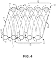
- alternating first sheets of filtration media 50 and second sheets of filtration media 60 are layered such as shown in FIG. 4 , which depicts two layers.
- FIG. 4 is a perspective view of a media pack where the first sheet of filtration media 50 of FIG. 2 is stacked on the second sheet of filtration media 60 of FIG. 3 .
- the curvature of the flutes on the second sheet of filtration media 60 is depicted through the first sheet of filtration media 50 for clarity.
- the first plurality of flutes 52 of the first sheet of filtration media 50 are non-parallel to the second plurality of flutes 62 of the second sheet of filtration media 60.
- the first plurality of flutes 52 form first curves and the second plurality of flutes 63 form second curves.
- the curvature pitch of the first curves is opposite the curvature pitch of the second curves.
- the first sheet of filtration media 50 contacts the second sheet of filtration media 60 at a discrete point 70.
- each first flute valley 59 contacts one second flute peak 68 at a discrete point 70.
- at least one first flute valley 59 contacts one second flute peak 68 at two discrete points 70.
- at least one first flute valley contacts two second flute peaks.
- at least one first flute valley contacts three second flute peaks.
- at least one first flute valley contacts four second flute peaks.
- at least one first flute valley contacts four second flute peaks but less than ten second flute peaks.
- first media sheet 50 and the second media sheet 60 are secured along a third edge 27 and a fourth edge 28, corresponding to a third side 36 and a fourth side 38 of the filter element depicted in FIG. 1 .
- the first sheet of filtration media 50 and the second sheet of filtration media 60 can be secured with an adhesive, such as a bead of glue or through other approaches, which obstructs fluid from passing between the third edge and fourth edge of the media pack.
- the first plurality of flutes 52 and second plurality of flutes 62 cumulatively define, as an example, an upstream portion of the fluid pathway 12 between the first media sheet 50 and the second media sheet 60 from the first face 20 towards the second face 30 of the media pack.
- An obstruction 72 is disposed between the first media sheet 50 and the second media sheet 60 such that the upstream portion of the fluid pathway 12 is obstructed towards the second face 30 of the media pack so that fluid flowing into the upstream portion of the fluid pathway (the "inlet") through the first face 20 passes through the first sheet of filtration media 50 and/or the second sheet of filtration media 60 to exit the media pack 15 through a downstream portion of the fluid pathway 12.
- first sheet of filtration media 50 and the second sheet of filtration media 60 are arranged in parallel along the fluid pathway 12 rather than in a series.
- downstream portion of the fluid pathway 12 (not shown) has an obstruction towards the first face 20 of the media pack between the first sheet of filtration media and the second sheet of filtration media.
- obstructions can be constructed through depositing an adhesive, such as a glue bead between the relevant adjacent media sheets.
- the filter element 10 depicted in FIG. 1 depicts an example where the pathways between alternating adjacent layers of media towards the upstream face (and towards downstream face, although not visible in the current view) have obstructions 23 so that fluids entering the first face 20 of the filtration media pack 15 pass through the filter media before exiting through the second face 30 of the media pack 15.
- FIGS. 5-7 depict an alternate configuration of alternating fluted media sheets consistent with the filter element 10 of FIG. 1 .
- FIG. 5 is a perspective view of a first sheet of filtration media 150 constructed and arranged in accordance with some implementations.
- the first sheet of filtration media 150 has a first plurality of parallel flutes 152 each extending between a first edge 154 and a second edge 156 of the first media sheet 150.
- the first edge 154 in the depicted embodiment corresponds to the first face 20 of filter element 10 ( FIG. 1 ), while second edge 156 corresponds to the second face 30 of the filter element 10 ( FIG. 1 ).
- the first plurality of flutes 152 extends between the first face 20 of the media pack and the second face 30 of the media pack 15.
- the first plurality of flutes 152 defines first flute peaks 158 and first flute valleys 159 extending between the first face 20 and the second face 30 of the media pack 15 (see FIG. 1 ).
- the first flute peaks 158 and the first flute valleys 159 protrude from opposite sides of the first sheet of filtration media 150.
- Each flute in the first plurality of flutes 152 is parallel to the remainder of flutes in the first plurality of flutes 152.
- the flutes in the first plurality of flutes 152 are substantially straight between the first face 20 and the second face 30 of the media pack of the filter element 10 ( FIG. 1 ).
- Substantially straight flutes as referenced herein generally means that each of the flute peaks defines a straight line along at least 90% or 95% of their respective lengths between the first face of the media pack and the second face of the media pack, which accounts for distortions that can occur at the flute ends when constructing a media pack, including pleated media packs which are discussed further herein.
- the flutes in the first plurality of flutes 152 are generally not perpendicular to the first face 20 of the media pack 15 and the second face 30 of the media pack 15. In some embodiments the flutes are angularly offset from the first face of the media pack and the second face of the media pack by at least 45 degrees but less than 90 degrees. In some embodiments, the flutes are angularly offset from the first face of the media pack and the second face of the media pack by 45-60 degrees, 60-75 degrees or 75-85 degrees. In some embodiments the flutes can be described as being angularly offset from the first edge 154 and the second edge 156 of the first sheet of filtration media 150.
- the flutes are angularly offset from the first edge 154 and the second edge 156 of the first sheet of filtration media 150 at least 45 degrees and less than 90 degrees. In some embodiments, the flutes are angularly offset from the first edge 154 and the second edge 156 of the first sheet of filtration media 150 by 45-60 degrees, 60-75 degrees or 75-85 degrees.
- the flutes in the first plurality of flutes 152 are perpendicular to the first face 20 of the media pack 15 and the second face 30 of the media pack 15 and/or the first edge 154 and the second edge 156 of the first sheet of filtration media 150.
- FIG. 6 is a perspective view of a second sheet of filtration media 160.
- the second sheet of filtration media 160 has a second plurality of parallel flutes 162 each extending between a first edge 164 and a second edge 166 of the second sheet of filtration media 160, and therefore extending between the first face 20 and the second face 30 of the filter element 10 ( FIG. 1 ).
- the second plurality of flutes 162 defines second flute peaks 168 and second flute valleys 169 extending between the first face 20 and the second face 30 of the media pack 15 (see FIG. 1 ).
- the second flute peaks 168 and the second flute valleys 169 protrude from opposite sides of the second sheet of filtration media 160.
- Each flute in the second plurality of flutes 162 is parallel to the remainder of flutes in the second plurality of flutes 162.
- the flutes in the second plurality of flutes 162 are substantially straight between the first face 20 and the second face 30 of the media pack 15 of the filter element 10 ( FIG. 1 ).
- the flutes in the second plurality of flutes 162 are not perpendicular to the first face 20 of the media pack 15 and the second face 30 of the media pack 15.
- the second plurality of flutes 162 can be angularly offset from the first face of the media pack and the second face of the media pack, and/or the first edge 164 and a second edge 166 of the second sheet of filtration media 1 60 by similar ranges discussed above with reference to FIG. 5 .
- the first plurality of flutes and the second plurality of flutes defined in the sheets of filtration media described herein can be configured to define fluid flow pathways through a filtration media pack.
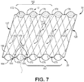
- alternating first sheets of filtration media 150 and second sheets of filtration media 160 are layered such as shown in FIG. 7 , which depicts two layers.
- FIG. 7 is a perspective view of a media pack where the first sheet of filtration sheet 150 of FIG. 5 is stacked on the second sheet of filtration media 160 of FIG. 6 .
- the extension of the flutes on the second sheet of filtration media 160 is depicted through the first sheet of filtration media 150 for clarity.
- the first plurality of flutes 152 of the first sheet of filtration media 150 are non-parallel to the second plurality of flutes 162 of the second sheet of filtration media 160.
- the first sheet of filtration media 150 generally contacts the second sheet of filtration media 160 at a discrete contact point 170.
- the first plurality of flutes 152 is angularly offset relative to the second plurality of flutes 162 by at least 5 degrees, where the offset angle ⁇ 1 can be measured between a valley 159 of the first sheet of filtration media 150 and a peak 168 of the second sheet of filtration media 160 at their respective contact point 170.
- the first plurality of flutes 152 is angularly offset relative to the second plurality of flutes 162 between 5 and 15 degrees.
- the first plurality of flutes 152 is angularly offset relative to the second plurality of flutes 162 by at least 10 degrees. In some embodiments, the first plurality of flutes 152 is angularly offset relative to the second plurality of flutes 162 between 15 and 30 degrees. In some embodiments, the first plurality of flutes 152 is angularly offset relative to the second plurality of flutes 162 by at least 20 degrees. The first plurality of flutes 152 is angularly offset relative to the second plurality of flutes 162 by less than 40 degrees in some constructions.
- each first flute valley 159 contacts one second flute peak 168 at a discrete contact point 170.
- at least one first flute valley 159 contacts two second flute peaks 168.
- at least one first flute valley contacts three second flute peaks.
- at least one first flute valley contacts four second flute peaks.
- at least one first flute valley contacts four second flute peaks but less than ten second flute peaks.
- first media sheet 150 and the second media sheet 160 are secured along a third edge 127 and a fourth edge 128, corresponding a the third side 36 and a fourth side 38 of the filter element 10 depicted in FIG. 1 .
- the first sheet of filtration media 150 and the second sheet of filtration media 160 can be secured with an adhesive, such as a bead of glue or through other approaches, which obstructs fluid from passing between the third edge 127 and fourth edge 128 of the media pack.
- the first plurality of flutes 152 and second plurality of flutes 162 cumulatively define, as an example, an upstream portion of the fluid pathway 12 between the first media sheet 150 and the second media sheet 160 from the first face 20 towards the second face 30 of the media pack.
- An obstruction 172 is disposed between the first media sheet 150 and the second media sheet 160 such that the upstream portion of the fluid pathway 12 is obstructed towards the second face 30 of the media pack such that fluid flowing into the upstream portion of the fluid pathway 12 (the "inlet") through the first face 20 passes through the first sheet of filter media 150 and/or the second sheet of filter media 160 to exit the media pack through a downstream portion of the fluid pathway 12.
- an obstruction 23 is disposed between the first media sheet 16 and the second media sheet 17 such that the downstream portion of the fluid pathway 12 is obstructed towards the first face 20 of the media pack 100.
- FIG. 8 is another example filter element 110 consistent with the technology disclosed herein.
- the filter elements 110 has a filtration media pack 115 and a seal member 140 extending around the periphery of the media pack 115.
- the filtration media pack 115 has a first face 120, a second face 130, and four side faces 132, 134, 136, 138.
- the first face 120 can be an inlet and the second face 130 can be an outlet.
- the filter element 110 is configured to be inserted into a housing (not shown) and fluids (such as an air stream) enter the filter element 10 at the first face 20, passes through the filtration media, and exits the filter element 110 at the second face 130 to define a fluid pathway 112.
- the media pack 115 of the filter element 110 has a plurality of first sheets of filtration media 151 and second sheets of filtration media 161 that can be referred to as media pleats.
- the current example media pack 115 is formed from a continuous web of filtration media, examples of which are depicted in FIGS. 9-17 and described below.
- the first sheets of filtration media 151 and the second sheets of filtration media 161 are separated by first set of pleat folds 180 and a second set of pleat folds 182.
- the first set of pleat folds 180 form obstructions between the first sheet of filtration media 151 and the second sheet of filtration media 161 towards the first face 120 of the media pack such that the fluid pathway extends through the first sheet of filtration media 151 and the second sheet of filtration media 161.
- the second set of pleat folds 182 form obstructions between the first sheet of filtration media 151 and the second sheet of filtration media 161 towards the second face 130 of the media pack such that the fluid pathway extends through the first sheet of filtration media 151 and the second sheet of filtration media 161.
- FIG. 9 depicts a continuous web of fluted media 200 constructed and arranged in accordance with some implementations, depicting the web of media 200 prior to being formed into a filtration media pack.
- the web of media 200 will be formed into a media pack, such as that shown in FIG. 8 .
- the embodiment shown in FIG. 9 of web of media 200 includes a plurality of alternating first filtration media sheets 250 and second filtration media sheets 260 that are separated by fold lines 280, 282 which define the locations of pleat folds.
- First fold lines 280 represents a first set of pleat folds and second fold lines 282 represent a second set of pleat folds, where the first set of pleat folds are configured to form a first face of a media pack and the second set of pleat folds are configured to form a second face of the media pack. While the fold lines 280, 282 in the current embodiment and throughout this application are depicted as straight, it should be understood that in various embodiments the fold lines deviate from a straight line to follow the flute profiles and reflect the flute peaks and valleys.
- a first sheet of filtration media 250 has a first plurality of parallel flutes 252 extending between first fold lines 280 and the second fold lines 282.
- the first plurality of flutes 252 defines first flute peaks 254 and first flute valleys 256.
- the first plurality of flutes 252 are curved between the first fold lines 280 and the second fold lines 282.
- the curvature of the flutes can be measured, for example, as the distance a flute peak extends out from an axis x 1 joining the peaks at the ends of the flute, such as distance D 2 depicted in FIG. 9 .
- the distance D 2 can be consistent with those described above regarding D 1 in FIG. 2 .
- a second sheet of filtration media 260 has a second plurality of parallel flutes 262 extending between first fold lines 280 and second fold lines 282.
- the second plurality of flutes 262 define second flute peaks 264 and second flute valleys 266.
- the second plurality of flutes 262 can have a curvature similar to the first plurality of flutes 252, and in some embodiments, including the one depicted, the second plurality of flutes 262 has an equal curvature as the first plurality of flutes 252 but in the opposite direction (see D 3 in FIG. 9 ).
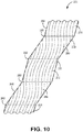
- the first sheets of filtration media 250 and the second sheets of filtration media 260 are folded upon one another at fold lines 280, 282 as shown in FIG. 10 , which is a perspective view of the web of fluted media 200 of FIG. 9 , with the web of media 200 scored and partially folded along the first fold lines 280 and the second fold lines 282.
- FIG. 11 the media is formed into a media pack 210.
- a portion of a first sheet of filtration media 250 is depicted torn away from the adjacent second sheet of filtration media 260 for clarity.
- a first set of pleat folds 280 form an inlet face 220
- a second set of pleat folds 282 form an outlet face 230
- filtration media extends between the first set of pleat folds 280 and the second set of pleat folds 282 to define a plurality of media pleats 240, where the media pleats are the first sheets of filtration media 250 and the second sheets of filtration media 260.
- the sheets of filtration media 250, 260 can be sealed along their pleat ends 258, 268, which refers to the edges of the sheets of filtration media 250, 260 that do not form the first set of pleat folds 280 or the second set of pleat folds 282.
- the plurality of flutes 252, 262 defined by each of the media pleats 240 extend between the inlet face 220 and the outlet face 230 of the media pack.
- the first plurality of flutes 252 and the second plurality of flutes 262 are non-parallel to reduce contact points between the sheets of filtration media 250, 260.
- each first flute valley 256 contacts one second flute peak at a discrete contact point.
- at least one first flute valley 256 contacts one second flute peak 266 at two discrete points.
- at least one first flute valley contacts two second flute peaks.
- at least one first flute valley contacts three second flute peaks.
- at least one first flute valley contacts four second flute peaks.
- at least one first flute valley contacts four second flute peaks but less than ten second flute peaks.
- the first plurality of flutes 252 form first curves
- the second plurality of flutes 262 form second curves
- the first curves have a curvature pitch that is the opposite of the curvature pitch of the second curves.
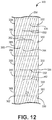
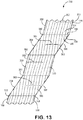
- FIG. 12 is a top plan view of another example web 300 of fluted media constructed and arranged in accordance with some implementations, prior to being formed into a filtration media pack.
- FIG. 13 depicts the web 300 of fluted media scored and partially folded
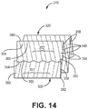
- FIG. 14 depicts the web 300 folded into a media pack 310.
- the media pack 310 can be incorporated in a filtration element, such as that shown in FIG. 8 .
- the web 300, and therefore the media pack 310 has alternating first sheets of filtration media 350 and a second sheets of filtration media 360 separated by fold lines 380, 382.
- a first sheet of filtration media 350 and the second sheet of filtration media 360 are continuous relative to each other and separated by a fold 380.
- the first sheet of filtration media 350 has a first plurality of parallel flutes 352 defining first flute peaks 354 and first flute valleys 356 extending between a first face 320 of the media pack 310 and the second face 330 of the media pack 310.
- the second sheet of filtration media 360 has a second plurality of parallel flutes 362 defining second flute peaks 364 and second flute valleys 366 extending between a first face 320 of the media pack 310 and the second face 330 of the media pack 310.
- the first sheet of filtration media 350 has first pleat ends 358 and the second sheet of filtration media 360 has second pleat ends 368, where the first pleat ends 358 and the second pleat ends 368 can be sealed.
- the first plurality of flutes 352 and the second plurality of flutes 362 are substantially straight.
- the flutes in the first plurality of flutes 352 are generally not perpendicular to the first face 320 of the media pack 310 and the second face 330 of the media pack 310, although in some other embodiments the flutes in the first plurality of flutes 352 are perpendicular to the first face 320 of the media pack 310 and the second face 330 of the media pack 310.
- the flutes in the second plurality of flutes 362 are generally not perpendicular to the first face 320 of the media pack 310 and the second face 330 of the media pack 310.
- the flute angle (see angle ⁇ 2 , in FIG. 12 , for example) can be measured between a flute peak 344 and a fold line 382, disregarding the ends of the flutes to the extent there are flute distortions resulting from folding the media along fold lines 380, 382.
- the respective flute angles of the first sheet 350 and second sheet 360 relative to a first fold line 380 and a second fold line 382 can have the same angle ranges as discussed above with reference to FIG. 5 between the flutes and the first edge 154 and second edge 156 of the sheet of filtration media.
- the first plurality of flutes 352 and the second plurality of flutes 362 are non-parallel.
- the first plurality of flutes 352 and the second plurality of flutes 362 can be angularly offset as described above with reference to FIG. 7 .
- each first flute valley 356 contacts one second flute peak 364 at a discrete contact point.
- each first flute valley 356 contacts one second flute peak 364 at a discrete point 370.
- at least one first flute valley 356 contacts two second flute peaks 364.
- at least one first flute valley contacts three second flute peaks.
- at least one first flute valley contacts four second flute peaks.
- at least one first flute valley contacts four second flute peaks but less than ten second flute peaks.
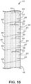
- FIG. 15 is a top plan view of a web of fluted media 400 constructed and arranged in accordance with an implementation.
- the web of media 400 is configured to be formed into a pleated filtration media pack 410 depicted in FIG. 17 .
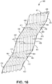
- FIG. 16 depicts the web of media 400 partially folded along fold lines 480, 482.
- the web of media 400, and therefore the media pack 410 has alternating first sheets of filtration media 450 and a second sheets of filtration media 460 separated by fold lines 480, 482.
- the fold lines 480, 482 are rotated slightly relative to the cross-web direction such that they are not perpendicular to the pleat ends 484 of the web of media 400.
- the first sheet of filtration media 450 has a first plurality of parallel flutes 452 defining first flute peaks 454 and first flute valleys 456 extending between a first face 420 of the pleated filtration media pack 410 and the second face 430 of the pleated filtration media pack 410.
- the second sheet of filtration media 460 has a second plurality of parallel flutes 462 defining second flute peaks 464 and second flute valleys 466 extending between a first face 420 of the media pack 410 and the second face 430 of the media pack 410.
- the first plurality of flutes 452 and the second plurality of flutes 462 are substantially straight.
- the flutes in the first plurality of flutes 452 are generally not perpendicular to the first face 420 of the media pack 410 and the second face 430 of the media pack 410, where the first face of the media pack 410 and the second face 430 of the media pack 410 are defined by first pleat folds 480 and second pleat folds 482, respectively.
- the flutes in the second plurality of flutes 462 are generally not perpendicular to the first face 420 of the media pack 410 and the second face 430 of the media pack 410.
- the first plurality of flutes 452 and the second plurality of flutes 462 are non-parallel in the media pack 410, although they are parallel on the web of filtration media 400.
- the first plurality of flutes 452 and the second plurality of flutes can be angularly offset as described above with reference to FIG. 7 .
- each first flute valley 456 contacts one second flute peak 464 at a discrete contact point.
- each first flute valley 458 contacts one second flute peak 468 at a discrete point 470.
- at least one first flute valley 456 contacts two second flute peaks 464.
- at least one first flute valley contacts three second flute peaks.
- at least one first flute valley contacts four second flute peaks.
- at least one first flute valley contacts four second flute peaks but less than ten second flute peaks.
- the media pack 410 of FIG. 17 has filtration media extends between the fold lines 480 in a back and forth arrangement of pleated media to define a plurality of media pleats.
- a plurality of flutes are defined by each of the media pleats, with the flutes having a length from one end of the flute to the opposite end of the flute, which extends between the inlet face 420 and outlet face 430 of the media pack 410.
- Pleat ends 484 of the filtration media extend from the inlet face 420 of the media pack to the outlet face 430 of the media pack forming a first side face 412 and second side face 414.
- the first side face 412 and second side face 414 are opposite from one another.
- each pleat of the media pack 410 defines the shape of a parallelogram.
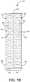
- FIG. 18 is a top plan view of a web of fluted media 500 constructed and arranged in accordance with some implementations.
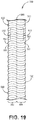
- FIG. 19 is a perspective view of the web of fluted media 500 of FIG. 18 in a scored and partially folded arrangement.
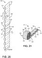
- FIG. 20 is a perspective view of the web of fluted media 500 in a folded arrangement
- FIG. 21 is a perspective view of a filter element 510 formed using the media of FIGS. 18 and 19 , where the media web 500 is folded along fold line 580 and rolled into a cylindrical media pack 515 for a filter element 510, with media edges 590, 592 defining a first face 520 of the filter element 510 and the pleat fold 580 defining a second face 530 of the filter element 510.
- the media has a wound cross-section.
- the filtration media web 500 has a first sheet of filtration media 550 and a second sheet of filtration media 560 and a central fold line 580.
- the first sheet of filtration media 550 and the second sheet of filtration media 560 are continuous and separated by a fold 580.
- the first sheet of filtration media 550 can define a first pleat 582 and the second sheet of filtration media 560 can define a second pleat 584.
- the fold 580 forms an obstruction between the first sheet of media 550 and the second sheet of filter media 560 to define a fluid pathway 512 extending between the first sheet of filtration media 550 and the second sheet of filtration media 560 and through the first sheet of filtration media 550 and the second sheet of filtration media 560 in parallel. While in FIG.
- the fluid pathway 512 is depicted as passing through the first sheet of filtration media 550, the fluid pathway 512 also extends through the second sheet of filtration media 560.
- An obstruction 572 seals the gaps between the outer surface of the first sheet of filtration media 550 and the outer surface of the second sheet of filtration media 560 similarly such that fluids passing through the first face 520 and second face 530 of the filter element 510 must first pass through the filtration media 515, which includes the first sheet of filtration media 550 and the second sheet of filtration media 560.
- the obstruction 572 can be positioned towards the first flow face 520 in some embodiments.
- An obstruction can also be disposed in any other gaps in the filter media to prevent fluid flow there-through, such as around the outer perimeter of the media pack and in a central opening of the wound media pack 510.
- the first sheet of filtration media 550 has a first plurality of parallel flutes 552 defining first flute peaks 554 and first flute valleys 556 extending between the first face 520 of the media pack 515 and a second face 530 of the media pack 515.
- the second sheet of filtration media 560 has a second plurality of parallel flutes 562 defining second flute peaks 564 and second flute valleys 566 extending between the first face 520 of the media pack 515 and a second face 530 of the media pack 515.
- the first plurality of flutes 552 are non-parallel to the second plurality of flutes 562.
- Each first flute valley 556 generally contacts one second flute peak 564 at a discrete contact point, and each flute valley 556 can contact additional second flute peaks 564 and possibly additional discrete contact points on particular second flute peaks 564 as has been described earlier in this application.
- first plurality of flutes 552 and the second plurality of flutes 562 are each curved.
- the curvature of the respective curves can be consistent with curvatures described above with reference to FIGS. 2-4 and 9-11 .
- the first plurality of flutes 552 and the second plurality of flutes 562 are substantially straight. In some such embodiments neither the first plurality of flutes nor the second plurality of flutes are perpendicular to the first face and the second face of the media pack.
- the first plurality of flutes 552 and the second plurality of flutes 562 are substantially straight, the first plurality of flutes 552 can be angularly offset from the second plurality of flutes 562 consistently with embodiments described above with reference to FIGS. 7 and 12-14 .
- first sheet of filtration media 550 and the second sheet of filtration media 560 are continuous and separated by a fold 580 in the current embodiment, in some other embodiments having a similarly cylindrical filter element construction the first sheet of filtration media 550 and the second sheet of filtration media 560 are discontinuous and joined together by an adhesive, for example.
- the first sheet of filtration media and the second sheet of filtration media both define either straight or curved flutes.
- the first sheet of filtration media defines straight flutes consistently with the descriptions of straight flutes herein
- the second sheet of filtration media defines curved flutes consistently with the descriptions of curved flutes herein.
- the performance of the filtration media pack can be altered or modified by selecting from several design criteria.
- performance generally refers to at least one of increased longevity, increased loading capacity, decreased pressure drop, increased flow, decreased size or volume, etc.
- the filtration media pack can be designed for a particular application to provide enhanced performance compared with certain presently available filtration media packs. Enhancing performance can result from, for example, controlling one or more of masking, flute width height ratio, flute length, flute density, flute shape, flute taper, and flute volume asymmetry. Any of these techniques can be used alone or in combination to provide a filtration media pack having desired properties.
- the fluid that can be filtered by the filtration media pack includes gaseous substance and liquid substances.
- gaseous substances that can be filtered includes air.
- liquid substances that can be filtered include water, oil, fuel, and hydraulic fluid.
- An example type of fluid to be filtered by the filtration media pack includes air. It should be understood, however, that the filtration media pack can be used to filter other gaseous substances and other liquid substances.
- the flutes contemplated by the technology disclosed herein can be tapered along their length.
- a taper refers to a reduction or an increase in the size of the flute along a length of the flute.
- filtration media that is tapered can exhibit a first set of flutes that decrease in size from a first end of the media to a second end of the media, and a second set of flutes that increase in size from the first end of the media to the second end of the media.
- Some filtration media can contain regions that are considered non-tapered and regions that are considered tapered along the flute length.
- each of the inlet and outlet can be generally planar, with the two parallel to one another.
- variations from this, for example non-planar faces are possible in some applications.
- the characterization of an inlet flow face and an opposite exit flow face is not a requirement that the inlet flow face and the outlet flow face are parallel.
- the inlet flow face and the exit flow face can, if desired, be provided as parallel to each other.
- the inlet flow face and the outlet flow face can be provided at an angle relative to each other so that the faces are not parallel.
- non-planar faces can be considered non-parallel faces.
- the reference to a pressure drop across the media refers to the pressure differential determined at a first face of the media relative to the pressure measured at second face of the media, wherein the first face and the second face are provided at generally opposite ends of a flute.
- the flute length can be decreased.
- the flute length refers to the distance from the first face of the filtration media to the second face of the filtration media.
- the flute length is greater than 0.9525 cm (.375 inches) alternatively greater than 1.27 cm (0.5 inches), greater than 2.54 cm (1 inches), or greater than 5.08 cm (2 inches).
- Example configurations have flute lengths of greater than 7.62 (3), greater than 10.16 (4), or greater than 15.24 cm (6 inches).
- the flute lengths are greater than 20.32 (8), 25.4 (10), or 30.48 cm (12 inches). In some constructions the flute lengths are less than 30.48 (12), less than 25.4 (10), less than 20.32 (8), less than 15.24 (6), less than 10.16 (4), or less than 5.08 cm (2 inches).
- the filtration media pack exhibits a flute density of 0.47-10.85 flutes/cm 2 (3-70 flutes/inch 2 ).
- filtration media pack has a flute density of 0.62-1.55 flutes/cm 2 (4-10 flutes/inch 2 ) or 3.10-9.30 flutes/cm 2 (20-60 flutes/inch 2 ).
- filtration media pack has a flute density of 4.65-7.75 flutes/cm 2 (30-50 flutes/inch 2 ).
- filtration media pack has a flute density of less than 10.85 flutes/cm 2 (70 flutes/inch 2 ).
- Some embodiments of the current technology can have flute volume asymmetry.
- Flute volume asymmetry refers to a volumetric difference within a filter element between the upstream volume and the downstream volume.
- the upstream volume refers to the volume between the sheets of filtration media that receives the unfiltered fluid
- the downstream volume refers to the volume between the sheets of filtration media that receives the filtered fluid that has passed through the filtration media from the upstream side. It can be desirable to provide a filtration element having an upstream volume that is greater than the downstream volume in some embodiments. It has been observed that in the case of filtering air, particulates in the air are deposited on the upstream side and, as a result, the capacity of the filtration media can be related to the volume of the upstream side. In some implementations, by providing volume asymmetry, it is possible to increase the volume available for receiving the incoming fluid and thereby increase the capacity of the media pack.
- Filtration media having a flute volume asymmetry exists when the difference between the upstream volume and the downstream volume is greater than 10%.
- media exhibiting flute volume asymmetry has flute volume asymmetry of greater than about 10%, greater than about 20%, greater than 30%, and preferably greater than about 50%.
- Exemplary ranges for flute volume asymmetry include about 30% to about 250%, and about 50% to about 200%.
- Filtration media having flute volume asymmetry can result from the presence of regular flutes or tapered flutes.
- media having relatively symmetric tapered flutes e.g., flutes tapering in each direction to relatively the same extent
- the existence or non-existence of tapered flutes does not imply or mean that existence or non-existence of an asymmetric volume arrangement.
- Media having a regular flute arrangement e.g., non-tapered
- Filtration media described herein can be constructed of various types of fibers and combinations of fibers.
- the filtration media has one or more of cellulose fibers, glass fibers, and polymeric fibers.
- the media can contain a resin. During the flute formation process, the media can be heated to above the glass transition point of the resin. When the resin cools, it will help to maintain the fluted shapes.
- the media can be provided with a fine fiber material on one or both sides thereof, for example in accord with U.S. Patent Nos. 6,955,775 , 6,673,136 , and 7,270,693 .
- fine fiber can be referred to as polymer fine fiber (microfiber and nanofiber) and can be provided on the media to improve filtration performance.
- polymer fine fiber microfiber and nanofiber
- the presence of fine fiber on media can provide enhanced filtration properties, provide for the use of thinner media, or both.
- Fiber characterized as fine fiber can have a diameter of about 0.001 micron to about 10 microns, about 0.005 micron to about 5 microns, or about 0.01 micron to about 0.5 micron.
- Nanofiber refers to a fiber having a diameter of less than 200 nanometer or 0.2 micron.
- Microfiber can refer to fiber having a diameter larger than 0.2 micron, but not larger than 10 microns.
- Exemplary materials that can be used to form the fine fibers include polyvinylidene chloride, polyvinyl alcohol polymers and co-polymers comprising various nylons such as nylon 6, nylon 4,6, nylon 6,6, nylon 6,10, and co-polymers thereof, polyvinyl chloride, PVDC, polystyrene, polyacrylonitrile, PMMA, PVDF, polyamides, and mixtures thereof.
Landscapes
- Chemical & Material Sciences (AREA)
- Chemical Kinetics & Catalysis (AREA)
- Filtering Of Dispersed Particles In Gases (AREA)
- Filtering Materials (AREA)
- Filtration Of Liquid (AREA)
Description
- The present disclosure is directed to filtration media, filtration media packs, and filtration elements. In particular, the disclosure is directed to filtration media containing flutes, and filtration media packs and elements formed with filtration media containing flutes.
- Fluid streams, such as gases and liquids, often carry contaminant material. In many instances, it is desired to filter some or all of the contaminant material from the fluid stream. For example, air flow streams to engines for motorized vehicles or for power generation equipment, gas streams to gas turbine systems, and air streams to various combustion furnaces, typically carry particulate contaminants that should be removed prior to delivery of the air flow to the vehicle, turbine, or combustion furnace. Also liquid streams in engine lubrication systems, hydraulic systems, coolant systems, and fuel systems often carry contaminants that should be removed from the liquid stream. It is desirable for such systems, that selected contaminant material be removed from (or have its level reduced in) the gaseous or liquid fluid. A variety of fluid filter arrangements have been developed for contaminant reduction. In general, however, continued improvements are sought. Known filtration media packs are for example disclosed in
JP S57 140618 A RU 2 438 754 C2 EP 1 990 510 A1WO 2005/077487 A1 . - The filtration media pack according to the present invention is defined in
independent claim 1. The current technology relates to a filtration media pack. The filtration media pack has a first sheet of filtration media and a second sheet of filtration media. The first sheet of filtration media has a first plurality of parallel flutes defining first flute valleys extending between a first face of the media pack and a second face of the media pack. The second sheet of filtration media has a second plurality of parallel flutes defining second flute peaks extending between the first face of the media pack and the second face of the media pack. The first plurality of flutes are non-parallel to the second plurality of flutes. Each first flute valley contacts one second flute peak at a discrete contact point. An obstruction between the first sheet of filtration media and the second sheet of filtration media defines a fluid pathway extending through the first sheet of filtration media and the second sheet of filtration media in parallel. - In some embodiments, at least one first flute valley contacts two second flute peaks. In some embodiments, at least one first flute valley contacts three second flute peaks. In some embodiments, at least one first flute valley contacts four second flute peaks. In some embodiments, at least one first flute valley contacts four second flute peaks but less than ten second flute peaks.
- Additionally or alternatively, each of the first plurality of flutes and the second plurality of parallel flutes are not perpendicular to the first face and the second face of the media pack. Additionally or alternatively, the first plurality of flutes is offset relative to the second plurality of flutes by at least 5 degrees. Additionally or alternatively, the first plurality of flutes is offset relative to the second plurality of flutes by at least 10 degrees. Additionally or alternatively, the first plurality of flutes is offset relative to the second plurality of flutes by at least 20 degrees.
- Each of the first plurality of flutes define a curve between the first face and the second face of the media pack. Additionally or alternatively, the curve of a peak of a flute in the first plurality of flutes extends outward from an axis joining the peak at each end of the flute by at least 5% of the flute length. Additionally or alternatively, the curve of a peak of a flute in the first plurality of flutes extends outward from an axis joining the peak at each end of the flute by at least 10% of the flute length. Additionally or alternatively, the curve of a peak of a flute in the first plurality of flutes extends outward from an axis joining the peak at each end of the flute by at least 20% of the flute length.
- The second plurality of flutes are curved. Additionally or alternatively, the first plurality of flutes form first curves, the second plurality of flutes form second curves, and the first curves have a curvature pitch that is opposite the curvature pitch of the second curves. Additionally or alternatively, the first sheet of filtration media and the second sheet of filtration media are continuous and separated by a fold. Additionally or alternatively, the first media sheet and the second media sheet define a cylindrical media pack with a wound cross-section. Additionally or alternatively, the first media sheet and the second media sheet are discontinuous. Additionally or alternatively, the first media sheet and the second media sheet define a cylindrical media pack with a wound cross-section. Additionally or alternatively, the obstruction is a glue bead between the first media sheet and second media sheet. Additionally or alternatively, the filtration media pack exhibits a flute density of at least about 6.20 flutes/cm2 (40 flutes/inch2).
- Additionally or alternatively, the media pack has an asymmetric volume arrangement such that an upstream volume of the media pack is greater than a downstream volume by at least 10%. Additionally or alternatively, the media pack has an asymmetric volume arrangement so that a volume on one side of the media pack is greater than a volume on another side of the media pack by at least 30%. Additionally or alternatively, the media pack has a seal member extending around a periphery of the media pack.
- In some embodiments, each of the first plurality of flutes defines a first flute peak extending between the inlet face and outlet face of the media pack, and each of the second plurality of flutes defines a second flute peak extending between the inlet face and outlet face of the media pack, and each first flute peak contacts one second flute peak at a discrete point. Additionally or alternatively, at least one first flute peak contacts two second flute valley. Additionally or alternatively, at least one first flute peak contacts three second flute valleys. Additionally or alternatively, at least one first flute peak contacts four second flute valleys. Additionally or alternatively, at least one first flute peak contacts two but less than ten second flute valleys.
- Additionally or alternatively, the first plurality of flutes is angularly offset relative to the second plurality of flutes by at least 5 degrees. Additionally or alternatively, the first plurality of flutes is angularly offset relative to the second plurality of flutes by at least 10 degrees. Additionally or alternatively, the first plurality of flutes is angularly offset relative to the second plurality of flutes by at least 20 degrees.
- Additionally or alternatively, the media pack has an asymmetric volume arrangement so that a volume on one side of the media pack is greater than a volume on another side of the media pack by at least 10%. Additionally or alternatively, the media pack has an asymmetric volume arrangement so that a volume on one side of the media pack is greater than a volume on another side of the media pack by at least 50%. Additionally or alternatively, the media pack has a seal member extending around a periphery of the media pack. Other embodiments are also disclosed.
- The above summary of the present technology is not intended to describe each disclosed embodiment of the present technology. This is the purpose of the detailed description and claims that follows.
- The filtration media, media packs, and element can be more completely understood in consideration of the following detailed description of various embodiments of the technology in connection with the accompanying drawings, in which:
-
FIG. 1 is perspective view of a filter element constructed and arranged in accordance with an implementation. -
FIG. 2 is a perspective view of a first sheet of filtration media constructed and arranged in accordance with an implementation. -
FIG. 3 is a perspective view of a second sheet of filtration media constructed and arranged in accordance with an implementation. -
FIG. 4 is a perspective view of the first and second sheets of filtration media ofFIG. 2 andFIG. 3 stacked with the first media sheet on top of the second media sheet, and the second media sheet shown partially in dashed lines. -
FIG. 5 is a perspective view of another example first fluted sheet of filtration media constructed and arranged in accordance with an implementation not forming part of the invention. -
FIG. 6 is a perspective view of another example second fluted sheet of filtration media constructed and arranged in accordance with an implementation not forming part of the invention. -
FIG. 7 is a perspective view of the third and fourth fluted media sheets ofFIG. 6 and FIG. 6 stacked with the third media sheet on top of the fourth media sheet, and the fourth media sheet shown partially in dashed lines. -
FIG. 8 is a perspective view of another example filter element consistent with the technology disclosed herein. -
FIG. 9 is a top plan view of a web of fluted media constructed and arranged in accordance with an implementation, the web for forming a filtration media pack. -
FIG. 10 is a perspective view of the web of fluted media ofFIG. 9 , showing the media scored and partially folded. -
FIG. 11 is a perspective view of a portion of a filtration media pack formed using the media ofFIG. 9 andFIG. 10 . -
FIG. 12 is a top plan view of a web of fluted media constructed and arranged in accordance with an implementation not forming part of the invention, the web for forming a filtration media pack. -
FIG. 13 is a perspective view of the web of fluted media ofFIG. 12 , constructed and arranged in accordance with an implementation not forming part of the invention, showing the media scored and partially folded. -
FIG. 14 is a perspective view of a portion of a filtration media pack not forming part of the invention, formed using the media ofFIG. 12 andFIG. 13 . -
FIG. 15 is a top plan view of a web of fluted media constructed and arranged in accordance with various implementations not forming part of the invention, the web for forming a filtration media pack. -
FIG. 16 is a perspective view of the web of fluted media ofFIG. 15 , constructed and arranged in accordance with various implementations not forming part of the invention, showing the media scored and partially folded. -
FIG. 17 is a perspective view of a portion of a filtration media pack, not forming part of the invention, formed using the media ofFIG. 15 andFIG. 16 . -
FIG. 18 is a top plan view of a web of fluted media constructed and arranged in accordance with various implementations, the web for forming a filtration media pack. -
FIG. 19 is a perspective view of the web of fluted media ofFIG. 18 , constructed and arranged in accordance with various implementations, showing the media scored and partially folded. -
FIG. 20 is a perspective view of the web of fluted media ofFIG. 18 , constructed and arranged in accordance with various implementations not forming part of the invention, showing the media folded. -
FIG. 21 is a perspective view of a filter element, not forming part of the invention, formed using the web of fluted media ofFIG. 18 andFIG. 19 . - The present application is directed to filtration media, media packs, and filtration elements. "Filtration media" is used herein to describe materials that are configured to filter fluids. "A sheet of filtration media" is defined as a portion of the filtration media that forms a single layer. "Media pack" refers to multiple sheets of the media in a layered configuration that cumulatively define an inlet, an outlet, and a fluid passageway extending from the inlet to the outlet through at least one sheet of media. "Filter element" refers to a media pack that is configured for installation into a system to filter fluids, typically with additional components such as a sealing member, support frame, handle, or other structures. "Flutes" as used herein is synonymous with the term "corrugations," which refers to a series of alternating elongate ridges/peaks, and elongate grooves/valleys.
- In some implementations, a sheet of fluted filtration media in a media pack defines flutes angularly offset from flutes defined on adjacent sheet(s) of fluted filtration media in the media pack such that the flutes intermittently contact flutes on adjacent sheet(s) of media. The flutes can be angled and curved flutes. In various other implementations, media packs consistent with the technology disclosed herein have a layered, fluted sheet construction with alternating pairs of sheets sealed towards an inlet face and an outlet face to define a fluid passageway from the inlet to the outlet through at least one sheet of filter media. In some implementation, media packs consistent with the technology disclosed herein are cylindrical having a wound cross section.
- The current technology relates to a filtration media pack. The filtration media pack has a first sheet of filtration media and a second sheet of filtration media. The first sheet of filtration media has a first plurality of parallel flutes defining first flute valleys extending between a first face of the media pack and a second face of the media pack. The second sheet of filtration media has a second plurality of parallel flutes defining second flute peaks extending between the first face of the media pack and the second face of the media pack. The first plurality of flutes are non-parallel to the second plurality of flutes. Each first flute valley contacts one second flute peak at a discrete contact point. An obstruction between the first sheet of filtration media and the second sheet of filtration media defines a fluid pathway extending through the first sheet of filtration media and the second sheet of filtration media in parallel.
- In some embodiments, at least one first flute valley contacts two second flute peaks. In some embodiments, at least one first flute valley contacts three second flute peaks. In some embodiments, at least one first flute valley contacts four second flute peaks. In some embodiments, at least one first flute valley contacts four second flute peaks but less than ten second flute peaks.
- Additionally or alternatively, each of the first plurality of flutes and the second plurality of parallel flutes are not perpendicular to the first face and the second face of the media pack. Additionally or alternatively, the first plurality of flutes is offset relative to the second plurality of flutes by at least 5 degrees. Additionally or alternatively, the first plurality of flutes is offset relative to the second plurality of flutes by at least 10 degrees. Additionally or alternatively, the first plurality of flutes is offset relative to the second plurality of flutes by at least 20 degrees.Each of the first plurality of flutes define a curve between the first face and the second face of the media pack. Additionally or alternatively, the curve of a peak of a flute in the first plurality of flutes extends outward from an axis joining the peak at each end of the flute by at least 5% of the flute length. Additionally or alternatively, the curve of a peak of a flute in the first plurality of flutes extends outward from an axis joining the peak at each end of the flute by at least 10% of the flute length. Additionally or alternatively, the curve of a peak of a flute in the first plurality of flutes extends outward from an axis joining the peak at each end of the flute by at least 20% of the flute length.
- Additionally or alternatively, the second plurality of flutes are curved. Additionally or alternatively, the first plurality of flutes form first curves, the second plurality of flutes form second curves, and the first curves have a curvature pitch that is opposite the curvature pitch of the second curves. Additionally or alternatively, the first sheet of filtration media and the second sheet of filtration media are continuous and separated by a fold. Additionally or alternatively, the first media sheet and the second media sheet define a cylindrical media pack with a wound cross-section. Additionally or alternatively, the first media sheet and the second media sheet are discontinuous. Additionally or alternatively, the first media sheet and the second media sheet define a cylindrical media pack with a wound cross-section. Additionally or alternatively, the obstruction is a glue bead between the first media sheet and second media sheet. Additionally or alternatively, the filtration media pack exhibits a flute density of at least about 6.20 flutes/cm2 (40 flutes/inch2).
- Additionally or alternatively, the media pack has an asymmetric volume arrangement such that an upstream volume of the media pack is greater than a downstream volume by at least 10%. Additionally or alternatively, the media pack has an asymmetric volume arrangement so that a volume on one side of the media pack is greater than a volume on another side of the media pack by at least 30%. Additionally or alternatively, the media pack has a seal member extending around a periphery of the media pack.
- In some embodiments, each of the first plurality of flutes defines a first flute peak extending between the inlet face and outlet face of the media pack, and each of the second plurality of flutes defines a second flute peak extending between the inlet face and outlet face of the media pack, and each first flute peak contacts one second flute peak at a discrete point. Additionally or alternatively, at least one first flute peak contacts two second flute valley. Additionally or alternatively, at least one first flute peak contacts three second flute valleys. Additionally or alternatively, at least one first flute peak contacts four second flute valleys. Additionally or alternatively, at least one first flute peak contacts two but less than ten second flute valleys.
- Additionally or alternatively, the first plurality of flutes is angularly offset relative to the second plurality of flutes by at least 5 degrees. Additionally or alternatively, the first plurality of flutes is angularly offset relative to the second plurality of flutes by at least 10 degrees. Additionally or alternatively, the first plurality of flutes is angularly offset relative to the second plurality of flutes by at least 20 degrees.
- Additionally or alternatively, the media pack has an asymmetric volume arrangement so that a volume on one side of the media pack is greater than a volume on another side of the media pack by at least 10%. Additionally or alternatively, the media pack has an asymmetric volume arrangement so that a volume on one side of the media pack is greater than a volume on another side of the media pack by at least 50%. Additionally or alternatively, the media pack has a seal member extending around a periphery of the media pack. Other embodiments are also disclosed.
- Referring now to the drawings,
FIG. 1 provides a perspective view of afilter element 10 constructed and arranged in accordance with an implementation. In this particular implementation, which is consistent with some embodiments, thefilter element 10 has amedia pack 15 having a plurality of sheets of filtration media including a first sheet offiltration media 16 and a second sheet offiltration media 17. Thefilter element 10 has afirst face 20, a second face 30 (opposite the first face 20), and four side faces 32, 34, 36, and 38. Thefirst face 20 can be an inlet and thesecond face 30 can be an outlet, although in some embodiments thefirst face 20 can be the outlet and thesecond face 30 can be the inlet. Aseal member 40 extends around a periphery of themedia pack 15. Theseal member 40 abuts the perimeter of thefirst face 20 adjacent to where the four side faces 32, 34, 36, and 38 converge at thefirst face 20. In some embodiments the seal member can project outward from thefirst face 20 or thesecond face 30. - The
filter element 10 is generally configured to be inserted into a housing and fluids to be filtered (such as an air stream) pass through afluid pathway 12 of thefilter element 10, entering at thefirst face 20 and exiting thefilter element 10 at thesecond face 30. As will be explained in more detail below in the discussion ofFIG. 4 , thefluid pathway 12 extends through the first sheet offiltration media 16 and/or the second sheet offiltration media 17 in parallel. - The
filter element 10 ofFIG. 1 is constructed of a plurality of alternatingfluted media sheets FIGS. 2 and3 , respectively. Specifically,FIG. 2 is a perspective view of a first sheet offiltration media 50 constructed and arranged in accordance with some implementations. The first sheet offiltration media 50 has a first plurality ofparallel flutes 52 each extending between afirst edge 54 and asecond edge 56 of thefirst media sheet 50. Thefirst edge 54 in the depicted embodiment corresponds to thefirst face 20 of the filter element 10 (FIG. 1 ), whilesecond edge 56 corresponds to thesecond face 30 of thefilter element 10. As such, the first plurality offlutes 52 extends between thefirst face 20 of themedia pack 15 and thesecond face 30 of themedia pack 15. - The first plurality of
flutes 52 defines first flute peaks 58 andfirst flute valleys 59 extending between thefirst face 20 and thesecond face 30 of the media pack 15 (seeFIG. 1 ). The first flute peaks 58 and thefirst flute valleys 59 protrude from opposite sides of the first sheet offiltration media 50. Each flute in the first plurality offlutes 52 is parallel to the remainder of flutes in the first plurality offlutes 52. Flutes are considered parallel when at least the flute peaks and the flute valleys are parallel. - The flutes in the first plurality of
flutes 52 are curved between thefirst face 20 and thesecond face 30 of the media pack 15 (FIG. 1 ). Curved flutes as referenced herein generally means that the flutes do not extend along a straight line between the first face of the media pack and the second face of the media pack. The flutes can define a single curve, such as depicted inFIG. 2 , or multiple curves between the first face and the second face of the media pack. The curvature of the flutes can be reflected by a "curvature pitch" measurement, for example, which is the maximum distance a flute peak extends out from a straight-line axis a joining the peaks at each end of the flute, such as distance C1 depicted inFIG. 2 . This curvature can be measured in absolute number (such as centimeters) or relative to the length L1 (seeFIG. 2 ) of the flute, where the length of a flute is measured along a flute peak from one end of the flute to the opposite end of the flute. For example, the curvature pitch can be at least 5%, 10%, or even 20% of the length L1 of the flute in certain embodiments. - In other examples, the curvature pitch can be characterized in terms of the "flute pitch" P1 (see
FIG. 2 ), which is the distance between adjacent peaks in the sheet offiltration media 50. In some embodiments the curvature pitch C1 can be at least 10% of the flute pitch P1 but less than 50 times the flute pitch P1. In some embodiments the curvature pitch C1 is between 10% and 50% of the flute pitch P1. In some embodiments the curvature pitch C1 is between 40% and 90% of the flute pitch P1. In some embodiments the curvature pitch C1 is between 80% and 200% of the flute pitch P1. In some embodiments the curvature pitch C1 is between 3 times and 10 times the flute pitch P1. In some embodiments the curvature pitch C1 is between 5 times and 20 times the flute pitch P1. In some embodiments the curvature pitch C1 is between 20 times and 50 times the flute pitch P1. -
FIG. 3 is a perspective view of a second sheet offiltration media 60 constructed and arranged in accordance with some implementations. The second sheet offiltration media 60 has a second plurality offlutes 62 extending between afirst edge 64 and asecond edge 66 of the second sheet of filtration media 60 (corresponding to thefirst face 20 and thesecond face 30 of themedia pack 15, as described above). The second plurality offlutes 62 defines second flute peaks 68 andsecond flute valleys 69 extending between thefirst face 20 and thesecond face 30 of the media pack 15 (FIG. 1 ). The second flute peaks 68 and thesecond flute valleys 69 protrude from opposite sides of the second sheet offiltration media 60. - In various embodiments, each flute in the second plurality of
flutes 62 is parallel to the remainder of flutes in the second plurality offlutes 62. The flutes in the second plurality offlutes 62 are curved between thefirst face 20 and thesecond face 30 of themedia pack 15. The curves can be consistent with configurations described above with reference toFIG. 2 . In some embodiments the curvature pitch of the second plurality offlutes 62 will be equal to the curvature pitch of the first plurality offlutes 52 but in the opposite direction of the first plurality offlutes 52. - The flutes defined in the sheets of filtration media described herein can be configured to define fluid flow pathways through a filtration media pack. To construct a filtration media pack, alternating first sheets of
filtration media 50 and second sheets offiltration media 60, for example, are layered such as shown inFIG. 4 , which depicts two layers. Specifically,FIG. 4 is a perspective view of a media pack where the first sheet offiltration media 50 ofFIG. 2 is stacked on the second sheet offiltration media 60 ofFIG. 3 . The curvature of the flutes on the second sheet offiltration media 60 is depicted through the first sheet offiltration media 50 for clarity. - The first plurality of
flutes 52 of the first sheet offiltration media 50 are non-parallel to the second plurality offlutes 62 of the second sheet offiltration media 60. The first plurality offlutes 52 form first curves and the second plurality of flutes 63 form second curves. In some embodiments the curvature pitch of the first curves is opposite the curvature pitch of the second curves. The first sheet offiltration media 50 contacts the second sheet offiltration media 60 at adiscrete point 70. Generally, eachfirst flute valley 59 contacts onesecond flute peak 68 at adiscrete point 70. In some embodiments, at least onefirst flute valley 59 contacts onesecond flute peak 68 at twodiscrete points 70. In some examples, at least one first flute valley contacts two second flute peaks. In some embodiments, at least one first flute valley contacts three second flute peaks. In some embodiments, at least one first flute valley contacts four second flute peaks. In some embodiments, at least one first flute valley contacts four second flute peaks but less than ten second flute peaks. - In various embodiments the
first media sheet 50 and thesecond media sheet 60 are secured along athird edge 27 and afourth edge 28, corresponding to athird side 36 and afourth side 38 of the filter element depicted inFIG. 1 . The first sheet offiltration media 50 and the second sheet offiltration media 60 can be secured with an adhesive, such as a bead of glue or through other approaches, which obstructs fluid from passing between the third edge and fourth edge of the media pack. - The first plurality of
flutes 52 and second plurality offlutes 62 cumulatively define, as an example, an upstream portion of thefluid pathway 12 between thefirst media sheet 50 and thesecond media sheet 60 from thefirst face 20 towards thesecond face 30 of the media pack. Anobstruction 72 is disposed between thefirst media sheet 50 and thesecond media sheet 60 such that the upstream portion of thefluid pathway 12 is obstructed towards thesecond face 30 of the media pack so that fluid flowing into the upstream portion of the fluid pathway (the "inlet") through thefirst face 20 passes through the first sheet offiltration media 50 and/or the second sheet offiltration media 60 to exit themedia pack 15 through a downstream portion of thefluid pathway 12. As such, the first sheet offiltration media 50 and the second sheet offiltration media 60 are arranged in parallel along thefluid pathway 12 rather than in a series. Similarly, the downstream portion of the fluid pathway 12 (not shown) has an obstruction towards thefirst face 20 of the media pack between the first sheet of filtration media and the second sheet of filtration media. Where the sheets of filter media are discontinuous, such as inFIG. 4 , obstructions can be constructed through depositing an adhesive, such as a glue bead between the relevant adjacent media sheets. - The
filter element 10 depicted inFIG. 1 depicts an example where the pathways between alternating adjacent layers of media towards the upstream face (and towards downstream face, although not visible in the current view) haveobstructions 23 so that fluids entering thefirst face 20 of thefiltration media pack 15 pass through the filter media before exiting through thesecond face 30 of themedia pack 15. -
FIGS. 5-7 depict an alternate configuration of alternating fluted media sheets consistent with thefilter element 10 ofFIG. 1 . Specifically,FIG. 5 is a perspective view of a first sheet offiltration media 150 constructed and arranged in accordance with some implementations. The first sheet offiltration media 150 has a first plurality ofparallel flutes 152 each extending between afirst edge 154 and asecond edge 156 of thefirst media sheet 150. Thefirst edge 154 in the depicted embodiment corresponds to thefirst face 20 of filter element 10 (FIG. 1 ), whilesecond edge 156 corresponds to thesecond face 30 of the filter element 10 (FIG. 1 ). As such, the first plurality offlutes 152 extends between thefirst face 20 of the media pack and thesecond face 30 of themedia pack 15. - The first plurality of
flutes 152 defines first flute peaks 158 andfirst flute valleys 159 extending between thefirst face 20 and thesecond face 30 of the media pack 15 (seeFIG. 1 ). The first flute peaks 158 and thefirst flute valleys 159 protrude from opposite sides of the first sheet offiltration media 150. Each flute in the first plurality offlutes 152 is parallel to the remainder of flutes in the first plurality offlutes 152. - The flutes in the first plurality of
flutes 152 are substantially straight between thefirst face 20 and thesecond face 30 of the media pack of the filter element 10 (FIG. 1 ). Substantially straight flutes as referenced herein generally means that each of the flute peaks defines a straight line along at least 90% or 95% of their respective lengths between the first face of the media pack and the second face of the media pack, which accounts for distortions that can occur at the flute ends when constructing a media pack, including pleated media packs which are discussed further herein. - In various embodiments the flutes in the first plurality of
flutes 152 are generally not perpendicular to thefirst face 20 of themedia pack 15 and thesecond face 30 of themedia pack 15. In some embodiments the flutes are angularly offset from the first face of the media pack and the second face of the media pack by at least 45 degrees but less than 90 degrees. In some embodiments, the flutes are angularly offset from the first face of the media pack and the second face of the media pack by 45-60 degrees, 60-75 degrees or 75-85 degrees. In some embodiments the flutes can be described as being angularly offset from thefirst edge 154 and thesecond edge 156 of the first sheet offiltration media 150. In some embodiments the flutes are angularly offset from thefirst edge 154 and thesecond edge 156 of the first sheet offiltration media 150 at least 45 degrees and less than 90 degrees. In some embodiments, the flutes are angularly offset from thefirst edge 154 and thesecond edge 156 of the first sheet offiltration media 150 by 45-60 degrees, 60-75 degrees or 75-85 degrees. - In at least some alternate embodiments the flutes in the first plurality of
flutes 152 are perpendicular to thefirst face 20 of themedia pack 15 and thesecond face 30 of themedia pack 15 and/or thefirst edge 154 and thesecond edge 156 of the first sheet offiltration media 150. -
FIG. 6 is a perspective view of a second sheet offiltration media 160. The second sheet offiltration media 160 has a second plurality ofparallel flutes 162 each extending between afirst edge 164 and asecond edge 166 of the second sheet offiltration media 160, and therefore extending between thefirst face 20 and thesecond face 30 of the filter element 10 (FIG. 1 ). The second plurality offlutes 162 defines second flute peaks 168 andsecond flute valleys 169 extending between thefirst face 20 and thesecond face 30 of the media pack 15 (seeFIG. 1 ). The second flute peaks 168 and thesecond flute valleys 169 protrude from opposite sides of the second sheet offiltration media 160. Each flute in the second plurality offlutes 162 is parallel to the remainder of flutes in the second plurality offlutes 162. - The flutes in the second plurality of
flutes 162 are substantially straight between thefirst face 20 and thesecond face 30 of themedia pack 15 of the filter element 10 (FIG. 1 ). The flutes in the second plurality offlutes 162 are not perpendicular to thefirst face 20 of themedia pack 15 and thesecond face 30 of themedia pack 15. The second plurality offlutes 162 can be angularly offset from the first face of the media pack and the second face of the media pack, and/or thefirst edge 164 and asecond edge 166 of the second sheet offiltration media 1 60 by similar ranges discussed above with reference toFIG. 5 . - The first plurality of flutes and the second plurality of flutes defined in the sheets of filtration media described herein can be configured to define fluid flow pathways through a filtration media pack. To construct a filtration media pack, alternating first sheets of
filtration media 150 and second sheets offiltration media 160, for example, are layered such as shown inFIG. 7 , which depicts two layers. Specifically,FIG. 7 is a perspective view of a media pack where the first sheet offiltration sheet 150 ofFIG. 5 is stacked on the second sheet offiltration media 160 ofFIG. 6 . The extension of the flutes on the second sheet offiltration media 160 is depicted through the first sheet offiltration media 150 for clarity. - The first plurality of
flutes 152 of the first sheet offiltration media 150 are non-parallel to the second plurality offlutes 162 of the second sheet offiltration media 160. The first sheet offiltration media 150 generally contacts the second sheet offiltration media 160 at adiscrete contact point 170. The first plurality offlutes 152 is angularly offset relative to the second plurality offlutes 162 by at least 5 degrees, where the offset angle α1 can be measured between avalley 159 of the first sheet offiltration media 150 and apeak 168 of the second sheet offiltration media 160 at theirrespective contact point 170. In some embodiments, the first plurality offlutes 152 is angularly offset relative to the second plurality offlutes 162 between 5 and 15 degrees. In some embodiments, the first plurality offlutes 152 is angularly offset relative to the second plurality offlutes 162 by at least 10 degrees. In some embodiments, the first plurality offlutes 152 is angularly offset relative to the second plurality offlutes 162 between 15 and 30 degrees. In some embodiments, the first plurality offlutes 152 is angularly offset relative to the second plurality offlutes 162 by at least 20 degrees. The first plurality offlutes 152 is angularly offset relative to the second plurality offlutes 162 by less than 40 degrees in some constructions. - Generally, each
first flute valley 159 contacts onesecond flute peak 168 at adiscrete contact point 170. In some examples, at least onefirst flute valley 159 contacts two second flute peaks 168. In some embodiments, at least one first flute valley contacts three second flute peaks. In some embodiments, at least one first flute valley contacts four second flute peaks. In some embodiments, at least one first flute valley contacts four second flute peaks but less than ten second flute peaks. - In various embodiments the
first media sheet 150 and thesecond media sheet 160 are secured along athird edge 127 and afourth edge 128, corresponding a thethird side 36 and afourth side 38 of thefilter element 10 depicted inFIG. 1 . The first sheet offiltration media 150 and the second sheet offiltration media 160 can be secured with an adhesive, such as a bead of glue or through other approaches, which obstructs fluid from passing between thethird edge 127 andfourth edge 128 of the media pack. - The first plurality of
flutes 152 and second plurality offlutes 162 cumulatively define, as an example, an upstream portion of thefluid pathway 12 between thefirst media sheet 150 and thesecond media sheet 160 from thefirst face 20 towards thesecond face 30 of the media pack. Anobstruction 172 is disposed between thefirst media sheet 150 and thesecond media sheet 160 such that the upstream portion of thefluid pathway 12 is obstructed towards thesecond face 30 of the media pack such that fluid flowing into the upstream portion of the fluid pathway 12 (the "inlet") through thefirst face 20 passes through the first sheet offilter media 150 and/or the second sheet offilter media 160 to exit the media pack through a downstream portion of thefluid pathway 12. Similarly, as is visible in the embodiment depicted inFIG. 1 and previously described, anobstruction 23 is disposed between thefirst media sheet 16 and thesecond media sheet 17 such that the downstream portion of thefluid pathway 12 is obstructed towards thefirst face 20 of the media pack 100. -
FIG. 8 is anotherexample filter element 110 consistent with the technology disclosed herein. Thefilter elements 110 has afiltration media pack 115 and aseal member 140 extending around the periphery of themedia pack 115. Thefiltration media pack 115 has afirst face 120, asecond face 130, and four side faces 132, 134, 136, 138. Thefirst face 120 can be an inlet and thesecond face 130 can be an outlet. Thefilter element 110 is configured to be inserted into a housing (not shown) and fluids (such as an air stream) enter thefilter element 10 at thefirst face 20, passes through the filtration media, and exits thefilter element 110 at thesecond face 130 to define a fluid pathway 112. - The
media pack 115 of thefilter element 110 has a plurality of first sheets offiltration media 151 and second sheets offiltration media 161 that can be referred to as media pleats. However, unlike the media packs previously described, the currentexample media pack 115 is formed from a continuous web of filtration media, examples of which are depicted inFIGS. 9-17 and described below. In such embodiments, the first sheets offiltration media 151 and the second sheets offiltration media 161 are separated by first set of pleat folds 180 and a second set of pleat folds 182. The first set of pleat folds 180 form obstructions between the first sheet offiltration media 151 and the second sheet offiltration media 161 towards thefirst face 120 of the media pack such that the fluid pathway extends through the first sheet offiltration media 151 and the second sheet offiltration media 161. Similarly, the second set of pleat folds 182 form obstructions between the first sheet offiltration media 151 and the second sheet offiltration media 161 towards thesecond face 130 of the media pack such that the fluid pathway extends through the first sheet offiltration media 151 and the second sheet offiltration media 161. -
FIG. 9 depicts a continuous web offluted media 200 constructed and arranged in accordance with some implementations, depicting the web ofmedia 200 prior to being formed into a filtration media pack. The web ofmedia 200 will be formed into a media pack, such as that shown inFIG. 8 . The embodiment shown inFIG. 9 of web ofmedia 200 includes a plurality of alternating firstfiltration media sheets 250 and secondfiltration media sheets 260 that are separated byfold lines lines 280 represents a first set of pleat folds andsecond fold lines 282 represent a second set of pleat folds, where the first set of pleat folds are configured to form a first face of a media pack and the second set of pleat folds are configured to form a second face of the media pack. While thefold lines - A first sheet of
filtration media 250 has a first plurality ofparallel flutes 252 extending betweenfirst fold lines 280 and the second fold lines 282. The first plurality offlutes 252 defines first flute peaks 254 andfirst flute valleys 256. In the current embodiment, which is consistent with some examples, the first plurality offlutes 252 are curved between thefirst fold lines 280 and the second fold lines 282. The curvature of the flutes can be measured, for example, as the distance a flute peak extends out from an axis x 1 joining the peaks at the ends of the flute, such as distance D2 depicted inFIG. 9 . The distance D2 can be consistent with those described above regarding D1 inFIG. 2 . - A second sheet of
filtration media 260 has a second plurality ofparallel flutes 262 extending betweenfirst fold lines 280 and second fold lines 282. The second plurality offlutes 262 define second flute peaks 264 andsecond flute valleys 266. The second plurality offlutes 262 can have a curvature similar to the first plurality offlutes 252, and in some embodiments, including the one depicted, the second plurality offlutes 262 has an equal curvature as the first plurality offlutes 252 but in the opposite direction (see D3 inFIG. 9 ). - The first sheets of
filtration media 250 and the second sheets offiltration media 260 are folded upon one another atfold lines FIG. 10 , which is a perspective view of the web offluted media 200 ofFIG. 9 , with the web ofmedia 200 scored and partially folded along thefirst fold lines 280 and the second fold lines 282. Upon further folding, as shown inFIG. 11 , the media is formed into amedia pack 210. A portion of a first sheet offiltration media 250 is depicted torn away from the adjacent second sheet offiltration media 260 for clarity. A first set of pleat folds 280 form aninlet face 220, a second set of pleat folds 282 form anoutlet face 230, and filtration media extends between the first set of pleat folds 280 and the second set of pleat folds 282 to define a plurality ofmedia pleats 240, where the media pleats are the first sheets offiltration media 250 and the second sheets offiltration media 260. The sheets offiltration media filtration media flutes media pleats 240 extend between theinlet face 220 and theoutlet face 230 of the media pack. - The first plurality of
flutes 252 and the second plurality offlutes 262 are non-parallel to reduce contact points between the sheets offiltration media first flute valley 256 contacts one second flute peak at a discrete contact point. In some embodiments, at least onefirst flute valley 256 contacts onesecond flute peak 266 at two discrete points. In some examples, at least one first flute valley contacts two second flute peaks. In some embodiments, at least one first flute valley contacts three second flute peaks. In some embodiments, at least one first flute valley contacts four second flute peaks. In some embodiments, at least one first flute valley contacts four second flute peaks but less than ten second flute peaks. In some embodiments, the first plurality offlutes 252 form first curves, the second plurality offlutes 262 form second curves, and the first curves have a curvature pitch that is the opposite of the curvature pitch of the second curves. -
FIG. 12 is a top plan view of anotherexample web 300 of fluted media constructed and arranged in accordance with some implementations, prior to being formed into a filtration media pack.FIG. 13 depicts theweb 300 of fluted media scored and partially folded, andFIG. 14 depicts theweb 300 folded into amedia pack 310. Themedia pack 310 can be incorporated in a filtration element, such as that shown inFIG. 8 . Theweb 300, and therefore themedia pack 310, has alternating first sheets offiltration media 350 and a second sheets offiltration media 360 separated byfold lines filtration media 350 and the second sheet offiltration media 360 are continuous relative to each other and separated by afold 380. - The first sheet of
filtration media 350 has a first plurality ofparallel flutes 352 defining first flute peaks 354 andfirst flute valleys 356 extending between afirst face 320 of themedia pack 310 and thesecond face 330 of themedia pack 310. The second sheet offiltration media 360 has a second plurality ofparallel flutes 362 defining second flute peaks 364 andsecond flute valleys 366 extending between afirst face 320 of themedia pack 310 and thesecond face 330 of themedia pack 310. The first sheet offiltration media 350 has first pleat ends 358 and the second sheet offiltration media 360 has second pleat ends 368, where the first pleat ends 358 and the second pleat ends 368 can be sealed. The first plurality offlutes 352 and the second plurality offlutes 362 are substantially straight. - In some embodiments, the flutes in the first plurality of
flutes 352 are generally not perpendicular to thefirst face 320 of themedia pack 310 and thesecond face 330 of themedia pack 310, although in some other embodiments the flutes in the first plurality offlutes 352 are perpendicular to thefirst face 320 of themedia pack 310 and thesecond face 330 of themedia pack 310. The flutes in the second plurality offlutes 362 are generally not perpendicular to thefirst face 320 of themedia pack 310 and thesecond face 330 of themedia pack 310. - Additionally or alternatively, the flute angle (see angle α2, in
FIG. 12 , for example) can be measured between a flute peak 344 and afold line 382, disregarding the ends of the flutes to the extent there are flute distortions resulting from folding the media alongfold lines first sheet 350 andsecond sheet 360 relative to afirst fold line 380 and asecond fold line 382 can have the same angle ranges as discussed above with reference toFIG. 5 between the flutes and thefirst edge 154 andsecond edge 156 of the sheet of filtration media. - The first plurality of
flutes 352 and the second plurality offlutes 362 are non-parallel. The first plurality offlutes 352 and the second plurality offlutes 362 can be angularly offset as described above with reference toFIG. 7 . - The offset flute orientations result in flutes which contact one another at a flute peak and an adjacent flute valley. For example, generally each
first flute valley 356 contacts onesecond flute peak 364 at a discrete contact point. Generally, eachfirst flute valley 356 contacts onesecond flute peak 364 at a discrete point 370. In some examples, at least onefirst flute valley 356 contacts two second flute peaks 364. In some embodiments, at least one first flute valley contacts three second flute peaks. In some embodiments, at least one first flute valley contacts four second flute peaks. In some embodiments, at least one first flute valley contacts four second flute peaks but less than ten second flute peaks. -
FIG. 15 is a top plan view of a web offluted media 400 constructed and arranged in accordance with an implementation. The web ofmedia 400 is configured to be formed into a pleatedfiltration media pack 410 depicted inFIG. 17 .FIG. 16 depicts the web ofmedia 400 partially folded alongfold lines media 400, and therefore themedia pack 410, has alternating first sheets offiltration media 450 and a second sheets offiltration media 460 separated byfold lines media 400. - The first sheet of
filtration media 450 has a first plurality ofparallel flutes 452 defining first flute peaks 454 andfirst flute valleys 456 extending between afirst face 420 of the pleatedfiltration media pack 410 and thesecond face 430 of the pleatedfiltration media pack 410. The second sheet offiltration media 460 has a second plurality ofparallel flutes 462 defining second flute peaks 464 andsecond flute valleys 466 extending between afirst face 420 of themedia pack 410 and thesecond face 430 of themedia pack 410. The first plurality offlutes 452 and the second plurality offlutes 462 are substantially straight. - The flutes in the first plurality of
flutes 452 are generally not perpendicular to thefirst face 420 of themedia pack 410 and thesecond face 430 of themedia pack 410, where the first face of themedia pack 410 and thesecond face 430 of themedia pack 410 are defined by first pleat folds 480 and second pleat folds 482, respectively. The flutes in the second plurality offlutes 462 are generally not perpendicular to thefirst face 420 of themedia pack 410 and thesecond face 430 of themedia pack 410. The first plurality offlutes 452 and the second plurality offlutes 462 are non-parallel in themedia pack 410, although they are parallel on the web offiltration media 400. The first plurality offlutes 452 and the second plurality of flutes can be angularly offset as described above with reference toFIG. 7 . - The offset flute orientations result in flutes which contact one another in adjacent media pleats only at a flute peak and an adjacent flute valley. For example, generally each
first flute valley 456 contacts onesecond flute peak 464 at a discrete contact point. Generally, each first flute valley 458 contacts one second flute peak 468 at a discrete point 470. In some examples, at least onefirst flute valley 456 contacts two second flute peaks 464. In some embodiments, at least one first flute valley contacts three second flute peaks. In some embodiments, at least one first flute valley contacts four second flute peaks. In some embodiments, at least one first flute valley contacts four second flute peaks but less than ten second flute peaks. - The
media pack 410 ofFIG. 17 has filtration media extends between thefold lines 480 in a back and forth arrangement of pleated media to define a plurality of media pleats. A plurality of flutes are defined by each of the media pleats, with the flutes having a length from one end of the flute to the opposite end of the flute, which extends between theinlet face 420 andoutlet face 430 of themedia pack 410. Pleat ends 484 of the filtration media extend from theinlet face 420 of the media pack to theoutlet face 430 of the media pack forming afirst side face 412 andsecond side face 414. Thefirst side face 412 andsecond side face 414 are opposite from one another. Theinlet face 420 is substantially parallel with theoutlet face 430, while thefirst side face 412 is substantially parallel with thesecond side face 414; and wherein thefirst side face 412 intersects theinlet face 420 at an angle of less than 90°. Thus, in this configuration each pleat of themedia pack 410 defines the shape of a parallelogram. -
FIG. 18 is a top plan view of a web offluted media 500 constructed and arranged in accordance with some implementations.FIG. 19 is a perspective view of the web offluted media 500 ofFIG. 18 in a scored and partially folded arrangement.FIG. 20 is a perspective view of the web offluted media 500 in a folded arrangement, andFIG. 21 is a perspective view of afilter element 510 formed using the media ofFIGS. 18 and19 , where themedia web 500 is folded alongfold line 580 and rolled into acylindrical media pack 515 for afilter element 510, withmedia edges first face 520 of thefilter element 510 and thepleat fold 580 defining asecond face 530 of thefilter element 510. In the rolledcylindrical filter element 510, the media has a wound cross-section. - The
filtration media web 500 has a first sheet offiltration media 550 and a second sheet offiltration media 560 and acentral fold line 580. As such, the first sheet offiltration media 550 and the second sheet offiltration media 560 are continuous and separated by afold 580. The first sheet offiltration media 550 can define afirst pleat 582 and the second sheet offiltration media 560 can define asecond pleat 584. Thefold 580 forms an obstruction between the first sheet ofmedia 550 and the second sheet offilter media 560 to define afluid pathway 512 extending between the first sheet offiltration media 550 and the second sheet offiltration media 560 and through the first sheet offiltration media 550 and the second sheet offiltration media 560 in parallel. While inFIG. 20 thefluid pathway 512 is depicted as passing through the first sheet offiltration media 550, thefluid pathway 512 also extends through the second sheet offiltration media 560. Anobstruction 572 seals the gaps between the outer surface of the first sheet offiltration media 550 and the outer surface of the second sheet offiltration media 560 similarly such that fluids passing through thefirst face 520 andsecond face 530 of thefilter element 510 must first pass through thefiltration media 515, which includes the first sheet offiltration media 550 and the second sheet offiltration media 560. Theobstruction 572 can be positioned towards thefirst flow face 520 in some embodiments. An obstruction can also be disposed in any other gaps in the filter media to prevent fluid flow there-through, such as around the outer perimeter of the media pack and in a central opening of thewound media pack 510. - The first sheet of
filtration media 550 has a first plurality ofparallel flutes 552 defining first flute peaks 554 andfirst flute valleys 556 extending between thefirst face 520 of themedia pack 515 and asecond face 530 of themedia pack 515. The second sheet offiltration media 560 has a second plurality ofparallel flutes 562 defining second flute peaks 564 andsecond flute valleys 566 extending between thefirst face 520 of themedia pack 515 and asecond face 530 of themedia pack 515. The first plurality offlutes 552 are non-parallel to the second plurality offlutes 562. Eachfirst flute valley 556 generally contacts onesecond flute peak 564 at a discrete contact point, and eachflute valley 556 can contact additional second flute peaks 564 and possibly additional discrete contact points on particular second flute peaks 564 as has been described earlier in this application. - In the current example the first plurality of
flutes 552 and the second plurality offlutes 562 are each curved. In such embodiments, the curvature of the respective curves can be consistent with curvatures described above with reference toFIGS. 2-4 and9-11 . In some alternate embodiments, the first plurality offlutes 552 and the second plurality offlutes 562 are substantially straight. In some such embodiments neither the first plurality of flutes nor the second plurality of flutes are perpendicular to the first face and the second face of the media pack. In embodiments where the first plurality offlutes 552 and the second plurality offlutes 562 are substantially straight, the first plurality offlutes 552 can be angularly offset from the second plurality offlutes 562 consistently with embodiments described above with reference toFIGS. 7 and12-14 . - While the first sheet of
filtration media 550 and the second sheet offiltration media 560 are continuous and separated by afold 580 in the current embodiment, in some other embodiments having a similarly cylindrical filter element construction the first sheet offiltration media 550 and the second sheet offiltration media 560 are discontinuous and joined together by an adhesive, for example. - In embodiments depicted herein, the first sheet of filtration media and the second sheet of filtration media both define either straight or curved flutes. However, it will be appreciated that, in some embodiments, the first sheet of filtration media defines straight flutes consistently with the descriptions of straight flutes herein, and the second sheet of filtration media defines curved flutes consistently with the descriptions of curved flutes herein.
- The performance of the filtration media pack can be altered or modified by selecting from several design criteria. The term "performance" generally refers to at least one of increased longevity, increased loading capacity, decreased pressure drop, increased flow, decreased size or volume, etc. For example, the filtration media pack can be designed for a particular application to provide enhanced performance compared with certain presently available filtration media packs. Enhancing performance can result from, for example, controlling one or more of masking, flute width height ratio, flute length, flute density, flute shape, flute taper, and flute volume asymmetry. Any of these techniques can be used alone or in combination to provide a filtration media pack having desired properties.
- The fluid that can be filtered by the filtration media pack includes gaseous substance and liquid substances. Exemplary gaseous substances that can be filtered includes air. Exemplary liquid substances that can be filtered include water, oil, fuel, and hydraulic fluid. An example type of fluid to be filtered by the filtration media pack includes air. It should be understood, however, that the filtration media pack can be used to filter other gaseous substances and other liquid substances.
- In some embodiments the flutes contemplated by the technology disclosed herein can be tapered along their length. In general, a taper refers to a reduction or an increase in the size of the flute along a length of the flute. In general, filtration media that is tapered can exhibit a first set of flutes that decrease in size from a first end of the media to a second end of the media, and a second set of flutes that increase in size from the first end of the media to the second end of the media. Some filtration media can contain regions that are considered non-tapered and regions that are considered tapered along the flute length.
- In some instances, each of the inlet and outlet can be generally planar, with the two parallel to one another. However, variations from this, for example non-planar faces, are possible in some applications. Furthermore, the characterization of an inlet flow face and an opposite exit flow face is not a requirement that the inlet flow face and the outlet flow face are parallel. The inlet flow face and the exit flow face can, if desired, be provided as parallel to each other. Alternatively, the inlet flow face and the outlet flow face can be provided at an angle relative to each other so that the faces are not parallel. In addition, non-planar faces can be considered non-parallel faces.
- In general, the reference to a pressure drop across the media refers to the pressure differential determined at a first face of the media relative to the pressure measured at second face of the media, wherein the first face and the second face are provided at generally opposite ends of a flute.
- In order to provide a filtration media having a relatively high flute density while retaining a desired pressure drop, the flute length can be decreased. The flute length refers to the distance from the first face of the filtration media to the second face of the filtration media. In certain implementations, the flute length is greater than 0.9525 cm (.375 inches) alternatively greater than 1.27 cm (0.5 inches), greater than 2.54 cm (1 inches), or greater than 5.08 cm (2 inches). Example configurations have flute lengths of greater than 7.62 (3), greater than 10.16 (4), or greater than 15.24 cm (6 inches). Optionally the flute lengths are greater than 20.32 (8), 25.4 (10), or 30.48 cm (12 inches). In some constructions the flute lengths are less than 30.48 (12), less than 25.4 (10), less than 20.32 (8), less than 15.24 (6), less than 10.16 (4), or less than 5.08 cm (2 inches).
- In some embodiments the filtration media pack exhibits a flute density of at least 5.43 flute/cm2 (35.0 flute/inch2) according to the formula:

- Some embodiments of the current technology can have flute volume asymmetry. Flute volume asymmetry refers to a volumetric difference within a filter element between the upstream volume and the downstream volume. The upstream volume refers to the volume between the sheets of filtration media that receives the unfiltered fluid, and the downstream volume refers to the volume between the sheets of filtration media that receives the filtered fluid that has passed through the filtration media from the upstream side. It can be desirable to provide a filtration element having an upstream volume that is greater than the downstream volume in some embodiments. It has been observed that in the case of filtering air, particulates in the air are deposited on the upstream side and, as a result, the capacity of the filtration media can be related to the volume of the upstream side. In some implementations, by providing volume asymmetry, it is possible to increase the volume available for receiving the incoming fluid and thereby increase the capacity of the media pack.
- Filtration media having a flute volume asymmetry exists when the difference between the upstream volume and the downstream volume is greater than 10%. Optionally, media exhibiting flute volume asymmetry has flute volume asymmetry of greater than about 10%, greater than about 20%, greater than 30%, and preferably greater than about 50%. Exemplary ranges for flute volume asymmetry include about 30% to about 250%, and about 50% to about 200%.
- Filtration media having flute volume asymmetry can result from the presence of regular flutes or tapered flutes. Furthermore, media having relatively symmetric tapered flutes (e.g., flutes tapering in each direction to relatively the same extent), can provide media lacking flute volume asymmetry (less than 10% volume asymmetry). Accordingly, the existence or non-existence of tapered flutes does not imply or mean that existence or non-existence of an asymmetric volume arrangement. Media having a regular flute arrangement (e.g., non-tapered) may or may not exhibit an asymmetric volume arrangement.
- Filtration media described herein can be constructed of various types of fibers and combinations of fibers. In some embodiments the filtration media has one or more of cellulose fibers, glass fibers, and polymeric fibers. The media can contain a resin. During the flute formation process, the media can be heated to above the glass transition point of the resin. When the resin cools, it will help to maintain the fluted shapes.
- The media can be provided with a fine fiber material on one or both sides thereof, for example in accord with
U.S. Patent Nos. 6,955,775 ,6,673,136 , and7,270,693 . In general, fine fiber can be referred to as polymer fine fiber (microfiber and nanofiber) and can be provided on the media to improve filtration performance. As a result of the presence of fine fiber on the media, it may be possible or desirable to provide media having a reduced weight or thickness while obtaining desired filtration properties. Accordingly, the presence of fine fiber on media can provide enhanced filtration properties, provide for the use of thinner media, or both. Fiber characterized as fine fiber can have a diameter of about 0.001 micron to about 10 microns, about 0.005 micron to about 5 microns, or about 0.01 micron to about 0.5 micron. Nanofiber refers to a fiber having a diameter of less than 200 nanometer or 0.2 micron. Microfiber can refer to fiber having a diameter larger than 0.2 micron, but not larger than 10 microns. Exemplary materials that can be used to form the fine fibers include polyvinylidene chloride, polyvinyl alcohol polymers and co-polymers comprising various nylons such as nylon 6, nylon 4,6, nylon 6,6,nylon 6,10, and co-polymers thereof, polyvinyl chloride, PVDC, polystyrene, polyacrylonitrile, PMMA, PVDF, polyamides, and mixtures thereof.
Claims (15)
- A filtration media pack (15) comprising:a first sheet (50) of filtration media, the first sheet (50) of filtration media comprising a first plurality (52) of parallel flutes defining first flute valleys (59) extending between a first face (20) of the media pack (15) and a second face (30) of the media pack (15); anda second sheet (60) of filtration media, the second sheet (60) of filtration media comprising a second plurality (62) of parallel flutes defining second flute peaks (68) extending between the first face (20) of the media pack (15) and the second face (30) of the media pack (15), wherein each first flute valley (59) contacts one second flute peak (68) at a discrete contact point (70), and wherein the first plurality (52) of flutes are non-parallel to the second plurality (62) of flutes; andan obstruction (72) between the first sheet (50) of filtration media and the second sheet (60) of filtration media to define a fluid pathway (12) extending through the first sheet (50) of filtration media and the second sheet (60) of filtration media in parallel;characterized in that each of the first plurality (52) of flutes define a curve between the first face (20) and the second face (30) of the media pack (15); and in that the second plurality (62) of flutes are curved.
- The filtration media pack (15) of any of claims 1, wherein at least one first flute valley (59) contacts two second flute peaks (68).
- The filtration media pack (15) of any of claims 1-2, wherein at least one first flute valley (59) contacts three second flute peaks (68).
- The filtration media pack (15) of any of claims 1-3, wherein at least one first flute valley (59) contacts four second flute peaks (68).
- The filtration media pack (15) of any of claims 1-4, wherein at least one first flute valley (59) contacts four second flute peaks (68) but less than ten second flute peaks (68)
- The filtration media pack (15) of any of claims 1-5, wherein the curve of a peak of a flute in the first plurality (52) of flutes extends outward from an axis joining the peak at each end of the flute by at least 5% of the flute length.
- The filtration media pack (15) of any of claims 1-6, wherein the curve of a peak of a flute in the first plurality (52) of flutes extends outward from an axis joining the peak at each end of the flute by at least 10% of the flute length.
- The filtration media pack (15) of any of claims 1-7, wherein the curve of a peak of a flute in the first plurality (52) of flutes extends outward from an axis joining the peak at each end of the flute by at least 20% of the flute length.
- The filtration media pack (15) of any of claims 1-8, wherein the first plurality (52) of flutes form first curves, the second plurality (62) of flutes form second curves, and the first curves have a curvature pitch that is opposite the curvature pitch of the second curves.
- The filtration media pack (15) of any of claims 1-9, wherein the first sheet (50) of filtration media and the second sheet (60) of filtration media are continuous and separated by a fold.
- The filtration media pack (15) of any of claims 1-10, wherein the first media sheet (50) and the second media sheet (60) define a cylindrical media pack with a wound cross-section.
- The filtration media pack (15) of any of claims 1-9, wherein the first media sheet (50) and the second media sheet (60) are discontinuous.
- The filtration media pack (15) of any of claims 1-12, wherein the obstruction (72) is a glue bead between the first media sheet (50) and second media sheet (60).
- The filtration media pack (15) of any of claims 1-13, wherein the filtration media pack (15) exhibits a flute density of at least about 6.20 flutes/cm2 (40 flutes/inch2).
- The filtration media pack (15) of any of claims 1-14, wherein the media pack (15) has an asymmetric volume arrangement such that an upstream volume of the media pack (15) is greater than a downstream volume by at least 10%.
Applications Claiming Priority (2)
| Application Number | Priority Date | Filing Date | Title |
|---|---|---|---|
| US201762548639P | 2017-08-22 | 2017-08-22 | |
| PCT/US2018/046726 WO2019040324A1 (en) | 2017-08-22 | 2018-08-14 | Fluted filtration media, filtration media packs, and filtration elements |
Publications (2)
| Publication Number | Publication Date |
|---|---|
| EP3672709A1 EP3672709A1 (en) | 2020-07-01 |
| EP3672709B1 true EP3672709B1 (en) | 2021-10-06 |
Family
ID=63405499
Family Applications (1)
| Application Number | Title | Priority Date | Filing Date |
|---|---|---|---|
| EP18760238.8A Active EP3672709B1 (en) | 2017-08-22 | 2018-08-14 | Fluted filtration media, filtration media packs, and filtration elements |
Country Status (6)
| Country | Link |
|---|---|
| EP (1) | EP3672709B1 (en) |
| JP (1) | JP7254062B2 (en) |
| CN (1) | CN111278528B (en) |
| BR (1) | BR112020003534A2 (en) |
| MX (1) | MX2020001701A (en) |
| WO (1) | WO2019040324A1 (en) |
Families Citing this family (4)
| Publication number | Priority date | Publication date | Assignee | Title |
|---|---|---|---|---|
| CN114377478B (en) | 2016-08-16 | 2023-08-22 | 唐纳森公司 | Hydrocarbon Fluid-Water Separation |
| WO2018075385A1 (en) | 2016-10-20 | 2018-04-26 | Cummins Filtration Ip, Inc. | Interrupted, directional emboss of flat sheet |
| DE112017005542T5 (en) | 2016-12-15 | 2019-07-25 | Cummins Filtration Ip, Inc. | Tetrahedral filter media |
| KR20200119321A (en) | 2018-02-15 | 2020-10-19 | 도날드슨 컴파니, 인코포레이티드 | Filter media composition |
Family Cites Families (12)
| Publication number | Priority date | Publication date | Assignee | Title |
|---|---|---|---|---|
| JPS57140618A (en) * | 1981-02-25 | 1982-08-31 | Nippon Denso Co Ltd | Filter element |
| JPS6178215U (en) * | 1984-10-29 | 1986-05-26 | ||
| US7270693B2 (en) | 2000-09-05 | 2007-09-18 | Donaldson Company, Inc. | Polymer, polymer microfiber, polymer nanofiber and applications including filter structures |
| US6673136B2 (en) | 2000-09-05 | 2004-01-06 | Donaldson Company, Inc. | Air filtration arrangements having fluted media constructions and methods |
| US6743273B2 (en) | 2000-09-05 | 2004-06-01 | Donaldson Company, Inc. | Polymer, polymer microfiber, polymer nanofiber and applications including filter structures |
| WO2005077487A1 (en) * | 2004-02-10 | 2005-08-25 | Donaldson Company, Inc. | Media arrangement; filter constructions; and, methods |
| CN1968733B (en) * | 2004-04-30 | 2011-06-15 | 唐纳森公司 | Filter arrangements, housings, assemblies, and methods |
| EP1990510B1 (en) * | 2007-05-02 | 2010-04-07 | ACR Co., Ltd. | Carrier for exhaust-gas purification |
| US9808752B2 (en) | 2008-02-04 | 2017-11-07 | Donaldson Company, Inc. | Method and apparatus for forming fluted filtration media |
| EP2461884B1 (en) | 2009-08-03 | 2019-11-06 | Donaldson Company, Inc. | Method for forming fluted filtration media having tapered flutes |
| RU2438754C2 (en) * | 2010-07-06 | 2012-01-10 | Владимир Васильевич Овинкин | Self-bearing fluted filtration medium (versions) |
| CN106925051A (en) * | 2017-03-15 | 2017-07-07 | 广西华原过滤系统股份有限公司 | A kind of honeycomb fashion filters core |
-
2018
- 2018-08-14 MX MX2020001701A patent/MX2020001701A/en unknown
- 2018-08-14 BR BR112020003534-3A patent/BR112020003534A2/en active Search and Examination
- 2018-08-14 CN CN201880053900.9A patent/CN111278528B/en active Active
- 2018-08-14 JP JP2020501287A patent/JP7254062B2/en active Active
- 2018-08-14 WO PCT/US2018/046726 patent/WO2019040324A1/en unknown
- 2018-08-14 EP EP18760238.8A patent/EP3672709B1/en active Active
Also Published As
| Publication number | Publication date |
|---|---|
| JP7254062B2 (en) | 2023-04-07 |
| JP2023093478A (en) | 2023-07-04 |
| BR112020003534A2 (en) | 2020-09-01 |
| MX2020001701A (en) | 2020-03-20 |
| US20200360852A1 (en) | 2020-11-19 |
| WO2019040324A1 (en) | 2019-02-28 |
| JP2020531242A (en) | 2020-11-05 |
| CN111278528A (en) | 2020-06-12 |
| CN114984689A (en) | 2022-09-02 |
| EP3672709A1 (en) | 2020-07-01 |
| CN111278528B (en) | 2022-07-01 |
Similar Documents
| Publication | Publication Date | Title |
|---|---|---|
| JP6585137B2 (en) | Filter medium laminate, filter element, and method | |
| EP3672709B1 (en) | Fluted filtration media, filtration media packs, and filtration elements | |
| JP7018995B2 (en) | Filter media laminate | |
| JP6490777B2 (en) | Method and apparatus for forming fluted filtration media having tapered flutes | |
| JP5607624B2 (en) | One-side laminate in which filter media sheets with flutes are laminated on one side of a face-to-face filter media sheet, method for forming the same, and filter element | |
| JP6002652B2 (en) | Method and apparatus for forming filter media with flutes | |
| JP2011530402A5 (en) | ||
| JP2010517749A5 (en) | ||
| CN111465442B (en) | Filter assembly | |
| US12097459B2 (en) | Fluted filtration media, filtration media packs, and filtration elements | |
| JP7557001B2 (en) | Fluted filtration media, filtration media packs, and filtration elements | |
| CN114984689B (en) | Fluted filter media, filter media pack, and filter element | |
| CN113727771B (en) | Filter element, air cleaner assembly and method |
Legal Events
| Date | Code | Title | Description |
|---|---|---|---|
| STAA | Information on the status of an ep patent application or granted ep patent |
Free format text: STATUS: UNKNOWN |
|
| STAA | Information on the status of an ep patent application or granted ep patent |
Free format text: STATUS: THE INTERNATIONAL PUBLICATION HAS BEEN MADE |
|
| PUAI | Public reference made under article 153(3) epc to a published international application that has entered the european phase |
Free format text: ORIGINAL CODE: 0009012 |
|
| STAA | Information on the status of an ep patent application or granted ep patent |
Free format text: STATUS: REQUEST FOR EXAMINATION WAS MADE |
|
| 17P | Request for examination filed |
Effective date: 20200323 |
|
| AK | Designated contracting states |
Kind code of ref document: A1 Designated state(s): AL AT BE BG CH CY CZ DE DK EE ES FI FR GB GR HR HU IE IS IT LI LT LU LV MC MK MT NL NO PL PT RO RS SE SI SK SM TR |
|
| AX | Request for extension of the european patent |
Extension state: BA ME |
|
| DAV | Request for validation of the european patent (deleted) | ||
| DAX | Request for extension of the european patent (deleted) | ||
| STAA | Information on the status of an ep patent application or granted ep patent |
Free format text: STATUS: EXAMINATION IS IN PROGRESS |
|
| 17Q | First examination report despatched |
Effective date: 20210205 |
|
| GRAP | Despatch of communication of intention to grant a patent |
Free format text: ORIGINAL CODE: EPIDOSNIGR1 |
|
| STAA | Information on the status of an ep patent application or granted ep patent |
Free format text: STATUS: GRANT OF PATENT IS INTENDED |
|
| INTG | Intention to grant announced |
Effective date: 20210506 |
|
| GRAS | Grant fee paid |
Free format text: ORIGINAL CODE: EPIDOSNIGR3 |
|
| GRAA | (expected) grant |
Free format text: ORIGINAL CODE: 0009210 |
|
| STAA | Information on the status of an ep patent application or granted ep patent |
Free format text: STATUS: THE PATENT HAS BEEN GRANTED |
|
| AK | Designated contracting states |
Kind code of ref document: B1 Designated state(s): AL AT BE BG CH CY CZ DE DK EE ES FI FR GB GR HR HU IE IS IT LI LT LU LV MC MK MT NL NO PL PT RO RS SE SI SK SM TR |
|
| REG | Reference to a national code |
Ref country code: GB Ref legal event code: FG4D |
|
| REG | Reference to a national code |
Ref country code: CH Ref legal event code: EP Ref country code: AT Ref legal event code: REF Ref document number: 1435739 Country of ref document: AT Kind code of ref document: T Effective date: 20211015 |
|
| REG | Reference to a national code |
Ref country code: IE Ref legal event code: FG4D |
|
| REG | Reference to a national code |
Ref country code: DE Ref legal event code: R096 Ref document number: 602018024699 Country of ref document: DE |
|
| REG | Reference to a national code |
Ref country code: LT Ref legal event code: MG9D |
|
| REG | Reference to a national code |
Ref country code: NL Ref legal event code: MP Effective date: 20211006 |
|
| REG | Reference to a national code |
Ref country code: AT Ref legal event code: MK05 Ref document number: 1435739 Country of ref document: AT Kind code of ref document: T Effective date: 20211006 |
|
| PG25 | Lapsed in a contracting state [announced via postgrant information from national office to epo] |
Ref country code: RS Free format text: LAPSE BECAUSE OF FAILURE TO SUBMIT A TRANSLATION OF THE DESCRIPTION OR TO PAY THE FEE WITHIN THE PRESCRIBED TIME-LIMIT Effective date: 20211006 Ref country code: LT Free format text: LAPSE BECAUSE OF FAILURE TO SUBMIT A TRANSLATION OF THE DESCRIPTION OR TO PAY THE FEE WITHIN THE PRESCRIBED TIME-LIMIT Effective date: 20211006 Ref country code: FI Free format text: LAPSE BECAUSE OF FAILURE TO SUBMIT A TRANSLATION OF THE DESCRIPTION OR TO PAY THE FEE WITHIN THE PRESCRIBED TIME-LIMIT Effective date: 20211006 Ref country code: BG Free format text: LAPSE BECAUSE OF FAILURE TO SUBMIT A TRANSLATION OF THE DESCRIPTION OR TO PAY THE FEE WITHIN THE PRESCRIBED TIME-LIMIT Effective date: 20220106 Ref country code: AT Free format text: LAPSE BECAUSE OF FAILURE TO SUBMIT A TRANSLATION OF THE DESCRIPTION OR TO PAY THE FEE WITHIN THE PRESCRIBED TIME-LIMIT Effective date: 20211006 |
|
| PG25 | Lapsed in a contracting state [announced via postgrant information from national office to epo] |
Ref country code: IS Free format text: LAPSE BECAUSE OF FAILURE TO SUBMIT A TRANSLATION OF THE DESCRIPTION OR TO PAY THE FEE WITHIN THE PRESCRIBED TIME-LIMIT Effective date: 20220206 Ref country code: SE Free format text: LAPSE BECAUSE OF FAILURE TO SUBMIT A TRANSLATION OF THE DESCRIPTION OR TO PAY THE FEE WITHIN THE PRESCRIBED TIME-LIMIT Effective date: 20211006 Ref country code: PT Free format text: LAPSE BECAUSE OF FAILURE TO SUBMIT A TRANSLATION OF THE DESCRIPTION OR TO PAY THE FEE WITHIN THE PRESCRIBED TIME-LIMIT Effective date: 20220207 Ref country code: PL Free format text: LAPSE BECAUSE OF FAILURE TO SUBMIT A TRANSLATION OF THE DESCRIPTION OR TO PAY THE FEE WITHIN THE PRESCRIBED TIME-LIMIT Effective date: 20211006 Ref country code: NO Free format text: LAPSE BECAUSE OF FAILURE TO SUBMIT A TRANSLATION OF THE DESCRIPTION OR TO PAY THE FEE WITHIN THE PRESCRIBED TIME-LIMIT Effective date: 20220106 Ref country code: NL Free format text: LAPSE BECAUSE OF FAILURE TO SUBMIT A TRANSLATION OF THE DESCRIPTION OR TO PAY THE FEE WITHIN THE PRESCRIBED TIME-LIMIT Effective date: 20211006 Ref country code: LV Free format text: LAPSE BECAUSE OF FAILURE TO SUBMIT A TRANSLATION OF THE DESCRIPTION OR TO PAY THE FEE WITHIN THE PRESCRIBED TIME-LIMIT Effective date: 20211006 Ref country code: HR Free format text: LAPSE BECAUSE OF FAILURE TO SUBMIT A TRANSLATION OF THE DESCRIPTION OR TO PAY THE FEE WITHIN THE PRESCRIBED TIME-LIMIT Effective date: 20211006 Ref country code: GR Free format text: LAPSE BECAUSE OF FAILURE TO SUBMIT A TRANSLATION OF THE DESCRIPTION OR TO PAY THE FEE WITHIN THE PRESCRIBED TIME-LIMIT Effective date: 20220107 Ref country code: ES Free format text: LAPSE BECAUSE OF FAILURE TO SUBMIT A TRANSLATION OF THE DESCRIPTION OR TO PAY THE FEE WITHIN THE PRESCRIBED TIME-LIMIT Effective date: 20211006 |
|
| REG | Reference to a national code |
Ref country code: DE Ref legal event code: R097 Ref document number: 602018024699 Country of ref document: DE |
|
| PG25 | Lapsed in a contracting state [announced via postgrant information from national office to epo] |
Ref country code: SM Free format text: LAPSE BECAUSE OF FAILURE TO SUBMIT A TRANSLATION OF THE DESCRIPTION OR TO PAY THE FEE WITHIN THE PRESCRIBED TIME-LIMIT Effective date: 20211006 Ref country code: SK Free format text: LAPSE BECAUSE OF FAILURE TO SUBMIT A TRANSLATION OF THE DESCRIPTION OR TO PAY THE FEE WITHIN THE PRESCRIBED TIME-LIMIT Effective date: 20211006 Ref country code: RO Free format text: LAPSE BECAUSE OF FAILURE TO SUBMIT A TRANSLATION OF THE DESCRIPTION OR TO PAY THE FEE WITHIN THE PRESCRIBED TIME-LIMIT Effective date: 20211006 Ref country code: EE Free format text: LAPSE BECAUSE OF FAILURE TO SUBMIT A TRANSLATION OF THE DESCRIPTION OR TO PAY THE FEE WITHIN THE PRESCRIBED TIME-LIMIT Effective date: 20211006 Ref country code: DK Free format text: LAPSE BECAUSE OF FAILURE TO SUBMIT A TRANSLATION OF THE DESCRIPTION OR TO PAY THE FEE WITHIN THE PRESCRIBED TIME-LIMIT Effective date: 20211006 Ref country code: CZ Free format text: LAPSE BECAUSE OF FAILURE TO SUBMIT A TRANSLATION OF THE DESCRIPTION OR TO PAY THE FEE WITHIN THE PRESCRIBED TIME-LIMIT Effective date: 20211006 |
|
| PLBE | No opposition filed within time limit |
Free format text: ORIGINAL CODE: 0009261 |
|
| STAA | Information on the status of an ep patent application or granted ep patent |
Free format text: STATUS: NO OPPOSITION FILED WITHIN TIME LIMIT |
|
| 26N | No opposition filed |
Effective date: 20220707 |
|
| PG25 | Lapsed in a contracting state [announced via postgrant information from national office to epo] |
Ref country code: AL Free format text: LAPSE BECAUSE OF FAILURE TO SUBMIT A TRANSLATION OF THE DESCRIPTION OR TO PAY THE FEE WITHIN THE PRESCRIBED TIME-LIMIT Effective date: 20211006 |
|
| PG25 | Lapsed in a contracting state [announced via postgrant information from national office to epo] |
Ref country code: SI Free format text: LAPSE BECAUSE OF FAILURE TO SUBMIT A TRANSLATION OF THE DESCRIPTION OR TO PAY THE FEE WITHIN THE PRESCRIBED TIME-LIMIT Effective date: 20211006 |
|
| PG25 | Lapsed in a contracting state [announced via postgrant information from national office to epo] |
Ref country code: MC Free format text: LAPSE BECAUSE OF FAILURE TO SUBMIT A TRANSLATION OF THE DESCRIPTION OR TO PAY THE FEE WITHIN THE PRESCRIBED TIME-LIMIT Effective date: 20211006 |
|
| REG | Reference to a national code |
Ref country code: CH Ref legal event code: PL |
|
| PG25 | Lapsed in a contracting state [announced via postgrant information from national office to epo] |
Ref country code: LU Free format text: LAPSE BECAUSE OF NON-PAYMENT OF DUE FEES Effective date: 20220814 Ref country code: LI Free format text: LAPSE BECAUSE OF NON-PAYMENT OF DUE FEES Effective date: 20220831 Ref country code: CH Free format text: LAPSE BECAUSE OF NON-PAYMENT OF DUE FEES Effective date: 20220831 |
|
| REG | Reference to a national code |
Ref country code: BE Ref legal event code: MM Effective date: 20220831 |
|
| PG25 | Lapsed in a contracting state [announced via postgrant information from national office to epo] |
Ref country code: IT Free format text: LAPSE BECAUSE OF FAILURE TO SUBMIT A TRANSLATION OF THE DESCRIPTION OR TO PAY THE FEE WITHIN THE PRESCRIBED TIME-LIMIT Effective date: 20211006 |
|
| P01 | Opt-out of the competence of the unified patent court (upc) registered |
Effective date: 20230413 |
|
| PG25 | Lapsed in a contracting state [announced via postgrant information from national office to epo] |
Ref country code: IE Free format text: LAPSE BECAUSE OF NON-PAYMENT OF DUE FEES Effective date: 20220814 |
|
| PG25 | Lapsed in a contracting state [announced via postgrant information from national office to epo] |
Ref country code: BE Free format text: LAPSE BECAUSE OF NON-PAYMENT OF DUE FEES Effective date: 20220831 |
|
| PGFP | Annual fee paid to national office [announced via postgrant information from national office to epo] |
Ref country code: GB Payment date: 20230720 Year of fee payment: 6 |
|
| PGFP | Annual fee paid to national office [announced via postgrant information from national office to epo] |
Ref country code: FR Payment date: 20230720 Year of fee payment: 6 Ref country code: DE Payment date: 20230720 Year of fee payment: 6 |
|
| PG25 | Lapsed in a contracting state [announced via postgrant information from national office to epo] |
Ref country code: CY Free format text: LAPSE BECAUSE OF FAILURE TO SUBMIT A TRANSLATION OF THE DESCRIPTION OR TO PAY THE FEE WITHIN THE PRESCRIBED TIME-LIMIT Effective date: 20211006 |
|
| PG25 | Lapsed in a contracting state [announced via postgrant information from national office to epo] |
Ref country code: MK Free format text: LAPSE BECAUSE OF FAILURE TO SUBMIT A TRANSLATION OF THE DESCRIPTION OR TO PAY THE FEE WITHIN THE PRESCRIBED TIME-LIMIT Effective date: 20211006 Ref country code: HU Free format text: LAPSE BECAUSE OF FAILURE TO SUBMIT A TRANSLATION OF THE DESCRIPTION OR TO PAY THE FEE WITHIN THE PRESCRIBED TIME-LIMIT; INVALID AB INITIO Effective date: 20180814 |