EP3672539B1 - Kühlakkusystem - Google Patents
Kühlakkusystem Download PDFInfo
- Publication number
- EP3672539B1 EP3672539B1 EP18847522.2A EP18847522A EP3672539B1 EP 3672539 B1 EP3672539 B1 EP 3672539B1 EP 18847522 A EP18847522 A EP 18847522A EP 3672539 B1 EP3672539 B1 EP 3672539B1
- Authority
- EP
- European Patent Office
- Prior art keywords
- pack
- sam
- cold
- packs
- refrigerant
- Prior art date
- Legal status (The legal status is an assumption and is not a legal conclusion. Google has not performed a legal analysis and makes no representation as to the accuracy of the status listed.)
- Active
Links
Images


Classifications
-
- F—MECHANICAL ENGINEERING; LIGHTING; HEATING; WEAPONS; BLASTING
- F25—REFRIGERATION OR COOLING; COMBINED HEATING AND REFRIGERATION SYSTEMS; HEAT PUMP SYSTEMS; MANUFACTURE OR STORAGE OF ICE; LIQUEFACTION SOLIDIFICATION OF GASES
- F25D—REFRIGERATORS; COLD ROOMS; ICE-BOXES; COOLING OR FREEZING APPARATUS NOT OTHERWISE PROVIDED FOR
- F25D3/00—Devices using other cold materials; Devices using cold-storage bodies
- F25D3/02—Devices using other cold materials; Devices using cold-storage bodies using ice, e.g. ice-boxes
- F25D3/06—Movable containers
- F25D3/08—Movable containers portable, i.e. adapted to be carried personally
-
- A—HUMAN NECESSITIES
- A61—MEDICAL OR VETERINARY SCIENCE; HYGIENE
- A61F—FILTERS IMPLANTABLE INTO BLOOD VESSELS; PROSTHESES; DEVICES PROVIDING PATENCY TO, OR PREVENTING COLLAPSING OF, TUBULAR STRUCTURES OF THE BODY, e.g. STENTS; ORTHOPAEDIC, NURSING OR CONTRACEPTIVE DEVICES; FOMENTATION; TREATMENT OR PROTECTION OF EYES OR EARS; BANDAGES, DRESSINGS OR ABSORBENT PADS; FIRST-AID KITS
- A61F7/00—Heating or cooling appliances for medical or therapeutic treatment of the human body
- A61F7/10—Cooling bags, e.g. ice-bags
-
- A—HUMAN NECESSITIES
- A61—MEDICAL OR VETERINARY SCIENCE; HYGIENE
- A61F—FILTERS IMPLANTABLE INTO BLOOD VESSELS; PROSTHESES; DEVICES PROVIDING PATENCY TO, OR PREVENTING COLLAPSING OF, TUBULAR STRUCTURES OF THE BODY, e.g. STENTS; ORTHOPAEDIC, NURSING OR CONTRACEPTIVE DEVICES; FOMENTATION; TREATMENT OR PROTECTION OF EYES OR EARS; BANDAGES, DRESSINGS OR ABSORBENT PADS; FIRST-AID KITS
- A61F7/00—Heating or cooling appliances for medical or therapeutic treatment of the human body
- A61F7/02—Compresses or poultices for effecting heating or cooling
- A61F2007/0203—Cataplasms, poultices or compresses, characterised by their contents; Bags therefor
- A61F2007/0206—Cataplasms, poultices or compresses, characterised by their contents; Bags therefor containing organic solids or fibres
- A61F2007/0209—Synthetics, e.g. plastics
- A61F2007/0214—Polymers, e.g. water absorbing
-
- A—HUMAN NECESSITIES
- A61—MEDICAL OR VETERINARY SCIENCE; HYGIENE
- A61F—FILTERS IMPLANTABLE INTO BLOOD VESSELS; PROSTHESES; DEVICES PROVIDING PATENCY TO, OR PREVENTING COLLAPSING OF, TUBULAR STRUCTURES OF THE BODY, e.g. STENTS; ORTHOPAEDIC, NURSING OR CONTRACEPTIVE DEVICES; FOMENTATION; TREATMENT OR PROTECTION OF EYES OR EARS; BANDAGES, DRESSINGS OR ABSORBENT PADS; FIRST-AID KITS
- A61F7/00—Heating or cooling appliances for medical or therapeutic treatment of the human body
- A61F7/02—Compresses or poultices for effecting heating or cooling
- A61F2007/0203—Cataplasms, poultices or compresses, characterised by their contents; Bags therefor
- A61F2007/0215—Cataplasms, poultices or compresses, characterised by their contents; Bags therefor containing liquids other than water
- A61F2007/0219—Gels
-
- A—HUMAN NECESSITIES
- A61—MEDICAL OR VETERINARY SCIENCE; HYGIENE
- A61F—FILTERS IMPLANTABLE INTO BLOOD VESSELS; PROSTHESES; DEVICES PROVIDING PATENCY TO, OR PREVENTING COLLAPSING OF, TUBULAR STRUCTURES OF THE BODY, e.g. STENTS; ORTHOPAEDIC, NURSING OR CONTRACEPTIVE DEVICES; FOMENTATION; TREATMENT OR PROTECTION OF EYES OR EARS; BANDAGES, DRESSINGS OR ABSORBENT PADS; FIRST-AID KITS
- A61F7/00—Heating or cooling appliances for medical or therapeutic treatment of the human body
- A61F7/02—Compresses or poultices for effecting heating or cooling
- A61F2007/0225—Compresses or poultices for effecting heating or cooling connected to the body or a part thereof
- A61F2007/0228—Compresses or poultices for effecting heating or cooling connected to the body or a part thereof with belt or strap, e.g. with buckle
-
- A—HUMAN NECESSITIES
- A61—MEDICAL OR VETERINARY SCIENCE; HYGIENE
- A61F—FILTERS IMPLANTABLE INTO BLOOD VESSELS; PROSTHESES; DEVICES PROVIDING PATENCY TO, OR PREVENTING COLLAPSING OF, TUBULAR STRUCTURES OF THE BODY, e.g. STENTS; ORTHOPAEDIC, NURSING OR CONTRACEPTIVE DEVICES; FOMENTATION; TREATMENT OR PROTECTION OF EYES OR EARS; BANDAGES, DRESSINGS OR ABSORBENT PADS; FIRST-AID KITS
- A61F7/00—Heating or cooling appliances for medical or therapeutic treatment of the human body
- A61F7/02—Compresses or poultices for effecting heating or cooling
- A61F2007/0244—Compresses or poultices for effecting heating or cooling with layers
- A61F2007/026—Compresses or poultices for effecting heating or cooling with layers with a fluid absorbing layer
-
- A—HUMAN NECESSITIES
- A61—MEDICAL OR VETERINARY SCIENCE; HYGIENE
- A61F—FILTERS IMPLANTABLE INTO BLOOD VESSELS; PROSTHESES; DEVICES PROVIDING PATENCY TO, OR PREVENTING COLLAPSING OF, TUBULAR STRUCTURES OF THE BODY, e.g. STENTS; ORTHOPAEDIC, NURSING OR CONTRACEPTIVE DEVICES; FOMENTATION; TREATMENT OR PROTECTION OF EYES OR EARS; BANDAGES, DRESSINGS OR ABSORBENT PADS; FIRST-AID KITS
- A61F7/00—Heating or cooling appliances for medical or therapeutic treatment of the human body
- A61F7/10—Cooling bags, e.g. ice-bags
- A61F2007/108—Cold packs, i.e. devices to be cooled or frozen in refrigerator or freezing compartment
-
- A—HUMAN NECESSITIES
- A61—MEDICAL OR VETERINARY SCIENCE; HYGIENE
- A61F—FILTERS IMPLANTABLE INTO BLOOD VESSELS; PROSTHESES; DEVICES PROVIDING PATENCY TO, OR PREVENTING COLLAPSING OF, TUBULAR STRUCTURES OF THE BODY, e.g. STENTS; ORTHOPAEDIC, NURSING OR CONTRACEPTIVE DEVICES; FOMENTATION; TREATMENT OR PROTECTION OF EYES OR EARS; BANDAGES, DRESSINGS OR ABSORBENT PADS; FIRST-AID KITS
- A61F7/00—Heating or cooling appliances for medical or therapeutic treatment of the human body
- A61F7/02—Compresses or poultices for effecting heating or cooling
-
- F—MECHANICAL ENGINEERING; LIGHTING; HEATING; WEAPONS; BLASTING
- F25—REFRIGERATION OR COOLING; COMBINED HEATING AND REFRIGERATION SYSTEMS; HEAT PUMP SYSTEMS; MANUFACTURE OR STORAGE OF ICE; LIQUEFACTION SOLIDIFICATION OF GASES
- F25D—REFRIGERATORS; COLD ROOMS; ICE-BOXES; COOLING OR FREEZING APPARATUS NOT OTHERWISE PROVIDED FOR
- F25D2303/00—Details of devices using other cold materials; Details of devices using cold-storage bodies
- F25D2303/08—Devices using cold storage material, i.e. ice or other freezable liquid
- F25D2303/082—Devices using cold storage material, i.e. ice or other freezable liquid disposed in a cold storage element not forming part of a container for products to be cooled, e.g. ice pack or gel accumulator
-
- F—MECHANICAL ENGINEERING; LIGHTING; HEATING; WEAPONS; BLASTING
- F25—REFRIGERATION OR COOLING; COMBINED HEATING AND REFRIGERATION SYSTEMS; HEAT PUMP SYSTEMS; MANUFACTURE OR STORAGE OF ICE; LIQUEFACTION SOLIDIFICATION OF GASES
- F25D—REFRIGERATORS; COLD ROOMS; ICE-BOXES; COOLING OR FREEZING APPARATUS NOT OTHERWISE PROVIDED FOR
- F25D2303/00—Details of devices using other cold materials; Details of devices using cold-storage bodies
- F25D2303/08—Devices using cold storage material, i.e. ice or other freezable liquid
- F25D2303/085—Compositions of cold storage materials
-
- F—MECHANICAL ENGINEERING; LIGHTING; HEATING; WEAPONS; BLASTING
- F25—REFRIGERATION OR COOLING; COMBINED HEATING AND REFRIGERATION SYSTEMS; HEAT PUMP SYSTEMS; MANUFACTURE OR STORAGE OF ICE; LIQUEFACTION SOLIDIFICATION OF GASES
- F25D—REFRIGERATORS; COLD ROOMS; ICE-BOXES; COOLING OR FREEZING APPARATUS NOT OTHERWISE PROVIDED FOR
- F25D2331/00—Details or arrangements of other cooling or freezing apparatus not provided for in other groups of this subclass
- F25D2331/80—Type of cooled receptacles
- F25D2331/804—Boxes
Definitions
- the present invention relates to a system for dispensing refrigerant packs and a method for providing said refrigerant pack.
- WO 2010/138669 A1 US 3 951 127 A , US 3 574 271 A , GB 2 251 206 A , US 2006/173430 A1 discloses refrigerant pack of the prior art and their method of manufacturing.
- the system for dispensing refrigerant packs uses a pack with an absorbent material inside, and without refrigerant fluid.
- the absorbent material is a Super Absorbent Material (SAM) such as Super Absorbent Polymer (SAP).
- Super Absorbent Material and "SAM” are used throughout the present application and claims to mean an absorbent material for use inside a cold pack.
- the absorbent material is a Super Absorbent Material, optionally SAP (Super Absorbent Polymer).
- SAM pack in all its grammatical forms is used in the present application and claims to mean a pack, according to an example embodiment of the invention, containing absorbent material, and without refrigerant fluid.
- a method of providing a refrigerant pack including providing a waterproof SAM pack with SAM inside and without refrigerant fluid inside, adding refrigerant fluid to an inside of the SAM pack, thereby producing a refrigerant pack, and sealing the refrigerant pack.
- the sealing the refrigerant pack includes heat sealing the refrigerant pack. According to some embodiments of the invention, the sealing the refrigerant pack includes gluing refrigerant SAM pack.
- the adding refrigerant fluid to the inside of the SAM pack includes puncturing the SAM pack, injecting refrigerant fluid to the inside of the SAM pack, producing a refrigerant pack, and sealing the refrigerant pack.
- cooling the refrigerant pack producing a cold pack.
- the filling unit is arranged to perform the adding refrigerant fluid to the inside of the SAM pack through a side of the SAM pack.
- An ice pack or gel pack is a portable plastic sac filled with water, or refrigerant gel or fluid. For use the contents are frozen in a freezer. Both ice and other non-toxic refrigerants (mostly water) can absorb a considerable amount of heat before they warm above 0 °C, due to a high latent heat of fusion of water. These packs are commonly used to keep goods such as food, pharmaceuticals and medical supplies cool in portable coolers; as a cold compress to alleviate the pain of minor injuries; and in insulated shipping containers to keep products cool during transport.
- SAM pack in all its grammatical forms is used in the present application and claims to mean a pack, according to an example embodiment of the invention, containing absorbent material, and without refrigerant fluid.
- cold pack in all its grammatical forms, is used in the present specification and claims to mean a refrigerant pack at a specific temperature, whether frozen, cold, roomtemperature or hot, for use as a temperature-affecting pack.
- a pack may be cold - for cooling or maintaining cold, at room temperature for maintaining temperature in a Controlled Room Temperature (CRT) environment, and hot - for heating or maintaining heat.
- CRT Controlled Room Temperature
- a refrigerant pack has a heat capacity which may optionally be used for cooling or maintaining cold, for maintaining temperature in a Controlled Room Temperature (CRT) environment, and for heating or maintaining heat.
- CRT Controlled Room Temperature
- Super Absorbent Materials sometimes also called slush powder, can absorb and retain extremely large amounts of a fluid relative to their own mass.
- the SAM may include one or more of, by way of some non-limiting examples: a Super Absorbent Polymer (SAP) material; gelatin; SAP in pill form, a Carboxymethyl cellulose (CMC) based gel, or materials commonly known in the art.
- SAP Super Absorbent Polymer
- CMC Carboxymethyl cellulose
- the refrigerant fluid may include one or more of, by way of some non-limiting examples: water; de-ionized water, de-salinated water, anti-freeze fluid, treated water, and fluids commonly known in the art.
- the SAM pack includes a moisture absorbing laminate film.
- the pack includes water only with no SAP.
- SAM pack or cold pack are used, a person skilled in the art should also understand use of a pack which includes water only with no SAP.
- the SAM pack is waterproof, absorbing no water until water is introduced on purpose. Such embodiments potentially prevent a need to keep water and/or moisture away from the SAM packs, and potentially prevent the SAM packs getting heavy over time by absorbing moisture.
- the waterproof material includes plastic film, such as polyethylene.
- the material forming the pack is spun-woven and backed to a polyethylene film for prevention of moisture absorbance.
- the SAP is optionally a non-toxic CMC based gel.
- the SAM packs are sealed in a way which allows filling with water and re-sealing, producing refrigerant packs.
- the SAM pack is heat sealed, and the SAM pack is subsequently penetrated to allow filling with water, and re-sealed, producing a refrigerant pack.
- the SAM pack is mechanically sealed by pressure of filling.
- the pack When the SAM pack is filled with refrigerant fluid the pack changes shape and seals against fluid leakage.
- the SAM packs are not sealed.
- An aspect of some embodiments of the invention relates to taking a SAM pack with SAM inside, and without water inside, according to some embodiments of the invention, and dispensing cold packs on demand.
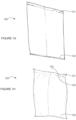
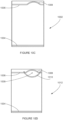
- FIGS 1I-K are simplified line drawing illustrations of cold packs according to some example embodiment of the invention.
- Figure 2B shows a system 280 which includes:
- the system 280 takes in input of material 281 such as, by way of a non-limiting example, plastic sheet, and produces output of a SAM pack 287.
- the material 281 is waterproof.
- the SAM packs 287 are connected to each other, forming a strip of SAM packs 287.
- the strip of SAM packs 287 is provided as a roll of SAM packs 287.
- a length of the strip of SAM packs 287 is greater than 20 meters, optionally 40 meters, optionally 100 meters, optionally 1,000 meters, optionally 10,000 meters.
- the strip of SAM packs 287 is provided as a fan-folded package of SAM packs 287.
- a box optionally includes 10,000 SAM packs sized 10x15 centimeters.
- 6 such boxes are packed on a pallet.
- 60,000 SAM packs are packed on a pallet.
- the SAM pack 287 is heat sealed.
- the SAM pack 287 is sealed using adhesive.
- the SAM pack 287 is optionally not sealed.
- the material 281 for forming the packs is a bag, such as a plastic bag, to be filled with SAM.
- the system 280 includes a forming unit 282 for optionally forming a bag from sheet material, and not forming a bag when the material 281 is already in a form of a bag.
- the material is a tube, such as a plastic tube.
- both open ends of the tube are sealed shut, by heating and/or by using adhesive to close the open ends.
- an amount of SAM placed in the bag is optionally selected, to potentially provide SAM packs with different cooling power, based on an amount of SAM within a SAM pack, and using a same pack size.
- the SAM placed in the bag is optionally SAM already packed in a cloth bag, and/or a mesh bag, and/or a woven bag, inserted into a waterproof bag.
- FIG. 2C is a simplified block diagram illustration of a system for producing a SAM pack according to an example embodiment of the invention.
- Figure 2C shows a system 240 which includes:
- system 240 is a Form Fill and Seal machine.
- the system 240 optionally forms the material 243 into a tube 234, and seals a seam 246 along a length of the tube 234.
- the system 240 optionally fills the tube 234 with SAM 244 in a desired amount, optionally using a dispenser (not shown), and seals 248 across the tube 234 to produce SAM packs 233.
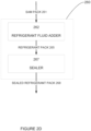
- FIG. 2D is a simplified block diagram illustration of a system for dispensing a refrigerant pack according to an example embodiment of the invention.
- Figure 2D shows a system 260 which includes:
- the refrigerant pack 265 is optionally not sealed.
- system 260 does not includes a sealer 267.
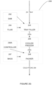
- FIG. 2E is a simplified flow chart illustration of a process for producing SAM packs and dispensing cold packs, according to an example embodiment of the invention.
- Figure 2E shows a method which includes:
- the adding refrigerant fluid is performed at a goods packing site.
- the SAM packs are optionally produced as strips or chains of connected SAM packs. In some embodiments the SAM packs are optionally produced from a tube, and the tube is sealed at ends of the SAM packs, producing a strip or chain of connected SAM packs.
- a strip or chain of SAM packs is packaged in a box. In some embodiments a strip or chain of SAM packs is packaged in a box in a fan-folded fashion, layer upon layer. In some embodiments a strip or chain of SAM packs is packaged in a roll.
- the SAM packs are a product which is shipped to users/clients. Shipping SAM packs takes up less weight and less volume than shipping cold packs which includes refrigerant fluid within each cold pack, and require only adding refrigerant fluid, even such as water, to become cold packs.
- the refrigerant fluid can weigh a large portion of a weight of the cold pack, and such weight is saved in SAM packs.
- a SAM pack, or a strip of SAM packs is optionally fed into a refrigerant injection machine.
- the refrigerant fluid is injected into an end, a side, or a face of a SAM pack.
- the refrigerant fluid is injected into the SAM pack by puncturing the SAM pack, optionally puncturing with a syringe for injection the refrigerant fluid into the SAM pack.
- the injection machine optionally also seals an opening through which the refrigerant fluid was injected.
- a component other than the injection machine optionally does the sealing of the opening through which the refrigerant fluid was injected.
- the strip of SAM packs is kept as a connected strip during the adding of refrigerant fluid. In some embodiments the strip of SAM packs is separated into separate packs by a same machine performing the adding of refrigerant fluid. In some embodiments the strip of SAM packs is separated into separate packs by a same machine performing the sealing or re-sealing of the packs.
- a strip of packs is separated into separate packs upon entry into the refrigeration machine and/or upon placing onto the conveyor.
- a strip of packs is separated into separate packs after a cooling, being separated when they are already cold packs.
- the conveyor is a conveyor travelling in a helical path, potentially reducing a footprint of the refrigeration machine.
- the conveyor is a conveyor travelling up in a helical path.
- an upward portion of the conveyor is optionally above a second conveyor, and is optionally used to dispense cold packs from above the second conveyor, optionally into a box on the second conveyor.
- an upward portion of the conveyor is optionally straight, optionally to convey above a second conveyor or above a storage container for the cold packs.
- the conveyor is a conveyor travelling down in a helical path.
- the cooling is performed by cold air enveloping the packs.
- a temperature of the air is optionally controllable, for example in a range between 0 and -40 degrees Celsius.
- the refrigeration machine can accommodate different sized packs.
- a pack reaching an end of the conveyor is dispensed, optionally via a dispensing chute.
- a pack reaching an end of the conveyor is optionally conveyed to a storage chamber for cold packs.
- the storage chamber is used to collect cold packs.
- cold packs are dispensed from the storage chamber when there is a demand for a cold pack, and if there is a cold pack in the storage chamber.
- the dispensing of cold packs is under computer control. In some embodiments the dispensing of cold packs is by a user entering a number of desired cold packs to a user interface. In some embodiments a data center controls requests for package shipments, and calculates and/or controls a number of cold packs to be dispensed.
- FIG. 2F is a simplified flow chart illustration of a process for providing a refrigerant pack according to an example embodiment of the invention.
- Figure 2F shows a method which includes:
- the refrigerant pack is not sealed.
- cold packs are made in two stages. In a first stage, plastic bags are filled with SAM, producing SAM packs, and shipped to a user. A second stage is performed at the user's site, where a machine makes cold packs out of the SAM packs. This is done by adding water to the SAM packs and cooling and/or freezing the packs. Since volume and weight of SAM packs with SAM only is significantly lower than fluid-filled cold packs, shipping, handling and storing costs are also significantly lower.
- SAM packs are made in a process called FFS, Form Fill and Seal.
- a sheet of plastic such as polyethylene, optionally from a roll of polyethylene sheet, is fed into a machine which makes packs, sacs or bags, fills SAM in each pack, producing SAM packs, and optionally seals the SAM pack.
- a thickness of the plastic sheet may vary between 80-300 microns.
- the SAM packs are connected to each other in a chain with or without perforation between consecutive SAM packs.
- a chain may include from 2 SAM packs up to 1,200-1,800 SAM packs.
- the FFS machine optionally packages each chain in a box, optionally fan-folded, layer upon layer, or as a roll.
- the SAM packs can be conveniently packaged in a roll because they are not as thick as cold packs which have refrigerant fluid inside.
- a wide range of SAM pack dimensions is made, to cover common sizes on the market.
- a typical width of a SAM pack may be 80-160 mm and a typical length may be 100-300 mm.
- a quantity of SAM per SAM pack is optionally determined by the pack size and by the pack's intended application, and is typically 1.0-2.0% of the weight of the bag after it is filled with water.
- a quantity of SAM per SAM pack is optionally determined by the pack size and by the pack's intended application, and is typically 5-10 grams of SAP per 500 cc water.
- data about SAM pack size, SAM amount, perforation between chains and number of SAM packs in a chain is optionally fed into a FFS machine for the manufacturing process. Feeding in the data is done either manually or by a computerized system.
- boxes with SAM packs or chains of SAM packs are optionally arranged on pallets and stored until delivered.
- a pallet may contain 5,000 to 100,000 and even to 250,000 SAM packs and more.
- pallets of boxes containing SAM packs or chains of SAM packs are delivered to users upon request or according to a predetermined schedule.
- SAM packs or chains of SAM packs are optionally fed into a refrigerant filling machine at the user's site, which injects refrigerant fluid such as water into the SAM packs.
- a refrigerant filling machine at the user's site, which injects refrigerant fluid such as water into the SAM packs.
- refrigerant fluid such as water
- an additional machine cools and/or freezes the packs, making cold packs.
- the cooling is to a temperature between +5° Celsius and -40° Celsius.
- the amount of water per cold pack may be in a range of 300-1,200 cc per pack.
- a quantity of refrigerant fluid per SAM pack is optionally determined by the pack size, manually set up or by a machine reading a barcode on the SAM pack.
- each pack is separated from a chain prior to being cooled.
- the cold packs can potentially be used in shipment of goods that require refrigeration.
- FIG. 2G is a simplified block diagram illustration of a system for producing a cold pack according to an example embodiment of the invention.
- Figure 2G shows a system 290 which includes:
- system 290 also includes a mixer (not shown) for mixing the SAM from the SAM supplying component 292 and the refrigerant fluid from the refrigerant fluid source 294 before filling the mixture into the tray 291.
- a mixer (not shown) for mixing the SAM from the SAM supplying component 292 and the refrigerant fluid from the refrigerant fluid source 294 before filling the mixture into the tray 291.
- the tray travels through the system 290 on a conveyor belt.
- the tray 291 includes compartments such as a home refrigerator ice tray.
- the tray 291 includes depressions in specific shapes, such as, by way of some non-limiting examples: cubic, rectangular, oval, spherical.
- the tray 296A containing the cold and/or frozen mixture contains the mixture frozen solid. In some embodiments the tray 296A containing the cold and/or frozen mixture contains the mixture as a cold slush or gel.
- the mixture is optionally frozen to the specific shape which, after packing in a bag, produces a bag with accurate dimensions as determined by the tray cell dimensions.
- the bag source 297 provides different size bags or packs, optionally based on receiving an electronic request for the different size bags or packs, and the system 290 provides cold packs in a variety of sizes.
- the packing component 298 is set up to pack a desired amount of cold and/or frozen mixture into the bags or packs, optionally based on receiving an electronic request for the desired amount and/or a request for different size bags or packs.
- the packing component 298 seals the cold packs 299.
- the packing component 298 is a Form Fill and Seal component.
- a controller 298A controls operation of the packing component 298.
- the packing component 298 does not seal the cold packs 299.
- the system 290 includes an additional optional sealer for sealing the cold packs 299.
- bag source 297 and the packing component 298 are in a separate machine from the other components described above with reference to the system 290.
- bag source 297 and the packing component 298 are optionally as described with reference to Figures 2B and 2C .
- the packs are provided as a connected series or strip of packs, and the packs are separated prior to filling with the cold and/or frozen mixture.
- the packs are provided as a connected series or strip of packs and the packs are separated after filling with the cold and/or frozen mixture.
- the packs are provided as a connected series or strip of packs and not separated after filling with the cold and/or frozen mixture.
- the packs are provided as separate packs packaged next to each other similarly to envelopes in a package of envelopes.
- FIG. 2H is a simplified block diagram illustration of a system for producing a cold pack according to an example embodiment of the invention.
- Figure 2H shows a system 1290 which includes:
- the tray travels through the system 1290 on a conveyor belt.
- the tray 1291 includes compartments such as a home refrigerator ice tray.
- the tray 1291 includes depressions in specific shapes, such as, by way of some non-limiting examples: cubic, rectangular, oval, spherical.
- the material in the SAM-plus-refrigerant-fluid filled tray 1295A is mixed by a mixing component (not shown) before refrigerating.
- the tray 1296A containing cold and/or frozen SAM plus fluid material contains material frozen solid. In some embodiments the tray 1296A containing cold and/or frozen SAM plus fluid material contains material as a cold slush.
- the bag source 1297 provides different size bags or packs, optionally based on receiving an electronic request for the different size bags or packs, and the system 1291 provides cold packs in a variety of sizes.
- the packing component 1298 is set up to pack a desired amount of cold and/or frozen SAM plus fluid material into the bags or packs, optionally based on receiving an electronic request for the desired amount and/or a request for different size bags or packs.
- the packing component 1298 seals the cold packs 1299.
- the packing component 1298 is a Form Fill and Seal component.
- the packing component 1298 does not seal the cold packs 1299.
- the system 1290 includes an additional optional sealer for sealing the cold packs 1299.
- bag source 1297 and the packing component 1298 are in a separate machine from the other components described above with reference to the system 1290.
- the packs are provided as a connected series or strip of packs, and the packs are separated prior to filling with the cold and/or frozen SAM plus fluid material.
- the packs are provided as a connected series or strip of packs and the packs are separated after filling with the cold and/or frozen SAM plus fluid material.
- the packs are provided as a connected series or strip of packs and not separated after filling with the cold and/or frozen SAM plus fluid material.
- the machines 290 1290 optionally receive a refrigerant pack, that is a SAM pack which also contains a refrigerant fluid, or a water-filled pack, and places the incoming pack(s) in a tray 291 1291.
- a manipulator picks up an incoming pack and places the pack in a cell in the tray 291 1291.
- the refrigerant pack is optionally shaped by the cell to any of the shapes listed above. a potential benefit of some embodiments includes forming cold packs which have a shape of the tray cells, potentially being formed with more accurate geometric dimensions than packs cooled or frozen without tray cell walls shaping them.
- the packs are shaped by a shape of the tray cell, optionally as a rectangular or brick shape.
- the tray is optionally interchangeable, enabling changing between different tray cell sizes and/or shapes.
- Figure 2I shows a system 1260 which includes:
- the fill component 1264 optionally accepts different size bags or packs, optionally based on receiving an electronic request for the different size bags or packs, and the system 1260 provides cold packs in a variety of sizes.
- the fill component 1264 is optionally set up to pack a desired amount of cold and/or frozen mixture into the bags or packs, optionally based on receiving an electronic request for the desired amount and/or a request for different size bags or packs.
- the fill component 1264 and the packing component 298 are a Form Fill and Seal component.
- a controller (not shown) controls operation of the system 1260.
- the packs are provided as a connected series or strip of packs, and the packs are separated prior to filling with the cold and/or frozen mixture.
- the packs are provided as a connected series or strip of packs and the packs are separated after filling with the cold and/or frozen mixture.
- the packs are provided as a connected series or strip of packs and not separated after filling with the cold and/or frozen mixture.
- cold pack batches are cooled to different temperatures.
- a first batch of cold packs is cooled to a first specific temperature, and optionally stored in a first holding unit or temperature controlled or insulated storage unit
- a second batch of cold packs is cooled to a second specific temperature, and optionally stored in a second holding unit or temperature controlled or insulated storage unit, or cold pack machine.
- Figure 3A is a simplified block diagram illustration of warehouse operation according to prior art.
- Figure 3A shows a warehouse 301 for shipping packages 308, at least some of which require addition of cold packs in order to maintain cold in the packages 308.
- the warehouse 301 includes an unloading dock 309A, a goods storage area 302, a cold pack freezer 303, and one or more conveyors 305 for packing some mixture of goods and cold packs, for shipping from a loading dock 309B.
- Trucks 306 unload goods 311 for storing at the goods storage area 302, and trucks 307 unload pallets 304 of cold packs for storing 312 in the cold pack freezer 303.
- warehouse operators or conveyors take goods 313 from the goods storage area 302 to the conveyors 305, and warehouse operators or conveyors (not shown) take 314 cold pack palettes 304 from the cold pack freezer 303 to use for packaging the goods 313 with cold packs. The packaged goods are then shipped by truck 309. Typically, a pallet 304 of 640 cold packs is placed next to the conveyors 305. Providing such a pallet 304 from the cold pack freezer 303 takes approximately 10-15 minutes, and is typically performed manually 12-15 times per day.
- Unloading a truck at the unloading dock 309A typically takes approximately an hour. Bringing in SAM packs instead of cold packs can reduce the volume and weight and numbers of trucks coming in, for a same amount of goods shipped, saving time and salary for the unloading. A number of empty cold pack boxes is greater than a number of empty SAM pack boxes.
- the cold pack freezer 303 takes up a large floor area.
- 55 pallets of cold packs include 2,200 cases of cold packs, which include 35,200 cold packs.
- a cold pack typically stays 2 weeks on the average in the freezer 303.
- the cold pack freezer requires power to refrigerate the cold packs, which arrived frozen/cold from a supplier of cold packs, and must be kept cold. Keeping a similar amount of SAM packs takes up less warehouse floor space and does not require refrigeration.
- 1 ⁇ 2 a pallet of SAM packs has a same number of SAM packs as 55 pallets of prior art cold packs of a similar size and/or cooling capacity.
- Refrigeration can optionally be used on-demand, to cool or freeze cold packs in the amount needed, without refrigerating a large number of cold packs for a long duration.
- FIG. 3B is a simplified block diagram illustration of warehouse operation according to an example embodiment of the invention.
- Figure 3B shows a warehouse 321 for shipping packages 328, at least some of which require addition of cold packs in order to maintain cold in the packages 328.
- the warehouse 321 includes an unloading dock 329A, a goods storage area 322, a SAM pack storage area 323, and one or more conveyors 325 for packing some mixture of goods and cold packs, for shipping from a loading dock 329B.
- Trucks 326 unload goods 331 for storing at the goods storage area 322, and trucks 327 unload pallets 324 of SAM packs for storing 330 in the SAM pack storage area 323.
- warehouse operators or conveyors take goods 341 from the goods storage area 322 to the packing lines and/or conveyors 325, and warehouse operators or conveyors (not shown) take 334 SAM pack pallets 324 from the SAM pack storage area 323 and place near one or more cold pack machines 340.
- the cold pack machines 340 optionally provide cold packs near the conveyors 325.
- the cold pack machines 340 optionally provide as many cold packs as are needed, optionally fulfilling computerized requests from a system which controls goods supply and/or from a user interface operated by warehouse operators working at the conveyors 325.
- goods and optionally cold packs have been packaged, optionally for shipping by truck 329.
- providing such a pallet 324 from the SAM pack storage area 323 is typically performed less than providing a pallet of cold packs 304 of Figure 3A , since the same number of SAM packs takes up much less volume and weight than cold packs, so a pallet 324 of SAM packs can contain many more packs than a pallet 304 of cold packs.
- a typical prior art pallet 304 contains about 640 cold packs, while a pallet of SAM packs may contain 5,000 to 100,000 SAM packs.
- the cold pack machines 340 optionally receive a strip of SAM packs, inject the SAM packs with refrigerant fluid such as water, cool or freeze the packs, and provide cold packs for packing with the goods.
- refrigerant fluid such as water, cool or freeze the packs
- Smaller trucks 327 may be used for providing the SAM packs, and/or same size trucks may be unloaded less often.
- Shipping a truckload of prior art cold packs may cost $1,500 to ship a distance of a day's drive. Such a cost potentially needs to be incurred far less, since a same volume and/or weight of shipping contains many times more SAM packs than prior art refrigerant packs or cold packs.
- An area of the SAM pack storage area 323 is significantly smaller than an area of the cold pack freezer 303.
- the SAM pack storage area may optionally use up an area of a few pallets, each pallet 48 inches by 48 inches, or 4 square feet.
- the floor space of the cold pack machine 340 is optionally approximately 40 square feet.
- a typical cold pack freezer 303 of Figure 3A can be as little as 3,000 cubic feet, taking up a floor space of more than 300 square feet, up to 40,000 cubic feet, taking up more than 4000 square feet.
- the warehouse 321 optionally includes a cold pack freezer 333. It is noted that the cold pack freezer 333 is not necessary in all embodiments since cold packs are produced in the cold pack machine(s) 340, and cold packs may be stored in cold pack machines 340 or in optional holding container included in the cold pack machines 340 or detachable from the cold pack machines 340.
- the cold pack freezer 333 may optionally contain cold packs left over and not used, optionally keeping the cold packs cold.
- the cold pack freezer 333 optionally serves to store cold packs at a first temperature when cold packs are being cooled by cold pack machines 340 to a second, different temperature.
- the cold pack freezer 333 used for serving the warehouse 321 is significantly smaller than the cold pack freezer 303 used for a prior art warehouse 301.
- FIG. 3C is a simplified flow chart illustration of a method for providing a cold pack in a packing line according to an example embodiment of the invention.
- Figure 3C shows a method which includes:
- the refrigerant pack is optionally not sealed.
- Figure 4A is a simplified flow chart illustration of a method for handling a request for goods delivery and determining a command for cold pack dispensing associated with the request, according to an example embodiment of the invention.
- Figure 4A shows a process which includes:
- the method optionally includes the cold pack dispenser dispensing cold packs based, at least in part, on the set of cold pack request parameters.
- the cold pack dispenser when a box with goods to be shipped reaches the cold pack dispenser, the right amount of packs is dispensed into the box.
- a user/packaging worker optionally makes an assessment of what set of cold pack request parameters should be used for a box or package, and feeds the parameters using a keyboard or a user interface to feed this set of parameters to the cold pack dispenser.
- Figure 4B is a simplified flow chart illustration of a method for analyzing goods contents in a goods shipping box and determining parameters for adding cold packs to the goods shipping box, according to an example embodiment of the invention.
- Figure 4B shows a process which includes:
- the receiving the data describing goods for packing in a goods shipping box comprises reading a barcode on the shipping box and interpreting the barcode to receive the data therefrom.
- the receiving the data describing goods for packing in a goods shipping box comprises using a camera to image the shipping box and/or contents of the shipping box, and using image analysis to determine the data, such as a size of the shipping box, number of goods, what portion of the shipping box is full, and additional data determined by the image analysis pertaining to the goods and/or the shipping box.
- FIG. 4C is a simplified flow chart illustration of a method for using a robot to pack goods and cold packs in a goods shipping box according to an example embodiment of the invention.
- Figure 4C shows a process which includes:
- the robot picks up the cold pack(s) from a cold pack machine as described herein.
- the robot sends a cold pack request or a goods request to a cold pack machine as described herein.
- the robot picks up cold pack(s) before picking up goods. In some embodiments the robot picks up goods before picking up cold pack(s).
- the robot places the goods into the goods shipping box before placing the cold packs. In some embodiments the robot places the cold packs into the goods shipping box before placing the goods. In some embodiments the robot intersperses placing the cold packs into the goods shipping box with placing the goods into the goods shipping box.
- additional steps of the robot sending a list of goods to a cold pack analysis module and/or the robot receiving data regarding cold pack parameters are optionally included.
- a person performs the operations which were described above as performed by the robot.
- the SAM packs are provided as a connected chain or strip of SAM packs.
- a sensor detects when a last pack in a chain or strip of packs enters a cold pack machine. In some embodiments a check is conducted when the last pack in a chain or strip of packs is detected to enter the cold pack machine.
- One or more sensor(s) optionally check an amount if ice accumulated on specific parts inside the machine. The checking is optionally done prior to feeding a new chain into the machine. In some embodiments, if ice is detected to have accumulated above an allowed quantity, the machine optionally blows warm or hot air to thaw the ice. In some embodiments melt water from the thawing is optionally accumulated in a container at a bottom of the machine, or fed to a drain pipe. In some embodiments the machine thaws the ice once every specific period of time. In some embodiments parts of the machine are checked for ice accumulation by shining light such as laser light off the parts.
- a refrigerant fluid injection needle is optionally monitored for correct operation, by way of a non-limiting example by measuring a pressure of fluid during injection, to verify that the needle is not blocked, or partially blocked.
- a pack is optionally monitored by a thermometer for pack temperature at one or more locations along a cooling and/or freezing path of a conveyor.
- a temperature inside a cooling/freezing machine is optionally monitored by a thermometer, at one or more locations along a cooling/freezing path of a conveyor.
- a speed of advance of a conveyor is optionally monitored, by way of a non-limiting example by measuring speed of servo motors advancing the conveyor, optionally using a PLC (Programmable Logic Controller).
- PLC Programmable Logic Controller
- a number of packs which are injected with refrigerant fluid is optionally controlled.
- the number of packs is optionally monitored by one or more of: a servo motor controller, measuring time, a manual count, a proximity sensor, and an optic sensor.
- a number of packs which are cooled/frozen is controlled.
- a speed of advance of a conveyor is optionally controlled, to optionally control a temperature of a cold pack, by way of a non-limiting example by measuring speed of servo motors advancing the conveyor, optionally using a PLC.
- a quantity of refrigerant fluid injected into a pack is optionally controlled.
- the control is according to bag size, as manually set up for an injector, as manually entered to a controller by an operator, or as read by a barcode reader reading a barcode on the pack.
- a time for cooling and/or freezing a cold pack is optionally controlled.
- the time is set according to bag size, as manually set up for a cooler/freezer, as manually entered to a cooler/freezer controller by an operator, as read by a barcode reader reading a barcode on the pack, or as calculated based on information about the pack size.
- a cold pack dispensing system and/or a warehouse which dispenses merchandise packed with cold packs optionally controls various amount parameters based on potential merchandise shipping and/or merchandise storage considerations.
- the amounts which are optionally controlled include one or more of:
- the considerations are performed automatically by a cold pack dispensing system or by a software program.
- the considerations are performed by modeling heat flow of an intended package.
- the considerations are performed by using a Look-Up-Table which includes one or more parameters listed in the amounts list and/or one or more parameters listed in the considerations list.
- the machine goes into a cold saving mode.
- the temperature inside the machine is optionally kept constant by blowing cold air into the machine.
- the cold air flows into the machine at specific time intervals.
- the cold air flows into the machine in response to one or more temperature sensor(s) sensing a temperature above a specific temperature.
- moving parts of the machine perform a back-and-forth movement to avoid seizure by ice.
- the machine may be empty of cold packs.
- a cooler and/or blower in the machine is optionally operated at full cooling power, until the cold packs reach a requested temperature.
- the refrigerator may optionally operate at a lower intensity.
- the machine may be at a desired temperature, and enter into an energy saving mode.
- a water injection needle is optionally monitored by one or more sensor(s). In some embodiments the water injection needle is optionally monitored to detect accumulation of scale in the water injection needle. In some embodiments the water injection needle is optionally monitored to detect accumulation of SAM blocking the water injection needle.
- scale on the injection needle is optionally monitored by laser sensors.
- scale on the injection needle is optionally monitored by monitoring a pressure required to push a syringe and/or by monitoring a speed of movement of a plunger of a syringe.
- the cold pack dispensing machine when the water injection needle is detected as requiring maintenance, the cold pack dispensing machine, or the fluid injection component, optionally sends a message to a machine control unit to replace the needle.
- a periodic replacement of the needle is performed.
- water filters are optionally checked for cleanliness at the beginning of each shift. In some embodiments, filters are replaced periodically.
- moving parts such as bearings, electric motors, blowers and the like are checked periodically and replaced when necessary.
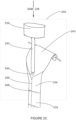
- FIG. 5A is a simplified block diagram illustration of a device which receives SAM packs and dispenses packs with refrigerant fluid or gel according to an example embodiment of the invention.
- Figure 5A shows some device components along a refrigerant filling path, from a SAM pack input 501 to dispensing a pack.
- a pack filler device 509 receives a SAM pack 503 from the SAM pack input 501.
- the SAM pack 503 enters the pack filler device 509.
- the pack filler device 509 optionally includes an injector 505, which injects refrigerant fluid into the SAM pack 503, producing a refrigerant pack 506.
- the pack filler device 509 also includes an optional pack sealer component 507, which optionally seals the injected pack, producing a sealed pack 511 with refrigerant fluid.
- the pack filler device 509 does not seal the injected pack, producing a not-sealed pack 511 with refrigerant fluid.
- FIG. 5B is a simplified block diagram illustration of a cold pack machine which takes in sealed packs and dispenses cold packs according to an example embodiment of the invention.
- Figure 5B shows a cold pack machine 535, which includes a conveyor 513 and a cooler and blower component 515.
- a sealed pack 511 with refrigerant fluid optionally enters onto, or optionally a user places onto, a conveyor 513 through the cold pack machine 535.
- the conveyor 513 carries the pack 511 through a cooler which cools the pack 511 to a desired temperature, producing a cold pack 521 525.
- the conveyor 513 dispenses the cold pack 521 optionally via an optional dispenser 523 as a cold pack 524.
- the cold pack 525 is stored in an optional storage unit 527, for optional dispensing later, for example by user taking the cold pack 525 from the storage unit 527, or by the storage unit 527 dispensing a cold pack in response to a computer command, optionally through the optional dispenser 523, or through another optional dispenser.
- the cold pack machine 535 of Figure 5B optionally includes the pack filler 509 as a component of the cold pack machine 535.
- Figure 5B also shows a cooler and blower 515 optionally blowing cold air 517 for cooling the packs 511 on the conveyor 513.
- the cold air 517 is collected and returned as air return 519 to the cooler and blower 515.
- the cold pack machine 535 optionally includes one or more of a user interface (not shown), the storage 527 and an optional second dispenser (not shown).
- FIG. 5C is a simplified block diagram illustration of a method for producing filling and cooling a cold pack according to an example embodiment of the invention.
- Figure 5C shows a first machine 540 for producing SAM packs, a second machine 542 for filling the SAM packs with refrigerant fluid, producing refrigerant packs, and a third machine 544 for cooling and/or freezing the refrigerant packs.
- the first machine 540 is optionally located at a first location, optionally producing the SAM packs at a SAM pack production facility, and optionally ships 541 the SAM packs to a second location, optionally at a client's warehouse.
- the second machine 542 optionally fills the SAM packs with refrigerant fluid, optionally at the client's warehouse, optionally producing refrigerant packs.
- the refrigerant packs are optionally fed 543 into the third machine 544 for cooling and/or freezing the refrigerant packs.
- the feeding 543 is optionally a feeding onto a conveyor belt which carries the refrigerant packs through a cooling tower in the third machine 544, optionally at the client's warehouse.
- the third machine 544 is optionally a machine designed for freezing pizzas and/or hamburgers, and/or a standard freezing machine as is known in the art.
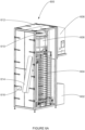
- FIG. 6A is a simplified illustration of a cold pack machine according to an example embodiment of the invention.
- Figure 6A shows a cold pack machine 600 with an optional insulated cabinet 612 with some panels open so as to provide a view inside the cold pack machine 600.
- the example embodiment cold pack machine 600 shown in Figure 6A includes:
- the cold pack machine 600 shown in Figure 6A optionally includes a dispensing chute 614.
- the cold pack machine 600 shown in Figure 6A optionally includes a control panel 616.
- FIG. 6B is a simplified illustration of a cold pack machine according to an example embodiment of the invention.
- Figure 6B shows a cold pack machine 630 without optional cabinet panels, so as to provide a view inside the cold pack machine 630.
- the example embodiment cold pack machine 630 shown in Figure 6B includes:
- the cold pack machine 600 shown in Figure 6B optionally includes a conveyor portion 634A, which conveys cold packs to a dispensing chute (not shown) such as, by way of a non-limiting example, the dispensing chute 614 of Figure 6A .
- the cold pack machine 600 shown in Figure 6B optionally includes a conveyor portion 633, which makes the conveyor 634, the conveyor portion 633 and optionally the conveyor 634A a closed loop conveyor or belt.
- the cold pack machine 600 optionally includes a refrigerant filler (not shown) such as the refrigerant filling component 602 of Figure 6A .
- the refrigerant filler optionally includes a device or conveyor which takes in a strip of SAM packs, which optionally conveys the strip of SAM packs past the refrigerant filler, optionally, by way of some non-limiting examples, such as the refrigerant filling devices shown in Figures 8A , 8B and 9 .
- FIG. 7 is a simplified block diagram illustration of a device for producing a SAM pack according to an example embodiment of the invention.
- Figure 7 shows a device 700 which includes:
- the pack forming component 702 and the filler component 704 are formed as one unit.
- FIG. 8A is a simplified illustration of a refrigerant filling and sealing machine according to an example embodiment of the invention.
- FIG. 8A shows a refrigerant filling and sealing machine 800, including:
- the refrigerant filling and sealing machine 800 includes an optional pressurization component for optionally pressurizing the refrigerant fluid for injection into SAM packs 814.
- the refrigerant filling and sealing machine 800 uses tap water as a refrigerant fluid, the tap water typically provided at a pressure of 1-4 bars.
- the pipe 805 enters a sleeve 812 of the SAM pack 814.
- the machine 800 includes a clamp 806 for clamping the sleeve 812 to the pipe 805 during an injecting of the refrigerant fluid.
- the machine 800 does not include a sealer 810.
- the machine 800 optionally does not seal all or some of the SAM packs 816 which have been injected with refrigerant fluid.
- Figure 8B is a simplified illustration of components of the refrigerant filling and sealing machine of Figure 8A .
- Figure 8B shows components of a refrigerant filling and sealing machine, including:
- cutting the edge open optionally slits open the sleeve 812 of the first SAM pack 814, opening the first SAM pack 814 to filling of refrigerant fluid through a side orifice in the refrigerant providing pipe 844.
- Figure 8B shows two open edges 834 of a second pack 816.
- Figure 8B shows the second pack 816 as a thicker pack than the SAM pack 814, to indicate that the second pack 816 has been filled with refrigerant fluid.
- a portion of an edge, or a whole edge, or a portion of more than one edge of the SAM pack 814 are sealed by adhesive, and the optional SAM pack edge separation device 832 does not necessarily include a knife 842 for cutting the edge 838 open.
- Figure 8C is a simplified illustration of an optional clamp and an optional piston or solenoid of the refrigerant filling and sealing machine of Figure 8A .
- Figure 8C shows one clamp 836 and one optional solenoid or piston 839.
- the clamp 836 optionally includes a half-hole 837 in the clamp 836 for allowing a water jet to pass through and optionally fill a SAM pack with water.
- the half-hole 837 potentially works together with another half-hole (not shown) in a mating clamp (not shown) to form a hole for allowing the water jet to pass through.
- the clamp 836 optionally seals the sleeve 812 of Figures 8A and 8B around the pipe 844 of Figures 8A and 8B during injection.
- the clamp 836 is optionally shaped with a recess 840B between two protuberances 840A 840C, so the protuberances 840A 840C clamp the sleeve 812 around the pipe 844, clamping the sleeve 812 so that refrigerant fluid does not leak and pressure is not lost between the sleeve 812 and the pipe 844.
- Figure 8D is a simplified illustration of a pipe for side fluid injection of the refrigerant filling and sealing machine of Figure 8A .
- Figure 8D shows the pipe 805 and the knife 842 of Figure 8B , and a side orifice 843 for injecting water into a SAM pack, such as the SAM pack 814 of Figure 8B .
- an end 849 of the pipe 805 is closed and rounded and/or shaped to work its way into the sleeve 812 of Figures 8A and 8B .
- Figure 8E is a simplified illustration of a SAM pack arranged for side fluid injection of the refrigerant filling and sealing machine of Figure 8A .
- Figure 8E shows a SAM pack 814, having a sleeve 812 along at least one side of the SAM pack 814.
- the pipe 805 of the refrigerant filling and sealing machine 800 of Figure 8A enters the sleeve 812 of the SAM pack 814
- the pipe 805 enters an opening 846 in the sleeve 812
- the optional knife 842 of Figure 8D optionally cuts a slit 847 in the sleeve 812, for the pipe 805 of Figure 8D to pass along the slit 847.
- Figure 8E shows an example embodiment of a SAM pack 814 which optionally includes a portion 848 of a seam of the SAM pack 814 designed for opening under fluid pressure and allowing refrigerant fluid into the SAM pack 814.
- portion 848 is glued, while a rest of the SAM pack 814 periphery is heat sealed.
- the portion 848 is lightly glued, to be waterproof but also openable under pressure as supplied by the pipe 805 of Figure 8A , while the rest of the periphery of the SAM pack 814 is optionally glued to remain sealed, and/or the rest of the periphery of the SAM pack 814 is optionally heat sealed.
- the pipe 805 provides tap water as a refrigerant fluid, the tap water typically provided at a pressure of 1-4 bars.
- the portion 848 is lightly heat sealed, by a thin seam, while a rest of the periphery of the SAM pack 814 is optionally better heat sealed, with a stronger and/or thicker seam.
- the portion 848 of the seam is sealed, whether glued or heat-sealed, so that a force of 50-500 grams pulling sides of the SAM pack 814 apart opens the portion of the seam.
- the portion 848 of the seam is sealed, whether glued or heat-sealed, so that a fluid refrigerant pressure in a range of 0.25-5 bars opens the portion 848 of the seam.
- using tap water at normal tap water pressure is sufficient to open the portion 848 of the seam.
- FIG. 8F is a simplified illustration of a SAM pack arranged for fluid injection of refrigerant fluid as an example useful for understanding the invention.
- Figure 8F shows a SAM pack 850, having a tubular opening 852 along one side of the SAM pack 850, and a tube 854 extending from the tubular opening 853 into the SAM pack 850.
- Figure 8F is a view of the SAM pack 850 with a partial cutout 856, in order to show the tube 854 even inside the SAM pack 850.
- the tube 854 is optionally mostly closed at an end distant from the opening 852, and optionally has one or more openings 858 at a portion of the tube 854 which is inside the SAM pack 850. In some embodiments the tube 854 optionally has a flat shape.
- Figure 8F shows a non-limiting example embodiment where the openings 858 are at corners of an internal end of the tube 854.
- the tube 854 optionally has a flat shape.
- the refrigerant fluid plus SAM mixture expands, exerting pressure on the tube 854 and mechanically sealing the tube 854, preventing leakage of the mixture.
- a refrigerant filling and sealing machine injects refrigerant fluid into the tube 854. Pressure of the refrigerant fluid is optionally sufficient to enable the refrigerant fluid to penetrate into the SAM pack 850, mix with the SAM inside, making a SAM and refrigerant fluid mixture. When enough refrigerant fluid has been injected, the SAM pack 850 is mechanically sealed by pressure of the mixture in the SAM pack 850, now a refrigerant pack.
- the refrigerant filling and sealing machine 800 of Figure 8A injects refrigerant fluid into the tube 854.
- a refrigerant fluid pressure in a range of 0.25-5 bars is sufficient to fill the SAM pack 850 with refrigerant fluid.
- using tap water at normal tap water pressure is sufficient to fill the SAM pack 850 with refrigerant fluid.
- FIGS 8G-L are simplified block diagram illustrations of a SAM pack fluid injection of refrigerant fluid according to an example embodiment of the invention.
- Figure 8G shows an example embodiment of a SAM pack 860.
- Figure 8H shows the SAM pack 860 cut along one edge, separated along a line 861 to form an open-edged SAM pack 860A, and a cutoff 860B.
- Figures 8I and 8J show two views from two perpendicular directions, of the sides of the open-edged SAM pack 860A being pulled open, optionally by vacuum arms or hoses 862A 862B. Figures 8I and 8J also show the open-edged SAM pack 860A being filled 864 with refrigerant fluid,
- Figure 8K shows the open-edged SAM pack 860A optionally being sealed 865A 865B along its open edge, producing a sealed refrigerant pack 860C.
- the sealing may be heat sealing or gluing, or other methods of sealing as described herein and/or as are known in the art.
- Figure 8L shows the sealed refrigerant pack 860C optionally placed or packaged side by side with additional sealed refrigerant packs 860C.
- the sealed refrigerant packs 860C are optionally placed 866 side by side by a vacuum arm or hose 862C.
- the vacuum arm or hose 862C is optionally one of the vacuum arms or hoses 862A 862B.
- the actions of opening, filling with refrigerant and sealing as described above with reference to Figures 8H-8K or 8H-8L are optionally performed by a specific machine suitable for this purpose.
- FIG. 9 is a simplified illustration of a refrigerant filling and sealing machine according to an example embodiment of the invention.
- Figure 9 shows a refrigerant filling and sealing machine 900, including:
- Figure 9 also shows a pack 924 which contains refrigerant fluid, and appears thicker than a SAM pack 920.
- the optional pressurization component 904 is a piston for providing pressure to the refrigerant fluid.
- the plunger 906 and needle 908 are optionally components of a syringe.
- the sealer 912 is a heat sealer, optionally solenoid operated or piston operated.
- the machine 900 uses tap water as a refrigerant fluid, the tap water typically provided at a pressure of 1-4 bars. In some embodiments the machine 900 uses tap water as a refrigerant fluid, and does not include a tank 902.
- Figure 10A is a simplified illustration of a SAM pack
- Figure 10B is a simplified illustration of a pack which has been injected with refrigerant fluid, according to an example embodiment of the invention.
- FIG. 10A shows a SAM pack 1040.
- the SAM pack 1040 may include all seams at the edges of the SAM pack 1040, or some seams, such as a top seam 1043, somewhat inward from an edge 1042 of the SAM pack 104.
- FIG. 10B shows a refrigerant pack 1045, which is the SAM pack 1040 after a hole 1044 has been made in the SAM pack 1040, refrigerant fluid has been injected into the pack, and the refrigerant fluid filled pack has optionally been sealed by a seam 1046 which seals off a section of the refrigerant pack 1045 which includes the hole 1044.
- the hole 1044 is made in a body of the SAM pack 1040, inward of the seam 1043. In some embodiments, where a seam of the SAM pack 1040 is at an edge of the SAM pack, the hole is inward of the edge 1042.
- the refrigerant pack 1045 is optionally sealed by the seam 1046 located between a body of the refrigerant pack 1045, containing all or most of the SAM and refrigerant fluid, and the hole 1044.
- Figure 10C is a simplified illustration of a SAM pack
- Figure 10D is a simplified illustration of a pack which has been injected with refrigerant fluid, according to an example embodiment of the invention.
- Figure 10C shows a SAM pack 1002, with a first seam 1004 for example at a bottom of the SAM pack 1002, and a second seam 1006, for example at a top of the SAM pack1002.
- the second seam 1006 optionally includes at least a portion 1008 of the seam 1006 in a crescent shape, for an injector to inject refrigerant fluid into the SAM pack 1002 in a vicinity of the crescent shaped portion 1008.
- Figure 10D shows a pack 1012 with the first seam 1004 and the second seam 1006, which is the SAM pack 1002 after a hole 1009 has been made in the SAM pack 1002, refrigerant fluid has been injected into the SAM pack 1002, and the refrigerant fluid filled pack has been sealed by a seam 1010 which seals off a section of the pack 1012 which includes the hole 1009.
- Figure 10E is a simplified illustration of a pack including a seam design according to an example embodiment of the invention.
- Figure 10E shows a pack 1020, with a bottom seam 1004 and a top seam 1021.
- the seam 1021 is optionally not sealed along a portion 1022 of the seam 1021, or sealed weakly, as defined elsewhere herein, along the portion 1022 of the seam 1021.
- the portion 1022 of the seam is sealed, whether glued or heat-sealed, so that a force of 50-500 grams pulling sides of the SAM pack 1020 apart opens the portion of the seam.
- the portion 1022 of the seam is sealed, whether glued or heat-sealed, so that a fluid refrigerant pressure in a range of 0.25-5 bars opens the portion 1020 of the seam.
- Refrigerant fluid is optionally injected through a location 1023 which is located above a line of the seam 1021, next to the not-sealed portion 1022 of the seam 1021. Following the injection, the pack 1020 is optionally sealed.
- the optional sealing is optionally performed along a line 1024.
- the line 1024 is crescent shaped, sealing the not-sealed portion 1022 of the seam 1021.
- the sealing is optionally performed at the not-sealed portion 1022 of the seam 1021, and/or along a straight line of the seam 1021, sealing the not-sealed portion 1022 of the seam 1021.
- the sealing is optionally performed both at the not-sealed portion 1022 of the seam 1021, and along the line 1024.
- Figure 10F is a simplified illustration of a pack including a seam design according to an example embodiment of the invention.
- Figure 10F shows a pack 1025, with a bottom seam 1004 and a top seam 1026.
- the seam 1026 is optionally not sealed, or weakly sealed, along a portion 1027, or even all, of the top seam 1026.
- Refrigerant fluid is optionally injected through a location 1028 which is located above a line of the seam 1026, next to the not-sealed or weakly sealed portion 1027 of the seam 1026. Following the injection, the pack 1025 is optionally sealed.
- the portion 1027 of the seam is sealed, whether glued or heat-sealed, so that a force of 50-500 grams pulling sides of the SAM pack 1025 apart opens the portion of the seam.
- the portion 1027 of the seam is sealed, whether glued or heat-sealed, so that a fluid refrigerant pressure in a range of 0.25-5 bars opens the portion 1027 of the seam.
- the sealing is optionally performed along a line of the seam 1026.
- the sealing is optionally performed only along the not-sealed portion 1027. In some embodiments the sealing is optionally performed along the entire seam 1026. In some embodiments the sealing is optionally along a line 1029 parallel to the seam 1026.
- Refrigerant fluid is optionally injected through a location 1028a which is located below a line of the seam 1026, and optionally sealed along a line 1029 parallel to the seam 1026.
- FIG. 10G is a simplified illustration of a pack including a seam design according to an example embodiment of the invention.
- Figure 10G shows a pack 1030, with a bottom seam 1004 and a top seam 1031.
- the pack contains SAM the seam 1031 is optionally not sealed along a portion 1032 of the seam 1031.
- Refrigerant fluid is optionally injected through a location 1033 which is located above a line of the seam 1031, next to the not-sealed portion 1032 of the seam 1031. Following the injection, the pack 1030 is optionally sealed.
- the sealing is optionally performed along a line 1034.
- the line 1034 is shaped to seal off the not-sealed portion 1032, by way of a non-limiting example by a rectangular-shaped seam 1034.
- the sealing is optionally performed at the not-sealed portion 1032 of the seam 1031, or along a straight line of the seam 1031, sealing the not-sealed portion 1032 of the seam 1031.
- sealing may be performed by heat sealing and/or by gluing.
- refrigerant fluid is added via a non-return valve.
- the absorbent material may be a Super Absorbent Material, SAP; or gelatin, or some other absorbent material.
- a preservative material such as, by way of some non-limiting examples a microorganism growth retardant material and/or potassium sorbate is added to the SAM.
- the refrigerant fluid may be water, de-salinated water, treated water, diethylene glycol, ethylene glycol, and/or a mixture thereof.
- Parameters for cold pack dispensing include, by way of some non-limiting examples:
- pack temperature is kept above a specific temperature, so as not to harm products with which the pack is placed.
- pack temperature is made as low as possible, to maintain cold for a longer time than higher temperatures.
- a pack size is selected to be large, to maintain cold for a longer time than a smaller pack.
- a number of packs to be used in packaging product(s) is selected to be more than one, optionally many more than one, to maintain cold for a longer time than one pack or a smaller number of packs.
- the packs optionally provide cooling action over a period of hours, and even days, for example 1 day, 2 days, 3 days, up to 7 days or even 14 days.
- a cold pack temperature of 4 degrees Celsius is selected, for use in packaging with some products, such as, by way of some non-limiting examples, pharmaceuticals and/or groceries which are to be kept cold but not frozen.
- a cold pack temperature of 0 degrees and frozen is selected, for use in packaging with some products. Such a cold pack will provide a cooling effect for a longer period of time than a cold pack at 0 degrees Celsius and not frozen.
- a cold pack temperature of -5 degrees Celsius is selected, for use in packaging with some products, such as, by way of a non-limiting example, some pharmaceuticals.
- a cold pack temperature of -18 degrees Celsius is selected, for use in packaging with some groceries. Such a temperature potentially reproduces temperature of some household freezers.
- a cold pack temperature of -30 degrees Celsius is selected, for use in packaging with some frozen products, by way of a non-limiting example such as meat.
- a cold pack temperature of -40 degrees Celsius is selected, for use in packaging with frozen products which may spend a long time in transit.
- pack temperature is kept above a specific temperature, so as not to harm products with which the pack is placed.
- pack temperature is made as low as possible, to maintain cold for a longer time than higher temperatures.
- a cold pack size is selected to be large, to maintain cold for a longer time than a smaller pack.
- a number or quantity of packs to be used in packaging product(s) is selected to be more than one, optionally many more than one, to maintain cold for a longer time than one pack or a smaller number of packs.
- goods packing parameters defining an optional cold pack request are translated to machine operation parameters or instructions.
- the cold pack request is translated, via a look-up table, to a number and/or temperature and/or size of cold packs and/or other cold pack parameters as described herein.
- the look-up table optionally includes one or more input parameters such as, by way of some non-limiting examples, weight, volume, type of goods, insulation properties of a packing box and/or type of box, expected time of goods staying in the box during shipment to destination.
- the look-up table optionally includes one or more output parameters such as, by way of some non-limiting examples, temperature, size of cold pack, number of cold packs, cooling blower operating intensity or setting.
- the cold pack request is translated, via a look-up table, to a number and/or temperature and/or size of cold packs and/or other cold pack parameters as described herein.
- the cold pack request is translated, by calculation, to a number and/or temperature and/or size of cold packs and/or other cold pack parameters as described herein.
- the calculation may be based on estimated heat retention and/or dissipation properties of the goods in a box and of the box.
- a cold pack machine is optionally empty of cold packs when a request for cold packs at a specific temperature arrives. In some embodiments, the cold pack machine manufactures a number of cold packs per the request, at the temperature requested.
- a cold pack machine optionally already contains cold packs at a first temperature when a request for additional cold packs at the first specific temperature arrives, and the cold pack machine dispenses a requested number of cold packs at the first requested temperature.
- a cold pack machine optionally already contains cold packs at a first temperature when a request for additional cold packs at a second, warmer temperature arrives.
- the cold pack machine optionally warms the requested number of cold packs to the requested second temperature and optionally dispenses the requested number of cold packs at the second requested temperature.
- the warming is by blowing warm air instead of cold air through a cold pack refrigerating section of the cold pack machine, optionally controlling the desired temperature and halting the warming when the second temperature is reached.
- a cold pack machine optionally already contains cold packs at a first temperature when a request for additional cold packs at a second, colder temperature arrives.
- the cold pack machine optionally refrigerates the requested number of cold packs to the requested second temperature and optionally dispenses the requested number of cold packs at the second requested temperature.
- the refrigeration is by blowing more cold air, and/or colder air, through a cold pack refrigerating section of the cold pack machine, optionally controlling the desired temperature and halting the refrigeration when the second temperature is reached.
- absorbent material and SAM are intended to include all such new technologies a priori.
- refrigerant fluid is intended to include all such new technologies a priori.
- compositions, method or structure may include additional ingredients, steps and/or parts, but only if the additional ingredients, steps and/or parts do not materially alter the basic and novel characteristics of the claimed composition, method or structure.
- a unit or “at least one unit” may include a plurality of units, including combinations thereof.
- range format is merely for convenience and brevity and should not be construed as an inflexible limitation on the scope of the invention. Accordingly, the description of a range should be considered to have specifically disclosed all the possible sub-ranges as well as individual numerical values within that range. For example, description of a range such as from 1 to 6 should be considered to have specifically disclosed sub-ranges such as from 1 to 3, from 1 to 4, from 1 to 5, from 2 to 4, from 2 to 6, from 3 to 6 etc., as well as individual numbers within that range, for example, 1, 2, 3, 4, 5, and 6. This applies regardless of the breadth of the range.
Landscapes
- Engineering & Computer Science (AREA)
- Physics & Mathematics (AREA)
- Thermal Sciences (AREA)
- Health & Medical Sciences (AREA)
- Animal Behavior & Ethology (AREA)
- Heart & Thoracic Surgery (AREA)
- Vascular Medicine (AREA)
- Life Sciences & Earth Sciences (AREA)
- Biomedical Technology (AREA)
- General Health & Medical Sciences (AREA)
- Public Health (AREA)
- Veterinary Medicine (AREA)
- Chemical & Material Sciences (AREA)
- Combustion & Propulsion (AREA)
- Mechanical Engineering (AREA)
- General Engineering & Computer Science (AREA)
- Packages (AREA)
Claims (9)
- Ein System (280) zur Abgabe eines Kühlmittelpakets, umfassend:eine Fülleinheit (284) zum Einfüllen von Kühlmittelfluid in das Innere eines Pakets aus superabsorbierendem Material (SAM), wodurch ein Kühlmittelpaket hergestellt wird;gekennzeichnet durch:die Fülleinheit (284), die so konfiguriert ist, dass sie das Kühlmittelfluid in das Innere eines versiegelten Pakets aus superabsorbierendem Material (SAM) einspritzt, das zuvor kein Kühlmittelfluid enthielt;das System umfasst eine Spritze (908) zum:Durchstechen der Packung aus superabsorbierendem Material (SAM); undEinspritzen des Kühlmittelfluids in das Innere der Packung aus superabsorbierendem Material (SAM),wodurch ein Kühlmittelpaket hergestellt wird.
- Das System nach Anspruch 1, weiterhin umfassend eine Dichtungseinheit (286) zum erneuten Abdichten des Kältemittelpakets.
- Das System gemäß einem der Ansprüche 1-2, weiterhin umfassend eine erste Kühleinheit zum Kühlen des Kühlmittelpakets, wodurch ein Kühlpack erzeugt wird.
- Ein Verfahren zur Bereitstellung eines Kühlmittelpakets, umfassend:Bereitstellen eines versiegelten Beutels (110) mit superabsorbierendem Material (SAM) im Inneren und ohne Kühlmittelfluid im Inneren;Hinzufügen von Kühlmittelfluid in ein Inneres des versiegelten Beutels (110) durch:Verwenden einer Spritze (908), um den versiegelten Beutel (110) zu durchstechen und das Kühlmittelfluid in das Innere des Beutels (110) zu injizieren; oderAufschneiden den versiegelten Beutel (110) entlang einer Kante und Füllen des Kühlmittelfluids in das Innere des Beutels,wodurch ein Kühlmittelpaket entsteht; undWiederversiegeln des Kühlmittelpakets.
- Das Verfahren nach Anspruch 4, wobei das Bereitstellen des versiegelten Beutels das Bereitstellen einer Vielzahl von versiegelten Beuteln (110) als ein zusammenhängender Streifen von versiegelten Beuteln mit superabsorbierendem Material (SAM) im Inneren und ohne Kühlmittelfluid im Inneren umfasst.
- Das Verfahren nach Anspruch 4, wobei das Bereitstellen des versiegelten Beutels das Bereitstellen einer Vielzahl von versiegelten Beuteln als ein fächerförmig gefalteter, zusammenhängender Streifen von versiegelten Beuteln mit superabsorbierendem Material (SAM) im Inneren und ohne Kühlmittelfluid im Inneren umfasst.
- Das Verfahren nach einem der Ansprüche 4-6, weiterhin umfassend Kühlen des Kühlmittelpakets, wodurch eine Kühlpack hergestellt wird.
- Das Verfahren nach einem der Ansprüche 4- 7, weiterhin umfassend Einfrieren des Kühlmittelpakets, wodurch ein Gefrierpack hergestellt wird.
- Das Verfahren nach einem der Ansprüche 4- 8, weiterhin umfassend:Empfangen einer elektronischen Anforderung zur Abgabe einer bestimmten Anzahl von Kühlpacks bei einer bestimmten Temperatur; undBereitstellen der bestimmten Anzahl von Kühlpacks bei der bestimmten Temperatur.
Applications Claiming Priority (2)
| Application Number | Priority Date | Filing Date | Title |
|---|---|---|---|
| US201762549470P | 2017-08-24 | 2017-08-24 | |
| PCT/IL2018/050931 WO2019038767A1 (en) | 2017-08-24 | 2018-08-23 | REFRIGERANT PACK SYSTEM |
Publications (3)
| Publication Number | Publication Date |
|---|---|
| EP3672539A1 EP3672539A1 (de) | 2020-07-01 |
| EP3672539A4 EP3672539A4 (de) | 2021-05-19 |
| EP3672539B1 true EP3672539B1 (de) | 2025-05-07 |
Family
ID=65438486
Family Applications (1)
| Application Number | Title | Priority Date | Filing Date |
|---|---|---|---|
| EP18847522.2A Active EP3672539B1 (de) | 2017-08-24 | 2018-08-23 | Kühlakkusystem |
Country Status (5)
| Country | Link |
|---|---|
| US (1) | US12584675B2 (de) |
| EP (1) | EP3672539B1 (de) |
| AU (1) | AU2018320726A1 (de) |
| CA (1) | CA3072611A1 (de) |
| WO (1) | WO2019038767A1 (de) |
Families Citing this family (6)
| Publication number | Priority date | Publication date | Assignee | Title |
|---|---|---|---|---|
| CA3072611A1 (en) | 2017-08-24 | 2019-02-28 | Arctic Express Packs LLC | Cold packs system |
| WO2020198863A1 (en) * | 2019-04-01 | 2020-10-08 | Einhorn Mordechai | System and methods for providing cooling to an interior of a container |
| US20210207015A1 (en) * | 2020-01-06 | 2021-07-08 | Mordechai Einhorn | Refrigeration pack product and method for providing same comprising providing a slurry including a thickening agent |
| US20230190521A1 (en) * | 2020-04-28 | 2023-06-22 | Arctic Express Packs LLC | Dispensing cold packs |
| US11140797B1 (en) * | 2020-07-31 | 2021-10-05 | Tamara Phipps | Apparatus for enhancing cooling of an electronic computing device and method of use |
| US12147933B2 (en) * | 2021-06-03 | 2024-11-19 | Hungryroot, Inc. | Automated packaging assembly line for perishable items |
Citations (2)
| Publication number | Priority date | Publication date | Assignee | Title |
|---|---|---|---|---|
| GB2251206A (en) * | 1990-12-28 | 1992-07-01 | Sorba Freeze Limited | Packaging system |
| US20060173430A1 (en) * | 2005-02-03 | 2006-08-03 | Baosheng Lee | Fluid-absorbing products comprising superabsorbent material in a water-soluble pouch and methods of using the same |
Family Cites Families (29)
| Publication number | Priority date | Publication date | Assignee | Title |
|---|---|---|---|---|
| DE1914942A1 (de) | 1968-04-01 | 1969-11-06 | Skogsaegarnas Ind Aktiebolag | Verfahren zum Verschliessen der Ventiloeffnungen von Ventilsaecken mittels eines Klebstoffes und Vorrichtung zur Ausfuehrung des Verfahrens |
| US3951127A (en) | 1973-06-28 | 1976-04-20 | Kay Laboratories, Inc. | Constant temperature device |
| US4856651A (en) * | 1987-12-22 | 1989-08-15 | Francis Jr Sam E | Chemical thermal pack and method of making same |
| SE463747B (sv) * | 1989-05-31 | 1991-01-21 | Moelnlycke Ab | Absorberande alster innefattande aatminstone tvaa olika superabsorbenter |
| US5150707A (en) * | 1990-06-18 | 1992-09-29 | Medico International, Inc. | Absorbent assembly for use as a thermal pack |
| US6376034B1 (en) * | 1996-01-23 | 2002-04-23 | William M. Brander | Absorbent material for use in disposable articles and articles prepared therefrom |
| US5709089A (en) | 1996-03-04 | 1998-01-20 | Dawson; Gregory D. | Package for cooling containing superabsorbent polymer |
| US6478147B1 (en) | 1998-03-27 | 2002-11-12 | William M. Brander | Container with absorbent material |
| US6058735A (en) * | 1998-05-05 | 2000-05-09 | Nathan; William F. | Printed cold pack |
| US6491993B1 (en) * | 1999-08-12 | 2002-12-10 | Pactiv Corporation | Absorbent pouches |
| US20030139291A1 (en) | 2001-12-04 | 2003-07-24 | Kimberly-Clark Worldwide, Inc. | Absorbent composites having cooling effect |
| MXPA05008214A (es) | 2003-02-14 | 2005-10-05 | Kimberly Clark Co | Envase con caracteristica de abertura facil. |
| US7169843B2 (en) | 2003-04-25 | 2007-01-30 | Stockhausen, Inc. | Superabsorbent polymer with high permeability |
| KR20070020853A (ko) * | 2005-08-17 | 2007-02-22 | 주식회사 팜텍 | 찜질팩에 냉매나 열매를 주입하는 방법 |
| DK176304B1 (da) | 2005-08-30 | 2007-07-09 | Jens Harder Hoejbjerg | Varmepude |
| US8829107B2 (en) | 2006-02-28 | 2014-09-09 | Evonik Degussa Gmbh | Biodegradable superabsorbent polymer composition with good absorption and retention properties |
| WO2008021212A2 (en) * | 2006-08-11 | 2008-02-21 | Payload Systems, Inc. | High speed swelling, pressure exerting hemostatic device |
| US20090120824A1 (en) | 2007-09-18 | 2009-05-14 | John Piazza | Diaper package with plurality of individual diaper packages vacuum packed therein |
| US9681832B2 (en) * | 2008-04-11 | 2017-06-20 | Glucovista Inc. | Measurement apparatuses and methods using a combined substance cooling device |
| WO2010055514A2 (en) | 2008-11-13 | 2010-05-20 | Polynest Technologies Ltd. | Apparatus and method for packaging |
| US20110126582A1 (en) | 2009-05-28 | 2011-06-02 | Coldpack, Inc. | Method and system for fillable gel pack |
| US10875274B2 (en) | 2011-11-29 | 2020-12-29 | Columbia Sportswear North America, Inc. | Cooling material |
| BR112018002061B1 (pt) | 2015-07-31 | 2023-03-21 | The Procter & Gamble Company | Substrato não-tecido de filamentos contínuos termossoldados |
| WO2018132812A1 (en) | 2017-01-16 | 2018-07-19 | Domtar Paper Company, Llc | Disposable ice pack |
| CA3072611A1 (en) | 2017-08-24 | 2019-02-28 | Arctic Express Packs LLC | Cold packs system |
| WO2019195272A1 (en) | 2018-04-02 | 2019-10-10 | Green Polymers Ltd. | Process for the production of biodegradable superabsorbent polymer with high absorbency under load based on styrene maleic acid copolymers and biopolymer |
| US12059877B2 (en) | 2018-06-19 | 2024-08-13 | Board Of Trustees Of Western Michigan University | Expandable and/or disposable ice pack |
| US20230190521A1 (en) | 2020-04-28 | 2023-06-22 | Arctic Express Packs LLC | Dispensing cold packs |
| KR102932122B1 (ko) | 2020-05-19 | 2026-02-26 | 텔레폰악티에볼라겟엘엠에릭슨(펍) | 주파수 대역 선택 및 측정 구성의 관리 |
-
2018
- 2018-08-23 CA CA3072611A patent/CA3072611A1/en active Pending
- 2018-08-23 AU AU2018320726A patent/AU2018320726A1/en not_active Abandoned
- 2018-08-23 WO PCT/IL2018/050931 patent/WO2019038767A1/en not_active Ceased
- 2018-08-23 EP EP18847522.2A patent/EP3672539B1/de active Active
- 2018-08-23 US US16/641,277 patent/US12584675B2/en active Active
Patent Citations (2)
| Publication number | Priority date | Publication date | Assignee | Title |
|---|---|---|---|---|
| GB2251206A (en) * | 1990-12-28 | 1992-07-01 | Sorba Freeze Limited | Packaging system |
| US20060173430A1 (en) * | 2005-02-03 | 2006-08-03 | Baosheng Lee | Fluid-absorbing products comprising superabsorbent material in a water-soluble pouch and methods of using the same |
Also Published As
| Publication number | Publication date |
|---|---|
| EP3672539A4 (de) | 2021-05-19 |
| WO2019038767A1 (en) | 2019-02-28 |
| US12584675B2 (en) | 2026-03-24 |
| AU2018320726A1 (en) | 2020-03-12 |
| EP3672539A1 (de) | 2020-07-01 |
| US20200182526A1 (en) | 2020-06-11 |
| CA3072611A1 (en) | 2019-02-28 |
Similar Documents
| Publication | Publication Date | Title |
|---|---|---|
| EP3672539B1 (de) | Kühlakkusystem | |
| WO2010132726A1 (en) | Thermal containment system providing temperature maintaining shipping package with segmented flexible pcm panels | |
| US8600903B2 (en) | Containers for transferring products and methods for their transfer | |
| CA2779327C (en) | Method and system for temperature controlled transport | |
| US9689601B2 (en) | Bag sealer and ice vending machine using the same | |
| US20230190521A1 (en) | Dispensing cold packs | |
| JP2008516872A (ja) | 生鮮食品の加工と流通のための装置および方法 | |
| EP3173715A1 (de) | Verfahren und vorrichtung zur zuweisung einer kühlsubstanz | |
| US5966962A (en) | Modular hydration and freezing plant for flexible refrigerant media | |
| USRE34533E (en) | Method for preparing ice for transportation | |
| US3096626A (en) | Method of chilling, storing and shipping perishable materials | |
| US10690405B2 (en) | Methods and apparatus for freezing a liquid | |
| CN110268209B (zh) | 物流系统以及物流方法 | |
| US20200399003A1 (en) | Method and apparatus for automatically packaging and dispensing food products | |
| KR20180096048A (ko) | 아이스팩 제조장치 및 그 제조방법 | |
| US20170061725A1 (en) | Frozen Freezer Pack | |
| CN203497413U (zh) | 蓄冷式软冰排 | |
| CN207258051U (zh) | 一种食物保鲜集装箱 | |
| KR102819819B1 (ko) | 신선제품용 보냉 포장팩 | |
| KR20010021754A (ko) | 가요성 냉동 매체용 수성 및 결빙 플랜트 | |
| US10842160B2 (en) | Method and apparatus for automatically packaging and dispensing food products | |
| CN121536129A (zh) | 冷藏货厢的控制方法和冷藏货厢 | |
| AU2013100712A4 (en) | Temperature control device | |
| RU2566893C2 (ru) | Линия упаковки продукции на поддонах | |
| KR20260025308A (ko) | 제어 커맨드를 저장 및/또는 준비하기 위한 방법 |
Legal Events
| Date | Code | Title | Description |
|---|---|---|---|
| STAA | Information on the status of an ep patent application or granted ep patent |
Free format text: STATUS: THE INTERNATIONAL PUBLICATION HAS BEEN MADE |
|
| PUAI | Public reference made under article 153(3) epc to a published international application that has entered the european phase |
Free format text: ORIGINAL CODE: 0009012 |
|
| STAA | Information on the status of an ep patent application or granted ep patent |
Free format text: STATUS: REQUEST FOR EXAMINATION WAS MADE |
|
| 17P | Request for examination filed |
Effective date: 20200317 |
|
| AK | Designated contracting states |
Kind code of ref document: A1 Designated state(s): AL AT BE BG CH CY CZ DE DK EE ES FI FR GB GR HR HU IE IS IT LI LT LU LV MC MK MT NL NO PL PT RO RS SE SI SK SM TR |
|
| AX | Request for extension of the european patent |
Extension state: BA ME |
|
| DAV | Request for validation of the european patent (deleted) | ||
| DAX | Request for extension of the european patent (deleted) | ||
| A4 | Supplementary search report drawn up and despatched |
Effective date: 20210416 |
|
| RIC1 | Information provided on ipc code assigned before grant |
Ipc: A61F 7/02 20060101AFI20210412BHEP Ipc: A61F 7/10 20060101ALI20210412BHEP Ipc: F25D 5/02 20060101ALI20210412BHEP Ipc: F25D 3/08 20060101ALI20210412BHEP |
|
| STAA | Information on the status of an ep patent application or granted ep patent |
Free format text: STATUS: EXAMINATION IS IN PROGRESS |
|
| 17Q | First examination report despatched |
Effective date: 20230103 |
|
| GRAP | Despatch of communication of intention to grant a patent |
Free format text: ORIGINAL CODE: EPIDOSNIGR1 |
|
| STAA | Information on the status of an ep patent application or granted ep patent |
Free format text: STATUS: GRANT OF PATENT IS INTENDED |
|
| INTG | Intention to grant announced |
Effective date: 20241209 |
|
| RIN1 | Information on inventor provided before grant (corrected) |
Inventor name: BUNNETT, BRIAN H. Inventor name: NEVO, SHLOMO |
|
| GRAS | Grant fee paid |
Free format text: ORIGINAL CODE: EPIDOSNIGR3 |
|
| GRAA | (expected) grant |
Free format text: ORIGINAL CODE: 0009210 |
|
| STAA | Information on the status of an ep patent application or granted ep patent |
Free format text: STATUS: THE PATENT HAS BEEN GRANTED |
|
| AK | Designated contracting states |
Kind code of ref document: B1 Designated state(s): AL AT BE BG CH CY CZ DE DK EE ES FI FR GB GR HR HU IE IS IT LI LT LU LV MC MK MT NL NO PL PT RO RS SE SI SK SM TR |
|
| REG | Reference to a national code |
Ref country code: GB Ref legal event code: FG4D |
|
| REG | Reference to a national code |
Ref country code: CH Ref legal event code: EP |
|
| REG | Reference to a national code |
Ref country code: DE Ref legal event code: R096 Ref document number: 602018081789 Country of ref document: DE |
|
| REG | Reference to a national code |
Ref country code: IE Ref legal event code: FG4D |
|
| REG | Reference to a national code |
Ref country code: NL Ref legal event code: MP Effective date: 20250507 |
|
| PG25 | Lapsed in a contracting state [announced via postgrant information from national office to epo] |
Ref country code: ES Free format text: LAPSE BECAUSE OF FAILURE TO SUBMIT A TRANSLATION OF THE DESCRIPTION OR TO PAY THE FEE WITHIN THE PRESCRIBED TIME-LIMIT Effective date: 20250507 Ref country code: FI Free format text: LAPSE BECAUSE OF FAILURE TO SUBMIT A TRANSLATION OF THE DESCRIPTION OR TO PAY THE FEE WITHIN THE PRESCRIBED TIME-LIMIT Effective date: 20250507 Ref country code: PT Free format text: LAPSE BECAUSE OF FAILURE TO SUBMIT A TRANSLATION OF THE DESCRIPTION OR TO PAY THE FEE WITHIN THE PRESCRIBED TIME-LIMIT Effective date: 20250908 |
|
| PGFP | Annual fee paid to national office [announced via postgrant information from national office to epo] |
Ref country code: DE Payment date: 20250820 Year of fee payment: 8 |
|
| REG | Reference to a national code |
Ref country code: LT Ref legal event code: MG9D |
|
| PG25 | Lapsed in a contracting state [announced via postgrant information from national office to epo] |
Ref country code: NO Free format text: LAPSE BECAUSE OF FAILURE TO SUBMIT A TRANSLATION OF THE DESCRIPTION OR TO PAY THE FEE WITHIN THE PRESCRIBED TIME-LIMIT Effective date: 20250807 Ref country code: GR Free format text: LAPSE BECAUSE OF FAILURE TO SUBMIT A TRANSLATION OF THE DESCRIPTION OR TO PAY THE FEE WITHIN THE PRESCRIBED TIME-LIMIT Effective date: 20250808 |
|
| PG25 | Lapsed in a contracting state [announced via postgrant information from national office to epo] |
Ref country code: NL Free format text: LAPSE BECAUSE OF FAILURE TO SUBMIT A TRANSLATION OF THE DESCRIPTION OR TO PAY THE FEE WITHIN THE PRESCRIBED TIME-LIMIT Effective date: 20250507 Ref country code: PL Free format text: LAPSE BECAUSE OF FAILURE TO SUBMIT A TRANSLATION OF THE DESCRIPTION OR TO PAY THE FEE WITHIN THE PRESCRIBED TIME-LIMIT Effective date: 20250507 |
|
| REG | Reference to a national code |
Ref country code: AT Ref legal event code: MK05 Ref document number: 1791659 Country of ref document: AT Kind code of ref document: T Effective date: 20250507 |
|
| PG25 | Lapsed in a contracting state [announced via postgrant information from national office to epo] |
Ref country code: BG Free format text: LAPSE BECAUSE OF FAILURE TO SUBMIT A TRANSLATION OF THE DESCRIPTION OR TO PAY THE FEE WITHIN THE PRESCRIBED TIME-LIMIT Effective date: 20250507 |
|
| PGFP | Annual fee paid to national office [announced via postgrant information from national office to epo] |
Ref country code: GB Payment date: 20250820 Year of fee payment: 8 |
|
| PG25 | Lapsed in a contracting state [announced via postgrant information from national office to epo] |
Ref country code: HR Free format text: LAPSE BECAUSE OF FAILURE TO SUBMIT A TRANSLATION OF THE DESCRIPTION OR TO PAY THE FEE WITHIN THE PRESCRIBED TIME-LIMIT Effective date: 20250507 |
|
| PG25 | Lapsed in a contracting state [announced via postgrant information from national office to epo] |
Ref country code: AT Free format text: LAPSE BECAUSE OF FAILURE TO SUBMIT A TRANSLATION OF THE DESCRIPTION OR TO PAY THE FEE WITHIN THE PRESCRIBED TIME-LIMIT Effective date: 20250507 |
|
| PGFP | Annual fee paid to national office [announced via postgrant information from national office to epo] |
Ref country code: FR Payment date: 20250828 Year of fee payment: 8 |
|
| PG25 | Lapsed in a contracting state [announced via postgrant information from national office to epo] |
Ref country code: RS Free format text: LAPSE BECAUSE OF FAILURE TO SUBMIT A TRANSLATION OF THE DESCRIPTION OR TO PAY THE FEE WITHIN THE PRESCRIBED TIME-LIMIT Effective date: 20250807 |
|
| PG25 | Lapsed in a contracting state [announced via postgrant information from national office to epo] |
Ref country code: IS Free format text: LAPSE BECAUSE OF FAILURE TO SUBMIT A TRANSLATION OF THE DESCRIPTION OR TO PAY THE FEE WITHIN THE PRESCRIBED TIME-LIMIT Effective date: 20250907 |
|
| PG25 | Lapsed in a contracting state [announced via postgrant information from national office to epo] |
Ref country code: LV Free format text: LAPSE BECAUSE OF FAILURE TO SUBMIT A TRANSLATION OF THE DESCRIPTION OR TO PAY THE FEE WITHIN THE PRESCRIBED TIME-LIMIT Effective date: 20250507 |
|
| PG25 | Lapsed in a contracting state [announced via postgrant information from national office to epo] |
Ref country code: DK Free format text: LAPSE BECAUSE OF FAILURE TO SUBMIT A TRANSLATION OF THE DESCRIPTION OR TO PAY THE FEE WITHIN THE PRESCRIBED TIME-LIMIT Effective date: 20250507 Ref country code: SM Free format text: LAPSE BECAUSE OF FAILURE TO SUBMIT A TRANSLATION OF THE DESCRIPTION OR TO PAY THE FEE WITHIN THE PRESCRIBED TIME-LIMIT Effective date: 20250507 |
|
| PG25 | Lapsed in a contracting state [announced via postgrant information from national office to epo] |
Ref country code: CZ Free format text: LAPSE BECAUSE OF FAILURE TO SUBMIT A TRANSLATION OF THE DESCRIPTION OR TO PAY THE FEE WITHIN THE PRESCRIBED TIME-LIMIT Effective date: 20250507 |
|
| PG25 | Lapsed in a contracting state [announced via postgrant information from national office to epo] |
Ref country code: EE Free format text: LAPSE BECAUSE OF FAILURE TO SUBMIT A TRANSLATION OF THE DESCRIPTION OR TO PAY THE FEE WITHIN THE PRESCRIBED TIME-LIMIT Effective date: 20250507 |
|
| PG25 | Lapsed in a contracting state [announced via postgrant information from national office to epo] |
Ref country code: RO Free format text: LAPSE BECAUSE OF FAILURE TO SUBMIT A TRANSLATION OF THE DESCRIPTION OR TO PAY THE FEE WITHIN THE PRESCRIBED TIME-LIMIT Effective date: 20250507 Ref country code: SK Free format text: LAPSE BECAUSE OF FAILURE TO SUBMIT A TRANSLATION OF THE DESCRIPTION OR TO PAY THE FEE WITHIN THE PRESCRIBED TIME-LIMIT Effective date: 20250507 |
|
| PG25 | Lapsed in a contracting state [announced via postgrant information from national office to epo] |
Ref country code: IT Free format text: LAPSE BECAUSE OF FAILURE TO SUBMIT A TRANSLATION OF THE DESCRIPTION OR TO PAY THE FEE WITHIN THE PRESCRIBED TIME-LIMIT Effective date: 20250507 |
|
| REG | Reference to a national code |
Ref country code: DE Ref legal event code: R097 Ref document number: 602018081789 Country of ref document: DE |
|
| PLBE | No opposition filed within time limit |
Free format text: ORIGINAL CODE: 0009261 |
|
| STAA | Information on the status of an ep patent application or granted ep patent |
Free format text: STATUS: NO OPPOSITION FILED WITHIN TIME LIMIT |
|
| REG | Reference to a national code |
Ref country code: CH Ref legal event code: L10 Free format text: ST27 STATUS EVENT CODE: U-0-0-L10-L00 (AS PROVIDED BY THE NATIONAL OFFICE) Effective date: 20260318 |
|
| REG | Reference to a national code |
Ref country code: CH Ref legal event code: H13 Free format text: ST27 STATUS EVENT CODE: U-0-0-H10-H13 (AS PROVIDED BY THE NATIONAL OFFICE) Effective date: 20260324 |
|
| PG25 | Lapsed in a contracting state [announced via postgrant information from national office to epo] |
Ref country code: MC Free format text: LAPSE BECAUSE OF FAILURE TO SUBMIT A TRANSLATION OF THE DESCRIPTION OR TO PAY THE FEE WITHIN THE PRESCRIBED TIME-LIMIT Effective date: 20250507 |
|
| 26N | No opposition filed |
Effective date: 20260210 |
|
| PG25 | Lapsed in a contracting state [announced via postgrant information from national office to epo] |
Ref country code: LU Free format text: LAPSE BECAUSE OF NON-PAYMENT OF DUE FEES Effective date: 20250823 |
|
| PG25 | Lapsed in a contracting state [announced via postgrant information from national office to epo] |
Ref country code: CH Free format text: LAPSE BECAUSE OF NON-PAYMENT OF DUE FEES Effective date: 20250831 |