EP3672381B1 - Zusammenbauverfahren eines elektrischen geräts, insbesondere eines wechselrichters - Google Patents
Zusammenbauverfahren eines elektrischen geräts, insbesondere eines wechselrichters Download PDFInfo
- Publication number
- EP3672381B1 EP3672381B1 EP19213491.4A EP19213491A EP3672381B1 EP 3672381 B1 EP3672381 B1 EP 3672381B1 EP 19213491 A EP19213491 A EP 19213491A EP 3672381 B1 EP3672381 B1 EP 3672381B1
- Authority
- EP
- European Patent Office
- Prior art keywords
- subassembly
- support
- electrical equipment
- face
- electrical
- Prior art date
- Legal status (The legal status is an assumption and is not a legal conclusion. Google has not performed a legal analysis and makes no representation as to the accuracy of the status listed.)
- Active
Links
Images

Classifications
-
- H—ELECTRICITY
- H02—GENERATION; CONVERSION OR DISTRIBUTION OF ELECTRIC POWER
- H02M—APPARATUS FOR CONVERSION BETWEEN AC AND AC, BETWEEN AC AND DC, OR BETWEEN DC AND DC, AND FOR USE WITH MAINS OR SIMILAR POWER SUPPLY SYSTEMS; CONVERSION OF DC OR AC INPUT POWER INTO SURGE OUTPUT POWER; CONTROL OR REGULATION THEREOF
- H02M7/00—Conversion of AC power input into DC power output; Conversion of DC power input into AC power output
- H02M7/003—Constructional details, e.g. physical layout, assembly, wiring or busbar connections
-
- H—ELECTRICITY
- H05—ELECTRIC TECHNIQUES NOT OTHERWISE PROVIDED FOR
- H05K—PRINTED CIRCUITS; CASINGS OR CONSTRUCTIONAL DETAILS OF ELECTRIC APPARATUS; MANUFACTURE OF ASSEMBLAGES OF ELECTRICAL COMPONENTS
- H05K7/00—Constructional details common to different types of electric apparatus
- H05K7/14—Mounting supporting structure in casing or on frame or rack
- H05K7/1422—Printed circuit boards receptacles, e.g. stacked structures, electronic circuit modules or box like frames
- H05K7/1427—Housings
- H05K7/1432—Housings specially adapted for power drive units or power converters
- H05K7/14329—Housings specially adapted for power drive units or power converters specially adapted for the configuration of power bus bars
-
- H—ELECTRICITY
- H02—GENERATION; CONVERSION OR DISTRIBUTION OF ELECTRIC POWER
- H02M—APPARATUS FOR CONVERSION BETWEEN AC AND AC, BETWEEN AC AND DC, OR BETWEEN DC AND DC, AND FOR USE WITH MAINS OR SIMILAR POWER SUPPLY SYSTEMS; CONVERSION OF DC OR AC INPUT POWER INTO SURGE OUTPUT POWER; CONTROL OR REGULATION THEREOF
- H02M1/00—Details of apparatus for conversion
- H02M1/12—Arrangements for reducing harmonics from AC input or output
-
- H—ELECTRICITY
- H02—GENERATION; CONVERSION OR DISTRIBUTION OF ELECTRIC POWER
- H02M—APPARATUS FOR CONVERSION BETWEEN AC AND AC, BETWEEN AC AND DC, OR BETWEEN DC AND DC, AND FOR USE WITH MAINS OR SIMILAR POWER SUPPLY SYSTEMS; CONVERSION OF DC OR AC INPUT POWER INTO SURGE OUTPUT POWER; CONTROL OR REGULATION THEREOF
- H02M1/00—Details of apparatus for conversion
- H02M1/44—Circuits or arrangements for compensating for electromagnetic interference in converters or inverters
Definitions
- the present invention relates to the field of electrical equipment, particularly high voltage.
- the present invention aims more particularly at the assembly of such electrical equipment, in particular inverters.
- a filtering device of the “DC-link capacitor” type has the particular function of stabilizing the voltage supplied to the active device.
- the support plate also called “bracket”, provides in particular a protection function against electromagnetic disturbances, in other words an electromagnetic shielding function.
- the support plate thus contributes to the electromagnetic compatibility of the electrical equipment (commonly referred to in French by the acronym CEM).
- Electromagnetic compatibility aims to ensure on the one hand that the electrical equipment is able to operate itself without disturbances, in its electromagnetic environment, and on the other hand that it is also able to operate without introducing electromagnetic disturbances likely to harm the proper functioning of third-party electrical equipment located nearby.
- the electrical equipment can be arranged together in a single housing within an electrical system.
- the housings of the two electrical equipment are thus merged, which improves integration into the vehicle.
- an electrical system comprises first electrical equipment, such as an inverter, and second electrical equipment, such as than an electric motor, housed in a single housing.
- the housing then includes a respective housing for each electrical equipment.
- the bulk of such a box complicates the operation of assembling electrical equipment, because it is more bulky than the usual boxes of electrical equipment taken in isolation.
- the components of the electrical equipment are mounted on the cover of the electrical equipment housing. Thanks to the electrical assembly according to the invention, the components of the electrical equipment can therefore be first arranged together, then mounted all at once in a housing of the electrical equipment. Thus, it is not necessary to adapt the assembly line of the electrical components of the electrical equipment to the size of the housing of said electrical equipment.
- the invention is particularly advantageous when the housing comprises two pieces of electrical equipment, as is the case in an electrical system described previously.
- the invention will be described mainly with a view to producing an inverter, in particular intended to power an electric machine such as a rotating electric machine of a motorization system of a vehicle .
- the invention also targets any electrical equipment compatible with the structure in three sub-assemblies described below.
- the present invention includes in the design of three subassemblies 1, 2, 3 of the electrical equipment to be assembled.
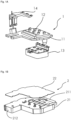
- FIG. 1A shows a first subassembly 1 comprising a first support 11, in this case a cooling module 11, to which an active part 12 of the electrical equipment is fixed.
- the cooling module 11 can be an active module comprising a cooling liquid circulation network, such as a water box for example.
- the active part 12 may comprise an electronic power module of an inverter.
- a power electronic module is an assembly comprising a plurality of semiconductor chips forming an electrical circuit encapsulated in the same envelope. More precisely, in the present context, the electronic power module is for example an assembly comprising components through which passes energy supplying an electrical machine, for example an electric motor system, said components being intended in particular to transform a current direct current into alternating current or vice versa. Such an electronic power module is configured to allow a controlled passage of electrical energy between a high voltage power supply battery and the electrical machine.
- the first subassembly 1 can also include a filtering device 13, to stabilize a signal, in particular a voltage supplied to the active part 12.
- the filtering device 13 is in particular a capacitive link element, also designated “DC-link capacitor " in English.
- the filtering device 13 is for example screwed onto the first support 11, in particular onto a cooling module 11 to which the active device 12 is fixed.
- the first subassembly 1 may also include a first electrical conduction bar 14, also designated “busbar” in English.
- the electrical equipment may be an inverter which supplies a polyphase electric motor system.
- active part 12 is an electronic power module, as explained previously, and such a first electrical conduction bar 14, connected to said electronic power module, is configured to receive phase connectors from the electric motor system in order to supply said electric motor system with energy.
- Said first electrical conduction bar 14 is then commonly referred to as “AC busbar” in English.
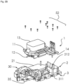
- FIG. 1B shows a second subassembly 2 comprising a second support 21, for example a support plate 21, also designated “bracket” in English.
- a second support 21 for example a support plate 21, also designated “bracket” in English.
- an electronic card 22 is fixed, in particular screwed, to the second support 21.
- the electrical equipment is an inverter
- the electronic card 22 is an electronic card of control of the inverter, and in particular of the electronic power module.
- This part of the second subassembly 2, comprising the electronic card 22, corresponds for example to a low voltage zone of the electrical equipment.
- the second support 21 provides electromagnetic shielding, in particular to protect the active part 12 from its electromagnetic environment, and vice versa.
- the second support 21, relating in particular to a support plate 21, is for example a casting made of a material capable of providing a barrier function with respect to electromagnetic disturbances.
- the second support 21 is made of aluminum.
- the second support 21 comprises for example a flat base plate, from which walls 211, 212 and/or a rib can extend, said walls and said rib being arranged so as to improve the electromagnetic shielding performance of the electrical equipment, once the subassemblies have been assembled.
- FIG. 1C shows a third subassembly 3 comprising a third support 35, for example intended to provide a cover function for the electrical equipment.
- the third subassembly 3 also comprises a second electrical conduction bar 30 fixed, for example screwed, to said third support 35.
- the second electrical conduction bar 30 may comprise electrical conductors 300, also referred to as “leadframes” in English, in which an electrical power signal circulates.
- a signal circulates in said electrical conductors 300, in particular a power signal such as a voltage delivered by a high voltage power supply battery.
- the second electrical conduction bar 30 is intended to partially go around the active part 12.
- the second electrical conduction bar 30 may comprise elements for filtering said power signal, namely, in the example shown, at least one electromagnetic filtering torus 302, 303 and at least one discharge capacitor X, Y.
- the filtering elements ensure the filtering of said power signal.
- the second electrical conduction bar 30 may also include a fuse 301 to ensure that the conduction of the power signal is cut off in the event of a malfunction.
- the third support 35 can also comprise at least one low wall 311 extending orthogonally to said third support 35. This at least one third low wall 311 then contributes to the electromagnetic shielding of the electrical assembly.
- the third support 35 in particular if it performs the function of covering the electrical equipment, may also comprise electrical connectors 351, 352 configured to allow the connection of the electrical equipment to third-party electrical equipment.
- the third support 35 may comprise an electrical connector 351 for connecting the inverter to a high voltage power supply battery, said high voltage battery supplying a direct voltage to the inverter, and a signal connector 352 for exchanging data with third-party electrical equipment, such as an information management system on the state of a vehicle in which said inverter is located for example.
- the second subassembly 2 is assembled to the third subassembly 3.
- the second support 21 is fixed, for example the support plate 21, in particular equipped with an electronic card 22, for example a electronic control card of an electronic power module, to the third support 35 equipped with the second electrical conduction bar 30, said third support 35 being for example intended to provide a cover function for the electrical equipment.
- screws 51 are engaged in barrels 215 of the second support 21 and screwed into corresponding barrels 355 provided on the third support 35.
- FIG. 2B represents the assembly of the first subassembly 1 to the assembly formed by the second and third subassemblies 2, 3.
- the first support 11 is fixed, for example a cooling module 11, in particular a cooling box. water, said first support 11 being in particular equipped with an active part 12, for example an electronic power module, and possibly also equipped with a filtering device 13, for example with a capacitive connecting element, and with a first electrical conduction bar 14, to the second support 21, for example a support plate 21.
- screws 52 are engaged in barrels of the first support 11 and screwed into corresponding barrels provided on the second support 21.
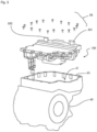
- the electrical assembly 100 formed in accordance with the assembly steps shown in figures 2A And 2B is then mounted in a housing 61 of a housing 60, for example arranged in a part of the chassis also housing, in another dedicated housing, a second piece of electrical equipment.
- the housing 60 comprises a bottom, a side wall and an opening 63 through which said electrical assembly 100 is introduced into the housing 60, such that the third support 35 closes said housing 60.
- the electrical assembly 100 is screwed in the housing by means of screws 53 engaged in respective barrels of said electrical assembly 100 and said housing 60.
- An advantage induced by the implementation of the invention lies in the fact that the production of three independent subassemblies 1, 2, 3 makes it possible to increase the flexibility of the electrical equipment manufacturing process.
- the fact of having independent sub-assemblies 1, 2, 3 also makes it possible to test the proper functioning of each sub-assembly 1, 2, 3 independently, and therefore to reduce the quantity of possible scrap.
- the electrical equipment according to the invention is ultimately represented on the Figure 3 , in exploded view.
- Said electrical equipment for example an inverter, has an advantageous arrangement.
- the assembly is carried out in such a way that the filtering device 13, in this case a capacitive connecting element, is located next to it, substantially in the same plane, with respect to the second electrical conduction bar 30.
- second electrical conduction bar 30 thus bypasses the filtering device 13, which improves the compactness of the electrical equipment.
- the stacking of the first, second and third sub-assembly 1, 2, 3 is carried out in such a way that the third support 35 supports the first and second sub-assemblies 1, 2.
- the third support 35 has a base plate with a first portion which supports the active part 12 of the first subassembly and a second portion, complementary to the first portion, which supports the second electrical conduction bar 30.
- the first portion of the base plate of the third support 35 supports the first and second subassemblies 1, 2.
- the electronic card 22 is inserted between the second support 21 and the third support 35; and the active part 12 is interposed between the second support 21 and the first support 11.
- the filtering device 13 is located on the other side of the first support 11 with respect to the active part 12. This arrangement makes it possible to reduce the size of the electrical assembly obtained.
- the second electrical conduction bar 30 of the third subassembly 3 locates the passage of the power signal on one side. This makes it easy to shield this power signal from the rest of the assembly.
- the second electrical conduction bar may include filtering elements, already mentioned. These filtering elements include in particular a capacitance
- the power signal induces a magnetic field from which it is necessary to protect the other parts of the electrical equipment, in particular the electronic card 22. Still to improve the electromagnetic compatibility performance, it is also necessary to protect the electrical equipment, in particular the electronic card 22, with respect to electromagnetic disturbances coming from the environment of said electrical equipment, in particular induced by third-party electrical equipment intended to operate nearby.
- the second support 21, in this case a support plate 21, notably comprises at least one first wall 211, shown on the figures 1B , 2A And 2B , extending from a base plate towards the third support 35.
- the assembly of the second subassembly 2, comprising in particular said second support 21, to the third subassembly 3, comprising the third support 35, then the assembly of the first subassembly 1, comprising in particular the active part 12, to the assembly formed by the second and third subassemblies 2, 3, are made in such a way that said at least one first wall 211 creates a separation between the second electrical conduction bar 30 and the electronic card 22.
- At least a third wall 311 can extend orthogonally from the third support 35 towards the second support 21, to provide electromagnetic shielding, also for the electronic card 22 notably.
- the electromagnetic disturbances generated by the signal circulating in the second electrical conduction bar 30 and on the signals circulating in the electronic card 22 are reduced.
- Low walls can extend on either side of the base plate of the second support 21 in order to provide electromagnetic shielding.
- at least one second wall 212 can extend from the base plate of the second support 21 in a direction opposite to that in which the at least one first wall 211 extends, so as to provide electromagnetic shielding for the part active 12. With the base plate of the second support 21, this contributes to the electromagnetic shielding between the active part 12 and the electronic card 22. Furthermore, in cooperation with the first support 11, this limits the electromagnetic disturbances of the active part 12 on the environment outside the electrical equipment.
- the assembly of the first subassembly 1 on the assembly formed of the second and third subassemblies 2, 3 is carried out so that the active part 12 is interposed between the second support 21 and the first support 11, itself inserted between the active part 12 and the filtering device 13.
- barrels make it possible to fix the second subassembly 2 to the third subassembly 3, on the one hand, and other barrels make it possible to fix the first subassembly 1 on the second subassembly 2.
- the absence of a through barrel from the first subassembly 1 to the second sub-assembly 2, crossing in particular the second support 21 belonging to the third sub-assembly 3, makes it possible to minimize the propagation of magnetic fields, sources of electromagnetic disturbances, from the active part 12 towards the peripheral electrical connection bar 300, and reciprocally.
Landscapes
- Engineering & Computer Science (AREA)
- Power Engineering (AREA)
- Microelectronics & Electronic Packaging (AREA)
- Physics & Mathematics (AREA)
- Electromagnetism (AREA)
- Inverter Devices (AREA)
Claims (8)
- Elektrische Einheit, die dazu bestimmt ist, in ein elektrisches Gerät montiert zu werden, wobei die Einheit Folgendes beinhaltet:eine erste Untereinheit (1), die einen ersten Träger (11), der einem Kühlmodul entspricht, einen aktiven Teil (12), der ein elektronisches Leistungsmodul eines Wechselrichters beinhaltet, und eine erste elektrische Leiterschiene (14), die dazu bestimmt ist, den aktiven Teil (12) mit mindestens einem ersten Anschluss des elektrischen Geräts zu verbinden, beinhaltet, wobei der aktive Teil (12) und die erste Leiterschiene (14) auf dem ersten Träger (11) montiert sind,eine zweite Untereinheit (2), die einen zweiten Träger (21), insbesondere in Form einer Platte (21), und eine elektronische Karte (22), die einer elektronischen Karte zur Steuerung des Wechselrichters entspricht und dazu konfiguriert ist, den aktiven Teil (12) zu steuern, beinhaltet, wobei die elektronische Karte (22) auf dem zweiten Träger (21) montiert ist, wobei der zweite Träger (21) Befestigungsbereiche (215) beinhaltet,eine dritte Untereinheit (3), die einen dritten Träger (35) und eine zweite elektrische Leiterschiene (30) beinhaltet, wobei die elektrische Leiterschiene (30) auf dem dritten Träger (35) montiert ist, wobei der dritte Träger (35) Befestigungsbereiche (355) beinhaltet,wobei die zweite Untereinheit (2) in den Befestigungsbereichen (355) an der dritten Untereinheit (3) befestigt ist und die erste Untereinheit (1) in den Befestigungsbereichen (215) an der zweiten Untereinheit (2) befestigt ist, um so eine zusammenhängende elektrische Einheit (100) zu bilden, wobei der dritte Träger (35) einen Deckel eines Gehäuses eines elektrischen Geräts bildet,wobei sich eine erste Seite der zweiten Untereinheit (2) gegenüber einer Seite der ersten Untereinheit (1) befindet und sich eine Seite der dritten Untereinheit (3) gegenüber einer zweiten Seite der zweiten Untereinheit (2) befindet, wobei die zweite Seite der ersten Seite gegenüberliegt, sodass die erste, zweite und dritte Untereinheit (1, 2, 3) einen Stapel auf der Seite der dritten Untereinheit (3) bilden.
- Elektrische Einheit (100) nach Anspruch 1, wobei die erste, die zweite und die dritte Untereinheit (1, 2, 3) so gestapelt sind, dass der dritte Träger (35) eine Grundplatte mit einem ersten Abschnitt, der den aktiven Teil (12) der ersten Untereinheit trägt, und einem zweiten Abschnitt, der zu dem ersten Abschnitt komplementär ist und die zweite elektrische Leiterschiene (30) trägt, beinhaltet.
- Elektrisches Gerät, das eine elektrische Einheit (100) nach einem der Ansprüche 1 bis 2 beinhaltet und ein Gehäuse (60) beinhaltet, das eine Aufnahme (61) definiert und eine Öffnung (63) beinhaltet, wobei die elektrische Einheit (100), die die erste, zweite und dritte Untereinheit (1, 2, 3) beinhaltet, so in der Aufnahme (61) angeordnet ist, dass der dritte Träger (35) die Öffnung (63) des Gehäuses (60) verschließt und so einen Deckel des elektrischen Geräts bildet.
- Elektrisches System, das ein erstes elektrisches Gerät nach einem der Ansprüche 1 bis 3 beinhaltet, wobei das Gehäuse des ersten elektrischen Geräts eine zweite Aufnahme beinhaltet, die ein zweites elektrisches Gerät aufnimmt.
- Elektrisches System nach dem vorhergehenden Anspruch, wobei das erste elektrische Gerät einen Wechselrichter bildet und das zweite elektrische Gerät einen Elektromotor bildet, der dazu bestimmt ist, von dem Wechselrichter gesteuert zu werden.
- Verfahren für den Zusammenbau eines elektrischen Geräts nach Anspruch 3, wobei das Verfahren Folgendes beinhaltet:die Herstellung einer ersten Untereinheit (1), die einen ersten Träger (11), einen aktiven Teil (12) und eine erste elektrische Leiterschiene (14), die dazu bestimmt ist, den aktiven Teil (12) mit mindestens einem ersten Anschluss des elektrischen Geräts zu verbinden, beinhaltet,die Herstellung einer zweiten Untereinheit (2), die einen zweiten Träger (21) und eine elektronische Karte (22), die dazu konfiguriert ist, den aktiven Teil (12) zu steuern, beinhaltet,die Herstellung einer dritten Untereinheit (3), die einen dritten Träger (35), der einen Deckel eines Gehäuses des elektrischen Geräts bildet, und eine zweite elektrische Leiterschiene (30) beinhaltet,wobei ein Schritt des Zusammenbauens die Befestigung der zweiten Untereinheit (2) an der dritten Untereinheit (3) und die Befestigung der ersten Untereinheit (1) an der zweiten Untereinheit (2) beinhaltet.
- Verfahren nach Anspruch 6, das Folgendes beinhaltet:die Bereitstellung eines Gehäuses (60), das eine Aufnahme (61) definiert und eine Öffnung (63) beinhaltet,nach dem Zusammenbau der Einheit aus der ersten, zweiten und dritten Untereinheit (1, 2, 3), die Einführung der Einheit in die Aufnahme (61) durch die Öffnung (63), sodass der physische Träger (35) das Verschließen der Öffnung (63) bewirkt.
- Verfahren nach einem der Ansprüche 6 bis 7, wobei eine erste Seite der zweiten Untereinheit auf einer Seite der ersten Untereinheit (1) montiert ist und eine Seite der dritten Untereinheit (3) auf einer zweiten Seite der zweiten Untereinheit (2) montiert ist, wobei die zweite Seite der ersten Seite gegenüberliegt, sodass die erste, zweite und dritte Untereinheit (1, 2, 3) einen Stapel auf der Seite der dritten Untereinheit (3) bilden.
Applications Claiming Priority (1)
| Application Number | Priority Date | Filing Date | Title |
|---|---|---|---|
| FR1873977A FR3091137B1 (fr) | 2018-12-21 | 2018-12-21 | Procédé d’assemblage d’un équipement électrique, notamment d’un onduleur |
Publications (2)
| Publication Number | Publication Date |
|---|---|
| EP3672381A1 EP3672381A1 (de) | 2020-06-24 |
| EP3672381B1 true EP3672381B1 (de) | 2024-05-08 |
Family
ID=66776492
Family Applications (1)
| Application Number | Title | Priority Date | Filing Date |
|---|---|---|---|
| EP19213491.4A Active EP3672381B1 (de) | 2018-12-21 | 2019-12-04 | Zusammenbauverfahren eines elektrischen geräts, insbesondere eines wechselrichters |
Country Status (3)
| Country | Link |
|---|---|
| EP (1) | EP3672381B1 (de) |
| CN (1) | CN111355386A (de) |
| FR (1) | FR3091137B1 (de) |
Families Citing this family (2)
| Publication number | Priority date | Publication date | Assignee | Title |
|---|---|---|---|---|
| FR3140493B1 (fr) | 2022-09-29 | 2025-08-15 | Nidec Psa Emotors | Ensemble de machine électrique tournante comportant un onduleur |
| FR3140494A1 (fr) | 2022-09-29 | 2024-04-05 | Nidec Psa Emotors | Ensemble de machine électrique tournante comportant un onduleur |
Citations (4)
| Publication number | Priority date | Publication date | Assignee | Title |
|---|---|---|---|---|
| US20120045353A1 (en) * | 2009-09-24 | 2012-02-23 | Mitsubishi Heavy Industries, Ltd. | Inverter-integrated electric compressor |
| US20160324039A1 (en) * | 2015-04-28 | 2016-11-03 | Komatsu Ltd. | Cooling Case for Electronic Device, Electronic Device, and Construction Machine |
| US10063121B2 (en) * | 2016-02-29 | 2018-08-28 | Omron Automotive Electronics Co., Ltd. | Electric motor control apparatus |
| US20180303001A1 (en) * | 2010-06-21 | 2018-10-18 | Hitachi Automotive Systems, Ltd. | Power Semiconductor Device and Power Conversion Device |
Family Cites Families (6)
| Publication number | Priority date | Publication date | Assignee | Title |
|---|---|---|---|---|
| JP5511232B2 (ja) * | 2009-06-18 | 2014-06-04 | 三菱重工業株式会社 | インバータモジュールおよびそれを用いたインバータ一体型電動圧縮機 |
| JP4898931B2 (ja) * | 2010-02-10 | 2012-03-21 | 三菱重工業株式会社 | インバータ一体型電動圧縮機 |
| EP2899866B1 (de) * | 2012-09-19 | 2017-05-10 | Nissan Motor Co., Ltd. | Stromwandlervorrichtung zum einbau in ein elektrisch angetriebenes fahrzeug |
| CN105406791A (zh) * | 2014-09-10 | 2016-03-16 | 周旺龙 | 一种电动车辆电机控制器及控制器总成的结构方式 |
| FR3043879B1 (fr) * | 2015-11-13 | 2018-08-24 | Valeo Siemens Eautomotive France Sas | Ensemble formant boitier pour un equipement electrique |
| FR3044842B1 (fr) * | 2015-12-02 | 2021-12-03 | Valeo Systemes De Controle Moteur | Architecture electronique destinee a alimenter une machine electrique pour vehicule automobile |
-
2018
- 2018-12-21 FR FR1873977A patent/FR3091137B1/fr active Active
-
2019
- 2019-12-04 EP EP19213491.4A patent/EP3672381B1/de active Active
- 2019-12-17 CN CN201911301903.2A patent/CN111355386A/zh active Pending
Patent Citations (4)
| Publication number | Priority date | Publication date | Assignee | Title |
|---|---|---|---|---|
| US20120045353A1 (en) * | 2009-09-24 | 2012-02-23 | Mitsubishi Heavy Industries, Ltd. | Inverter-integrated electric compressor |
| US20180303001A1 (en) * | 2010-06-21 | 2018-10-18 | Hitachi Automotive Systems, Ltd. | Power Semiconductor Device and Power Conversion Device |
| US20160324039A1 (en) * | 2015-04-28 | 2016-11-03 | Komatsu Ltd. | Cooling Case for Electronic Device, Electronic Device, and Construction Machine |
| US10063121B2 (en) * | 2016-02-29 | 2018-08-28 | Omron Automotive Electronics Co., Ltd. | Electric motor control apparatus |
Also Published As
| Publication number | Publication date |
|---|---|
| EP3672381A1 (de) | 2020-06-24 |
| FR3091137B1 (fr) | 2021-01-15 |
| CN111355386A (zh) | 2020-06-30 |
| FR3091137A1 (fr) | 2020-06-26 |
Similar Documents
| Publication | Publication Date | Title |
|---|---|---|
| EP3672384B1 (de) | Elektrische anordnung von einer elektrischen stromschiene und eines kühlmoduls | |
| EP3501908B1 (de) | Elektrische ausrüstung mit versetzter wand | |
| EP1861889B1 (de) | Vorrichtung zur stromversorgung eines kraftfahrzeuges | |
| EP3501907B1 (de) | Gehäuseelement einer elektrischen ausstattung, das insbesondere u-förmige magnetteile umfasst | |
| EP3108725B1 (de) | Leistungsverteilerkasten mit einer eingangsleistungssammelschiene | |
| EP3672381A1 (de) | Zusammenbauverfahren eines elektrischen geräts, insbesondere eines wechselrichters | |
| EP3589099B1 (de) | Elektrische ausrüstung, die eine vorrichtung einer halterungsplatte zur ableitung umfasst | |
| EP3501910B1 (de) | Gehäuseelement für elektrische ausrüstung | |
| CA2898070A1 (fr) | Systeme de connexion pour cartes de protection d'un systeme de distribution et rack integrant ledit systeme | |
| EP4527157A1 (de) | Verbinderführung für einen wechselrichter mit einem temperatursensorgehäuse | |
| EP3672386A1 (de) | Elektrische montage mit integrierter elektromagnetischer abschirmmittel | |
| EP3261874B1 (de) | Kondensator gehäuse und kasten eines elektrischen antriebsaggregats | |
| EP3476665B1 (de) | Elektrische isolierleiste, insbesondere für ein elektronisches leistungsmodul eines wechselrichters | |
| EP3646682B1 (de) | Anordnung von teilen und verfahren zur herstellung solch einer anordnung | |
| EP1263095A1 (de) | Lampenfassungseinrichtung in einem Fahrzeug | |
| EP3474025B1 (de) | Messfühler zum messen des ausgangsstroms eines elektrischen systems | |
| EP0145694A2 (de) | Schutzanordnung gegen Störungen und/oder Interferenzen in der Nähe von integrierten Schaltungen | |
| EP3667688A1 (de) | Elektrische einheit, die ein kapazitives element umfasst | |
| EP3668289B1 (de) | Elektrische vorrichtung mit einer aufgefalteten isolierenden folie | |
| WO2019122289A1 (fr) | Barre de connexion electrique | |
| EP1950641B1 (de) | Elektrisches Versorgungsmodul für einem Chassis von Elektronikkarten | |
| EP3727943B1 (de) | Elektrische anschlussleiste für eine elektrische anordnung | |
| FR3047851A1 (fr) | Ensemble electronique d'une machine electrique tournante | |
| WO2026082621A1 (fr) | Convertisseur de puissance, notamment configuré pour être embarqué dans un véhicule automobile | |
| FR3069963A1 (fr) | Connecteur electrique constitutif d'un compresseur electrique et compresseur electrique comprenant un tel connecteur electrique |
Legal Events
| Date | Code | Title | Description |
|---|---|---|---|
| PUAI | Public reference made under article 153(3) epc to a published international application that has entered the european phase |
Free format text: ORIGINAL CODE: 0009012 |
|
| STAA | Information on the status of an ep patent application or granted ep patent |
Free format text: STATUS: THE APPLICATION HAS BEEN PUBLISHED |
|
| AK | Designated contracting states |
Kind code of ref document: A1 Designated state(s): AL AT BE BG CH CY CZ DE DK EE ES FI FR GB GR HR HU IE IS IT LI LT LU LV MC MK MT NL NO PL PT RO RS SE SI SK SM TR |
|
| AX | Request for extension of the european patent |
Extension state: BA ME |
|
| STAA | Information on the status of an ep patent application or granted ep patent |
Free format text: STATUS: REQUEST FOR EXAMINATION WAS MADE |
|
| 17P | Request for examination filed |
Effective date: 20201216 |
|
| RBV | Designated contracting states (corrected) |
Designated state(s): AL AT BE BG CH CY CZ DE DK EE ES FI FR GB GR HR HU IE IS IT LI LT LU LV MC MK MT NL NO PL PT RO RS SE SI SK SM TR |
|
| STAA | Information on the status of an ep patent application or granted ep patent |
Free format text: STATUS: EXAMINATION IS IN PROGRESS |
|
| 17Q | First examination report despatched |
Effective date: 20220310 |
|
| RAP3 | Party data changed (applicant data changed or rights of an application transferred) |
Owner name: VALEO EAUTOMOTIVE FRANCE SAS |
|
| P01 | Opt-out of the competence of the unified patent court (upc) registered |
Effective date: 20230629 |
|
| GRAP | Despatch of communication of intention to grant a patent |
Free format text: ORIGINAL CODE: EPIDOSNIGR1 |
|
| STAA | Information on the status of an ep patent application or granted ep patent |
Free format text: STATUS: GRANT OF PATENT IS INTENDED |
|
| INTG | Intention to grant announced |
Effective date: 20231204 |
|
| GRAS | Grant fee paid |
Free format text: ORIGINAL CODE: EPIDOSNIGR3 |
|
| RBV | Designated contracting states (corrected) |
Designated state(s): AL AT BE BG CH CY CZ DE DK EE ES FI GB GR HR HU IE IS IT LI LT LU LV MC MK MT NL NO PL PT RO RS SE SI SK SM TR |
|
| GRAA | (expected) grant |
Free format text: ORIGINAL CODE: 0009210 |
|
| STAA | Information on the status of an ep patent application or granted ep patent |
Free format text: STATUS: THE PATENT HAS BEEN GRANTED |
|
| AK | Designated contracting states |
Kind code of ref document: B1 Designated state(s): AL AT BE BG CH CY CZ DE DK EE ES FI GB GR HR HU IE IS IT LI LT LU LV MC MK MT NL NO PL PT RO RS SE SI SK SM TR |
|
| REG | Reference to a national code |
Ref country code: GB Ref legal event code: FG4D Free format text: NOT ENGLISH |
|
| REG | Reference to a national code |
Ref country code: CH Ref legal event code: EP |
|
| REG | Reference to a national code |
Ref country code: DE Ref legal event code: R096 Ref document number: 602019051859 Country of ref document: DE |
|
| REG | Reference to a national code |
Ref country code: IE Ref legal event code: FG4D Free format text: LANGUAGE OF EP DOCUMENT: FRENCH |
|
| REG | Reference to a national code |
Ref country code: LT Ref legal event code: MG9D |
|
| RAP2 | Party data changed (patent owner data changed or rights of a patent transferred) |
Owner name: VALEO ELECTRIFICATION |
|
| REG | Reference to a national code |
Ref country code: NL Ref legal event code: MP Effective date: 20240508 |
|
| PG25 | Lapsed in a contracting state [announced via postgrant information from national office to epo] |
Ref country code: IS Free format text: LAPSE BECAUSE OF FAILURE TO SUBMIT A TRANSLATION OF THE DESCRIPTION OR TO PAY THE FEE WITHIN THE PRESCRIBED TIME-LIMIT Effective date: 20240908 |
|
| PG25 | Lapsed in a contracting state [announced via postgrant information from national office to epo] |
Ref country code: BG Free format text: LAPSE BECAUSE OF FAILURE TO SUBMIT A TRANSLATION OF THE DESCRIPTION OR TO PAY THE FEE WITHIN THE PRESCRIBED TIME-LIMIT Effective date: 20240508 |
|
| PG25 | Lapsed in a contracting state [announced via postgrant information from national office to epo] |
Ref country code: FI Free format text: LAPSE BECAUSE OF FAILURE TO SUBMIT A TRANSLATION OF THE DESCRIPTION OR TO PAY THE FEE WITHIN THE PRESCRIBED TIME-LIMIT Effective date: 20240508 Ref country code: HR Free format text: LAPSE BECAUSE OF FAILURE TO SUBMIT A TRANSLATION OF THE DESCRIPTION OR TO PAY THE FEE WITHIN THE PRESCRIBED TIME-LIMIT Effective date: 20240508 |
|
| PG25 | Lapsed in a contracting state [announced via postgrant information from national office to epo] |
Ref country code: GR Free format text: LAPSE BECAUSE OF FAILURE TO SUBMIT A TRANSLATION OF THE DESCRIPTION OR TO PAY THE FEE WITHIN THE PRESCRIBED TIME-LIMIT Effective date: 20240809 |
|
| PG25 | Lapsed in a contracting state [announced via postgrant information from national office to epo] |
Ref country code: PT Free format text: LAPSE BECAUSE OF FAILURE TO SUBMIT A TRANSLATION OF THE DESCRIPTION OR TO PAY THE FEE WITHIN THE PRESCRIBED TIME-LIMIT Effective date: 20240909 |
|
| REG | Reference to a national code |
Ref country code: AT Ref legal event code: MK05 Ref document number: 1686058 Country of ref document: AT Kind code of ref document: T Effective date: 20240508 |
|
| PG25 | Lapsed in a contracting state [announced via postgrant information from national office to epo] |
Ref country code: NL Free format text: LAPSE BECAUSE OF FAILURE TO SUBMIT A TRANSLATION OF THE DESCRIPTION OR TO PAY THE FEE WITHIN THE PRESCRIBED TIME-LIMIT Effective date: 20240508 |
|
| PG25 | Lapsed in a contracting state [announced via postgrant information from national office to epo] |
Ref country code: ES Free format text: LAPSE BECAUSE OF FAILURE TO SUBMIT A TRANSLATION OF THE DESCRIPTION OR TO PAY THE FEE WITHIN THE PRESCRIBED TIME-LIMIT Effective date: 20240508 |
|
| PG25 | Lapsed in a contracting state [announced via postgrant information from national office to epo] |
Ref country code: AT Free format text: LAPSE BECAUSE OF FAILURE TO SUBMIT A TRANSLATION OF THE DESCRIPTION OR TO PAY THE FEE WITHIN THE PRESCRIBED TIME-LIMIT Effective date: 20240508 |
|
| PG25 | Lapsed in a contracting state [announced via postgrant information from national office to epo] |
Ref country code: PL Free format text: LAPSE BECAUSE OF FAILURE TO SUBMIT A TRANSLATION OF THE DESCRIPTION OR TO PAY THE FEE WITHIN THE PRESCRIBED TIME-LIMIT Effective date: 20240508 |
|
| PG25 | Lapsed in a contracting state [announced via postgrant information from national office to epo] |
Ref country code: LV Free format text: LAPSE BECAUSE OF FAILURE TO SUBMIT A TRANSLATION OF THE DESCRIPTION OR TO PAY THE FEE WITHIN THE PRESCRIBED TIME-LIMIT Effective date: 20240508 |
|
| PG25 | Lapsed in a contracting state [announced via postgrant information from national office to epo] |
Ref country code: PT Free format text: LAPSE BECAUSE OF FAILURE TO SUBMIT A TRANSLATION OF THE DESCRIPTION OR TO PAY THE FEE WITHIN THE PRESCRIBED TIME-LIMIT Effective date: 20240909 Ref country code: PL Free format text: LAPSE BECAUSE OF FAILURE TO SUBMIT A TRANSLATION OF THE DESCRIPTION OR TO PAY THE FEE WITHIN THE PRESCRIBED TIME-LIMIT Effective date: 20240508 Ref country code: NO Free format text: LAPSE BECAUSE OF FAILURE TO SUBMIT A TRANSLATION OF THE DESCRIPTION OR TO PAY THE FEE WITHIN THE PRESCRIBED TIME-LIMIT Effective date: 20240808 Ref country code: NL Free format text: LAPSE BECAUSE OF FAILURE TO SUBMIT A TRANSLATION OF THE DESCRIPTION OR TO PAY THE FEE WITHIN THE PRESCRIBED TIME-LIMIT Effective date: 20240508 Ref country code: LV Free format text: LAPSE BECAUSE OF FAILURE TO SUBMIT A TRANSLATION OF THE DESCRIPTION OR TO PAY THE FEE WITHIN THE PRESCRIBED TIME-LIMIT Effective date: 20240508 Ref country code: IS Free format text: LAPSE BECAUSE OF FAILURE TO SUBMIT A TRANSLATION OF THE DESCRIPTION OR TO PAY THE FEE WITHIN THE PRESCRIBED TIME-LIMIT Effective date: 20240908 Ref country code: HR Free format text: LAPSE BECAUSE OF FAILURE TO SUBMIT A TRANSLATION OF THE DESCRIPTION OR TO PAY THE FEE WITHIN THE PRESCRIBED TIME-LIMIT Effective date: 20240508 Ref country code: GR Free format text: LAPSE BECAUSE OF FAILURE TO SUBMIT A TRANSLATION OF THE DESCRIPTION OR TO PAY THE FEE WITHIN THE PRESCRIBED TIME-LIMIT Effective date: 20240809 Ref country code: FI Free format text: LAPSE BECAUSE OF FAILURE TO SUBMIT A TRANSLATION OF THE DESCRIPTION OR TO PAY THE FEE WITHIN THE PRESCRIBED TIME-LIMIT Effective date: 20240508 Ref country code: ES Free format text: LAPSE BECAUSE OF FAILURE TO SUBMIT A TRANSLATION OF THE DESCRIPTION OR TO PAY THE FEE WITHIN THE PRESCRIBED TIME-LIMIT Effective date: 20240508 Ref country code: BG Free format text: LAPSE BECAUSE OF FAILURE TO SUBMIT A TRANSLATION OF THE DESCRIPTION OR TO PAY THE FEE WITHIN THE PRESCRIBED TIME-LIMIT Effective date: 20240508 Ref country code: AT Free format text: LAPSE BECAUSE OF FAILURE TO SUBMIT A TRANSLATION OF THE DESCRIPTION OR TO PAY THE FEE WITHIN THE PRESCRIBED TIME-LIMIT Effective date: 20240508 Ref country code: RS Free format text: LAPSE BECAUSE OF FAILURE TO SUBMIT A TRANSLATION OF THE DESCRIPTION OR TO PAY THE FEE WITHIN THE PRESCRIBED TIME-LIMIT Effective date: 20240808 |
|
| PG25 | Lapsed in a contracting state [announced via postgrant information from national office to epo] |
Ref country code: DK Free format text: LAPSE BECAUSE OF FAILURE TO SUBMIT A TRANSLATION OF THE DESCRIPTION OR TO PAY THE FEE WITHIN THE PRESCRIBED TIME-LIMIT Effective date: 20240508 |
|
| PG25 | Lapsed in a contracting state [announced via postgrant information from national office to epo] |
Ref country code: EE Free format text: LAPSE BECAUSE OF FAILURE TO SUBMIT A TRANSLATION OF THE DESCRIPTION OR TO PAY THE FEE WITHIN THE PRESCRIBED TIME-LIMIT Effective date: 20240508 |
|
| PG25 | Lapsed in a contracting state [announced via postgrant information from national office to epo] |
Ref country code: CZ Free format text: LAPSE BECAUSE OF FAILURE TO SUBMIT A TRANSLATION OF THE DESCRIPTION OR TO PAY THE FEE WITHIN THE PRESCRIBED TIME-LIMIT Effective date: 20240508 |
|
| PG25 | Lapsed in a contracting state [announced via postgrant information from national office to epo] |
Ref country code: SK Free format text: LAPSE BECAUSE OF FAILURE TO SUBMIT A TRANSLATION OF THE DESCRIPTION OR TO PAY THE FEE WITHIN THE PRESCRIBED TIME-LIMIT Effective date: 20240508 Ref country code: RO Free format text: LAPSE BECAUSE OF FAILURE TO SUBMIT A TRANSLATION OF THE DESCRIPTION OR TO PAY THE FEE WITHIN THE PRESCRIBED TIME-LIMIT Effective date: 20240508 |
|
| PG25 | Lapsed in a contracting state [announced via postgrant information from national office to epo] |
Ref country code: SM Free format text: LAPSE BECAUSE OF FAILURE TO SUBMIT A TRANSLATION OF THE DESCRIPTION OR TO PAY THE FEE WITHIN THE PRESCRIBED TIME-LIMIT Effective date: 20240508 |
|
| PG25 | Lapsed in a contracting state [announced via postgrant information from national office to epo] |
Ref country code: SM Free format text: LAPSE BECAUSE OF FAILURE TO SUBMIT A TRANSLATION OF THE DESCRIPTION OR TO PAY THE FEE WITHIN THE PRESCRIBED TIME-LIMIT Effective date: 20240508 Ref country code: SK Free format text: LAPSE BECAUSE OF FAILURE TO SUBMIT A TRANSLATION OF THE DESCRIPTION OR TO PAY THE FEE WITHIN THE PRESCRIBED TIME-LIMIT Effective date: 20240508 Ref country code: RO Free format text: LAPSE BECAUSE OF FAILURE TO SUBMIT A TRANSLATION OF THE DESCRIPTION OR TO PAY THE FEE WITHIN THE PRESCRIBED TIME-LIMIT Effective date: 20240508 Ref country code: EE Free format text: LAPSE BECAUSE OF FAILURE TO SUBMIT A TRANSLATION OF THE DESCRIPTION OR TO PAY THE FEE WITHIN THE PRESCRIBED TIME-LIMIT Effective date: 20240508 Ref country code: DK Free format text: LAPSE BECAUSE OF FAILURE TO SUBMIT A TRANSLATION OF THE DESCRIPTION OR TO PAY THE FEE WITHIN THE PRESCRIBED TIME-LIMIT Effective date: 20240508 Ref country code: CZ Free format text: LAPSE BECAUSE OF FAILURE TO SUBMIT A TRANSLATION OF THE DESCRIPTION OR TO PAY THE FEE WITHIN THE PRESCRIBED TIME-LIMIT Effective date: 20240508 |
|
| PG25 | Lapsed in a contracting state [announced via postgrant information from national office to epo] |
Ref country code: IT Free format text: LAPSE BECAUSE OF FAILURE TO SUBMIT A TRANSLATION OF THE DESCRIPTION OR TO PAY THE FEE WITHIN THE PRESCRIBED TIME-LIMIT Effective date: 20240508 |
|
| REG | Reference to a national code |
Ref country code: DE Ref legal event code: R097 Ref document number: 602019051859 Country of ref document: DE |
|
| PLBE | No opposition filed within time limit |
Free format text: ORIGINAL CODE: 0009261 |
|
| STAA | Information on the status of an ep patent application or granted ep patent |
Free format text: STATUS: NO OPPOSITION FILED WITHIN TIME LIMIT |
|
| 26N | No opposition filed |
Effective date: 20250211 |
|
| PG25 | Lapsed in a contracting state [announced via postgrant information from national office to epo] |
Ref country code: SI Free format text: LAPSE BECAUSE OF FAILURE TO SUBMIT A TRANSLATION OF THE DESCRIPTION OR TO PAY THE FEE WITHIN THE PRESCRIBED TIME-LIMIT Effective date: 20240508 |
|
| PG25 | Lapsed in a contracting state [announced via postgrant information from national office to epo] |
Ref country code: MC Free format text: LAPSE BECAUSE OF FAILURE TO SUBMIT A TRANSLATION OF THE DESCRIPTION OR TO PAY THE FEE WITHIN THE PRESCRIBED TIME-LIMIT Effective date: 20240508 |
|
| REG | Reference to a national code |
Ref country code: CH Ref legal event code: PL |
|
| PG25 | Lapsed in a contracting state [announced via postgrant information from national office to epo] |
Ref country code: LU Free format text: LAPSE BECAUSE OF NON-PAYMENT OF DUE FEES Effective date: 20241204 |
|
| GBPC | Gb: european patent ceased through non-payment of renewal fee |
Effective date: 20241204 |
|
| PG25 | Lapsed in a contracting state [announced via postgrant information from national office to epo] |
Ref country code: SE Free format text: LAPSE BECAUSE OF FAILURE TO SUBMIT A TRANSLATION OF THE DESCRIPTION OR TO PAY THE FEE WITHIN THE PRESCRIBED TIME-LIMIT Effective date: 20240508 |
|
| REG | Reference to a national code |
Ref country code: BE Ref legal event code: MM Effective date: 20241231 |
|
| PG25 | Lapsed in a contracting state [announced via postgrant information from national office to epo] |
Ref country code: GB Free format text: LAPSE BECAUSE OF NON-PAYMENT OF DUE FEES Effective date: 20241204 Ref country code: BE Free format text: LAPSE BECAUSE OF NON-PAYMENT OF DUE FEES Effective date: 20241231 |
|
| PG25 | Lapsed in a contracting state [announced via postgrant information from national office to epo] |
Ref country code: CH Free format text: LAPSE BECAUSE OF NON-PAYMENT OF DUE FEES Effective date: 20241231 |
|
| PG25 | Lapsed in a contracting state [announced via postgrant information from national office to epo] |
Ref country code: IE Free format text: LAPSE BECAUSE OF NON-PAYMENT OF DUE FEES Effective date: 20241204 |
|
| PG25 | Lapsed in a contracting state [announced via postgrant information from national office to epo] |
Ref country code: CY Free format text: LAPSE BECAUSE OF FAILURE TO SUBMIT A TRANSLATION OF THE DESCRIPTION OR TO PAY THE FEE WITHIN THE PRESCRIBED TIME-LIMIT; INVALID AB INITIO Effective date: 20191204 |
|
| PGFP | Annual fee paid to national office [announced via postgrant information from national office to epo] |
Ref country code: DE Payment date: 20251231 Year of fee payment: 7 |