EP3672380A1 - Server-computersystem mit rotierendem träger - Google Patents
Server-computersystem mit rotierendem träger Download PDFInfo
- Publication number
- EP3672380A1 EP3672380A1 EP19180568.8A EP19180568A EP3672380A1 EP 3672380 A1 EP3672380 A1 EP 3672380A1 EP 19180568 A EP19180568 A EP 19180568A EP 3672380 A1 EP3672380 A1 EP 3672380A1
- Authority
- EP
- European Patent Office
- Prior art keywords
- carrier
- chassis
- computer system
- server computer
- length
- Prior art date
- Legal status (The legal status is an assumption and is not a legal conclusion. Google has not performed a legal analysis and makes no representation as to the accuracy of the status listed.)
- Granted
Links
Images


Classifications
-
- H—ELECTRICITY
- H05—ELECTRIC TECHNIQUES NOT OTHERWISE PROVIDED FOR
- H05K—PRINTED CIRCUITS; CASINGS OR CONSTRUCTIONAL DETAILS OF ELECTRIC APPARATUS; MANUFACTURE OF ASSEMBLAGES OF ELECTRICAL COMPONENTS
- H05K5/00—Casings, cabinets or drawers for electric apparatus
- H05K5/02—Details
- H05K5/0217—Mechanical details of casings
- H05K5/0226—Hinges
-
- H—ELECTRICITY
- H05—ELECTRIC TECHNIQUES NOT OTHERWISE PROVIDED FOR
- H05K—PRINTED CIRCUITS; CASINGS OR CONSTRUCTIONAL DETAILS OF ELECTRIC APPARATUS; MANUFACTURE OF ASSEMBLAGES OF ELECTRICAL COMPONENTS
- H05K7/00—Constructional details common to different types of electric apparatus
- H05K7/14—Mounting supporting structure in casing or on frame or rack
- H05K7/1485—Servers; Data center rooms, e.g. 19-inch computer racks
- H05K7/1488—Cabinets therefor, e.g. chassis or racks or mechanical interfaces between blades and support structures
- H05K7/1489—Cabinets therefor, e.g. chassis or racks or mechanical interfaces between blades and support structures characterized by the mounting of blades therein, e.g. brackets, rails, trays
-
- G—PHYSICS
- G06—COMPUTING OR CALCULATING; COUNTING
- G06F—ELECTRIC DIGITAL DATA PROCESSING
- G06F1/00—Details not covered by groups G06F3/00 - G06F13/00 and G06F21/00
- G06F1/16—Constructional details or arrangements
- G06F1/18—Packaging or power distribution
- G06F1/183—Internal mounting support structures, e.g. for supporting printed circuit boards
-
- G—PHYSICS
- G11—INFORMATION STORAGE
- G11B—INFORMATION STORAGE BASED ON RELATIVE MOVEMENT BETWEEN RECORD CARRIER AND TRANSDUCER
- G11B33/00—Constructional parts, details or accessories not provided for in the other groups of this subclass
- G11B33/02—Cabinets; Cases; Stands; Disposition of apparatus therein or thereon
- G11B33/04—Cabinets; Cases; Stands; Disposition of apparatus therein or thereon modified to store record carriers
- G11B33/0405—Cabinets; Cases; Stands; Disposition of apparatus therein or thereon modified to store record carriers for storing discs
- G11B33/0433—Multiple disc containers
-
- H—ELECTRICITY
- H05—ELECTRIC TECHNIQUES NOT OTHERWISE PROVIDED FOR
- H05K—PRINTED CIRCUITS; CASINGS OR CONSTRUCTIONAL DETAILS OF ELECTRIC APPARATUS; MANUFACTURE OF ASSEMBLAGES OF ELECTRICAL COMPONENTS
- H05K7/00—Constructional details common to different types of electric apparatus
- H05K7/14—Mounting supporting structure in casing or on frame or rack
- H05K7/1401—Mounting supporting structure in casing or on frame or rack comprising clamping or extracting means
-
- H—ELECTRICITY
- H05—ELECTRIC TECHNIQUES NOT OTHERWISE PROVIDED FOR
- H05K—PRINTED CIRCUITS; CASINGS OR CONSTRUCTIONAL DETAILS OF ELECTRIC APPARATUS; MANUFACTURE OF ASSEMBLAGES OF ELECTRICAL COMPONENTS
- H05K7/00—Constructional details common to different types of electric apparatus
- H05K7/14—Mounting supporting structure in casing or on frame or rack
- H05K7/1462—Mounting supporting structure in casing or on frame or rack for programmable logic controllers [PLC] for automation or industrial process control
- H05K7/1474—Mounting of modules, e.g. on a base or rail or wall
-
- H—ELECTRICITY
- H05—ELECTRIC TECHNIQUES NOT OTHERWISE PROVIDED FOR
- H05K—PRINTED CIRCUITS; CASINGS OR CONSTRUCTIONAL DETAILS OF ELECTRIC APPARATUS; MANUFACTURE OF ASSEMBLAGES OF ELECTRICAL COMPONENTS
- H05K7/00—Constructional details common to different types of electric apparatus
- H05K7/14—Mounting supporting structure in casing or on frame or rack
- H05K7/1485—Servers; Data center rooms, e.g. 19-inch computer racks
- H05K7/1487—Blade assemblies, e.g. blade cases or inner arrangements within a blade
-
- H—ELECTRICITY
- H05—ELECTRIC TECHNIQUES NOT OTHERWISE PROVIDED FOR
- H05K—PRINTED CIRCUITS; CASINGS OR CONSTRUCTIONAL DETAILS OF ELECTRIC APPARATUS; MANUFACTURE OF ASSEMBLAGES OF ELECTRICAL COMPONENTS
- H05K7/00—Constructional details common to different types of electric apparatus
- H05K7/14—Mounting supporting structure in casing or on frame or rack
- H05K7/16—Mounting supporting structure in casing or on frame or rack on hinges or pivots
Definitions
- the present invention relates to a carrier configured to hold computer components within a computer system, and more specifically, to a space-saving carrier within the computer system.
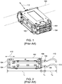
- FIG. 1 illustrates a conventional carrier 102 within a chassis 100 of a conventional server computer system.
- the conventional carrier 102 houses two hot-swappable storage devices 104.
- the carrier 102 has a length L1, which is the direction in which the storage devices 104 extend through the carrier 102, and from which they can be removed from the carrier 102.
- the conventional carrier 102 is designed to fit within the chassis of the conventional server computer system so that the length L1 is parallel to the length of the chassis. This presents the storage devices 104 to the front of the chassis for removal and insertion in the direction of arrow 112.
- This conventional arrangement can occupy a majority (if not all) of the length of a chassis of the server computer system.
- the length is taken up by the length L1 of the carrier 102 holding the storage devices 104; the length L2 of the connector 106 connected to an interface board 108; and the length L3 of cables 110 running the length of the chassis, which connects the storage devices 104 to the server computer system.
- the present disclosure provides for a carrier that extends orthogonally or obliquely within the chassis of a server computer system.
- the carrier is configured to rotate. Rotation of the carrier from a first position within the chassis to a second position, extends one end of the carrier outside of the chassis. In the second position, the computer components can be removed from, or inserted into, the carrier.
- the carrier having the orthogonal or oblique arrangement of the carrier provides space savings within the server computer system. Additionally, the carrier still provides the ability to hot-swap computer components from the server computer system.
- a server computer system contains a chassis.
- the first chassis has a first chassis end, a second chassis end, and a chassis length from the first chassis end to the second chassis end.
- the server computer system further includes a carrier.
- the carrier has a first carrier end, a second carrier end, and a carrier length from the first carrier end to the second carrier end.
- the carrier is configured to house one or more computer components, and allows the one or more computer components to be removed from the first carrier end.
- the server computer system further includes a pivot member configured to connect the carrier to the chassis. The pivot member is further configured to allow the carrier to rotate between a first position, with the first carrier end within the chassis, and a second position with the first carrier end sticking out of the chassis.
- the carrier length can be orthogonal or oblique to the chassis length with the carrier in the first position.
- the pivot member can removably couple the carrier to the chassis.
- the pivot member can be, for example, a screw, a nail, or a post.
- the pivot member can fixedly couple the carrier to the chassis.
- the pivot member can be, for example, a rivet.
- the server computer system can further include at least one fastener configured to inhibit the carrier from rotating between the first position and the second position, with the at least one fastener in a coupled position.
- the carrier can include a flange.
- the at least one fastener can interface with the flange and the chassis in the coupled position to inhibit the carrier from rotating between the first position and the second position.
- the at least one fastener can be configured to allow the carrier to rotate between the first position and the second position, with the at least one fastener in a released position.
- the one or more computer components can be a plurality of hot-swappable storage devices.
- the first carrier end can stick out of the first chassis end in the second position.
- the first chassis end can be at the front of the chassis, with the chassis located within a rackmount server chassis.
- the carrier can be configured to allow the one or more computer components to be removed by sliding out from the first carrier end.
- the server computer system can further include an interface board coupled to the carrier.
- the interface board can have a first side with one or more connectors configured to interface with the one or more components, and a second side with one or more connectors configured to interface with one or more cables of the server computer system.
- the first carrier end can stick out of the first chassis end in the second position, and the interface board can be connected to the carrier at the second carrier end.
- a carrier for housing one or more computer components within a server computer system has a first end, a second end, and a length from the first end to the second end.
- the carrier further includes a pivot member configured to connect the housing to a chassis of the server computer system.
- the pivot member is further configured to allow the housing to rotate between a first position with the first end within the chassis, and a second position with the first end sticking out of the chassis.
- the carrier further includes at least one fastener configured to inhibit the housing from rotating between the first position and the second position, with the at least one fastener in a coupled position.
- the housing can include a flange.
- the at least one fastener can interface with the flange and the chassis in the coupled position to inhibit the carrier from rotating between the first position and the second position.
- the carrier can further include an interface board coupled to the housing.
- the interface board can have a first side with one or more connectors configured to interface with the one or more components, and a second side with one or more connectors configured to interface with one or more cables of the server computer system.
- the pivot member can removably couple the housing to the chassis. Alternatively, the pivot member can fixedly couple the housing to the chassis.
- the terms “computing device,” “computing system,” and “computer system” refer to any electronically-powered or battery-powered equipment that has hardware, software, and/or firmware components, where the software and/or firmware components can be configured for operating features on the device.
- the term “operating environment” can refer to any operating system or environment that functions to allow software to run on a computer system.
- the present disclosure provides for a carrier extends orthogonally or obliquely within the chassis of a server computer system.
- the orthogonal or oblique arrangement of the carrier provides space savings within the server computer system. Additionally, the carrier still provides the ability to hot-swap computer components from the server computer system.
- the carrier is configured to be rotatable within the chassis.
- the rotation allows the carrier to be orthogonal or oblique in the chassis for space savings but still be able to provide for the hot-swapping of computer components.
- the carrier within the chassis in a first position provides space savings.
- the carrier rotated to a second position, with one end partially sticking out from the chassis, provides access for removal and insertion of computer components from the housing.
- the carrier is connected to the chassis by a pivot member. The carrier rotates about the pivot member to rotate from the first position to and second position, and back.
- FIGS. 3A and 3B illustrate an isometric view and an end view, respectively, of a carrier 202 according to one embodiment of the present disclosure.
- the carrier 202 has opposite walls 204a and 204b connected to a plate 206.
- the walls 204a and 204b define slots 208 that accept computer components, such as the illustrated storage devices 104.
- the walls 204a and 204b, and the carrier 202 in general, can include more or less slots 208 to enclose more or less storage devices 104.
- the carrier 202 can enclose various other computer components, not just storage devices.
- the computer components can be any hot-swappable component.
- the carrier 202 includes ends 210a and 210b.
- the end 210a is open to allow the computer components to be slid into and out of the slots 208 of the carrier 202.
- the end 210b includes an interface board 212 for connecting the computer components 104 to the server computer system ( FIGS. 4A-5B , discussed below).
- the interface board 212 includes interfaces (not shown) on a component side (e.g., facing the carrier 202) to connect to the computer components 104; and interfaces 214 on a chassis side (e.g., facing away from the carrier 202) to connect to cables (discussed below) of the server computer system.
- the carrier 202 can include a plate 216 for extra rigidity.
- the plate 216 can be omitted.
- the plate 206 includes a flange 218. As shown in FIG. 3A , the flange 218 extends out beyond the computer components 104. In one or more embodiments, rather than having a flat front, the front 218a of the flange 218 can be curved or angled to reduce the clearance needed for the flange 218, when the carrier 202 is rotated between the first and second positions, discussed below.
- the flange 218 includes one or more apertures 222 ( FIG. 3B ) that accept one or more fasteners 220. The fasteners 220 are configured to secure the carrier 202 within a chassis ( FIGS. 4A-5B , discussed below) and inhibit the carrier 202 from rotating between first and second positions, described below.
- the plate 206 has an aperture 224 at the end 210b opposite from the flange 218.
- the aperture 224 allows a pivot member (discussed below) to connect the carrier 202 to a chassis, and also allow the carrier 202 to pivot about the pivot member, as further described below.
- FIG. 4A illustrates the carrier 202 in a first position and connected to a chassis 430 of a server computer system, according to one embodiment of the present disclosure.
- FIG. 4B illustrates the carrier 202 connected to the chassis 430 in a second position.
- the carrier 202 is connected to the chassis 430 by a pivot member 432 extending through the aperture 224.
- the pivot member 432 allows the carrier 202 to rotate from a first position, as shown in FIG. 4A , to a second position, as shown in FIG. 4B .
- the pivot member 432 can removably couple the carrier 202 to the chassis 430.
- the pivot member 432 can be configured to allow the carrier 202 to disengage from the chassis 430. In which case, the carrier 202 can be removed from the chassis 430.
- a pivot member 432 that removably couples the carrier 202 to the chassis 430 can be, for example, a screw, a nail, a post, or any other mechanical fastener that allows the carrier 202 to disengage and be removed from the chassis 430.
- the pivot member 432 can fixedly couple the carrier 202 to the chassis 430.
- the pivot member 432 can be configured to inhibit the carrier 202 from disengaging from the chassis 430.
- a pivot member 432 that fixedly couples the carrier 202 to the chassis 430 can be, for example, a rivet or any other fastener that inhibits the carrier 202 from being removed from the chassis 430 without, for example, damaging or destroying the pivot member 432.
- the carrier 202 With the carrier 202 in the first position, as illustrated in FIG. 4A , the carrier 202 is entirely enclosed within the chassis 430. However, with the carrier 202 rotated about the pivot member 432 to the second position, as illustrated in FIG. 4B , the carrier 202 partially extends out from the chassis 430.
- the interface board 212 allows the cables 110 of the server computer system to remain connected to the carrier 202 to maintain a connection within the storage devices 104 within the carrier.
- the carrier 202 being enclosed within the chassis 430 in the first position, and partially extending out of the chassis 430 in the second position, is further shown in FIGS. 5A and 5B .
- FIG. 5A illustrates an isometric view of the first position of the carrier 202 relative to the chassis 430.
- FIG. 5B illustrates an isometric view of the second position of the carrier 202 partially rotated out from the chassis 430.
- FIG. 5C illustrates a detailed isometric view of the portion 5C of FIG. 5A .
- the entire carrier 202 is within the chassis 430 in the first position and connected to the chassis 430 by the pivot member 432.
- the length L4 of the carrier 202 is orthogonal to the length L5 of the chassis 430.
- the length L4 of the carrier 202 being orthogonal to the length L5 of the chassis 430, takes up less depth within the chassis 430 than if the length L4 is parallel to the length L5.
- the length of the carrier is parallel to the length of the chassis, not orthogonal.
- the length L1 can be 140 mm; the length L2 can be 20 mm; and the length L3 can be 40 mm.
- the total length of the conventional carrier 102 requires is about 200 mm.
- the length L1 of the conventional carrier 102 arranged parallel to the length L5 of the chassis 430 the conventional carrier 102 would require a majority of the depth of the chassis 430.
- the carrier 202 merely requires the width of the carrier 202, which can be about 80 mm.
- the orthogonal arrangement of the carrier 202 within the chassis 430 conserves about 100 mm to 120 mm of depth within the chassis for other computer components.
- the carrier 202 is still configured to provide access to computer components housed within the carrier 202 (e.g., storage devices 104) by being able to rotate relative to the chassis 430.
- the carrier 202 is configured to rotate about the pivot member 432 in the direction of arrow 434 from the first position ( FIG. 5A ) to the second position ( FIG. 5B ).
- the end 210a of the carrier 202 extends out from the chassis 430.
- This second position provides access to the storage devices 104 that are within the carrier 202.
- one or more of the storage devices 104 can be removed from carrier 202, as shown by the arrow 436.
- the storage devices 104 remaining within the carrier 202 can remain connected to the server computer system, based on the cables 110 and the interface board 212 ( FIG. 4B ).
- the cables 110 can have slack that is taken up with the carrier 202 in the second position and still be connected to the interface.
- the carriers 202 are illustrated as being rotated from the center of the chassis 430 in FIG. 5B , alternatively, arrangement of the carriers 202 in the chassis 430 can be reversed. Specifically, the carriers 202 can be rotated from the sides of the chassis 430. The carrier 202 is able to rotate enough to allow for removal of the storage devices 104. Thus, in one or more embodiments, the carrier 202 is able to rotate about the width of the storage devices 104 so that they clear the other components within the chassis 430, such as the other carrier 202 illustrated in FIG. 5B . However, the carrier 202 can rotate more than the width of the storage device 104. For example, the carrier can rotate up to or beyond 90°. The rotation can be limited only by, for example, the length of the cables 110, the chassis 430 abutting the carrier 202, and the like, if the rotation is limited at all.
- the space savings that are achieved by the length L4 of the carrier 202 being orthogonal to the length L5 of the chassis provides additional space within the chassis 430 for additional computer components.
- the width W1 of the chassis 430 compared to the length L4 of the carrier 202 can provide for a second carrier 202 within the chassis 430, as shown in FIGS. 5A and 5B .
- the carrier 202 can include one or more fasteners 220 that secure the carrier 202 to the chassis 430 and inhibit movement between the first and second positions.
- the fastener 220 With the carrier 202 in the first position ( FIG. 5A ), the fastener 220 can secure the flange 218 to the chassis 430.
- the fastener 220 can be in a coupled position with the carrier 202 in the first position. This inhibits the flange 218 and the carrier 202 from rotating between the first and second positions. Changing the fastener 220 to a de-coupled or released position allows the carrier 202 to rotate from the first position to the second position ( FIG. 5B ).
- the flange 218 can have more than one fastener 220, as shown in FIG. 3B .
- the fastener 220 can be any mechanical fastener that permits the flange 218 to be coupled to, and de-coupled from (e.g., released), the chassis 430.
- the fastener 220 can be a screw, a hook, and the like. Further, there can be more than one fastener 220.
- the chassis 430 can have a track or guide that can assist the carrier 202 rotating relative to the chassis 430.
- the carrier 202 can have a projection that interfaces with the track or guide to assist the rotation of the carrier 202.
- the track or guide can be optional, particularly depending on the amount of available space within the chassis 430.
- FIG. 6 illustrates a carrier 602 according to another embodiment of the present disclosure.
- the carrier 602 has similar features as the carrier 202 discussed above. Thus, similar features are numbered according to a similar numbering scheme.
- the disclosure above with respect to the carrier 202 and its corresponding features applies to the features of the carrier 602, unless otherwise noted.
- the carrier 202 arranges the storage devices 104 adjacent to each other vertically in a horizontal orientation, whereas the carrier 602 arranges the storage devices 104 adjacent to each other horizontally in vertical orientation.
- the carrier 602 has opposite walls 604a and 604b (not shown) connected to a plate 606 (not shown).
- the walls 604a and 604b and the plate 606 are similar to the walls 204a and 204b and the plate 206 except rotated 90 degrees; such that the walls 604a and 604b define the top and bottom, respectively, of the carrier 602, and the plate 606 defines the side of the carrier 606.
- the walls 604a and 604b define slots 608 that accept computer components, such as the illustrated storage devices 104. Although two storage devices 104 are illustrated, the walls 604a and 604b, and the carrier 602 in general, can include more or less slots 608 to enclose more or less storage devices 104. Further, although storage devices 104 are shown, the carrier 602 can enclose various other computer components, not just storage devices. In one or more embodiments, the computer components can be any hot-swappable component.
- the carrier 602 includes ends 610a and 610b.
- the end 610a is open to allow the computer components to be slid into and out of the slots 608 of the carrier 602.
- the end 610b includes an interface board 612 for connecting the computer components 104 to the server computer system ( FIGS. 7A and 7B , discussed below).
- the interface board 612 includes interfaces (not shown) on a component side (e.g., facing the carrier 602) to connect to the computer components 104; and interfaces 614 on a chassis side (e.g., facing away from the carrier 602) to connect to cables (discussed below) of the server computer system.
- the carrier 602 can include a plate 616 for extra rigidity.
- the plate 616 can be omitted.
- the wall 604a includes a flange 618.
- the flange 618 extends out beyond the computer components 104.
- the flange 618 includes one or more apertures 622 that accept one or more fasteners 620.
- the fasteners 620 are configured to secure the carrier 602 within a chassis ( FIGS. 7A and 7B , discussed below) and inhibit the carrier 602 from rotating between first and second positions, described below.
- the wall 604a has an aperture 624 at the end 610b opposite from the flange 618.
- the aperture 624 allows a pivot member (discussed below) to connect the carrier 602 to a chassis, and also allow the carrier 602 to pivot about the pivot member, as further described below.
- the width of the carrier 602 can be even less than the width of the carrier 202.
- the carrier 602 can provide even greater depth savings.
- FIG. 7A illustrates an isometric view of the first position of the carrier 602 of FIG. 6 , according to one embodiment of the present disclosure within a chassis.
- FIG. 7B illustrates an isometric view of the second position of the carrier 602 partially rotated out from a chassis 730.
- the entire carrier 602 is within the chassis 730 in the first position.
- the length L4 of the carrier 602 is orthogonal to the length L5 of the chassis 730.
- the length L4 of the carrier 602, being orthogonal to the length L5 of the chassis 730, takes up less depth within the chassis 730 than if the length L4 is parallel to the length L5.
- the length of the carrier is parallel to the length of the chassis, not orthogonal.
- the length L1 can be 140 mm; the length L2 can be 20 mm; and the length L3 can be 40 mm.
- the total length of the conventional carrier 102 requires is about 200 mm.
- the length L1 of the conventional carrier 102 arranged parallel to the length L5 of the chassis 730 the conventional carrier 102 would require a majority of the depth of the chassis 730.
- the carrier 602 is still configured to provide access to computer components housed within the carrier 602 (e.g., storage devices 104) by being able to rotate relative to the chassis 730.
- the carrier 602 is configured to rotate about the pivot member 732 in the direction of arrow 734 from the first position ( FIG. 7A ) to the second position ( FIG. 7B ).
- the end 610a of the carrier 602 extends out from the chassis 730.
- This second position provides access to the storage devices 104 that are within the carrier 602.
- one or more of the storage devices 104 can be removed from carrier 602, as shown by the arrow 736.
- the storage devices 104 remaining within the carrier 602 can remain connected to the server computer system, based on the corresponding cables and the interface board 612 (similar to FIG. 4B ).
- the cables can have slack that is taken up with the carrier 602 in the second position and still be connected to the interface.
- the carriers 602 are illustrated as being rotated from the center of the chassis 730 in FIG. 7B , alternatively, arrangement of the carriers 602 in the chassis 730 can be reversed. Specifically, the carriers 602 can be rotated from the sides of the chassis 730. The carrier 602 is able to rotate enough to allow for removal of the storage devices 104. Thus, in one or more embodiments, the carrier 602 is able to rotate about the width of the storage devices 104 so that they clear the other components within the chassis 730, such as the other carrier 602 illustrated in FIG. 7B . However, the carrier 602 can rotate more than the width of the storage device 104. For example, the carrier can rotate up to or beyond 90°. The rotation can be limited only by, for example, the length of the cables, the chassis 730 abutting the carrier 602, and the like, if the rotation is limited at all.
- the carrier 602 can include one or more fasteners 620 that secure the carrier 602 to the chassis 730 and inhibit movement between the first and second positions.
- the fastener 620 With the carrier 602 in the first position ( FIG. 7A ), the fastener 620 can secure the flange 618 to the chassis 730.
- the fastener 620 can be in a coupled position with the carrier 602 in the first position. This inhibits the flange 618 and the carrier 602 from rotating between the first and second positions. Changing the fastener 620 to a de-coupled or released position allows the carrier 602 to rotate from the first position to the second position ( FIG. 7B ).
- the flange 618 can have more than one fastener 620, as shown in FIG. 5B .
- the fastener 620 can be any mechanical fastener that permits the flange 618 to be coupled to, and de-coupled from (e.g., released), the chassis 730.
- the fastener 620 can be a screw, a hook, and the like. Further, there can be more than one fastener 620.
Landscapes
- Engineering & Computer Science (AREA)
- Microelectronics & Electronic Packaging (AREA)
- Computer Hardware Design (AREA)
- General Engineering & Computer Science (AREA)
- Theoretical Computer Science (AREA)
- Automation & Control Theory (AREA)
- Power Engineering (AREA)
- Human Computer Interaction (AREA)
- Physics & Mathematics (AREA)
- General Physics & Mathematics (AREA)
- Casings For Electric Apparatus (AREA)
- Container, Conveyance, Adherence, Positioning, Of Wafer (AREA)
Applications Claiming Priority (1)
| Application Number | Priority Date | Filing Date | Title |
|---|---|---|---|
| US16/228,298 US10645837B1 (en) | 2018-12-20 | 2018-12-20 | Rotating carrier |
Publications (2)
| Publication Number | Publication Date |
|---|---|
| EP3672380A1 true EP3672380A1 (de) | 2020-06-24 |
| EP3672380B1 EP3672380B1 (de) | 2022-03-30 |
Family
ID=66912713
Family Applications (1)
| Application Number | Title | Priority Date | Filing Date |
|---|---|---|---|
| EP19180568.8A Active EP3672380B1 (de) | 2018-12-20 | 2019-06-17 | Server-computersystem mit rotierendem träger |
Country Status (5)
| Country | Link |
|---|---|
| US (1) | US10645837B1 (de) |
| EP (1) | EP3672380B1 (de) |
| JP (1) | JP2020102187A (de) |
| CN (1) | CN111352476B (de) |
| TW (1) | TWI691252B (de) |
Families Citing this family (2)
| Publication number | Priority date | Publication date | Assignee | Title |
|---|---|---|---|---|
| US11464131B2 (en) * | 2020-02-07 | 2022-10-04 | Seagate Technology Llc | Cable management assembly |
| US11337331B2 (en) * | 2020-04-28 | 2022-05-17 | Dell Products, L.P. | Horizontally opening front bays |
Citations (3)
| Publication number | Priority date | Publication date | Assignee | Title |
|---|---|---|---|---|
| US5584396A (en) * | 1995-05-17 | 1996-12-17 | Dell Usa Lp | Sliding pivoting storage apparatus |
| US20140369011A1 (en) * | 2013-06-14 | 2014-12-18 | Hon Hai Precision Industry Co., Ltd. | Electronic device and power supply positioining apparatus thereof |
| US20150366095A1 (en) * | 2014-06-17 | 2015-12-17 | Lenovo (Singapore) Pte. Ltd. | Computing assembly having a moveable storage bay and method for providing the same |
Family Cites Families (26)
| Publication number | Priority date | Publication date | Assignee | Title |
|---|---|---|---|---|
| US6097591A (en) * | 1996-08-27 | 2000-08-01 | Seanix Technology (Canada) Inc. | Computer case with swing-out motherboard/backplane support |
| US6111754A (en) * | 1999-12-23 | 2000-08-29 | Hewlett-Packard Company | Circuit board mounting assembly and method |
| US6404642B1 (en) * | 2000-11-14 | 2002-06-11 | Dell Products L.P. | Swing-out hard drive apparatus |
| US6700776B2 (en) * | 2001-05-17 | 2004-03-02 | Samsung Electronics Co., Ltd. | Computer |
| US6879484B2 (en) * | 2003-03-24 | 2005-04-12 | First International Computer, Inc. | Pivotal frame for facilitating replacement of electronic device |
| KR100968456B1 (ko) * | 2003-09-29 | 2010-07-07 | 삼성전자주식회사 | 컴퓨터 |
| US20050168932A1 (en) * | 2004-01-29 | 2005-08-04 | Selvidge David A. | Computer component retention module |
| CN2720504Y (zh) * | 2004-07-23 | 2005-08-24 | 微星科技股份有限公司 | 电子装置机壳 |
| CN2757208Y (zh) * | 2004-12-02 | 2006-02-08 | 鸿富锦精密工业(深圳)有限公司 | 磁架固定装置 |
| TWI275339B (en) * | 2005-07-20 | 2007-03-01 | Micro Star Int Co Ltd | Structure of carrier frame |
| US7532465B2 (en) * | 2005-12-31 | 2009-05-12 | Hong Fu Jin Precision Industry (Shenzhen) Co., Ltd. | Computer enclosure with drive bracket |
| US7463483B1 (en) * | 2007-06-04 | 2008-12-09 | Inventec Corporation | Bracket structure |
| US7643280B2 (en) * | 2007-07-10 | 2010-01-05 | First International Computer, Inc. | Assembling structure for electronic module |
| CN101221459A (zh) * | 2008-01-29 | 2008-07-16 | 华为技术有限公司 | 硬盘托架 |
| CN102804273A (zh) * | 2009-06-19 | 2012-11-28 | 惠普开发有限公司 | 介质驱动器的枢转式安装 |
| CN102045979B (zh) * | 2009-10-13 | 2014-05-07 | 纬创资通股份有限公司 | 电子装置托架 |
| US8339778B2 (en) * | 2009-12-21 | 2012-12-25 | International Business Machines Corporation | Rotating hard drive installation in a computer chassis |
| TW201223387A (en) * | 2010-11-19 | 2012-06-01 | Hon Hai Prec Ind Co Ltd | Enclosure of electronic device and mounting apparatus for expansion cards thereof |
| CN102778933A (zh) * | 2011-05-13 | 2012-11-14 | 鸿富锦精密工业(深圳)有限公司 | 电脑机箱及其硬盘模组 |
| CN102957110A (zh) * | 2011-08-25 | 2013-03-06 | 鸿富锦精密工业(深圳)有限公司 | 线缆整理装置及线缆模组 |
| TWM441186U (en) * | 2012-06-25 | 2012-11-11 | Quanta Comp Inc | Tray device |
| TWI510168B (zh) * | 2012-11-26 | 2015-11-21 | Inventec Corp | 固定結構與使用此固定結構的介面卡模組 |
| US9258916B2 (en) * | 2014-03-07 | 2016-02-09 | Go!Foton Holdings, Inc. | High density cassette storage system |
| TWI512438B (zh) * | 2014-09-12 | 2015-12-11 | Quanta Comp Inc | 伺服器裝置 |
| TWM522544U (zh) * | 2015-11-18 | 2016-05-21 | 美超微電腦股份有限公司 | 可旋取儲存裝置之伺服器 |
| US9947371B1 (en) * | 2017-01-23 | 2018-04-17 | Quanta Computer Inc. | Compact tool-less HDD carrier |
-
2018
- 2018-12-20 US US16/228,298 patent/US10645837B1/en active Active
-
2019
- 2019-05-06 TW TW108115608A patent/TWI691252B/zh active
- 2019-05-22 CN CN201910427927.6A patent/CN111352476B/zh active Active
- 2019-06-17 EP EP19180568.8A patent/EP3672380B1/de active Active
- 2019-07-29 JP JP2019139048A patent/JP2020102187A/ja active Pending
Patent Citations (3)
| Publication number | Priority date | Publication date | Assignee | Title |
|---|---|---|---|---|
| US5584396A (en) * | 1995-05-17 | 1996-12-17 | Dell Usa Lp | Sliding pivoting storage apparatus |
| US20140369011A1 (en) * | 2013-06-14 | 2014-12-18 | Hon Hai Precision Industry Co., Ltd. | Electronic device and power supply positioining apparatus thereof |
| US20150366095A1 (en) * | 2014-06-17 | 2015-12-17 | Lenovo (Singapore) Pte. Ltd. | Computing assembly having a moveable storage bay and method for providing the same |
Also Published As
| Publication number | Publication date |
|---|---|
| TW202025885A (zh) | 2020-07-01 |
| EP3672380B1 (de) | 2022-03-30 |
| CN111352476A (zh) | 2020-06-30 |
| TWI691252B (zh) | 2020-04-11 |
| CN111352476B (zh) | 2022-09-30 |
| JP2020102187A (ja) | 2020-07-02 |
| US10645837B1 (en) | 2020-05-05 |
Similar Documents
| Publication | Publication Date | Title |
|---|---|---|
| US8300404B2 (en) | Fan holder including cable channels | |
| US10146274B2 (en) | Hard drive tray device | |
| US7088580B2 (en) | Mounting apparatus for data storage device | |
| CN1124535C (zh) | 电脑外围设备组固装置 | |
| US9395767B2 (en) | Side loading enclosure for a rack mount type storage unit | |
| TWI717818B (zh) | 硬碟機載架以及硬碟機機箱組件 | |
| US20040179333A1 (en) | Mounting apparatus for data storage devices | |
| US20150293566A1 (en) | High-density storage server chassis | |
| US6754071B2 (en) | Computer enclosure incorporating drive brackets | |
| US6386656B1 (en) | Computer enclosure incorporating pivotable drive bracket | |
| US20090161323A1 (en) | Computer enclosure | |
| EP3672380A1 (de) | Server-computersystem mit rotierendem träger | |
| US20220087046A1 (en) | Modularized front window of a server system | |
| EP2680102A2 (de) | Befestigungsvorrichtung für ein Festplattenlaufwerk | |
| US20070075200A1 (en) | Mounting apparatus for storage devices | |
| US7463483B1 (en) | Bracket structure | |
| US12235693B2 (en) | Transverse drive tray assembly | |
| US7518857B2 (en) | Mounting apparatus for data storage device | |
| US10349559B2 (en) | Cooling fan assembly and guidance track for installing and removing a cooling fan | |
| CN208044503U (zh) | 具有抽取结构的电子装置 | |
| US8724308B2 (en) | Electronic device with data storage assembly | |
| TWM645687U (zh) | 驅動器托盤組合 | |
| TWI748881B (zh) | 伺服器的硬碟模組 | |
| EP4134786A1 (de) | Etui und aufbewahrungsvorrichtung | |
| US8498106B2 (en) | Disk drive mounting apparatus |
Legal Events
| Date | Code | Title | Description |
|---|---|---|---|
| PUAI | Public reference made under article 153(3) epc to a published international application that has entered the european phase |
Free format text: ORIGINAL CODE: 0009012 |
|
| STAA | Information on the status of an ep patent application or granted ep patent |
Free format text: STATUS: THE APPLICATION HAS BEEN PUBLISHED |
|
| AK | Designated contracting states |
Kind code of ref document: A1 Designated state(s): AL AT BE BG CH CY CZ DE DK EE ES FI FR GB GR HR HU IE IS IT LI LT LU LV MC MK MT NL NO PL PT RO RS SE SI SK SM TR |
|
| AX | Request for extension of the european patent |
Extension state: BA ME |
|
| STAA | Information on the status of an ep patent application or granted ep patent |
Free format text: STATUS: REQUEST FOR EXAMINATION WAS MADE |
|
| 17P | Request for examination filed |
Effective date: 20200806 |
|
| RBV | Designated contracting states (corrected) |
Designated state(s): AL AT BE BG CH CY CZ DE DK EE ES FI FR GB GR HR HU IE IS IT LI LT LU LV MC MK MT NL NO PL PT RO RS SE SI SK SM TR |
|
| GRAP | Despatch of communication of intention to grant a patent |
Free format text: ORIGINAL CODE: EPIDOSNIGR1 |
|
| STAA | Information on the status of an ep patent application or granted ep patent |
Free format text: STATUS: GRANT OF PATENT IS INTENDED |
|
| INTG | Intention to grant announced |
Effective date: 20211108 |
|
| GRAS | Grant fee paid |
Free format text: ORIGINAL CODE: EPIDOSNIGR3 |
|
| GRAA | (expected) grant |
Free format text: ORIGINAL CODE: 0009210 |
|
| STAA | Information on the status of an ep patent application or granted ep patent |
Free format text: STATUS: THE PATENT HAS BEEN GRANTED |
|
| AK | Designated contracting states |
Kind code of ref document: B1 Designated state(s): AL AT BE BG CH CY CZ DE DK EE ES FI FR GB GR HR HU IE IS IT LI LT LU LV MC MK MT NL NO PL PT RO RS SE SI SK SM TR |
|
| REG | Reference to a national code |
Ref country code: GB Ref legal event code: FG4D |
|
| REG | Reference to a national code |
Ref country code: CH Ref legal event code: EP |
|
| REG | Reference to a national code |
Ref country code: AT Ref legal event code: REF Ref document number: 1480399 Country of ref document: AT Kind code of ref document: T Effective date: 20220415 |
|
| REG | Reference to a national code |
Ref country code: DE Ref legal event code: R096 Ref document number: 602019012962 Country of ref document: DE |
|
| REG | Reference to a national code |
Ref country code: IE Ref legal event code: FG4D |
|
| REG | Reference to a national code |
Ref country code: LT Ref legal event code: MG9D |
|
| PG25 | Lapsed in a contracting state [announced via postgrant information from national office to epo] |
Ref country code: SE Free format text: LAPSE BECAUSE OF FAILURE TO SUBMIT A TRANSLATION OF THE DESCRIPTION OR TO PAY THE FEE WITHIN THE PRESCRIBED TIME-LIMIT Effective date: 20220330 Ref country code: RS Free format text: LAPSE BECAUSE OF FAILURE TO SUBMIT A TRANSLATION OF THE DESCRIPTION OR TO PAY THE FEE WITHIN THE PRESCRIBED TIME-LIMIT Effective date: 20220330 Ref country code: NO Free format text: LAPSE BECAUSE OF FAILURE TO SUBMIT A TRANSLATION OF THE DESCRIPTION OR TO PAY THE FEE WITHIN THE PRESCRIBED TIME-LIMIT Effective date: 20220630 Ref country code: LT Free format text: LAPSE BECAUSE OF FAILURE TO SUBMIT A TRANSLATION OF THE DESCRIPTION OR TO PAY THE FEE WITHIN THE PRESCRIBED TIME-LIMIT Effective date: 20220330 Ref country code: HR Free format text: LAPSE BECAUSE OF FAILURE TO SUBMIT A TRANSLATION OF THE DESCRIPTION OR TO PAY THE FEE WITHIN THE PRESCRIBED TIME-LIMIT Effective date: 20220330 Ref country code: BG Free format text: LAPSE BECAUSE OF FAILURE TO SUBMIT A TRANSLATION OF THE DESCRIPTION OR TO PAY THE FEE WITHIN THE PRESCRIBED TIME-LIMIT Effective date: 20220630 |
|
| REG | Reference to a national code |
Ref country code: NL Ref legal event code: MP Effective date: 20220330 |
|
| REG | Reference to a national code |
Ref country code: AT Ref legal event code: MK05 Ref document number: 1480399 Country of ref document: AT Kind code of ref document: T Effective date: 20220330 |
|
| PG25 | Lapsed in a contracting state [announced via postgrant information from national office to epo] |
Ref country code: LV Free format text: LAPSE BECAUSE OF FAILURE TO SUBMIT A TRANSLATION OF THE DESCRIPTION OR TO PAY THE FEE WITHIN THE PRESCRIBED TIME-LIMIT Effective date: 20220330 Ref country code: GR Free format text: LAPSE BECAUSE OF FAILURE TO SUBMIT A TRANSLATION OF THE DESCRIPTION OR TO PAY THE FEE WITHIN THE PRESCRIBED TIME-LIMIT Effective date: 20220701 Ref country code: FI Free format text: LAPSE BECAUSE OF FAILURE TO SUBMIT A TRANSLATION OF THE DESCRIPTION OR TO PAY THE FEE WITHIN THE PRESCRIBED TIME-LIMIT Effective date: 20220330 |
|
| PG25 | Lapsed in a contracting state [announced via postgrant information from national office to epo] |
Ref country code: NL Free format text: LAPSE BECAUSE OF FAILURE TO SUBMIT A TRANSLATION OF THE DESCRIPTION OR TO PAY THE FEE WITHIN THE PRESCRIBED TIME-LIMIT Effective date: 20220330 |
|
| PG25 | Lapsed in a contracting state [announced via postgrant information from national office to epo] |
Ref country code: SM Free format text: LAPSE BECAUSE OF FAILURE TO SUBMIT A TRANSLATION OF THE DESCRIPTION OR TO PAY THE FEE WITHIN THE PRESCRIBED TIME-LIMIT Effective date: 20220330 Ref country code: SK Free format text: LAPSE BECAUSE OF FAILURE TO SUBMIT A TRANSLATION OF THE DESCRIPTION OR TO PAY THE FEE WITHIN THE PRESCRIBED TIME-LIMIT Effective date: 20220330 Ref country code: RO Free format text: LAPSE BECAUSE OF FAILURE TO SUBMIT A TRANSLATION OF THE DESCRIPTION OR TO PAY THE FEE WITHIN THE PRESCRIBED TIME-LIMIT Effective date: 20220330 Ref country code: PT Free format text: LAPSE BECAUSE OF FAILURE TO SUBMIT A TRANSLATION OF THE DESCRIPTION OR TO PAY THE FEE WITHIN THE PRESCRIBED TIME-LIMIT Effective date: 20220801 Ref country code: ES Free format text: LAPSE BECAUSE OF FAILURE TO SUBMIT A TRANSLATION OF THE DESCRIPTION OR TO PAY THE FEE WITHIN THE PRESCRIBED TIME-LIMIT Effective date: 20220330 Ref country code: EE Free format text: LAPSE BECAUSE OF FAILURE TO SUBMIT A TRANSLATION OF THE DESCRIPTION OR TO PAY THE FEE WITHIN THE PRESCRIBED TIME-LIMIT Effective date: 20220330 Ref country code: CZ Free format text: LAPSE BECAUSE OF FAILURE TO SUBMIT A TRANSLATION OF THE DESCRIPTION OR TO PAY THE FEE WITHIN THE PRESCRIBED TIME-LIMIT Effective date: 20220330 Ref country code: AT Free format text: LAPSE BECAUSE OF FAILURE TO SUBMIT A TRANSLATION OF THE DESCRIPTION OR TO PAY THE FEE WITHIN THE PRESCRIBED TIME-LIMIT Effective date: 20220330 |
|
| PG25 | Lapsed in a contracting state [announced via postgrant information from national office to epo] |
Ref country code: PL Free format text: LAPSE BECAUSE OF FAILURE TO SUBMIT A TRANSLATION OF THE DESCRIPTION OR TO PAY THE FEE WITHIN THE PRESCRIBED TIME-LIMIT Effective date: 20220330 Ref country code: IS Free format text: LAPSE BECAUSE OF FAILURE TO SUBMIT A TRANSLATION OF THE DESCRIPTION OR TO PAY THE FEE WITHIN THE PRESCRIBED TIME-LIMIT Effective date: 20220730 Ref country code: AL Free format text: LAPSE BECAUSE OF FAILURE TO SUBMIT A TRANSLATION OF THE DESCRIPTION OR TO PAY THE FEE WITHIN THE PRESCRIBED TIME-LIMIT Effective date: 20220330 |
|
| REG | Reference to a national code |
Ref country code: DE Ref legal event code: R097 Ref document number: 602019012962 Country of ref document: DE |
|
| PG25 | Lapsed in a contracting state [announced via postgrant information from national office to epo] |
Ref country code: MC Free format text: LAPSE BECAUSE OF FAILURE TO SUBMIT A TRANSLATION OF THE DESCRIPTION OR TO PAY THE FEE WITHIN THE PRESCRIBED TIME-LIMIT Effective date: 20220330 Ref country code: DK Free format text: LAPSE BECAUSE OF FAILURE TO SUBMIT A TRANSLATION OF THE DESCRIPTION OR TO PAY THE FEE WITHIN THE PRESCRIBED TIME-LIMIT Effective date: 20220330 |
|
| REG | Reference to a national code |
Ref country code: CH Ref legal event code: PL |
|
| PLBE | No opposition filed within time limit |
Free format text: ORIGINAL CODE: 0009261 |
|
| STAA | Information on the status of an ep patent application or granted ep patent |
Free format text: STATUS: NO OPPOSITION FILED WITHIN TIME LIMIT |
|
| REG | Reference to a national code |
Ref country code: BE Ref legal event code: MM Effective date: 20220630 |
|
| 26N | No opposition filed |
Effective date: 20230103 |
|
| PG25 | Lapsed in a contracting state [announced via postgrant information from national office to epo] |
Ref country code: LU Free format text: LAPSE BECAUSE OF NON-PAYMENT OF DUE FEES Effective date: 20220617 Ref country code: LI Free format text: LAPSE BECAUSE OF NON-PAYMENT OF DUE FEES Effective date: 20220630 Ref country code: IE Free format text: LAPSE BECAUSE OF NON-PAYMENT OF DUE FEES Effective date: 20220617 Ref country code: CH Free format text: LAPSE BECAUSE OF NON-PAYMENT OF DUE FEES Effective date: 20220630 |
|
| PG25 | Lapsed in a contracting state [announced via postgrant information from national office to epo] |
Ref country code: SI Free format text: LAPSE BECAUSE OF FAILURE TO SUBMIT A TRANSLATION OF THE DESCRIPTION OR TO PAY THE FEE WITHIN THE PRESCRIBED TIME-LIMIT Effective date: 20220330 Ref country code: BE Free format text: LAPSE BECAUSE OF NON-PAYMENT OF DUE FEES Effective date: 20220630 |
|
| PG25 | Lapsed in a contracting state [announced via postgrant information from national office to epo] |
Ref country code: IT Free format text: LAPSE BECAUSE OF FAILURE TO SUBMIT A TRANSLATION OF THE DESCRIPTION OR TO PAY THE FEE WITHIN THE PRESCRIBED TIME-LIMIT Effective date: 20220330 |
|
| PG25 | Lapsed in a contracting state [announced via postgrant information from national office to epo] |
Ref country code: MK Free format text: LAPSE BECAUSE OF FAILURE TO SUBMIT A TRANSLATION OF THE DESCRIPTION OR TO PAY THE FEE WITHIN THE PRESCRIBED TIME-LIMIT Effective date: 20220330 Ref country code: CY Free format text: LAPSE BECAUSE OF FAILURE TO SUBMIT A TRANSLATION OF THE DESCRIPTION OR TO PAY THE FEE WITHIN THE PRESCRIBED TIME-LIMIT Effective date: 20220330 |
|
| PG25 | Lapsed in a contracting state [announced via postgrant information from national office to epo] |
Ref country code: HU Free format text: LAPSE BECAUSE OF FAILURE TO SUBMIT A TRANSLATION OF THE DESCRIPTION OR TO PAY THE FEE WITHIN THE PRESCRIBED TIME-LIMIT; INVALID AB INITIO Effective date: 20190617 |
|
| PG25 | Lapsed in a contracting state [announced via postgrant information from national office to epo] |
Ref country code: TR Free format text: LAPSE BECAUSE OF FAILURE TO SUBMIT A TRANSLATION OF THE DESCRIPTION OR TO PAY THE FEE WITHIN THE PRESCRIBED TIME-LIMIT Effective date: 20220330 |
|
| PG25 | Lapsed in a contracting state [announced via postgrant information from national office to epo] |
Ref country code: MT Free format text: LAPSE BECAUSE OF FAILURE TO SUBMIT A TRANSLATION OF THE DESCRIPTION OR TO PAY THE FEE WITHIN THE PRESCRIBED TIME-LIMIT Effective date: 20220330 |
|
| PGFP | Annual fee paid to national office [announced via postgrant information from national office to epo] |
Ref country code: DE Payment date: 20250423 Year of fee payment: 7 |
|
| PGFP | Annual fee paid to national office [announced via postgrant information from national office to epo] |
Ref country code: GB Payment date: 20250425 Year of fee payment: 7 |
|
| PGFP | Annual fee paid to national office [announced via postgrant information from national office to epo] |
Ref country code: FR Payment date: 20250422 Year of fee payment: 7 |