EP3672017B1 - System und verfahren zum modulieren einer laderate zum laden einer batterie eines fahrzeugs in abhängigkeit von einer erwarteten fahrgastlast - Google Patents
System und verfahren zum modulieren einer laderate zum laden einer batterie eines fahrzeugs in abhängigkeit von einer erwarteten fahrgastlast Download PDFInfo
- Publication number
- EP3672017B1 EP3672017B1 EP19020721.7A EP19020721A EP3672017B1 EP 3672017 B1 EP3672017 B1 EP 3672017B1 EP 19020721 A EP19020721 A EP 19020721A EP 3672017 B1 EP3672017 B1 EP 3672017B1
- Authority
- EP
- European Patent Office
- Prior art keywords
- charging
- vehicle
- battery
- time
- passengers
- Prior art date
- Legal status (The legal status is an assumption and is not a legal conclusion. Google has not performed a legal analysis and makes no representation as to the accuracy of the status listed.)
- Active
Links
Images


Classifications
-
- B—PERFORMING OPERATIONS; TRANSPORTING
- B60—VEHICLES IN GENERAL
- B60L—PROPULSION OF ELECTRICALLY-PROPELLED VEHICLES; SUPPLYING ELECTRIC POWER FOR AUXILIARY EQUIPMENT OF ELECTRICALLY-PROPELLED VEHICLES; ELECTRODYNAMIC BRAKE SYSTEMS FOR VEHICLES IN GENERAL; MAGNETIC SUSPENSION OR LEVITATION FOR VEHICLES; MONITORING OPERATING VARIABLES OF ELECTRICALLY-PROPELLED VEHICLES; ELECTRIC SAFETY DEVICES FOR ELECTRICALLY-PROPELLED VEHICLES
- B60L53/00—Methods of charging batteries, specially adapted for electric vehicles; Charging stations or on-board charging equipment therefor; Exchange of energy storage elements in electric vehicles
- B60L53/60—Monitoring or controlling charging stations
- B60L53/62—Monitoring or controlling charging stations in response to charging parameters, e.g. current, voltage or electrical charge
-
- H—ELECTRICITY
- H02—GENERATION; CONVERSION OR DISTRIBUTION OF ELECTRIC POWER
- H02J—CIRCUIT ARRANGEMENTS OR SYSTEMS FOR SUPPLYING OR DISTRIBUTING ELECTRIC POWER; SYSTEMS FOR STORING ELECTRIC ENERGY
- H02J7/00—Circuit arrangements for charging or depolarising batteries or for supplying loads from batteries
- H02J7/007—Regulation of charging or discharging current or voltage
- H02J7/0071—Regulation of charging or discharging current or voltage with a programmable schedule
-
- B—PERFORMING OPERATIONS; TRANSPORTING
- B60—VEHICLES IN GENERAL
- B60L—PROPULSION OF ELECTRICALLY-PROPELLED VEHICLES; SUPPLYING ELECTRIC POWER FOR AUXILIARY EQUIPMENT OF ELECTRICALLY-PROPELLED VEHICLES; ELECTRODYNAMIC BRAKE SYSTEMS FOR VEHICLES IN GENERAL; MAGNETIC SUSPENSION OR LEVITATION FOR VEHICLES; MONITORING OPERATING VARIABLES OF ELECTRICALLY-PROPELLED VEHICLES; ELECTRIC SAFETY DEVICES FOR ELECTRICALLY-PROPELLED VEHICLES
- B60L53/00—Methods of charging batteries, specially adapted for electric vehicles; Charging stations or on-board charging equipment therefor; Exchange of energy storage elements in electric vehicles
- B60L53/60—Monitoring or controlling charging stations
-
- B—PERFORMING OPERATIONS; TRANSPORTING
- B60—VEHICLES IN GENERAL
- B60L—PROPULSION OF ELECTRICALLY-PROPELLED VEHICLES; SUPPLYING ELECTRIC POWER FOR AUXILIARY EQUIPMENT OF ELECTRICALLY-PROPELLED VEHICLES; ELECTRODYNAMIC BRAKE SYSTEMS FOR VEHICLES IN GENERAL; MAGNETIC SUSPENSION OR LEVITATION FOR VEHICLES; MONITORING OPERATING VARIABLES OF ELECTRICALLY-PROPELLED VEHICLES; ELECTRIC SAFETY DEVICES FOR ELECTRICALLY-PROPELLED VEHICLES
- B60L58/00—Methods or circuit arrangements for monitoring or controlling batteries or fuel cells, specially adapted for electric vehicles
- B60L58/10—Methods or circuit arrangements for monitoring or controlling batteries or fuel cells, specially adapted for electric vehicles for monitoring or controlling batteries
- B60L58/12—Methods or circuit arrangements for monitoring or controlling batteries or fuel cells, specially adapted for electric vehicles for monitoring or controlling batteries responding to state of charge [SoC]
- B60L58/13—Maintaining the SoC within a determined range
-
- B—PERFORMING OPERATIONS; TRANSPORTING
- B60—VEHICLES IN GENERAL
- B60L—PROPULSION OF ELECTRICALLY-PROPELLED VEHICLES; SUPPLYING ELECTRIC POWER FOR AUXILIARY EQUIPMENT OF ELECTRICALLY-PROPELLED VEHICLES; ELECTRODYNAMIC BRAKE SYSTEMS FOR VEHICLES IN GENERAL; MAGNETIC SUSPENSION OR LEVITATION FOR VEHICLES; MONITORING OPERATING VARIABLES OF ELECTRICALLY-PROPELLED VEHICLES; ELECTRIC SAFETY DEVICES FOR ELECTRICALLY-PROPELLED VEHICLES
- B60L58/00—Methods or circuit arrangements for monitoring or controlling batteries or fuel cells, specially adapted for electric vehicles
- B60L58/10—Methods or circuit arrangements for monitoring or controlling batteries or fuel cells, specially adapted for electric vehicles for monitoring or controlling batteries
- B60L58/16—Methods or circuit arrangements for monitoring or controlling batteries or fuel cells, specially adapted for electric vehicles for monitoring or controlling batteries responding to battery ageing, e.g. to the number of charging cycles or the state of health [SoH]
-
- B—PERFORMING OPERATIONS; TRANSPORTING
- B64—AIRCRAFT; AVIATION; COSMONAUTICS
- B64F—GROUND OR AIRCRAFT-CARRIER-DECK INSTALLATIONS SPECIALLY ADAPTED FOR USE IN CONNECTION WITH AIRCRAFT; DESIGNING, MANUFACTURING, ASSEMBLING, CLEANING, MAINTAINING OR REPAIRING AIRCRAFT, NOT OTHERWISE PROVIDED FOR; HANDLING, TRANSPORTING, TESTING OR INSPECTING AIRCRAFT COMPONENTS, NOT OTHERWISE PROVIDED FOR
- B64F1/00—Ground or aircraft-carrier-deck installations
- B64F1/30—Ground or aircraft-carrier-deck installations for embarking or disembarking passengers
- B64F1/31—Passenger vehicles specially adapted to co-operate, e.g. dock, with aircraft or terminal buildings
-
- G—PHYSICS
- G06—COMPUTING OR CALCULATING; COUNTING
- G06Q—INFORMATION AND COMMUNICATION TECHNOLOGY [ICT] SPECIALLY ADAPTED FOR ADMINISTRATIVE, COMMERCIAL, FINANCIAL, MANAGERIAL OR SUPERVISORY PURPOSES; SYSTEMS OR METHODS SPECIALLY ADAPTED FOR ADMINISTRATIVE, COMMERCIAL, FINANCIAL, MANAGERIAL OR SUPERVISORY PURPOSES, NOT OTHERWISE PROVIDED FOR
- G06Q10/00—Administration; Management
- G06Q10/06—Resources, workflows, human or project management; Enterprise or organisation planning; Enterprise or organisation modelling
- G06Q10/063—Operations research, analysis or management
- G06Q10/0631—Resource planning, allocation, distributing or scheduling for enterprises or organisations
- G06Q10/06315—Needs-based resource requirements planning or analysis
-
- H—ELECTRICITY
- H02—GENERATION; CONVERSION OR DISTRIBUTION OF ELECTRIC POWER
- H02J—CIRCUIT ARRANGEMENTS OR SYSTEMS FOR SUPPLYING OR DISTRIBUTING ELECTRIC POWER; SYSTEMS FOR STORING ELECTRIC ENERGY
- H02J7/00—Circuit arrangements for charging or depolarising batteries or for supplying loads from batteries
- H02J7/007—Regulation of charging or discharging current or voltage
- H02J7/007188—Regulation of charging or discharging current or voltage the charge cycle being controlled or terminated in response to non-electric parameters
-
- B—PERFORMING OPERATIONS; TRANSPORTING
- B60—VEHICLES IN GENERAL
- B60L—PROPULSION OF ELECTRICALLY-PROPELLED VEHICLES; SUPPLYING ELECTRIC POWER FOR AUXILIARY EQUIPMENT OF ELECTRICALLY-PROPELLED VEHICLES; ELECTRODYNAMIC BRAKE SYSTEMS FOR VEHICLES IN GENERAL; MAGNETIC SUSPENSION OR LEVITATION FOR VEHICLES; MONITORING OPERATING VARIABLES OF ELECTRICALLY-PROPELLED VEHICLES; ELECTRIC SAFETY DEVICES FOR ELECTRICALLY-PROPELLED VEHICLES
- B60L2200/00—Type of vehicles
- B60L2200/18—Buses
-
- B—PERFORMING OPERATIONS; TRANSPORTING
- B60—VEHICLES IN GENERAL
- B60L—PROPULSION OF ELECTRICALLY-PROPELLED VEHICLES; SUPPLYING ELECTRIC POWER FOR AUXILIARY EQUIPMENT OF ELECTRICALLY-PROPELLED VEHICLES; ELECTRODYNAMIC BRAKE SYSTEMS FOR VEHICLES IN GENERAL; MAGNETIC SUSPENSION OR LEVITATION FOR VEHICLES; MONITORING OPERATING VARIABLES OF ELECTRICALLY-PROPELLED VEHICLES; ELECTRIC SAFETY DEVICES FOR ELECTRICALLY-PROPELLED VEHICLES
- B60L2240/00—Control parameters of input or output; Target parameters
- B60L2240/70—Interactions with external data bases, e.g. traffic centres
- B60L2240/72—Charging station selection relying on external data
-
- B—PERFORMING OPERATIONS; TRANSPORTING
- B60—VEHICLES IN GENERAL
- B60L—PROPULSION OF ELECTRICALLY-PROPELLED VEHICLES; SUPPLYING ELECTRIC POWER FOR AUXILIARY EQUIPMENT OF ELECTRICALLY-PROPELLED VEHICLES; ELECTRODYNAMIC BRAKE SYSTEMS FOR VEHICLES IN GENERAL; MAGNETIC SUSPENSION OR LEVITATION FOR VEHICLES; MONITORING OPERATING VARIABLES OF ELECTRICALLY-PROPELLED VEHICLES; ELECTRIC SAFETY DEVICES FOR ELECTRICALLY-PROPELLED VEHICLES
- B60L2260/00—Operating Modes
- B60L2260/40—Control modes
- B60L2260/50—Control modes by future state prediction
- B60L2260/58—Departure time prediction
-
- Y—GENERAL TAGGING OF NEW TECHNOLOGICAL DEVELOPMENTS; GENERAL TAGGING OF CROSS-SECTIONAL TECHNOLOGIES SPANNING OVER SEVERAL SECTIONS OF THE IPC; TECHNICAL SUBJECTS COVERED BY FORMER USPC CROSS-REFERENCE ART COLLECTIONS [XRACs] AND DIGESTS
- Y02—TECHNOLOGIES OR APPLICATIONS FOR MITIGATION OR ADAPTATION AGAINST CLIMATE CHANGE
- Y02T—CLIMATE CHANGE MITIGATION TECHNOLOGIES RELATED TO TRANSPORTATION
- Y02T10/00—Road transport of goods or passengers
- Y02T10/60—Other road transportation technologies with climate change mitigation effect
- Y02T10/70—Energy storage systems for electromobility, e.g. batteries
-
- Y—GENERAL TAGGING OF NEW TECHNOLOGICAL DEVELOPMENTS; GENERAL TAGGING OF CROSS-SECTIONAL TECHNOLOGIES SPANNING OVER SEVERAL SECTIONS OF THE IPC; TECHNICAL SUBJECTS COVERED BY FORMER USPC CROSS-REFERENCE ART COLLECTIONS [XRACs] AND DIGESTS
- Y02—TECHNOLOGIES OR APPLICATIONS FOR MITIGATION OR ADAPTATION AGAINST CLIMATE CHANGE
- Y02T—CLIMATE CHANGE MITIGATION TECHNOLOGIES RELATED TO TRANSPORTATION
- Y02T10/00—Road transport of goods or passengers
- Y02T10/60—Other road transportation technologies with climate change mitigation effect
- Y02T10/7072—Electromobility specific charging systems or methods for batteries, ultracapacitors, supercapacitors or double-layer capacitors
-
- Y—GENERAL TAGGING OF NEW TECHNOLOGICAL DEVELOPMENTS; GENERAL TAGGING OF CROSS-SECTIONAL TECHNOLOGIES SPANNING OVER SEVERAL SECTIONS OF THE IPC; TECHNICAL SUBJECTS COVERED BY FORMER USPC CROSS-REFERENCE ART COLLECTIONS [XRACs] AND DIGESTS
- Y02—TECHNOLOGIES OR APPLICATIONS FOR MITIGATION OR ADAPTATION AGAINST CLIMATE CHANGE
- Y02T—CLIMATE CHANGE MITIGATION TECHNOLOGIES RELATED TO TRANSPORTATION
- Y02T90/00—Enabling technologies or technologies with a potential or indirect contribution to GHG emissions mitigation
- Y02T90/10—Technologies relating to charging of electric vehicles
- Y02T90/12—Electric charging stations
Definitions
- the present disclosure generally relates to the field of electric vehicles. More specifically, the disclosure relates to a system and a method of modulating the charging rate of a charging station used to recharge a battery of a vehicle as a function of an expected passenger load.
- a bottle-feeding charging strategy is sometimes used to help reduce quantities of batteries.
- buses are slightly recharged at each bus stop.
- the bus needs to stay longer at each bus stop, increasing the time required for travelling a predetermined route. It also means that less passengers per hour may be carried, unless more busses are used.
- the bus schedule is to be respected and no time lost, then the batteries get damaged because they are recharged too rapidly.
- Another bottle-feeding strategy consists of using a point catenary recharge on straight line sections without intersection. With this latter solution, busses are recharged over a longer period at a lower charging rate, benefiting a longer battery life. Although this strategy also provides a faster travel time than the previous strategy, the required recharging catenaries are expensive, significantly increasing the cost of a system.
- the present disclosure provides one such battery recharging strategy which is useful in the application of autonomous electric vehicles technology in a closed environment, such as an airport.
- An electric vehicle charging scheduling system is described in US2012245750 , with a charging prediction database which stores information on electric vehicles expected to arrive for charging.
- a profile/charging information database stores information on electric vehicles that have arrived and been waiting for charging.
- a power database stores information on a power source including at least one of a power grid and a stationary battery.
- An energy calculating unit calculates energy available from the power source based on the power database.
- a scheduling unit schedule charging of the electric vehicles waiting for charging in consideration of the electric vehicles expected to arrive.
- a vehicle control system disclosed in EP2849312 charges an amount of electric power required for the next trip while extending the life of a power storage device, and enables reliable catenary-less travel to the next power storage device.
- a vehicle control system for a vehicle having a power storage device which receives a supply of electric power from a charging facility installed aboveground, and which is capable of traveling on a set route such as on a railroad track or a road surface using the power storage device as a motive power source.
- a required electric power amount prediction portion calculates a required amount of electric power for enabling travel until the next charging facility is reached.
- a display After restricting the charging current from the charging facility which the vehicle arrived at to a current that is no more than a maximum charging current that is defined based on the life of the power storage device using a maximum charging current holding portion, a display is used to perform support so that the required amount of electric power calculated by the required electric power amount prediction portion is secured.
- An operation management device disclosed in WO2015049969A includes vehicle information unit, charging equipment information unit, bus schedule unit, route information unit, and operation planning unit.
- the vehicle information unit stores vehicle information.
- the charging equipment information unit stores charging equipment information.
- the bus schedule unit stores bus schedule information.
- the route information unit stores route information.
- the operation planning unit allocates an electric vehicle to each bus schedule specified by the bus schedule information, and forms an operation plan.
- the operation planning unit calculates the amount of energy consumption that is consumed at a time of the electric vehicle operating along each route, calculates the amount of charging energy to be charged in the electric vehicle at each charging station, based on the amount of energy consumption, and allocates the electric vehicle to the bus schedule based on the amount of charging energy.
- the present disclosure provides a system and a method of charging a battery of an electric vehicle that overcomes or mitigates one or more disadvantages of known charging systems and methods, or at least provides a useful alternative.
- the disclosure provides the advantages of extending the life expectancy of a battery by not charging it at a high charging rate when not necessary.
- a system for carrying passengers within a controlled environment comprising a fleet of autonomous electric vehicles for carrying passengers, a charging station and a controller.
- Each vehicle of the fleet of autonomous electric vehicles is equipped with a battery.
- the fleet has at least one vehicle in duty mode and one vehicle in idle mode.
- the at least one vehicle in duty mode is operative to carry passengers from a first area to a second area of the controlled environment while the at least one vehicle in idle mode is connected to the charging station for recharging its battery.
- the controller which is also connected to the charging station, is operative to control a charging rate used by the charging station for charging the battery of the at least one vehicle in idle mode. This charging rate is based on a duration between a time of start of a charging and a forecasted time of start of duty mode of the at least one vehicle in idle mode.
- the controller is operative to determine the duration based on a forecasted load of passengers to be carried from the first area to the second area of the controlled environment as a function of time.
- the forecasted load of passengers may either be determined from historical data, be determined based on an image analysis of passengers circulating in an airport, or be based on information about travelers flying aboard incoming flights. In this latter case, the information about travelers may be selected from the group consisting of: flight number, arriving gate identification, destination, connection flight number, departing gate, quantity of passengers, and quantity of flight crew.
- the forecasted time of start of duty mode of the at least one vehicle in idle mode may be a function of a vehicle passenger capacity.
- the charging rate may be a function of the forecasted load of passengers.
- the charging rate may be proportional to the forecasted load of passengers and/or may be proportional to the duration.
- a method for managing a fleet of autonomous electric vehicles for carrying passengers within a controlled environment comprises:
- the data on the load of passengers may be either obtained from an historical database, determined based on an image analysis of passengers circulating in an airport or determined based on information of passengers flying aboard incoming flights.
- the determining the load of passengers may comprise selecting the information from the group consisting of: flight number, arriving gate identification, destination, connection flight number, departing gate, quantity of passengers, and quantity of flight crew.
- the forecasted time of start of duty mode of the second subset of the fleet of vehicles may be a function of a vehicle passenger capacity.
- the charging of the battery may comprise using a charging rate that is proportional to the load of passengers and/or that is inversely proportional to the duration.
- the method may further comprise:
- the circulating may further comprise adjusting a quantity of vehicles within the first subset based on the load of passengers.
- a controller may be used both to access data on the load of passengers and for determining the charging rate.
- the vehicles circulate autonomously, that is without a driver.
- a system for controlling the charging of a battery of an autonomous electric vehicle comprising a charging station capable of charging the battery at a variable charging rate and a controller connected to the charging station.
- the controller is operative to determine and modulate, or adjust, the charging rate based on a duration between a time of start of charging the vehicle and a forecasted time of start of duty mode of the vehicle.
- the duration is determined by the controller based on a forecasted passenger load as a function of time. When the controller determines that the forecasted passenger load justifies that the vehicle starts operating, this defines the time of the start of duty mode of the vehicle. The difference between that future event and the moment when the vehicle may start being charged is equal to the duration.
- the controller is operative to increase the charging rate when the forecasted passenger load increases. It is also operative to adjust the charging rate inversely proportional to the duration.
- a database containing historical data on the forecasted passenger load may be part of the system and may be accessed by the controller.
- the system may use an image analysis system connected to both a camera system and to the controller to determine the forecasted passenger load based on an image analysis of passengers circulating in an airport.
- the controller may be operatively connected to receive information about travelers flying aboard incoming flights and to determine the forecasted passenger load based on this information.
- a method for managing a charging station for charging a battery of a connected autonomous electric vehicle used for carrying passengers in a controlled environment comprises:
- the passenger load may be based on historical data.
- the passenger load may be determined based on an image analysis of passengers circulating in an airport, or it may be determined based on passenger information of passengers flying aboard incoming flights.
- determining the passenger load may comprise selecting the passenger information from the group consisting of: flight number, arriving gate identification, destination, connection flight number, departing gate, quantity of passengers, and quantity of flight crew.
- the step of charging the battery may comprise using a charging rate that is proportional to the passenger load and/or that is inversely proportional to the duration.
- the present disclosure allows charging the battery of an idle vehicle at a charging rate that will not unduly strain battery cells, inasmuch as a duration before the vehicle starts a duty mode will allow.
- FIG. 1 An automated people mover system 10 designed to carry passengers within a closed, controlled or restricted environment 12 is depicted.
- the closed or controlled environment 12 is an environment where access is restricted to those vehicles or people who have authorization to circulate there.
- an airport with its terminals A, B, C, D and E, is used as an example of the controlled environment 12.
- Other types of controlled environments could be, for example, a military compound, an industrial plant, a gated private route or area, etc.
- the controlled environment 12 typically comprises routes and/or an open area where vehicles may circulate.
- the controlled environment 12 comprises a route 14 and a connected diverting route 16.
- the automated people mover (APM) system 10 comprises a fleet of autonomous electric vehicles 18 for carrying passengers, a charging station 20 and a controller 22.
- the route 14 is the road where vehicles 18 circulate when in duty mode to pick up and disembark people at terminals.
- the diverting route 16 is where vehicles 18 are off duty mode, or in idle mode and where they are either parked or they recharge their batteries.
- the fleet of autonomous electric vehicles 18 comprises at least two vehicles 18.
- the fleet comprises four vehicles 18 labelled W, X, Y and Z.
- At least one vehicle 18 is in duty mode, and at least one vehicle 18 is in idle mode.
- three vehicles 18 in duty mode (X, Y, Z) are operative to carry passengers from a first area 24 to a second area 24 of the controlled environment 12 while one vehicle 18 in idle mode (W) is connected to the charging station 20 for recharging its battery 26.
- the battery 26 is best shown in Figure 2 , now concurrently referred to.
- the areas 24 are represented by five terminals A, B, C, D and E.
- the three vehicles 18 in duty mode operate autonomously to carry passengers from one terminal to another.
- the vehicles 18 may circulate all in the same direction along route 14, going from one terminal to another in sequence (in example, from A to B to C to D to E and then back to A), or in any other order dependent on requirements.
- the vehicles 18 in duty mode do not necessarily have to stop at all terminals along their route, nor does their route always need to remain the same.
- the routes of the autonomous vehicles 18 in duty mode may be predetermined or adapted, depending on circumstances. For example, the routes may be redefined and adjusted according to the load of passengers waiting to be carried by the vehicles 18, and/or the destinations of these passengers, or any other requirement.
- the autonomous electric vehicles 18 in duty mode may be controlled or preprogrammed independently, their use may be tailored to the load of passengers to be carried from one area 24 of the controlled environment 12 to another area 24.
- This load of passengers to be carried may be a function of time: it may depend on the time of day, on the day of a week, or on the week of a month for example.
- the load of passengers to be carried from one terminal to another varies not only as a function of the time of day, but also as a function of the day of the week or of a particular time of the year (for example, Christmas holidays, Thanksgiving weekend or Spring break week).
- FIGs 3a to 3d An example of this is depicted in Figures 3a to 3d , now concurrently referred to, where the daily passengers traffic travelling through two different airports, Paris Charles-de-Gaulle and Montreal Trudeau on two different days are depicted.
- passenger traffic is shown as a function of the time of day.
- two graphs are shown, one for Thursday ( Figures 3a and 3c ) and one for Sunday ( Figures 3b and 3d ).
- passenger traffic not only does passenger traffic vary as a function of the day, ramping up in the morning and tapering down late at night, but it also varies depending on the day of the week.
- both airports have different graph profiles, not only demonstrating that the total number of travelers is different, but also that the busiest hours are not the same.
- Travelers traffic within the airport, moving from one terminal to another may not only be proportional to the time of day, it may also be related to the nature of the activities at the terminal, the airlines present at the terminal, etc.
- Data on passenger load present at a terminal and waiting to be carried from this terminal to another may be documented based on historical information.
- this traffic data on passenger load may also be determined based on information of passengers flying aboard incoming flights.
- the expected or forecasted load of passengers may be determined by analyzing the passenger information on the flight expected to arrive, identification of the arriving gate, the final destination of the travelers and/or their connecting flight number, their departing gate, the quantity of passengers, the quantity of flight crew, etc. All this information may serve to determine the forecasted load of passengers at each terminal as a function of the time of the day.
- graphs similar to those depicted in Figure 3 or tables or databases containing such information may be constructed for each terminal.
- passenger load may also be determined based on an image analysis of passengers circulating in the airport.
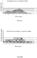
- FIG. 2 depicts a charging system 28 in the process of recharging a battery 26 of the at least one vehicle 18 in idle mode according to the present example.
- the use of autonomous vehicles 18 allows the flexibility of using only the required number of vehicles in duty mode. This allows to decrease the quantity of energy used by the whole fleet of vehicles 18 and to decrease required maintenance on vehicles as they are globally used less than in a fixed driverless automated people mover system. So, when not required in duty mode, a second subset of the fleet of vehicles 18 may be in idle mode. At least one of these vehicles 18, depicted in Figure 2 , uses this opportunity to replenish its battery 26.
- the vehicle 18 in idle mode is therefore connected to the charging station 20, which is itself connected to a controller 22 which manages the one, or more, charging station 20.
- the vehicle 18 in idle mode may be connected to the charging station 20 either by an electric cable 29 such as depicted in Figure 2 , by a catenary, or wirelessly by using an inductive charging technology. If more than one vehicle 18 are in idle mode and if only one charging station 20 is present, the controller 22 may decide to which vehicle 18 in idle mode priority is given in order to recharge its battery 26. It is also possible that all vehicles 18 in idle mode be recharged at once, if a sufficient quantity of recharging stations 20 is provided. Also, it is possible that instead of having one or more charging stations 20 located at a dedicated area outside the main circulating route 14 (i.e.
- a plurality of charging stations 20 be rather located along the circulating route 14, preferably where the vehicles 18 must stop such as at the terminals. The vehicles 18 are then briefly charged.
- Another alternative may be to recharge vehicles 18 along the circulating route 14 with overhead catenaries.
- the charging strategy as detailed below, may remain the same whether the charging stations 20 are located in a dedicated area on the diverging route 16 or whether they are spread along the circulating route 14.
- the drawback of using catenaries however is the increased cost and visual pollution. The most compatible way of recharging with the present method is in a dedicated area.
- the controller 22, connected to the charging station 20, is operative to control a charging rate used by the charging station 20 for charging the respective battery 26 of the at least one vehicle 18 in idle mode.
- This charging rate is determined by the controller 22 based on a duration which is a difference between a time of start of a charging of the vehicle 18 in idle mode and a forecasted time of start of duty mode for that same vehicle 18.
- the forecasted time of start of duty mode is based on the passenger load data and on the passenger capacities of the vehicles 18 in duty mode and in idle mode (which are not necessarily the same). The moment the vehicles 18 in duty mode reach their maximum capacity is the moment the at least one vehicle in idle mode needs to start its duty mode.
- the forecasted time of start of duty mode is the moment a vehicle 18 needs to leave its idle mode to join the subset of the fleet of vehicles 18 already operating in duty mode, based on passenger load data.
- the time of start of charging may be basically as soon as the charging station 20 is ready to charge the battery 26 of a respective one connected vehicle 18 in idle mode.
- the controller 22 may decide not to start charging right away so the time of start of charging may also be a future event.
- the maximum passenger capacity of the at least one vehicle 18 in duty mode may be adjusted for regional preferences, time of year (for example, maximum passenger capacity may be reduced in winter because passenger wear more voluminous clothes), etc. Also, it may be desirable not to reach 100% of the vehicle's theoretical capacity, to provide a more comfortable ride to passengers. Whatever the reason, the maximum capacity of the vehicles 18 in duty mode is a factor considered by the controller 22 when it determines, based on the passenger load as a function of time, the time of start of duty mode for the vehicle 18 in idle mode.
- the controller 22 determines the charging rate for recharging one connected autonomous electric vehicle 18 in idle mode. Knowing that high charging rates may be detrimental to a battery life, the controller 22 tries to use a charging rate that is as low as possible, while not being too low so as to prevent having sufficient time to recharge other vehicles in idle mode as required. For each vehicle 18 in idle mode needing to be recharged, the controller 22 then independently selects the specified lowest charging rate that will both allow maintaining the life of the respective batteries 26 of the vehicles 18 in idle mode while still ensuring maintaining adequate capacity of the vehicles in duty mode. The controller 22 will give priority to maintaining adequate capacity of the subset of vehicle 18 in duty mode.
- the controller 22 will select a higher charging rate which may not be optimum to preserve battery life, but that will ensure sufficient capacity of the subset of vehicles 18 in duty mode.
- the controller 22 is operative to modulate the charging rate inversely proportional to the duration.
- a low charging rate may be comprised between 50 and 100 kW and a high charging rate may be comprised between 100 kW and 400kW, or even higher than 400kW.
- the controller 22 may adjust the charging rate at which the charging station 20 is recharging a battery 26 by increasing or decreasing it if the forecasted passenger load changes, most often unexpectedly. For example, the controller 22 could increase the charging rate at which the charging station 20 is recharging a battery 26 if the forecasted passenger load increases.
- the controller 22 nevertheless always communicates with a battery management system (BMS) 32 to ensure that the determined charging rate never exceeds what the BMS will allow.
- BMS 32 may share information with the controller 22 about battery capacity, state of charge, preferred charging rate and accumulated degradation amongst others.
- the charging system 28 comprises more than one charging station 20.
- the charging system 28 comprises three charging stations 20 charging three vehicles 18 in idle mode.
- the controller 22 controls the charging rates of all three vehicles 18.
- a database 30, containing historical data on the forecasted passenger load, is part of the charging system 28.
- the controller 22 is connected to this database 30 and has access to the stored passenger load data.
- the controller 22 manages the charging of the vehicles 18 in idle mode based on this passenger load data.
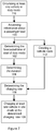
- FIG. 5 shows the steps of a method for managing one or more charging stations 20 that charge the batteries 26 of connected autonomous electric vehicles 18 in idle mode.
- the method comprises the steps of:
- the passenger information may be enclosed in a database to which the controller 22 has access.
- the passenger information may also be determined by analyzing images taken from a camera system 34 installed in strategic areas of the controlled environment 12.
- the cameras of the camera system 34 could be installed at each terminal nearby a door where passengers must exit to embark aboard one of the vehicles 18 in duty mode.
- Each camera relays the information to the camera system 34, which in turn relays the information to an image treatment system capable of determining the number of persons or passengers awaiting to board the next circulating vehicle 18 at a given area 24 (i.e. terminal).
- another option is to access information about passengers aboard incoming flights and to forecast their whereabouts within the controlled environment 12 based on such information.
- load cells may read the load (weight) in the vehicle and determine a percentage of occupancy based on a predetermined weight corresponding to a maximum number of passengers. This information may be related directly to the controller 22 or may be sent to a central computer or cloud 36 to which the controller 22 has access. Alternatively, the passenger load could also be determined using a camera in the vehicles 18 and an adequate software.
- different methods of determining the passenger load may be combined to provide an even more flexible system.
- historical data may be obtained by the controller 22 and updated information from the camera system 34 may also be obtained.
- the controller 22 plans the circulating of the vehicles 18 in duty mode amd the recharging of the vehicles 18 in idle mode, but may still react and adapt according to a change in the forecasted passenger load. For example, a snowstorm could hit the airport and incoming flights are re-routed to a different airport, decreasing the forecasted load of passengers until the situation returns to normal. On the other hand, the same snowstorm could negatively influence the speed at which the vehicles 18 may circulate, thereby possibly requiring additional vehicles 18 in duty mode.
- the method may further comprise:
- the forecasted time of start of duty mode may be a function of the passenger capacity of the vehicle 18 being recharged during idle mode.
- the circulating 110 may further comprise adjusting the quantity of vehicles 18 within the first subset (the vehicles 18 circulating in duty mode) based on the load of passengers. For example, if the load of passengers is detected to increase more than was initially forecasted (for example, the camera system 34 detects more passengers than was forecasted based on historical data), the controller 22 could decide to send a recharged vehicle 18 currently in idle mode into duty mode.
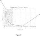
- FIG. 8 depicts an example of the charging rate as a function of duration, in the present case for a battery of 200kWh.
- the charging rate may indeed be calculated as the battery capacity divided by the charging time (which may be equal to the duration in the present case). Because higher charging rates may induce stress in the battery cells, often due to heating, which lead to shortened battery life, charging within a detrimental zone 25 shall be avoided as much as possible.
- the detrimental zone 25 is determined by charging rates higher than 100kW. However, the exact detrimental zone 25 is particular to each battery specifications and shall be adapted in each case.
- the controller 22 therefore tries to avoid charging in the detrimental zone 25 unless absolutely necessary. In the present case, a duration shorter than 2 hours will cause the controller 22 to have to charge at a rate inside the detrimental zone 25. Alternatively, the controller 22 could decide to charge at a charging rate outside the detrimental zone at the expense of having the vehicle 18 being not completely recharged when it enters duty mode. On the other hand, there is no benefit to charging at two small a charging rate either. For example, charging at a rate lower than 50 kW can be avoided as it simply takes too much time for the vehicle to be recharged without benefit on the battery life. Such rates lower than 50kW should therefore be avoided as well. The charging rates lower than 50 kW are highlighted by the low rate zone 27. Consequently, as there is no benefit to charging at such lower rates, the controller 22 charges at a minimum of 50 kW for a maximum of 4 hours.
- Figures 9a and 9b now concurrently referred to, will be used to illustrate a non-limiting example of the present disclosure.
- Figure 9a shows a graph of the forecasted passenger load as a function of time, based on historical data
- Figure 9b shows a graph of the required quantity of vehicles 18 in duty mode as a function of the passenger load shown in Figure 9a .
- the horizontal lines show how many vehicles 18 are required to operate in duty mode based on the passenger load as a function of the time of day. From 4am to 6am, it can be seen that only one vehicle 18 is sufficient to carry passengers. From 6am to 1pm, two vehicles 18 are required in duty mode. From 1pm to 8pm, three vehicles 18 are required in duty mode.
- the controller 22 may plan ahead and recharge the vehicles 18 as required.
- Figure 9b shows such planning of the hours of operation of the vehicles 18.
- one vehicle 18 may circulate during hours before requiring a recharge and that each vehicle 18 is equipped with a battery of 200kWh.
- only one charging station 20 is available. In the present example, no difference is made from which terminal to which terminal the passengers are travelling.
- the vehicles are labelled W, X, Y and Z.
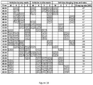
- FIG 10 which is now concurrently referred to, is a timetable showing the operation times (the time in duty mode), the time in idle mode as well as the charging schedule and charging rates for each vehicles W, X, Y and Z.
- the duration is represented by the length of the charging times. For example, when the charging time of vehicle W extends from 4:00 to 7:00, the charging time is 3 hours.
- the controller 22 tries to charge the vehicles 18 at a lower charging rate whenever possible. Most of the times, the vehicles 18 have 3 hours to recharge, so the charging rate is 67 kW.
- the controller 22 schedules the recharging of some vehicles at a higher charging rate, for example 100kW (vehicles W and Z). From 6:00pm to 7:00pm, the controller 22 instructs the charging station 20 to charge vehicle W during one hour at 200kW.
- the controller 22 may have to react to unplanned increase in passenger loads. This is shown in Figure 11 , now concurrently referred to, where a passenger load higher than forecasted by historical data is shown between 6:00am and noon. Figure 12 , showing a timetable adjusted to suit the unplanned increased passenger load shown in Figure 11 .
- the raise in passenger load is first detected at 6:00am, but it still does not require to send an additional vehicle 18 in duty mode.
- vehicles X and Y are in duty mode and vehicles W and Z are in idle mode. Vehicle W is not completely charged, but will be by 7:00am. Vehicle Z is not yet charged, so it is not available yet for duty mode.
- the controller 22 decides to send the vehicle W in duty mode at 7:00.
- the controller 22 orders vehicle W to leave duty mode and enter idle mode upon detecting a lower passenger load at 11:00am. During that time, controller 22 must adjust the charging rate of vehicle X at 200kW because it will have to leave its place at the charging station 20 to vehicle W when it briefly re-enters idle mode for one hour at 11:00am. Then at 11:00am, the controller 22 orders the charging station 20 to charge vehicle W at 200kW also for one hour since it has to re-enter duty mode at noon. On the other hand, at noon, only vehicle Y is in idle mode until 16:00, so the controller 22 may order the charging station 20 to charge vehicle Y at a lower charging rate of 50kW.
Landscapes
- Engineering & Computer Science (AREA)
- Power Engineering (AREA)
- Mechanical Engineering (AREA)
- Business, Economics & Management (AREA)
- Transportation (AREA)
- Human Resources & Organizations (AREA)
- Life Sciences & Earth Sciences (AREA)
- Sustainable Development (AREA)
- Sustainable Energy (AREA)
- Strategic Management (AREA)
- Entrepreneurship & Innovation (AREA)
- Economics (AREA)
- Educational Administration (AREA)
- Tourism & Hospitality (AREA)
- Game Theory and Decision Science (AREA)
- Aviation & Aerospace Engineering (AREA)
- Marketing (AREA)
- Operations Research (AREA)
- Quality & Reliability (AREA)
- Development Economics (AREA)
- Physics & Mathematics (AREA)
- General Business, Economics & Management (AREA)
- General Physics & Mathematics (AREA)
- Theoretical Computer Science (AREA)
- Charge And Discharge Circuits For Batteries Or The Like (AREA)
- Secondary Cells (AREA)
Claims (14)
- Verfahren zum Verwalten einer Ladestation (20) zum Laden einer Batterie (26) eines verbundenen autonomen Elektrofahrzeugs (18) zum Befördern von Passagieren in einer kontrollierten Umgebung, wobei das Verfahren Folgendes umfasst:Zugreifen auf Informationen über eine Passagierlast in Abhängigkeit von Zeit;Bestimmen einer prognostizierten Zeit eines Starts eines Dienstmodus basierend auf der Passagierlast;Bestimmen einer Dauer zwischen einer Zeit des Starts des Ladens der Batterie (26) und der prognostizierten Zeit des Starts des Dienstmodus des verbundenen autonomen Elektrofahrzeugs (18);Bestimmen einer Laderate, wobei die Laderate eine Funktion der Dauer ist; undLaden der Batterie (26) des verbundenen autonomen Elektrofahrzeugs (18) mit der bestimmten Laderate, wobei die Batterie (26) nicht mit einer hohen Laderate geladen wird, wenn dies nicht erforderlich ist, um die Lebenserwartung der Batterie zu verlängern, dadurch gekennzeichnet, dass die Zeit des Starts des Dienstmodus des verbundenen autonomen Elektrofahrzeugs eine Funktion einer Fahrzeugpassagierkapazität ist.
- Verfahren nach Anspruch 1, wobei die Passagierlast auf historischen Daten basiert.
- Verfahren nach einem der vorhergehenden Ansprüche, das ferner das Bestimmen der Passagierlast basierend auf einer Bildanalyse von Passagieren umfasst, die in einem Flughafen zirkulieren.
- Verfahren nach einem der vorhergehenden Ansprüche, das ferner das Bestimmen der Passagierlast basierend auf Passagierinformationen von Passagieren umfasst, die sich an Bord ankommender Flüge befinden.
- Verfahren nach Anspruch 4, wobei das Bestimmen der Passagierlast ein Auswählen der Passagierinformationen aus der Gruppe umfasst, die aus Folgendem besteht:
Flugnummer, Identifizierung des Ankunftsgates, Reiseziel, Anschlussflugnummer, Abfluggate, Anzahl von Passagieren und Anzahl von Flugpersonal. - Verfahren nach einem der vorhergehenden Ansprüche, wobei das Laden der Batterie ein Verwenden einer Laderate umfasst, die proportional zu der Passagierlast ist.
- Verfahren nach einem der vorhergehenden Ansprüche, wobei das Laden der Batterie das Verwenden einer Laderate umfasst, die umgekehrt proportional zur Dauer ist.
- System (28) zum Befördern von Passagieren innerhalb einer kontrollierten Umgebung, wobei das System Folgendes umfasst:
eine Flotte von autonomen Elektrofahrzeugen (18) zum Befördern von Passagieren, wobei jedes Fahrzeug (18) der Flotte von autonomen Elektrofahrzeugen eine Batterie (26) aufweist, wobei die Flotte Folgendes aufweist:wenigstens ein Fahrzeug (18) in einem Dienstmodus, wobei das wenigstens eine Fahrzeug im Dienstmodus betriebsfähig ist, um Passagiere von einem ersten Bereich zu einem zweiten Bereich der kontrollierten Umgebung zu befördern;wenigstens ein Fahrzeug (18) in einem Leerlaufmodus; undwobei das wenigstens eine Fahrzeug (18) im Leerlaufmodus mit einer Ladestation (20) zum Laden seiner Batterie (26) mit einer variablen Laderate unter der Steuerung einer Steuervorrichtung (22) verbunden ist, die mit der Ladestation (20) verbunden ist, wobei die Steuervorrichtung (22) betriebsfähig ist, um eine Zeit des Starts des Dienstmodus des wenigstens einen Fahrzeugs (18) in dem Leerlaufmodus in Abhängigkeit von einer Fahrzeugpassagierkapazität zu bestimmen, wobei die Batterie nicht mit einer hohen Laderate geladen wird, wenn dies nicht erforderlich ist, um die Lebenserwartung der Batterie zu verlängern. - System (28) nach Anspruch 8, wobei die Steuervorrichtung (22) betriebsfähig ist, um eine Dauer zwischen einer Zeit des Starts des Ladens des Fahrzeugs (18) und einer prognostizierten Zeit des Starts des Dienstmodus des Fahrzeugs (18) basierend auf einer prognostizierten Last von Passagieren zu bestimmen, die von dem ersten Bereich zu dem zweiten Bereich der kontrollierten Umgebung in Abhängigkeit von Zeit befördert werden soll.
- System (28) nach einem der Ansprüche 8 bis 9, wobei:die Ladestation (20) angepasst ist, um die Batterie (26) mit einer variablen Laderate zu laden; unddie Steuervorrichtung (22) betriebsfähig ist, um die Laderate der Batterie (26) basierend auf einer Dauer zwischen einer Zeit des Starts des Ladens der Batterie (26) und der bestimmten Zeit des Starts des Dienstmodus des wenigstens einen Fahrzeugs in dem Leerlaufmodus zu bestimmen und modulieren, wobei die Dauer durch die Steuervorrichtung basierend auf einer prognostizierten Passagierlast in Abhängigkeit von Zeit bestimmt wird.
- System (28) nach einem der Ansprüche 8 bis 10, wobei die Steuervorrichtung (22) für Folgendes betriebsfähig ist:
Erhöhen der Laderate, wenn sich die prognostizierte Passagierlast erhöht, und/oder Modulieren der Laderate umgekehrt proportional zu der Dauer. - System (28) nach einem der Ansprüche 8 bis 11, das ferner eine Datenbank umfasst, die historische Daten über die prognostizierte Passagierlast enthält.
- System (28) nach einem der Ansprüche 8 bis 12, das ferner ein Bildanalysesystem umfasst, wobei das Bildanalysesystem mit der Steuervorrichtung (22) und mit einem Kamerasystem (34) verbunden ist, wobei das Bildanalysesystem betriebsfähig ist, um die prognostizierte Passagierlast basierend auf einer Bildanalyse von Passagieren zu bestimmen, die in einem Flughafen (12) zirkulieren.
- System nach einem der Ansprüche 8 bis 13, wobei die Steuervorrichtung (22) wirkverbunden ist, um Informationen über Reisende zu empfangen, die sich an Bord ankommender Flüge befinden, und um die prognostizierte Passagierlast basierend auf den Informationen zu bestimmen.
Priority Applications (1)
| Application Number | Priority Date | Filing Date | Title |
|---|---|---|---|
| PL19020721T PL3672017T3 (pl) | 2018-12-20 | 2019-12-20 | System i sposób modulacji prędkości ładowania dla ładowania akumulatora pojazdu w funkcji oczekiwanego obciążenia pasażerami |
Applications Claiming Priority (1)
| Application Number | Priority Date | Filing Date | Title |
|---|---|---|---|
| US201862782516P | 2018-12-20 | 2018-12-20 |
Publications (2)
| Publication Number | Publication Date |
|---|---|
| EP3672017A1 EP3672017A1 (de) | 2020-06-24 |
| EP3672017B1 true EP3672017B1 (de) | 2021-09-01 |
Family
ID=69143374
Family Applications (1)
| Application Number | Title | Priority Date | Filing Date |
|---|---|---|---|
| EP19020721.7A Active EP3672017B1 (de) | 2018-12-20 | 2019-12-20 | System und verfahren zum modulieren einer laderate zum laden einer batterie eines fahrzeugs in abhängigkeit von einer erwarteten fahrgastlast |
Country Status (4)
| Country | Link |
|---|---|
| US (1) | US11247579B2 (de) |
| EP (1) | EP3672017B1 (de) |
| CN (1) | CN111347912B (de) |
| PL (1) | PL3672017T3 (de) |
Families Citing this family (2)
| Publication number | Priority date | Publication date | Assignee | Title |
|---|---|---|---|---|
| JP2021012566A (ja) * | 2019-07-08 | 2021-02-04 | トヨタ自動車株式会社 | 充電マネージメントシステム |
| CN118569608B (zh) * | 2024-08-01 | 2024-11-29 | 北京市运输事业发展中心 | 一种用于摆渡车的动态智慧管理方法 |
Family Cites Families (26)
| Publication number | Priority date | Publication date | Assignee | Title |
|---|---|---|---|---|
| JP3536703B2 (ja) | 1999-02-09 | 2004-06-14 | 株式会社日立製作所 | ハイブリッド車両の制御方法、ハイブリッド車両の制御装置およびハイブリッド車両 |
| US7620482B2 (en) * | 2003-03-05 | 2009-11-17 | Dc Interconnect Inc. | Electricity market-oriented dc-segmentation design and optimal scheduling for electrical power transmission |
| DE102005024403A1 (de) | 2005-05-27 | 2007-01-18 | Güttler, Gerhard, Prof. Dr. | Verfahren und Vorrichtung zum Einsparen von Energie in einem Fahrzeug |
| US8212532B2 (en) * | 2008-07-24 | 2012-07-03 | General Electric Company | Method and system for control of a vehicle energy storage device |
| US20110016063A1 (en) * | 2009-07-17 | 2011-01-20 | Gridpoint, Inc. | System and methods for smart charging techniques |
| JP5214764B2 (ja) * | 2011-03-25 | 2013-06-19 | 株式会社東芝 | 電気自動車充電スケジューリングシステム |
| US9718371B2 (en) * | 2011-06-30 | 2017-08-01 | International Business Machines Corporation | Recharging of battery electric vehicles on a smart electrical grid system |
| US9000722B2 (en) * | 2011-07-01 | 2015-04-07 | Honda Motor Co., Ltd. | Electric vehicle charging strategy |
| CN103875148B (zh) * | 2011-10-07 | 2017-07-11 | 丰田自动车株式会社 | 车辆的充电系统和车辆的充电方法 |
| JP5739788B2 (ja) * | 2011-11-15 | 2015-06-24 | 株式会社東芝 | 充放電計画立案システムおよび充放電計画立案方法 |
| US9013143B2 (en) * | 2012-03-09 | 2015-04-21 | GM Global Technology Operations LLC | Method for charging a plug-in electric vehicle |
| EP2849312A4 (de) * | 2012-04-12 | 2016-06-01 | Hitachi Ltd | Fahrzeugsteuerungssystem |
| GB2507388B (en) * | 2012-09-28 | 2015-06-03 | Hitachi Ltd | Train operation management system and train operation management method |
| DE102013201563B4 (de) | 2013-01-30 | 2025-02-06 | Bayerische Motoren Werke Aktiengesellschaft | Personalisierung der Energieversorgung und des Energiemanagements in Fahrzeugen |
| EP2979240A1 (de) * | 2013-03-27 | 2016-02-03 | Udviklingsselskabet Af 2014 ApS | Verfahren und handgepäckwagen zur erleichterung eines passagierflusses in einem flughafenabfertigungsgebäude |
| US9457682B2 (en) * | 2013-08-30 | 2016-10-04 | GM Global Technology Operations LLC | Method for predicting charging process duration |
| US10703219B2 (en) * | 2013-10-04 | 2020-07-07 | Ford Global Technologies, Llc | Vehicle battery charge setpoint control |
| JP6301730B2 (ja) * | 2013-10-04 | 2018-03-28 | 株式会社東芝 | 電動車両の運行管理装置及び運行計画立案方法 |
| KR101798514B1 (ko) * | 2015-11-09 | 2017-11-16 | 현대자동차주식회사 | 차량 및 그 충전 제어방법 |
| CN113844313B (zh) * | 2016-08-23 | 2024-02-20 | 柏思科技有限公司 | 用于将电力分配到多个负载的方法和系统 |
| US10099569B2 (en) * | 2016-09-29 | 2018-10-16 | GM Global Technology Operations LLC | Adaptive system and method for optimizing a fleet of plug-in vehicles |
| US9955428B1 (en) * | 2016-10-24 | 2018-04-24 | International Business Machines Corporation | Optimizing scheduled charging of battery enabled devices based on a predicted battery consumption factor for an area |
| US10300808B2 (en) * | 2017-04-20 | 2019-05-28 | Nio Usa, Inc. | Preconditioned charging using an autonomous vehicle |
| US20180329374A1 (en) * | 2017-05-15 | 2018-11-15 | Microsoft Technology Licensing, Llc | Systems and methods for optimizing an energy storage device charging schedule |
| WO2018213453A1 (en) * | 2017-05-16 | 2018-11-22 | Hubbell Incorporated | Automated electric vehicle charging |
| CN107069753B (zh) * | 2017-05-16 | 2019-07-12 | 电子科技大学 | 一种考虑行为随机性的电动汽车参与电网调压调度方法 |
-
2019
- 2019-12-20 CN CN201911325416.XA patent/CN111347912B/zh active Active
- 2019-12-20 US US16/722,035 patent/US11247579B2/en active Active
- 2019-12-20 PL PL19020721T patent/PL3672017T3/pl unknown
- 2019-12-20 EP EP19020721.7A patent/EP3672017B1/de active Active
Also Published As
| Publication number | Publication date |
|---|---|
| EP3672017A1 (de) | 2020-06-24 |
| CN111347912A (zh) | 2020-06-30 |
| US20200198491A1 (en) | 2020-06-25 |
| CN111347912B (zh) | 2023-09-05 |
| PL3672017T3 (pl) | 2022-01-24 |
| US11247579B2 (en) | 2022-02-15 |
Similar Documents
| Publication | Publication Date | Title |
|---|---|---|
| US12447850B2 (en) | Dispatch-based charging for electric vehicle fleet | |
| US11498440B2 (en) | Vehicle traffic and charge management system using autonomous cluster networks of vehicle charging stations | |
| US10549645B2 (en) | Smart-charging apparatus for use with electric-vehicle-sharing stations | |
| US11571974B2 (en) | Systems and methods for mobile charging of electric vehicles | |
| US6810817B1 (en) | Intelligent transport system | |
| US10293699B2 (en) | Smart-charging apparatus for use with electric-vehicle-sharing stations | |
| JP2019082753A (ja) | 配車システム及び配車方法 | |
| US20230406130A1 (en) | Automated charging process for a motor vehicle | |
| CN116572788A (zh) | 电动化车辆与充电挂车之间电力流优先级排序系统和方法 | |
| EP3672017B1 (de) | System und verfahren zum modulieren einer laderate zum laden einer batterie eines fahrzeugs in abhängigkeit von einer erwarteten fahrgastlast | |
| CN116252646A (zh) | 控制电动化车辆与充电挂车之间的电力流的系统和方法 | |
| US20230278453A1 (en) | Method for controlling a charging infrastructure | |
| US20220189328A1 (en) | Podport and Associated Podways for Unmanned Arial Vehicles | |
| US20250128632A1 (en) | Charging Strategies for Electric Vehicles | |
| US20240221103A1 (en) | Strategic Opportunity Charging for On-route Electric Vehicles | |
| US12485789B2 (en) | Strategic opportunity charging for on-route electric vehicles | |
| US20240217387A1 (en) | Strategic Opportunity Charging for On-Route Electric Vehicles | |
| US20250050777A1 (en) | Strategic Opportunity Charging for On-Route Electric Vehicles | |
| Khalid et al. | Toward autonomous valet parking: A broader perspective | |
| EP4642668A1 (de) | Strategische gelegenheitsladung für elektrofahrzeuge auf der route | |
| WO2024144824A1 (en) | Strategic opportunity charging for on-route electric vehicles | |
| WO2025014372A1 (en) | Management of electrical power using a vehicle battery | |
| WO2025049005A1 (en) | System and method for scheduling and pacing trains |
Legal Events
| Date | Code | Title | Description |
|---|---|---|---|
| PUAI | Public reference made under article 153(3) epc to a published international application that has entered the european phase |
Free format text: ORIGINAL CODE: 0009012 |
|
| STAA | Information on the status of an ep patent application or granted ep patent |
Free format text: STATUS: REQUEST FOR EXAMINATION WAS MADE |
|
| 17P | Request for examination filed |
Effective date: 20200116 |
|
| AK | Designated contracting states |
Kind code of ref document: A1 Designated state(s): AL AT BE BG CH CY CZ DE DK EE ES FI FR GB GR HR HU IE IS IT LI LT LU LV MC MK MT NL NO PL PT RO RS SE SI SK SM TR |
|
| AX | Request for extension of the european patent |
Extension state: BA ME |
|
| RIN1 | Information on inventor provided before grant (corrected) |
Inventor name: HOULE, MARTIN |
|
| RBV | Designated contracting states (corrected) |
Designated state(s): AL AT BE BG CH CY CZ DE DK EE ES FI FR GB GR HR HU IE IS IT LI LT LU LV MC MK MT NL NO PL PT RO RS SE SI SK SM TR |
|
| GRAP | Despatch of communication of intention to grant a patent |
Free format text: ORIGINAL CODE: EPIDOSNIGR1 |
|
| STAA | Information on the status of an ep patent application or granted ep patent |
Free format text: STATUS: GRANT OF PATENT IS INTENDED |
|
| INTG | Intention to grant announced |
Effective date: 20210316 |
|
| GRAS | Grant fee paid |
Free format text: ORIGINAL CODE: EPIDOSNIGR3 |
|
| GRAA | (expected) grant |
Free format text: ORIGINAL CODE: 0009210 |
|
| STAA | Information on the status of an ep patent application or granted ep patent |
Free format text: STATUS: THE PATENT HAS BEEN GRANTED |
|
| AK | Designated contracting states |
Kind code of ref document: B1 Designated state(s): AL AT BE BG CH CY CZ DE DK EE ES FI FR GB GR HR HU IE IS IT LI LT LU LV MC MK MT NL NO PL PT RO RS SE SI SK SM TR |
|
| REG | Reference to a national code |
Ref country code: GB Ref legal event code: FG4D |
|
| REG | Reference to a national code |
Ref country code: CH Ref legal event code: EP Ref country code: AT Ref legal event code: REF Ref document number: 1427239 Country of ref document: AT Kind code of ref document: T Effective date: 20210915 |
|
| REG | Reference to a national code |
Ref country code: DE Ref legal event code: R096 Ref document number: 602019007223 Country of ref document: DE |
|
| REG | Reference to a national code |
Ref country code: IE Ref legal event code: FG4D |
|
| REG | Reference to a national code |
Ref country code: SE Ref legal event code: TRGR |
|
| REG | Reference to a national code |
Ref country code: NL Ref legal event code: FP |
|
| REG | Reference to a national code |
Ref country code: LT Ref legal event code: MG9D |
|
| PG25 | Lapsed in a contracting state [announced via postgrant information from national office to epo] |
Ref country code: FI Free format text: LAPSE BECAUSE OF FAILURE TO SUBMIT A TRANSLATION OF THE DESCRIPTION OR TO PAY THE FEE WITHIN THE PRESCRIBED TIME-LIMIT Effective date: 20210901 Ref country code: ES Free format text: LAPSE BECAUSE OF FAILURE TO SUBMIT A TRANSLATION OF THE DESCRIPTION OR TO PAY THE FEE WITHIN THE PRESCRIBED TIME-LIMIT Effective date: 20210901 Ref country code: RS Free format text: LAPSE BECAUSE OF FAILURE TO SUBMIT A TRANSLATION OF THE DESCRIPTION OR TO PAY THE FEE WITHIN THE PRESCRIBED TIME-LIMIT Effective date: 20210901 Ref country code: HR Free format text: LAPSE BECAUSE OF FAILURE TO SUBMIT A TRANSLATION OF THE DESCRIPTION OR TO PAY THE FEE WITHIN THE PRESCRIBED TIME-LIMIT Effective date: 20210901 Ref country code: NO Free format text: LAPSE BECAUSE OF FAILURE TO SUBMIT A TRANSLATION OF THE DESCRIPTION OR TO PAY THE FEE WITHIN THE PRESCRIBED TIME-LIMIT Effective date: 20211201 Ref country code: BG Free format text: LAPSE BECAUSE OF FAILURE TO SUBMIT A TRANSLATION OF THE DESCRIPTION OR TO PAY THE FEE WITHIN THE PRESCRIBED TIME-LIMIT Effective date: 20211201 Ref country code: LT Free format text: LAPSE BECAUSE OF FAILURE TO SUBMIT A TRANSLATION OF THE DESCRIPTION OR TO PAY THE FEE WITHIN THE PRESCRIBED TIME-LIMIT Effective date: 20210901 |
|
| REG | Reference to a national code |
Ref country code: AT Ref legal event code: MK05 Ref document number: 1427239 Country of ref document: AT Kind code of ref document: T Effective date: 20210901 |
|
| PG25 | Lapsed in a contracting state [announced via postgrant information from national office to epo] |
Ref country code: LV Free format text: LAPSE BECAUSE OF FAILURE TO SUBMIT A TRANSLATION OF THE DESCRIPTION OR TO PAY THE FEE WITHIN THE PRESCRIBED TIME-LIMIT Effective date: 20210901 Ref country code: GR Free format text: LAPSE BECAUSE OF FAILURE TO SUBMIT A TRANSLATION OF THE DESCRIPTION OR TO PAY THE FEE WITHIN THE PRESCRIBED TIME-LIMIT Effective date: 20211202 |
|
| PG25 | Lapsed in a contracting state [announced via postgrant information from national office to epo] |
Ref country code: AT Free format text: LAPSE BECAUSE OF FAILURE TO SUBMIT A TRANSLATION OF THE DESCRIPTION OR TO PAY THE FEE WITHIN THE PRESCRIBED TIME-LIMIT Effective date: 20210901 |
|
| PG25 | Lapsed in a contracting state [announced via postgrant information from national office to epo] |
Ref country code: IS Free format text: LAPSE BECAUSE OF FAILURE TO SUBMIT A TRANSLATION OF THE DESCRIPTION OR TO PAY THE FEE WITHIN THE PRESCRIBED TIME-LIMIT Effective date: 20220101 Ref country code: SM Free format text: LAPSE BECAUSE OF FAILURE TO SUBMIT A TRANSLATION OF THE DESCRIPTION OR TO PAY THE FEE WITHIN THE PRESCRIBED TIME-LIMIT Effective date: 20210901 Ref country code: SK Free format text: LAPSE BECAUSE OF FAILURE TO SUBMIT A TRANSLATION OF THE DESCRIPTION OR TO PAY THE FEE WITHIN THE PRESCRIBED TIME-LIMIT Effective date: 20210901 Ref country code: RO Free format text: LAPSE BECAUSE OF FAILURE TO SUBMIT A TRANSLATION OF THE DESCRIPTION OR TO PAY THE FEE WITHIN THE PRESCRIBED TIME-LIMIT Effective date: 20210901 Ref country code: PT Free format text: LAPSE BECAUSE OF FAILURE TO SUBMIT A TRANSLATION OF THE DESCRIPTION OR TO PAY THE FEE WITHIN THE PRESCRIBED TIME-LIMIT Effective date: 20220103 Ref country code: EE Free format text: LAPSE BECAUSE OF FAILURE TO SUBMIT A TRANSLATION OF THE DESCRIPTION OR TO PAY THE FEE WITHIN THE PRESCRIBED TIME-LIMIT Effective date: 20210901 Ref country code: CZ Free format text: LAPSE BECAUSE OF FAILURE TO SUBMIT A TRANSLATION OF THE DESCRIPTION OR TO PAY THE FEE WITHIN THE PRESCRIBED TIME-LIMIT Effective date: 20210901 Ref country code: AL Free format text: LAPSE BECAUSE OF FAILURE TO SUBMIT A TRANSLATION OF THE DESCRIPTION OR TO PAY THE FEE WITHIN THE PRESCRIBED TIME-LIMIT Effective date: 20210901 |
|
| REG | Reference to a national code |
Ref country code: DE Ref legal event code: R097 Ref document number: 602019007223 Country of ref document: DE |
|
| PLBE | No opposition filed within time limit |
Free format text: ORIGINAL CODE: 0009261 |
|
| STAA | Information on the status of an ep patent application or granted ep patent |
Free format text: STATUS: NO OPPOSITION FILED WITHIN TIME LIMIT |
|
| PG25 | Lapsed in a contracting state [announced via postgrant information from national office to epo] |
Ref country code: MC Free format text: LAPSE BECAUSE OF FAILURE TO SUBMIT A TRANSLATION OF THE DESCRIPTION OR TO PAY THE FEE WITHIN THE PRESCRIBED TIME-LIMIT Effective date: 20210901 Ref country code: DK Free format text: LAPSE BECAUSE OF FAILURE TO SUBMIT A TRANSLATION OF THE DESCRIPTION OR TO PAY THE FEE WITHIN THE PRESCRIBED TIME-LIMIT Effective date: 20210901 |
|
| 26N | No opposition filed |
Effective date: 20220602 |
|
| PG25 | Lapsed in a contracting state [announced via postgrant information from national office to epo] |
Ref country code: SI Free format text: LAPSE BECAUSE OF FAILURE TO SUBMIT A TRANSLATION OF THE DESCRIPTION OR TO PAY THE FEE WITHIN THE PRESCRIBED TIME-LIMIT Effective date: 20210901 |
|
| REG | Reference to a national code |
Ref country code: BE Ref legal event code: MM Effective date: 20211231 |
|
| PG25 | Lapsed in a contracting state [announced via postgrant information from national office to epo] |
Ref country code: LU Free format text: LAPSE BECAUSE OF NON-PAYMENT OF DUE FEES Effective date: 20211220 Ref country code: IE Free format text: LAPSE BECAUSE OF NON-PAYMENT OF DUE FEES Effective date: 20211220 |
|
| PG25 | Lapsed in a contracting state [announced via postgrant information from national office to epo] |
Ref country code: BE Free format text: LAPSE BECAUSE OF NON-PAYMENT OF DUE FEES Effective date: 20211231 |
|
| PG25 | Lapsed in a contracting state [announced via postgrant information from national office to epo] |
Ref country code: CY Free format text: LAPSE BECAUSE OF FAILURE TO SUBMIT A TRANSLATION OF THE DESCRIPTION OR TO PAY THE FEE WITHIN THE PRESCRIBED TIME-LIMIT Effective date: 20210901 |
|
| PG25 | Lapsed in a contracting state [announced via postgrant information from national office to epo] |
Ref country code: HU Free format text: LAPSE BECAUSE OF FAILURE TO SUBMIT A TRANSLATION OF THE DESCRIPTION OR TO PAY THE FEE WITHIN THE PRESCRIBED TIME-LIMIT; INVALID AB INITIO Effective date: 20191220 |
|
| P01 | Opt-out of the competence of the unified patent court (upc) registered |
Effective date: 20230822 |
|
| PG25 | Lapsed in a contracting state [announced via postgrant information from national office to epo] |
Ref country code: MK Free format text: LAPSE BECAUSE OF FAILURE TO SUBMIT A TRANSLATION OF THE DESCRIPTION OR TO PAY THE FEE WITHIN THE PRESCRIBED TIME-LIMIT Effective date: 20210901 |
|
| PG25 | Lapsed in a contracting state [announced via postgrant information from national office to epo] |
Ref country code: MT Free format text: LAPSE BECAUSE OF FAILURE TO SUBMIT A TRANSLATION OF THE DESCRIPTION OR TO PAY THE FEE WITHIN THE PRESCRIBED TIME-LIMIT Effective date: 20210901 |
|
| PGFP | Annual fee paid to national office [announced via postgrant information from national office to epo] |
Ref country code: DE Payment date: 20241210 Year of fee payment: 6 |
|
| PGFP | Annual fee paid to national office [announced via postgrant information from national office to epo] |
Ref country code: PL Payment date: 20241213 Year of fee payment: 6 Ref country code: NL Payment date: 20241219 Year of fee payment: 6 |
|
| PGFP | Annual fee paid to national office [announced via postgrant information from national office to epo] |
Ref country code: GB Payment date: 20241226 Year of fee payment: 6 |
|
| PGFP | Annual fee paid to national office [announced via postgrant information from national office to epo] |
Ref country code: FR Payment date: 20241224 Year of fee payment: 6 |
|
| PGFP | Annual fee paid to national office [announced via postgrant information from national office to epo] |
Ref country code: SE Payment date: 20241219 Year of fee payment: 6 |
|
| PGFP | Annual fee paid to national office [announced via postgrant information from national office to epo] |
Ref country code: CH Payment date: 20250101 Year of fee payment: 6 |
|
| PGFP | Annual fee paid to national office [announced via postgrant information from national office to epo] |
Ref country code: IT Payment date: 20241227 Year of fee payment: 6 |