EP3672016B1 - Charging management circuit, terminal and charging method - Google Patents
Charging management circuit, terminal and charging method Download PDFInfo
- Publication number
- EP3672016B1 EP3672016B1 EP18932974.1A EP18932974A EP3672016B1 EP 3672016 B1 EP3672016 B1 EP 3672016B1 EP 18932974 A EP18932974 A EP 18932974A EP 3672016 B1 EP3672016 B1 EP 3672016B1
- Authority
- EP
- European Patent Office
- Prior art keywords
- charging
- cell
- voltage
- constant current
- current charging
- Prior art date
- Legal status (The legal status is an assumption and is not a legal conclusion. Google has not performed a legal analysis and makes no representation as to the accuracy of the status listed.)
- Active
Links
Images
Classifications
-
- H—ELECTRICITY
- H01—ELECTRIC ELEMENTS
- H01M—PROCESSES OR MEANS, e.g. BATTERIES, FOR THE DIRECT CONVERSION OF CHEMICAL ENERGY INTO ELECTRICAL ENERGY
- H01M10/00—Secondary cells; Manufacture thereof
- H01M10/42—Methods or arrangements for servicing or maintenance of secondary cells or secondary half-cells
- H01M10/44—Methods for charging or discharging
- H01M10/446—Initial charging measures
-
- H—ELECTRICITY
- H02—GENERATION; CONVERSION OR DISTRIBUTION OF ELECTRIC POWER
- H02J—ELECTRIC POWER NETWORKS; CIRCUIT ARRANGEMENTS OR SYSTEMS FOR SUPPLYING OR DISTRIBUTING ELECTRIC POWER; SYSTEMS FOR STORING ELECTRIC ENERGY
- H02J7/00—Circuit arrangements for charging or discharging batteries or for supplying loads from batteries
- H02J7/90—Regulation of charging or discharging current or voltage
- H02J7/96—Regulation of charging or discharging current or voltage in response to battery voltage
-
- H—ELECTRICITY
- H01—ELECTRIC ELEMENTS
- H01M—PROCESSES OR MEANS, e.g. BATTERIES, FOR THE DIRECT CONVERSION OF CHEMICAL ENERGY INTO ELECTRICAL ENERGY
- H01M10/00—Secondary cells; Manufacture thereof
- H01M10/42—Methods or arrangements for servicing or maintenance of secondary cells or secondary half-cells
- H01M10/44—Methods for charging or discharging
-
- H—ELECTRICITY
- H02—GENERATION; CONVERSION OR DISTRIBUTION OF ELECTRIC POWER
- H02J—ELECTRIC POWER NETWORKS; CIRCUIT ARRANGEMENTS OR SYSTEMS FOR SUPPLYING OR DISTRIBUTING ELECTRIC POWER; SYSTEMS FOR STORING ELECTRIC ENERGY
- H02J7/00—Circuit arrangements for charging or discharging batteries or for supplying loads from batteries
- H02J7/80—Circuit arrangements for charging or discharging batteries or for supplying loads from batteries including monitoring or indicating arrangements
-
- H—ELECTRICITY
- H02—GENERATION; CONVERSION OR DISTRIBUTION OF ELECTRIC POWER
- H02J—ELECTRIC POWER NETWORKS; CIRCUIT ARRANGEMENTS OR SYSTEMS FOR SUPPLYING OR DISTRIBUTING ELECTRIC POWER; SYSTEMS FOR STORING ELECTRIC ENERGY
- H02J7/00—Circuit arrangements for charging or discharging batteries or for supplying loads from batteries
- H02J7/90—Regulation of charging or discharging current or voltage
- H02J7/92—Regulation of charging or discharging current or voltage with prioritisation of loads or sources
-
- H—ELECTRICITY
- H02—GENERATION; CONVERSION OR DISTRIBUTION OF ELECTRIC POWER
- H02J—ELECTRIC POWER NETWORKS; CIRCUIT ARRANGEMENTS OR SYSTEMS FOR SUPPLYING OR DISTRIBUTING ELECTRIC POWER; SYSTEMS FOR STORING ELECTRIC ENERGY
- H02J7/00—Circuit arrangements for charging or discharging batteries or for supplying loads from batteries
- H02J7/90—Regulation of charging or discharging current or voltage
- H02J7/94—Regulation of charging or discharging current or voltage in response to battery current
-
- H—ELECTRICITY
- H02—GENERATION; CONVERSION OR DISTRIBUTION OF ELECTRIC POWER
- H02J—ELECTRIC POWER NETWORKS; CIRCUIT ARRANGEMENTS OR SYSTEMS FOR SUPPLYING OR DISTRIBUTING ELECTRIC POWER; SYSTEMS FOR STORING ELECTRIC ENERGY
- H02J7/00—Circuit arrangements for charging or discharging batteries or for supplying loads from batteries
- H02J7/865—Battery or charger load switching, e.g. concurrent charging and load supply
-
- H—ELECTRICITY
- H02—GENERATION; CONVERSION OR DISTRIBUTION OF ELECTRIC POWER
- H02J—ELECTRIC POWER NETWORKS; CIRCUIT ARRANGEMENTS OR SYSTEMS FOR SUPPLYING OR DISTRIBUTING ELECTRIC POWER; SYSTEMS FOR STORING ELECTRIC ENERGY
- H02J7/00—Circuit arrangements for charging or discharging batteries or for supplying loads from batteries
- H02J7/90—Regulation of charging or discharging current or voltage
- H02J7/971—Regulation of charging or discharging current or voltage the charge cycle being controlled or terminated in response to non-electric parameters
- H02J7/975—Regulation of charging or discharging current or voltage the charge cycle being controlled or terminated in response to non-electric parameters in response to temperature
Definitions
- the present disclosure relates to a charging technology field, and more particularly, to a charging management circuit, a terminal and a charging method.
- a constant current and constant voltage mode is generally adopted to charge a cell. That is, the cell is first charged in a constant current mode, and when a voltage across both ends of the cell reaches a constant current charging cut-off voltage, a constant voltage charging stage is started. And in the constant voltage charging stage, the cell is charged with a high voltage, and the charging current of the cell is gradually reduced as the charging process proceeds. The charging is finished when the charging current of the cell reaches a constant voltage charging cut-off current.
- the constant voltage charging stage normally takes a long time, so that a charging speed of the cell is slow.
- Document US 2014/184173 A relates to a method and apparatus for controlling a composite battery charger including a switching regulator and a linear charger charging a battery connected to it, whereby the switching regulator provides the supply voltage for the linear charger and Device Circuits.
- the control method and circuit fully turns on the pass device of the linear charger in a constant current operating mode and the switching regulator is controlled to maintain a constant charge current through the pass device while also supplying device current to the Device Circuits.
- the device current may vary.
- the method and circuit limits the dissipation of the pass device of the linear charger by reducing the supply voltage as a function of the charge current in the CC/CV transition region of the battery charger and by reducing the charge current as a function of the battery voltage if the battery voltage is below a predetermined value related to a predetermined minimum supply voltage value.
- Document CN 101 636 872 A relates to a charging method in which a charging current is maintained at a predetermined constant quick charging current, and full charge is judged at a point in time when the terminal voltage V1 reaches the charge end voltage Vf.
- a voltage drop VD obtained by multiplying an internal resistance estimated from the temperature T of a secondary battery by a quick charge current value is added to a predetermined initial charge end voltage Vf to obtain a voltage which is employed as the charge end voltage Vf.
- Document CN 107 768 757 A relates to a quick charging method for single lithium battery that comprises the steps of when a battery is charged initially, firstly detecting battery resistance, then raising a charging constant voltage threshold value, and detecting battery charging voltage in real time; when battery open-circuit voltage is 30mV lower than a battery full-energy voltage, dropping the charging constant voltage threshold value back to the battery full-energy voltage; at a constant-voltage charging stage, when a constant-voltage charging current is smaller than 100mA, finishing charging.
- Document US 2014/175869 A1 relates to a control system to control the state of charge of a battery or battery pack in a system containing a separate power source, which is separate from the battery or battery pack.
- the battery or battery pack is called upon to intermittently provide power for certain functions.
- the separate power source may be, for example, an AC electrical power source for a UPS or an engine of a vehicle such as a micro hybrid vehicle.
- the battery may be a nickel zinc aqueous battery.
- Document CN 105 939 040 A relates to a battery charging circuit that comprises a power management integrated circuit and a voltage detection chip which is connected with the power management integrated circuit, wherein the voltage detection chip is arranged independently relative to the power management integrated circuit, and used for detecting a voltage of the battery, and feeding back the voltage of the battery to the power management integrated circuit; and the power management integrated circuit is used for receiving the voltage of the battery, and comparing the voltage of the battery with a preset voltage in order to adjust a charging mode of an external power supply for the battery.
- the present disclosure provides a charging management circuit, a terminal and a charging method, which may improve a charging speed of a cell.
- the present invention is defined with the appended independent claims.
- Advantageous embodiments are defined with the appended dependent claims.
- a charging management circuit configured to include: a first output end, configured to perform constant current charging on a cell; a second output end, configured to supply power to a load in the constant current charging; and a control circuit, configured to stop the constant current charging when a voltage across both ends of the cell reaches a constant current charging cut-off voltage of the constant current charging, wherein the constant current charging cut-off voltage is greater than a rated voltage of the cell, and is configured such that a true voltage of the cell is not overvoltage in the constant current charging.
- a terminal in a second aspect, includes: a cell; and a charging management circuit according to the first aspect.
- a charging method includes: performing constant current charging on the cell by using a first output end of a charging management circuit; supplying power to a load by using a second output end of the charging management circuit in the constant current charging; and stopping the constant current charging when a voltage across both ends of the cell reaches a constant current charging cut-off voltage of the constant current charging, wherein the constant current charging cut-off voltage is greater than a rated voltage of the cell, and is configured such that a true voltage of the cell is not overvoltage in the constant current charging.
- Performing the constant current charging with the charging management circuit and setting the constant current charging cut-off voltage to be greater than the rated voltage of the cell may raise a charging speed of the cell.
- a cell mentioned in the present disclosure may refer to a cell of a lithium battery.
- the lithium battery may be a common lithium-ion battery or a polymer lithium-ion battery.
- the cell is charged in a constant current and constant voltage mode.
- a constant current charging may be first performed on the cell until a voltage across both ends of the cell is charged to a constant current charging cut-off voltage (the constant current charging cut-off voltage is generally set as a rated voltage of the cell).
- a constant voltage charging may be performed on the cell with the constant current charging cut-off voltage as a charging voltage.
- a charging current of the cell is gradually reduced, and the charging is finished when the charging current of the cell reaches a constant voltage charging cut-off current.
- the voltage across both ends of the cell typically includes two parts.
- the first part is the true voltage of the cell, and the other part is a floating voltage caused by internal resistance of the cell.
- the true voltage of the cell refers to a stable voltage between positive and negative electrodes of the cell.
- the internal resistance of the cell may include ohmic internal resistance (which is also called direct current resistance) and polarization resistance of the cell.
- the floating voltage caused by the internal resistance of the cell may also be referred to as a "virtual voltage" caused by the internal resistance of the cell.
- the floating voltage of the cell is also great.
- the true voltage of the cell does not reach the rated voltage actually.
- the charging current is gradually reduced, and the floating voltage caused by the internal resistance of the cell is also gradually reduced.
- the charging current of the cell is reduced to the constant voltage charging cut-off current, the floating voltage caused by the internal resistance of the cell is reduced to a negligible degree, and the true voltage of the cell approximately reaches the rated voltage of the cell.
- the charging time of the constant voltage charging stage of the cell is long, resulting in a slow charging speed of the cell.
- the charging time of the constant current charging needs to be increased as much as possible.
- the constant current charging cut-off voltage is not set to be the rated voltage of the cell, but is set to be greater than the rated voltage of the cell, and the value of the constant current charging cut-off voltage may enable the true voltage of the cell not to be overvoltage in the constant current charging process, so that the constant current charging time may be prolonged as much as possible.
- a determination method of the constant current charging cut-off voltage will be described in detail below with specific embodiments, and will not described in detail here.
- a power supply device such as an adapter
- the direct charging means directly charging the cell through an external power supply device without passing through a charging management circuit. That is to say, in the direct charging process, an input current of the external power supply device may be directly applied to both ends of the cell, and the input current provided by the power supply device is not required to be converted by the charging management circuit, so that energy loss and heat generation caused by the conversion process are avoided.
- the power supply device performs the direct charging on the cell, if power consumption of a load of a terminal where the cell is located is high, much energy is drawn from the charging current of the cell to supply power to the load, which results in a very small current entering the cell.
- the constant current charging cut-off voltage is set to be greater than the rated voltage of the cell. If the power consumption of the load of the terminal is high, the current entering the cell is reduced, and thus the floating voltage of the cell is reduced, and most of the constant current charging cut-off voltage is applied to both ends of the cell. Consequently, the true voltage of the cell is overvoltage, and the cell is possibly damaged.
- the constant current charging is performed by using the charging management circuit in an embodiment of the present disclosure, so that the above-mentioned problems of the direct charging scheme can be avoided.
- Fig. 2 the embodiment of the present disclosure will be described in detail below by taking an example of charging the cell in the terminal.
- a terminal 20 may include a cell 21 and a charging management circuit 22.
- the cell 21 may include one cell or a plurality of cells connected in series.
- the charging management circuit 22 may be, for example, a charging management integrated circuit (IC), or referred to as a charging IC for short.
- the charging management circuit 22 may also be referred to as a charger in some cases.
- the charging control circuit 22 receives an input current provided by an external power supply device 30 in a wired or wireless manner, and perform constant voltage and/or constant current charging on the cell 21 according to the input current provided by the power supply device 30.
- the charging management circuit 22 includes a first output end 222, a second output end 224, and a control circuit 226.
- the first output end 222 is configured to perform constant current charging on the cell 21. As illustrated in Fig. 2 , a channel between the first output end 222 and the cell 21 is referred to as a charging channel 23. A charging current output from the first output end 222 flows into the cell 21 through the charging channel 23, so as to charge the cell 21.
- the second output end 224 is configured to supply power to a load 24 in the constant current charging process of the cell 21.
- the load 24 may refer to a device in the terminal 20 that requires power, such as a processor, a sensor, etc. within the terminal.
- a channel between the second output end 224 and the load 24 is referred to as a power supply channel, and the second output end 224 supplies power to the load 24 through the power supply channel 25.
- the control circuit 226 is configured to stop the constant current charging when the voltage across both ends of the cell 21 reaches the constant current charging cut-off voltage of the constant current charging.
- the constant current charging cut-off voltage is greater than the rated voltage of the cell 21, and the configuration of the constant current charging cut-off voltage enables the true voltage of the cell 21 to be not overvoltage in the constant current charging process.
- the constant current charging cut-off voltage may be determined empirically or experimentally.
- the constant current charging cut-off voltage V thr may be set to any voltage satisfying the following relationship: 0 ⁇ V thr -V e ⁇ 0.2V, wherein V e represents the rated voltage of the cell 21.
- the floating voltage of the cell 21 at various temperatures and charging currents may be experimentally measured in advance.
- the constant current charging cut-off voltage V thr of the cell 21 at the temperature and the charging current may be set to any voltage satisfying the following condition: V e ⁇ V thr ⁇ V e +V f , wherein V e represents the rated voltage of the cell 21.
- the constant current charging cut-off voltage may be configured such that when the voltage across both ends of the cell 21 is charged to the constant current charging cut-off voltage, the true voltage of the cell is equal to the rated voltage of the cell.
- the constant current charging cut-off voltage V thr of the cell 21 at the temperature and the charging current may be set to V e +V f .
- V thr the true voltage across both ends of the cell 21 is Ve, which indicates that the cell 21 is fully charged, and the constant voltage charging is not required, so that the charging speed of the cell 21 is increased to a greater extent.
- the load 24 of the terminal 20 does not take electricity from the current entering the cell 21, but takes electricity from the external power supply device 30 through the second output end 224 of the charging management circuit 22. Therefore, as long as the input current provided by the power supply device 30 is ensured to be sufficiently great (for example, greater than a sum of the current required for supplying power to the load 24 and the charging current of the battery), even if the power consumption of the load 24 is large, the charging current entering the cell 21 is not affected, thereby effectively avoiding a problem that the cell 21 is overcharged for the reason that the charging current entering the cell 21 is reduced due to an excessive power consumption of the load 24.
- the distribution of the floating voltage of the cell 21 at various temperatures may be measured in advance through experiments. And then, in the actual charging process, the constant current charging cut-off voltage may be determined according to the present temperature (such as the present temperature of the cell) and charging current by using above-mentioned prior information, so that the constant current charging cut-off voltage is greater than the rated voltage of the cell, and the true voltage of the cell is not overvoltage in the constant current charging process.
- a mapping relationship (hereinafter, referred to as a first mapping relationship) among the temperature, the charging current of the cell and the floating voltage of the cell may be established according to experiments.
- the first mapping relationship may be, for example, a mapping relationship table.
- the control circuit 226 may determine the floating voltage of the cell 21 in the constant current charging process according to the present temperature, the charging current corresponding to the constant current charging, and the first mapping relationship established in advance; and determine the constant current charging cut-off voltage according to the floating voltage of the cell 21 in the constant current charging process.
- the floating voltage of the cell 21 is 0.5V when the temperature is 35°C and the charging current is 1A
- a mapping relationship among these three may be established.
- the charging current of the constant current charging is 1A and the temperature of the cell 21 is 35°C
- the floating voltage of the cell 21 at this time is 0.5V by querying the mapping relationship established in advance.
- the constant current charging cut-off voltage may be determined to be 4.75V
- a mapping relationship (hereinafter, referred to as a second mapping relationship) among the temperature, the charging current of the cell, and the constant current charging cut-off voltage may also be established directly according to experiments.
- the second mapping relationship may be, for example, a mapping relationship table.
- the control circuit 226 may directly determine the constant current charging cut-off voltage according to the present temperature, the charging current corresponding to the constant current charging, and the second mapping relationship established in advance.
- the constant current charging cut-off voltage may be set to 4.75V.
- the constant current charging cut-off voltage is directly determined to be 4.75V by querying the mapping relationship established in advance.
- Embodiments of the present disclosure also provide the terminal 20 illustrated in Fig. 2 .
- the terminal may include, but is not limited to, a device configured to receive/transmit communication signals via wired connection (for example, public switched telephone network (PSTN), digital subscriber line (DSL), digital cable, direct cable connection and/or another data connection/network) and/or via a wireless interface (for example, cellular network, wireless local area network (WLAN), digital TV network such as digital video broadcasting handheld (DVB-H) network, satellite network, an amplitude modulation-frequency modulation (AM-FM) broadcasting transmitter, and/or a wireless interface of another communication terminal).
- the terminal configured to communicate via the wireless interface may be referred to as "wireless communication terminal", “wireless terminal” and/or "mobile terminal”.
- Examples of the mobile terminal include, but are not limited to a satellite phone or a cell phone, a terminal combining a cell radio phone and a personal communication system (PCS) having capability of data process, fax, and data communication, a personal digital assistant (PDA) including a radio phone, a pager, an Internet/Intranet access, a web browser, a notepad & address book, a calendar and/or a global positioning system (GPS) receiver, and a common laptop and/or handheld receiver, or other electronic devices including a radio phone transceiver.
- PCS personal communication system
- PDA personal digital assistant
- the terminal 20 may also include a fast charging channel 27.
- the charging channel 23 between the first output end 222 of the charging management circuit 22 and the cell 21 may be referred to as a normal charging channel.
- the fast charging channel 27 may perform the direct charging on the cell 21 with the input current supplied from the external power supply device 30.
- the fast charging channel 27 may perform constant current charging on the cell 21 with a large current before the constant current charging is performed on the cell 21 with the normal charging channel 23.
- the constant current charging stage is divided into two different stages, namely, a stage of performing the constant current charging by using the fast charging channel 27 (hereinafter, referred to as a first constant current charging stage), and a stage of performing the constant current charging by using the normal charging channel 23 (hereinafter, referred to as a second constant current charging stage).
- a relatively large charging current may be selected first, and direct charging is performed on the cell 21 through the fast charging channel 27, without using the charging management circuit 22 to convert the input voltage and/or the input current provided by the power supply device 30, so that the heat generated by the whole machine is small.
- the charging current on the fast charging channel 27 is large, even if the power consumption of the load of the terminal 20 is large, the proportion of the current drawn by the load from the charging current may be small. Therefore, the possibility of overvoltage of the cell 21 is relatively small.
- the second constant current charging stage may be entered.
- a small charging current e.g., 1A or less than 1A
- the charging current into the cell 21 is not reduced, and the problem of overvoltage does not occur, as long as it is ensured that the input current provided by the power supply device 30 is sufficiently large.
- the embodiment of the present disclosure may effectively prevent the cell from being overvoltage on the premise of improving the charging speed.
- Fig. 4 is a schematic flow chart of a charging method according to an embodiment of the present disclosure.
- the method of Fig. 4 may include blocks S42 to S46. These blocks may be performed by the charging management circuit 22 as described above.
- the constant current charging is stopped when a voltage across both ends of the cell reaches a constant current charging cut-off voltage of the constant current charging, wherein the constant current charging cut-off voltage is greater than the rated voltage of the cell, and is configured such that the true voltage of the cell is not overvoltage in the constant current charging.
- the constant current charging cut-off voltage is determined based on a floating voltage of the cell in the constant current charging process.
- the method in Fig. 4 further includes: determining the floating voltage of the cell in the constant current charging process according to a present temperature, a charging current corresponding to the constant current charging and a first mapping relationship established in advance, the first mapping relationship being a mapping relationship among the temperature, the charging current of the cell and the floating voltage of the cell; and determining the constant current charging cut-off voltage according to the floating voltage of the cell in the constant current charging process.
- the method in Fig. 4 further includes: determining the constant current charging cut-off voltage according to the present temperature, the charging current corresponding to the constant current charging and a second mapping relationship established in advance, the second mapping relationship being a mapping relationship among the temperature, the charging current of the cell and the constant current charging cut-off voltage.
- the constant current charging cut-off voltage is configured such that when the voltage across both ends of the cell is charged to the constant current charging cut-off voltage, the true voltage of the cell is equal to the rated voltage of the cell.
- a charging channel between the first output end of the charging management circuit and the cell is the normal charging channel.
- the method in Fig. 4 further includes: performing the constant current charging on the cell via a fast charging channel before performing the constant current charging on the cell via the normal charging channel, the fast charging channel being able to perform direct charging on the cell by using the input current provided by the power supply device, and the charging current of the constant current charging on the fast charging channel being greater than the charging current of the constant current charging on the normal charging channel.
- the embodiments it is possible to implement the embodiments fully or partially by software, hardware, firmware or any other combination.
- the computer program product includes one or more computer instructions.
- the computer may be a general-purpose computer, a special-purpose computer, a computer network, or any other programmable device.
- the computer instructions may be stored in a computer readable storage medium, or may be transmitted from one computer readable storage medium to another computer readable storage medium.
- the computer instructions may be transmitted from one website, computer, server or data center to another website, computer, server or data center in a wired manner (for example, via coaxial cables, fiber optics, or DSL (digital subscriber line)) or in a wireless manner (for example, via infrared, WiFi or microwave).
- the computer readable storage medium may be any available medium that are accessible by the computer, or a data storage device such as a server or a data center integrated with one or more available medium.
- the available medium may be magnetic medium (for example, floppy disk, hard disk and tape), optical medium (for example, DVD (digital video disc)), or semiconductor medium (for example, SSD (solid state disk)).
- exemplary units and algorithm steps described in combination with embodiments disclosed herein may be implemented by electronic hardware, or by a combination of computer software and electronic hardware. Whether these functions are executed by hardware or software is dependent on particular use and design constraints of the technical solutions. Professionals may adopt different methods for different particular uses to implement described functions, which should not be regarded as going beyond the scope of the present disclosure.
- the disclosed system, device and method may be implemented in other ways.
- the device embodiments described above are merely illustrative.
- the units are merely divided according to logic functions, and can be divided in other ways in actual implementation.
- a plurality of units or components may be combined or may be integrated into another system, or some features may be ignored or not executed.
- the mutual coupling or direct coupling or communication connection illustrated or discussed may be via some interfaces, or direct coupling or communication connection of devices or units may be in an electrical, mechanical, or other form.
- the units described as separate parts may or may not be physically separated. Parts displayed as units may or may not be physical units, i.e., the parts may be located in one place, or may be distributed on a plurality of network units. Some or all of the units can be selected according to actual needs to achieve purposes of solutions of the embodiments.
- respective functional units in respective embodiments of the present disclosure may be integrated in one processing unit, or the respective units may be separate physical existence, or two or more units may be integrated in one unit.
Landscapes
- Engineering & Computer Science (AREA)
- Power Engineering (AREA)
- Manufacturing & Machinery (AREA)
- Chemical & Material Sciences (AREA)
- Chemical Kinetics & Catalysis (AREA)
- Electrochemistry (AREA)
- General Chemical & Material Sciences (AREA)
- Charge And Discharge Circuits For Batteries Or The Like (AREA)
- Secondary Cells (AREA)
Description
- The present disclosure relates to a charging technology field, and more particularly, to a charging management circuit, a terminal and a charging method.
- In the related art, a constant current and constant voltage mode is generally adopted to charge a cell. That is, the cell is first charged in a constant current mode, and when a voltage across both ends of the cell reaches a constant current charging cut-off voltage, a constant voltage charging stage is started. And in the constant voltage charging stage, the cell is charged with a high voltage, and the charging current of the cell is gradually reduced as the charging process proceeds. The charging is finished when the charging current of the cell reaches a constant voltage charging cut-off current.
- In the above charging process, the constant voltage charging stage normally takes a long time, so that a charging speed of the cell is slow.
- Document
US 2014/184173 A relates to a method and apparatus for controlling a composite battery charger including a switching regulator and a linear charger charging a battery connected to it, whereby the switching regulator provides the supply voltage for the linear charger and Device Circuits. The control method and circuit fully turns on the pass device of the linear charger in a constant current operating mode and the switching regulator is controlled to maintain a constant charge current through the pass device while also supplying device current to the Device Circuits. The device current may vary. The method and circuit limits the dissipation of the pass device of the linear charger by reducing the supply voltage as a function of the charge current in the CC/CV transition region of the battery charger and by reducing the charge current as a function of the battery voltage if the battery voltage is below a predetermined value related to a predetermined minimum supply voltage value. - Document
CN 101 636 872 A relates to a charging method in which a charging current is maintained at a predetermined constant quick charging current, and full charge is judged at a point in time when the terminal voltage V1 reaches the charge end voltage Vf. A voltage drop VD obtained by multiplying an internal resistance estimated from the temperature T of a secondary battery by a quick charge current value is added to a predetermined initial charge end voltage Vf to obtain a voltage which is employed as the charge end voltage Vf. - Document
CN 107 768 757 A relates to a quick charging method for single lithium battery that comprises the steps of when a battery is charged initially, firstly detecting battery resistance, then raising a charging constant voltage threshold value, and detecting battery charging voltage in real time; when battery open-circuit voltage is 30mV lower than a battery full-energy voltage, dropping the charging constant voltage threshold value back to the battery full-energy voltage; at a constant-voltage charging stage, when a constant-voltage charging current is smaller than 100mA, finishing charging. - Document
US 2014/175869 A1 relates to a control system to control the state of charge of a battery or battery pack in a system containing a separate power source, which is separate from the battery or battery pack. In operation, the battery or battery pack is called upon to intermittently provide power for certain functions. The separate power source may be, for example, an AC electrical power source for a UPS or an engine of a vehicle such as a micro hybrid vehicle. The battery may be a nickel zinc aqueous battery. - Document
CN 105 939 040 A relates to a battery charging circuit that comprises a power management integrated circuit and a voltage detection chip which is connected with the power management integrated circuit, wherein the voltage detection chip is arranged independently relative to the power management integrated circuit, and used for detecting a voltage of the battery, and feeding back the voltage of the battery to the power management integrated circuit; and the power management integrated circuit is used for receiving the voltage of the battery, and comparing the voltage of the battery with a preset voltage in order to adjust a charging mode of an external power supply for the battery. - The present disclosure provides a charging management circuit, a terminal and a charging method, which may improve a charging speed of a cell. The present invention is defined with the appended independent claims. Advantageous embodiments are defined with the appended dependent claims.
- In a first aspect, a charging management circuit is provided. The charging management circuit includes: a first output end, configured to perform constant current charging on a cell; a second output end, configured to supply power to a load in the constant current charging; and a control circuit, configured to stop the constant current charging when a voltage across both ends of the cell reaches a constant current charging cut-off voltage of the constant current charging, wherein the constant current charging cut-off voltage is greater than a rated voltage of the cell, and is configured such that a true voltage of the cell is not overvoltage in the constant current charging.
- In a second aspect, a terminal is provided. The terminal includes: a cell; and a charging management circuit according to the first aspect.
- In a third aspect, a charging method is provided. The charging method includes: performing constant current charging on the cell by using a first output end of a charging management circuit; supplying power to a load by using a second output end of the charging management circuit in the constant current charging; and stopping the constant current charging when a voltage across both ends of the cell reaches a constant current charging cut-off voltage of the constant current charging, wherein the constant current charging cut-off voltage is greater than a rated voltage of the cell, and is configured such that a true voltage of the cell is not overvoltage in the constant current charging.
- Performing the constant current charging with the charging management circuit and setting the constant current charging cut-off voltage to be greater than the rated voltage of the cell may raise a charging speed of the cell.
-
-
Fig. 1 is an equivalent model of a cell. -
Fig. 2 is a schematic diagram of a terminal device according to an embodiment of the present disclosure. -
Fig. 3 is a schematic diagram of a terminal device according to another embodiment of the present disclosure. -
Fig. 4 is a schematic flow chart of a charging method according to an embodiment of the present disclosure. - A cell mentioned in the present disclosure may refer to a cell of a lithium battery. The lithium battery may be a common lithium-ion battery or a polymer lithium-ion battery.
- Typically, the cell is charged in a constant current and constant voltage mode. Specifically, a constant current charging may be first performed on the cell until a voltage across both ends of the cell is charged to a constant current charging cut-off voltage (the constant current charging cut-off voltage is generally set as a rated voltage of the cell). Then, a constant voltage charging may be performed on the cell with the constant current charging cut-off voltage as a charging voltage. As the charging process proceeds, a charging current of the cell is gradually reduced, and the charging is finished when the charging current of the cell reaches a constant voltage charging cut-off current.
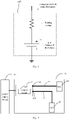
- As illustrated in
Fig. 1 , in the charging process, the voltage across both ends of the cell typically includes two parts. The first part is the true voltage of the cell, and the other part is a floating voltage caused by internal resistance of the cell. The true voltage of the cell refers to a stable voltage between positive and negative electrodes of the cell. The internal resistance of the cell may include ohmic internal resistance (which is also called direct current resistance) and polarization resistance of the cell. The floating voltage caused by the internal resistance of the cell may also be referred to as a "virtual voltage" caused by the internal resistance of the cell. - In the constant current charging stage, as the charging current is great, the floating voltage of the cell is also great. When the voltage across both ends of the cell reaches the rated voltage of the cell, the true voltage of the cell does not reach the rated voltage actually. In the constant voltage charging stage, the charging current is gradually reduced, and the floating voltage caused by the internal resistance of the cell is also gradually reduced. When the charging current of the cell is reduced to the constant voltage charging cut-off current, the floating voltage caused by the internal resistance of the cell is reduced to a negligible degree, and the true voltage of the cell approximately reaches the rated voltage of the cell.
- However, in the foregoing conventional charging method, the charging time of the constant voltage charging stage of the cell is long, resulting in a slow charging speed of the cell.
- In order to increase the charging speed of the cell, the charging time of the constant current charging needs to be increased as much as possible. Experiments show that the cell will not be damaged as long as the true voltage of the cell is not overvoltage in the charging process. Therefore, in the present disclosure, the constant current charging cut-off voltage is not set to be the rated voltage of the cell, but is set to be greater than the rated voltage of the cell, and the value of the constant current charging cut-off voltage may enable the true voltage of the cell not to be overvoltage in the constant current charging process, so that the constant current charging time may be prolonged as much as possible. A determination method of the constant current charging cut-off voltage will be described in detail below with specific embodiments, and will not described in detail here.
- In the constant current charging stage, the charging current of the cell is usually great. In order to avoid overheating of the whole machine, a power supply device (such as an adapter) may be adopted to perform direct charging on the cell. The direct charging means directly charging the cell through an external power supply device without passing through a charging management circuit. That is to say, in the direct charging process, an input current of the external power supply device may be directly applied to both ends of the cell, and the input current provided by the power supply device is not required to be converted by the charging management circuit, so that energy loss and heat generation caused by the conversion process are avoided.
- However, when the power supply device performs the direct charging on the cell, if power consumption of a load of a terminal where the cell is located is high, much energy is drawn from the charging current of the cell to supply power to the load, which results in a very small current entering the cell.
- As mentioned above, in the present disclosure, the constant current charging cut-off voltage is set to be greater than the rated voltage of the cell. If the power consumption of the load of the terminal is high, the current entering the cell is reduced, and thus the floating voltage of the cell is reduced, and most of the constant current charging cut-off voltage is applied to both ends of the cell. Consequently, the true voltage of the cell is overvoltage, and the cell is possibly damaged.
- In consideration of the above-mentioned problems that may exist in the direct charging scheme, in the constant current charging stage (or a part of the constant current charging stage) of the battery, the constant current charging is performed by using the charging management circuit in an embodiment of the present disclosure, so that the above-mentioned problems of the direct charging scheme can be avoided. With reference to
Fig. 2 , the embodiment of the present disclosure will be described in detail below by taking an example of charging the cell in the terminal. - As illustrated in
Fig. 2 , a terminal 20 may include acell 21 and acharging management circuit 22. Thecell 21 may include one cell or a plurality of cells connected in series. - The
charging management circuit 22 may be, for example, a charging management integrated circuit (IC), or referred to as a charging IC for short. Thecharging management circuit 22 may also be referred to as a charger in some cases. The chargingcontrol circuit 22 receives an input current provided by an externalpower supply device 30 in a wired or wireless manner, and perform constant voltage and/or constant current charging on thecell 21 according to the input current provided by thepower supply device 30. - The
charging management circuit 22 includes afirst output end 222, asecond output end 224, and acontrol circuit 226. - The
first output end 222 is configured to perform constant current charging on thecell 21. As illustrated inFig. 2 , a channel between thefirst output end 222 and thecell 21 is referred to as a chargingchannel 23. A charging current output from thefirst output end 222 flows into thecell 21 through the chargingchannel 23, so as to charge thecell 21. - The
second output end 224 is configured to supply power to aload 24 in the constant current charging process of thecell 21. Theload 24 may refer to a device in the terminal 20 that requires power, such as a processor, a sensor, etc. within the terminal. As illustrated inFig. 2 , a channel between thesecond output end 224 and theload 24 is referred to as a power supply channel, and thesecond output end 224 supplies power to theload 24 through thepower supply channel 25. - The
control circuit 226 is configured to stop the constant current charging when the voltage across both ends of thecell 21 reaches the constant current charging cut-off voltage of the constant current charging. - The constant current charging cut-off voltage is greater than the rated voltage of the
cell 21, and the configuration of the constant current charging cut-off voltage enables the true voltage of thecell 21 to be not overvoltage in the constant current charging process. - There may be various determination methods for determining the value of the constant current charging cut-off voltage, which is not limited in embodiments of the present disclosure. As an example, the constant current charging cut-off voltage may be determined empirically or experimentally. For example, in general, the constant current charging cut-off voltage Vthr may be set to any voltage satisfying the following relationship: 0<Vthr-Ve<0.2V, wherein Ve represents the rated voltage of the
cell 21. - As another example, the floating voltage of the
cell 21 at various temperatures and charging currents may be experimentally measured in advance. For example, assuming that the rated voltage of thecell 21 is Ve, and the floating voltage of thecell 21 at a certain temperature and a certain charging current is experimentally measured as Vf, the constant current charging cut-off voltage Vthr of thecell 21 at the temperature and the charging current may be set to any voltage satisfying the following condition: Ve<Vthr≦Ve+Vf, wherein Ve represents the rated voltage of thecell 21. - Further, in some embodiments, the constant current charging cut-off voltage may be configured such that when the voltage across both ends of the
cell 21 is charged to the constant current charging cut-off voltage, the true voltage of the cell is equal to the rated voltage of the cell. - For example, assuming that the rated voltage of the
cell 21 is Ve, and the floating voltage of thecell 21 at a certain temperature and a certain charging current is experimentally measured as Vf, the constant current charging cut-off voltage Vthr of thecell 21 at the temperature and the charging current may be set to Ve+Vf. In this manner, when the voltage across both ends of thecell 21 reaches Vthr, the true voltage across both ends of thecell 21 is Ve, which indicates that thecell 21 is fully charged, and the constant voltage charging is not required, so that the charging speed of thecell 21 is increased to a greater extent. - Unlike the direct charging scheme, when the constant current charging is performed with the
charging management circuit 22, theload 24 of the terminal 20 does not take electricity from the current entering thecell 21, but takes electricity from the externalpower supply device 30 through thesecond output end 224 of thecharging management circuit 22. Therefore, as long as the input current provided by thepower supply device 30 is ensured to be sufficiently great (for example, greater than a sum of the current required for supplying power to theload 24 and the charging current of the battery), even if the power consumption of theload 24 is large, the charging current entering thecell 21 is not affected, thereby effectively avoiding a problem that thecell 21 is overcharged for the reason that the charging current entering thecell 21 is reduced due to an excessive power consumption of theload 24. - As mentioned above, the distribution of the floating voltage of the
cell 21 at various temperatures (e.g., the temperature of the cell) and charging currents may be measured in advance through experiments. And then, in the actual charging process, the constant current charging cut-off voltage may be determined according to the present temperature (such as the present temperature of the cell) and charging current by using above-mentioned prior information, so that the constant current charging cut-off voltage is greater than the rated voltage of the cell, and the true voltage of the cell is not overvoltage in the constant current charging process. - As a possible implementation, a mapping relationship (hereinafter, referred to as a first mapping relationship) among the temperature, the charging current of the cell and the floating voltage of the cell may be established according to experiments. The first mapping relationship may be, for example, a mapping relationship table. In the actual charging process, the
control circuit 226 may determine the floating voltage of thecell 21 in the constant current charging process according to the present temperature, the charging current corresponding to the constant current charging, and the first mapping relationship established in advance; and determine the constant current charging cut-off voltage according to the floating voltage of thecell 21 in the constant current charging process. - For example, assuming that it is measured in advance through experiment that the floating voltage of the
cell 21 is 0.5V when the temperature is 35°C and the charging current is 1A, then a mapping relationship among these three may be established. In the actual charging process, if the charging current of the constant current charging is 1A and the temperature of thecell 21 is 35°C, it is determined that the floating voltage of thecell 21 at this time is 0.5V by querying the mapping relationship established in advance. Assuming that the rated voltage of thecell 21 is 4.25V, the constant current charging cut-off voltage may be determined to be 4.75V - As another possible implementation, a mapping relationship (hereinafter, referred to as a second mapping relationship) among the temperature, the charging current of the cell, and the constant current charging cut-off voltage may also be established directly according to experiments. The second mapping relationship may be, for example, a mapping relationship table. In the actual charging process, the
control circuit 226 may directly determine the constant current charging cut-off voltage according to the present temperature, the charging current corresponding to the constant current charging, and the second mapping relationship established in advance. - For example, assume that it is measured in advance through experiment that the floating voltage of the
cell 21 is 0.5V when the temperature is 35°C and the charging current is 1A. Since the rated voltage of thecell 21 is 4.25V, the constant current charging cut-off voltage may be set to 4.75V. In the actual charging process, if the charging current of the constant current charging is 1A and the temperature of thecell 21 is 35°C, the constant current charging cut-off voltage is directly determined to be 4.75V by querying the mapping relationship established in advance. - Embodiments of the present disclosure also provide the terminal 20 illustrated in
Fig. 2 . The terminal may include, but is not limited to, a device configured to receive/transmit communication signals via wired connection (for example, public switched telephone network (PSTN), digital subscriber line (DSL), digital cable, direct cable connection and/or another data connection/network) and/or via a wireless interface (for example, cellular network, wireless local area network (WLAN), digital TV network such as digital video broadcasting handheld (DVB-H) network, satellite network, an amplitude modulation-frequency modulation (AM-FM) broadcasting transmitter, and/or a wireless interface of another communication terminal). The terminal configured to communicate via the wireless interface may be referred to as "wireless communication terminal", "wireless terminal" and/or "mobile terminal". Examples of the mobile terminal include, but are not limited to a satellite phone or a cell phone, a terminal combining a cell radio phone and a personal communication system (PCS) having capability of data process, fax, and data communication, a personal digital assistant (PDA) including a radio phone, a pager, an Internet/Intranet access, a web browser, a notepad & address book, a calendar and/or a global positioning system (GPS) receiver, and a common laptop and/or handheld receiver, or other electronic devices including a radio phone transceiver. - As illustrated in
Fig. 3 , the terminal 20 may also include afast charging channel 27. In contrast, the chargingchannel 23 between thefirst output end 222 of thecharging management circuit 22 and thecell 21 may be referred to as a normal charging channel. - The
fast charging channel 27 may perform the direct charging on thecell 21 with the input current supplied from the externalpower supply device 30. Thefast charging channel 27 may perform constant current charging on thecell 21 with a large current before the constant current charging is performed on thecell 21 with thenormal charging channel 23. - Therefore, in the embodiment of the present disclosure, the constant current charging stage is divided into two different stages, namely, a stage of performing the constant current charging by using the fast charging channel 27 (hereinafter, referred to as a first constant current charging stage), and a stage of performing the constant current charging by using the normal charging channel 23 (hereinafter, referred to as a second constant current charging stage). In the first constant current charging stage, a relatively large charging current may be selected first, and direct charging is performed on the
cell 21 through thefast charging channel 27, without using thecharging management circuit 22 to convert the input voltage and/or the input current provided by thepower supply device 30, so that the heat generated by the whole machine is small. Moreover, since the charging current on thefast charging channel 27 is large, even if the power consumption of the load of the terminal 20 is large, the proportion of the current drawn by the load from the charging current may be small. Therefore, the possibility of overvoltage of thecell 21 is relatively small. - After the first constant current charging stage is completed, the second constant current charging stage may be entered. A small charging current (e.g., 1A or less than 1A) is selected to perform the constant current charging on the
cell 21 with thenormal charging channel 23. At this time, since the load directly takes electricity from thepower supply device 30, the charging current into thecell 21 is not reduced, and the problem of overvoltage does not occur, as long as it is ensured that the input current provided by thepower supply device 30 is sufficiently large. To sum up, the embodiment of the present disclosure may effectively prevent the cell from being overvoltage on the premise of improving the charging speed. - Device embodiments of the present disclosure are described in detail above in combination with
Figs. 1 to 3 , and method embodiments of the present disclosure will be described in detail below in combination withFig. 4 . It is to be understood that the description of the method embodiments corresponds to the description of the device embodiments, and therefore, for parts not described in detail, reference can be made to the foregoing device embodiments. -
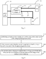
Fig. 4 is a schematic flow chart of a charging method according to an embodiment of the present disclosure. The method ofFig. 4 may include blocks S42 to S46. These blocks may be performed by thecharging management circuit 22 as described above. - At block S42, constant current charging is performed on a cell by using a first output end of the charging management circuit.
- At block S44, in the constant current charging process, power is supplied to a load by using a second output end of the charging management circuit.
- At block S46, the constant current charging is stopped when a voltage across both ends of the cell reaches a constant current charging cut-off voltage of the constant current charging, wherein the constant current charging cut-off voltage is greater than the rated voltage of the cell, and is configured such that the true voltage of the cell is not overvoltage in the constant current charging.
- Alternatively, the constant current charging cut-off voltage is determined based on a floating voltage of the cell in the constant current charging process.
- Alternatively, the method in
Fig. 4 further includes: determining the floating voltage of the cell in the constant current charging process according to a present temperature, a charging current corresponding to the constant current charging and a first mapping relationship established in advance, the first mapping relationship being a mapping relationship among the temperature, the charging current of the cell and the floating voltage of the cell; and determining the constant current charging cut-off voltage according to the floating voltage of the cell in the constant current charging process. - Alternatively, the method in
Fig. 4 further includes: determining the constant current charging cut-off voltage according to the present temperature, the charging current corresponding to the constant current charging and a second mapping relationship established in advance, the second mapping relationship being a mapping relationship among the temperature, the charging current of the cell and the constant current charging cut-off voltage. - Alternatively, the constant current charging cut-off voltage is configured such that when the voltage across both ends of the cell is charged to the constant current charging cut-off voltage, the true voltage of the cell is equal to the rated voltage of the cell.
- Alternatively, a charging channel between the first output end of the charging management circuit and the cell is the normal charging channel. The method in
Fig. 4 further includes: performing the constant current charging on the cell via a fast charging channel before performing the constant current charging on the cell via the normal charging channel, the fast charging channel being able to perform direct charging on the cell by using the input current provided by the power supply device, and the charging current of the constant current charging on the fast charging channel being greater than the charging current of the constant current charging on the normal charging channel. - In above embodiments, it is possible to implement the embodiments fully or partially by software, hardware, firmware or any other combination. When implemented by software, it is possible to implement the embodiments fully or partially in a form of computer program products. The computer program product includes one or more computer instructions. When the computer program instructions are loaded and executed by the computer, procedures or functions according to embodiments of the present disclosure are fully or partially generated. The computer may be a general-purpose computer, a special-purpose computer, a computer network, or any other programmable device. The computer instructions may be stored in a computer readable storage medium, or may be transmitted from one computer readable storage medium to another computer readable storage medium. For example, the computer instructions may be transmitted from one website, computer, server or data center to another website, computer, server or data center in a wired manner (for example, via coaxial cables, fiber optics, or DSL (digital subscriber line)) or in a wireless manner (for example, via infrared, WiFi or microwave). The computer readable storage medium may be any available medium that are accessible by the computer, or a data storage device such as a server or a data center integrated with one or more available medium. The available medium may be magnetic medium (for example, floppy disk, hard disk and tape), optical medium (for example, DVD (digital video disc)), or semiconductor medium (for example, SSD (solid state disk)).
- Those skilled in the art could be aware that, exemplary units and algorithm steps described in combination with embodiments disclosed herein may be implemented by electronic hardware, or by a combination of computer software and electronic hardware. Whether these functions are executed by hardware or software is dependent on particular use and design constraints of the technical solutions. Professionals may adopt different methods for different particular uses to implement described functions, which should not be regarded as going beyond the scope of the present disclosure.
- In several embodiments provided by the present disclosure, it should be understood that, the disclosed system, device and method may be implemented in other ways. For example, the device embodiments described above are merely illustrative. For example, the units are merely divided according to logic functions, and can be divided in other ways in actual implementation. For example, a plurality of units or components may be combined or may be integrated into another system, or some features may be ignored or not executed. In addition, the mutual coupling or direct coupling or communication connection illustrated or discussed may be via some interfaces, or direct coupling or communication connection of devices or units may be in an electrical, mechanical, or other form.
- The units described as separate parts may or may not be physically separated. Parts displayed as units may or may not be physical units, i.e., the parts may be located in one place, or may be distributed on a plurality of network units. Some or all of the units can be selected according to actual needs to achieve purposes of solutions of the embodiments.
- Moreover, respective functional units in respective embodiments of the present disclosure may be integrated in one processing unit, or the respective units may be separate physical existence, or two or more units may be integrated in one unit.
- Above description is merely specific implementation of the present disclosure. However, the protection scope of the present disclosure is not limited to this. Any change or substitute that is conceivable by those skilled in the art should be in the protection scope of the present disclosure. Thus, the protection scope of the present disclosure should be defined as the protection scope of claims.
Claims (13)
- A charging management circuit (22) for a terminal (20), said charging management circuit (22) configured to receive an input current from an external power supply device (30), said charging management circuit (22) comprising:a first output end (222), configured to perform constant current charging on a cell (21) of the terminal (20) through a charging channel (23) between the first output end (222) and the cell (21);a second output end (224), configured to supply power to a load (24) of the terminal during the constant current charging through a power supply channel (25) between the second output end (224) and the load (24) such that the load (24) of the terminal does not take electricity from the current entering the cell (21) but takes electricity from the external power supply device (30) through the second output end (224) of the charging management circuit (22); anda control circuit (226), configured to stop the constant current charging when a voltage across both ends of the cell (21) reaches a constant current charging cut-off voltage of the constant current charging, wherein the constant current charging cut-off voltage is greater than a rated voltage of the cell, and is configured such that a true voltage of the cell is not overvoltage in the constant current charging, wherein the voltage across both ends of the cell (21) includes the true voltage of the cell (21) and a floating voltage, wherein the true voltage of the cell (21) is the stable voltage between positive and negative electrodes of the cell (21) and the floating voltage is caused by internal resistance of the cell (21).
- The charging management circuit (22) according to claim 1, wherein the constant current charging cut-off voltage is determined based on the floating voltage of the cell (21) in the constant current charging.
- The charging management circuit (22) according to claim 1 or 2, wherein the control circuit (226) is further configured to:determine the floating voltage of the cell (21) in the constant current charging according to a present temperature, a charging current corresponding to the constant current charging and a first mapping relationship established in advance, the first mapping relationship being a mapping relationship among the temperature, the charging current of the cell (21) and the floating voltage of the cell (21); anddetermine the constant current charging cut-off voltage according to the floating voltage of the cell (21) in the constant current charging.
- The charging management circuit (22) according to claim 1 or 2, wherein the control circuit (226) is further configured to:
determine the constant current charging cut-off voltage according to a present temperature, the charging current corresponding to the constant current charging and a second mapping relationship established in advance, the second mapping relationship being a mapping relationship among the temperature, the charging current of the cell (21) and the constant current charging cut-off voltage. - The charging management circuit (22) according to any one of claims 1 to 4, wherein the constant current charging cut-off voltage is configured such that when the voltage across both ends of the cell (21) is charged to the constant current charging cut-off voltage, the true voltage of the cell (21) is equal to the rated voltage of the cell (21).
- A terminal (20), comprising:a cell (21);a load (24); andthe charging management circuit (22) according to any one of claims 1 to 5.
- The terminal (20) according to claim 6, wherein a charging channel (23) between a first output end (222) of the charging management circuit (22) and the cell (21) is a normal charging channel, and
the terminal (20) further comprises:
a fast charging channel (27), being capable of performing direct charging on the cell (21) by using an input current provided by the power supply device (30), and is configured to perform constant current charging on the cell (21) before performing the constant current charging on the cell (21) via the normal charging channel (23), wherein a charging current of the constant current charging on the fast charging channel (27) is greater than a charging current of the constant current charging on the normal charging channel (23). - A charging method, comprising:performing constant current charging on a cell (21) of a terminal (20) by using a first output end (22) of a charging management circuit (22) through a charging channel (23) between the first output end (222) and the cell (21), wherein said charging management circuit (22) is configured to receive an input current from an external power supply device (30);supplying power to a load (24) of the terminal (20) by using a second output end (224) of the charging management circuit (22) in the constant current charging through a power supply channel (25) between the second output end (224) and the load (24) such that the load (24) of the terminal does not take electricity from the current entering the cell (21) but takes electricity from the external power supply device (30) through the second output end (224) of the charging management circuit (22); andstopping the constant current charging when a voltage across both ends of the cell (21) reaches a constant current charging cut-off voltage of the constant current charging, wherein the constant current charging cut-off voltage is greater than a rated voltage of the cell (21), and is configured such that a true voltage of the cell (21) is not overvoltage in the constant current charging, wherein the voltage across both ends of the cell (21) includes the true voltage of the cell (21) and a floating voltage, wherein the true voltage of the cell (21) is the stable voltage between positive and negative electrodes of the cell (21) and the floating voltage is caused by internal resistance of the cell (21).
- The charging method according to claim 8, wherein the constant current charging cut-off voltage is determined based on the floating voltage of the cell (21) in the constant current charging.
- The charging method according to claim 8 or 9, further comprising:determining the floating voltage of the cell (21) in the constant current charging according to a present temperature, a charging current corresponding to the constant current charging and a first mapping relationship established in advance, the first mapping relationship being a mapping relationship among the temperature, the charging current of the cell and the floating voltage of the cell (21); anddetermining the constant current charging cut-off voltage according to the floating voltage of the cell (21) in the constant current charging.
- The charging method according to claim 8 or 9, further comprising:
determining the constant current charging cut-off voltage according to a present temperature, the charging current corresponding to the constant current charging and a second mapping relationship established in advance, the second mapping relationship being a mapping relationship among the temperature, the charging current of the cell (21) and the constant current charging cut-off voltage. - The charging method according to any one of claims 8 to 11, wherein the constant current charging cut-off voltage is configured such that when the voltage across both ends of the cell is charged to the constant current charging cut-off voltage, the true voltage of the cell is equal to the rated voltage of the cell.
- The charging method according to any one of claims 8 to 12, wherein a charging channel between the first output end of the charging management circuit and the cell is a normal charging channel, and
the method further comprises:
performing the constant current charging on the cell via a fast charging channel before performing the constant current charging on the cell via the normal charging channel, the fast charging channel being able to perform direct charging on the cell by using an input current provided by the power supply device, and a charging current of the constant current charging on the fast charging channel being greater than a charging current of the constant current charging on the normal charging channel.
Applications Claiming Priority (1)
| Application Number | Priority Date | Filing Date | Title |
|---|---|---|---|
| PCT/CN2018/105178 WO2020051790A1 (en) | 2018-09-12 | 2018-09-12 | Charging management circuit, terminal and charging method |
Publications (3)
| Publication Number | Publication Date |
|---|---|
| EP3672016A1 EP3672016A1 (en) | 2020-06-24 |
| EP3672016A4 EP3672016A4 (en) | 2020-10-28 |
| EP3672016B1 true EP3672016B1 (en) | 2022-12-28 |
Family
ID=68248716
Family Applications (1)
| Application Number | Title | Priority Date | Filing Date |
|---|---|---|---|
| EP18932974.1A Active EP3672016B1 (en) | 2018-09-12 | 2018-09-12 | Charging management circuit, terminal and charging method |
Country Status (4)
| Country | Link |
|---|---|
| US (1) | US11381102B2 (en) |
| EP (1) | EP3672016B1 (en) |
| CN (1) | CN110383618A (en) |
| WO (1) | WO2020051790A1 (en) |
Families Citing this family (7)
| Publication number | Priority date | Publication date | Assignee | Title |
|---|---|---|---|---|
| RU2730547C1 (en) * | 2018-05-31 | 2020-08-24 | Гуандун Оппо Мобайл Телекоммьюникейшнс Корп., Лтд. | Charging method and charging device |
| WO2021077271A1 (en) * | 2019-10-21 | 2021-04-29 | 宁德新能源科技有限公司 | Charging method, electronic device, and storage medium |
| CN111082487B (en) * | 2019-12-25 | 2024-02-02 | Oppo广东移动通信有限公司 | Charging control method and device, electronic equipment |
| CN111525651B (en) * | 2020-05-27 | 2025-03-21 | 广东小天才科技有限公司 | A charging method, a charging chip and a terminal device |
| CN114156957B (en) | 2020-09-07 | 2025-03-25 | 北京小米移动软件有限公司 | Battery charging method, device and storage medium |
| CN114006429B (en) * | 2021-10-25 | 2024-11-05 | 北京小米移动软件有限公司 | Charging method, device, terminal equipment and computer readable storage medium |
| CN114944392A (en) * | 2022-03-25 | 2022-08-26 | 中国科学院微电子研究所 | Semiconductor device and manufacturing method thereof |
Citations (3)
| Publication number | Priority date | Publication date | Assignee | Title |
|---|---|---|---|---|
| US20130147277A1 (en) * | 2011-12-08 | 2013-06-13 | O2Micro Inc. | Power management system |
| CN107612075A (en) * | 2017-09-27 | 2018-01-19 | 宁德时代新能源科技股份有限公司 | Battery charging method, device, equipment and storage medium |
| EP3285357A1 (en) * | 2016-02-05 | 2018-02-21 | Guangdong Oppo Mobile Telecommunications Corp., Ltd. | Charging system, charging method, and power adapter for terminal |
Family Cites Families (21)
| Publication number | Priority date | Publication date | Assignee | Title |
|---|---|---|---|---|
| DE69942848D1 (en) * | 1998-06-09 | 2010-11-25 | Makita Corp | battery charger |
| CN1983676A (en) * | 2006-01-27 | 2007-06-20 | 松下电器产业株式会社 | Lithium ion secondary battery and charge system therefor |
| CN100392943C (en) * | 2006-04-11 | 2008-06-04 | 广州市番禺丰江电池制造有限公司 | Quick charge method and device |
| CN1949620A (en) | 2006-11-03 | 2007-04-18 | 中国科学院电工研究所 | Power managing system with multi-charging modes |
| CN101636872A (en) * | 2007-03-07 | 2010-01-27 | 松下电器产业株式会社 | Quick charging method of lithium based secondary battery and electronic apparatus employing it |
| JP4805223B2 (en) * | 2007-07-27 | 2011-11-02 | レノボ・シンガポール・プライベート・リミテッド | Charging system and charging method |
| FR2945684B1 (en) * | 2009-05-14 | 2011-06-17 | Commissariat Energie Atomique | CONVERTER CIRCUIT AND ELECTRONIC SYSTEM COMPRISING SUCH A CIRCUIT |
| US8754614B2 (en) * | 2009-07-17 | 2014-06-17 | Tesla Motors, Inc. | Fast charging of battery using adjustable voltage control |
| CN101640296B (en) | 2009-08-28 | 2011-09-28 | 广州丰江电池新技术股份有限公司 | Quick charging method for improving storage battery specific capacity |
| US9077198B2 (en) * | 2011-12-30 | 2015-07-07 | Thomas Szepesi | Battery charging method and circuit |
| US9337683B2 (en) * | 2012-12-20 | 2016-05-10 | Powergenix Systems, Inc. | Controlling battery states of charge in systems having separate power sources |
| CN103107378B (en) * | 2013-02-05 | 2016-08-17 | 广东欧珀移动通信有限公司 | The method for charging batteries of a kind of mobile terminal and device mobile terminal |
| CN103138022A (en) | 2013-03-07 | 2013-06-05 | 清华大学 | Battery pack charging method |
| KR102502450B1 (en) * | 2015-11-02 | 2023-02-22 | 삼성전자주식회사 | Method and apparatus of charging battery |
| CN105262173A (en) | 2015-11-03 | 2016-01-20 | 福建奥通迈胜电力科技有限公司 | Wireless charger suitable for fault indicator |
| JP2017147787A (en) * | 2016-02-15 | 2017-08-24 | 株式会社東芝 | Multi-output dc-dc converter |
| CN105939040A (en) * | 2016-06-20 | 2016-09-14 | 深圳天珑无线科技有限公司 | Battery charging circuit, battery charging method and electronic equipment |
| KR102508958B1 (en) * | 2016-10-06 | 2023-03-13 | 삼성전자주식회사 | Electronic device for performing charging and method for controlling thereof |
| US20190229548A1 (en) | 2016-12-12 | 2019-07-25 | Shenzhen Royole Technologies Co. Ltd. | Electronic device and charging control method thereof |
| CN106887884A (en) | 2016-12-28 | 2017-06-23 | 深圳天珑无线科技有限公司 | The charging method and battery charging equipment of battery |
| CN107768757B (en) * | 2017-10-20 | 2019-06-04 | 西北工业大学 | A fast charging method for internal resistance compensation of single-cell lithium battery |
-
2018
- 2018-09-12 EP EP18932974.1A patent/EP3672016B1/en active Active
- 2018-09-12 WO PCT/CN2018/105178 patent/WO2020051790A1/en not_active Ceased
- 2018-09-12 US US16/620,858 patent/US11381102B2/en active Active
- 2018-09-12 CN CN201880015957.XA patent/CN110383618A/en active Pending
Patent Citations (4)
| Publication number | Priority date | Publication date | Assignee | Title |
|---|---|---|---|---|
| US20130147277A1 (en) * | 2011-12-08 | 2013-06-13 | O2Micro Inc. | Power management system |
| EP3285357A1 (en) * | 2016-02-05 | 2018-02-21 | Guangdong Oppo Mobile Telecommunications Corp., Ltd. | Charging system, charging method, and power adapter for terminal |
| CN107612075A (en) * | 2017-09-27 | 2018-01-19 | 宁德时代新能源科技股份有限公司 | Battery charging method, device, equipment and storage medium |
| EP3462566A1 (en) * | 2017-09-27 | 2019-04-03 | Contemporary Amperex Technology Co., Limited | Method, apparatus, and device for charging a battery and storage medium |
Also Published As
| Publication number | Publication date |
|---|---|
| US20210336465A1 (en) | 2021-10-28 |
| US11381102B2 (en) | 2022-07-05 |
| EP3672016A4 (en) | 2020-10-28 |
| EP3672016A1 (en) | 2020-06-24 |
| CN110383618A (en) | 2019-10-25 |
| WO2020051790A1 (en) | 2020-03-19 |
Similar Documents
| Publication | Publication Date | Title |
|---|---|---|
| EP3672016B1 (en) | Charging management circuit, terminal and charging method | |
| US20220239116A1 (en) | Devices to be charged and charging control methods | |
| US10797502B2 (en) | Charging method and electronic devices | |
| US12249859B2 (en) | Adaptive power systems and techniques | |
| EP3678277B1 (en) | Quick charging method for battery, charging device, device to be charged and charging system | |
| US8854013B2 (en) | System for monitoring a battery charger | |
| WO2023216483A1 (en) | Energy storage system control method and apparatus, device, storage medium, and program product | |
| US20150145468A1 (en) | Device and chip for controlling charging, and user terminal | |
| US12556018B2 (en) | Charging management apparatus, charging management method, and electric vehicle | |
| EP3934053B1 (en) | Power supply device, electronic apparatus, and power supply method | |
| US20210313822A1 (en) | Wireless charging method and device to be charged | |
| CN111262296A (en) | Double-battery charging structure and mobile terminal | |
| CN111095720A (en) | Charging method and charging device | |
| CN110879361A (en) | A method, device and electronic device for estimating remaining power of a battery | |
| CN112290652A (en) | To-be-charged equipment, wireless charging method and system | |
| WO2022160182A1 (en) | Charging method and power conversion device | |
| CN110892575B (en) | Battery pack with coupling identification function | |
| US10903676B2 (en) | Semiconductor device | |
| CN112671052A (en) | Device to be charged and charging method | |
| CN113872303A (en) | Charging control method, device, electronic device and storage medium | |
| CN116667473B (en) | Control circuit, circuit control method and electronic equipment | |
| CN215733552U (en) | Charger, terminal and charging system | |
| CN110676898B (en) | Equipment to be charged | |
| WO2014190831A1 (en) | Battery control method and device, terminal and computer storage medium | |
| CN223273883U (en) | Power supply control circuit and charger |
Legal Events
| Date | Code | Title | Description |
|---|---|---|---|
| STAA | Information on the status of an ep patent application or granted ep patent |
Free format text: STATUS: UNKNOWN |
|
| STAA | Information on the status of an ep patent application or granted ep patent |
Free format text: STATUS: THE INTERNATIONAL PUBLICATION HAS BEEN MADE |
|
| PUAI | Public reference made under article 153(3) epc to a published international application that has entered the european phase |
Free format text: ORIGINAL CODE: 0009012 |
|
| STAA | Information on the status of an ep patent application or granted ep patent |
Free format text: STATUS: REQUEST FOR EXAMINATION WAS MADE |
|
| 17P | Request for examination filed |
Effective date: 20200319 |
|
| AK | Designated contracting states |
Kind code of ref document: A1 Designated state(s): AL AT BE BG CH CY CZ DE DK EE ES FI FR GB GR HR HU IE IS IT LI LT LU LV MC MK MT NL NO PL PT RO RS SE SI SK SM TR |
|
| AX | Request for extension of the european patent |
Extension state: BA ME |
|
| A4 | Supplementary search report drawn up and despatched |
Effective date: 20200924 |
|
| RIC1 | Information provided on ipc code assigned before grant |
Ipc: H02J 7/00 20060101AFI20200918BHEP |
|
| STAA | Information on the status of an ep patent application or granted ep patent |
Free format text: STATUS: EXAMINATION IS IN PROGRESS |
|
| 17Q | First examination report despatched |
Effective date: 20210311 |
|
| DAV | Request for validation of the european patent (deleted) | ||
| DAX | Request for extension of the european patent (deleted) | ||
| GRAP | Despatch of communication of intention to grant a patent |
Free format text: ORIGINAL CODE: EPIDOSNIGR1 |
|
| STAA | Information on the status of an ep patent application or granted ep patent |
Free format text: STATUS: GRANT OF PATENT IS INTENDED |
|
| INTG | Intention to grant announced |
Effective date: 20220726 |
|
| GRAS | Grant fee paid |
Free format text: ORIGINAL CODE: EPIDOSNIGR3 |
|
| GRAA | (expected) grant |
Free format text: ORIGINAL CODE: 0009210 |
|
| STAA | Information on the status of an ep patent application or granted ep patent |
Free format text: STATUS: THE PATENT HAS BEEN GRANTED |
|
| AK | Designated contracting states |
Kind code of ref document: B1 Designated state(s): AL AT BE BG CH CY CZ DE DK EE ES FI FR GB GR HR HU IE IS IT LI LT LU LV MC MK MT NL NO PL PT RO RS SE SI SK SM TR |
|
| REG | Reference to a national code |
Ref country code: GB Ref legal event code: FG4D |
|
| REG | Reference to a national code |
Ref country code: CH Ref legal event code: EP |
|
| REG | Reference to a national code |
Ref country code: DE Ref legal event code: R096 Ref document number: 602018044911 Country of ref document: DE |
|
| REG | Reference to a national code |
Ref country code: AT Ref legal event code: REF Ref document number: 1541071 Country of ref document: AT Kind code of ref document: T Effective date: 20230115 |
|
| REG | Reference to a national code |
Ref country code: IE Ref legal event code: FG4D |
|
| REG | Reference to a national code |
Ref country code: LT Ref legal event code: MG9D |
|
| PG25 | Lapsed in a contracting state [announced via postgrant information from national office to epo] |
Ref country code: SE Free format text: LAPSE BECAUSE OF FAILURE TO SUBMIT A TRANSLATION OF THE DESCRIPTION OR TO PAY THE FEE WITHIN THE PRESCRIBED TIME-LIMIT Effective date: 20221228 Ref country code: NO Free format text: LAPSE BECAUSE OF FAILURE TO SUBMIT A TRANSLATION OF THE DESCRIPTION OR TO PAY THE FEE WITHIN THE PRESCRIBED TIME-LIMIT Effective date: 20230328 Ref country code: LT Free format text: LAPSE BECAUSE OF FAILURE TO SUBMIT A TRANSLATION OF THE DESCRIPTION OR TO PAY THE FEE WITHIN THE PRESCRIBED TIME-LIMIT Effective date: 20221228 Ref country code: FI Free format text: LAPSE BECAUSE OF FAILURE TO SUBMIT A TRANSLATION OF THE DESCRIPTION OR TO PAY THE FEE WITHIN THE PRESCRIBED TIME-LIMIT Effective date: 20221228 |
|
| REG | Reference to a national code |
Ref country code: NL Ref legal event code: MP Effective date: 20221228 |
|
| REG | Reference to a national code |
Ref country code: AT Ref legal event code: MK05 Ref document number: 1541071 Country of ref document: AT Kind code of ref document: T Effective date: 20221228 |
|
| PG25 | Lapsed in a contracting state [announced via postgrant information from national office to epo] |
Ref country code: RS Free format text: LAPSE BECAUSE OF FAILURE TO SUBMIT A TRANSLATION OF THE DESCRIPTION OR TO PAY THE FEE WITHIN THE PRESCRIBED TIME-LIMIT Effective date: 20221228 Ref country code: LV Free format text: LAPSE BECAUSE OF FAILURE TO SUBMIT A TRANSLATION OF THE DESCRIPTION OR TO PAY THE FEE WITHIN THE PRESCRIBED TIME-LIMIT Effective date: 20221228 Ref country code: HR Free format text: LAPSE BECAUSE OF FAILURE TO SUBMIT A TRANSLATION OF THE DESCRIPTION OR TO PAY THE FEE WITHIN THE PRESCRIBED TIME-LIMIT Effective date: 20221228 Ref country code: GR Free format text: LAPSE BECAUSE OF FAILURE TO SUBMIT A TRANSLATION OF THE DESCRIPTION OR TO PAY THE FEE WITHIN THE PRESCRIBED TIME-LIMIT Effective date: 20230329 |
|
| P01 | Opt-out of the competence of the unified patent court (upc) registered |
Effective date: 20230412 |
|
| PG25 | Lapsed in a contracting state [announced via postgrant information from national office to epo] |
Ref country code: NL Free format text: LAPSE BECAUSE OF FAILURE TO SUBMIT A TRANSLATION OF THE DESCRIPTION OR TO PAY THE FEE WITHIN THE PRESCRIBED TIME-LIMIT Effective date: 20221228 |
|
| PG25 | Lapsed in a contracting state [announced via postgrant information from national office to epo] |
Ref country code: SM Free format text: LAPSE BECAUSE OF FAILURE TO SUBMIT A TRANSLATION OF THE DESCRIPTION OR TO PAY THE FEE WITHIN THE PRESCRIBED TIME-LIMIT Effective date: 20221228 Ref country code: RO Free format text: LAPSE BECAUSE OF FAILURE TO SUBMIT A TRANSLATION OF THE DESCRIPTION OR TO PAY THE FEE WITHIN THE PRESCRIBED TIME-LIMIT Effective date: 20221228 Ref country code: PT Free format text: LAPSE BECAUSE OF FAILURE TO SUBMIT A TRANSLATION OF THE DESCRIPTION OR TO PAY THE FEE WITHIN THE PRESCRIBED TIME-LIMIT Effective date: 20230428 Ref country code: ES Free format text: LAPSE BECAUSE OF FAILURE TO SUBMIT A TRANSLATION OF THE DESCRIPTION OR TO PAY THE FEE WITHIN THE PRESCRIBED TIME-LIMIT Effective date: 20221228 Ref country code: EE Free format text: LAPSE BECAUSE OF FAILURE TO SUBMIT A TRANSLATION OF THE DESCRIPTION OR TO PAY THE FEE WITHIN THE PRESCRIBED TIME-LIMIT Effective date: 20221228 Ref country code: CZ Free format text: LAPSE BECAUSE OF FAILURE TO SUBMIT A TRANSLATION OF THE DESCRIPTION OR TO PAY THE FEE WITHIN THE PRESCRIBED TIME-LIMIT Effective date: 20221228 Ref country code: AT Free format text: LAPSE BECAUSE OF FAILURE TO SUBMIT A TRANSLATION OF THE DESCRIPTION OR TO PAY THE FEE WITHIN THE PRESCRIBED TIME-LIMIT Effective date: 20221228 |
|
| PG25 | Lapsed in a contracting state [announced via postgrant information from national office to epo] |
Ref country code: SK Free format text: LAPSE BECAUSE OF FAILURE TO SUBMIT A TRANSLATION OF THE DESCRIPTION OR TO PAY THE FEE WITHIN THE PRESCRIBED TIME-LIMIT Effective date: 20221228 Ref country code: PL Free format text: LAPSE BECAUSE OF FAILURE TO SUBMIT A TRANSLATION OF THE DESCRIPTION OR TO PAY THE FEE WITHIN THE PRESCRIBED TIME-LIMIT Effective date: 20221228 Ref country code: IS Free format text: LAPSE BECAUSE OF FAILURE TO SUBMIT A TRANSLATION OF THE DESCRIPTION OR TO PAY THE FEE WITHIN THE PRESCRIBED TIME-LIMIT Effective date: 20230428 Ref country code: AL Free format text: LAPSE BECAUSE OF FAILURE TO SUBMIT A TRANSLATION OF THE DESCRIPTION OR TO PAY THE FEE WITHIN THE PRESCRIBED TIME-LIMIT Effective date: 20221228 |
|
| REG | Reference to a national code |
Ref country code: DE Ref legal event code: R097 Ref document number: 602018044911 Country of ref document: DE |
|
| PG25 | Lapsed in a contracting state [announced via postgrant information from national office to epo] |
Ref country code: DK Free format text: LAPSE BECAUSE OF FAILURE TO SUBMIT A TRANSLATION OF THE DESCRIPTION OR TO PAY THE FEE WITHIN THE PRESCRIBED TIME-LIMIT Effective date: 20221228 |
|
| PLBE | No opposition filed within time limit |
Free format text: ORIGINAL CODE: 0009261 |
|
| STAA | Information on the status of an ep patent application or granted ep patent |
Free format text: STATUS: NO OPPOSITION FILED WITHIN TIME LIMIT |
|
| 26N | No opposition filed |
Effective date: 20230929 |
|
| PG25 | Lapsed in a contracting state [announced via postgrant information from national office to epo] |
Ref country code: SI Free format text: LAPSE BECAUSE OF FAILURE TO SUBMIT A TRANSLATION OF THE DESCRIPTION OR TO PAY THE FEE WITHIN THE PRESCRIBED TIME-LIMIT Effective date: 20221228 |
|
| REG | Reference to a national code |
Ref country code: CH Ref legal event code: PL |
|
| PG25 | Lapsed in a contracting state [announced via postgrant information from national office to epo] |
Ref country code: LU Free format text: LAPSE BECAUSE OF NON-PAYMENT OF DUE FEES Effective date: 20230912 |
|
| REG | Reference to a national code |
Ref country code: BE Ref legal event code: MM Effective date: 20230930 |
|
| PG25 | Lapsed in a contracting state [announced via postgrant information from national office to epo] |
Ref country code: LU Free format text: LAPSE BECAUSE OF NON-PAYMENT OF DUE FEES Effective date: 20230912 Ref country code: IT Free format text: LAPSE BECAUSE OF FAILURE TO SUBMIT A TRANSLATION OF THE DESCRIPTION OR TO PAY THE FEE WITHIN THE PRESCRIBED TIME-LIMIT Effective date: 20221228 Ref country code: MC Free format text: LAPSE BECAUSE OF FAILURE TO SUBMIT A TRANSLATION OF THE DESCRIPTION OR TO PAY THE FEE WITHIN THE PRESCRIBED TIME-LIMIT Effective date: 20221228 |
|
| REG | Reference to a national code |
Ref country code: IE Ref legal event code: MM4A |
|
| PG25 | Lapsed in a contracting state [announced via postgrant information from national office to epo] |
Ref country code: IE Free format text: LAPSE BECAUSE OF NON-PAYMENT OF DUE FEES Effective date: 20230912 |
|
| PG25 | Lapsed in a contracting state [announced via postgrant information from national office to epo] |
Ref country code: CH Free format text: LAPSE BECAUSE OF NON-PAYMENT OF DUE FEES Effective date: 20230930 |
|
| PG25 | Lapsed in a contracting state [announced via postgrant information from national office to epo] |
Ref country code: IE Free format text: LAPSE BECAUSE OF NON-PAYMENT OF DUE FEES Effective date: 20230912 Ref country code: CH Free format text: LAPSE BECAUSE OF NON-PAYMENT OF DUE FEES Effective date: 20230930 |
|
| PG25 | Lapsed in a contracting state [announced via postgrant information from national office to epo] |
Ref country code: BE Free format text: LAPSE BECAUSE OF NON-PAYMENT OF DUE FEES Effective date: 20230930 |
|
| PG25 | Lapsed in a contracting state [announced via postgrant information from national office to epo] |
Ref country code: BG Free format text: LAPSE BECAUSE OF FAILURE TO SUBMIT A TRANSLATION OF THE DESCRIPTION OR TO PAY THE FEE WITHIN THE PRESCRIBED TIME-LIMIT Effective date: 20221228 |
|
| PG25 | Lapsed in a contracting state [announced via postgrant information from national office to epo] |
Ref country code: BG Free format text: LAPSE BECAUSE OF FAILURE TO SUBMIT A TRANSLATION OF THE DESCRIPTION OR TO PAY THE FEE WITHIN THE PRESCRIBED TIME-LIMIT Effective date: 20221228 |
|
| PG25 | Lapsed in a contracting state [announced via postgrant information from national office to epo] |
Ref country code: CY Free format text: LAPSE BECAUSE OF FAILURE TO SUBMIT A TRANSLATION OF THE DESCRIPTION OR TO PAY THE FEE WITHIN THE PRESCRIBED TIME-LIMIT; INVALID AB INITIO Effective date: 20180912 |
|
| PG25 | Lapsed in a contracting state [announced via postgrant information from national office to epo] |
Ref country code: HU Free format text: LAPSE BECAUSE OF FAILURE TO SUBMIT A TRANSLATION OF THE DESCRIPTION OR TO PAY THE FEE WITHIN THE PRESCRIBED TIME-LIMIT; INVALID AB INITIO Effective date: 20180912 |
|
| PGFP | Annual fee paid to national office [announced via postgrant information from national office to epo] |
Ref country code: DE Payment date: 20250923 Year of fee payment: 8 |
|
| PGFP | Annual fee paid to national office [announced via postgrant information from national office to epo] |
Ref country code: GB Payment date: 20250915 Year of fee payment: 8 |
|
| PGFP | Annual fee paid to national office [announced via postgrant information from national office to epo] |
Ref country code: FR Payment date: 20250915 Year of fee payment: 8 |
|
| PG25 | Lapsed in a contracting state [announced via postgrant information from national office to epo] |
Ref country code: TR Free format text: LAPSE BECAUSE OF FAILURE TO SUBMIT A TRANSLATION OF THE DESCRIPTION OR TO PAY THE FEE WITHIN THE PRESCRIBED TIME-LIMIT Effective date: 20221228 |