EP3672012A1 - Verfahren zur optimierung der energieversorgung aus einer elektrischen energiequelle in einer elektrischen anlage und vorrichtung zur durchführung eines solchen verfahrens - Google Patents
Verfahren zur optimierung der energieversorgung aus einer elektrischen energiequelle in einer elektrischen anlage und vorrichtung zur durchführung eines solchen verfahrens Download PDFInfo
- Publication number
- EP3672012A1 EP3672012A1 EP19211986.5A EP19211986A EP3672012A1 EP 3672012 A1 EP3672012 A1 EP 3672012A1 EP 19211986 A EP19211986 A EP 19211986A EP 3672012 A1 EP3672012 A1 EP 3672012A1
- Authority
- EP
- European Patent Office
- Prior art keywords
- power
- converter
- active
- electrical
- active power
- Prior art date
- Legal status (The legal status is an assumption and is not a legal conclusion. Google has not performed a legal analysis and makes no representation as to the accuracy of the status listed.)
- Granted
Links
Images


Classifications
-
- H—ELECTRICITY
- H02—GENERATION; CONVERSION OR DISTRIBUTION OF ELECTRIC POWER
- H02J—ELECTRIC POWER NETWORKS; CIRCUIT ARRANGEMENTS OR SYSTEMS FOR SUPPLYING OR DISTRIBUTING ELECTRIC POWER; SYSTEMS FOR STORING ELECTRIC ENERGY
- H02J3/00—Circuit arrangements for AC mains or AC distribution networks
- H02J3/38—Arrangements for feeding a single network from two or more generators or sources in parallel; Arrangements for feeding already energised networks from additional generators or sources in parallel
- H02J3/381—Dispersed generators
-
- H—ELECTRICITY
- H02—GENERATION; CONVERSION OR DISTRIBUTION OF ELECTRIC POWER
- H02J—ELECTRIC POWER NETWORKS; CIRCUIT ARRANGEMENTS OR SYSTEMS FOR SUPPLYING OR DISTRIBUTING ELECTRIC POWER; SYSTEMS FOR STORING ELECTRIC ENERGY
- H02J3/00—Circuit arrangements for AC mains or AC distribution networks
- H02J3/12—Arrangements for adjusting voltage in AC networks by changing a characteristic of the network load
- H02J3/16—Arrangements for adjusting voltage in AC networks by changing a characteristic of the network load by adjustment of reactive power
-
- H—ELECTRICITY
- H02—GENERATION; CONVERSION OR DISTRIBUTION OF ELECTRIC POWER
- H02J—ELECTRIC POWER NETWORKS; CIRCUIT ARRANGEMENTS OR SYSTEMS FOR SUPPLYING OR DISTRIBUTING ELECTRIC POWER; SYSTEMS FOR STORING ELECTRIC ENERGY
- H02J3/00—Circuit arrangements for AC mains or AC distribution networks
- H02J3/38—Arrangements for feeding a single network from two or more generators or sources in parallel; Arrangements for feeding already energised networks from additional generators or sources in parallel
- H02J3/46—Controlling the sharing of generated power between the generators, sources or networks
-
- H—ELECTRICITY
- H02—GENERATION; CONVERSION OR DISTRIBUTION OF ELECTRIC POWER
- H02J—ELECTRIC POWER NETWORKS; CIRCUIT ARRANGEMENTS OR SYSTEMS FOR SUPPLYING OR DISTRIBUTING ELECTRIC POWER; SYSTEMS FOR STORING ELECTRIC ENERGY
- H02J3/00—Circuit arrangements for AC mains or AC distribution networks
-
- H—ELECTRICITY
- H02—GENERATION; CONVERSION OR DISTRIBUTION OF ELECTRIC POWER
- H02J—ELECTRIC POWER NETWORKS; CIRCUIT ARRANGEMENTS OR SYSTEMS FOR SUPPLYING OR DISTRIBUTING ELECTRIC POWER; SYSTEMS FOR STORING ELECTRIC ENERGY
- H02J3/00—Circuit arrangements for AC mains or AC distribution networks
- H02J3/18—Arrangements for adjusting, eliminating or compensating reactive power in networks
-
- H—ELECTRICITY
- H02—GENERATION; CONVERSION OR DISTRIBUTION OF ELECTRIC POWER
- H02J—ELECTRIC POWER NETWORKS; CIRCUIT ARRANGEMENTS OR SYSTEMS FOR SUPPLYING OR DISTRIBUTING ELECTRIC POWER; SYSTEMS FOR STORING ELECTRIC ENERGY
- H02J3/00—Circuit arrangements for AC mains or AC distribution networks
- H02J3/38—Arrangements for feeding a single network from two or more generators or sources in parallel; Arrangements for feeding already energised networks from additional generators or sources in parallel
- H02J3/46—Controlling the sharing of generated power between the generators, sources or networks
- H02J3/48—Controlling the sharing of active power
-
- H—ELECTRICITY
- H02—GENERATION; CONVERSION OR DISTRIBUTION OF ELECTRIC POWER
- H02J—ELECTRIC POWER NETWORKS; CIRCUIT ARRANGEMENTS OR SYSTEMS FOR SUPPLYING OR DISTRIBUTING ELECTRIC POWER; SYSTEMS FOR STORING ELECTRIC ENERGY
- H02J3/00—Circuit arrangements for AC mains or AC distribution networks
- H02J3/38—Arrangements for feeding a single network from two or more generators or sources in parallel; Arrangements for feeding already energised networks from additional generators or sources in parallel
- H02J3/46—Controlling the sharing of generated power between the generators, sources or networks
- H02J3/50—Controlling the sharing of reactive power
-
- H—ELECTRICITY
- H02—GENERATION; CONVERSION OR DISTRIBUTION OF ELECTRIC POWER
- H02M—APPARATUS FOR CONVERSION BETWEEN AC AND AC, BETWEEN AC AND DC, OR BETWEEN DC AND DC, AND FOR USE WITH MAINS OR SIMILAR POWER SUPPLY SYSTEMS; CONVERSION OF DC OR AC INPUT POWER INTO SURGE OUTPUT POWER; CONTROL OR REGULATION THEREOF
- H02M7/00—Conversion of AC power input into DC power output; Conversion of DC power input into AC power output
- H02M7/42—Conversion of DC power input into AC power output without possibility of reversal
- H02M7/44—Conversion of DC power input into AC power output without possibility of reversal by static converters
-
- H—ELECTRICITY
- H02—GENERATION; CONVERSION OR DISTRIBUTION OF ELECTRIC POWER
- H02S—GENERATION OF ELECTRIC POWER BY CONVERSION OF INFRARED RADIATION, VISIBLE LIGHT OR ULTRAVIOLET LIGHT, e.g. USING PHOTOVOLTAIC [PV] MODULES
- H02S40/00—Components or accessories in combination with PV modules, not provided for in groups H02S10/00 - H02S30/00
- H02S40/30—Electrical components
- H02S40/32—Electrical components comprising DC/AC inverter means associated with the PV module itself, e.g. AC modules
-
- H—ELECTRICITY
- H02—GENERATION; CONVERSION OR DISTRIBUTION OF ELECTRIC POWER
- H02S—GENERATION OF ELECTRIC POWER BY CONVERSION OF INFRARED RADIATION, VISIBLE LIGHT OR ULTRAVIOLET LIGHT, e.g. USING PHOTOVOLTAIC [PV] MODULES
- H02S50/00—Monitoring or testing of PV systems, e.g. load balancing or fault identification
- H02S50/10—Testing of PV devices, e.g. of PV modules or single PV cells
-
- Y—GENERAL TAGGING OF NEW TECHNOLOGICAL DEVELOPMENTS; GENERAL TAGGING OF CROSS-SECTIONAL TECHNOLOGIES SPANNING OVER SEVERAL SECTIONS OF THE IPC; TECHNICAL SUBJECTS COVERED BY FORMER USPC CROSS-REFERENCE ART COLLECTIONS [XRACs] AND DIGESTS
- Y02—TECHNOLOGIES OR APPLICATIONS FOR MITIGATION OR ADAPTATION AGAINST CLIMATE CHANGE
- Y02E—REDUCTION OF GREENHOUSE GAS [GHG] EMISSIONS, RELATED TO ENERGY GENERATION, TRANSMISSION OR DISTRIBUTION
- Y02E10/00—Energy generation through renewable energy sources
- Y02E10/50—Photovoltaic [PV] energy
Definitions
- the present invention relates to a method for optimizing the supply of energy from a variable source of electrical energy, for example a photovoltaic source, in an electrical installation connected to an electrical energy distribution network and operating in a mode of self-consumption.
- the invention also relates to a device implementing such a method for controlling an electrical energy converter installed in the electrical installation and connected to the variable source of energy.
- the invention also relates to an electrical installation comprising such a device.
- variable sources of energy for example so-called generally renewable energies such as solar energy or wind energy
- variable sources of energy can constitute a source of income for a local energy producer and an additional energy for an electricity distributor.
- the variable source of electrical energy must not disturb said electrical distribution network.
- the electrical network in the absence of production of energy by the renewable source, for an electrical load consuming an active power of 200 kWatt and a reactive power of 60 kVar, i.e. a power factor equal to 0.96, the electrical network provides the same active, reactive powers with the same power factor.
- the electrical network supplies the difference between the energy produced by the variable source and the energy consumed by the load, i.e. 80 kWatt of power active and 60 kVar of reactive power, the power factor becomes 0.8. As a result, the power factor seen by the electrical distribution network is degraded. Generally, penalties are applied by the energy distributor to a user whose electrical installation has a power factor less than a predetermined threshold, for example less than 0.93.
- the patent application US 2017/214 337 A1 describes the operation of a converter connected between an alternative energy source and an electrical energy distribution network, the converter being controlled to provide active power and reactive power according to a request made by the operator of the distribution network electric. This operating mode does not allow self-consumption of the electrical energy produced by the alternative energy source and makes the management of the electrical installation dependent on the electrical energy distributor.
- the patent application WO 2012/125 278 B2 describes a device for adjusting the active and reactive power produced by a photovoltaic installation as a function of the voltage supplied by the electrical distribution network, the amplitude of said voltage being taken as a reference, so as not to disturb the operation of the network electrical distribution.
- the patent application EP 3,029,797 A1 describes a device for optimizing the conversion and production of energy from a renewable energy source.
- This device has a battery and can operate in self-consumption mode.
- the object of the invention is to maximize the local supply of energy by optimizing the energy flows between the network, the battery, the load and the renewable source.
- the patent application WO 2007/060 328 A1 describes a regulation device for a decentralized energy production installation regulating the voltage at a connection point of the production installation by producing or absorbing active or reactive power.
- the first active power and the first reactive power are determined, in addition, to minimize the third active power or maximize the first active power.
- the converter supplies the first active power and the first reactive power with a factor of converter power greater than or equal to a predefined minimum converter power factor.
- the converter provides a first maximum reactive power when the converter power factor is equal to the minimum converter power factor.
- the electrical energy network supplies a third minimum active power to said electrical installation when the electrical installation is capable of supplying electrical energy in a self-consumption mode.
- variable source of electrical energy consists of at least one photovoltaic panel.
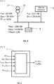
- the figure 1 represents in the form of a block diagram, an electrical installation 1 comprising a variable energy source 42, an electrical load 3, an energy distribution network 2, at least one electrical energy converter 4 and a control device of the converter 5.
- the variable source of energy 42 is a source of transformation of a durable energy such as the energy delivered by the sun into energy generally called renewable such as solar energy, wind, tidal, etc.
- the variable energy source 42 is connected to the electrical energy converter 4 whose role is to transform the energy supplied by the variable source 42 into electrical energy that can be consumed by the electrical load 3.
- the electrical load 3 is connected to the converter 4 in the electrical installation 1.
- the electrical installation 1 is connected to an electrical energy distribution network 2 at a connection point 21, the electrical load 3 and the converter 4 are therefore connected to the electrical distribution network. energy 2.
- the electrical energy converter 4 supplies a first active power Pinv and a first reactive power Qinv.
- the power level supplied by the converter 4 can be controlled: the control device 5, connected to said converter 4, sends a supply instruction to the converter 4 of active power CmdPinv and reactive, CmdQinv, so that the converter 4 provides the first active power Pinv and the first reactive power Qinv requested.
- the electrical load 3 consumes a second active power Pload and a second reactive power Qload.
- the electrical load 3 represents one or more electrical items of equipment which can be put into operation or out of operation as required.
- the second active power Pload and the second reactive power Qload therefore vary over time.
- the electrical installation 1 preferably operates in self-consumption mode, that is to say that the variable source of energy 42 supplies energy to the electrical load 3.
- the variable source of energy 42 is not always dimensioned to supply all the energy consumed by the electric charge 3 and, on the other hand, the supply of energy by the energy source 42 is made variable by the presence of clouds, the variation of the wind force, the season, etc. and, consequently, in the case where the variable source of energy 42 is not able to supply all the energy required by the electrical load 3, the distribution network of energy 2 provides, in addition, a third active power Pnet and a third reactive power Qnet.
- the process which is the subject of the invention takes place cyclically: it processes the input data to provide output data such as a commanded reactive power value Cmd_Pinv and a commanded reactive power value Cmd_Qinv intended for the converter 4
- the converter 4 sets the supply of the first active powers Pinv and reactive Qinv updated as a function of the values of the active and reactive powers ordered, respectively Cmd_Pinv and Cmd_Qinv.
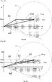
- the first apparent power Sinv must have its origin at the end of the vector representing the third apparent power Snet supplied by the distribution network and its end at the end of the vector representing the second apparent power Sload.
- the figure 4A represents a first Fresnel diagram in order to illustrate a drawback of the prior art.
- the second apparent power Sload is entered in a target power factor Ztarg zone corresponding to a power factor greater than the target power factor PFtarg.
- the first apparent power Sinv is zero and the distribution network 2 must supply the third apparent power Snet equal to the second apparent power Sload.
- the PFnet network power factor remains higher than the target PFtarg power factor.
- variable energy source 42 produces a first apparent power Sinv, which is purely reactive, as shown in figure 4A , the third apparent power Snet decreases in amplitude but the network power factor PFnet leaves the Ztarg zone, which corresponds to a power factor lower than the target power factor PFtarg.
- This configuration is unfavorable because, although the third apparent power Snet supplied by the distribution network is reduced, the energy production by the variable energy source 42 will be penalized because of a poor network power factor PFnet.
- the figure 4B represents a second Fresnel diagram in order to illustrate the method for determining the first active power Pinv and the first reactive power Qinv which the converter must supply according to the second active power Pload and the second reactive power Qload, so that the PFnet network power factor is greater than or equal to a predetermined PFtarg target power factor. Since the network power factor PFnet must be greater than or equal to the target power factor PFtarg, the vector representative of the third apparent power Snet must be located in the target power factor area Ztarg and, at worst case, aligned in a direction corresponding to the target power factor PFtarg as shown in figure 4B . The end of the vector representative of the first apparent power Sinv is located at the end of the vector representative of the second apparent power Sload.
- the converter 4 supplies a first apparent power Sinv in relation to the energy supplied by the variable energy source 42.
- the first apparent power Sinv cannot therefore be increased
- the first active power Pinv and the first reactive power Qinv are controllable in order to provide the first apparent power Sinv with a converter power factor, PFinv, controllable.
- the origin of the vector representing the first apparent power Sinv on the figure 4B can therefore rotate on a circle C around the end of said vector Sinv.
- the vector representative of the first apparent power Sinv must have its origin at the point of intersection between the circle C and, in the worst case, the direction corresponding to the target power factor PFtarg.
- the determination of the first apparent power Sinv represented on the figure 4B is the solution which minimizes the third active power Pnet supplied by the distribution network 2 or maximizes the first active power Pinv supplied by the converter 4.
- This solution is particularly interesting since the network power factor PFnet is equal to the target power factor PFtarg and therefore no penalty is applied to the electrical installation 1.
- the third active power Pnet supplied by the distribution network 2 being minimized, the cost of the energy supplied by the distribution network 2 will be also minimized.
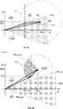
- a converter 4 having no energy storage means, or having limited storage means can be used.
- the first active power Pinv and the first reactive power Qinv can be controlled, but the converter power factor PFinv must be greater than or equal to a predefined minimum power factor PFinv_min.
- the power factor of the converter PFinv can thus be controlled only in a zone of converter power factor Zinv greater than or equal to the minimum power factor PFinv_min, for example equal to 0.8.
- the figure 4C represents a third Fresnel diagram to illustrate the process for determining the first active power Pinv and the first reactive power Qinv to be supplied by the converter 4 as a function of the second active power Pload and the second reactive power Qload, when the power factor of the converter PFinv is limited to the area power factor converter Zinv.
- the origin of the vector representing the first apparent power Sinv on the figure 4C cannot rotate on circle C outside the Zinv converter power factor area.
- the most favorable power factor of the PFinv converter will therefore be the minimum power factor PFinv_min.
- the third active power Pnet supplied by the distribution network 2 will be minimized and the network power factor PFnet will be closer to the target power factor PFtarg, the penalties linked to a bad power factor will be minimized.
- the manager of said distribution network 2 can impose a supply of a third predefined minimum active power Pnet_min, for example, contractually.
- the first active power Pinv supplied by the converter 4 is less than or equal to the difference between the second active power Pload consumed by the load and the minimum minimum active power Pnet_min supplied by the electric power distribution network 2: Pinv ⁇ Pload - Pnet_min.
- the representative vector of third apparent power Snet is formed by the component of the third active power Pnet equal to the minimum power Pnet_min. Said vector is aligned in a direction corresponding to the target power factor PFtarg.
- the second apparent power Sload is the vectorial compound of the second active power Pload and the second reactive power Qload.
- the end of the vector representative of the first apparent power Sinv is located at the end of the vector representative of the second apparent power Sload.
- the vector representative of the first apparent power Sinv must have its origin at the end of the vector representative of the third apparent power Snet supplied by the network of distribution when said end is situated inside the circle C. It is possible to optimize the supply of energy by the converter 4 by increasing the first reactive power Qinv, within the limit where the power factor of the converter PFinv remains in the Zinv converter power factor area, which increases the PFnet network power factor. In the opposite case, that is to say when the end of the vector representative of the third apparent power Snet is outside of the circle C, the constraint of supplying a third minimum active power Pnet_min does not take place d since the converter 4 is not able to produce enough energy, the configuration is identical to the second Fresnel diagram described in figure 4B .
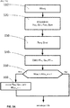
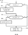
- the figure 5A and 5B represent a flowchart of the method according to the invention.
- the method begins with a step 110 of acquiring the value of the target power factor PFtarg.
- the value of said power factor can be stored in memory in the converter control device 5 or entered via a man-machine interface.
- the process continues with a step 120 of acquiring the values of the first active power Pinv and of the first reactive power Qinv by means of a measurement or by communication of data between the converter 4 and the device for controlling the converter 5.
- a measurement of the third active power Pnet and of the third reactive power Qnet is also carried out during step 120.
- the method continues with an evaluation sequence 130 of the second active and reactive powers Pload and Qload consumed by the load. 3.
- the method may have predetermined values of the second active and reactive powers Pload and Qload stored in memory in the control device of the converter 5 or entered via a man-machine interface.
- Pload Pnet + Pinv, the values of Pnet and Pinv having been measured in step 120 above.
- Qload Qnet + Qinv.
- a first determination of the values of the first active power Pinv and of the first reactive power Qinv necessary for the network power factor PFnet to be greater than or equal to a target power factor PFtarg is carried out during a step 140, for example by means of a vector calculation described in figure 4B .
- a comparison step 150 when the converter power factor PFinv is greater than the minimum power factor PFinv_min, i.e. the converter power factor PFinv is located in the converter power factor area Zinv, then the converter can supply the first active power Pinv and the first reactive power Qinv determined in the first determination step 140 and the process continues with a step 170 of verifying the value of the active power Pnet supplied by the network of distribution.
- the converter power factor, PFinv is less than the minimum power factor PFinv_min, then the converter cannot supply the first active and reactive powers Pinv, Qinv determined by the method, and, in in this case, the method continues with a step 160 during which the converter supplies the first reactive power Qinv as large as possible, as shown in figure 4C .
- the converter provides maximum energy by improving the PFnet network power factor as much as possible.
- the process continues at step 170 of verification.
- the distribution network manager 2 can impose a supply of a third minimum active power Pnet_min within the framework of the operation of the electrical installation 1 in self-consumption mode.
- the method verifies that the active power Pnet supplied by the distribution network is greater than or equal to the third minimum active power Pnet_min. If this is the case, the first active power Pinv and of the first reactive power Qinv determined by the method can be supplied by the converter and the process continues at a step 210 of controlling the converter 4.
- the method comprises a step 180 of calculating the first active power Pinv which must be supplied by the converter 4 so that the network provides the third minimum active power Pnet_min.
- Pinv Pload - Pnet_min.
- the first reactive power Qinv is maximized so that the third reactive power Qnet is minimum, as shown in figure 4D .
- a determination of the converter power factor PFinv is also carried out in step 180.
- a comparison of said converter power factor PFinv with the minimum power factor PFinv_min is carried out during a step 190. If the converter power factor PFinv is greater than the minimum power factor PFinv_min, the values of the first active power Pinv and of the first reactive power Qinv to be supplied by the converter having been determined are sent respectively in the form of control parameters CmdPinv and CmdQinv to the converter 4 during of the converter control step 210 4.
- the first reactive power Qinv is defined as a function of the first active power Pinv previously evaluated and the minimum converter power factor PFinv_min as shown in figure 4E .
- the process continues with the step 210 of controlling the converter 4.
- the process takes place cyclically, with a period preferably between 1 minute and 10 minutes.
- the process can also take place on detection of a variation of the first active power Pinv, reactive Qinv or apparent Sinv, supplied by the converter 4, or else on detection of variation of the active power Pload, reactive Qload or apparent Sload consumed by the load 3.
- the control circuit 53 includes circuits for executing the method as described above and for transmitting to the converter 4 the control parameters CmdPinv and CmdQinv corresponding to the first active power Pinv and to the first reactive power Qinv which the converter 4 must supply.
- control device 5 can be installed in the electrical energy converter 4 in order to reduce the cost of said device.
- the first measurement circuit 51 is arranged to carry out at least two measurements, preferably the third active power Pnet and the third reactive power Qnet. Said first measurement circuit 51 can also carry out the measurement of the third apparent power Snet and of the network power factor PFnet knowing that the third active power Pnet and the third reactive power Qnet can easily be calculated from the third apparent power Snet and of the PFnet network power factor and vice versa. It is the same for the second measurement circuit 52. More generally, it is possible to reconstruct any measurement of active, reactive, apparent power or of the power factor knowing at least two among these four types of measurement .
- variable energy source 42 consists of at least one photovoltaic panel. It can also consist of at least one generator driven by a wind turbine or by the energy of the tides.
- the converter 4 can be formed from the parallel connection of several converters, each converter being connected to one or more variable sources of energy.
- the measurement of the first active power Pinv and of the first reactive power Qinv corresponds respectively to a measurement of the active power and of the reactive power supplied by all the converters and the control parameters CmdPinv and CmdQinv are applied distributed to all the converters so that all the converters provide the first active power Pinv and the first reactive power Qinv requested.
- the method and the device for optimizing the supply of energy from the variable source of electrical energy 42 in the electrical installation 1 are particularly advantageous to use in the context of the production of electrical energy in a self-consumption mode. Indeed, the device only requires knowledge of the value of the target power factor PFtarg and, possibly, the value of the third minimum active power Pnet_min, these two parameters being imposed by the manager of the electrical distribution network 2.
- the installation Electric 1 behaves like an adaptive device, capable of optimizing its energy production by providing a PFnet network power factor high enough not to generate a penalty.
Landscapes
- Engineering & Computer Science (AREA)
- Power Engineering (AREA)
- Supply And Distribution Of Alternating Current (AREA)
- Control Of Electric Motors In General (AREA)
- Inverter Devices (AREA)
Applications Claiming Priority (1)
| Application Number | Priority Date | Filing Date | Title |
|---|---|---|---|
| FR1873415A FR3091054B1 (fr) | 2018-12-19 | 2018-12-19 | Procédé pour optimiser la fourniture d’énergie d’une source d’énergie électrique dans une installation électrique et dispositif pour la mise en œuvre d’un tel procédé |
Publications (2)
| Publication Number | Publication Date |
|---|---|
| EP3672012A1 true EP3672012A1 (de) | 2020-06-24 |
| EP3672012B1 EP3672012B1 (de) | 2021-07-28 |
Family
ID=67001884
Family Applications (1)
| Application Number | Title | Priority Date | Filing Date |
|---|---|---|---|
| EP19211986.5A Active EP3672012B1 (de) | 2018-12-19 | 2019-11-28 | Verfahren zur optimierung der energieversorgung aus einer elektrischen energiequelle in einer elektrischen anlage und vorrichtung zur durchführung eines solchen verfahrens |
Country Status (5)
| Country | Link |
|---|---|
| US (1) | US11398730B2 (de) |
| EP (1) | EP3672012B1 (de) |
| CN (1) | CN111342497B (de) |
| ES (1) | ES2885818T3 (de) |
| FR (1) | FR3091054B1 (de) |
Families Citing this family (1)
| Publication number | Priority date | Publication date | Assignee | Title |
|---|---|---|---|---|
| CN112803892B (zh) * | 2021-01-15 | 2022-07-26 | 广东电网有限责任公司佛山供电局 | 一种低压光伏发电故障的诊断算法 |
Citations (9)
| Publication number | Priority date | Publication date | Assignee | Title |
|---|---|---|---|---|
| FR2823381A1 (fr) * | 2001-04-05 | 2002-10-11 | Electricite De France | Procede et installation de regulation de la tension d'un dispositif decentralise de production d'energie electrique raccorde a un reseau de distribution |
| WO2007060328A1 (fr) | 2005-11-25 | 2007-05-31 | Schneider Electric Industries Sas | Méthode et dispositif de régulation pour un dispositif de production décentralisée d'énergie, et installation comportant au moins deux dispositifs de production dotés dudit dispositif de régulation |
| WO2012125278A2 (en) | 2011-03-14 | 2012-09-20 | Sunpower Corporation | Automatic voltage regulation for photovoltaic systems |
| EP2582002A2 (de) * | 2011-10-12 | 2013-04-17 | Electricité de France | Spannungsregulierungsverfahren in einem Netz, das dezentralisierte Quellen umfasst |
| CN103412207B (zh) * | 2013-07-11 | 2015-08-05 | 华北电力大学(保定) | 基于负序电流注入的光伏并网逆变器孤岛检测方法 |
| US20150270712A1 (en) * | 2014-03-18 | 2015-09-24 | Kabushiki Kaisha Toshiba | Controlling apparatus, power converting apparatus and controlling system |
| EP3029797A1 (de) | 2014-12-04 | 2016-06-08 | ABB Technology AG | Vorrichtung zur Umwandlung und optimierten Verbrauchsverwaltung von Strom aus erneuerbaren Energie |
| US20170214337A1 (en) | 2016-01-21 | 2017-07-27 | Eaton Corporation | System and method for controlling the operating area of an inverter coupled to an alternative energy source |
| US9806665B2 (en) | 2011-06-27 | 2017-10-31 | Sunpower Corporation | Methods and apparatus for controlling operation of photovoltaic power plants |
Family Cites Families (12)
| Publication number | Priority date | Publication date | Assignee | Title |
|---|---|---|---|---|
| US8406019B2 (en) * | 2008-09-15 | 2013-03-26 | General Electric Company | Reactive power compensation in solar power system |
| US8693228B2 (en) * | 2009-02-19 | 2014-04-08 | Stefan Matan | Power transfer management for local power sources of a grid-tied load |
| BR112012003700A2 (pt) * | 2009-08-19 | 2016-04-05 | Skytron Energy Gmbh | regulamento para usina elétrica |
| KR101135284B1 (ko) * | 2010-11-15 | 2012-04-12 | (주)인텍에프에이 | 충전장치를 채용하고 무효전력 제어기능을 갖는 다중기능 전력변환 장치 및 방법 |
| US8857083B2 (en) | 2012-04-17 | 2014-10-14 | Lev Volftsun | Message in a bottle |
| CN202712872U (zh) * | 2012-05-17 | 2013-01-30 | 阳光电源股份有限公司 | 并网逆变电源与防逆流、无功补偿控制器及系统 |
| KR101484064B1 (ko) * | 2013-10-02 | 2015-01-19 | (주) 세스 | 신재생 에너지의 전력제어장치 |
| CN106164681A (zh) * | 2014-02-14 | 2016-11-23 | 智能动力股份有限公司 | 具有定位在客户现场处的无功伏安控制器的计量器/电压调节器 |
| US10139800B2 (en) | 2015-03-05 | 2018-11-27 | Regents Of The University Of Minnesota | Decentralized optimal dispatch of photovoltaic inverters in power distribution systems |
| US10483759B2 (en) * | 2016-04-07 | 2019-11-19 | Alencon Acquisition Co., Llc | Integrated multi-mode large-scale electric power support system for an electrical grid |
| CN108736509A (zh) * | 2017-04-25 | 2018-11-02 | 全球能源互联网研究院 | 一种主动配电网多源协调优化控制方法及系统 |
| CN107658909A (zh) * | 2017-09-26 | 2018-02-02 | 湖南大学 | 一种含光伏接入的中低压配电网电压抬升抑制方法 |
-
2018
- 2018-12-19 FR FR1873415A patent/FR3091054B1/fr not_active Expired - Fee Related
-
2019
- 2019-11-28 EP EP19211986.5A patent/EP3672012B1/de active Active
- 2019-11-28 ES ES19211986T patent/ES2885818T3/es active Active
- 2019-12-09 US US16/707,055 patent/US11398730B2/en active Active
- 2019-12-16 CN CN201911292298.7A patent/CN111342497B/zh active Active
Patent Citations (9)
| Publication number | Priority date | Publication date | Assignee | Title |
|---|---|---|---|---|
| FR2823381A1 (fr) * | 2001-04-05 | 2002-10-11 | Electricite De France | Procede et installation de regulation de la tension d'un dispositif decentralise de production d'energie electrique raccorde a un reseau de distribution |
| WO2007060328A1 (fr) | 2005-11-25 | 2007-05-31 | Schneider Electric Industries Sas | Méthode et dispositif de régulation pour un dispositif de production décentralisée d'énergie, et installation comportant au moins deux dispositifs de production dotés dudit dispositif de régulation |
| WO2012125278A2 (en) | 2011-03-14 | 2012-09-20 | Sunpower Corporation | Automatic voltage regulation for photovoltaic systems |
| US9806665B2 (en) | 2011-06-27 | 2017-10-31 | Sunpower Corporation | Methods and apparatus for controlling operation of photovoltaic power plants |
| EP2582002A2 (de) * | 2011-10-12 | 2013-04-17 | Electricité de France | Spannungsregulierungsverfahren in einem Netz, das dezentralisierte Quellen umfasst |
| CN103412207B (zh) * | 2013-07-11 | 2015-08-05 | 华北电力大学(保定) | 基于负序电流注入的光伏并网逆变器孤岛检测方法 |
| US20150270712A1 (en) * | 2014-03-18 | 2015-09-24 | Kabushiki Kaisha Toshiba | Controlling apparatus, power converting apparatus and controlling system |
| EP3029797A1 (de) | 2014-12-04 | 2016-06-08 | ABB Technology AG | Vorrichtung zur Umwandlung und optimierten Verbrauchsverwaltung von Strom aus erneuerbaren Energie |
| US20170214337A1 (en) | 2016-01-21 | 2017-07-27 | Eaton Corporation | System and method for controlling the operating area of an inverter coupled to an alternative energy source |
Also Published As
| Publication number | Publication date |
|---|---|
| EP3672012B1 (de) | 2021-07-28 |
| CN111342497B (zh) | 2024-11-01 |
| US20200203950A1 (en) | 2020-06-25 |
| CN111342497A (zh) | 2020-06-26 |
| FR3091054A1 (fr) | 2020-06-26 |
| US11398730B2 (en) | 2022-07-26 |
| ES2885818T3 (es) | 2021-12-15 |
| FR3091054B1 (fr) | 2021-04-30 |
Similar Documents
| Publication | Publication Date | Title |
|---|---|---|
| Ray et al. | A robust firefly–swarm hybrid optimization for frequency control in wind/PV/FC based microgrid | |
| FR2844890A1 (fr) | Circuit de conditionnement pour une source de puissance au point de puissance maximum, generateur solaire et procede de conditionnement | |
| FR2462053A1 (fr) | Procede en vue de controler le flux de courant entre une pile electrochimique et une grille de puissance | |
| WO2013164249A1 (fr) | Dispositif de controle non-lineaire d'un convertisseur dc/dc pour application au transport de courant hvdc | |
| EP0129492A2 (de) | Verfahren und System zum Verbinden synchronischer oder asynchronischer dreiphasiger Netze mittels veränderlicher Blindstromimpedanzen | |
| FR2996032A1 (fr) | Procede de determination d'une prevision de la puissance electrique fournie par une installation de fourniture d'energie electrique | |
| FR2961035A1 (fr) | Dispositif de connexion matricielle pour panneaux photovoltaiques et/ou eoliennes | |
| FR2884804A1 (fr) | Dispositf source de secours electrique dispose sur un aeronef | |
| EP2237387B1 (de) | Power supply system and charging control method for electrochemical generators | |
| EP3672012B1 (de) | Verfahren zur optimierung der energieversorgung aus einer elektrischen energiequelle in einer elektrischen anlage und vorrichtung zur durchführung eines solchen verfahrens | |
| EP2347492B1 (de) | System und verfahren zum steuern mindestens eines spannungsumrichters mit mehreren zellen in reihe | |
| US11228277B2 (en) | Method and device for detecting a maximum system power output of a photovoltaic system | |
| EP2963611B1 (de) | Kontrollverfahren der elektrischen leistung, die von mindestens zwei stromquellen in ein stromnetz eingespeist wird, und entsprechendes elektrisches system | |
| Dahmane et al. | Power management strategy based on weather prediction for hybrid stand-Alone system | |
| FR3131474A1 (fr) | Procédé de commande d’une puissance fournie a un réseau électrique, mettant en œuvre un modèle de centrale | |
| US9851737B1 (en) | Computing an operating parameter of a unified power flow controller | |
| WO2019097183A1 (fr) | Dispositif de controle d'un terminal pour la compensation d'une perturbation en tension | |
| EP2158657B1 (de) | Steuersystem und verfahren für eine tcsc in einem elektrischen energietransportnetz insbesondere unter verwendung eines sliding-modes-ansatzes | |
| US11437817B2 (en) | Method and device for driving an electricity production assembly, and associated production assembly | |
| EP3017480B1 (de) | Simulationsschaltung eines alternierenden elektrischen gitters und steuerungsverfahren dafür | |
| EP4322362A2 (de) | Vorrichtung und verfahren zur steuerung der spannung von mikroarrays | |
| FR3131473A1 (fr) | Procédé de commande d’une puissance fournie a un réseau électrique, avec contrôleur d’hybridation | |
| WO1999063639A1 (fr) | Systeme de compensation des harmoniques dans un reseau electrique | |
| EP3273565B1 (de) | Verfahren zur rückgewinnung von überschüssiger energie in einem kraftwerk, das elektrische energie erzeugt | |
| FR3149149A1 (fr) | Contrôle d’une puissance injectée par un module de production d’énergie renouvelable dans un micro-réseau électrique par pilotage en fréquence d’un système de stockage d’énergie électrique |
Legal Events
| Date | Code | Title | Description |
|---|---|---|---|
| PUAI | Public reference made under article 153(3) epc to a published international application that has entered the european phase |
Free format text: ORIGINAL CODE: 0009012 |
|
| STAA | Information on the status of an ep patent application or granted ep patent |
Free format text: STATUS: THE APPLICATION HAS BEEN PUBLISHED |
|
| AK | Designated contracting states |
Kind code of ref document: A1 Designated state(s): AL AT BE BG CH CY CZ DE DK EE ES FI FR GB GR HR HU IE IS IT LI LT LU LV MC MK MT NL NO PL PT RO RS SE SI SK SM TR |
|
| AX | Request for extension of the european patent |
Extension state: BA ME |
|
| STAA | Information on the status of an ep patent application or granted ep patent |
Free format text: STATUS: REQUEST FOR EXAMINATION WAS MADE |
|
| 17P | Request for examination filed |
Effective date: 20210112 |
|
| RBV | Designated contracting states (corrected) |
Designated state(s): AL AT BE BG CH CY CZ DE DK EE ES FI FR GB GR HR HU IE IS IT LI LT LU LV MC MK MT NL NO PL PT RO RS SE SI SK SM TR |
|
| GRAP | Despatch of communication of intention to grant a patent |
Free format text: ORIGINAL CODE: EPIDOSNIGR1 |
|
| STAA | Information on the status of an ep patent application or granted ep patent |
Free format text: STATUS: GRANT OF PATENT IS INTENDED |
|
| RIC1 | Information provided on ipc code assigned before grant |
Ipc: H02J 3/38 20060101AFI20210325BHEP Ipc: H02J 3/48 20060101ALI20210325BHEP Ipc: H02J 3/50 20060101ALI20210325BHEP |
|
| INTG | Intention to grant announced |
Effective date: 20210416 |
|
| GRAS | Grant fee paid |
Free format text: ORIGINAL CODE: EPIDOSNIGR3 |
|
| GRAA | (expected) grant |
Free format text: ORIGINAL CODE: 0009210 |
|
| STAA | Information on the status of an ep patent application or granted ep patent |
Free format text: STATUS: THE PATENT HAS BEEN GRANTED |
|
| AK | Designated contracting states |
Kind code of ref document: B1 Designated state(s): AL AT BE BG CH CY CZ DE DK EE ES FI FR GB GR HR HU IE IS IT LI LT LU LV MC MK MT NL NO PL PT RO RS SE SI SK SM TR |
|
| REG | Reference to a national code |
Ref country code: GB Ref legal event code: FG4D Free format text: NOT ENGLISH |
|
| REG | Reference to a national code |
Ref country code: CH Ref legal event code: EP |
|
| REG | Reference to a national code |
Ref country code: AT Ref legal event code: REF Ref document number: 1415577 Country of ref document: AT Kind code of ref document: T Effective date: 20210815 |
|
| REG | Reference to a national code |
Ref country code: IE Ref legal event code: FG4D Free format text: LANGUAGE OF EP DOCUMENT: FRENCH |
|
| REG | Reference to a national code |
Ref country code: DE Ref legal event code: R096 Ref document number: 602019006435 Country of ref document: DE |
|
| REG | Reference to a national code |
Ref country code: LT Ref legal event code: MG9D |
|
| REG | Reference to a national code |
Ref country code: SE Ref legal event code: TRGR |
|
| REG | Reference to a national code |
Ref country code: NL Ref legal event code: MP Effective date: 20210728 |
|
| REG | Reference to a national code |
Ref country code: ES Ref legal event code: FG2A Ref document number: 2885818 Country of ref document: ES Kind code of ref document: T3 Effective date: 20211215 Ref country code: AT Ref legal event code: MK05 Ref document number: 1415577 Country of ref document: AT Kind code of ref document: T Effective date: 20210728 |
|
| PG25 | Lapsed in a contracting state [announced via postgrant information from national office to epo] |
Ref country code: RS Free format text: LAPSE BECAUSE OF FAILURE TO SUBMIT A TRANSLATION OF THE DESCRIPTION OR TO PAY THE FEE WITHIN THE PRESCRIBED TIME-LIMIT Effective date: 20210728 Ref country code: LT Free format text: LAPSE BECAUSE OF FAILURE TO SUBMIT A TRANSLATION OF THE DESCRIPTION OR TO PAY THE FEE WITHIN THE PRESCRIBED TIME-LIMIT Effective date: 20210728 Ref country code: BG Free format text: LAPSE BECAUSE OF FAILURE TO SUBMIT A TRANSLATION OF THE DESCRIPTION OR TO PAY THE FEE WITHIN THE PRESCRIBED TIME-LIMIT Effective date: 20211028 Ref country code: AT Free format text: LAPSE BECAUSE OF FAILURE TO SUBMIT A TRANSLATION OF THE DESCRIPTION OR TO PAY THE FEE WITHIN THE PRESCRIBED TIME-LIMIT Effective date: 20210728 Ref country code: HR Free format text: LAPSE BECAUSE OF FAILURE TO SUBMIT A TRANSLATION OF THE DESCRIPTION OR TO PAY THE FEE WITHIN THE PRESCRIBED TIME-LIMIT Effective date: 20210728 Ref country code: FI Free format text: LAPSE BECAUSE OF FAILURE TO SUBMIT A TRANSLATION OF THE DESCRIPTION OR TO PAY THE FEE WITHIN THE PRESCRIBED TIME-LIMIT Effective date: 20210728 Ref country code: NL Free format text: LAPSE BECAUSE OF FAILURE TO SUBMIT A TRANSLATION OF THE DESCRIPTION OR TO PAY THE FEE WITHIN THE PRESCRIBED TIME-LIMIT Effective date: 20210728 Ref country code: NO Free format text: LAPSE BECAUSE OF FAILURE TO SUBMIT A TRANSLATION OF THE DESCRIPTION OR TO PAY THE FEE WITHIN THE PRESCRIBED TIME-LIMIT Effective date: 20211028 Ref country code: PT Free format text: LAPSE BECAUSE OF FAILURE TO SUBMIT A TRANSLATION OF THE DESCRIPTION OR TO PAY THE FEE WITHIN THE PRESCRIBED TIME-LIMIT Effective date: 20211129 |
|
| PG25 | Lapsed in a contracting state [announced via postgrant information from national office to epo] |
Ref country code: PL Free format text: LAPSE BECAUSE OF FAILURE TO SUBMIT A TRANSLATION OF THE DESCRIPTION OR TO PAY THE FEE WITHIN THE PRESCRIBED TIME-LIMIT Effective date: 20210728 Ref country code: LV Free format text: LAPSE BECAUSE OF FAILURE TO SUBMIT A TRANSLATION OF THE DESCRIPTION OR TO PAY THE FEE WITHIN THE PRESCRIBED TIME-LIMIT Effective date: 20210728 Ref country code: GR Free format text: LAPSE BECAUSE OF FAILURE TO SUBMIT A TRANSLATION OF THE DESCRIPTION OR TO PAY THE FEE WITHIN THE PRESCRIBED TIME-LIMIT Effective date: 20211029 |
|
| PG25 | Lapsed in a contracting state [announced via postgrant information from national office to epo] |
Ref country code: DK Free format text: LAPSE BECAUSE OF FAILURE TO SUBMIT A TRANSLATION OF THE DESCRIPTION OR TO PAY THE FEE WITHIN THE PRESCRIBED TIME-LIMIT Effective date: 20210728 |
|
| REG | Reference to a national code |
Ref country code: DE Ref legal event code: R097 Ref document number: 602019006435 Country of ref document: DE |
|
| PG25 | Lapsed in a contracting state [announced via postgrant information from national office to epo] |
Ref country code: SM Free format text: LAPSE BECAUSE OF FAILURE TO SUBMIT A TRANSLATION OF THE DESCRIPTION OR TO PAY THE FEE WITHIN THE PRESCRIBED TIME-LIMIT Effective date: 20210728 Ref country code: SK Free format text: LAPSE BECAUSE OF FAILURE TO SUBMIT A TRANSLATION OF THE DESCRIPTION OR TO PAY THE FEE WITHIN THE PRESCRIBED TIME-LIMIT Effective date: 20210728 Ref country code: RO Free format text: LAPSE BECAUSE OF FAILURE TO SUBMIT A TRANSLATION OF THE DESCRIPTION OR TO PAY THE FEE WITHIN THE PRESCRIBED TIME-LIMIT Effective date: 20210728 Ref country code: EE Free format text: LAPSE BECAUSE OF FAILURE TO SUBMIT A TRANSLATION OF THE DESCRIPTION OR TO PAY THE FEE WITHIN THE PRESCRIBED TIME-LIMIT Effective date: 20210728 Ref country code: CZ Free format text: LAPSE BECAUSE OF FAILURE TO SUBMIT A TRANSLATION OF THE DESCRIPTION OR TO PAY THE FEE WITHIN THE PRESCRIBED TIME-LIMIT Effective date: 20210728 Ref country code: AL Free format text: LAPSE BECAUSE OF FAILURE TO SUBMIT A TRANSLATION OF THE DESCRIPTION OR TO PAY THE FEE WITHIN THE PRESCRIBED TIME-LIMIT Effective date: 20210728 |
|
| PLBE | No opposition filed within time limit |
Free format text: ORIGINAL CODE: 0009261 |
|
| STAA | Information on the status of an ep patent application or granted ep patent |
Free format text: STATUS: NO OPPOSITION FILED WITHIN TIME LIMIT |
|
| PG25 | Lapsed in a contracting state [announced via postgrant information from national office to epo] |
Ref country code: MC Free format text: LAPSE BECAUSE OF FAILURE TO SUBMIT A TRANSLATION OF THE DESCRIPTION OR TO PAY THE FEE WITHIN THE PRESCRIBED TIME-LIMIT Effective date: 20210728 |
|
| 26N | No opposition filed |
Effective date: 20220429 |
|
| PG25 | Lapsed in a contracting state [announced via postgrant information from national office to epo] |
Ref country code: LU Free format text: LAPSE BECAUSE OF NON-PAYMENT OF DUE FEES Effective date: 20211128 Ref country code: BE Free format text: LAPSE BECAUSE OF NON-PAYMENT OF DUE FEES Effective date: 20211130 |
|
| REG | Reference to a national code |
Ref country code: BE Ref legal event code: MM Effective date: 20211130 |
|
| PG25 | Lapsed in a contracting state [announced via postgrant information from national office to epo] |
Ref country code: IE Free format text: LAPSE BECAUSE OF NON-PAYMENT OF DUE FEES Effective date: 20211128 |
|
| PG25 | Lapsed in a contracting state [announced via postgrant information from national office to epo] |
Ref country code: CY Free format text: LAPSE BECAUSE OF FAILURE TO SUBMIT A TRANSLATION OF THE DESCRIPTION OR TO PAY THE FEE WITHIN THE PRESCRIBED TIME-LIMIT Effective date: 20210728 |
|
| REG | Reference to a national code |
Ref country code: CH Ref legal event code: PL |
|
| PG25 | Lapsed in a contracting state [announced via postgrant information from national office to epo] |
Ref country code: LI Free format text: LAPSE BECAUSE OF NON-PAYMENT OF DUE FEES Effective date: 20221130 Ref country code: HU Free format text: LAPSE BECAUSE OF FAILURE TO SUBMIT A TRANSLATION OF THE DESCRIPTION OR TO PAY THE FEE WITHIN THE PRESCRIBED TIME-LIMIT; INVALID AB INITIO Effective date: 20191128 Ref country code: CH Free format text: LAPSE BECAUSE OF NON-PAYMENT OF DUE FEES Effective date: 20221130 |
|
| PG25 | Lapsed in a contracting state [announced via postgrant information from national office to epo] |
Ref country code: MK Free format text: LAPSE BECAUSE OF FAILURE TO SUBMIT A TRANSLATION OF THE DESCRIPTION OR TO PAY THE FEE WITHIN THE PRESCRIBED TIME-LIMIT Effective date: 20210728 |
|
| PG25 | Lapsed in a contracting state [announced via postgrant information from national office to epo] |
Ref country code: MT Free format text: LAPSE BECAUSE OF FAILURE TO SUBMIT A TRANSLATION OF THE DESCRIPTION OR TO PAY THE FEE WITHIN THE PRESCRIBED TIME-LIMIT Effective date: 20210728 |
|
| PGFP | Annual fee paid to national office [announced via postgrant information from national office to epo] |
Ref country code: IT Payment date: 20241125 Year of fee payment: 6 Ref country code: ES Payment date: 20241218 Year of fee payment: 6 |
|
| PGFP | Annual fee paid to national office [announced via postgrant information from national office to epo] |
Ref country code: SE Payment date: 20241126 Year of fee payment: 6 |
|
| PG25 | Lapsed in a contracting state [announced via postgrant information from national office to epo] |
Ref country code: TR Free format text: LAPSE BECAUSE OF FAILURE TO SUBMIT A TRANSLATION OF THE DESCRIPTION OR TO PAY THE FEE WITHIN THE PRESCRIBED TIME-LIMIT Effective date: 20210728 |
|
| PGFP | Annual fee paid to national office [announced via postgrant information from national office to epo] |
Ref country code: DE Payment date: 20251126 Year of fee payment: 7 |
|
| PGFP | Annual fee paid to national office [announced via postgrant information from national office to epo] |
Ref country code: GB Payment date: 20251125 Year of fee payment: 7 |
|
| PGFP | Annual fee paid to national office [announced via postgrant information from national office to epo] |
Ref country code: FR Payment date: 20251124 Year of fee payment: 7 |