EP3671946A1 - Battery module having improved cooling structure - Google Patents
Battery module having improved cooling structure Download PDFInfo
- Publication number
- EP3671946A1 EP3671946A1 EP18897735.9A EP18897735A EP3671946A1 EP 3671946 A1 EP3671946 A1 EP 3671946A1 EP 18897735 A EP18897735 A EP 18897735A EP 3671946 A1 EP3671946 A1 EP 3671946A1
- Authority
- EP
- European Patent Office
- Prior art keywords
- spacer
- cell stack
- battery module
- base plate
- battery
- Prior art date
- Legal status (The legal status is an assumption and is not a legal conclusion. Google has not performed a legal analysis and makes no representation as to the accuracy of the status listed.)
- Granted
Links
Images


Classifications
-
- H—ELECTRICITY
- H01—ELECTRIC ELEMENTS
- H01M—PROCESSES OR MEANS, e.g. BATTERIES, FOR THE DIRECT CONVERSION OF CHEMICAL ENERGY INTO ELECTRICAL ENERGY
- H01M10/00—Secondary cells; Manufacture thereof
- H01M10/60—Heating or cooling; Temperature control
- H01M10/62—Heating or cooling; Temperature control specially adapted for specific applications
- H01M10/625—Vehicles
-
- H—ELECTRICITY
- H01—ELECTRIC ELEMENTS
- H01M—PROCESSES OR MEANS, e.g. BATTERIES, FOR THE DIRECT CONVERSION OF CHEMICAL ENERGY INTO ELECTRICAL ENERGY
- H01M10/00—Secondary cells; Manufacture thereof
- H01M10/60—Heating or cooling; Temperature control
- H01M10/65—Means for temperature control structurally associated with the cells
- H01M10/655—Solid structures for heat exchange or heat conduction
- H01M10/6556—Solid parts with flow channel passages or pipes for heat exchange
-
- B—PERFORMING OPERATIONS; TRANSPORTING
- B60—VEHICLES IN GENERAL
- B60L—PROPULSION OF ELECTRICALLY-PROPELLED VEHICLES; SUPPLYING ELECTRIC POWER FOR AUXILIARY EQUIPMENT OF ELECTRICALLY-PROPELLED VEHICLES; ELECTRODYNAMIC BRAKE SYSTEMS FOR VEHICLES IN GENERAL; MAGNETIC SUSPENSION OR LEVITATION FOR VEHICLES; MONITORING OPERATING VARIABLES OF ELECTRICALLY-PROPELLED VEHICLES; ELECTRIC SAFETY DEVICES FOR ELECTRICALLY-PROPELLED VEHICLES
- B60L50/00—Electric propulsion with power supplied within the vehicle
- B60L50/50—Electric propulsion with power supplied within the vehicle using propulsion power supplied by batteries or fuel cells
- B60L50/60—Electric propulsion with power supplied within the vehicle using propulsion power supplied by batteries or fuel cells using power supplied by batteries
- B60L50/64—Constructional details of batteries specially adapted for electric vehicles
-
- B—PERFORMING OPERATIONS; TRANSPORTING
- B60—VEHICLES IN GENERAL
- B60L—PROPULSION OF ELECTRICALLY-PROPELLED VEHICLES; SUPPLYING ELECTRIC POWER FOR AUXILIARY EQUIPMENT OF ELECTRICALLY-PROPELLED VEHICLES; ELECTRODYNAMIC BRAKE SYSTEMS FOR VEHICLES IN GENERAL; MAGNETIC SUSPENSION OR LEVITATION FOR VEHICLES; MONITORING OPERATING VARIABLES OF ELECTRICALLY-PROPELLED VEHICLES; ELECTRIC SAFETY DEVICES FOR ELECTRICALLY-PROPELLED VEHICLES
- B60L58/00—Methods or circuit arrangements for monitoring or controlling batteries or fuel cells, specially adapted for electric vehicles
- B60L58/10—Methods or circuit arrangements for monitoring or controlling batteries or fuel cells, specially adapted for electric vehicles for monitoring or controlling batteries
- B60L58/24—Methods or circuit arrangements for monitoring or controlling batteries or fuel cells, specially adapted for electric vehicles for monitoring or controlling batteries for controlling the temperature of batteries
- B60L58/26—Methods or circuit arrangements for monitoring or controlling batteries or fuel cells, specially adapted for electric vehicles for monitoring or controlling batteries for controlling the temperature of batteries by cooling
-
- H—ELECTRICITY
- H01—ELECTRIC ELEMENTS
- H01M—PROCESSES OR MEANS, e.g. BATTERIES, FOR THE DIRECT CONVERSION OF CHEMICAL ENERGY INTO ELECTRICAL ENERGY
- H01M10/00—Secondary cells; Manufacture thereof
- H01M10/60—Heating or cooling; Temperature control
- H01M10/61—Types of temperature control
- H01M10/613—Cooling or keeping cold
-
- H—ELECTRICITY
- H01—ELECTRIC ELEMENTS
- H01M—PROCESSES OR MEANS, e.g. BATTERIES, FOR THE DIRECT CONVERSION OF CHEMICAL ENERGY INTO ELECTRICAL ENERGY
- H01M10/00—Secondary cells; Manufacture thereof
- H01M10/60—Heating or cooling; Temperature control
- H01M10/64—Heating or cooling; Temperature control characterised by the shape of the cells
- H01M10/647—Prismatic or flat cells, e.g. pouch cells
-
- H—ELECTRICITY
- H01—ELECTRIC ELEMENTS
- H01M—PROCESSES OR MEANS, e.g. BATTERIES, FOR THE DIRECT CONVERSION OF CHEMICAL ENERGY INTO ELECTRICAL ENERGY
- H01M10/00—Secondary cells; Manufacture thereof
- H01M10/60—Heating or cooling; Temperature control
- H01M10/65—Means for temperature control structurally associated with the cells
- H01M10/656—Means for temperature control structurally associated with the cells characterised by the type of heat-exchange fluid
- H01M10/6567—Liquids
-
- H—ELECTRICITY
- H01—ELECTRIC ELEMENTS
- H01M—PROCESSES OR MEANS, e.g. BATTERIES, FOR THE DIRECT CONVERSION OF CHEMICAL ENERGY INTO ELECTRICAL ENERGY
- H01M50/00—Constructional details or processes of manufacture of the non-active parts of electrochemical cells other than fuel cells, e.g. hybrid cells
- H01M50/20—Mountings; Secondary casings or frames; Racks, modules or packs; Suspension devices; Shock absorbers; Transport or carrying devices; Holders
- H01M50/204—Racks, modules or packs for multiple batteries or multiple cells
- H01M50/207—Racks, modules or packs for multiple batteries or multiple cells characterised by their shape
- H01M50/211—Racks, modules or packs for multiple batteries or multiple cells characterised by their shape adapted for pouch cells
-
- H—ELECTRICITY
- H01—ELECTRIC ELEMENTS
- H01M—PROCESSES OR MEANS, e.g. BATTERIES, FOR THE DIRECT CONVERSION OF CHEMICAL ENERGY INTO ELECTRICAL ENERGY
- H01M50/00—Constructional details or processes of manufacture of the non-active parts of electrochemical cells other than fuel cells, e.g. hybrid cells
- H01M50/20—Mountings; Secondary casings or frames; Racks, modules or packs; Suspension devices; Shock absorbers; Transport or carrying devices; Holders
- H01M50/249—Mountings; Secondary casings or frames; Racks, modules or packs; Suspension devices; Shock absorbers; Transport or carrying devices; Holders specially adapted for aircraft or vehicles, e.g. cars or trains
-
- H—ELECTRICITY
- H01—ELECTRIC ELEMENTS
- H01M—PROCESSES OR MEANS, e.g. BATTERIES, FOR THE DIRECT CONVERSION OF CHEMICAL ENERGY INTO ELECTRICAL ENERGY
- H01M50/00—Constructional details or processes of manufacture of the non-active parts of electrochemical cells other than fuel cells, e.g. hybrid cells
- H01M50/20—Mountings; Secondary casings or frames; Racks, modules or packs; Suspension devices; Shock absorbers; Transport or carrying devices; Holders
- H01M50/258—Modular batteries; Casings provided with means for assembling
-
- H—ELECTRICITY
- H01—ELECTRIC ELEMENTS
- H01M—PROCESSES OR MEANS, e.g. BATTERIES, FOR THE DIRECT CONVERSION OF CHEMICAL ENERGY INTO ELECTRICAL ENERGY
- H01M50/00—Constructional details or processes of manufacture of the non-active parts of electrochemical cells other than fuel cells, e.g. hybrid cells
- H01M50/20—Mountings; Secondary casings or frames; Racks, modules or packs; Suspension devices; Shock absorbers; Transport or carrying devices; Holders
- H01M50/262—Mountings; Secondary casings or frames; Racks, modules or packs; Suspension devices; Shock absorbers; Transport or carrying devices; Holders with fastening means, e.g. locks
-
- H—ELECTRICITY
- H01—ELECTRIC ELEMENTS
- H01M—PROCESSES OR MEANS, e.g. BATTERIES, FOR THE DIRECT CONVERSION OF CHEMICAL ENERGY INTO ELECTRICAL ENERGY
- H01M50/00—Constructional details or processes of manufacture of the non-active parts of electrochemical cells other than fuel cells, e.g. hybrid cells
- H01M50/20—Mountings; Secondary casings or frames; Racks, modules or packs; Suspension devices; Shock absorbers; Transport or carrying devices; Holders
- H01M50/271—Lids or covers for the racks or secondary casings
-
- H—ELECTRICITY
- H01—ELECTRIC ELEMENTS
- H01M—PROCESSES OR MEANS, e.g. BATTERIES, FOR THE DIRECT CONVERSION OF CHEMICAL ENERGY INTO ELECTRICAL ENERGY
- H01M50/00—Constructional details or processes of manufacture of the non-active parts of electrochemical cells other than fuel cells, e.g. hybrid cells
- H01M50/20—Mountings; Secondary casings or frames; Racks, modules or packs; Suspension devices; Shock absorbers; Transport or carrying devices; Holders
- H01M50/289—Mountings; Secondary casings or frames; Racks, modules or packs; Suspension devices; Shock absorbers; Transport or carrying devices; Holders characterised by spacing elements or positioning means within frames, racks or packs
-
- H—ELECTRICITY
- H01—ELECTRIC ELEMENTS
- H01M—PROCESSES OR MEANS, e.g. BATTERIES, FOR THE DIRECT CONVERSION OF CHEMICAL ENERGY INTO ELECTRICAL ENERGY
- H01M2220/00—Batteries for particular applications
- H01M2220/20—Batteries in motive systems, e.g. vehicle, ship, plane
-
- Y—GENERAL TAGGING OF NEW TECHNOLOGICAL DEVELOPMENTS; GENERAL TAGGING OF CROSS-SECTIONAL TECHNOLOGIES SPANNING OVER SEVERAL SECTIONS OF THE IPC; TECHNICAL SUBJECTS COVERED BY FORMER USPC CROSS-REFERENCE ART COLLECTIONS [XRACs] AND DIGESTS
- Y02—TECHNOLOGIES OR APPLICATIONS FOR MITIGATION OR ADAPTATION AGAINST CLIMATE CHANGE
- Y02E—REDUCTION OF GREENHOUSE GAS [GHG] EMISSIONS, RELATED TO ENERGY GENERATION, TRANSMISSION OR DISTRIBUTION
- Y02E60/00—Enabling technologies; Technologies with a potential or indirect contribution to GHG emissions mitigation
- Y02E60/10—Energy storage using batteries
Definitions
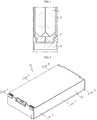
- FIG. 1 a conventional battery module structure is shown. If a plurality of pouch-type cells 1 are stacked by using a plurality of frames 2, in the conventional battery module structure, plate-shaped cooling fins 3 are applied on the outer surfaces of each of the pair of pouch-type cells 1, thereby increasing the cooling efficiency.
- the cooling fin 3 usually made of a metal material is interposed between the pouch-type cells 1 facing each other to configure the battery module, the contact heat resistance is inevitably very large due to the difference in material between the cooling fin 3 and the surface of the pouch-type cell 1. Also, only with the cooling method that depends on the conductivity of the metal, sufficient cooling is achieved in a situation where a large amount of heat is generated.
- the present disclosure is designed to solve the problems of the related art, and therefore the present disclosure is directed to providing a battery module, which adopts a cooling structure capable of allowing direct contact between a cooling medium and battery cells so that the battery module may be efficiently cooled even when the amount of heat increases by applying a battery module with a high capacity and/or a high output.
- An adhesive may be interposed between the cell stack and the spacer so that the cooling medium is not leaked between the cell stack and the spacer.
- the spacer may include a first spacer provided at one side of the base plate in a longitudinal direction; a second spacer provided at the other side of the base plate in the longitudinal direction; and a third spacer spaced apart from the first spacer and the second spacer and provided between the first spacer and the second spacer.
- the supply tube may be connected to a first spacer channel formed through the inside of the first spacer, and the discharge tube may be connected to a second spacer channel formed through the inside of the second spacer.
- a battery pack which is implemented by connecting a plurality of battery modules according to an embodiment of the present disclosure.
- a vehicle comprising the battery pack according to an embodiment of the present disclosure.
- the battery module since a battery module with a cooling structure capable of direct contact between a cooling medium and battery cells is provided, the battery module may be efficiently cooled even when the amount of heat increases by applying a battery module with a high capacity and/or a high output, thereby improving the performance of the battery module. Moreover, it is possible to prevent safety accidents such as ignition and explosion of the battery cells due to the temperature rise.
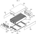
- FIG. 2 is a perspective view showing an appearance of a battery module according to an embodiment of the present disclosure
- FIG. 3 is an exploded perspective view showing the battery module according to an embodiment of the present disclosure.
- a battery module 10 includes a cell stack 100 and a module housing 20 for accommodating the cell stack 100. Also, the module housing 20 includes a lower housing 200, a pair of side housings 300, a pair of front and rear housings 400, and an upper housing 500.
- the cell stack 100 is prepared by stacking a plurality of battery cells 110.
- the battery cell 110 used herein is not particularly limited as long as it is a secondary battery capable of charging and discharging.
- the battery cell 110 may be a pouch-type battery cell.
- Each of the battery cells 110 may have a pair of electrode leads 111 extending to one side and the other side.
- the electrode leads 111 include a positive electrode lead and a negative electrode lead.
- the stacked battery cells 110 may be firmly fixed and sealed by an adhesive or the like so that a cooling medium such as an insulating oil, which is in contact with a lower portion of the cell stack 100, is not able to penetrate through the space between the battery cells 110 of the cell stack 100.
- the electrode leads 111 may be arranged or connected such that the battery cells 110 of the cell stack 100 are connected in series, in parallel, or both in series and in parallel.
- the lower housing 200 includes a base plate 210 for entirely covering a lower surface of the cell stack 100, a spacer 220 for partially covering the lower surface of the cell stack 100, a supply tube 230 connected to the spacer 220 to supply a cooling medium such as an insulating oil for cooling the battery module 10, and a discharge tube 240 connected to the spacer 220 to discharge the cooling medium to the outside.
- a base plate 210 for entirely covering a lower surface of the cell stack 100
- a spacer 220 for partially covering the lower surface of the cell stack 100
- a supply tube 230 connected to the spacer 220 to supply a cooling medium such as an insulating oil for cooling the battery module 10
- a discharge tube 240 connected to the spacer 220 to discharge the cooling medium to the outside.
- the spacer 220 is interposed between the cell stack 100 and the base plate 210 and forms an empty space between the cell stack 100 and the base plate 210 by partially covering the lower surface of the cell stack 100. That is, the empty space corresponds to a closed space surrounded by the cell stack 100, the spacer 220, and the base plate 210.
- the supply tube 230 is connected to the spacer 220 from a front portion of the battery module 10 to supply a cooling medium into the spacer 220.
- the cooling medium supplied into the spacer 220 is supplied to the empty space between the cell stack 100 and the base plate 210 through a channel formed inside the spacer 220.
- the discharge tube 240 is connected to the spacer 220 from a rear portion of the battery module 10 to discharge the cooling medium flowing through the empty space and the inside of the spacer 220 to the outside.
- the pair of side housings 300 respectively cover both sides of the cell stack 100 and face wide surfaces of the battery cells 110 disposed on outermost sides among the battery cells 110 of the cell stack 100.
- the pair of side housings 300 may press the cell stack 100 at both sides thereof to prevent an empty space from being created between the battery cells 110 of the cell stack 100.
- the bus bar frame 410 is coupled to the cell stack 100 from the front or rear portion of the cell stack 100.
- the electrode leads 111 are inserted into the bus bar frame 410 to facilitate the bending work of the electrode lead 111 for electrical connection between the battery cells 110. That is, the electrode leads 111 are inserted through insert slits formed at the bus bar frame 410 and then bent so that the adjacent electrode leads 111 are coupled to each other by welding or the like.
- the upper housing 500 may include a sensor assembly 510 disposed at an upper portion of the cell stack 100 and electrically connected to the electrode leads 111 inserted and bent through the bus bar frame 410, and a top plate 520 coupled to an upper portion of the sensor assembly 510 to form an outermost layer of the upper housing 500.
- FIG. 4 is a diagram showing that a cooling medium flows on a base plate of the battery module according to an embodiment of the present disclosure
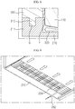
- FIG. 5 is a cross-sectioned view, taken along the lines A-A' and B-B' of FIG. 2
- FIG. 6 is an enlarged view showing one side end of FIG. 5
- FIG. 7 is a cross-sectioned view, taken along the lines C-C' of FIG. 2
- FIG. 8 is an enlarged view showing one side end of FIG. 7 .
- a coupling unit 211 having a coupling groove G formed at a predetermined depth in a downward direction from the top is provided at both side ends of the base plate 210.
- a coupling protrusion 310 protruding downward is provided at a lower end of the side housing 300, and the coupling protrusion 310 is inserted and fixed into the coupling groove G, thereby fixing the side housing 300 to the base plate 210.
- the coupling unit 211 has a protrusion P protruding toward the inside of the battery module.
- the protrusion P extends to contact the battery cell 110 disposed at the outermost side to prevent that a gap is created between the base plate 210 and the cell stack 100 to leak the cooling medium.
- an adhesive is interposed between the cell stack 100 and the spacer 220 so that the cooling medium such as an insulating oil is not leaked between the cell stack 100 and the spacer 220.
- the adhesive not only couples and fixes the cell stack 100 and the spacer 220 to each other but also functions as a gasket.
- the spacer 220 may be formed with a plurality of unit spacers spaced apart from each other.
- the spacer 220 may include a first spacer 221 provided at one end of the base plate 210 in a longitudinal direction, a second spacer 222 provided at the other end of the base plate 210 in the longitudinal direction, and a third spacer 223 spaced apart from the first spacer 221 and the second spacer 222 and provided between the first spacer 221 and the second spacer 222.
- the supply tube 230 may be connected to the first spacer 221 from the front portion of the battery module 10 to supply the cooling medium to the battery module 10.
- the discharge tube 240 may be connected to the second spacer 222 from the rear portion of the battery module 10 to cool the battery module 10 and discharge the heated cooling medium to the outside.
- the supply tube 230 is connected to a plurality of first spacer channels 221a provided through the inside of the first spacer 221 to supply the cooling medium. That is, the supply tube 230 extends along the extension direction of the first spacer 221 disposed across the width of the base plate 210, namely the longitudinal direction of the first spacer 221, and is individually connected to the plurality of first spacer channels 221a to supply the cooling medium to all of the first spacer channels 221a.
- the discharge tube 240 is connected to a plurality of second spacer channels 222a provided through the inside of the second spacer 222, similar to the supply tube 230 described above, to discharge the cooling medium. That is, the discharge tube 240 extends along the extension direction of the second spacer 222 disposed across the width of the base plate 210, namely the longitudinal direction of the second spacer 222, and individually connected to the plurality of second spacer channels 222a to discharge the introduced cooling medium through all of the second spacer channels 222a.
- the third spacer 223 may include a plurality of third spacer channels 223a formed through the inside of the third spacer 223 to allow the cooling medium flowing into the inner space S1 of the battery module 10 through the first spacer 221 to pass toward the second spacer 222.
- FIG. 9 is a diagram showing a supply tube and a spacer, implemented in a different way from the supply tube and the spacer depicted in FIG. 4 .
- the battery module 10 has a function with an improved sealing property to solve the leakage of the cooling medium, which may occur when a liquid cooling medium such as a cooling water and an insulating oil is in direct contact with the battery cell 110, thereby enhancing the reliability of the product.
Landscapes
- Chemical & Material Sciences (AREA)
- Chemical Kinetics & Catalysis (AREA)
- Electrochemistry (AREA)
- General Chemical & Material Sciences (AREA)
- Engineering & Computer Science (AREA)
- Manufacturing & Machinery (AREA)
- Sustainable Energy (AREA)
- Life Sciences & Earth Sciences (AREA)
- Sustainable Development (AREA)
- Power Engineering (AREA)
- Transportation (AREA)
- Mechanical Engineering (AREA)
- Aviation & Aerospace Engineering (AREA)
- Battery Mounting, Suspending (AREA)
- Secondary Cells (AREA)
Abstract
Description
- The present disclosure relates to a battery module with an improved cooling structure, and more particularly, to a battery module with an improved cooling efficiency, which uses an insulating oil for cooling and has a cooling structure for allowing the insulating oil to directly contact battery cells.
- The present application claims priority to Korean Patent Application No.
10-2017-0180560 filed on December 27, 2017 - Secondary batteries commercially used at present includes nickel-cadmium batteries, nickel-hydrogen batteries, nickel-zinc batteries, and lithium secondary batteries. Among them, the lithium secondary batteries are highly spotlighted due to substantially no memory effect to ensure free charging and discharging, very low self-discharge rate and high energy density, compared to nickel-based secondary batteries.
- The lithium secondary battery mainly uses a lithium-based oxide and a carbonaceous material as a positive electrode active material and a negative electrode active material, respectively. The lithium secondary battery includes an electrode assembly in which a positive electrode plate and a negative electrode plate coated with a positive electrode active material and a negative electrode active material are disposed with a separator being interposed therebetween, and an exterior, namely a battery case, for hermetically accommodating the electrode assembly along with an electrolyte.
- Generally, the lithium secondary battery may be classified into a can-type secondary battery in which the electrode assembly is included in a metal can and a pouch-type secondary battery in which the electrode assembly is included in a pouch made of aluminum laminate sheets, depending on the shape of the exterior.
- Recently, secondary batteries have been widely used not only in small-sized devices such as portable electronic devices but also in medium-sized or large-sized devices such as vehicles and power storage systems. When used in the medium-sized or large-sized devices, a large number of secondary batteries are electrically connected to increase capacity and power. In particular, pouch-type cells are widely used for the medium-sized or large-sized devices because of they may be easily stacked.
- However, the pouch-type cell is generally packaged in the battery case made of a laminate sheet of aluminum and polymer resin, and thus its mechanical stiffness is not large. Thus, when the battery module including a plurality of pouch-type cells is configured, a frame is often used to protect the secondary batteries from external impact, prevent shaking thereof, and facilitate stacking thereof.
- The frame may be called in different ways such as a cartridge. In many cases, the frame has a rectangular shape having an empty center portion, and at this time, four sides of the frame surround the outer circumference of the pouch-type cell. In addition, a plurality of frames are stacked to configure the battery module, and the pouch-type cells may be placed in the empty space inside the frame when the frames are stacked.
- Meanwhile, referring to
FIG. 1 , a conventional battery module structure is shown. If a plurality of pouch-type cells 1 are stacked by using a plurality offrames 2, in the conventional battery module structure, plate-shaped cooling fins 3 are applied on the outer surfaces of each of the pair of pouch-type cells 1, thereby increasing the cooling efficiency. - The secondary battery may be used in high temperature environments such as summer, and the secondary battery may also generate heat from themselves. At this time, if a plurality of secondary batteries are stacked on each other, the temperature of the secondary batteries may become higher. If the temperature is higher than a proper temperature, the performance of the secondary batteries may deteriorate, and in severe cases, explosion or ignition may occur. Thus, when the battery module is configured, the
cooling fins 3 are applied to contact the surface of the pouch-type cell 1, and thecooling fins 3 are brought into contact with acooling plate 4 located therebelow to prevent the overall temperature of the battery module from rising. This configuration is used frequently. - However, if the
cooling fin 3 usually made of a metal material is interposed between the pouch-type cells 1 facing each other to configure the battery module, the contact heat resistance is inevitably very large due to the difference in material between thecooling fin 3 and the surface of the pouch-type cell 1. Also, only with the cooling method that depends on the conductivity of the metal, sufficient cooling is achieved in a situation where a large amount of heat is generated. - Thus, there is an urgent need to develop a battery module structure using a cooling method capable of reducing contact thermal resistance and allowing heat to be emitted more efficiently, compared to a simple thermal conduction method.
- The present disclosure is designed to solve the problems of the related art, and therefore the present disclosure is directed to providing a battery module, which adopts a cooling structure capable of allowing direct contact between a cooling medium and battery cells so that the battery module may be efficiently cooled even when the amount of heat increases by applying a battery module with a high capacity and/or a high output.
- However, the technical problem to be solved by the present disclosure is not limited to the above, and other objects not mentioned herein will be understood from the following description by those skilled in the art.
- In one aspect of the present disclosure, there is provided a battery module, comprising: a cell stack formed by stacking a plurality of battery cells; and a module housing configured to accommodate the cell stack and having a lower housing, a pair of side housing, a pair of front and rear housings and an upper housing for respectively covering a lower portion, both side portions, front and rear portions and an upper portion of the cell stack, wherein the lower housing includes: a base plate configured to entirely cover a lower surface of the cell stack; a spacer interposed between the cell stack and the base plate to partially cover the lower surface of the cell stack so that an empty space is formed between the cell stack and the base plate; a supply tube connected to the spacer to supply a cooling medium to the empty space through the inside of the spacer; and a discharge tube connected to the spacer to discharge the cooling medium flowing in the empty space and the spacer to the outside.
- An adhesive may be interposed between the cell stack and the spacer so that the cooling medium is not leaked between the cell stack and the spacer.
- Coupling units respectively having coupling grooves may be provided at both side ends of the base plate, a coupling protrusion protruding downward may be formed at a lower end of the side housing, and the coupling protrusion may be inserted and fixed into the coupling groove to fix the side housing to the base plate.
- The coupling unit may have a protrusion protruding toward an inner side of the battery module, and the protrusion may extend to contact a battery cell located at an outermost side of the cell stack to prevent the cooling medium from being leaked between the base plate and the cell stack.
- The spacer may include a first spacer provided at one side of the base plate in a longitudinal direction; a second spacer provided at the other side of the base plate in the longitudinal direction; and a third spacer spaced apart from the first spacer and the second spacer and provided between the first spacer and the second spacer.
- The supply tube may be connected to a first spacer channel formed through the inside of the first spacer, and the discharge tube may be connected to a second spacer channel formed through the inside of the second spacer.
- The third spacer may have a third spacer channel formed through the inside thereof so that the cooling medium supplied through the first spacer flows toward the second spacer.
- Meanwhile, in another aspect of the present disclosure, there is also provided a battery pack, which is implemented by connecting a plurality of battery modules according to an embodiment of the present disclosure. Also, in another aspect of the present disclosure, there is also provided a vehicle, comprising the battery pack according to an embodiment of the present disclosure.
- According to an embodiment of the present disclosure, since a battery module with a cooling structure capable of direct contact between a cooling medium and battery cells is provided, the battery module may be efficiently cooled even when the amount of heat increases by applying a battery module with a high capacity and/or a high output, thereby improving the performance of the battery module. Moreover, it is possible to prevent safety accidents such as ignition and explosion of the battery cells due to the temperature rise.
- The accompanying drawings illustrate a preferred embodiment of the present disclosure and together with the foregoing disclosure, serve to provide further understanding of the technical features of the present disclosure, and thus, the present disclosure is not construed as being limited to the drawing.
-
FIG. 1 is a diagram showing a cooling structure applied to a conventional battery module. -
FIG. 2 is a perspective view showing an appearance of a battery module according to an embodiment of the present disclosure. -
FIG. 3 is an exploded perspective view showing the battery module according to an embodiment of the present disclosure. -
FIG. 4 is a diagram showing that a cooling medium flows on a base plate of the battery module according to an embodiment of the present disclosure. -
FIG. 5 is a cross-sectioned view, taken along the lines A-A' and B-B' ofFIG. 2 . -
FIG. 6 is an enlarged view showing one side end ofFIG. 5 . -
FIG. 7 is a cross-sectioned view, taken along the lines C-C' ofFIG. 2 . -
FIG. 8 is an enlarged view showing one side end ofFIG. 7 . -
FIG. 9 is a diagram showing a supply tube and a spacer, implemented in a different way from the supply tube and the spacer depicted inFIG. 4 . - Hereinafter, preferred embodiments of the present disclosure will be described in detail with reference to the accompanying drawings. Prior to the description, it should be understood that the terms used in the specification and the appended claims should not be construed as limited to general and dictionary meanings, but interpreted based on the meanings and concepts corresponding to technical aspects of the present disclosure on the basis of the principle that the inventor is allowed to define terms appropriately for the best explanation. Therefore, the description proposed herein is just a preferable example for the purpose of illustrations only, not intended to limit the scope of the disclosure, so it should be understood that other equivalents and modifications could be made thereto without departing from the scope of the disclosure.
- First, components of a
battery module 10 according to an embodiment of the present disclosure will be described briefly with reference toFIGS. 2 and3 . -
FIG. 2 is a perspective view showing an appearance of a battery module according to an embodiment of the present disclosure, andFIG. 3 is an exploded perspective view showing the battery module according to an embodiment of the present disclosure. - Referring to
FIGS. 2 and3 , abattery module 10 according to an embodiment of the present disclosure includes acell stack 100 and amodule housing 20 for accommodating thecell stack 100. Also, themodule housing 20 includes alower housing 200, a pair ofside housings 300, a pair of front andrear housings 400, and anupper housing 500. - The
cell stack 100 is prepared by stacking a plurality ofbattery cells 110. Thebattery cell 110 used herein is not particularly limited as long as it is a secondary battery capable of charging and discharging. For example, thebattery cell 110 may be a pouch-type battery cell. - Each of the
battery cells 110 may have a pair of electrode leads 111 extending to one side and the other side. The electrode leads 111 include a positive electrode lead and a negative electrode lead. As explained later, the stackedbattery cells 110 may be firmly fixed and sealed by an adhesive or the like so that a cooling medium such as an insulating oil, which is in contact with a lower portion of thecell stack 100, is not able to penetrate through the space between thebattery cells 110 of thecell stack 100. - In addition, the electrode leads 111 may be arranged or connected such that the
battery cells 110 of thecell stack 100 are connected in series, in parallel, or both in series and in parallel. - The
lower housing 200 includes abase plate 210 for entirely covering a lower surface of thecell stack 100, aspacer 220 for partially covering the lower surface of thecell stack 100, asupply tube 230 connected to thespacer 220 to supply a cooling medium such as an insulating oil for cooling thebattery module 10, and adischarge tube 240 connected to thespacer 220 to discharge the cooling medium to the outside. - The
spacer 220 is interposed between thecell stack 100 and thebase plate 210 and forms an empty space between thecell stack 100 and thebase plate 210 by partially covering the lower surface of thecell stack 100. That is, the empty space corresponds to a closed space surrounded by thecell stack 100, thespacer 220, and thebase plate 210. - The
supply tube 230 is connected to thespacer 220 from a front portion of thebattery module 10 to supply a cooling medium into thespacer 220. The cooling medium supplied into thespacer 220 is supplied to the empty space between thecell stack 100 and thebase plate 210 through a channel formed inside thespacer 220. - The
discharge tube 240 is connected to thespacer 220 from a rear portion of thebattery module 10 to discharge the cooling medium flowing through the empty space and the inside of thespacer 220 to the outside. - The pair of
side housings 300 respectively cover both sides of thecell stack 100 and face wide surfaces of thebattery cells 110 disposed on outermost sides among thebattery cells 110 of thecell stack 100. The pair ofside housings 300 may press thecell stack 100 at both sides thereof to prevent an empty space from being created between thebattery cells 110 of thecell stack 100. - The pair of front and
rear housings 400 may include abus bar frame 410, aninsulation cover 420, and front andrear plates 430, respectively. - The
bus bar frame 410 is coupled to thecell stack 100 from the front or rear portion of thecell stack 100. The electrode leads 111 are inserted into thebus bar frame 410 to facilitate the bending work of the electrode lead 111 for electrical connection between thebattery cells 110. That is, the electrode leads 111 are inserted through insert slits formed at thebus bar frame 410 and then bent so that the adjacent electrode leads 111 are coupled to each other by welding or the like. - The
insulation cover 420 is a component provided to prevent the electrode leads 111, which are coupled to each other by inserted into thebus bar frame 410 and bent but should not be in contact with each other, from contacting each other. Theinsulation cover 420 is coupled onto thebus bar frame 410 to prevent a short caused by an external factor. - The front and
rear plates 430 are components coupled onto theinsulation cover 420 and serve to protect internal components such as thecell stack 100, thebus bar frame 410, and theinsulation cover 420. - The
upper housing 500 may include asensor assembly 510 disposed at an upper portion of thecell stack 100 and electrically connected to the electrode leads 111 inserted and bent through thebus bar frame 410, and atop plate 520 coupled to an upper portion of thesensor assembly 510 to form an outermost layer of theupper housing 500. - Next, the specific cooling structure of the battery module according to an embodiment of the present disclosure will be described with reference to
FIGS. 4 to 8 along withFIGS. 2 and3 . -
FIG. 4 is a diagram showing that a cooling medium flows on a base plate of the battery module according to an embodiment of the present disclosure,FIG. 5 is a cross-sectioned view, taken along the lines A-A' and B-B' ofFIG. 2 , andFIG. 6 is an enlarged view showing one side end ofFIG. 5 . Also,FIG. 7 is a cross-sectioned view, taken along the lines C-C' ofFIG. 2 , andFIG. 8 is an enlarged view showing one side end ofFIG. 7 . - Referring to
FIGS. 4 to 8 along withFIGS. 2 and3 , acoupling unit 211 having a coupling groove G formed at a predetermined depth in a downward direction from the top is provided at both side ends of thebase plate 210. Meanwhile, acoupling protrusion 310 protruding downward is provided at a lower end of theside housing 300, and thecoupling protrusion 310 is inserted and fixed into the coupling groove G, thereby fixing theside housing 300 to thebase plate 210. - The
coupling unit 211 has a protrusion P protruding toward the inside of the battery module. The protrusion P extends to contact thebattery cell 110 disposed at the outermost side to prevent that a gap is created between thebase plate 210 and thecell stack 100 to leak the cooling medium. - Also, an adhesive is interposed between the
cell stack 100 and thespacer 220 so that the cooling medium such as an insulating oil is not leaked between thecell stack 100 and thespacer 220. The adhesive not only couples and fixes thecell stack 100 and thespacer 220 to each other but also functions as a gasket. - Meanwhile, the
spacer 220 may be formed with a plurality of unit spacers spaced apart from each other. For example, thespacer 220 may include afirst spacer 221 provided at one end of thebase plate 210 in a longitudinal direction, asecond spacer 222 provided at the other end of thebase plate 210 in the longitudinal direction, and athird spacer 223 spaced apart from thefirst spacer 221 and thesecond spacer 222 and provided between thefirst spacer 221 and thesecond spacer 222. - However, even though three unit spacers are depicted in the figures, the number of unit spacers is not limited thereto, and more unit spacers may be provided. That is, one or more unit spacers spaced apart from each other may be provided between the
first spacer 221 and thesecond spacer 222. However, hereinafter, for convenience of explanation, it will be described that three unit spacers are provided. - The
supply tube 230 may be connected to thefirst spacer 221 from the front portion of thebattery module 10 to supply the cooling medium to thebattery module 10. Likewise, thedischarge tube 240 may be connected to thesecond spacer 222 from the rear portion of thebattery module 10 to cool thebattery module 10 and discharge the heated cooling medium to the outside. - That is, the
supply tube 230 is connected to a plurality offirst spacer channels 221a provided through the inside of thefirst spacer 221 to supply the cooling medium. That is, thesupply tube 230 extends along the extension direction of thefirst spacer 221 disposed across the width of thebase plate 210, namely the longitudinal direction of thefirst spacer 221, and is individually connected to the plurality offirst spacer channels 221a to supply the cooling medium to all of thefirst spacer channels 221a. - Meanwhile, the
discharge tube 240 is connected to a plurality ofsecond spacer channels 222a provided through the inside of thesecond spacer 222, similar to thesupply tube 230 described above, to discharge the cooling medium. That is, thedischarge tube 240 extends along the extension direction of thesecond spacer 222 disposed across the width of thebase plate 210, namely the longitudinal direction of thesecond spacer 222, and individually connected to the plurality ofsecond spacer channels 222a to discharge the introduced cooling medium through all of thesecond spacer channels 222a. - Meanwhile, the
third spacer 223 may include a plurality ofthird spacer channels 223a formed through the inside of thethird spacer 223 to allow the cooling medium flowing into the inner space S1 of thebattery module 10 through thefirst spacer 221 to pass toward thesecond spacer 222. - The
third spacer channels 223a are exposed out of thethird spacer 223 so that the space S1 between thefirst spacer 221 and thethird spacer 223 and the space S2 between thethird spacer 223 and thesecond spacer 222 are in communication with the inner space of thethird spacer 223. - That is, the cooling medium supplied to the
battery module 10 through thesupply tube 230 is discharged out of thebattery module 10 by moving through thesupply tube 230, thefirst spacer 221, the space S1, thethird spacer 223, the space S2, thesecond spacer 222, and thedischarge tube 240 in order. - Next, a battery module according to another embodiment of the present disclosure will be described with reference to
FIG. 9 . -
FIG. 9 is a diagram showing a supply tube and a spacer, implemented in a different way from the supply tube and the spacer depicted inFIG. 4 . - The battery module according to another embodiment of the present disclosure is substantially identical to the battery module of the former embodiment, even though there is a slight difference in the connection structure between the
supply tube 250 and thefirst spacer 224 and the specific configuration of thefirst spacer 224. Thus, in describing the battery module according to another embodiment of the present disclosure, features different from the former embodiment will be described in detail, and features already described in the former embodiment will not described again. - Referring to
FIG. 9 , in the battery module according to another embodiment of the present disclosure, thesupply tube 250 and thefirst spacer 224 are connected at one spot, rather than plural spots, and a channel (not shown) of thefirst spacer 224 connected to thesupply tube 250 communicates with the plurality of channels for discharging the cooling medium. - As described above, in the
battery module 10 according to the present disclosure, thespacer 220 is partially applied between thecell stack 100 and thebase plate 210, and the cooling medium is supplied into the empty spaces S1, S2 formed between thecell stack 100 and thebase plate 210 so that thecell stack 100 may be brought into direct contact with the cooling medium, thereby maximizing the cooling efficiency. - Also, the
battery module 10 according to the present disclosure has a function with an improved sealing property to solve the leakage of the cooling medium, which may occur when a liquid cooling medium such as a cooling water and an insulating oil is in direct contact with thebattery cell 110, thereby enhancing the reliability of the product. - In addition, a battery pack according to an embodiment of the present disclosure, which is implemented by electrically connecting plurality of the battery modules described above, and a vehicle having the battery pack may also exhibit excellent performance since they have the above advantages of the battery module.
- The present disclosure has been described in detail. However, it should be understood that the detailed description and specific examples, while indicating preferred embodiments of the disclosure, are given by way of illustration only, since various changes and modifications within the scope of the disclosure will become apparent to those skilled in the art from this detailed description.
Claims (9)
- A battery module, comprising:a cell stack formed by stacking a plurality of battery cells; anda module housing configured to accommodate the cell stack and having a lower housing, a pair of side housing, a pair of front and rear housings and an upper housing for respectively covering a lower portion, both side portions, front and rear portions and an upper portion of the cell stack,wherein the lower housing includes:a base plate configured to entirely cover a lower surface of the cell stack;a spacer interposed between the cell stack and the base plate to partially cover the lower surface of the cell stack so that an empty space is formed between the cell stack and the base plate;a supply tube connected to the spacer to supply a cooling medium to the empty space through the inside of the spacer; anda discharge tube connected to the spacer to discharge the cooling medium flowing in the empty space and the spacer to the outside.
- The battery module according to claim 1,
wherein an adhesive is interposed between the cell stack and the spacer so that the cooling medium is not leaked between the cell stack and the spacer. - The battery module according to claim 2,
wherein coupling units respectively having coupling grooves are provided at both side ends of the base plate, a coupling protrusion protruding downward is formed at a lower end of the side housing, and the coupling protrusion is inserted and fixed into the coupling groove to fix the side housing to the base plate. - The battery module according to claim 3,
wherein the coupling unit has a protrusion protruding toward an inner side of the battery module, and the protrusion extends to contact a battery cell located at an outermost side of the cell stack to prevent the cooling medium from being leaked between the base plate and the cell stack. - The battery module according to claim 1,
wherein the spacer includes:a first spacer provided at one side of the base plate in a longitudinal direction;a second spacer provided at the other side of the base plate in the longitudinal direction; anda third spacer spaced apart from the first spacer and the second spacer and provided between the first spacer and the second spacer. - The battery module according to claim 5,
wherein the supply tube is connected to a first spacer channel formed through the inside of the first spacer, and
wherein the discharge tube is connected to a second spacer channel formed through the inside of the second spacer. - The battery module according to claim 6,
wherein the third spacer has a third spacer channel formed through the inside thereof so that the cooling medium supplied through the first spacer flows toward the second spacer. - A battery pack, which is implemented by connecting a plurality of battery modules defined in any one of claims 1 to 7.
- A vehicle, comprising the battery pack defined in claim 8.
Applications Claiming Priority (2)
| Application Number | Priority Date | Filing Date | Title |
|---|---|---|---|
| KR1020170180560A KR102273195B1 (en) | 2017-12-27 | 2017-12-27 | Battery module with improved cooling structure |
| PCT/KR2018/015340 WO2019132290A1 (en) | 2017-12-27 | 2018-12-05 | Battery module having improved cooling structure |
Publications (3)
| Publication Number | Publication Date |
|---|---|
| EP3671946A1 true EP3671946A1 (en) | 2020-06-24 |
| EP3671946A4 EP3671946A4 (en) | 2020-11-18 |
| EP3671946B1 EP3671946B1 (en) | 2023-04-26 |
Family
ID=67067816
Family Applications (1)
| Application Number | Title | Priority Date | Filing Date |
|---|---|---|---|
| EP18897735.9A Active EP3671946B1 (en) | 2017-12-27 | 2018-12-05 | Battery module having improved cooling structure |
Country Status (9)
| Country | Link |
|---|---|
| US (1) | US11264668B2 (en) |
| EP (1) | EP3671946B1 (en) |
| JP (1) | JP7045605B2 (en) |
| KR (1) | KR102273195B1 (en) |
| CN (1) | CN110770965B (en) |
| ES (1) | ES2946145T3 (en) |
| HU (1) | HUE062188T2 (en) |
| PL (1) | PL3671946T3 (en) |
| WO (1) | WO2019132290A1 (en) |
Cited By (1)
| Publication number | Priority date | Publication date | Assignee | Title |
|---|---|---|---|---|
| EP4629416A4 (en) * | 2023-08-16 | 2026-04-15 | Lg Energy Solution Ltd | BATTERY MODULE AND BATTERY PACK SO THAT |
Families Citing this family (18)
| Publication number | Priority date | Publication date | Assignee | Title |
|---|---|---|---|---|
| KR102754904B1 (en) * | 2019-08-26 | 2025-01-13 | 주식회사 엘지에너지솔루션 | Battery module and battery pack including the same |
| KR102520590B1 (en) | 2019-10-24 | 2023-04-10 | 주식회사 엘지에너지솔루션 | Battery module and battery pack including the same |
| KR102473125B1 (en) | 2019-11-25 | 2022-11-30 | 주식회사 엘지에너지솔루션 | Battery module and battery pack including the same |
| KR102757441B1 (en) | 2019-11-26 | 2025-01-17 | 주식회사 엘지에너지솔루션 | Battery module |
| KR102888269B1 (en) * | 2019-12-03 | 2025-11-19 | 에스케이온 주식회사 | Bettery module |
| KR102364202B1 (en) * | 2020-04-14 | 2022-02-17 | 에너테크인터내셔널 주식회사 | Battery pack for electric vehicles with improved cooling performance |
| KR102821616B1 (en) * | 2020-04-28 | 2025-06-16 | 주식회사 엘지에너지솔루션 | Battery pack and device including the same |
| KR102890754B1 (en) * | 2020-04-29 | 2025-11-24 | 주식회사 엘지에너지솔루션 | Battery pack and device including the same |
| KR102890291B1 (en) * | 2020-09-21 | 2025-11-21 | 주식회사 엘지에너지솔루션 | Battery module and battery pack including the same |
| KR102930264B1 (en) | 2020-10-16 | 2026-02-23 | 주식회사 엘지에너지솔루션 | Battery pack and device including the same |
| KR102876435B1 (en) * | 2020-11-12 | 2025-10-23 | 주식회사 엘지에너지솔루션 | Battery module having a cooling structure using insulating oil, and a battery pack and vehicle comprising the same |
| KR102855973B1 (en) * | 2020-11-16 | 2025-09-04 | 주식회사 엘지에너지솔루션 | Battery module having a cooling structure using insulating oil, and a battery pack and vehicle comprising the same |
| JP7750934B2 (en) * | 2020-12-04 | 2025-10-07 | エルジー エナジー ソリューション リミテッド | Battery module and battery pack including same |
| KR102892943B1 (en) | 2021-03-22 | 2025-11-27 | 주식회사 엘지에너지솔루션 | Battery module and battery pack including the same |
| KR102862200B1 (en) * | 2021-06-08 | 2025-09-18 | 주식회사 엘지에너지솔루션 | Battery module having a cooling structure using Insulation coolant, and a battery pack and vehicle comprising the same |
| KR102862209B1 (en) * | 2021-06-08 | 2025-09-18 | 주식회사 엘지에너지솔루션 | Battery module having a cooling structure using Insulation coolant, and a battery pack and vehicle comprising the same |
| KR20230076448A (en) * | 2021-11-24 | 2023-05-31 | 주식회사 엘지에너지솔루션 | Battery module and battery pack including the same |
| CN120604381A (en) * | 2023-09-07 | 2025-09-05 | 株式会社Lg新能源 | Battery components |
Family Cites Families (22)
| Publication number | Priority date | Publication date | Assignee | Title |
|---|---|---|---|---|
| KR20060102851A (en) | 2005-03-25 | 2006-09-28 | 삼성에스디아이 주식회사 | Secondary battery module |
| US8399119B2 (en) * | 2009-08-28 | 2013-03-19 | Lg Chem, Ltd. | Battery module and method for cooling the battery module |
| EP2442383A1 (en) | 2010-10-13 | 2012-04-18 | Magna E-Car Systems GmbH & Co OG | Modular system for a battery |
| JP2013051100A (en) | 2011-08-31 | 2013-03-14 | Nissan Motor Co Ltd | Battery temperature control module |
| DE102011082199B4 (en) * | 2011-09-06 | 2021-06-10 | Robert Bosch Gmbh | Battery with temperature control unit |
| WO2013084938A1 (en) | 2011-12-09 | 2013-06-13 | 本田技研工業株式会社 | Battery cooling structure |
| KR101561121B1 (en) | 2012-11-01 | 2015-10-19 | 주식회사 엘지화학 | Middle or Large-sized Battery Pack Having Efficient Cooling Structure |
| JP2014093244A (en) | 2012-11-06 | 2014-05-19 | Nissan Motor Co Ltd | Heat transfer structure of battery module |
| JP2014220089A (en) * | 2013-05-08 | 2014-11-20 | 小島プレス工業株式会社 | Battery pack |
| KR101686583B1 (en) * | 2013-11-29 | 2016-12-14 | 주식회사 엘지화학 | Battery Module of Cartridge Stacking Structure |
| KR101589931B1 (en) | 2014-01-06 | 2016-01-29 | 희성정밀 주식회사 | Battery cooling apparatus for electric vehicle |
| KR102172846B1 (en) | 2014-02-10 | 2020-11-02 | 삼성에스디아이 주식회사 | Battery pack |
| KR101773105B1 (en) * | 2014-07-31 | 2017-08-30 | 주식회사 엘지화학 | Battery module |
| KR101678490B1 (en) * | 2014-08-22 | 2016-11-22 | 주식회사 엘지화학 | Cartridge for secondary battery and battery module including the same |
| KR101795703B1 (en) * | 2014-11-06 | 2017-11-08 | 주식회사 엘지화학 | Cartridge for secondary battery and battery module including the same |
| JP6122414B2 (en) | 2014-11-13 | 2017-04-26 | 本田技研工業株式会社 | Electric vehicle |
| KR101780037B1 (en) | 2015-04-22 | 2017-09-19 | 주식회사 엘지화학 | Cooling device for battery cell and battery module comprising the same |
| DE102015214185B4 (en) | 2015-07-27 | 2017-03-30 | Audi Ag | Battery module for a motor vehicle, module assembly and motor vehicle |
| HUE067756T2 (en) | 2015-07-27 | 2024-11-28 | Contemporary Amperex Technology Hong Kong Ltd | Battery module heat management assembly |
| KR102057620B1 (en) * | 2015-08-13 | 2019-12-19 | 주식회사 엘지화학 | Battery module |
| KR102084151B1 (en) | 2015-10-07 | 2020-03-03 | 주식회사 엘지화학 | Battery module, battery pack comprising the battery module and vehicle comprising the battery pack |
| US10147986B2 (en) * | 2015-11-03 | 2018-12-04 | Ford Global Technologies, Llc | Traction battery assembly |
-
2017
- 2017-12-27 KR KR1020170180560A patent/KR102273195B1/en active Active
-
2018
- 2018-12-05 JP JP2019568612A patent/JP7045605B2/en active Active
- 2018-12-05 WO PCT/KR2018/015340 patent/WO2019132290A1/en not_active Ceased
- 2018-12-05 HU HUE18897735A patent/HUE062188T2/en unknown
- 2018-12-05 ES ES18897735T patent/ES2946145T3/en active Active
- 2018-12-05 CN CN201880040567.8A patent/CN110770965B/en active Active
- 2018-12-05 PL PL18897735.9T patent/PL3671946T3/en unknown
- 2018-12-05 US US16/618,534 patent/US11264668B2/en active Active
- 2018-12-05 EP EP18897735.9A patent/EP3671946B1/en active Active
Cited By (1)
| Publication number | Priority date | Publication date | Assignee | Title |
|---|---|---|---|---|
| EP4629416A4 (en) * | 2023-08-16 | 2026-04-15 | Lg Energy Solution Ltd | BATTERY MODULE AND BATTERY PACK SO THAT |
Also Published As
| Publication number | Publication date |
|---|---|
| US20200168864A1 (en) | 2020-05-28 |
| PL3671946T3 (en) | 2023-07-17 |
| JP2020523756A (en) | 2020-08-06 |
| JP7045605B2 (en) | 2022-04-01 |
| CN110770965A (en) | 2020-02-07 |
| CN110770965B (en) | 2023-04-04 |
| US11264668B2 (en) | 2022-03-01 |
| KR102273195B1 (en) | 2021-07-05 |
| WO2019132290A1 (en) | 2019-07-04 |
| EP3671946A4 (en) | 2020-11-18 |
| EP3671946B1 (en) | 2023-04-26 |
| KR20190078841A (en) | 2019-07-05 |
| HUE062188T2 (en) | 2023-09-28 |
| ES2946145T3 (en) | 2023-07-13 |
Similar Documents
| Publication | Publication Date | Title |
|---|---|---|
| EP3671946B1 (en) | Battery module having improved cooling structure | |
| US20240030517A1 (en) | Battery Module Having Improved Cooling Structure | |
| US11916244B2 (en) | Battery module including partition member | |
| EP3379638B1 (en) | Battery module | |
| US9484592B2 (en) | Battery module having structure of improved stability and high cooling efficiency | |
| EP3358668B1 (en) | Battery module, battery pack and vehicle having same | |
| US8551643B2 (en) | Battery pack | |
| EP3352291A1 (en) | Battery module, battery pack comprising same, and automobile | |
| EP3276739A2 (en) | Battery module | |
| KR20230051461A (en) | Secondary Battery and Battery Module Having the Same | |
| EP3716393A1 (en) | Cooling efficiency-enhanced battery module and battery pack comprising same | |
| KR20180005456A (en) | Battery module, battery pack comprising the battery module and vehicle comprising the battery pack | |
| KR20180023699A (en) | Battery module | |
| US20220158284A1 (en) | Battery Module and Battery Pack Including the Same | |
| KR20190074796A (en) | Battery module with improved cooling efficiency | |
| EP4432446B1 (en) | Battery module, and battery pack and vehicle including the same | |
| KR20240166667A (en) | Battery Pack | |
| KR20180023637A (en) | Battery module | |
| KR20260062565A (en) | A Coolong Structure composed of cooling Plate | |
| CN117638356A (en) | Battery module |
Legal Events
| Date | Code | Title | Description |
|---|---|---|---|
| STAA | Information on the status of an ep patent application or granted ep patent |
Free format text: STATUS: THE INTERNATIONAL PUBLICATION HAS BEEN MADE |
|
| PUAI | Public reference made under article 153(3) epc to a published international application that has entered the european phase |
Free format text: ORIGINAL CODE: 0009012 |
|
| STAA | Information on the status of an ep patent application or granted ep patent |
Free format text: STATUS: REQUEST FOR EXAMINATION WAS MADE |
|
| 17P | Request for examination filed |
Effective date: 20200316 |
|
| AK | Designated contracting states |
Kind code of ref document: A1 Designated state(s): AL AT BE BG CH CY CZ DE DK EE ES FI FR GB GR HR HU IE IS IT LI LT LU LV MC MK MT NL NO PL PT RO RS SE SI SK SM TR |
|
| AX | Request for extension of the european patent |
Extension state: BA ME |
|
| A4 | Supplementary search report drawn up and despatched |
Effective date: 20201019 |
|
| RIC1 | Information provided on ipc code assigned before grant |
Ipc: H01M 10/6567 20140101ALI20201013BHEP Ipc: H01M 10/647 20140101ALI20201013BHEP Ipc: H01M 10/613 20140101ALI20201013BHEP Ipc: H01M 2/10 20060101ALI20201013BHEP Ipc: H01M 10/625 20140101ALI20201013BHEP Ipc: H01M 10/6556 20140101AFI20201013BHEP |
|
| DAV | Request for validation of the european patent (deleted) | ||
| DAX | Request for extension of the european patent (deleted) | ||
| RAP1 | Party data changed (applicant data changed or rights of an application transferred) |
Owner name: LG ENERGY SOLUTION LTD. |
|
| RAP3 | Party data changed (applicant data changed or rights of an application transferred) |
Owner name: LG ENERGY SOLUTION, LTD. |
|
| GRAP | Despatch of communication of intention to grant a patent |
Free format text: ORIGINAL CODE: EPIDOSNIGR1 |
|
| STAA | Information on the status of an ep patent application or granted ep patent |
Free format text: STATUS: GRANT OF PATENT IS INTENDED |
|
| INTG | Intention to grant announced |
Effective date: 20230127 |
|
| RIC1 | Information provided on ipc code assigned before grant |
Ipc: H01M 10/6567 20140101ALI20230113BHEP Ipc: H01M 10/647 20140101ALI20230113BHEP Ipc: H01M 10/613 20140101ALI20230113BHEP Ipc: H01M 10/625 20140101ALI20230113BHEP Ipc: H01M 10/6556 20140101AFI20230113BHEP |
|
| GRAS | Grant fee paid |
Free format text: ORIGINAL CODE: EPIDOSNIGR3 |
|
| GRAA | (expected) grant |
Free format text: ORIGINAL CODE: 0009210 |
|
| STAA | Information on the status of an ep patent application or granted ep patent |
Free format text: STATUS: THE PATENT HAS BEEN GRANTED |
|
| AK | Designated contracting states |
Kind code of ref document: B1 Designated state(s): AL AT BE BG CH CY CZ DE DK EE ES FI FR GB GR HR HU IE IS IT LI LT LU LV MC MK MT NL NO PL PT RO RS SE SI SK SM TR |
|
| REG | Reference to a national code |
Ref country code: GB Ref legal event code: FG4D |
|
| REG | Reference to a national code |
Ref country code: CH Ref legal event code: EP |
|
| REG | Reference to a national code |
Ref country code: DE Ref legal event code: R096 Ref document number: 602018049041 Country of ref document: DE |
|
| REG | Reference to a national code |
Ref country code: AT Ref legal event code: REF Ref document number: 1563492 Country of ref document: AT Kind code of ref document: T Effective date: 20230515 |
|
| REG | Reference to a national code |
Ref country code: IE Ref legal event code: FG4D |
|
| REG | Reference to a national code |
Ref country code: SE Ref legal event code: TRGR |
|
| P01 | Opt-out of the competence of the unified patent court (upc) registered |
Effective date: 20230525 |
|
| REG | Reference to a national code |
Ref country code: ES Ref legal event code: FG2A Ref document number: 2946145 Country of ref document: ES Kind code of ref document: T3 Effective date: 20230713 |
|
| REG | Reference to a national code |
Ref country code: LT Ref legal event code: MG9D |
|
| REG | Reference to a national code |
Ref country code: NL Ref legal event code: MP Effective date: 20230426 |
|
| REG | Reference to a national code |
Ref country code: AT Ref legal event code: MK05 Ref document number: 1563492 Country of ref document: AT Kind code of ref document: T Effective date: 20230426 |
|
| REG | Reference to a national code |
Ref country code: HU Ref legal event code: AG4A Ref document number: E062188 Country of ref document: HU |
|
| PG25 | Lapsed in a contracting state [announced via postgrant information from national office to epo] |
Ref country code: NL Free format text: LAPSE BECAUSE OF FAILURE TO SUBMIT A TRANSLATION OF THE DESCRIPTION OR TO PAY THE FEE WITHIN THE PRESCRIBED TIME-LIMIT Effective date: 20230426 |
|
| PG25 | Lapsed in a contracting state [announced via postgrant information from national office to epo] |
Ref country code: PT Free format text: LAPSE BECAUSE OF FAILURE TO SUBMIT A TRANSLATION OF THE DESCRIPTION OR TO PAY THE FEE WITHIN THE PRESCRIBED TIME-LIMIT Effective date: 20230828 Ref country code: NO Free format text: LAPSE BECAUSE OF FAILURE TO SUBMIT A TRANSLATION OF THE DESCRIPTION OR TO PAY THE FEE WITHIN THE PRESCRIBED TIME-LIMIT Effective date: 20230726 Ref country code: AT Free format text: LAPSE BECAUSE OF FAILURE TO SUBMIT A TRANSLATION OF THE DESCRIPTION OR TO PAY THE FEE WITHIN THE PRESCRIBED TIME-LIMIT Effective date: 20230426 |
|
| PG25 | Lapsed in a contracting state [announced via postgrant information from national office to epo] |
Ref country code: RS Free format text: LAPSE BECAUSE OF FAILURE TO SUBMIT A TRANSLATION OF THE DESCRIPTION OR TO PAY THE FEE WITHIN THE PRESCRIBED TIME-LIMIT Effective date: 20230426 Ref country code: LV Free format text: LAPSE BECAUSE OF FAILURE TO SUBMIT A TRANSLATION OF THE DESCRIPTION OR TO PAY THE FEE WITHIN THE PRESCRIBED TIME-LIMIT Effective date: 20230426 Ref country code: LT Free format text: LAPSE BECAUSE OF FAILURE TO SUBMIT A TRANSLATION OF THE DESCRIPTION OR TO PAY THE FEE WITHIN THE PRESCRIBED TIME-LIMIT Effective date: 20230426 Ref country code: IS Free format text: LAPSE BECAUSE OF FAILURE TO SUBMIT A TRANSLATION OF THE DESCRIPTION OR TO PAY THE FEE WITHIN THE PRESCRIBED TIME-LIMIT Effective date: 20230826 Ref country code: HR Free format text: LAPSE BECAUSE OF FAILURE TO SUBMIT A TRANSLATION OF THE DESCRIPTION OR TO PAY THE FEE WITHIN THE PRESCRIBED TIME-LIMIT Effective date: 20230426 Ref country code: GR Free format text: LAPSE BECAUSE OF FAILURE TO SUBMIT A TRANSLATION OF THE DESCRIPTION OR TO PAY THE FEE WITHIN THE PRESCRIBED TIME-LIMIT Effective date: 20230727 |
|
| PG25 | Lapsed in a contracting state [announced via postgrant information from national office to epo] |
Ref country code: FI Free format text: LAPSE BECAUSE OF FAILURE TO SUBMIT A TRANSLATION OF THE DESCRIPTION OR TO PAY THE FEE WITHIN THE PRESCRIBED TIME-LIMIT Effective date: 20230426 |
|
| PG25 | Lapsed in a contracting state [announced via postgrant information from national office to epo] |
Ref country code: SK Free format text: LAPSE BECAUSE OF FAILURE TO SUBMIT A TRANSLATION OF THE DESCRIPTION OR TO PAY THE FEE WITHIN THE PRESCRIBED TIME-LIMIT Effective date: 20230426 |
|
| REG | Reference to a national code |
Ref country code: DE Ref legal event code: R097 Ref document number: 602018049041 Country of ref document: DE |
|
| PG25 | Lapsed in a contracting state [announced via postgrant information from national office to epo] |
Ref country code: SM Free format text: LAPSE BECAUSE OF FAILURE TO SUBMIT A TRANSLATION OF THE DESCRIPTION OR TO PAY THE FEE WITHIN THE PRESCRIBED TIME-LIMIT Effective date: 20230426 Ref country code: SK Free format text: LAPSE BECAUSE OF FAILURE TO SUBMIT A TRANSLATION OF THE DESCRIPTION OR TO PAY THE FEE WITHIN THE PRESCRIBED TIME-LIMIT Effective date: 20230426 Ref country code: RO Free format text: LAPSE BECAUSE OF FAILURE TO SUBMIT A TRANSLATION OF THE DESCRIPTION OR TO PAY THE FEE WITHIN THE PRESCRIBED TIME-LIMIT Effective date: 20230426 Ref country code: EE Free format text: LAPSE BECAUSE OF FAILURE TO SUBMIT A TRANSLATION OF THE DESCRIPTION OR TO PAY THE FEE WITHIN THE PRESCRIBED TIME-LIMIT Effective date: 20230426 Ref country code: DK Free format text: LAPSE BECAUSE OF FAILURE TO SUBMIT A TRANSLATION OF THE DESCRIPTION OR TO PAY THE FEE WITHIN THE PRESCRIBED TIME-LIMIT Effective date: 20230426 Ref country code: CZ Free format text: LAPSE BECAUSE OF FAILURE TO SUBMIT A TRANSLATION OF THE DESCRIPTION OR TO PAY THE FEE WITHIN THE PRESCRIBED TIME-LIMIT Effective date: 20230426 |
|
| PLBE | No opposition filed within time limit |
Free format text: ORIGINAL CODE: 0009261 |
|
| STAA | Information on the status of an ep patent application or granted ep patent |
Free format text: STATUS: NO OPPOSITION FILED WITHIN TIME LIMIT |
|
| 26N | No opposition filed |
Effective date: 20240129 |
|
| PG25 | Lapsed in a contracting state [announced via postgrant information from national office to epo] |
Ref country code: SI Free format text: LAPSE BECAUSE OF FAILURE TO SUBMIT A TRANSLATION OF THE DESCRIPTION OR TO PAY THE FEE WITHIN THE PRESCRIBED TIME-LIMIT Effective date: 20230426 |
|
| PG25 | Lapsed in a contracting state [announced via postgrant information from national office to epo] |
Ref country code: SI Free format text: LAPSE BECAUSE OF FAILURE TO SUBMIT A TRANSLATION OF THE DESCRIPTION OR TO PAY THE FEE WITHIN THE PRESCRIBED TIME-LIMIT Effective date: 20230426 Ref country code: IT Free format text: LAPSE BECAUSE OF FAILURE TO SUBMIT A TRANSLATION OF THE DESCRIPTION OR TO PAY THE FEE WITHIN THE PRESCRIBED TIME-LIMIT Effective date: 20230426 |
|
| REG | Reference to a national code |
Ref country code: CH Ref legal event code: PL |
|
| PG25 | Lapsed in a contracting state [announced via postgrant information from national office to epo] |
Ref country code: LU Free format text: LAPSE BECAUSE OF NON-PAYMENT OF DUE FEES Effective date: 20231205 |
|
| PG25 | Lapsed in a contracting state [announced via postgrant information from national office to epo] |
Ref country code: MC Free format text: LAPSE BECAUSE OF FAILURE TO SUBMIT A TRANSLATION OF THE DESCRIPTION OR TO PAY THE FEE WITHIN THE PRESCRIBED TIME-LIMIT Effective date: 20230426 |
|
| REG | Reference to a national code |
Ref country code: BE Ref legal event code: MM Effective date: 20231231 |
|
| PG25 | Lapsed in a contracting state [announced via postgrant information from national office to epo] |
Ref country code: MC Free format text: LAPSE BECAUSE OF FAILURE TO SUBMIT A TRANSLATION OF THE DESCRIPTION OR TO PAY THE FEE WITHIN THE PRESCRIBED TIME-LIMIT Effective date: 20230426 Ref country code: LU Free format text: LAPSE BECAUSE OF NON-PAYMENT OF DUE FEES Effective date: 20231205 |
|
| REG | Reference to a national code |
Ref country code: IE Ref legal event code: MM4A |
|
| PG25 | Lapsed in a contracting state [announced via postgrant information from national office to epo] |
Ref country code: IE Free format text: LAPSE BECAUSE OF NON-PAYMENT OF DUE FEES Effective date: 20231205 |
|
| PG25 | Lapsed in a contracting state [announced via postgrant information from national office to epo] |
Ref country code: BE Free format text: LAPSE BECAUSE OF NON-PAYMENT OF DUE FEES Effective date: 20231231 |
|
| PG25 | Lapsed in a contracting state [announced via postgrant information from national office to epo] |
Ref country code: CH Free format text: LAPSE BECAUSE OF NON-PAYMENT OF DUE FEES Effective date: 20231231 |
|
| PG25 | Lapsed in a contracting state [announced via postgrant information from national office to epo] |
Ref country code: IE Free format text: LAPSE BECAUSE OF NON-PAYMENT OF DUE FEES Effective date: 20231205 Ref country code: CH Free format text: LAPSE BECAUSE OF NON-PAYMENT OF DUE FEES Effective date: 20231231 Ref country code: BE Free format text: LAPSE BECAUSE OF NON-PAYMENT OF DUE FEES Effective date: 20231231 |
|
| PG25 | Lapsed in a contracting state [announced via postgrant information from national office to epo] |
Ref country code: BG Free format text: LAPSE BECAUSE OF FAILURE TO SUBMIT A TRANSLATION OF THE DESCRIPTION OR TO PAY THE FEE WITHIN THE PRESCRIBED TIME-LIMIT Effective date: 20230426 |
|
| PG25 | Lapsed in a contracting state [announced via postgrant information from national office to epo] |
Ref country code: BG Free format text: LAPSE BECAUSE OF FAILURE TO SUBMIT A TRANSLATION OF THE DESCRIPTION OR TO PAY THE FEE WITHIN THE PRESCRIBED TIME-LIMIT Effective date: 20230426 |
|
| PG25 | Lapsed in a contracting state [announced via postgrant information from national office to epo] |
Ref country code: CY Free format text: LAPSE BECAUSE OF FAILURE TO SUBMIT A TRANSLATION OF THE DESCRIPTION OR TO PAY THE FEE WITHIN THE PRESCRIBED TIME-LIMIT; INVALID AB INITIO Effective date: 20181205 |
|
| PG25 | Lapsed in a contracting state [announced via postgrant information from national office to epo] |
Ref country code: TR Free format text: LAPSE BECAUSE OF FAILURE TO SUBMIT A TRANSLATION OF THE DESCRIPTION OR TO PAY THE FEE WITHIN THE PRESCRIBED TIME-LIMIT Effective date: 20230426 |
|
| PGFP | Annual fee paid to national office [announced via postgrant information from national office to epo] |
Ref country code: DE Payment date: 20251120 Year of fee payment: 8 |
|
| PGFP | Annual fee paid to national office [announced via postgrant information from national office to epo] |
Ref country code: GB Payment date: 20251120 Year of fee payment: 8 |
|
| PGFP | Annual fee paid to national office [announced via postgrant information from national office to epo] |
Ref country code: HU Payment date: 20251216 Year of fee payment: 8 Ref country code: FR Payment date: 20251125 Year of fee payment: 8 |
|
| PGFP | Annual fee paid to national office [announced via postgrant information from national office to epo] |
Ref country code: SE Payment date: 20251121 Year of fee payment: 8 |
|
| PGFP | Annual fee paid to national office [announced via postgrant information from national office to epo] |
Ref country code: PL Payment date: 20251124 Year of fee payment: 8 |
|
| PGFP | Annual fee paid to national office [announced via postgrant information from national office to epo] |
Ref country code: ES Payment date: 20260122 Year of fee payment: 8 |