EP3671924A1 - Vehicle and control method - Google Patents
Vehicle and control method Download PDFInfo
- Publication number
- EP3671924A1 EP3671924A1 EP19206616.5A EP19206616A EP3671924A1 EP 3671924 A1 EP3671924 A1 EP 3671924A1 EP 19206616 A EP19206616 A EP 19206616A EP 3671924 A1 EP3671924 A1 EP 3671924A1
- Authority
- EP
- European Patent Office
- Prior art keywords
- flow path
- fuel cell
- switching valve
- path switching
- output
- Prior art date
- Legal status (The legal status is an assumption and is not a legal conclusion. Google has not performed a legal analysis and makes no representation as to the accuracy of the status listed.)
- Granted
Links
- 238000000034 method Methods 0.000 title claims description 18
- 239000000446 fuel Substances 0.000 claims abstract description 105
- 239000002826 coolant Substances 0.000 claims description 39
- 238000001816 cooling Methods 0.000 claims description 20
- 230000005284 excitation Effects 0.000 claims description 8
- 238000011144 upstream manufacturing Methods 0.000 claims description 6
- 238000004891 communication Methods 0.000 description 13
- 238000010586 diagram Methods 0.000 description 8
- 238000001514 detection method Methods 0.000 description 7
- 239000001257 hydrogen Substances 0.000 description 7
- 229910052739 hydrogen Inorganic materials 0.000 description 7
- UFHFLCQGNIYNRP-UHFFFAOYSA-N Hydrogen Chemical compound [H][H] UFHFLCQGNIYNRP-UHFFFAOYSA-N 0.000 description 6
- 238000013021 overheating Methods 0.000 description 5
- 230000008569 process Effects 0.000 description 5
- 230000004913 activation Effects 0.000 description 3
- 230000005611 electricity Effects 0.000 description 3
- 230000002411 adverse Effects 0.000 description 2
- 239000003990 capacitor Substances 0.000 description 2
- 230000000694 effects Effects 0.000 description 2
- 239000003792 electrolyte Substances 0.000 description 2
- 238000009499 grossing Methods 0.000 description 2
- 230000002401 inhibitory effect Effects 0.000 description 2
- 239000012528 membrane Substances 0.000 description 2
- HBBGRARXTFLTSG-UHFFFAOYSA-N Lithium ion Chemical compound [Li+] HBBGRARXTFLTSG-UHFFFAOYSA-N 0.000 description 1
- QVGXLLKOCUKJST-UHFFFAOYSA-N atomic oxygen Chemical compound [O] QVGXLLKOCUKJST-UHFFFAOYSA-N 0.000 description 1
- 239000000498 cooling water Substances 0.000 description 1
- 238000003487 electrochemical reaction Methods 0.000 description 1
- 238000010438 heat treatment Methods 0.000 description 1
- 238000010030 laminating Methods 0.000 description 1
- 229910001416 lithium ion Inorganic materials 0.000 description 1
- 229910052759 nickel Inorganic materials 0.000 description 1
- PXHVJJICTQNCMI-UHFFFAOYSA-N nickel Substances [Ni] PXHVJJICTQNCMI-UHFFFAOYSA-N 0.000 description 1
- -1 nickel hydrogen Chemical class 0.000 description 1
- 239000001301 oxygen Substances 0.000 description 1
- 229910052760 oxygen Inorganic materials 0.000 description 1
- 229920000642 polymer Polymers 0.000 description 1
- 230000004044 response Effects 0.000 description 1
- 239000007787 solid Substances 0.000 description 1
- 230000001360 synchronised effect Effects 0.000 description 1
Images


Classifications
-
- B—PERFORMING OPERATIONS; TRANSPORTING
- B60—VEHICLES IN GENERAL
- B60W—CONJOINT CONTROL OF VEHICLE SUB-UNITS OF DIFFERENT TYPE OR DIFFERENT FUNCTION; CONTROL SYSTEMS SPECIALLY ADAPTED FOR HYBRID VEHICLES; ROAD VEHICLE DRIVE CONTROL SYSTEMS FOR PURPOSES NOT RELATED TO THE CONTROL OF A PARTICULAR SUB-UNIT
- B60W10/00—Conjoint control of vehicle sub-units of different type or different function
- B60W10/30—Conjoint control of vehicle sub-units of different type or different function including control of auxiliary equipment, e.g. air-conditioning compressors or oil pumps
-
- B—PERFORMING OPERATIONS; TRANSPORTING
- B60—VEHICLES IN GENERAL
- B60L—PROPULSION OF ELECTRICALLY-PROPELLED VEHICLES; SUPPLYING ELECTRIC POWER FOR AUXILIARY EQUIPMENT OF ELECTRICALLY-PROPELLED VEHICLES; ELECTRODYNAMIC BRAKE SYSTEMS FOR VEHICLES IN GENERAL; MAGNETIC SUSPENSION OR LEVITATION FOR VEHICLES; MONITORING OPERATING VARIABLES OF ELECTRICALLY-PROPELLED VEHICLES; ELECTRIC SAFETY DEVICES FOR ELECTRICALLY-PROPELLED VEHICLES
- B60L58/00—Methods or circuit arrangements for monitoring or controlling batteries or fuel cells, specially adapted for electric vehicles
- B60L58/30—Methods or circuit arrangements for monitoring or controlling batteries or fuel cells, specially adapted for electric vehicles for monitoring or controlling fuel cells
- B60L58/32—Methods or circuit arrangements for monitoring or controlling batteries or fuel cells, specially adapted for electric vehicles for monitoring or controlling fuel cells for controlling the temperature of fuel cells, e.g. by controlling the electric load
- B60L58/33—Methods or circuit arrangements for monitoring or controlling batteries or fuel cells, specially adapted for electric vehicles for monitoring or controlling fuel cells for controlling the temperature of fuel cells, e.g. by controlling the electric load by cooling
-
- B—PERFORMING OPERATIONS; TRANSPORTING
- B60—VEHICLES IN GENERAL
- B60H—ARRANGEMENTS OF HEATING, COOLING, VENTILATING OR OTHER AIR-TREATING DEVICES SPECIALLY ADAPTED FOR PASSENGER OR GOODS SPACES OF VEHICLES
- B60H1/00—Heating, cooling or ventilating [HVAC] devices
- B60H1/00271—HVAC devices specially adapted for particular vehicle parts or components and being connected to the vehicle HVAC unit
- B60H1/00278—HVAC devices specially adapted for particular vehicle parts or components and being connected to the vehicle HVAC unit for the battery
-
- B—PERFORMING OPERATIONS; TRANSPORTING
- B60—VEHICLES IN GENERAL
- B60L—PROPULSION OF ELECTRICALLY-PROPELLED VEHICLES; SUPPLYING ELECTRIC POWER FOR AUXILIARY EQUIPMENT OF ELECTRICALLY-PROPELLED VEHICLES; ELECTRODYNAMIC BRAKE SYSTEMS FOR VEHICLES IN GENERAL; MAGNETIC SUSPENSION OR LEVITATION FOR VEHICLES; MONITORING OPERATING VARIABLES OF ELECTRICALLY-PROPELLED VEHICLES; ELECTRIC SAFETY DEVICES FOR ELECTRICALLY-PROPELLED VEHICLES
- B60L15/00—Methods, circuits, or devices for controlling the traction-motor speed of electrically-propelled vehicles
- B60L15/20—Methods, circuits, or devices for controlling the traction-motor speed of electrically-propelled vehicles for control of the vehicle or its driving motor to achieve a desired performance, e.g. speed, torque, programmed variation of speed
-
- B—PERFORMING OPERATIONS; TRANSPORTING
- B60—VEHICLES IN GENERAL
- B60L—PROPULSION OF ELECTRICALLY-PROPELLED VEHICLES; SUPPLYING ELECTRIC POWER FOR AUXILIARY EQUIPMENT OF ELECTRICALLY-PROPELLED VEHICLES; ELECTRODYNAMIC BRAKE SYSTEMS FOR VEHICLES IN GENERAL; MAGNETIC SUSPENSION OR LEVITATION FOR VEHICLES; MONITORING OPERATING VARIABLES OF ELECTRICALLY-PROPELLED VEHICLES; ELECTRIC SAFETY DEVICES FOR ELECTRICALLY-PROPELLED VEHICLES
- B60L50/00—Electric propulsion with power supplied within the vehicle
- B60L50/50—Electric propulsion with power supplied within the vehicle using propulsion power supplied by batteries or fuel cells
- B60L50/70—Electric propulsion with power supplied within the vehicle using propulsion power supplied by batteries or fuel cells using power supplied by fuel cells
-
- B—PERFORMING OPERATIONS; TRANSPORTING
- B60—VEHICLES IN GENERAL
- B60R—VEHICLES, VEHICLE FITTINGS, OR VEHICLE PARTS, NOT OTHERWISE PROVIDED FOR
- B60R25/00—Fittings or systems for preventing or indicating unauthorised use or theft of vehicles
- B60R25/01—Fittings or systems for preventing or indicating unauthorised use or theft of vehicles operating on vehicle systems or fittings, e.g. on doors, seats or windscreens
-
- B—PERFORMING OPERATIONS; TRANSPORTING
- B60—VEHICLES IN GENERAL
- B60R—VEHICLES, VEHICLE FITTINGS, OR VEHICLE PARTS, NOT OTHERWISE PROVIDED FOR
- B60R25/00—Fittings or systems for preventing or indicating unauthorised use or theft of vehicles
- B60R25/20—Means to switch the anti-theft system on or off
- B60R25/24—Means to switch the anti-theft system on or off using electronic identifiers containing a code not memorised by the user
-
- E—FIXED CONSTRUCTIONS
- E05—LOCKS; KEYS; WINDOW OR DOOR FITTINGS; SAFES
- E05B—LOCKS; ACCESSORIES THEREFOR; HANDCUFFS
- E05B49/00—Electric permutation locks; Circuits therefor ; Mechanical aspects of electronic locks; Mechanical keys therefor
-
- E—FIXED CONSTRUCTIONS
- E05—LOCKS; KEYS; WINDOW OR DOOR FITTINGS; SAFES
- E05B—LOCKS; ACCESSORIES THEREFOR; HANDCUFFS
- E05B81/00—Power-actuated vehicle locks
- E05B81/01—Comfort closing, i.e. the locking action for a wing is combined with actuation of other vehicle functions, e.g. locking the doors and closing the windows simultaneously
-
- H—ELECTRICITY
- H01—ELECTRIC ELEMENTS
- H01M—PROCESSES OR MEANS, e.g. BATTERIES, FOR THE DIRECT CONVERSION OF CHEMICAL ENERGY INTO ELECTRICAL ENERGY
- H01M8/00—Fuel cells; Manufacture thereof
- H01M8/04—Auxiliary arrangements, e.g. for control of pressure or for circulation of fluids
- H01M8/04007—Auxiliary arrangements, e.g. for control of pressure or for circulation of fluids related to heat exchange
- H01M8/04029—Heat exchange using liquids
-
- H—ELECTRICITY
- H01—ELECTRIC ELEMENTS
- H01M—PROCESSES OR MEANS, e.g. BATTERIES, FOR THE DIRECT CONVERSION OF CHEMICAL ENERGY INTO ELECTRICAL ENERGY
- H01M8/00—Fuel cells; Manufacture thereof
- H01M8/04—Auxiliary arrangements, e.g. for control of pressure or for circulation of fluids
- H01M8/04007—Auxiliary arrangements, e.g. for control of pressure or for circulation of fluids related to heat exchange
- H01M8/04067—Heat exchange or temperature measuring elements, thermal insulation, e.g. heat pipes, heat pumps, fins
- H01M8/04074—Heat exchange unit structures specially adapted for fuel cell
-
- H—ELECTRICITY
- H01—ELECTRIC ELEMENTS
- H01M—PROCESSES OR MEANS, e.g. BATTERIES, FOR THE DIRECT CONVERSION OF CHEMICAL ENERGY INTO ELECTRICAL ENERGY
- H01M8/00—Fuel cells; Manufacture thereof
- H01M8/04—Auxiliary arrangements, e.g. for control of pressure or for circulation of fluids
- H01M8/04298—Processes for controlling fuel cells or fuel cell systems
- H01M8/04694—Processes for controlling fuel cells or fuel cell systems characterised by variables to be controlled
- H01M8/04746—Pressure; Flow
- H01M8/04768—Pressure; Flow of the coolant
-
- H—ELECTRICITY
- H04—ELECTRIC COMMUNICATION TECHNIQUE
- H04B—TRANSMISSION
- H04B15/00—Suppression or limitation of noise or interference
- H04B15/02—Reducing interference from electric apparatus by means located at or near the interfering apparatus
-
- B—PERFORMING OPERATIONS; TRANSPORTING
- B60—VEHICLES IN GENERAL
- B60L—PROPULSION OF ELECTRICALLY-PROPELLED VEHICLES; SUPPLYING ELECTRIC POWER FOR AUXILIARY EQUIPMENT OF ELECTRICALLY-PROPELLED VEHICLES; ELECTRODYNAMIC BRAKE SYSTEMS FOR VEHICLES IN GENERAL; MAGNETIC SUSPENSION OR LEVITATION FOR VEHICLES; MONITORING OPERATING VARIABLES OF ELECTRICALLY-PROPELLED VEHICLES; ELECTRIC SAFETY DEVICES FOR ELECTRICALLY-PROPELLED VEHICLES
- B60L2240/00—Control parameters of input or output; Target parameters
- B60L2240/40—Drive Train control parameters
- B60L2240/42—Drive Train control parameters related to electric machines
- B60L2240/423—Torque
-
- B—PERFORMING OPERATIONS; TRANSPORTING
- B60—VEHICLES IN GENERAL
- B60R—VEHICLES, VEHICLE FITTINGS, OR VEHICLE PARTS, NOT OTHERWISE PROVIDED FOR
- B60R25/00—Fittings or systems for preventing or indicating unauthorised use or theft of vehicles
-
- E—FIXED CONSTRUCTIONS
- E05—LOCKS; KEYS; WINDOW OR DOOR FITTINGS; SAFES
- E05B—LOCKS; ACCESSORIES THEREFOR; HANDCUFFS
- E05B47/00—Operating or controlling locks or other fastening devices by electric or magnetic means
- E05B2047/0094—Mechanical aspects of remotely controlled locks
- E05B2047/0095—Mechanical aspects of locks controlled by telephone signals, e.g. by mobile phones
-
- H—ELECTRICITY
- H01—ELECTRIC ELEMENTS
- H01M—PROCESSES OR MEANS, e.g. BATTERIES, FOR THE DIRECT CONVERSION OF CHEMICAL ENERGY INTO ELECTRICAL ENERGY
- H01M2250/00—Fuel cells for particular applications; Specific features of fuel cell system
- H01M2250/20—Fuel cells in motive systems, e.g. vehicle, ship, plane
-
- Y—GENERAL TAGGING OF NEW TECHNOLOGICAL DEVELOPMENTS; GENERAL TAGGING OF CROSS-SECTIONAL TECHNOLOGIES SPANNING OVER SEVERAL SECTIONS OF THE IPC; TECHNICAL SUBJECTS COVERED BY FORMER USPC CROSS-REFERENCE ART COLLECTIONS [XRACs] AND DIGESTS
- Y02—TECHNOLOGIES OR APPLICATIONS FOR MITIGATION OR ADAPTATION AGAINST CLIMATE CHANGE
- Y02E—REDUCTION OF GREENHOUSE GAS [GHG] EMISSIONS, RELATED TO ENERGY GENERATION, TRANSMISSION OR DISTRIBUTION
- Y02E60/00—Enabling technologies; Technologies with a potential or indirect contribution to GHG emissions mitigation
- Y02E60/30—Hydrogen technology
- Y02E60/50—Fuel cells
-
- Y—GENERAL TAGGING OF NEW TECHNOLOGICAL DEVELOPMENTS; GENERAL TAGGING OF CROSS-SECTIONAL TECHNOLOGIES SPANNING OVER SEVERAL SECTIONS OF THE IPC; TECHNICAL SUBJECTS COVERED BY FORMER USPC CROSS-REFERENCE ART COLLECTIONS [XRACs] AND DIGESTS
- Y02—TECHNOLOGIES OR APPLICATIONS FOR MITIGATION OR ADAPTATION AGAINST CLIMATE CHANGE
- Y02T—CLIMATE CHANGE MITIGATION TECHNOLOGIES RELATED TO TRANSPORTATION
- Y02T10/00—Road transport of goods or passengers
- Y02T10/60—Other road transportation technologies with climate change mitigation effect
- Y02T10/70—Energy storage systems for electromobility, e.g. batteries
-
- Y—GENERAL TAGGING OF NEW TECHNOLOGICAL DEVELOPMENTS; GENERAL TAGGING OF CROSS-SECTIONAL TECHNOLOGIES SPANNING OVER SEVERAL SECTIONS OF THE IPC; TECHNICAL SUBJECTS COVERED BY FORMER USPC CROSS-REFERENCE ART COLLECTIONS [XRACs] AND DIGESTS
- Y02—TECHNOLOGIES OR APPLICATIONS FOR MITIGATION OR ADAPTATION AGAINST CLIMATE CHANGE
- Y02T—CLIMATE CHANGE MITIGATION TECHNOLOGIES RELATED TO TRANSPORTATION
- Y02T10/00—Road transport of goods or passengers
- Y02T10/60—Other road transportation technologies with climate change mitigation effect
- Y02T10/7072—Electromobility specific charging systems or methods for batteries, ultracapacitors, supercapacitors or double-layer capacitors
-
- Y—GENERAL TAGGING OF NEW TECHNOLOGICAL DEVELOPMENTS; GENERAL TAGGING OF CROSS-SECTIONAL TECHNOLOGIES SPANNING OVER SEVERAL SECTIONS OF THE IPC; TECHNICAL SUBJECTS COVERED BY FORMER USPC CROSS-REFERENCE ART COLLECTIONS [XRACs] AND DIGESTS
- Y02—TECHNOLOGIES OR APPLICATIONS FOR MITIGATION OR ADAPTATION AGAINST CLIMATE CHANGE
- Y02T—CLIMATE CHANGE MITIGATION TECHNOLOGIES RELATED TO TRANSPORTATION
- Y02T10/00—Road transport of goods or passengers
- Y02T10/60—Other road transportation technologies with climate change mitigation effect
- Y02T10/72—Electric energy management in electromobility
-
- Y—GENERAL TAGGING OF NEW TECHNOLOGICAL DEVELOPMENTS; GENERAL TAGGING OF CROSS-SECTIONAL TECHNOLOGIES SPANNING OVER SEVERAL SECTIONS OF THE IPC; TECHNICAL SUBJECTS COVERED BY FORMER USPC CROSS-REFERENCE ART COLLECTIONS [XRACs] AND DIGESTS
- Y02—TECHNOLOGIES OR APPLICATIONS FOR MITIGATION OR ADAPTATION AGAINST CLIMATE CHANGE
- Y02T—CLIMATE CHANGE MITIGATION TECHNOLOGIES RELATED TO TRANSPORTATION
- Y02T90/00—Enabling technologies or technologies with a potential or indirect contribution to GHG emissions mitigation
- Y02T90/10—Technologies relating to charging of electric vehicles
- Y02T90/14—Plug-in electric vehicles
-
- Y—GENERAL TAGGING OF NEW TECHNOLOGICAL DEVELOPMENTS; GENERAL TAGGING OF CROSS-SECTIONAL TECHNOLOGIES SPANNING OVER SEVERAL SECTIONS OF THE IPC; TECHNICAL SUBJECTS COVERED BY FORMER USPC CROSS-REFERENCE ART COLLECTIONS [XRACs] AND DIGESTS
- Y02—TECHNOLOGIES OR APPLICATIONS FOR MITIGATION OR ADAPTATION AGAINST CLIMATE CHANGE
- Y02T—CLIMATE CHANGE MITIGATION TECHNOLOGIES RELATED TO TRANSPORTATION
- Y02T90/00—Enabling technologies or technologies with a potential or indirect contribution to GHG emissions mitigation
- Y02T90/40—Application of hydrogen technology to transportation, e.g. using fuel cells
Definitions
- the present invention relates to a vehicle provided with a fuel cell, a cooling device, a smart key system, and a control device and a control method.
- a vehicle provided with a keyless entry system that authenticates a mobile device via communication and unlocks the locked state of an opening and closing body (a door) of the vehicle has been proposed (for example, see Japanese Unexamined Patent Application Publication No. 2010-133181 ).
- a motor mounted on a body of the vehicle a blower motor of an air conditioner, a fan motor of a radiator, or a wiper motor
- authentication checking ID information
- the fuel cell vehicle on which a fuel cell, which supplies electric power to a traveling motor, is mounted as one form of a vehicle.
- the fuel cell vehicle is provided with a cooling device that cools the fuel cell by exchanging heat with a coolant to maintain the fuel cell at an appropriate operating temperature.
- the cooling device may be provided with a circulation flow path that connects the fuel cell and a radiator, a pump that circulates the coolant in the circulation flow path, a bypass flow path that connects the upstream side and the downstream side of the radiator in the circulation flow path, a flow path switching valve that switches the destination of the coolant that passes through the fuel cell to circulate to the radiator side and the bypass flow path side, and a valve driving motor that drives the flow path switching valve.
- the operation of the valve driving motor is suppress at the time of authentication to prevent interference by noise generated by the operation of the valve driving motor during communication with a mobile device.
- the fuel cell may not be sufficiently cooled.
- the present invention provides a vehicle and a control method that can curb the generation of noise, which occurs with an operation of a flow path switching valve and interferes with authentication of a mobile device, and sufficiently cool a fuel cell.
- a vehicle includes a fuel cell, a cooling device configured to cool the fuel cell by exchanging heat with a coolant, a smart key system configured to communicate with a mobile device and perform authentication of the mobile device, and a control device configured to control the fuel cell and the cooling device.
- the cooling device includes a circulation flow path configured to connect the fuel cell and a radiator, a pump configured to circulate the coolant in the circulation flow path, a bypass flow path configured to connect the upstream side and the downstream side of the radiator in the circulation flow path, a flow path switching valve configured to switch the destination of the coolant that passes through the fuel cell to circulate to the radiator side and the bypass flow path side, and a motor configured to drive the flow path switching valve.
- the control device is configured to stop an operation of the flow path switching valve simultaneously with limiting output of the fuel cell.
- the control device may release the stopped state of the operation of the flow path switching valve simultaneously with canceling the limit of the output of the fuel cell.
- the control device stops the operation of the flow path switching valve and limits the output of the fuel cell.
- the control device releases the stopped state of the operation of the flow path switching valve simultaneously with canceling the limit of the output of the fuel cell.
- motor includes a stepping motor.
- the flow path switching valve may adjust a distribution ratio of a flow rate of the coolant flowing on the radiator to a flow rate of the coolant flowing on the bypass flow path.
- the control device may stop, when the smart key system performs the authentication, the operation of the flow path switching valve, and set the maximum output of the fuel cell based on the position at which the flow path switching valve is stopped, and control the fuel cell such that the output of the fuel cell does not exceed the maximum output.
- control device may set the maximum output such that a larger output from the fuel cell is allowed when the position at which the flow path switching valve is stopped is on the radiator side than when the position at which the flow path switching valve is stopped is on the bypass flow path side.
- the motor may be a stepping motor.
- the control device may fix the valve position of the flow path switching valve by maintaining electrical excitation to a coil of the motor.
- the flow path switching valve may adjust the distribution ratio of the flow rate of the coolant flowing on the radiator to the flow rate of the coolant flowing on the bypass flow path.
- the control device may set a maximum output of the fuel cell based on the distribution ratio, and when the smart key system performs the authentication, control the fuel cell such that the output of the fuel cell does not exceed the maximum output.
- control device may set the maximum output such that the larger the flow rate of the coolant flowing on the radiator is in the distribution ratio, the larger the maximum output becomes.
- a control method controls a cooling device of a fuel cell mounted on a vehicle.
- the control method includes a step of stopping an operation of a flow path switching valve and limiting output of the fuel cell when a smart key system mounted on the vehicle performs authentication of a mobile device.
- the fuel cell is connected to a radiator via a circulation flow path in which a coolant circulates.
- the upstream side and the downstream side of the radiator in the circulation flow path are connected to each other via a bypass flow path.
- the flow path switching valve switches the destination of the coolant that passes through the fuel cell to circulate to the radiator side and the bypass flow path side.
- control method may further include a step of canceling the limit of the output of the fuel cell by resuming the operation of the flow path switching valve when the authentication of the mobile device is completed or when a predetermined time elapses after the operation of the flow path switching valve is stopped.
- control method may further include a step of setting a maximum output of the fuel cell based on the distribution ratio of the flow rate of the coolant flowing on the radiator to the flow rate of the coolant flowing on the bypass flow path, and a step of controlling the fuel cell such that the output of the fuel cell does not exceed the maximum output when the authentication is performed.
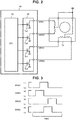
- FIG. 1 is a diagram schematically illustrating a configuration of a vehicle 20 according to one embodiment of the present invention.
- FIG. 2 is a diagram schematically illustrating configurations of a flow path switching valve driving motor 72 and a motor driver 88.
- the vehicle 20 of the embodiment includes a motor 32, an inverter 34, an electronic control unit for a motor (hereinafter referred to as a "motor ECU") 35, a battery 36, an electronic control unit for a battery (hereinafter referred to as a “battery ECU”) 37, a system main relay 38, a battery boost converter 40, an FC boost converter 48, a fuel cell 50, a cooling device 60, a main electronic control unit (hereinafter referred to as a "main ECU”) 80, and an electronic control unit for authentication (hereinafter referred to as an "authentication ECU”) 100.
- a motor ECU an electronic control unit for a motor
- battery ECU an electronic control unit for a battery
- FC boost converter 48 for FC boost
- the motor 32 is composed of a synchronous motor drive, and includes a rotor in which a permanent magnet is embedded, and a stator on which a three-phase coil is wound.
- the rotor of the motor 32 is connected to a drive shaft 26, which is connected to drive wheels 22a, 22b via a differential gear 24.
- the inverter 34 is connected to the motor 32 and to high-voltage power lines 42.
- the inverter 34 is composed of a commonly known inverter circuit having six transistors and six diodes.
- the motor 32 is rotationally driven by the transistor of the inverter 34 that is switched and controlled by the motor ECU 35.
- the motor ECU 35 is composed of a microprocessor having a CPU as a main unit (not shown).
- the motor ECU 35 includes a ROM that stores a processing program, a RAM that temporarily stores data, an input and output port (not shown), a communication port (not shown), and the like.
- a rotational position ⁇ m , and the like, detected by a rotational position detection sensor (for example, a resolver) 32a that detects the rotational position of the rotor of the motor 32 is input into the motor ECU 35 through the input port. Further, a switching control signal, and the like, is output to the transistor of the inverter 34 through the output port from the motor ECU 35.
- the motor ECU 35 calculates the rotational frequency N m of the motor 32 based on the rotational position ⁇ m of the rotor of the motor 32, detected by the rotational position detection sensor 32a.
- the battery 36 is composed of, for example, a lithium-ion secondary battery or a nickel hydrogen secondary battery, and is connected to low-voltage power lines 44.
- the battery 36 is managed by a battery ECU 37.
- the battery ECU 37 is composed of a microprocessor having a CPU as a main unit (not shown). In addition to the CPU, the battery ECU 37 includes a ROM that stores a processing program, a RAM that temporarily stores data, an input and output port (not shown), a communication port (not shown), and the like.
- a voltage VB from a voltage sensor 36a mounted between terminals of the battery 36, a current IB from a current sensor 36b mounted on an output terminal of the battery 36, a battery temperature TB from a temperature sensor 36c mounted on the battery 36, and the like, are input into the battery ECU 37 through the input port.
- the battery ECU 37 calculates a storage ratio SOC based on the integrated value of the current IB from the current sensor 36b.
- the storage ratio SOC is a ratio of the capacity of power dischargeable from the battery 36 to the total capacity of the battery 36.
- the battery ECU 37 also calculates battery input and output limits Win and W out , which are the maximum allowable powers that may be charged to and discharged from the battery 36 based on the storage ratio SOC or the battery temperature TB from the temperature sensor 36c.
- the battery ECU 37 also sets a charge and discharge demand power P b * (the discharge side is positive) required by the battery 36.
- the battery boost converter 40 is connected to the high-voltage power lines 42 and the low-voltage power lines 44, and is composed of a commonly known buck-boost converter circuit having two transistors, two diodes, and one reactor.
- a smoothing capacitor 46 is connected to a positive electrode bus and a negative electrode bus of the high-voltage power line 42. Further, on the low-voltage power lines 44, the smoothing capacitor 46 is connected and the system main relay 38 is mounted.
- the fuel cell 50 is composed of a stack of solid polymer fuel cells, which is formed by laminating a plurality of cells, each of which consists of an electrolyte membrane, an anode electrode and a cathode electrode sandwiching the electrolyte membrane therebetween, and a separator serving as a wall between the cells.
- the fuel cell 50 generates electric power from an electrochemical reaction between hydrogen supplied from a hydrogen tank 52 to the anode electrode through a hydrogen valve 54 and oxygen in the air supplied from a blower 56 to the cathode electrode.
- the fuel cell 50 is cooled by the cooling device 60 exchanging heat with a coolant (cooling water).
- the cooling device 60 includes a circulation flow path 62 that connects the radiator 64 and the fuel cell 50, a circulation pump 66 that circulates the coolant in the circulation flow path 62, a bypass flow path 68 that connects the upstream side and the downstream side of the radiator 64 in the circulation flow path 62, and a flow path switching valve 70 that switches the destination of the coolant that passes through the fuel cell 50 to circulate to the radiator 64 side and the bypass flow path 68 side.
- the flow path switching valve 70 is composed of a rotary valve in the present embodiment.
- the rotational position of the flow path switching valve 70 is adjusted by the flow path switching valve driving motor 72. As such, it is possible to adjust a distribution ratio of a flow rate of the coolant supplied on the radiator 64 to a flow rate of the coolant supplied on the bypass flow path 68.
- the flow path switching valve driving motor 72 is composed of a two-phase stepping motor, and is driven by the motor driver 88 provided in the main ECU 80.
- the motor driver 88 is composed of a unipolar driving motor driver having four transistors Ta1, Ta2, Tb1, Tb2.
- the motor driver 88 drives and controls the flow path switching valve driving motor 72, using a two-phase excitation which excites the coil by two phases per excitation.
- the motor driver 88 is not limited to the unipolar driving driver and may be a bipolar driving driver having eight transistors.
- the excitation method is not limited to the two-phase excitation, and may be a one-phase excitation, a one-two-phase excitation, and the like.
- the FC boost converter 48 is connected to an output terminal of the fuel cell 50 and the high-voltage power lines 42, and is composed of a commonly known boost converter circuit having one transistor, one diode, and one reactor.
- the main ECU 80 is composed of a microprocessor having a CPU as a main unit (not shown).
- the main ECU 80 includes a ROM that stores a processing program, a RAM that temporarily stores data, an input and output port (not shown), a communication port (not shown), and the like.
- Signals from various sensors are input into the main ECU 80 through the input port.
- Examples of a signal input into the main ECU 80 include an inlet temperature T in (the temperature of the coolant near the inlet) from a temperature sensor 62a mounted near the inlet where the coolant flows into the fuel cell 50, or an outlet temperature T out (the temperature of the coolant near the outlet) from a temperature sensor 62b mounted near the outlet where the coolant flows out from the fuel cell 50.
- T in the temperature of the coolant near the inlet
- T out the temperature of the coolant near the outlet
- Examples of such information include an ignition signal IG from an ignition switch 90, a shift position SP from a shift position sensor 92 that detects the an operation position of a shift lever 91, an accelerator opening degree A cc from an accelerator pedal position sensor 94 that detects a depression amount of an accelerator pedal 93, a brake pedal position BP from the brake pedal position sensor 96 that detects a depression amount of the brake pedal 95, and a vehicle speed V from the vehicle speed sensor 98.
- Various control signals are output from the main ECU 80 through the output port.
- Examples of a signal output from the main ECU 80 include a drive control signal to the system main relay 38, the switching control signal to a transistor of the battery boost converter 40, and the switching control signal to a transistor of the FC boost converter 48.
- examples of the signal include a drive signal to a pump motor that drives the circulation pump 66, a drive signal to a hydrogen valve driving motor that drives the hydrogen valve 54, and a drive signal to the flow path switching valve driving motor 72.
- the main ECU 80 is communicably connected to the motor ECU 35, the battery ECU 37 and the authentication ECU 100, and exchanges various kinds of information and various signals with the motor ECU 35, the battery ECU 37, and the authentication ECU 100.
- the main ECU 80 In a case of receiving a signal permitting start of the vehicle 20, output from the authentication ECU 100, the main ECU 80 turns on the system main relay 38 and activates the fuel cell 50 to set the vehicle 20 to a travelable state (a ready-on state) when the ignition switch 90 is turned on. On the other hand, in a case of receiving a signal inhibiting activation of the system, output from the authentication ECU 100, the main ECU 80 does not turn on the system main relay 38 even if the ignition switch 90 is turned on.
- the main ECU 80 controls the operation of the fuel cell 50, and drives and controls the motor 32 such that a demand torque T d * according to the accelerator opening degree A cc is output to the drive shaft 26, using the power generated from the fuel cell 50 or the charge and discharge power from the battery 36. Further, when the fuel cell 50 is activated, the main ECU 80 controls the cooling device 60 such that the temperature of the fuel cell 50 is maintained at an appropriate temperature.
- the control of the cooling device 60 is performed by setting a target valve position (the distribution ratio of the flow rate of the coolant to the radiator 64 to the flow rate of the coolant to the bypass flow path 68) of the flow path switching valve 70 such that the outlet temperature T out becomes a target temperature (for example, 60°C to 70°C) based on the inlet temperature T in from the temperature sensor 62a and the outlet temperature T out from the temperature sensor 62b, and by driving and controlling the flow path switching valve driving motor 72 such that the valve position of the flow path switching valve 70 is set to the target valve position.
- a target valve position the distribution ratio of the flow rate of the coolant to the radiator 64 to the flow rate of the coolant to the bypass flow path 68
- the flow path switching valve driving motor 72 is composed of the stepping motor, driving and controlling the flow path switching valve driving motor 72 is performed by outputting a pulse signal from the motor driver 88 such that the number of steps from the original position matches the number of steps corresponding to the target valve position.
- the authentication ECU 100 is composed of a microprocessor having a CPU as a main unit (not shown). In addition to the CPU, the authentication ECU 100 includes a ROM that stores a processing program, a RAM that temporarily stores data, an input and output port (not shown), a communication port (not shown), and the like.
- the authentication ECU 100 is connected to a transmitter that transmits a request signal to a detection area on the outside of the vehicle 20 and inside the passenger compartment, and a receiver that receives an ID code transmitted from a smart key 102 in response to reception of the request signal.
- the authentication ECU 100 checks the ID code received from the smart key 102 and automatically unlocks the door. Conversely, when the driver carrying the smart key 102 unlocks the door, exits the vehicle 20 and goes away from the detection area, the authentication ECU 100 automatically locks the door.
- the authentication ECU 100 when the received ID code proves to be correct as a result of checking, the authentication ECU 100 outputs a signal permitting the start of the vehicle 20 to the main ECU 80. Conversely, when the received ID code cannot be checked or proves to be incorrect as a result of checking, the authentication ECU 100 outputs a signal inhibiting the start of the vehicle 20 to the main ECU 80. Further, an opening or closing signal that detects opening or closing of the door is also input from a door switch into the authentication ECU 100 through the input port. When the opening of the door is detected by the door switch during the start (during the ready-on state) of the vehicle 20, the authentication ECU 100 transmits the request signal to the detection area, receives the ID code from the smart key 102, and checks the received ID code. Conversely, when the received ID code cannot be checked or proves to be incorrect as a result of checking, the authentication ECU 100 turns on a warning light and repeats checking the ID code at predetermined time intervals.
- FIG. 4 is a flowchart illustrating an example of an authentication processing routine performed by the authentication ECU 100.
- the routine is repeatedly performed every predetermined time (for example, every several milliseconds) during the start of the vehicle 20 (during the ready-on state).
- step S100 the CPU of the authentication ECU 100 first determines whether to start the authentication of the smart key 102 (step S100). When the CPU determines not to start the authentication, the authentication process is terminated. On the other hand, when the CPU determines to start the authentication, the position (opening degree) of the flow path switching valve 70 is fixed (step S110). The process of step S110 is performed by outputting, to the main ECU 80, a control command for fixing the valve position. As illustrated in FIG. 5 , upon reception of the control command, the main ECU 80 controls the motor driver 88 such that the motor driver 88 maintains the state in which the two-phase coil is electrically excited, and locks an output shaft of the flow path switching valve driving motor 72 at the rotational position in the state.
- step S110 may be performed by stopping application of electricity to all the coils.
- an FC output limit W fclim which is the upper limit value of the output that the fuel cell 50 can generate, is set (step S120), and simultaneously the FC output limit flag F fclim for limiting the output of the fuel cell 50 is set to the value 1 (step S130).
- the current valve position can be detected by counting the number of steps from the original position.
- the output of the fuel cell 50 is limited when the valve position of the flow path switching valve 70 is fixed because, in some cases, the fuel cell 50 cannot be sufficiently cooled by the cooling device 60 when the valve position is fixed.
- the valve position of the flow path switching valve 70 when the valve position of the flow path switching valve 70 is fixed at a position where it is fully open to the bypass flow path 68 side, the fuel cell 50 is not substantially cooled. As a result, the fuel cell 50 may overheat due to lack of cooling when the fuel cell 50 is operated as usual. Therefore, in the present embodiment, even though the valve position is fixed to curb the occurrence of surge noise when the authentication of the smart key 102 is performed, the output of the fuel cell 50 is simultaneously limited to curb overheating of the fuel cell 50 due to lack of cooling.
- the FC output limit W fclim is set by determining the relationship between the current valve position and the FC output limit W fclim in advance and storing the relationship in the ROM as a map for setting the FC output limit, and, when the current valve position is given, deriving, from the map, the FC output limit W fclim corresponding to the current valve position.
- An example of the map for setting the FC output limit is illustrated in FIG. 6 .
- the FC output limit W fclim is set to increase (that is, the output limit of the fuel cell 50 is alleviated) as the current valve position is closer to the position where the valve is fully open to the radiator 64 side.
- step S140 it is respectively determined whether the authentication is completed (step S140), and whether a predetermined time has elapsed after the start of the authentication (step S150).
- the predetermined time is slightly longer than the time generally required for authentication, and is set to, for example, 3 seconds.
- the process returns to step S140 and is repeated.
- step S160 the fixing of the valve position of the flow path switching valve 70 is released (step S160) and simultaneously the FC output limit flag F fclim is set to the value 0 such that the output limit of the fuel cell 50 is canceled (step S170). Then, the authentication processing routine is terminated.
- the authentication processing routine is performed during the start of the vehicle 20 as described above.
- the authentication of the smart key 102 (checking the ID code) during the start of the vehicle 20 is performed when, for example, the ID code proves to be correct as a result of checking the ID code at the activation of the smart key system, and the vehicle 20 is started, but then the door is opened and the smart key 102 is brought out.
- the starting state (the ready-on state) of the vehicle 20 is maintained until the ignition is turned off, it is possible to curb an occurrence of an authentication failure and overheating of the fuel cell 50 due to lack of the coolant by fixing the valve position of the flow path switching valve 70 and limiting the output of the fuel cell 50.
- FIG. 8 is a flowchart illustrating an example of the operation controlling routine performed by the main ECU 80.
- the routine is repeatedly performed at every predetermined time (for example, every several milliseconds) during the start of the vehicle 20 (during the ready-on state).
- the CPU 82 of the main ECU 80 first inputs data required for controlling, such as the accelerator opening degree A cc from the accelerator pedal position sensor 94, the vehicle speed V from the vehicle speed sensor 98, the rotational frequency N m of the motor 32, the battery output limit W out , the FC output limit flag F fclim , the FC output limit W fclim , and the charge and discharge demand power P b * required by the battery 36 (step S200).
- the rotational frequency N m of the motor 32 is acquired from the motor ECU 35 via communication
- the battery output limit W out or the charge and discharge demand power P b * is acquired from the battery ECU 37 via communication.
- FC output limit flag F fclim or the FC output limit W fclim is acquired from the authentication ECU 100 via communication. Subsequently, based on the input accelerator opening degree A cc and the vehicle speed V, the demand torque T d * required for traveling and a vehicle demand power P* required for the entire vehicle 20 are set (step S210).
- the demand torque T d * is acquired by determining the relationship between the accelerator opening degree A cc , the vehicle speed V, and the demand torque T d * in advance and storing the relationship in the ROM 84 as a map for setting the demand torque T d *, and deriving, from the map, a corresponding demand torque T d * when the accelerator opening degree A cc and the vehicle speed V are given.
- the vehicle demand power P* is calculated by subtracting the charge and discharge demand power P b * (the discharge side is positive) from a traveling demand power that is acquired by multiplying the demand torque T d * by the rotational frequency N m of the motor 32.
- FC output limit flag F fclim has a value 1, that is, whether the output of the fuel cell 50 is limited during the authentication of the smart key 102 (step S220).
- FC output limit flag F fclim is not the value 1 but the value 0
- the smaller one of the vehicle demand power P* and the rated maximum output W fcmax of the fuel cell 50 is set as an FC target output P fc * (step S240).
- the FC output limit flag F fclim is the value 1
- the smaller one of the vehicle demand power P* and the FC output limit W fclim is set as the FC target output P fc * (step S230).
- a torque limit T mlim which is the upper limit of the torque that can be output from the motor 32, is set by dividing the sum of the FC target output P fc * and the battery output limit W out by the rotational frequency N m of the motor 32 (step S250). Then, the smaller one of the demand torque T d * and the torque limit T mlim is set as a command torque T m * to be output from the motor 32 (step S260).
- the valve position of the flow path switching valve 70 of the cooling device 60 is fixed, and simultaneously the output of the fuel cell 50 is limited. Conversely, when the authentication is terminated or the predetermined time has elapsed, the fixing of the valve position is released and the output limit of the fuel cell 50 is canceled. As such, it is possible to curb the occurrence of noise that may interfere with communication with the smart key 102 by fixing the valve position of the flow path switching valve 70, and curb overheating of the fuel cell 50 even if the valve position of the flow path switching valve 70 is fixed near the position where it is fully open to the bypass flow path 68 side.
- the FC output limit W fclim is set such that the output limit of the fuel cell 50 is alleviated as the fixed valve position of the flow path switching valve 70 is closer to the position where it is fully open to the radiator 64 side.
- the output of the fuel cell 50 is not excessively limited, an adverse effect caused by limiting the output of the fuel cell 50, for example, a decrease in torque used for traveling a vehicle or a decrease in the storage ratio SOC of the battery 36, can be minimized.
- the flow path switching valve driving motor 72 is composed of a stepping motor.
- any type of motor may be employed as long as the motor can adjust the opening degree of the flow path switching valve 70.
- a rotational position detection sensor that detects the valve position of the flow path switching valve 70 may be separately provided.
- the value changed based on the valve position of the flow path switching valve 70 is set as the output limit W fclim .
- a constant value may be set as the output limit W fclim .
Landscapes
- Engineering & Computer Science (AREA)
- Life Sciences & Earth Sciences (AREA)
- Sustainable Development (AREA)
- Sustainable Energy (AREA)
- Mechanical Engineering (AREA)
- Chemical & Material Sciences (AREA)
- Transportation (AREA)
- Manufacturing & Machinery (AREA)
- General Chemical & Material Sciences (AREA)
- Electrochemistry (AREA)
- Chemical Kinetics & Catalysis (AREA)
- Power Engineering (AREA)
- Combustion & Propulsion (AREA)
- Signal Processing (AREA)
- Computer Networks & Wireless Communication (AREA)
- Physics & Mathematics (AREA)
- Thermal Sciences (AREA)
- Fuel Cell (AREA)
- Electric Propulsion And Braking For Vehicles (AREA)
- Lock And Its Accessories (AREA)
Abstract
Description
- The present invention relates to a vehicle provided with a fuel cell, a cooling device, a smart key system, and a control device and a control method.
- As a vehicle of the above type, a vehicle provided with a keyless entry system that authenticates a mobile device via communication and unlocks the locked state of an opening and closing body (a door) of the vehicle has been proposed (for example, see Japanese Unexamined Patent Application Publication No.
2010-133181 - There exists a fuel cell vehicle on which a fuel cell, which supplies electric power to a traveling motor, is mounted as one form of a vehicle. Generally, the fuel cell vehicle is provided with a cooling device that cools the fuel cell by exchanging heat with a coolant to maintain the fuel cell at an appropriate operating temperature. The cooling device may be provided with a circulation flow path that connects the fuel cell and a radiator, a pump that circulates the coolant in the circulation flow path, a bypass flow path that connects the upstream side and the downstream side of the radiator in the circulation flow path, a flow path switching valve that switches the destination of the coolant that passes through the fuel cell to circulate to the radiator side and the bypass flow path side, and a valve driving motor that drives the flow path switching valve. In the fuel cell vehicle, when the keyless entry system described above is provided, it can be considered that the operation of the valve driving motor is suppress at the time of authentication to prevent interference by noise generated by the operation of the valve driving motor during communication with a mobile device. However, depending on the valve position of the flow path switching valve at that time, the fuel cell may not be sufficiently cooled.
- The present invention provides a vehicle and a control method that can curb the generation of noise, which occurs with an operation of a flow path switching valve and interferes with authentication of a mobile device, and sufficiently cool a fuel cell.
- A vehicle according to a first aspect of the present invention includes a fuel cell, a cooling device configured to cool the fuel cell by exchanging heat with a coolant, a smart key system configured to communicate with a mobile device and perform authentication of the mobile device, and a control device configured to control the fuel cell and the cooling device. The cooling device includes a circulation flow path configured to connect the fuel cell and a radiator, a pump configured to circulate the coolant in the circulation flow path, a bypass flow path configured to connect the upstream side and the downstream side of the radiator in the circulation flow path, a flow path switching valve configured to switch the destination of the coolant that passes through the fuel cell to circulate to the radiator side and the bypass flow path side, and a motor configured to drive the flow path switching valve. When the smart key system performs the authentication of the mobile device, the control device is configured to stop an operation of the flow path switching valve simultaneously with limiting output of the fuel cell.
- According to the above first aspect, when the authentication of the mobile device is completed or when a predetermined time elapses after the operation of the flow path switching valve is stopped, the control device may release the stopped state of the operation of the flow path switching valve simultaneously with canceling the limit of the output of the fuel cell.
- When the smart key system performs the authentication of the mobile device by, the control device stops the operation of the flow path switching valve and limits the output of the fuel cell. When the authentication of the mobile device is completed or when the predetermined time elapses, the control device releases the stopped state of the operation of the flow path switching valve simultaneously with canceling the limit of the output of the fuel cell. As such, it is possible to curb the occurrence of noise, from the motor, which may interfere with communication with the mobile device, simultaneously with curbing overheating of the fuel cell even though the valve position of the flow path switching valve is fixed near the position where it is fully open to the bypass flow path side. Here, "motor" includes a stepping motor.
- According to the above first aspect, the flow path switching valve may adjust a distribution ratio of a flow rate of the coolant flowing on the radiator to a flow rate of the coolant flowing on the bypass flow path. The control device may stop, when the smart key system performs the authentication, the operation of the flow path switching valve, and set the maximum output of the fuel cell based on the position at which the flow path switching valve is stopped, and control the fuel cell such that the output of the fuel cell does not exceed the maximum output.
- According to the above first aspect, the control device may set the maximum output such that a larger output from the fuel cell is allowed when the position at which the flow path switching valve is stopped is on the radiator side than when the position at which the flow path switching valve is stopped is on the bypass flow path side.
- As such, since the output of the fuel cell is not excessively limited, an adverse effect caused by limiting the output of the fuel cell can be minimized.
- According to the above first aspect, the motor may be a stepping motor. When the smart key system performs the authentication, the control device may fix the valve position of the flow path switching valve by maintaining electrical excitation to a coil of the motor.
- As such, it is possible to more accurately determine the valve position of the flow path switching valve, simultaneously with appropriately fixing the position of the valve when the authentication is performed.
- According to the above first aspect, the flow path switching valve may adjust the distribution ratio of the flow rate of the coolant flowing on the radiator to the flow rate of the coolant flowing on the bypass flow path. The control device may set a maximum output of the fuel cell based on the distribution ratio, and when the smart key system performs the authentication, control the fuel cell such that the output of the fuel cell does not exceed the maximum output.
- According to the above first aspect, the control device may set the maximum output such that the larger the flow rate of the coolant flowing on the radiator is in the distribution ratio, the larger the maximum output becomes.
- A control method according to a second aspect of the present invention controls a cooling device of a fuel cell mounted on a vehicle. The control method includes a step of stopping an operation of a flow path switching valve and limiting output of the fuel cell when a smart key system mounted on the vehicle performs authentication of a mobile device. The fuel cell is connected to a radiator via a circulation flow path in which a coolant circulates. The upstream side and the downstream side of the radiator in the circulation flow path are connected to each other via a bypass flow path. The flow path switching valve switches the destination of the coolant that passes through the fuel cell to circulate to the radiator side and the bypass flow path side.
- According to the above second aspect, the control method may further include a step of canceling the limit of the output of the fuel cell by resuming the operation of the flow path switching valve when the authentication of the mobile device is completed or when a predetermined time elapses after the operation of the flow path switching valve is stopped.
- According to the above second aspect, the control method may further include a step of setting a maximum output of the fuel cell based on the distribution ratio of the flow rate of the coolant flowing on the radiator to the flow rate of the coolant flowing on the bypass flow path, and a step of controlling the fuel cell such that the output of the fuel cell does not exceed the maximum output when the authentication is performed.
- Features, advantages, and technical and industrial significance of exemplary embodiments of the invention will be described below with reference to the accompanying drawings, in which like signs denote like elements, and wherein:
-
FIG. 1 is a diagram schematically illustrating a configuration of a vehicle according to one embodiment of the present invention; -
FIG. 2 is a diagram schematically illustrating configurations of a flow path switching valve driving motor and a motor driver; -
FIG. 3 is a diagram illustrating an example of waveforms shaped by application of electricity at the time at which the flow path switching valve driving motor is driven; -
FIG. 4 is a flowchart illustrating an example of an authentication processing routine performed by an authentication ECU; -
FIG. 5 is a diagram illustrating an example of waveforms shaped by application of electricity at the time at which the flow path switching valve driving motor is locked; -
FIG. 6 is a diagram illustrating an example of a map for setting a limit of fuel cell (FC) output; -
FIG. 7 is a diagram illustrating a relationship between the FC output and an amount of power generated from the FC; and -
FIG. 8 is a flowchart illustrating an example of an operation controlling routine performed by a main ECU. - Next, an embodiment of the present invention will be described with reference to the drawings.
-
FIG. 1 is a diagram schematically illustrating a configuration of avehicle 20 according to one embodiment of the present invention.FIG. 2 is a diagram schematically illustrating configurations of a flow path switchingvalve driving motor 72 and amotor driver 88. As illustrated, thevehicle 20 of the embodiment includes amotor 32, aninverter 34, an electronic control unit for a motor (hereinafter referred to as a "motor ECU") 35, abattery 36, an electronic control unit for a battery (hereinafter referred to as a "battery ECU") 37, a systemmain relay 38, abattery boost converter 40, an FCboost converter 48, afuel cell 50, a cooling device 60, a main electronic control unit (hereinafter referred to as a "main ECU") 80, and an electronic control unit for authentication (hereinafter referred to as an "authentication ECU") 100. - The
motor 32 is composed of a synchronous motor drive, and includes a rotor in which a permanent magnet is embedded, and a stator on which a three-phase coil is wound. The rotor of themotor 32 is connected to adrive shaft 26, which is connected todrive wheels differential gear 24. Theinverter 34 is connected to themotor 32 and to high-voltage power lines 42. Theinverter 34 is composed of a commonly known inverter circuit having six transistors and six diodes. Themotor 32 is rotationally driven by the transistor of theinverter 34 that is switched and controlled by the motor ECU 35. - The motor ECU 35 is composed of a microprocessor having a CPU as a main unit (not shown). In addition to the CPU, the
motor ECU 35 includes a ROM that stores a processing program, a RAM that temporarily stores data, an input and output port (not shown), a communication port (not shown), and the like. A rotational position θm, and the like, detected by a rotational position detection sensor (for example, a resolver) 32a that detects the rotational position of the rotor of themotor 32 is input into themotor ECU 35 through the input port. Further, a switching control signal, and the like, is output to the transistor of theinverter 34 through the output port from themotor ECU 35. Themotor ECU 35 calculates the rotational frequency Nm of themotor 32 based on the rotational position θm of the rotor of themotor 32, detected by the rotationalposition detection sensor 32a. - The
battery 36 is composed of, for example, a lithium-ion secondary battery or a nickel hydrogen secondary battery, and is connected to low-voltage power lines 44. Thebattery 36 is managed by abattery ECU 37. - The
battery ECU 37 is composed of a microprocessor having a CPU as a main unit (not shown). In addition to the CPU, thebattery ECU 37 includes a ROM that stores a processing program, a RAM that temporarily stores data, an input and output port (not shown), a communication port (not shown), and the like. A voltage VB from avoltage sensor 36a mounted between terminals of thebattery 36, a current IB from acurrent sensor 36b mounted on an output terminal of thebattery 36, a battery temperature TB from atemperature sensor 36c mounted on thebattery 36, and the like, are input into thebattery ECU 37 through the input port. Thebattery ECU 37 calculates a storage ratio SOC based on the integrated value of the current IB from thecurrent sensor 36b. The storage ratio SOC is a ratio of the capacity of power dischargeable from thebattery 36 to the total capacity of thebattery 36. Moreover, thebattery ECU 37 also calculates battery input and output limits Win and Wout, which are the maximum allowable powers that may be charged to and discharged from thebattery 36 based on the storage ratio SOC or the battery temperature TB from thetemperature sensor 36c. Furthermore, based on the storage ratio SOC, thebattery ECU 37 also sets a charge and discharge demand power Pb* (the discharge side is positive) required by thebattery 36. - The
battery boost converter 40 is connected to the high-voltage power lines 42 and the low-voltage power lines 44, and is composed of a commonly known buck-boost converter circuit having two transistors, two diodes, and one reactor. - A smoothing
capacitor 46 is connected to a positive electrode bus and a negative electrode bus of the high-voltage power line 42. Further, on the low-voltage power lines 44, the smoothingcapacitor 46 is connected and the systemmain relay 38 is mounted. - The
fuel cell 50 is composed of a stack of solid polymer fuel cells, which is formed by laminating a plurality of cells, each of which consists of an electrolyte membrane, an anode electrode and a cathode electrode sandwiching the electrolyte membrane therebetween, and a separator serving as a wall between the cells. Thefuel cell 50 generates electric power from an electrochemical reaction between hydrogen supplied from ahydrogen tank 52 to the anode electrode through ahydrogen valve 54 and oxygen in the air supplied from ablower 56 to the cathode electrode. - The
fuel cell 50 is cooled by the cooling device 60 exchanging heat with a coolant (cooling water). The cooling device 60 includes acirculation flow path 62 that connects theradiator 64 and thefuel cell 50, acirculation pump 66 that circulates the coolant in thecirculation flow path 62, abypass flow path 68 that connects the upstream side and the downstream side of theradiator 64 in thecirculation flow path 62, and a flowpath switching valve 70 that switches the destination of the coolant that passes through thefuel cell 50 to circulate to theradiator 64 side and thebypass flow path 68 side. - The flow
path switching valve 70 is composed of a rotary valve in the present embodiment. The rotational position of the flowpath switching valve 70 is adjusted by the flow path switchingvalve driving motor 72. As such, it is possible to adjust a distribution ratio of a flow rate of the coolant supplied on theradiator 64 to a flow rate of the coolant supplied on thebypass flow path 68. - In the present embodiment, as illustrated in
FIG. 2 , the flow path switchingvalve driving motor 72 is composed of a two-phase stepping motor, and is driven by themotor driver 88 provided in themain ECU 80. In the present embodiment, themotor driver 88 is composed of a unipolar driving motor driver having four transistors Ta1, Ta2, Tb1, Tb2. In the present embodiment, as illustrated inFIG. 3 , themotor driver 88 drives and controls the flow path switchingvalve driving motor 72, using a two-phase excitation which excites the coil by two phases per excitation. In addition, themotor driver 88 is not limited to the unipolar driving driver and may be a bipolar driving driver having eight transistors. Moreover, the excitation method is not limited to the two-phase excitation, and may be a one-phase excitation, a one-two-phase excitation, and the like. - The
FC boost converter 48 is connected to an output terminal of thefuel cell 50 and the high-voltage power lines 42, and is composed of a commonly known boost converter circuit having one transistor, one diode, and one reactor. - The
main ECU 80 is composed of a microprocessor having a CPU as a main unit (not shown). In addition to the CPU, themain ECU 80 includes a ROM that stores a processing program, a RAM that temporarily stores data, an input and output port (not shown), a communication port (not shown), and the like. - Signals from various sensors are input into the
main ECU 80 through the input port. Examples of a signal input into themain ECU 80 include an inlet temperature Tin (the temperature of the coolant near the inlet) from atemperature sensor 62a mounted near the inlet where the coolant flows into thefuel cell 50, or an outlet temperature Tout (the temperature of the coolant near the outlet) from atemperature sensor 62b mounted near the outlet where the coolant flows out from thefuel cell 50. Further, since themain ECU 80 also functions as a drive control device for thevehicle 20, information required for travel control is also input. Examples of such information include an ignition signal IG from anignition switch 90, a shift position SP from ashift position sensor 92 that detects the an operation position of ashift lever 91, an accelerator opening degree Acc from an acceleratorpedal position sensor 94 that detects a depression amount of anaccelerator pedal 93, a brake pedal position BP from the brakepedal position sensor 96 that detects a depression amount of thebrake pedal 95, and a vehicle speed V from thevehicle speed sensor 98. - Various control signals are output from the
main ECU 80 through the output port. Examples of a signal output from themain ECU 80 include a drive control signal to the systemmain relay 38, the switching control signal to a transistor of thebattery boost converter 40, and the switching control signal to a transistor of theFC boost converter 48. In addition, examples of the signal include a drive signal to a pump motor that drives thecirculation pump 66, a drive signal to a hydrogen valve driving motor that drives thehydrogen valve 54, and a drive signal to the flow path switchingvalve driving motor 72. - The
main ECU 80 is communicably connected to themotor ECU 35, thebattery ECU 37 and theauthentication ECU 100, and exchanges various kinds of information and various signals with themotor ECU 35, thebattery ECU 37, and theauthentication ECU 100. - In a case of receiving a signal permitting start of the
vehicle 20, output from theauthentication ECU 100, themain ECU 80 turns on the systemmain relay 38 and activates thefuel cell 50 to set thevehicle 20 to a travelable state (a ready-on state) when theignition switch 90 is turned on. On the other hand, in a case of receiving a signal inhibiting activation of the system, output from theauthentication ECU 100, themain ECU 80 does not turn on the systemmain relay 38 even if theignition switch 90 is turned on. - When the
vehicle 20 is set to the ready-on state by the activation of thefuel cell 50, themain ECU 80 controls the operation of thefuel cell 50, and drives and controls themotor 32 such that a demand torque Td* according to the accelerator opening degree Acc is output to thedrive shaft 26, using the power generated from thefuel cell 50 or the charge and discharge power from thebattery 36. Further, when thefuel cell 50 is activated, themain ECU 80 controls the cooling device 60 such that the temperature of thefuel cell 50 is maintained at an appropriate temperature. The control of the cooling device 60 is performed by setting a target valve position (the distribution ratio of the flow rate of the coolant to theradiator 64 to the flow rate of the coolant to the bypass flow path 68) of the flowpath switching valve 70 such that the outlet temperature Tout becomes a target temperature (for example, 60°C to 70°C) based on the inlet temperature Tin from thetemperature sensor 62a and the outlet temperature Tout from thetemperature sensor 62b, and by driving and controlling the flow path switchingvalve driving motor 72 such that the valve position of the flowpath switching valve 70 is set to the target valve position. In the present embodiment, since the flow path switchingvalve driving motor 72 is composed of the stepping motor, driving and controlling the flow path switchingvalve driving motor 72 is performed by outputting a pulse signal from themotor driver 88 such that the number of steps from the original position matches the number of steps corresponding to the target valve position. - The
authentication ECU 100 is composed of a microprocessor having a CPU as a main unit (not shown). In addition to the CPU, theauthentication ECU 100 includes a ROM that stores a processing program, a RAM that temporarily stores data, an input and output port (not shown), a communication port (not shown), and the like. - Although illustration is omitted, the
authentication ECU 100 is connected to a transmitter that transmits a request signal to a detection area on the outside of thevehicle 20 and inside the passenger compartment, and a receiver that receives an ID code transmitted from asmart key 102 in response to reception of the request signal. When a driver carrying thesmart key 102 enters the detection area, theauthentication ECU 100 checks the ID code received from thesmart key 102 and automatically unlocks the door. Conversely, when the driver carrying thesmart key 102 unlocks the door, exits thevehicle 20 and goes away from the detection area, theauthentication ECU 100 automatically locks the door. - In addition, when the received ID code proves to be correct as a result of checking, the
authentication ECU 100 outputs a signal permitting the start of thevehicle 20 to themain ECU 80. Conversely, when the received ID code cannot be checked or proves to be incorrect as a result of checking, theauthentication ECU 100 outputs a signal inhibiting the start of thevehicle 20 to themain ECU 80. Further, an opening or closing signal that detects opening or closing of the door is also input from a door switch into theauthentication ECU 100 through the input port. When the opening of the door is detected by the door switch during the start (during the ready-on state) of thevehicle 20, theauthentication ECU 100 transmits the request signal to the detection area, receives the ID code from thesmart key 102, and checks the received ID code. Conversely, when the received ID code cannot be checked or proves to be incorrect as a result of checking, theauthentication ECU 100 turns on a warning light and repeats checking the ID code at predetermined time intervals. - Next, an operation of the
vehicle 20 of the embodiment configured as the above will be described. Specifically, the operation of thevehicle 20 during authentication of thesmart key 102 will be described.FIG. 4 is a flowchart illustrating an example of an authentication processing routine performed by theauthentication ECU 100. The routine is repeatedly performed every predetermined time (for example, every several milliseconds) during the start of the vehicle 20 (during the ready-on state). - When an authentication process is performed, the CPU of the
authentication ECU 100 first determines whether to start the authentication of the smart key 102 (step S100). When the CPU determines not to start the authentication, the authentication process is terminated. On the other hand, when the CPU determines to start the authentication, the position (opening degree) of the flowpath switching valve 70 is fixed (step S110). The process of step S110 is performed by outputting, to themain ECU 80, a control command for fixing the valve position. As illustrated inFIG. 5 , upon reception of the control command, themain ECU 80 controls themotor driver 88 such that themotor driver 88 maintains the state in which the two-phase coil is electrically excited, and locks an output shaft of the flow path switchingvalve driving motor 72 at the rotational position in the state. It is possible to curb the occurrence of surge noise that interferes with communication between theauthentication ECU 100 and thesmart key 102 by fixing the on or off state of the transistors Ta1, Ta2, Tb1, Tb2 of themotor driver 88, and curb the occurrence of authentication failure. In addition, the process of step S110 may be performed by stopping application of electricity to all the coils. - Subsequently, based on the current valve position of the flow
path switching valve 70, an FC output limit Wfclim, which is the upper limit value of the output that thefuel cell 50 can generate, is set (step S120), and simultaneously the FC output limit flag Ffclim for limiting the output of thefuel cell 50 is set to the value 1 (step S130). Moreover, the current valve position can be detected by counting the number of steps from the original position. The output of thefuel cell 50 is limited when the valve position of the flowpath switching valve 70 is fixed because, in some cases, thefuel cell 50 cannot be sufficiently cooled by the cooling device 60 when the valve position is fixed. For example, when the valve position of the flowpath switching valve 70 is fixed at a position where it is fully open to thebypass flow path 68 side, thefuel cell 50 is not substantially cooled. As a result, thefuel cell 50 may overheat due to lack of cooling when thefuel cell 50 is operated as usual. Therefore, in the present embodiment, even though the valve position is fixed to curb the occurrence of surge noise when the authentication of thesmart key 102 is performed, the output of thefuel cell 50 is simultaneously limited to curb overheating of thefuel cell 50 due to lack of cooling. In the present embodiment, the FC output limit Wfclim is set by determining the relationship between the current valve position and the FC output limit Wfclim in advance and storing the relationship in the ROM as a map for setting the FC output limit, and, when the current valve position is given, deriving, from the map, the FC output limit Wfclim corresponding to the current valve position. An example of the map for setting the FC output limit is illustrated inFIG. 6 . As shown, the FC output limit Wfclim is set to increase (that is, the output limit of thefuel cell 50 is alleviated) as the current valve position is closer to the position where the valve is fully open to theradiator 64 side. It makes allowance for the fact that a heating value of thefuel cell 50 increases as the output increases, as illustrated inFIG. 7 . As such, it is possible to curb an excessive output limit of thefuel cell 50 while curbing overheating of thefuel cell 50. Further, when the valve is currently at the position where it is fully open to theradiator 64 side, the FC output limit Wfclim is set to a rated maximum output Wfcmax of thefuel cell 50, as illustrated inFIG. 6 . In such a case, the output of thefuel cell 50 is not substantially limited. - Then, it is respectively determined whether the authentication is completed (step S140), and whether a predetermined time has elapsed after the start of the authentication (step S150). Here, the predetermined time is slightly longer than the time generally required for authentication, and is set to, for example, 3 seconds. When it is determined that the authentication is not completed and the predetermined time has not elapsed, the process returns to step S140 and is repeated. On the other hand, when it is determined that the authentication is completed, or the predetermined time has elapsed without completion of the authentication, the fixing of the valve position of the flow
path switching valve 70 is released (step S160) and simultaneously the FC output limit flag Ffclim is set to the value 0 such that the output limit of thefuel cell 50 is canceled (step S170). Then, the authentication processing routine is terminated. - Here, the authentication processing routine is performed during the start of the
vehicle 20 as described above. The authentication of the smart key 102 (checking the ID code) during the start of thevehicle 20 is performed when, for example, the ID code proves to be correct as a result of checking the ID code at the activation of the smart key system, and thevehicle 20 is started, but then the door is opened and thesmart key 102 is brought out. In such a case, since the starting state (the ready-on state) of thevehicle 20 is maintained until the ignition is turned off, it is possible to curb an occurrence of an authentication failure and overheating of thefuel cell 50 due to lack of the coolant by fixing the valve position of the flowpath switching valve 70 and limiting the output of thefuel cell 50. - Next, control of the
vehicle 20 using the FC output limit flag Ffclim or the FC output limit Wfclim will be described.FIG. 8 is a flowchart illustrating an example of the operation controlling routine performed by themain ECU 80. The routine is repeatedly performed at every predetermined time (for example, every several milliseconds) during the start of the vehicle 20 (during the ready-on state). - When the operation controlling routine is performed, the
CPU 82 of themain ECU 80 first inputs data required for controlling, such as the accelerator opening degree Acc from the acceleratorpedal position sensor 94, the vehicle speed V from thevehicle speed sensor 98, the rotational frequency Nm of themotor 32, the battery output limit Wout, the FC output limit flag Ffclim, the FC output limit Wfclim, and the charge and discharge demand power Pb* required by the battery 36 (step S200). Moreover, the rotational frequency Nm of themotor 32 is acquired from themotor ECU 35 via communication, and the battery output limit Wout or the charge and discharge demand power Pb* is acquired from thebattery ECU 37 via communication. In addition, the FC output limit flag Ffclim or the FC output limit Wfclim is acquired from theauthentication ECU 100 via communication. Subsequently, based on the input accelerator opening degree Acc and the vehicle speed V, the demand torque Td* required for traveling and a vehicle demand power P* required for theentire vehicle 20 are set (step S210). Moreover, the demand torque Td* is acquired by determining the relationship between the accelerator opening degree Acc, the vehicle speed V, and the demand torque Td* in advance and storing the relationship in the ROM 84 as a map for setting the demand torque Td*, and deriving, from the map, a corresponding demand torque Td* when the accelerator opening degree Acc and the vehicle speed V are given. Further, the vehicle demand power P* is calculated by subtracting the charge and discharge demand power Pb* (the discharge side is positive) from a traveling demand power that is acquired by multiplying the demand torque Td* by the rotational frequency Nm of themotor 32. - Next, it is determined whether the FC output limit flag Ffclim has a
value 1, that is, whether the output of thefuel cell 50 is limited during the authentication of the smart key 102 (step S220). When it is determined that the FC output limit flag Ffclim is not thevalue 1 but the value 0, the smaller one of the vehicle demand power P* and the rated maximum output Wfcmax of thefuel cell 50 is set as an FC target output Pfc* (step S240). On the other hand, when it is determined that the FC output limit flag Ffclim is thevalue 1, the smaller one of the vehicle demand power P* and the FC output limit Wfclim is set as the FC target output Pfc* (step S230). Subsequently, a torque limit Tmlim, which is the upper limit of the torque that can be output from themotor 32, is set by dividing the sum of the FC target output Pfc* and the battery output limit Wout by the rotational frequency Nm of the motor 32 (step S250). Then, the smaller one of the demand torque Td* and the torque limit Tmlim is set as a command torque Tm* to be output from the motor 32 (step S260). In such a manner, when the FC target output Pfc* and the command torque Tm* are set, thehydrogen valve 54 and theblower 56 are controlled so that thefuel cell 50 can generate power with the FC target output Pfc*, and the transistor of theinverter 34 is switched and controlled so that a torque matching the command torque Tm* can be output from the motor 32 (step S270). Then the routine is terminated. - In the
vehicle 20 of the present embodiment described above, when the authentication of thesmart key 102 is performed, the valve position of the flowpath switching valve 70 of the cooling device 60 is fixed, and simultaneously the output of thefuel cell 50 is limited. Conversely, when the authentication is terminated or the predetermined time has elapsed, the fixing of the valve position is released and the output limit of thefuel cell 50 is canceled. As such, it is possible to curb the occurrence of noise that may interfere with communication with thesmart key 102 by fixing the valve position of the flowpath switching valve 70, and curb overheating of thefuel cell 50 even if the valve position of the flowpath switching valve 70 is fixed near the position where it is fully open to thebypass flow path 68 side. - Moreover, the FC output limit Wfclim is set such that the output limit of the
fuel cell 50 is alleviated as the fixed valve position of the flowpath switching valve 70 is closer to the position where it is fully open to theradiator 64 side. As such, since the output of thefuel cell 50 is not excessively limited, an adverse effect caused by limiting the output of thefuel cell 50, for example, a decrease in torque used for traveling a vehicle or a decrease in the storage ratio SOC of thebattery 36, can be minimized. - In the embodiment, it was described that the flow path switching
valve driving motor 72 is composed of a stepping motor. However, any type of motor may be employed as long as the motor can adjust the opening degree of the flowpath switching valve 70. In such a case, a rotational position detection sensor that detects the valve position of the flowpath switching valve 70 may be separately provided. - In the embodiment, the value changed based on the valve position of the flow
path switching valve 70 is set as the output limit Wfclim. However, regardless of the valve position of the flowpath switching valve 70, a constant value may be set as the output limit Wfclim.
Claims (10)
- A vehicle (20) comprising:a fuel cell (50);a cooling device (60) configured to cool the fuel cell (50) by exchanging heat with a coolant;a smart key system (100) configured to communicate with a mobile device (102) and performs authentication of the mobile device (102); anda control device (80) configured to control the fuel cell (50) and the cooling device (60),
wherein the cooling device (60) includes:a circulation flow path (62) configured to connect the fuel cell (50) and a radiator (64);a pump (66) configured to circulate the coolant in the circulation flow path (62);a bypass flow path (68) configured to connect an upstream side and a downstream side of the radiator(64) in the circulation flow path (62);a flow path switching valve (70) configured to switch a destination of the coolant that passes through the fuel cell (50) to circulate to a radiator (64) side and a bypass flow path (68) side; anda motor (72) configured to drive the flow path switching valve (70), and
wherein the control device (80) is configured to, when the smart key system (100) performs the authentication of the mobile device (102), stop an operation of the flow path switching valve (70) simultaneously with limiting output of the fuel cell (50). - The vehicle (20) according to claim 1, wherein the control device (80) is configured to, when the authentication of the mobile device (102) is completed or when a predetermined time elapses after the operation of the flow path switching valve (70) is stopped, release a stopped state of the operation of the flow path switching valve (70) simultaneously with canceling a limit of the output of the fuel cell (50).
- The vehicle (20) according to claim 1 or 2, wherein:the flow path switching valve (70) is configured to adjust a distribution ratio of a flow rate of the coolant flowing on the radiator (64) to a flow rate of the coolant flowing on the bypass flow path (68); andthe control device (80) is configured to:when the smart key system (100) performs the authentication, stop the operation of the flow path switching valve (70);set a maximum output of the fuel cell (50) based on a position at which the flow path switching valve (70) is stopped; andcontrol the fuel cell (50) such that the output of the fuel cell (50) does not exceed the maximum output.
- The vehicle (20) according to claim 3, wherein the control device (80) is configured to set the maximum output such that a larger output from the fuel cell (50) is allowed when the position at which the flow path switching valve (70) is stopped is on the radiator (64) side than when the position at which the flow path switching valve (70) is stopped is on the bypass flow path (68) side.
- The vehicle (20) according to claim 3 or 4, wherein:the motor (72) is a stepping motor; andthe control device (80) is configured to, when the smart key system (100) performs the authentication, fix a position of the flow path switching valve (70) by maintaining electrical excitation to a coil of the motor (72).
- The vehicle (20) according to claim 1 or 2, wherein:the flow path switching valve (70) is configured to adjust a distribution ratio of a flow rate of the coolant flowing on the radiator (64) to a flow rate of the coolant flowing on the bypass flow path (68); andthe control device (80) is configured to:set a maximum output of the fuel cell (50) based on the distribution ratio; andwhen the smart key system (100) performs the authentication, control the fuel cell (50) such that the output of the fuel cell (50) does not exceed the maximum output.
- The vehicle (20) according to claim 6, wherein the control device (80) is configured to set the maximum output such that the larger the flow rate of the coolant flowing on the radiator (64) is in the distribution ratio, the larger the maximum output becomes.
- A control method, the control method controlling a cooling device (60) of a fuel cell (50) mounted on a vehicle (20), the control method comprising:
stopping an operation of a flow path switching valve (70) and limiting output of the fuel cell (50) when a smart key system (100) mounted on the vehicle (20) performs authentication of a mobile device (102), wherein:the fuel cell (50) is connected to a radiator (64) via a circulation flow path (62) in which a coolant circulates;an upstream side and a downstream side of the radiator (64) in the circulation flow path (62) are connected to each other via a bypass flow path (68); andthe flow path switching valve (70) is configured to switch a destination of the coolant that passes through the fuel cell (50) to circulate to a radiator (64) side and a bypass flow path (68) side. - The control method according to claim 8 further comprising canceling a limit of the output of the fuel cell (50) by resuming the operation of the flow path switching valve (70) when the authentication of the mobile device (102) is completed or when a predetermined time elapses after the operation of the flow path switching valve (70) is stopped.
- The control method according to claim 8 or 9 further comprising:setting a maximum output of the fuel cell (50) based on a distribution ratio of a flow rate of the coolant flowing on the radiator (64) to a flow rate of the coolant flowing on the bypass flow path (68) in the flow path switching valve (70); andcontrolling the fuel cell (50) such that the output of the fuel cell (50) does not exceed the maximum output when the authentication is performed.
Applications Claiming Priority (1)
| Application Number | Priority Date | Filing Date | Title |
|---|---|---|---|
| JP2018229686A JP7095580B2 (en) | 2018-12-07 | 2018-12-07 | vehicle |
Publications (2)
| Publication Number | Publication Date |
|---|---|
| EP3671924A1 true EP3671924A1 (en) | 2020-06-24 |
| EP3671924B1 EP3671924B1 (en) | 2021-07-14 |
Family
ID=68426136
Family Applications (1)
| Application Number | Title | Priority Date | Filing Date |
|---|---|---|---|
| EP19206616.5A Active EP3671924B1 (en) | 2018-12-07 | 2019-10-31 | Vehicle and control method |
Country Status (4)
| Country | Link |
|---|---|
| US (1) | US11458947B2 (en) |
| EP (1) | EP3671924B1 (en) |
| JP (1) | JP7095580B2 (en) |
| CN (1) | CN111284368A (en) |
Citations (2)
| Publication number | Priority date | Publication date | Assignee | Title |
|---|---|---|---|---|
| JP2010133181A (en) | 2008-12-08 | 2010-06-17 | Mazda Motor Corp | Keyless entry system for automobile |
| JP2017172786A (en) * | 2016-03-18 | 2017-09-28 | 愛三工業株式会社 | Gas fuel supply unit |
Family Cites Families (16)
| Publication number | Priority date | Publication date | Assignee | Title |
|---|---|---|---|---|
| JP2005159722A (en) | 2003-11-26 | 2005-06-16 | Nissan Motor Co Ltd | System and method for reducing noise |
| JP5093555B2 (en) * | 2006-08-22 | 2012-12-12 | トヨタ自動車株式会社 | Fuel cell system and moving body |
| JP2008300065A (en) | 2007-05-29 | 2008-12-11 | Honda Motor Co Ltd | Fuel cell system |
| ATE532401T1 (en) * | 2008-05-16 | 2011-11-15 | Parker Hannifin Corp | HIGH PERFORMANCE MODULAR DRIVE BLOCK COOLED WITH A VAPORIZABLE DIELECTRIC LIQUID |
| JP2010010084A (en) * | 2008-06-30 | 2010-01-14 | Toshiba Corp | Electronic equipment system |
| JP5493466B2 (en) | 2009-05-21 | 2014-05-14 | トヨタ自動車株式会社 | Fuel cell system |
| JP5788636B2 (en) * | 2009-12-16 | 2015-10-07 | ソニー株式会社 | Electric vehicle, management device, drive management method, and charging device |
| JP5630318B2 (en) * | 2011-02-21 | 2014-11-26 | 株式会社デンソー | Smart entry system |
| CN103347724B (en) * | 2011-12-05 | 2016-09-28 | 丰田自动车株式会社 | Fuel-cell vehicle |
| JP5867305B2 (en) * | 2012-06-20 | 2016-02-24 | 株式会社デンソー | Thermal management system for vehicles |
| JP2014230301A (en) * | 2013-05-17 | 2014-12-08 | 株式会社エネルギー応用技術研究所 | Power supply system for quick charge |
| JP6335967B2 (en) * | 2016-05-12 | 2018-05-30 | 本田技研工業株式会社 | Control method for fuel cell vehicle |
| JP6699468B2 (en) | 2016-09-09 | 2020-05-27 | トヨタ自動車株式会社 | Fuel cell system |
| DE112018001734T5 (en) * | 2017-03-31 | 2019-12-19 | Honda Access Corp. | DOOR OPENING / CLOSING DEVICE FOR A VEHICLE |
| KR102394578B1 (en) * | 2017-08-22 | 2022-05-04 | 현대자동차 주식회사 | System and method for vehicle control |
| JP2019114485A (en) * | 2017-12-26 | 2019-07-11 | トヨタ自動車株式会社 | Fuel cell system, mobile body, and method for controlling exhaust gas discharge |
-
2018
- 2018-12-07 JP JP2018229686A patent/JP7095580B2/en active Active
-
2019
- 2019-10-31 EP EP19206616.5A patent/EP3671924B1/en active Active
- 2019-11-07 US US16/676,924 patent/US11458947B2/en active Active
- 2019-11-29 CN CN201911198746.7A patent/CN111284368A/en active Pending
Patent Citations (2)
| Publication number | Priority date | Publication date | Assignee | Title |
|---|---|---|---|---|
| JP2010133181A (en) | 2008-12-08 | 2010-06-17 | Mazda Motor Corp | Keyless entry system for automobile |
| JP2017172786A (en) * | 2016-03-18 | 2017-09-28 | 愛三工業株式会社 | Gas fuel supply unit |
Also Published As
| Publication number | Publication date |
|---|---|
| EP3671924B1 (en) | 2021-07-14 |
| US11458947B2 (en) | 2022-10-04 |
| JP2020092554A (en) | 2020-06-11 |
| JP7095580B2 (en) | 2022-07-05 |
| US20200180592A1 (en) | 2020-06-11 |
| CN111284368A (en) | 2020-06-16 |
Similar Documents
| Publication | Publication Date | Title |
|---|---|---|
| US8242737B2 (en) | Motor-driven vehicle | |
| US8293414B2 (en) | Electric system for fuel cell, fuel cell vehicle, and method of supplying electric power | |
| US10286808B2 (en) | Vehicle and method for controlling the same | |
| EP2366598B1 (en) | Vehicle with a battery unit heating | |
| JP5811055B2 (en) | Battery system control device | |
| US10797364B2 (en) | Power supply system of vehicle | |
| US10737681B2 (en) | Drive unit, vehicle, and control method for drive unit | |
| US10930982B2 (en) | Lithium ion battery charge/discharge control device | |
| JP5104898B2 (en) | Electric system power limiting device | |
| US20180143095A1 (en) | Fuel cell vehicle | |
| JP2018026300A (en) | Charging system | |
| JP2017203748A (en) | Power supply system | |
| CN110871696A (en) | Charging control device | |
| US11091051B2 (en) | Cooling control system and method for an on-board charger of a plug-in vehicle | |
| JP2011061909A (en) | Electric vehicle | |
| CN111002871A (en) | Charging device | |
| EP3671924B1 (en) | Vehicle and control method | |
| EP2610995B1 (en) | Electric power generation control system for vehicle | |
| EP4249319A1 (en) | Electric vehicle | |
| JP7454469B2 (en) | vehicle power system | |
| CN115610254A (en) | Vehicle with a steering wheel | |
| KR20230072534A (en) | Fuel cell system | |
| JP6191133B2 (en) | Fuel cell system | |
| EP4063167A1 (en) | Vehicle | |
| JP7406472B2 (en) | vehicle power system |
Legal Events
| Date | Code | Title | Description |
|---|---|---|---|
| PUAI | Public reference made under article 153(3) epc to a published international application that has entered the european phase |
Free format text: ORIGINAL CODE: 0009012 |
|
| STAA | Information on the status of an ep patent application or granted ep patent |
Free format text: STATUS: REQUEST FOR EXAMINATION WAS MADE |
|
| 17P | Request for examination filed |
Effective date: 20191031 |
|
| AK | Designated contracting states |
Kind code of ref document: A1 Designated state(s): AL AT BE BG CH CY CZ DE DK EE ES FI FR GB GR HR HU IE IS IT LI LT LU LV MC MK MT NL NO PL PT RO RS SE SI SK SM TR |
|
| AX | Request for extension of the european patent |
Extension state: BA ME |
|
| GRAP | Despatch of communication of intention to grant a patent |
Free format text: ORIGINAL CODE: EPIDOSNIGR1 |
|
| STAA | Information on the status of an ep patent application or granted ep patent |
Free format text: STATUS: GRANT OF PATENT IS INTENDED |
|
| INTG | Intention to grant announced |
Effective date: 20210409 |
|
| GRAS | Grant fee paid |
Free format text: ORIGINAL CODE: EPIDOSNIGR3 |
|
| GRAA | (expected) grant |
Free format text: ORIGINAL CODE: 0009210 |
|
| STAA | Information on the status of an ep patent application or granted ep patent |
Free format text: STATUS: THE PATENT HAS BEEN GRANTED |
|
| AK | Designated contracting states |
Kind code of ref document: B1 Designated state(s): AL AT BE BG CH CY CZ DE DK EE ES FI FR GB GR HR HU IE IS IT LI LT LU LV MC MK MT NL NO PL PT RO RS SE SI SK SM TR |
|
| REG | Reference to a national code |
Ref country code: GB Ref legal event code: FG4D |
|
| REG | Reference to a national code |
Ref country code: DE Ref legal event code: R096 Ref document number: 602019006104 Country of ref document: DE |
|
| REG | Reference to a national code |
Ref country code: IE Ref legal event code: FG4D |
|
| REG | Reference to a national code |
Ref country code: AT Ref legal event code: REF Ref document number: 1411352 Country of ref document: AT Kind code of ref document: T Effective date: 20210815 |
|
| PGFP | Annual fee paid to national office [announced via postgrant information from national office to epo] |
Ref country code: FR Payment date: 20210913 Year of fee payment: 3 |
|
| REG | Reference to a national code |
Ref country code: LT Ref legal event code: MG9D |
|
| REG | Reference to a national code |
Ref country code: NL Ref legal event code: MP Effective date: 20210714 |
|
| REG | Reference to a national code |
Ref country code: AT Ref legal event code: MK05 Ref document number: 1411352 Country of ref document: AT Kind code of ref document: T Effective date: 20210714 |
|
| PG25 | Lapsed in a contracting state [announced via postgrant information from national office to epo] |
Ref country code: NO Free format text: LAPSE BECAUSE OF FAILURE TO SUBMIT A TRANSLATION OF THE DESCRIPTION OR TO PAY THE FEE WITHIN THE PRESCRIBED TIME-LIMIT Effective date: 20211014 Ref country code: NL Free format text: LAPSE BECAUSE OF FAILURE TO SUBMIT A TRANSLATION OF THE DESCRIPTION OR TO PAY THE FEE WITHIN THE PRESCRIBED TIME-LIMIT Effective date: 20210714 Ref country code: PT Free format text: LAPSE BECAUSE OF FAILURE TO SUBMIT A TRANSLATION OF THE DESCRIPTION OR TO PAY THE FEE WITHIN THE PRESCRIBED TIME-LIMIT Effective date: 20211115 Ref country code: HR Free format text: LAPSE BECAUSE OF FAILURE TO SUBMIT A TRANSLATION OF THE DESCRIPTION OR TO PAY THE FEE WITHIN THE PRESCRIBED TIME-LIMIT Effective date: 20210714 Ref country code: FI Free format text: LAPSE BECAUSE OF FAILURE TO SUBMIT A TRANSLATION OF THE DESCRIPTION OR TO PAY THE FEE WITHIN THE PRESCRIBED TIME-LIMIT Effective date: 20210714 Ref country code: LT Free format text: LAPSE BECAUSE OF FAILURE TO SUBMIT A TRANSLATION OF THE DESCRIPTION OR TO PAY THE FEE WITHIN THE PRESCRIBED TIME-LIMIT Effective date: 20210714 Ref country code: BG Free format text: LAPSE BECAUSE OF FAILURE TO SUBMIT A TRANSLATION OF THE DESCRIPTION OR TO PAY THE FEE WITHIN THE PRESCRIBED TIME-LIMIT Effective date: 20211014 Ref country code: AT Free format text: LAPSE BECAUSE OF FAILURE TO SUBMIT A TRANSLATION OF THE DESCRIPTION OR TO PAY THE FEE WITHIN THE PRESCRIBED TIME-LIMIT Effective date: 20210714 Ref country code: RS Free format text: LAPSE BECAUSE OF FAILURE TO SUBMIT A TRANSLATION OF THE DESCRIPTION OR TO PAY THE FEE WITHIN THE PRESCRIBED TIME-LIMIT Effective date: 20210714 Ref country code: SE Free format text: LAPSE BECAUSE OF FAILURE TO SUBMIT A TRANSLATION OF THE DESCRIPTION OR TO PAY THE FEE WITHIN THE PRESCRIBED TIME-LIMIT Effective date: 20210714 Ref country code: ES Free format text: LAPSE BECAUSE OF FAILURE TO SUBMIT A TRANSLATION OF THE DESCRIPTION OR TO PAY THE FEE WITHIN THE PRESCRIBED TIME-LIMIT Effective date: 20210714 |
|
| PGFP | Annual fee paid to national office [announced via postgrant information from national office to epo] |
Ref country code: DE Payment date: 20210923 Year of fee payment: 3 |
|
| PG25 | Lapsed in a contracting state [announced via postgrant information from national office to epo] |
Ref country code: PL Free format text: LAPSE BECAUSE OF FAILURE TO SUBMIT A TRANSLATION OF THE DESCRIPTION OR TO PAY THE FEE WITHIN THE PRESCRIBED TIME-LIMIT Effective date: 20210714 Ref country code: LV Free format text: LAPSE BECAUSE OF FAILURE TO SUBMIT A TRANSLATION OF THE DESCRIPTION OR TO PAY THE FEE WITHIN THE PRESCRIBED TIME-LIMIT Effective date: 20210714 Ref country code: GR Free format text: LAPSE BECAUSE OF FAILURE TO SUBMIT A TRANSLATION OF THE DESCRIPTION OR TO PAY THE FEE WITHIN THE PRESCRIBED TIME-LIMIT Effective date: 20211015 |
|
| REG | Reference to a national code |
Ref country code: DE Ref legal event code: R097 Ref document number: 602019006104 Country of ref document: DE |
|
| PG25 | Lapsed in a contracting state [announced via postgrant information from national office to epo] |
Ref country code: DK Free format text: LAPSE BECAUSE OF FAILURE TO SUBMIT A TRANSLATION OF THE DESCRIPTION OR TO PAY THE FEE WITHIN THE PRESCRIBED TIME-LIMIT Effective date: 20210714 |
|
| PLBE | No opposition filed within time limit |
Free format text: ORIGINAL CODE: 0009261 |
|
| STAA | Information on the status of an ep patent application or granted ep patent |
Free format text: STATUS: NO OPPOSITION FILED WITHIN TIME LIMIT |
|
| PG25 | Lapsed in a contracting state [announced via postgrant information from national office to epo] |
Ref country code: SM Free format text: LAPSE BECAUSE OF FAILURE TO SUBMIT A TRANSLATION OF THE DESCRIPTION OR TO PAY THE FEE WITHIN THE PRESCRIBED TIME-LIMIT Effective date: 20210714 Ref country code: SK Free format text: LAPSE BECAUSE OF FAILURE TO SUBMIT A TRANSLATION OF THE DESCRIPTION OR TO PAY THE FEE WITHIN THE PRESCRIBED TIME-LIMIT Effective date: 20210714 Ref country code: RO Free format text: LAPSE BECAUSE OF FAILURE TO SUBMIT A TRANSLATION OF THE DESCRIPTION OR TO PAY THE FEE WITHIN THE PRESCRIBED TIME-LIMIT Effective date: 20210714 Ref country code: EE Free format text: LAPSE BECAUSE OF FAILURE TO SUBMIT A TRANSLATION OF THE DESCRIPTION OR TO PAY THE FEE WITHIN THE PRESCRIBED TIME-LIMIT Effective date: 20210714 Ref country code: CZ Free format text: LAPSE BECAUSE OF FAILURE TO SUBMIT A TRANSLATION OF THE DESCRIPTION OR TO PAY THE FEE WITHIN THE PRESCRIBED TIME-LIMIT Effective date: 20210714 Ref country code: AL Free format text: LAPSE BECAUSE OF FAILURE TO SUBMIT A TRANSLATION OF THE DESCRIPTION OR TO PAY THE FEE WITHIN THE PRESCRIBED TIME-LIMIT Effective date: 20210714 |
|
| 26N | No opposition filed |
Effective date: 20220419 |
|
| REG | Reference to a national code |
Ref country code: BE Ref legal event code: MM Effective date: 20211031 |
|
| PG25 | Lapsed in a contracting state [announced via postgrant information from national office to epo] |
Ref country code: MC Free format text: LAPSE BECAUSE OF FAILURE TO SUBMIT A TRANSLATION OF THE DESCRIPTION OR TO PAY THE FEE WITHIN THE PRESCRIBED TIME-LIMIT Effective date: 20210714 |
|
| PG25 | Lapsed in a contracting state [announced via postgrant information from national office to epo] |
Ref country code: LU Free format text: LAPSE BECAUSE OF NON-PAYMENT OF DUE FEES Effective date: 20211031 Ref country code: IT Free format text: LAPSE BECAUSE OF FAILURE TO SUBMIT A TRANSLATION OF THE DESCRIPTION OR TO PAY THE FEE WITHIN THE PRESCRIBED TIME-LIMIT Effective date: 20210714 Ref country code: BE Free format text: LAPSE BECAUSE OF NON-PAYMENT OF DUE FEES Effective date: 20211031 |
|
| PG25 | Lapsed in a contracting state [announced via postgrant information from national office to epo] |
Ref country code: IE Free format text: LAPSE BECAUSE OF NON-PAYMENT OF DUE FEES Effective date: 20211031 |
|
| REG | Reference to a national code |
Ref country code: DE Ref legal event code: R119 Ref document number: 602019006104 Country of ref document: DE |
|
| REG | Reference to a national code |
Ref country code: CH Ref legal event code: PL |
|
| PG25 | Lapsed in a contracting state [announced via postgrant information from national office to epo] |
Ref country code: CY Free format text: LAPSE BECAUSE OF FAILURE TO SUBMIT A TRANSLATION OF THE DESCRIPTION OR TO PAY THE FEE WITHIN THE PRESCRIBED TIME-LIMIT Effective date: 20210714 |
|
| PG25 | Lapsed in a contracting state [announced via postgrant information from national office to epo] |
Ref country code: LI Free format text: LAPSE BECAUSE OF NON-PAYMENT OF DUE FEES Effective date: 20221031 Ref country code: HU Free format text: LAPSE BECAUSE OF FAILURE TO SUBMIT A TRANSLATION OF THE DESCRIPTION OR TO PAY THE FEE WITHIN THE PRESCRIBED TIME-LIMIT; INVALID AB INITIO Effective date: 20191031 Ref country code: FR Free format text: LAPSE BECAUSE OF NON-PAYMENT OF DUE FEES Effective date: 20221031 Ref country code: DE Free format text: LAPSE BECAUSE OF NON-PAYMENT OF DUE FEES Effective date: 20230503 Ref country code: CH Free format text: LAPSE BECAUSE OF NON-PAYMENT OF DUE FEES Effective date: 20221031 |
|
| REG | Reference to a national code |
Ref country code: GB Ref legal event code: 746 Effective date: 20230816 |
|
| PGFP | Annual fee paid to national office [announced via postgrant information from national office to epo] |
Ref country code: GB Payment date: 20230907 Year of fee payment: 5 |
|
| P01 | Opt-out of the competence of the unified patent court (upc) registered |
Effective date: 20231024 |
|
| PG25 | Lapsed in a contracting state [announced via postgrant information from national office to epo] |
Ref country code: MK Free format text: LAPSE BECAUSE OF FAILURE TO SUBMIT A TRANSLATION OF THE DESCRIPTION OR TO PAY THE FEE WITHIN THE PRESCRIBED TIME-LIMIT Effective date: 20210714 |