EP3671898A1 - Pouch-type secondary battery having gas discharge means - Google Patents
Pouch-type secondary battery having gas discharge means Download PDFInfo
- Publication number
- EP3671898A1 EP3671898A1 EP19792234.7A EP19792234A EP3671898A1 EP 3671898 A1 EP3671898 A1 EP 3671898A1 EP 19792234 A EP19792234 A EP 19792234A EP 3671898 A1 EP3671898 A1 EP 3671898A1
- Authority
- EP
- European Patent Office
- Prior art keywords
- pouch
- secondary battery
- type
- type case
- type secondary
- Prior art date
- Legal status (The legal status is an assumption and is not a legal conclusion. Google has not performed a legal analysis and makes no representation as to the accuracy of the status listed.)
- Pending
Links
Images


Classifications
-
- H—ELECTRICITY
- H01—ELECTRIC ELEMENTS
- H01M—PROCESSES OR MEANS, e.g. BATTERIES, FOR THE DIRECT CONVERSION OF CHEMICAL ENERGY INTO ELECTRICAL ENERGY
- H01M50/00—Constructional details or processes of manufacture of the non-active parts of electrochemical cells other than fuel cells, e.g. hybrid cells
- H01M50/30—Arrangements for facilitating escape of gases
- H01M50/317—Re-sealable arrangements
- H01M50/325—Re-sealable arrangements comprising deformable valve members, e.g. elastic or flexible valve members
- H01M50/333—Spring-loaded vent valves
-
- H—ELECTRICITY
- H01—ELECTRIC ELEMENTS
- H01M—PROCESSES OR MEANS, e.g. BATTERIES, FOR THE DIRECT CONVERSION OF CHEMICAL ENERGY INTO ELECTRICAL ENERGY
- H01M50/00—Constructional details or processes of manufacture of the non-active parts of electrochemical cells other than fuel cells, e.g. hybrid cells
- H01M50/10—Primary casings, jackets or wrappings of a single cell or a single battery
- H01M50/102—Primary casings, jackets or wrappings of a single cell or a single battery characterised by their shape or physical structure
- H01M50/105—Pouches or flexible bags
-
- H—ELECTRICITY
- H01—ELECTRIC ELEMENTS
- H01M—PROCESSES OR MEANS, e.g. BATTERIES, FOR THE DIRECT CONVERSION OF CHEMICAL ENERGY INTO ELECTRICAL ENERGY
- H01M50/00—Constructional details or processes of manufacture of the non-active parts of electrochemical cells other than fuel cells, e.g. hybrid cells
- H01M50/10—Primary casings, jackets or wrappings of a single cell or a single battery
- H01M50/172—Arrangements of electric connectors penetrating the casing
- H01M50/174—Arrangements of electric connectors penetrating the casing adapted for the shape of the cells
- H01M50/178—Arrangements of electric connectors penetrating the casing adapted for the shape of the cells for pouch or flexible bag cells
-
- H—ELECTRICITY
- H01—ELECTRIC ELEMENTS
- H01M—PROCESSES OR MEANS, e.g. BATTERIES, FOR THE DIRECT CONVERSION OF CHEMICAL ENERGY INTO ELECTRICAL ENERGY
- H01M50/00—Constructional details or processes of manufacture of the non-active parts of electrochemical cells other than fuel cells, e.g. hybrid cells
- H01M50/20—Mountings; Secondary casings or frames; Racks, modules or packs; Suspension devices; Shock absorbers; Transport or carrying devices; Holders
-
- H—ELECTRICITY
- H01—ELECTRIC ELEMENTS
- H01M—PROCESSES OR MEANS, e.g. BATTERIES, FOR THE DIRECT CONVERSION OF CHEMICAL ENERGY INTO ELECTRICAL ENERGY
- H01M50/00—Constructional details or processes of manufacture of the non-active parts of electrochemical cells other than fuel cells, e.g. hybrid cells
- H01M50/30—Arrangements for facilitating escape of gases
- H01M50/317—Re-sealable arrangements
- H01M50/325—Re-sealable arrangements comprising deformable valve members, e.g. elastic or flexible valve members
-
- H—ELECTRICITY
- H01—ELECTRIC ELEMENTS
- H01M—PROCESSES OR MEANS, e.g. BATTERIES, FOR THE DIRECT CONVERSION OF CHEMICAL ENERGY INTO ELECTRICAL ENERGY
- H01M50/00—Constructional details or processes of manufacture of the non-active parts of electrochemical cells other than fuel cells, e.g. hybrid cells
- H01M50/30—Arrangements for facilitating escape of gases
- H01M50/342—Non-re-sealable arrangements
-
- H—ELECTRICITY
- H01—ELECTRIC ELEMENTS
- H01M—PROCESSES OR MEANS, e.g. BATTERIES, FOR THE DIRECT CONVERSION OF CHEMICAL ENERGY INTO ELECTRICAL ENERGY
- H01M50/00—Constructional details or processes of manufacture of the non-active parts of electrochemical cells other than fuel cells, e.g. hybrid cells
- H01M50/30—Arrangements for facilitating escape of gases
- H01M50/35—Gas exhaust passages comprising elongated, tortuous or labyrinth-shaped exhaust passages
-
- H—ELECTRICITY
- H01—ELECTRIC ELEMENTS
- H01M—PROCESSES OR MEANS, e.g. BATTERIES, FOR THE DIRECT CONVERSION OF CHEMICAL ENERGY INTO ELECTRICAL ENERGY
- H01M50/00—Constructional details or processes of manufacture of the non-active parts of electrochemical cells other than fuel cells, e.g. hybrid cells
- H01M50/40—Separators; Membranes; Diaphragms; Spacing elements inside cells
- H01M50/46—Separators, membranes or diaphragms characterised by their combination with electrodes
-
- H—ELECTRICITY
- H01—ELECTRIC ELEMENTS
- H01M—PROCESSES OR MEANS, e.g. BATTERIES, FOR THE DIRECT CONVERSION OF CHEMICAL ENERGY INTO ELECTRICAL ENERGY
- H01M50/00—Constructional details or processes of manufacture of the non-active parts of electrochemical cells other than fuel cells, e.g. hybrid cells
- H01M50/50—Current conducting connections for cells or batteries
- H01M50/531—Electrode connections inside a battery casing
-
- H—ELECTRICITY
- H01—ELECTRIC ELEMENTS
- H01M—PROCESSES OR MEANS, e.g. BATTERIES, FOR THE DIRECT CONVERSION OF CHEMICAL ENERGY INTO ELECTRICAL ENERGY
- H01M50/00—Constructional details or processes of manufacture of the non-active parts of electrochemical cells other than fuel cells, e.g. hybrid cells
- H01M50/50—Current conducting connections for cells or batteries
- H01M50/543—Terminals
- H01M50/547—Terminals characterised by the disposition of the terminals on the cells
- H01M50/55—Terminals characterised by the disposition of the terminals on the cells on the same side of the cell
-
- H—ELECTRICITY
- H01—ELECTRIC ELEMENTS
- H01M—PROCESSES OR MEANS, e.g. BATTERIES, FOR THE DIRECT CONVERSION OF CHEMICAL ENERGY INTO ELECTRICAL ENERGY
- H01M50/00—Constructional details or processes of manufacture of the non-active parts of electrochemical cells other than fuel cells, e.g. hybrid cells
- H01M50/50—Current conducting connections for cells or batteries
- H01M50/543—Terminals
- H01M50/552—Terminals characterised by their shape
- H01M50/553—Terminals adapted for prismatic, pouch or rectangular cells
-
- H—ELECTRICITY
- H01—ELECTRIC ELEMENTS
- H01M—PROCESSES OR MEANS, e.g. BATTERIES, FOR THE DIRECT CONVERSION OF CHEMICAL ENERGY INTO ELECTRICAL ENERGY
- H01M50/00—Constructional details or processes of manufacture of the non-active parts of electrochemical cells other than fuel cells, e.g. hybrid cells
- H01M50/50—Current conducting connections for cells or batteries
- H01M50/572—Means for preventing undesired use or discharge
- H01M50/574—Devices or arrangements for the interruption of current
- H01M50/578—Devices or arrangements for the interruption of current in response to pressure
-
- H—ELECTRICITY
- H01—ELECTRIC ELEMENTS
- H01M—PROCESSES OR MEANS, e.g. BATTERIES, FOR THE DIRECT CONVERSION OF CHEMICAL ENERGY INTO ELECTRICAL ENERGY
- H01M50/00—Constructional details or processes of manufacture of the non-active parts of electrochemical cells other than fuel cells, e.g. hybrid cells
- H01M50/50—Current conducting connections for cells or batteries
- H01M50/572—Means for preventing undesired use or discharge
- H01M50/584—Means for preventing undesired use or discharge for preventing incorrect connections inside or outside the batteries
- H01M50/588—Means for preventing undesired use or discharge for preventing incorrect connections inside or outside the batteries outside the batteries, e.g. incorrect connections of terminals or busbars
-
- H—ELECTRICITY
- H01—ELECTRIC ELEMENTS
- H01M—PROCESSES OR MEANS, e.g. BATTERIES, FOR THE DIRECT CONVERSION OF CHEMICAL ENERGY INTO ELECTRICAL ENERGY
- H01M50/00—Constructional details or processes of manufacture of the non-active parts of electrochemical cells other than fuel cells, e.g. hybrid cells
- H01M50/50—Current conducting connections for cells or batteries
- H01M50/572—Means for preventing undesired use or discharge
- H01M50/584—Means for preventing undesired use or discharge for preventing incorrect connections inside or outside the batteries
- H01M50/59—Means for preventing undesired use or discharge for preventing incorrect connections inside or outside the batteries characterised by the protection means
- H01M50/595—Tapes
-
- H—ELECTRICITY
- H01—ELECTRIC ELEMENTS
- H01M—PROCESSES OR MEANS, e.g. BATTERIES, FOR THE DIRECT CONVERSION OF CHEMICAL ENERGY INTO ELECTRICAL ENERGY
- H01M50/00—Constructional details or processes of manufacture of the non-active parts of electrochemical cells other than fuel cells, e.g. hybrid cells
- H01M50/10—Primary casings, jackets or wrappings of a single cell or a single battery
- H01M50/116—Primary casings, jackets or wrappings of a single cell or a single battery characterised by the material
- H01M50/117—Inorganic material
- H01M50/119—Metals
-
- H—ELECTRICITY
- H01—ELECTRIC ELEMENTS
- H01M—PROCESSES OR MEANS, e.g. BATTERIES, FOR THE DIRECT CONVERSION OF CHEMICAL ENERGY INTO ELECTRICAL ENERGY
- H01M50/00—Constructional details or processes of manufacture of the non-active parts of electrochemical cells other than fuel cells, e.g. hybrid cells
- H01M50/10—Primary casings, jackets or wrappings of a single cell or a single battery
- H01M50/116—Primary casings, jackets or wrappings of a single cell or a single battery characterised by the material
- H01M50/121—Organic material
-
- H—ELECTRICITY
- H01—ELECTRIC ELEMENTS
- H01M—PROCESSES OR MEANS, e.g. BATTERIES, FOR THE DIRECT CONVERSION OF CHEMICAL ENERGY INTO ELECTRICAL ENERGY
- H01M50/00—Constructional details or processes of manufacture of the non-active parts of electrochemical cells other than fuel cells, e.g. hybrid cells
- H01M50/10—Primary casings, jackets or wrappings of a single cell or a single battery
- H01M50/116—Primary casings, jackets or wrappings of a single cell or a single battery characterised by the material
- H01M50/124—Primary casings, jackets or wrappings of a single cell or a single battery characterised by the material having a layered structure
- H01M50/126—Primary casings, jackets or wrappings of a single cell or a single battery characterised by the material having a layered structure comprising three or more layers
- H01M50/129—Primary casings, jackets or wrappings of a single cell or a single battery characterised by the material having a layered structure comprising three or more layers with two or more layers of only organic material
-
- Y—GENERAL TAGGING OF NEW TECHNOLOGICAL DEVELOPMENTS; GENERAL TAGGING OF CROSS-SECTIONAL TECHNOLOGIES SPANNING OVER SEVERAL SECTIONS OF THE IPC; TECHNICAL SUBJECTS COVERED BY FORMER USPC CROSS-REFERENCE ART COLLECTIONS [XRACs] AND DIGESTS
- Y02—TECHNOLOGIES OR APPLICATIONS FOR MITIGATION OR ADAPTATION AGAINST CLIMATE CHANGE
- Y02E—REDUCTION OF GREENHOUSE GAS [GHG] EMISSIONS, RELATED TO ENERGY GENERATION, TRANSMISSION OR DISTRIBUTION
- Y02E60/00—Enabling technologies; Technologies with a potential or indirect contribution to GHG emissions mitigation
- Y02E60/10—Energy storage using batteries
Definitions
- secondary batteries are classified into a cylindrical battery having an electrode assembly mounted in a cylindrical metal can, a prismatic battery having an electrode assembly mounted in a prismatic metal can, and a pouch-type battery having an electrode assembly mounted in a pouch-type case made of an aluminum laminate sheet.
- the electrode assembly which is mounted in the battery case, is a power generating element that is configured to have a structure including a positive electrode, a negative electrode, and a separator that is interposed between the positive electrode and the negative electrode and that can be charged and discharged.
- the electrode assembly is classified as a jelly-roll type electrode assembly, which is configured to have a structure in which a long sheet type positive electrode and a long sheet type negative electrode, to which active materials are applied, are wound in the state in which a separator is disposed between the positive electrode and the negative electrode, or a stacked type electrode assembly, which is configured to have a structure in which a plurality of positive electrodes having a predetermined size and a plurality of negative electrodes having a predetermined size are sequentially stacked in the state in which separators are disposed respectively between the positive electrodes and the negative electrodes.
- the jelly-roll type electrode assembly has advantages in that it is easy to manufacture the jelly-roll type electrode assembly and in that the jelly-roll type electrode assembly has high energy density per unit weight.
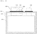
- such a secondary battery is configured to have a structure in which an electrode assembly 20 is mounted in a pouch-type battery case 10 and in which positive and negative electrode tabs 21 and 22 are welded respectively to two electrode leads 31 and 32, which are exposed out of the battery case 10.
- the edge of the case is sealed in the state in which a pair of insulative films 41 is attached to the upper surface and the lower surface of the electrode lead 31 and a pair of insulative films 42 is attached to the upper surface and the lower surface of the electrode lead 32.
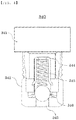
- the gas discharge member 340 may include a body part 342, the body part being provided with a gas movement passageway 343, the interior of which is empty, the gas movement passageway being configured to discharge the gas generated in the pouch-type case 200 to the outside, a spring 345 located in the gas movement passageway 343, and a ball 346 configured to open and close the gas movement passageway 343 while moving vertically or horizontally in the state of abutting the spring 345.
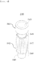
- one side of the groove channel 349 located in the inward direction of the pouch-type case 200 may not overlap the insulative films 330 such that the gas generated in the pouch-type case 200 is introduced into the groove channel 349.
- the concave and convex portion 347 may be provided only at a portion of the outer surface of the body part 342.
- a non-concave and non-convex portion 348 may be provided at a predetermined position of the body part 342 that is directed to the outside of the pouch-type case 200, the non-concave and non-convex portion being located so as to overlap the insulative films 330.
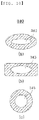
- the body part 342 may have any one of a circular section, an oval section, and a quadrangular section.
- the pouch-type secondary battery according to the present invention may be applied to a battery module including a pouch-type secondary battery.
- the pouch-type secondary battery includes an electrode assembly 100, a pouch-type case 200, and a lead member 300.
- the material for the inner layer may be selected from among a polyolefin-based resin, such as polypropylene, polyethylene, polyethylene acrylate, or polybutylene, a polyurethane resin, and a polyimide resin, which exhibit excellent chemical resistance and good sealability.
- a polyolefin-based resin such as polypropylene, polyethylene, polyethylene acrylate, or polybutylene
- a polyurethane resin such as polyethylene, polyethylene acrylate, or polybutylene
- a polyurethane resin such as polyethylene acrylate
- polybutylene such as polybutylene
- a polyurethane resin such as polyurethane resin
- polyimide resin which exhibit excellent chemical resistance and good sealability.
- Polypropylene which exhibits excellent mechanical properties, such as tensile strength, rigidity, surface hardness, and impact resistance, as well as excellent chemical resistance, is the most preferable.
- the metal layer which abuts the inner layer, corresponds to a barrier layer configured to prevent the permeation of moisture or various kinds of gases from the outside into the battery.
- An aluminum thin film which is lightweight and exhibits excellent formability, may be used as a preferred material for the metal layer.
- the case 200 of the present invention described above may be manufactured in various manners.
- respective films of an inner layer, a metal layer, and an outer layer may be sequentially stacked, and may then be laminated to each other using dry lamination or extrusion lamination, whereby the case may be manufactured.
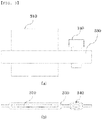
- a pair of insulative films 330 which face each other, is located in the region of the sealed portion 210 at which the positive electrode lead 310 and the negative electrode lead 320 are located, and the positive and negative electrode leads 310 and 320 are disposed so as to extend through between the insulative films 330.
- the gas discharge member 340 may be configured to have an approximate "T" shape including a head part 341 and a body part 342.
- the head part 341 may be omitted, whereby the gas discharge member may include only the body part 342.
- the body part 342 is provided with a gas movement passageway 343 having a predetermined inner diameter such that the gas generated in the pouch-type case 200 is movable therethrough, and a spring 345 having an outer diameter slightly less than the inner diameter of the gas movement passageway is located such that one side of the spring is caught by a catching protrusion 344 provided in the vicinity of the opening side of the gas movement passageway 343 in such a manner that the movement of the spring is restricted.
- a ball 346 configured to open and close the gas movement passageway 343 is provided at the other side of the spring 345.
Abstract
Description
- This application claims the benefit of priority to Korean Patent Application No.
2018-0046719 filed on April 23, 2018 - The present invention relates to a pouch-type secondary battery, and more particularly to a pouch-type secondary battery having a gas discharge means, wherein the gas discharge means is provided between a pair of insulative films, the gas discharge means being configured to discharge gas, whereby the swelling phenomenon and explosion of the battery are prevented.
- As mobile devices have been continuously developed and the demand for mobile devices has increased, secondary batteries, which are capable of being charged and discharged, have been used as energy sources for various mobile devices. In addition, secondary batteries have also attracted considerable attention as energy sources for electric vehicles and hybrid electric vehicles, which have been presented as alternatives to existing gasoline and diesel vehicles using fossil fuels.
- Based on the shape of a battery case, secondary batteries are classified into a cylindrical battery having an electrode assembly mounted in a cylindrical metal can, a prismatic battery having an electrode assembly mounted in a prismatic metal can, and a pouch-type battery having an electrode assembly mounted in a pouch-type case made of an aluminum laminate sheet.
- The electrode assembly, which is mounted in the battery case, is a power generating element that is configured to have a structure including a positive electrode, a negative electrode, and a separator that is interposed between the positive electrode and the negative electrode and that can be charged and discharged. The electrode assembly is classified as a jelly-roll type electrode assembly, which is configured to have a structure in which a long sheet type positive electrode and a long sheet type negative electrode, to which active materials are applied, are wound in the state in which a separator is disposed between the positive electrode and the negative electrode, or a stacked type electrode assembly, which is configured to have a structure in which a plurality of positive electrodes having a predetermined size and a plurality of negative electrodes having a predetermined size are sequentially stacked in the state in which separators are disposed respectively between the positive electrodes and the negative electrodes. The jelly-roll type electrode assembly has advantages in that it is easy to manufacture the jelly-roll type electrode assembly and in that the jelly-roll type electrode assembly has high energy density per unit weight.
- As shown in
FIG. 1 , such a secondary battery is configured to have a structure in which anelectrode assembly 20 is mounted in a pouch-type battery case 10 and in which positive andnegative electrode tabs battery case 10. In general, the edge of the case is sealed in the state in which a pair ofinsulative films 41 is attached to the upper surface and the lower surface of theelectrode lead 31 and a pair ofinsulative films 42 is attached to the upper surface and the lower surface of theelectrode lead 32. - Meanwhile, a secondary battery is charged and discharged through a process in which lithium ions from a lithium metal oxide of a positive electrode are repeatedly intercalated into a negative electrode, such as a graphite electrode, and the lithium ions are repeatedly deintercalated from the negative electrode. However, heat may be generated from such a secondary battery in the event of a short circuit in the secondary battery due to an external impact, overcharge of the secondary battery, or overdischarge of the secondary battery. As a result, an electrolyte may be decomposed in the secondary battery, and thermal runaway may occur in the secondary battery. That is, the safety of the secondary battery is compromised in several aspects. In particular, when the secondary battery is repeatedly charged and discharged, the electrolyte and an electrode active material electrochemically react with each other, and the explosion of the battery due to gas generated as the result of this electrochemical reaction has been noted as a very serious problem.
- As an example of the conventional art for solving the above problem, Korean Patent Application Publication No.
2013-0048419 - In order to open the safety vent, however, the internal temperature of the battery must necessarily increase. Furthermore, it is necessary to separately manufacture an alloy that is fusible at a required temperature. For these reasons, it is impossible to securely prevent the explosion of the battery, and in addition, manufacturing costs are inevitably increased.
- (Patent Document 0001) Korean Patent Application Publication No.
2013-0048419 - The present invention has been made in view of the above problems, and it is an object of the present invention to provide a pouch-type secondary battery having a gas discharge means capable of securely discharging the gas generated in the battery to the outside.
- It is another object of the present invention to provide a pouch-type secondary battery having a gas discharge means, wherein an increase in the cost of manufacturing the battery is minimized and the safety of the battery is secured.
- In accordance with the present invention, the above and other objects can be accomplished by the provision of a pouch-type secondary battery having a gas discharge means, the pouch-type secondary battery including an
electrode assembly 100 including a positive electrode, a negative electrode, and a separator interposed between the positive electrode and the negative electrode, a pouch-type case 200 configured to wrap around theelectrode assembly 100, a pair ofinsulative films 330 disposed in a predetermined region of the edge of the pouch-type case 200 so as to face each other, apositive electrode lead 310, one side of which is electrically connected to a positive electrode current collector of theelectrode assembly 100 and the other side of which protrudes out of the pouch-type case 200 through between theinsulative films 330, anegative electrode lead 320, one side of which is electrically connected to a negative electrode current collector of theelectrode assembly 100 and the other side of which protrudes out of the pouch-type case 200 through between theinsulative films 330, and agas discharge member 340 interposed between theinsulative films 330, the gas discharge member being configured to discharge the gas generated in the pouch-type case 200 to the outside. - Also, in the pouch-type secondary battery according to the present invention, the
gas discharge member 340 may include abody part 342, the body part being provided with agas movement passageway 343, the interior of which is empty, the gas movement passageway being configured to discharge the gas generated in the pouch-type case 200 to the outside, aspring 345 located in thegas movement passageway 343, and aball 346 configured to open and close thegas movement passageway 343 while moving vertically or horizontally in the state of abutting thespring 345. - Also, in the pouch-type secondary battery according to the present invention, a concave and
convex portion 347 may be provided at the outer surface of thebody part 342. - Also, in the pouch-type secondary battery according to the present invention, the concave and
convex portion 347 may include at least onegroove channel 349 formed in the longitudinal direction of thebody part 342. - Also, in the pouch-type secondary battery according to the present invention, one side of the
groove channel 349 located in the inward direction of the pouch-type case 200 may not overlap theinsulative films 330 such that the gas generated in the pouch-type case 200 is introduced into thegroove channel 349. - Also, in the pouch-type secondary battery according to the present invention, the concave and
convex portion 347 may be provided only at a portion of the outer surface of thebody part 342. - Also, in the pouch-type secondary battery according to the present invention, the concave and
convex portion 347 may be provided in the longitudinal direction of thebody part 342, and a non-concave andnon-convex portion 348 may be provided at a predetermined position of the body part that is directed to the outside of the pouch-type case 200. - Also, in the pouch-type secondary battery according to the present invention, one side of the
groove channel 349, located in the inward direction of the pouch-type case, may not overlap theinsulative films 330, and the other side of thegroove channel 349, at which the non-concave andnon-convex portion 348 is provided, may overlap theinsulative films 330 such that the gas generated in the pouch-type case 200 is introduced into thegroove channel 349. - Also, in the pouch-type secondary battery according to the present invention, a portion of the
groove channel 349 that is located in the inward direction of the pouch-type case 200 may communicate with the interior of the pouch-type case 200 such that the gas generated in the pouch-type case 200 is introduced into thegroove channel 349. - Also, in the pouch-type secondary battery according to the present invention, a non-concave and
non-convex portion 348 may be provided at a predetermined position of thebody part 342 that is directed to the outside of the pouch-type case 200, the non-concave and non-convex portion being located so as to overlap theinsulative films 330. - Also, in the pouch-type secondary battery according to the present invention, the
body part 342 may have any one of a circular section, an oval section, and a quadrangular section. - Also, in the pouch-type secondary battery according to the present invention, the
gas discharge member 340 may be made of metal or plastic. - The pouch-type secondary battery according to the present invention may be applied to a battery module including a pouch-type secondary battery.
- In addition, the battery module may be applied to a battery pack including a battery module.
-
-
FIG. 1 is an exploded perspective view showing a conventional pouch-type secondary battery. -
FIG. 2 is a front view showing a pouch-type secondary battery having a gas discharge means according to a preferred embodiment of the present invention. -
FIG. 3(a) is an enlarged front view showing a principal part of the pouch-type secondary battery shown inFIG. 2 , andFIG. 3(b) is a plan view thereof. -
FIG. 4 is a sectional view illustrating the interior structure of a gas discharge member according to a preferred embodiment of the present invention. -
FIGS. 5 and6 are perspective views respectively illustrating the exterior structures of gas discharge members according to first and second modifications of the present invention. -
FIG. 7 is a view showing a first embodiment illustrating the state in which the gas discharge member shown inFIG. 5 and insulative films are joined to each other. -
FIG. 8 is a view showing a second embodiment illustrating the state in which the gas discharge member shown inFIG. 5 and the insulative films are joined to each other. -
FIG. 9 is a view showing a third embodiment illustrating the state in which the gas discharge member shown inFIG. 5 and the insulative films are joined to each other. -
FIG. 10 is a view showing the sectional shape of the gas discharge member. -
FIG. 11 is a view showing the state in which the gas discharge member and the insulative films are joined to each other based on a deformed lead member. - In the present application, it should be understood that the terms "comprises," "has," or "includes," etc. specify the presence of features, integers, steps, operations, components, parts, or combinations thereof described in the specification, but do not preclude the presence or addition of one or more other features, integers, steps, operations, components, parts, or combinations thereof.
- In addition, the same reference numbers will be used throughout the drawings to refer to parts that perform similar functions or operations. In the case in which one part is said to be connected to another part in the specification, not only may the one part be directly connected to the another part, but also, the one part may be indirectly connected to the another part via a further part. In addition, that a certain element is included does not mean that other elements are excluded, but means that such elements may be further included unless mentioned otherwise.
- Hereinafter, a pouch-type secondary battery having a gas discharge means according to the present invention will be described with reference to the accompanying drawings.
-
FIG. 2 is a front view showing a pouch-type secondary battery having a gas discharge means according to a preferred embodiment of the present invention,FIG. 3(a) is an enlarged front view showing a principal part of the pouch-type secondary battery shown inFIG. 2 , andFIG. 3(b) is a plan view thereof. - Referring to
FIGS. 2 and3 , the pouch-type secondary battery according to the preferred embodiment of the present invention includes anelectrode assembly 100, a pouch-type case 200, and alead member 300. - The
electrode assembly 100 may be a jelly-roll type electrode assembly, which is configured to have a structure in which a long sheet type positive electrode and a long sheet type negative electrode are wound in the state in which a separator is interposed between the positive electrode and the negative electrode, a stacked type electrode assembly including unit cells, each of which is configured to have a structure in which a rectangular positive electrode and a rectangular negative electrode are stacked in the state in which a separator is interposed between the positive electrode and the negative electrode, a stack/folded type electrode assembly, which is configured to have a structure in which the unit cells are wound in the state in which the unit cells are disposed on a long separation film, or a laminated/stacked type electrode assembly, which is configured to have a structure in which the unit cells are stacked so as to be attached to each other in the state in which a separator is interposed between the unit cells. However, the present invention is not limited thereto. - The pouch-
type case 200 is a case configured to receive theelectrode assembly 100, and is generally configured to have a laminate sheet structure including an inner layer, a metal layer, and an outer layer. - The inner layer directly contacts the
electrode assembly 100. For this reason, it is necessary for the inner layer to exhibit an insulation property and resistance to an electrolytic solution. In addition, for isolation from the outside, it is necessary for the inner layer to exhibit sealability. That is, it is necessary for a sealed portion, formed by thermally adhering inner layers, to exhibit excellent thermal adhesive strength. - The material for the inner layer may be selected from among a polyolefin-based resin, such as polypropylene, polyethylene, polyethylene acrylate, or polybutylene, a polyurethane resin, and a polyimide resin, which exhibit excellent chemical resistance and good sealability. However, the present invention is not limited thereto. Polypropylene, which exhibits excellent mechanical properties, such as tensile strength, rigidity, surface hardness, and impact resistance, as well as excellent chemical resistance, is the most preferable.
- The metal layer, which abuts the inner layer, corresponds to a barrier layer configured to prevent the permeation of moisture or various kinds of gases from the outside into the battery. An aluminum thin film, which is lightweight and exhibits excellent formability, may be used as a preferred material for the metal layer.
- The outer layer is provided at the other surface of the metal layer. The outer layer may be made of a heat-resistant polymer that exhibits excellent tensile strength, moisture permeation prevention capability, and air permeation prevention capability such that the outer layer exhibits heat resistance and chemical resistance while protecting the electrode assembly. In an example, the outer layer may be made of nylon or polyethylene terephthalate. However, the present invention is not limited thereto.
- The
case 200 of the present invention described above may be manufactured in various manners. For example, respective films of an inner layer, a metal layer, and an outer layer may be sequentially stacked, and may then be laminated to each other using dry lamination or extrusion lamination, whereby the case may be manufactured. - Meanwhile, a sealed
portion 210 formed along the edge of the pouch-type case 200 is formed at all of four side surfaces of the pouch-type case in order to maintain the sealed state of the pouch-type secondary battery. After theelectrode assembly 100 is received in thecase 200, thecase 210 may be thermally fused to form the sealedportion 210. However, it is obvious that the sealedportion 210 may be formed using methods that are usually used in the art to which the present invention pertains. - Leads, which generally include a
positive electrode lead 310 and anegative electrode lead 320, are configured to have a structure in which a positive electrode tab (not shown) and a negative electrode tab (not shown), which are attached to the upper end of theelectrode assembly 100, are electrically connected to thepositive electrode lead 310 and thenegative electrode lead 320, respectively, by welding and in which the leads are exposed out of thecase 200. - At this time, in order to assuredly secure insulativity and sealability, a pair of
insulative films 330, which face each other, is located in the region of the sealedportion 210 at which thepositive electrode lead 310 and thenegative electrode lead 320 are located, and the positive and negative electrode leads 310 and 320 are disposed so as to extend through between theinsulative films 330. - Specifically, pressure becomes relatively high at the portions of the pouch-
type case 200 that contact the positive and negative electrode leads 310 and 320 during the process of sealing the pouch-type case 200, whereby the possibility of the inner layer of the pouch-type case 200 being damaged may be increased. As a result, the pouch-type case 200 may not be securely sealed, which may lead to a defective product. In particular, in the case in which the inner layer of the pouch-type case 200 is damaged at the time of sealing, the metal layer, which directly abuts the inner layer, is directly exposed to the outside. The exposed portion of the metal layer may electrically contact the positive and negative electrode leads 310 and 320, whereby the possibility of occurrence of an accident, such as a short circuit, may be high. - In order to prevent the occurrence of poor sealing, which may be caused at the time of sealing the pouch-
type case 200, as described above, and to secure electrical insulativity, therefore, a pair ofinsulative films 330 is located on the upper surface and the lower surface of each of thepositive electrode lead 310 and thenegative electrode lead 320. - Here, the material for the
insulative films 330 may be one of a thermoplastic resin, a thermosetting resin, and a photo-curing resin, which exhibit electrical insulativity. For example, the material for the insulative films may be a styrene-butadiene resin, a styrene resin, an epoxy resin, a urethane resin, an acrylic-based resin, a phenol resin, an amide-based resin, an acrylate-based resin, or a denatured resin thereof. However, the material for the insulative films is not particularly restricted, as long as the material is a resin that is capable of performing the above functions. - Between the pair of
insulative films 330 is interposed agas discharge member 340 configured to discharge the gas generated in the pouch-type case 200 to the outside. One side of thegas discharge member 340 is located in the pouch-type case 200, and the other side of thegas discharge member 340 protrudes out of theinsulative films 330. As previously described, a swelling phenomenon, in which gas, such as carbon dioxide or carbon monoxide, is generated in the secondary battery due to various kinds of causes, such as repeated charging and discharging, overcharging, or the occurrence of a short circuit, whereby the case swells, may occur in the battery. Depending on the circumstances, the battery may even explode. - The
gas discharge member 340 is configured to discharge the gas generated in the pouch-type case 200 of the battery, as described above, to the outside. The interior structure of a gas discharge member according to a preferred embodiment of the present invention will be described in detail with reference toFIG. 4 , which is a sectional view illustrating the interior structure of the gas discharge member. - The
gas discharge member 340 according to the preferred embodiment of the present invention may be configured to have an approximate "T" shape including ahead part 341 and abody part 342. Alternatively, thehead part 341 may be omitted, whereby the gas discharge member may include only thebody part 342. - The
body part 342 is provided with agas movement passageway 343 having a predetermined inner diameter such that the gas generated in the pouch-type case 200 is movable therethrough, and aspring 345 having an outer diameter slightly less than the inner diameter of the gas movement passageway is located such that one side of the spring is caught by a catchingprotrusion 344 provided in the vicinity of the opening side of thegas movement passageway 343 in such a manner that the movement of the spring is restricted. In addition, aball 346 configured to open and close thegas movement passageway 343 is provided at the other side of thespring 345. - According to the
gas discharge member 340 having the above construction, when the pressure in the pouch-type case 200 reaches a predetermined level, theball 345 pushes thespring 345 upwards. As a result, the generated gas is discharged to the outside through thegas movement passageway 343, whereby the occurrence of a swelling phenomenon or the explosion of the battery may be prevented. Furthermore, in the case in which the generation of gas is caused by a temporary phenomenon, thespring 345 is restored, whereby theball 345 closes thegas movement passageway 343 again. Consequently, it is possible to continuously use the secondary battery. -
FIGS. 5 and6 are perspective views respectively illustrating the exterior structures of gas discharge members according to first and second modifications of the present invention, andFIG. 7 is a view showing a first embodiment illustrating the state in which the gas discharge member shown inFIG. 5 and the insulative films are joined to each other. - The gas discharge member according to each of the modifications of the present invention is identical to the
gas discharge member 340 shown inFIG. 4 in terms of the inner structure thereof, such as thegas movement passageway 343, the catchingprotrusion 344, thespring 345, and theball 346, and is different from the gas discharge member shown inFIG. 4 only in terms of the external shape of thebody part 342. Hereinafter, therefore, only the external shape of the body part will be described in detail. - The
gas discharge member 340 according to each of the modifications of the present invention has a concave andconvex portion 347 formed at a predetermined region of the outer surface of thebody part 342. Specifically, as shown inFIGS. 5 and6 , a concave andconvex portion 347, having at least onegroove channel 349 formed in the longitudinal direction of thebody part 342 such that gas is movable therealong, is preferably provided at the middle region of the outer surface of thebody part 342, and smooth surfaces, i.e. non-concave andnon-convex portions 348, are more preferably formed at the upper portion and the lower portion of thebody part 342 such that the concave andconvex portion 347 is located between the non-concave and non-convex portions. - In addition, as shown in
FIG. 7 , one end of thegroove channel 349, which is directed inwards, is located on the same line as the lower edge of each of theinsulative films 330 such that the gas generated in the pouch-type case 200 is introduced into thegas discharge member 340 having the concave andconvex portion 347 formed between the non-concave andnon-convex portions 348 described above. - Since the
gas discharge member 340, having the concave andconvex portion 347 and the non-concave andnon-convex portions 348 provided at the outer surface of thebody part 342, is interposed between theinsulative films 330, as described above, it is possible to securely prevent the explosion of the secondary battery due to swelling. Since thegas discharge member 340 includes theball 346 and thespring 345 in thegas movement passageway 343, as previously described, thegas discharge member 340 is capable of discharging gas to the outside when the pressure in the pouch-type case 200 reaches a predetermined level. However, the gas may not be discharged, and thus the pouch-type case may continuously swell due to the malfunction of theball 346 or thespring 345. In particular, when a large amount of gas is continuously discharged, it is possible to prevent the explosion of the battery only in the case in which the sectional area of thegas movement passageway 343 is sufficiently large. Since the outer diameter of thegas discharge member 340 is preferably several tens of mm or less, more specifically 20 mm or less, in consideration of the characteristics of the secondary battery, however, restrictions are inevitably involved. - In contrast, as shown in
FIG. 7 , theinsulative films 330 wrap around the protruding region of the concave andconvex portion 347 in the state of being attached to the protruding region of the concave andconvex portion 347, a groove channel inlet 349', which is directed to the inside of the pouch-type case 200, communicates with the interior of the pouch-type case 200, and theinsulative films 330 tightly contact the surface of the non-concave andnon-convex portion 348 that is directed to the outside of the pouch-type case 200. Even in the case in which the pressure in the pouch-type case 200 abruptly increases, therefore, the gas introduced through the groove channel inlet 349' moves along thegroove channel 349, and the non-concave andnon-convex portion 348 and theinsulative films 330, which have relatively low adhesive force therebetween, are separated from each other first, whereby the gas is discharged to the center of the non-concave andnon-convex portion 348, or thegas discharge member 340 is separated from theinsulative films 330. Consequently, it is possible to prevent the occurrence of a large-scale accident. - Meanwhile, the concave and
convex portion 347 is shown as protruding from the outer surface of thebody part 342 inFIGS. 5 and6 . Alternatively, the concave andconvex portion 347 may be formed in the outer surface of thebody part 342 in a depressed state. - In addition, the
gas discharge member 340 may be made of metal or plastic. More preferably, thegas discharge member 340 is made of metal, which exhibits relatively high sealability. - Next,
FIG. 8 is a view showing a second embodiment illustrating the state in which the gas discharge member shown inFIG. 5 and the insulative films are joined to each other. In the second embodiment, one end of thegroove channel 349 extends below the lower edge of each of theinsulative films 330, i.e. to the interior of thecase 200. According to the second embodiment, a portion of thegroove channel 349, including the groove channel inlet 349', is in a fully open state. As a result, gas is more easily movable, and it is not necessary to accurately align the lower edge of each of theinsulative films 330 with one end of thegroove channel 349, whereby manufacturing is easy. -
FIG. 9 is a view showing a third embodiment illustrating the state in which the gas discharge member shown inFIG. 5 and the insulative films are joined to each other, wherein one end of thegroove channel 349 is located below the lower edge of each of theinsulative films 330, and in addition, one end of thegroove channel 349 extends to the end of thebody part 342. The third embodiment has advantages similar to the advantages of the second embodiment, and therefore a detailed description thereof will be omitted. - Meanwhile, as shown in
FIG. 10 , the section of thegas discharge member 340 may be circular, oval, or quadrangular. -
FIG. 11 is a view showing the state in which the gas discharge member and the insulative films are joined to each other based on a deformed lead member, wherein thepositive electrode lead 310 and/or thenegative electrode lead 320 may be configured in a shape in which the left surface, the right surface, and the upper surface thereof surround thegas discharge member 340. - In the case in which the
gas discharge member 340 is disposed in the above structure, it is possible to minimize loss of the volume of a battery pack even in the case in which thegas discharge member 340 is added, since the positive and negative electrode leads are identical to existing positive and negative electrode leads, whereby it is possible to increase the energy density of the battery pack. Furthermore, thegas discharge member 340 according to the present invention is also applicable to a battery in which thegas discharge member 340 is separately provided. In addition, there is an advantage that manufacturing is possible even though production facilities are not greatly changed. - Although the specific details of the present invention have been described in detail, those skilled in the art will appreciate that the detailed description thereof discloses only preferred embodiments of the present invention and thus does not limit the scope of the present invention. Accordingly, those skilled in the art will appreciate that various changes and modifications are possible, without departing from the category and the technical idea of the present invention, and it will be obvious that such changes and modifications fall within the scope of the appended claims.
-
- 100: Electrode assembly
- 200: Pouch-type case
- 210: Sealed portion
- 300: Lead member
- 310: Positive electrode lead
- 320: Negative electrode lead
- 330: Insulative films
- 340: Gas discharge member
- 341: Head part
- 342: Body part
- 343: Gas movement passageway
- 344: Catching protrusion
- 345: Spring
- 346: Ball
- 347: Concave and convex portion
- 348: Non-concave and non-convex portion
- 349: Groove channel
- 349': Groove channel inlet
- In the pouch-type secondary battery according to the present invention, a gas discharge member is interposed between a pair of insulative films, whereby it is possible to discharge the gas generated in the battery to the outside and thus it is possible to prevent the occurrence of a swelling phenomenon or the explosion of the battery.
- Also, in the pouch-type secondary battery according to the present invention, the gas discharge member, which is interposed between the pair of insulative films, is provided at the outer surface thereof with a concave and convex portion and a non-concave and non-convex portion. Even in the case in which a large amount of gas is generated, the non-concave and non-convex portion and the insulative films, which have relatively low adhesive strength therebetween, are separated from each other, and the gas is discharged to the outside. Consequently, it is possible to remarkably reduce the danger of explosion of the battery.
Claims (14)
- A pouch-type secondary battery having a gas discharge means, the pouch-type secondary battery comprising:an electrode assembly comprising a positive electrode, a negative electrode, and a separator interposed between the positive electrode and the negative electrode;a pouch-type case configured to wrap around the electrode assembly;a pair of insulative films disposed in a predetermined region of an edge of the pouch-type case so as to face each other;a positive electrode lead, one side of which is electrically connected to a positive electrode current collector of the electrode assembly and the other side of which protrudes out of the pouch-type case through between the insulative films;a negative electrode lead, one side of which is electrically connected to a negative electrode current collector of the electrode assembly and the other side of which protrudes out of the pouch-type case through between the insulative films; anda gas discharge member interposed between the insulative films, the gas discharge member being configured to discharge gas generated in the pouch-type case to an outside.
- The pouch-type secondary battery according to claim 1, wherein the gas discharge member comprises a body part, the body part being provided with a gas movement passageway, an interior of which is empty, the gas movement passageway being configured to discharge the gas generated in the pouch-type case to the outside, a spring located in the gas movement passageway, and a ball configured to open and close the gas movement passageway while moving vertically or horizontally in a state of abutting the spring.
- The pouch-type secondary battery according to claim 2, wherein the body part is further provided with a concave and convex portion, which is formed at an outer surface thereof.
- The pouch-type secondary battery according to claim 3, wherein the concave and convex portion comprises at least one groove channel formed in a longitudinal direction of the body part.
- The pouch-type secondary battery according to claim 4, wherein one side of the groove channel located in an inward direction of the pouch-type case does not overlap the insulative films such that the gas generated in the pouch-type case is introduced into the groove channel.
- The pouch-type secondary battery according to claim 3, wherein the concave and convex portion is provided only at a portion of the outer surface of the body part.
- The pouch-type secondary battery according to claim 6, wherein the concave and convex portion is provided in a longitudinal direction of the body part, and wherein a non-concave and non-convex portion is provided at a predetermined position of the body part that is directed to an outside of the pouch-type case.
- The pouch-type secondary battery according to claim 7, wherein one side of the groove channel, located in an inward direction of the pouch-type case, does not overlap the insulative films, and the other side of the groove channel, at which the non-concave and non-convex portion is provided, overlaps the insulative films such that the gas generated in the pouch-type case is introduced into the groove channel.
- The pouch-type secondary battery according to claim 4, wherein a portion of the groove channel that is located in an inward direction of the pouch-type case communicates with an interior of the pouch-type case such that the gas generated in the pouch-type case is introduced into the groove channel.
- The pouch-type secondary battery according to claim 9, wherein a non-concave and non-convex portion is provided at a predetermined position of the body part that is directed to an outside of the pouch-type case, the non-concave and non-convex portion being located so as to overlap the insulative films.
- The pouch-type secondary battery according to claim 2, wherein the body part has any one of a circular section, an oval section, and a quadrangular section.
- The pouch-type secondary battery according to claim 2, wherein the gas discharge member is made of metal or plastic.
- A battery module comprising the pouch-type secondary battery according to any one of claims 1 to 12.
- A battery pack comprising the battery module according to claim 13.
Applications Claiming Priority (2)
| Application Number | Priority Date | Filing Date | Title |
|---|---|---|---|
| KR1020180046749A KR102361569B1 (en) | 2018-04-23 | 2018-04-23 | Pouch Type Secondary Battery With Gas Venting Means |
| PCT/KR2019/001034 WO2019208911A1 (en) | 2018-04-23 | 2019-01-24 | Pouch-type secondary battery having gas discharge means |
Publications (2)
| Publication Number | Publication Date |
|---|---|
| EP3671898A1 true EP3671898A1 (en) | 2020-06-24 |
| EP3671898A4 EP3671898A4 (en) | 2020-12-09 |
Family
ID=68294610
Family Applications (1)
| Application Number | Title | Priority Date | Filing Date |
|---|---|---|---|
| EP19792234.7A Pending EP3671898A4 (en) | 2018-04-23 | 2019-01-24 | Pouch-type secondary battery having gas discharge means |
Country Status (6)
| Country | Link |
|---|---|
| US (1) | US11177532B2 (en) |
| EP (1) | EP3671898A4 (en) |
| JP (1) | JP7049541B2 (en) |
| KR (1) | KR102361569B1 (en) |
| CN (1) | CN111033799B (en) |
| WO (1) | WO2019208911A1 (en) |
Families Citing this family (15)
| Publication number | Priority date | Publication date | Assignee | Title |
|---|---|---|---|---|
| KR102341465B1 (en) * | 2018-05-10 | 2021-12-22 | 주식회사 엘지에너지솔루션 | The Apparatus For Venting And The Method For Manufacturing Thereof |
| KR20210051733A (en) * | 2019-10-31 | 2021-05-10 | 에스케이이노베이션 주식회사 | Pouch Type Secondary Battery And Production Method Thereof |
| KR20210139082A (en) * | 2020-05-13 | 2021-11-22 | 주식회사 엘지에너지솔루션 | Rechargeable battery |
| KR20210155279A (en) * | 2020-06-15 | 2021-12-22 | 주식회사 엘지에너지솔루션 | Secondary battery |
| KR20220007437A (en) * | 2020-07-10 | 2022-01-18 | 주식회사 엘지에너지솔루션 | Rechargeable battery |
| US20230084670A1 (en) * | 2020-11-06 | 2023-03-16 | Lg Energy Solution, Ltd. | Battery Cell and Battery Module Including the Same |
| EP4170800A4 (en) | 2020-12-08 | 2024-04-17 | Lg Energy Solution Ltd | Secondary battery and battery module including same |
| KR20220101578A (en) * | 2021-01-11 | 2022-07-19 | 주식회사 엘지에너지솔루션 | Battery cell and battery module including the same |
| KR20220107611A (en) * | 2021-01-25 | 2022-08-02 | 주식회사 엘지에너지솔루션 | Venting device for secondary battery and pouch type secondary battery having the same |
| KR20220109333A (en) * | 2021-01-28 | 2022-08-04 | 주식회사 엘지에너지솔루션 | Battery cell and battery cell manufacturing device |
| US20220336917A1 (en) * | 2021-04-14 | 2022-10-20 | Lg Energy Solution, Ltd. | Secondary Battery |
| US20220336914A1 (en) * | 2021-04-15 | 2022-10-20 | Lg Energy Solution, Ltd. | Secondary Battery |
| KR20230025140A (en) * | 2021-08-13 | 2023-02-21 | 주식회사 엘지에너지솔루션 | Pouch bag for secondary battery and pouch type secondary battery |
| KR20230071273A (en) | 2021-11-16 | 2023-05-23 | 주식회사 엘지에너지솔루션 | Venting device and secondary battery comprising it |
| DE102022200014A1 (en) | 2022-01-04 | 2023-07-06 | Volkswagen Aktiengesellschaft | Safety device for arrangement in a cell wall of a battery cell, battery cell, battery module and manufacturing method for a battery cell |
Family Cites Families (16)
| Publication number | Priority date | Publication date | Assignee | Title |
|---|---|---|---|---|
| KR19980060805A (en) | 1996-12-31 | 1998-10-07 | 손욱 | Cap assembly of battery |
| JP4867158B2 (en) | 2004-11-19 | 2012-02-01 | トヨタ自動車株式会社 | Film exterior power storage device |
| US8071231B2 (en) * | 2006-08-28 | 2011-12-06 | Lg Chem, Ltd. | Secondary battery including one-way exhaust valve |
| CN101651194A (en) * | 2008-08-14 | 2010-02-17 | 上海比亚迪有限公司 | Lithium ion battery |
| KR101049820B1 (en) | 2008-08-04 | 2011-07-15 | 삼성에스디아이 주식회사 | Secondary battery |
| KR101245284B1 (en) * | 2010-12-20 | 2013-03-19 | 주식회사 엘지화학 | Secondary battery capable of re-injecting electrolyte |
| KR20130048419A (en) | 2011-11-02 | 2013-05-10 | 에스케이이노베이션 주식회사 | Secondary battery in pouch type |
| KR101908583B1 (en) * | 2012-06-28 | 2018-10-17 | 에스케이이노베이션 주식회사 | Secondary battery module available for easy gathering and discharging of gas |
| KR101268296B1 (en) * | 2012-11-16 | 2013-05-28 | 주식회사 유니크 | Vent cap for battery |
| KR102257850B1 (en) | 2014-07-18 | 2021-05-28 | 에스케이이노베이션 주식회사 | Pouch type lithium secondary battery having tubular passage structure |
| KR102275273B1 (en) | 2014-07-29 | 2021-07-09 | 에스케이이노베이션 주식회사 | Venting system of pouch type lithium secondary battery |
| DE102014018751A1 (en) * | 2014-12-16 | 2016-06-16 | Daimler Ag | Electrochemical energy storage and battery |
| KR20160102615A (en) * | 2015-02-23 | 2016-08-31 | 박준혁 | Bi-directional piston pump unit for high efficiency recuperative pesticide sprayer |
| KR102318043B1 (en) * | 2015-04-22 | 2021-10-28 | 에스케이이노베이션 주식회사 | Secondary battery and battery module having the same |
| KR101904587B1 (en) * | 2015-09-01 | 2018-10-04 | 주식회사 엘지화학 | Battery cell and method for manufacturing the same |
| KR101877534B1 (en) | 2016-10-28 | 2018-07-11 | 주종문 | Sprayed water culture platform assembly for mounting plant husbandry bed |
-
2018
- 2018-04-23 KR KR1020180046749A patent/KR102361569B1/en active IP Right Grant
-
2019
- 2019-01-24 US US16/753,442 patent/US11177532B2/en active Active
- 2019-01-24 JP JP2020515721A patent/JP7049541B2/en active Active
- 2019-01-24 CN CN201980003936.0A patent/CN111033799B/en active Active
- 2019-01-24 EP EP19792234.7A patent/EP3671898A4/en active Pending
- 2019-01-24 WO PCT/KR2019/001034 patent/WO2019208911A1/en unknown
Also Published As
| Publication number | Publication date |
|---|---|
| WO2019208911A1 (en) | 2019-10-31 |
| CN111033799B (en) | 2022-03-25 |
| JP7049541B2 (en) | 2022-04-07 |
| US20200321577A1 (en) | 2020-10-08 |
| KR102361569B1 (en) | 2022-02-10 |
| US11177532B2 (en) | 2021-11-16 |
| JP2020534650A (en) | 2020-11-26 |
| EP3671898A4 (en) | 2020-12-09 |
| CN111033799A (en) | 2020-04-17 |
| KR20190123059A (en) | 2019-10-31 |
Similar Documents
| Publication | Publication Date | Title |
|---|---|---|
| US11177532B2 (en) | Pouch-type secondary battery having gas discharge means | |
| US7718306B2 (en) | Rechargeable battery with gas release safety vent | |
| CN101663779B (en) | Battery cell of improved safety | |
| KR100973310B1 (en) | Electrode tab for secondary battery and secondary battery using the same | |
| CN110088944B (en) | Pouch-shaped secondary battery including electrode lead using conductive polymer | |
| US20170047565A1 (en) | Secondary battery | |
| CN101540381A (en) | Cap assembly and secondary battery using the same | |
| US20090092897A1 (en) | Cap assembly and secondary battery using the same | |
| US20110143177A1 (en) | Secondary battery and manufacturing method thereof | |
| JP7146335B2 (en) | venting device | |
| KR101273472B1 (en) | Manufacturing method for pouch-type secondary battery and pouch-type secondary battery made by the same | |
| EP3998674A1 (en) | Secondary battery | |
| US20230048711A1 (en) | Battery Cell with Improved Safety and Method of Manufacturing the Same | |
| US10535859B2 (en) | Pouch-shaped secondary battery including micro-perforated electrode lead having adhesive properties | |
| KR20060112746A (en) | Cap assembly and lithium ion secondary battery with the same | |
| US20230420792A1 (en) | Pouch-Shaped Battery Cell With Improved Safety | |
| EP4243194A1 (en) | Pouch-type battery cell with improved thermal stability | |
| EP4164043A1 (en) | Pouch-type battery cell comprising sealing portion venting controlling means | |
| EP4290673A1 (en) | Secondary battery | |
| KR20060059713A (en) | Cap assembly and lithium secondary battery with the same |
Legal Events
| Date | Code | Title | Description |
|---|---|---|---|
| STAA | Information on the status of an ep patent application or granted ep patent |
Free format text: STATUS: THE INTERNATIONAL PUBLICATION HAS BEEN MADE |
|
| PUAI | Public reference made under article 153(3) epc to a published international application that has entered the european phase |
Free format text: ORIGINAL CODE: 0009012 |
|
| STAA | Information on the status of an ep patent application or granted ep patent |
Free format text: STATUS: REQUEST FOR EXAMINATION WAS MADE |
|
| 17P | Request for examination filed |
Effective date: 20200317 |
|
| AK | Designated contracting states |
Kind code of ref document: A1 Designated state(s): AL AT BE BG CH CY CZ DE DK EE ES FI FR GB GR HR HU IE IS IT LI LT LU LV MC MK MT NL NO PL PT RO RS SE SI SK SM TR |
|
| AX | Request for extension of the european patent |
Extension state: BA ME |
|
| A4 | Supplementary search report drawn up and despatched |
Effective date: 20201109 |
|
| RIC1 | Information provided on ipc code assigned before grant |
Ipc: H01M 2/06 20060101ALI20201103BHEP Ipc: H01M 2/12 20060101AFI20201103BHEP Ipc: H01M 2/30 20060101ALI20201103BHEP Ipc: H01M 2/02 20060101ALI20201103BHEP |
|
| DAV | Request for validation of the european patent (deleted) | ||
| DAX | Request for extension of the european patent (deleted) | ||
| RAP1 | Party data changed (applicant data changed or rights of an application transferred) |
Owner name: LG ENERGY SOLUTION LTD. |
|
| RAP3 | Party data changed (applicant data changed or rights of an application transferred) |
Owner name: LG ENERGY SOLUTION, LTD. |