EP3671806B1 - Magnetron-sputterkathodenanordnung für eine sputtervorrichtung mit ungleichmässigem magnetron - Google Patents
Magnetron-sputterkathodenanordnung für eine sputtervorrichtung mit ungleichmässigem magnetron Download PDFInfo
- Publication number
- EP3671806B1 EP3671806B1 EP18214105.1A EP18214105A EP3671806B1 EP 3671806 B1 EP3671806 B1 EP 3671806B1 EP 18214105 A EP18214105 A EP 18214105A EP 3671806 B1 EP3671806 B1 EP 3671806B1
- Authority
- EP
- European Patent Office
- Prior art keywords
- magnetron sputtering
- target
- cathode assembly
- sputtering cathode
- cooler
- Prior art date
- Legal status (The legal status is an assumption and is not a legal conclusion. Google has not performed a legal analysis and makes no representation as to the accuracy of the status listed.)
- Active
Links
Images

Classifications
-
- H—ELECTRICITY
- H01—ELECTRIC ELEMENTS
- H01J—ELECTRIC DISCHARGE TUBES OR DISCHARGE LAMPS
- H01J37/00—Discharge tubes with provision for introducing objects or material to be exposed to the discharge, e.g. for the purpose of examination or processing thereof
- H01J37/32—Gas-filled discharge tubes
- H01J37/34—Gas-filled discharge tubes operating with cathodic sputtering
- H01J37/3411—Constructional aspects of the reactor
- H01J37/3461—Means for shaping the magnetic field, e.g. magnetic shunts
-
- C—CHEMISTRY; METALLURGY
- C23—COATING METALLIC MATERIAL; COATING MATERIAL WITH METALLIC MATERIAL; CHEMICAL SURFACE TREATMENT; DIFFUSION TREATMENT OF METALLIC MATERIAL; COATING BY VACUUM EVAPORATION, BY SPUTTERING, BY ION IMPLANTATION OR BY CHEMICAL VAPOUR DEPOSITION, IN GENERAL; INHIBITING CORROSION OF METALLIC MATERIAL OR INCRUSTATION IN GENERAL
- C23C—COATING METALLIC MATERIAL; COATING MATERIAL WITH METALLIC MATERIAL; SURFACE TREATMENT OF METALLIC MATERIAL BY DIFFUSION INTO THE SURFACE, BY CHEMICAL CONVERSION OR SUBSTITUTION; COATING BY VACUUM EVAPORATION, BY SPUTTERING, BY ION IMPLANTATION OR BY CHEMICAL VAPOUR DEPOSITION, IN GENERAL
- C23C14/00—Coating by vacuum evaporation, by sputtering or by ion implantation of the coating forming material
- C23C14/22—Coating by vacuum evaporation, by sputtering or by ion implantation of the coating forming material characterised by the process of coating
- C23C14/34—Sputtering
- C23C14/3407—Cathode assembly for sputtering apparatus, e.g. Target
-
- C—CHEMISTRY; METALLURGY
- C23—COATING METALLIC MATERIAL; COATING MATERIAL WITH METALLIC MATERIAL; CHEMICAL SURFACE TREATMENT; DIFFUSION TREATMENT OF METALLIC MATERIAL; COATING BY VACUUM EVAPORATION, BY SPUTTERING, BY ION IMPLANTATION OR BY CHEMICAL VAPOUR DEPOSITION, IN GENERAL; INHIBITING CORROSION OF METALLIC MATERIAL OR INCRUSTATION IN GENERAL
- C23C—COATING METALLIC MATERIAL; COATING MATERIAL WITH METALLIC MATERIAL; SURFACE TREATMENT OF METALLIC MATERIAL BY DIFFUSION INTO THE SURFACE, BY CHEMICAL CONVERSION OR SUBSTITUTION; COATING BY VACUUM EVAPORATION, BY SPUTTERING, BY ION IMPLANTATION OR BY CHEMICAL VAPOUR DEPOSITION, IN GENERAL
- C23C14/00—Coating by vacuum evaporation, by sputtering or by ion implantation of the coating forming material
- C23C14/22—Coating by vacuum evaporation, by sputtering or by ion implantation of the coating forming material characterised by the process of coating
- C23C14/34—Sputtering
- C23C14/35—Sputtering by application of a magnetic field, e.g. magnetron sputtering
-
- H—ELECTRICITY
- H01—ELECTRIC ELEMENTS
- H01J—ELECTRIC DISCHARGE TUBES OR DISCHARGE LAMPS
- H01J37/00—Discharge tubes with provision for introducing objects or material to be exposed to the discharge, e.g. for the purpose of examination or processing thereof
- H01J37/32—Gas-filled discharge tubes
- H01J37/32431—Constructional details of the reactor
- H01J37/3244—Gas supply means
-
- H—ELECTRICITY
- H01—ELECTRIC ELEMENTS
- H01J—ELECTRIC DISCHARGE TUBES OR DISCHARGE LAMPS
- H01J37/00—Discharge tubes with provision for introducing objects or material to be exposed to the discharge, e.g. for the purpose of examination or processing thereof
- H01J37/32—Gas-filled discharge tubes
- H01J37/32431—Constructional details of the reactor
- H01J37/32798—Further details of plasma apparatus not provided for in groups H01J37/3244 - H01J37/32788; special provisions for cleaning or maintenance of the apparatus
- H01J37/32853—Hygiene
- H01J37/32862—In situ cleaning of vessels and/or internal parts
-
- H—ELECTRICITY
- H01—ELECTRIC ELEMENTS
- H01J—ELECTRIC DISCHARGE TUBES OR DISCHARGE LAMPS
- H01J37/00—Discharge tubes with provision for introducing objects or material to be exposed to the discharge, e.g. for the purpose of examination or processing thereof
- H01J37/32—Gas-filled discharge tubes
- H01J37/34—Gas-filled discharge tubes operating with cathodic sputtering
- H01J37/3402—Gas-filled discharge tubes operating with cathodic sputtering using supplementary magnetic fields
- H01J37/3405—Magnetron sputtering
- H01J37/3408—Planar magnetron sputtering
-
- H—ELECTRICITY
- H01—ELECTRIC ELEMENTS
- H01J—ELECTRIC DISCHARGE TUBES OR DISCHARGE LAMPS
- H01J37/00—Discharge tubes with provision for introducing objects or material to be exposed to the discharge, e.g. for the purpose of examination or processing thereof
- H01J37/32—Gas-filled discharge tubes
- H01J37/34—Gas-filled discharge tubes operating with cathodic sputtering
- H01J37/3411—Constructional aspects of the reactor
- H01J37/3435—Target holders (includes backing plates and endblocks)
-
- H—ELECTRICITY
- H01—ELECTRIC ELEMENTS
- H01J—ELECTRIC DISCHARGE TUBES OR DISCHARGE LAMPS
- H01J37/00—Discharge tubes with provision for introducing objects or material to be exposed to the discharge, e.g. for the purpose of examination or processing thereof
- H01J37/32—Gas-filled discharge tubes
- H01J37/34—Gas-filled discharge tubes operating with cathodic sputtering
- H01J37/3411—Constructional aspects of the reactor
- H01J37/345—Magnet arrangements in particular for cathodic sputtering apparatus
-
- H—ELECTRICITY
- H01—ELECTRIC ELEMENTS
- H01J—ELECTRIC DISCHARGE TUBES OR DISCHARGE LAMPS
- H01J37/00—Discharge tubes with provision for introducing objects or material to be exposed to the discharge, e.g. for the purpose of examination or processing thereof
- H01J37/32—Gas-filled discharge tubes
- H01J37/34—Gas-filled discharge tubes operating with cathodic sputtering
- H01J37/3464—Operating strategies
- H01J37/347—Thickness uniformity of coated layers or desired profile of target erosion
-
- H—ELECTRICITY
- H01—ELECTRIC ELEMENTS
- H01J—ELECTRIC DISCHARGE TUBES OR DISCHARGE LAMPS
- H01J37/00—Discharge tubes with provision for introducing objects or material to be exposed to the discharge, e.g. for the purpose of examination or processing thereof
- H01J37/32—Gas-filled discharge tubes
- H01J37/34—Gas-filled discharge tubes operating with cathodic sputtering
- H01J37/3488—Constructional details of particle beam apparatus not otherwise provided for, e.g. arrangement, mounting, housing, environment; special provisions for cleaning or maintenance of the apparatus
- H01J37/3497—Temperature of target
Definitions
- the invention relates to a magnetron sputtering cathode assembly, an unbalanced magnetron sputtering apparatus comprising such an assembly, and its use for surface treatment or coating of products.
- the purpose of deposition of functional coatings in vacuum is to obtain the required physical and chemical properties of the films, such as electrical, optical, magnetic, mechanical, anticorrosive and catalytic properties, or a combination thereof: for example, indium-tin oxide thin films possess both optical transparency and electrical conductivity.
- functional coatings metal films in the form of alloys and their compounds with oxygen, nitrogen, and carbon (so-called reactive coatings) are most often used.
- Functional coatings of complex chemical composition can be obtained using the technique of ion sputtering in a vacuum, such as cathode sputtering and its industrial modification - magnetron sputtering.
- magnetron sputtering apparatuses are characterized by significant increase of the "ionic impact" degree during the coating growth, as well as by an ability to control that "assisting" ion bombardment of the coating.
- These magnetron sputtering apparatuses are called unbalanced magnetrons (UBM) or magnetrons with a double site sustained discharge (DSSD) (see “ Magnetic field and substrate position effects on the ion/deposition flux ratio in magnetron sputtering" - G.A. Clarke, N.R. Osborne, and R.R. Parsons, - J. Vac. Sci. Technol. A 9(3), May/Jun 1991, pp.1166-1172 ).
- the surface of the growing film is bombarded with an intense flux of plasma ions at large distances from the magnetron sputtering apparatus to the substrate.
- a feature of the UBM is the presence of an additional magnetic field in the form of a "bottle" of a sufficient strength to capture electrons with an energy exceeding the ionization energy of the plasma-forming gas and of the sputtered material.
- the magnitude of the magnetic field strength should be not less than 100 Oe (see " Magnetic field and substrate position effects on the ion/deposition flux ratio in magnetron sputtering" - G.A. Clarke, N.R. Osborne, and R.R. Parsons, - J. Vac. Sci. Technol. A 9(3), May/Jun 1991, pp.1166-1172 .)
- all magnets in a permanent magnet magnetron sputtering apparatus are located on the periphery of the device along the perimeter of the target. It is allowed to place a shunt made of material with a high magnetic permeability in the centre of the magnetron sputtering apparatus.
- Ion bombardment of the growing film surface enables to control the nucleation characteristics, morphology, chemical composition, microstructure and stress in the film. This is due to an increase in the mobility of adsorbed atoms, re-sputtering of weakly bound particles, as well as to the high energy of bombarding ions of the plasma-forming gas and target material.
- the coatings applied by unbalanced magnetron (UBM) sputtering have a complex of extraordinary mechanical, thermal and optical properties (high hardness, wear resistance, electrical conductivity, thermal conductivity, optical density). Such coatings radically differ from coatings obtained by the electroplating technique and from coatings deposited by vacuum arc evaporation, which are characterized by porosity and droplet phase, respectively.
- Unbalanced magnetrons allow to apply coatings by reactive sputtering at low (up to 373 K) temperature on workpieces made of low temperature resistance materials.
- UBM has a special configuration and magnitude of the magnetic field, that provides an additional ionization zone for the sputtered atoms as well as for the working gas atoms above the target surface.
- the density of the substrate ion bias current practically does not change when the target-to-substrate distance varies from 40 to 200 mm.
- the target-to-substrate distance at which the substrate ion current density does not change is about three times shorter.
- UBM allows to increase maximum target-to-substrate distances from 50 mm for conventional magnetrons up to 100-200 mm for UBMs, wherein it is still possible to obtain high-quality reactive coatings. This allows to increase the capacity of industrial plants by increasing the "effective" coating area, as well as to apply coatings on large and complex shape parts.
- the coating deposition rate is much lower than the etch removal rate. Therefore, UBM is suitable for final cleaning and heating of workpieces before coating.
- UBMs located inside the vacuum chamber and operating under increased thermal loads, are in demand.
- complex shaped substrates such as telescope mirrors, vehicle glazing, ball valves, besides large dimensions, have a curvilinear surface, which requires a curved shape of magnetron sputter targets to achieve high uniformity of coating thickness.
- a cathode assembly of a magnetron sputtering apparatus which contains a target having an outer side of the sputtered material, magnets placed on a base on the inner side from the target and heat-insulated with a gap therefrom, a pipeline for a cooling medium having a wall with a part free of direct heat transfer from the target.
- each magnet is mounted with the possibility of changing the distance from a part of the pipeline wall, and between each magnet and a corresponding part of the pipeline wall, an intermediate heat-transfer element made of non-ferromagnetic material with a high heat conductivity is installed, and the target is coupled with the base made of ferromagnetic material.
- the design of these magnetrons has one function: the sputtering of target material.
- Functions of uniform gas distribution and protection of the workpiece surface from undesirable material deposition during the cleaning and heating of the magnetron target are provided by additional devices, for example by gas distribution systems and shutters, correspondingly, which complicate the design of vacuum chambers.
- additional devices for example by gas distribution systems and shutters, correspondingly, which complicate the design of vacuum chambers.
- sputtering products accumulate and flake out, leading to an increase in defects of the applied coatings.
- the ferromagnetic base In the cathode assembly of the magnetron sputtering apparatus, the ferromagnetic base is flat and the magnets are mounted directly on the base. This does not make it possible to obtain a magnetic field with a "bottle configuration" of the necessary strength for the existence of DSSD. Due to the flat shape of the base and, consequently, of the target it is difficult to apply coatings with a required thickness uniformity on curvilinear surfaces.
- a magnetron sputtering cathode assembly consisting of a body in the form of a rectangular cuboid with a base, an extended flat target containing a sputtered material and fixed opposite the base of the body, as well as a magnetic system and a cooling system in the form of coaxial toroids located between the base of the body and a flat target in the centre of the body, in which the central region of the flat target is perforated with slits along its extended side.
- an additional gas distribution system is installed, and the base of the body is equipped with a branch pipe to supply plasma-forming gases.
- the magnetic system is made in the form of a matrix of permanent plate-like magnets, which are homogeneous in properties and displaced relative to each other in each row.
- magnetron sputtering apparatuses also have low reliability due to the possibility of simultaneous heating of the external parts of the magnetic system (the side part and the part facing the target) due to thermal radiation from the target and from the side walls of the magnetron body, which may lead to heating of the magnets to the Curie temperature at which they lose their magnetic properties.
- magnetrons has two functions: sputtering of the target material and uniform supply of the plasma-forming gas through the gas distribution slits located in the centre of the target.
- an additional device is required, which is a moving shutter that completely shields the flow of the sputtered material, protecting the substrates from contamination.
- This shutter located between the substrates and the UBM, is the source of the coating defects introduced due to deposition of coating on it, dust exfoliation and deposition of dust particles onto the substrates.
- the object of the present invention is to provide a multifunctional cathode assembly for an unbalanced magnetron sputtering apparatus, the design of which allows for operation in the DSSD mode to clean the surface of workpieces as well as to deposit coating on them under conditions of high temperature load, to supplement the cathode assembly with the functions of the gas distribution device and the shutter for preheating and cleaning the target, as well as to improve coating thickness uniformity applied to workpieces of curvilinear shape.
- the present invention provides a multifunctional magnetron sputtering cathode assembly according to claim 1, in particular for an unbalanced magnetron sputtering apparatus. Preferred embodiments are given in the dependent claims.
- the multifunctionality is preferably achieved by one or more of the following:
- a peripheral magnetic system mounted to the base on ferromagnetic supports allows to obtain a magnetic field with a "bottle configuration" above the target surface with the parameters necessary for the existence of the DSSD.
- Such configuration of magnetic field enables the UBM to operate in a mode of cleaning and heating of the surface of the parts, as well as provides an ionic impact during the coating stage.
- the heat-conducting shield connected to the cooler protects the magnetic system from thermal radiation heating from the the rear surface of the target, and the casing with cooled walls protects from thermal radiation heating from the vacuum chamber fitments. These parts protect the magnetic system from heating to the Curie temperature, at which the permanent magnets lose their properties, that results in the failure of the cathode-sputtering assembly.
- the coaxial feedthrough for cooling, power supply and gas supply with a vacuum-sealed rotary unit allows, during the target preheating and cleaning before sputtering, to rotate the UBM in the direction opposite to the coated parts, for example towards the chamber wall and, thus, to prevent contamination of the workpieces surface during that stage.
- the present invention also provides a magnetron sputtering apparatus, as defined in claim 6, comprising the inventive cathode-sputtering magnetron assembly.
- the invention further relates to the use of the inventive magnetron sputtering apparatus, as defined in claim 7, for cleaning, heating or etching the surfaces of products, or for the application of coatings.
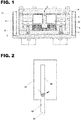
- the magnetron sputtering cathode assembly shown in FIG. 1 consists of a body in the form of a rectangular cuboid 1 with a base 2, an extended flat target 3 made of a sputtered material and fixed to the base 2, a magnetic system 4 and a cooler 5 in the form of coaxial toroids, located between the base of the body and the flat target in the centre of the body, wherein the central region of the flat target is perforated with slits 6 along its extended side, and wherein at the centre of the body an additional gas distribution system 7 is installed.
- the magnetic system is made in the form of a matrix of permanent plate-like magnets, which are uniform in magnetic properties and displaced towards each other in each row.
- the magnetic system is placed on a special support 8 with a height of at least 12 mm made of a ferromagnetic material.
- the Z-shaped heat-conducting shield 9 is made, for example, of copper and placed above the magnets 4. It is in thermal contact with the cooler 5 in the form of a rectangular tube and allows to protect the magnetic system from thermal radiation heating by the rear surface of the target.
- the casing 10 with cooled walls protects the body from thermal radiation heating by the vacuum chamber fitments.
- coaxial rotary feedthrough 11 for cooling, power supply and gas supply with a vacuum-sealed unit 12 allows for the target preheating and cleaning before the coating application to rotate the target surface of the unbalanced magnetron (UBM) apparatus 13 in the direction opposite to the coated workpieces, for example towards the chamber wall 14 in order to prevent contamination of the surface of the parts during that stage.
- UBM unbalanced magnetron
- the UBM is made in the form of a toroid compressed in the plane and consisting of a straight section 15 and curved sections 16, as shown in FIG. 3 .
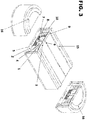
- the cathode's target has slits 6 for uniform supply of a working gas along the cathode through the gas distribution system 7.
- the middle section 17 of the cathode is made concave and complemented by the curved sections 16.
- the middle section 18 of the cathode is made convex and complemented by the curved sections 16.
- the inventive magnetron sputtering cathode assembly operates as follows.
- the device is placed in a vacuum chamber 14 from which air is evacuated, and then a plasma-forming gas is supplied through the coaxial feedthrough 11, the gas distribution system 7 and slits 6 in the target to the chamber.
- a coolant is supplied through the coaxial feedthrough cooling lines.
- the cathode assembly 13 is connected to the negative pole of the power supply, and the anode system (not shown) to the positive one.
- a gas-discharge plasma zone is created above the target, which is supported by crossed electric and magnetic fields. The electrons of the plasma formed above the target surface are confined by the magnetic field and move along a closed trajectory over the target surface, ionizing the plasma-forming gas.
- the resulting positive ions of the plasma-forming gas are accelerated by the electric field of the cathode assembly, gain kinetic energy and bombard the target so that the target material (titanium, aluminium, silicon, zirconium or other material) particles are knocked out from the target and condensed on the surface of the coated parts (not shown in the drawing).
- target material titanium, aluminium, silicon, zirconium or other material
- the magnetic system made of peripheral magnets with the required parameters forms an additional magnetic field in the form of a "bottle" with a strength of more than 100 Oe, which is sufficient to capture electrons with energy exceeding the ionization energy of the plasma-forming gas and the sputtered material.
- This provides the conditions for the DSSD existence and a possibility of both cleaning and preheating of the workpiece surface, as well as for ionic impact during coating stage, when a bias voltage is applied to the workpiece.
- the coolant circulating through the pipeline 5 provides cooling of the target 3, preventing its destruction by thermal loads, as well as cooling of the shield 9 of the magnets 4, protecting the magnets from thermal radiation from the target.
- the coolant circulating through the duct of the casing 10 prevents heating of the magnetron body walls from the thermal radiation of the vacuum chamber fitments and overheating of the outer side of the magnets.
- the front side of the UBM apparatus 13 is rotated in the direction opposite to the coated parts, for example, towards a chamber wall 14, thus preventing contamination of the surface of the parts during this stage.
- the UBM is rotated back towards the parts without loss of sealing. Thereafter, the coating can be applied.
Landscapes
- Chemical & Material Sciences (AREA)
- Engineering & Computer Science (AREA)
- Physics & Mathematics (AREA)
- Plasma & Fusion (AREA)
- Analytical Chemistry (AREA)
- Materials Engineering (AREA)
- Chemical Kinetics & Catalysis (AREA)
- Mechanical Engineering (AREA)
- Metallurgy (AREA)
- Organic Chemistry (AREA)
- Epidemiology (AREA)
- Public Health (AREA)
- Health & Medical Sciences (AREA)
- Physical Vapour Deposition (AREA)
Claims (7)
- Kathodenanordnung zum Magnetronsputtern, bestehend aus einem Körper, der die Form eines rechtwinkligen Quaders (1) aufweist und eine Basis (2) umfasst, aus einem verlängerten flachen Target (3), welches das zu sputternde Material enthält und an der Basis (2) des Körpers fixiert ist, sowie aus einem magnetischen System (4) und einem Kühler (5) in Form von koaxialen Toroiden, die zwischen der Basis (2) des Körpers und dem flachen Target (3) im Zentrum des Körpers angeordnet sind,
wobei der zentrale Bereich des flachen Targets (3) entlang seiner verlängerten Seite mit Löchern oder Schlitzen (6) perforiert ist, und
wobei die Kathodenanordnung zum Magnetronsputtern ferner ein zusätzliches Gasverteilungssystem (7) umfasst, welches im Zentrum des Körpers installiert ist,
dadurch gekennzeichnet, dass das magnetische System auf ferromagnetischen Trägern (8) an der Basis (2) montiert ist, und
dass die Kathodenanordnung zum Magnetronsputtern ferner einen Z-förmigen wärmeleitenden Schild (9) umfasst, der zwischen der inneren Oberfläche des Targets (3) und dem magnetischen System (4) installiert ist, wobei der Z-förmige wärmeleitende Schild (9) mit dem in Form eines rechtwinkligen Kanals ausgebildeten Kühler (5) verbunden ist, und ein Gehäuse (10) mit gekühlten Wänden,
wobei die Basis (2) mit einer koaxialen radialen Durchführung (11) versehen ist, die eine vakuumdichte Einheit (12) für Kühlung, Energieversorgung und Gasversorgungsleitungen aufweist. - Kathodenanordnung zum Magnetronsputtern nach Anspruch 1, wobei die ferromagnetischen Träger (8) eine Höhe von mindestens 12 mm aufweisen.
- Kathodenanordnung zum Magnetronsputtern nach Anspruch 1 oder 2, wobei das magnetische System (4) in einem Hohlraum angeordnet ist.
- Kathodenanordnung zum Magnetronsputtern nach einem der Ansprüche 1 bis 3, wobei das magnetische System (4) und der Kühler (5) in Form von symmetrisch deformierten Toroiden ausgeführt sind, die in ihren Mittelteilen (17) konkav sind, und wobei die Form des Targets (3) die Form des Kühlers (5) repliziert.
- Kathodenanordnung zum Magnetronsputtern nach einem der Ansprüche 1 bis 3, wobei das magnetische System (4) und der Kühler (5) in Form von symmetrisch deformierten Toroiden ausgeführt sind, die in ihren Mittelteilen (18) konvex sind, und wobei die Form des Targets (3) die Form des Kühlers (5) repliziert.
- Vorrichtung (13) zum unbalanzierten Magnetronsputtern, umfassend die Kathodenanordnung zum Magnetronsputtern nach einem der Ansprüche 1 bis 5.
- Verwendung der Vorrichtung zum unbalanzierten Magnetronsputtern nach Anspruch 6 zum Reinigen, Erhitzen oder Ätzen der Oberflächen von Produkten, oder für das Aufbringen von Beschichtungen.
Priority Applications (3)
| Application Number | Priority Date | Filing Date | Title |
|---|---|---|---|
| EP18214105.1A EP3671806B1 (de) | 2018-12-19 | 2018-12-19 | Magnetron-sputterkathodenanordnung für eine sputtervorrichtung mit ungleichmässigem magnetron |
| PL18214105T PL3671806T3 (pl) | 2018-12-19 | 2018-12-19 | Zespół katodowy do rozpylania magnetronowego dla urządzenia rozpylającego z niezrównoważonym magnetroem |
| ES18214105T ES2855155T3 (es) | 2018-12-19 | 2018-12-19 | Conjunto de cátodo de pulverización catódica con magnetrón para un aparato de pulverización catódica con magnetrón desequilibrado |
Applications Claiming Priority (1)
| Application Number | Priority Date | Filing Date | Title |
|---|---|---|---|
| EP18214105.1A EP3671806B1 (de) | 2018-12-19 | 2018-12-19 | Magnetron-sputterkathodenanordnung für eine sputtervorrichtung mit ungleichmässigem magnetron |
Publications (2)
| Publication Number | Publication Date |
|---|---|
| EP3671806A1 EP3671806A1 (de) | 2020-06-24 |
| EP3671806B1 true EP3671806B1 (de) | 2020-12-02 |
Family
ID=64755136
Family Applications (1)
| Application Number | Title | Priority Date | Filing Date |
|---|---|---|---|
| EP18214105.1A Active EP3671806B1 (de) | 2018-12-19 | 2018-12-19 | Magnetron-sputterkathodenanordnung für eine sputtervorrichtung mit ungleichmässigem magnetron |
Country Status (3)
| Country | Link |
|---|---|
| EP (1) | EP3671806B1 (de) |
| ES (1) | ES2855155T3 (de) |
| PL (1) | PL3671806T3 (de) |
Family Cites Families (5)
| Publication number | Priority date | Publication date | Assignee | Title |
|---|---|---|---|---|
| US4517070A (en) * | 1984-06-28 | 1985-05-14 | General Motors Corporation | Magnetron sputtering cathode assembly and magnet assembly therefor |
| RU11138U1 (ru) | 1998-05-05 | 1999-09-16 | Товарищество с ограниченной ответственностью "Ключ" | Изделие из спрессованных частиц |
| US7931787B2 (en) * | 2002-02-26 | 2011-04-26 | Donald Bennett Hilliard | Electron-assisted deposition process and apparatus |
| RU2319788C2 (ru) | 2006-02-28 | 2008-03-20 | Михаил Антонович Парфененок | Узел катода магнетронного распылителя |
| RU111138U1 (ru) | 2011-05-20 | 2011-12-10 | Михаил Антонович Парфененок | Катодно-распылительный узел магнетрона (варианты) |
-
2018
- 2018-12-19 PL PL18214105T patent/PL3671806T3/pl unknown
- 2018-12-19 ES ES18214105T patent/ES2855155T3/es active Active
- 2018-12-19 EP EP18214105.1A patent/EP3671806B1/de active Active
Also Published As
| Publication number | Publication date |
|---|---|
| EP3671806A1 (de) | 2020-06-24 |
| ES2855155T3 (es) | 2021-09-23 |
| PL3671806T3 (pl) | 2021-08-23 |
Similar Documents
| Publication | Publication Date | Title |
|---|---|---|
| KR100776861B1 (ko) | 큰 영역 기판의 마그네트론 스퍼터링 시스템 | |
| EP3347503B1 (de) | Vakuumverarbeitungsvorrichtung und verfahren zur vakuumverarbeitung von substraten | |
| US20070056850A1 (en) | Large-area magnetron sputtering chamber with individually controlled sputtering zones | |
| US20100276283A1 (en) | Vacuum coating unit for homogeneous PVD coating | |
| WO2011119611A2 (en) | Dielectric deposition using a remote plasma source | |
| US11784032B2 (en) | Tilted magnetron in a PVD sputtering deposition chamber | |
| WO2010044257A1 (ja) | スパッタリング装置、薄膜形成方法及び電界効果型トランジスタの製造方法 | |
| Kosari Mehr et al. | Magnetron sputtering issues concerning growth of magnetic films: a technical approach to background, solutions, and outlook | |
| CN114015997A (zh) | 一种离子辅助的多靶磁控溅射设备 | |
| IL223408A (en) | Irrigation Evolution Device with Height Speed for Layer Creation, Layer Creation Device and Layer Production Method for Coating Using the Irrigation Evaporator | |
| US11251024B2 (en) | Coating for chamber particle reduction | |
| JP2009280882A (ja) | スパッタ装置 | |
| KR20250110889A (ko) | 기판 상에 물질을 증착하기 위한 시스템 및 방법들 | |
| EP3671806B1 (de) | Magnetron-sputterkathodenanordnung für eine sputtervorrichtung mit ungleichmässigem magnetron | |
| RU2242821C2 (ru) | Магнетронная распылительная система | |
| Burcalova et al. | Ion energy distributions and efficiency of sputtering process in HIPIMS system | |
| US20120024229A1 (en) | Control of plasma profile using magnetic null arrangement by auxiliary magnets | |
| Aufderheide | Sputtered thin film coatings | |
| CN217052381U (zh) | 一种离子辅助的多靶磁控溅射设备 | |
| KR102284028B1 (ko) | 단일 산화물 금속 증착 챔버 | |
| Maiti et al. | An evaporation system for film deposition using electron beam sources | |
| CN101864559B (zh) | 一种栅网磁控溅射蒸铪的方法 | |
| US20080023319A1 (en) | Magnetron assembly | |
| CN107075664A (zh) | 高性价比的整体式旋转靶材 | |
| KR20190119274A (ko) | 스퍼터 건 및 이를 포함하는 스퍼터링 증착 장치 |
Legal Events
| Date | Code | Title | Description |
|---|---|---|---|
| PUAI | Public reference made under article 153(3) epc to a published international application that has entered the european phase |
Free format text: ORIGINAL CODE: 0009012 |
|
| STAA | Information on the status of an ep patent application or granted ep patent |
Free format text: STATUS: REQUEST FOR EXAMINATION WAS MADE |
|
| 17P | Request for examination filed |
Effective date: 20200130 |
|
| AK | Designated contracting states |
Kind code of ref document: A1 Designated state(s): AL AT BE BG CH CY CZ DE DK EE ES FI FR GB GR HR HU IE IS IT LI LT LU LV MC MK MT NL NO PL PT RO RS SE SI SK SM TR |
|
| AX | Request for extension of the european patent |
Extension state: BA ME |
|
| GRAP | Despatch of communication of intention to grant a patent |
Free format text: ORIGINAL CODE: EPIDOSNIGR1 |
|
| STAA | Information on the status of an ep patent application or granted ep patent |
Free format text: STATUS: GRANT OF PATENT IS INTENDED |
|
| INTG | Intention to grant announced |
Effective date: 20200716 |
|
| GRAS | Grant fee paid |
Free format text: ORIGINAL CODE: EPIDOSNIGR3 |
|
| GRAA | (expected) grant |
Free format text: ORIGINAL CODE: 0009210 |
|
| STAA | Information on the status of an ep patent application or granted ep patent |
Free format text: STATUS: THE PATENT HAS BEEN GRANTED |
|
| AK | Designated contracting states |
Kind code of ref document: B1 Designated state(s): AL AT BE BG CH CY CZ DE DK EE ES FI FR GB GR HR HU IE IS IT LI LT LU LV MC MK MT NL NO PL PT RO RS SE SI SK SM TR |
|
| REG | Reference to a national code |
Ref country code: GB Ref legal event code: FG4D |
|
| REG | Reference to a national code |
Ref country code: AT Ref legal event code: REF Ref document number: 1341838 Country of ref document: AT Kind code of ref document: T Effective date: 20201215 Ref country code: CH Ref legal event code: EP |
|
| REG | Reference to a national code |
Ref country code: IE Ref legal event code: FG4D |
|
| REG | Reference to a national code |
Ref country code: DE Ref legal event code: R096 Ref document number: 602018010394 Country of ref document: DE |
|
| REG | Reference to a national code |
Ref country code: CH Ref legal event code: NV Representative=s name: VALIPAT S.A. C/O BOVARD SA NEUCHATEL, CH |
|
| REG | Reference to a national code |
Ref country code: NL Ref legal event code: FP |
|
| PG25 | Lapsed in a contracting state [announced via postgrant information from national office to epo] |
Ref country code: GR Free format text: LAPSE BECAUSE OF FAILURE TO SUBMIT A TRANSLATION OF THE DESCRIPTION OR TO PAY THE FEE WITHIN THE PRESCRIBED TIME-LIMIT Effective date: 20210303 Ref country code: NO Free format text: LAPSE BECAUSE OF FAILURE TO SUBMIT A TRANSLATION OF THE DESCRIPTION OR TO PAY THE FEE WITHIN THE PRESCRIBED TIME-LIMIT Effective date: 20210302 Ref country code: RS Free format text: LAPSE BECAUSE OF FAILURE TO SUBMIT A TRANSLATION OF THE DESCRIPTION OR TO PAY THE FEE WITHIN THE PRESCRIBED TIME-LIMIT Effective date: 20201202 Ref country code: FI Free format text: LAPSE BECAUSE OF FAILURE TO SUBMIT A TRANSLATION OF THE DESCRIPTION OR TO PAY THE FEE WITHIN THE PRESCRIBED TIME-LIMIT Effective date: 20201202 |
|
| PG25 | Lapsed in a contracting state [announced via postgrant information from national office to epo] |
Ref country code: SE Free format text: LAPSE BECAUSE OF FAILURE TO SUBMIT A TRANSLATION OF THE DESCRIPTION OR TO PAY THE FEE WITHIN THE PRESCRIBED TIME-LIMIT Effective date: 20201202 Ref country code: LV Free format text: LAPSE BECAUSE OF FAILURE TO SUBMIT A TRANSLATION OF THE DESCRIPTION OR TO PAY THE FEE WITHIN THE PRESCRIBED TIME-LIMIT Effective date: 20201202 |
|
| PG25 | Lapsed in a contracting state [announced via postgrant information from national office to epo] |
Ref country code: HR Free format text: LAPSE BECAUSE OF FAILURE TO SUBMIT A TRANSLATION OF THE DESCRIPTION OR TO PAY THE FEE WITHIN THE PRESCRIBED TIME-LIMIT Effective date: 20201202 |
|
| REG | Reference to a national code |
Ref country code: LT Ref legal event code: MG9D |
|
| PG25 | Lapsed in a contracting state [announced via postgrant information from national office to epo] |
Ref country code: SK Free format text: LAPSE BECAUSE OF FAILURE TO SUBMIT A TRANSLATION OF THE DESCRIPTION OR TO PAY THE FEE WITHIN THE PRESCRIBED TIME-LIMIT Effective date: 20201202 Ref country code: SM Free format text: LAPSE BECAUSE OF FAILURE TO SUBMIT A TRANSLATION OF THE DESCRIPTION OR TO PAY THE FEE WITHIN THE PRESCRIBED TIME-LIMIT Effective date: 20201202 Ref country code: CZ Free format text: LAPSE BECAUSE OF FAILURE TO SUBMIT A TRANSLATION OF THE DESCRIPTION OR TO PAY THE FEE WITHIN THE PRESCRIBED TIME-LIMIT Effective date: 20201202 Ref country code: EE Free format text: LAPSE BECAUSE OF FAILURE TO SUBMIT A TRANSLATION OF THE DESCRIPTION OR TO PAY THE FEE WITHIN THE PRESCRIBED TIME-LIMIT Effective date: 20201202 Ref country code: LT Free format text: LAPSE BECAUSE OF FAILURE TO SUBMIT A TRANSLATION OF THE DESCRIPTION OR TO PAY THE FEE WITHIN THE PRESCRIBED TIME-LIMIT Effective date: 20201202 Ref country code: RO Free format text: LAPSE BECAUSE OF FAILURE TO SUBMIT A TRANSLATION OF THE DESCRIPTION OR TO PAY THE FEE WITHIN THE PRESCRIBED TIME-LIMIT Effective date: 20201202 Ref country code: PT Free format text: LAPSE BECAUSE OF FAILURE TO SUBMIT A TRANSLATION OF THE DESCRIPTION OR TO PAY THE FEE WITHIN THE PRESCRIBED TIME-LIMIT Effective date: 20210405 |
|
| REG | Reference to a national code |
Ref country code: DE Ref legal event code: R097 Ref document number: 602018010394 Country of ref document: DE |
|
| REG | Reference to a national code |
Ref country code: ES Ref legal event code: FG2A Ref document number: 2855155 Country of ref document: ES Kind code of ref document: T3 Effective date: 20210923 |
|
| PG25 | Lapsed in a contracting state [announced via postgrant information from national office to epo] |
Ref country code: IS Free format text: LAPSE BECAUSE OF FAILURE TO SUBMIT A TRANSLATION OF THE DESCRIPTION OR TO PAY THE FEE WITHIN THE PRESCRIBED TIME-LIMIT Effective date: 20210402 Ref country code: MC Free format text: LAPSE BECAUSE OF FAILURE TO SUBMIT A TRANSLATION OF THE DESCRIPTION OR TO PAY THE FEE WITHIN THE PRESCRIBED TIME-LIMIT Effective date: 20201202 |
|
| PLBE | No opposition filed within time limit |
Free format text: ORIGINAL CODE: 0009261 |
|
| STAA | Information on the status of an ep patent application or granted ep patent |
Free format text: STATUS: NO OPPOSITION FILED WITHIN TIME LIMIT |
|
| PG25 | Lapsed in a contracting state [announced via postgrant information from national office to epo] |
Ref country code: AL Free format text: LAPSE BECAUSE OF FAILURE TO SUBMIT A TRANSLATION OF THE DESCRIPTION OR TO PAY THE FEE WITHIN THE PRESCRIBED TIME-LIMIT Effective date: 20201202 Ref country code: LU Free format text: LAPSE BECAUSE OF NON-PAYMENT OF DUE FEES Effective date: 20201219 Ref country code: IE Free format text: LAPSE BECAUSE OF NON-PAYMENT OF DUE FEES Effective date: 20201219 |
|
| 26N | No opposition filed |
Effective date: 20210903 |
|
| PG25 | Lapsed in a contracting state [announced via postgrant information from national office to epo] |
Ref country code: SI Free format text: LAPSE BECAUSE OF FAILURE TO SUBMIT A TRANSLATION OF THE DESCRIPTION OR TO PAY THE FEE WITHIN THE PRESCRIBED TIME-LIMIT Effective date: 20201202 Ref country code: DK Free format text: LAPSE BECAUSE OF FAILURE TO SUBMIT A TRANSLATION OF THE DESCRIPTION OR TO PAY THE FEE WITHIN THE PRESCRIBED TIME-LIMIT Effective date: 20201202 |
|
| PG25 | Lapsed in a contracting state [announced via postgrant information from national office to epo] |
Ref country code: IS Free format text: LAPSE BECAUSE OF FAILURE TO SUBMIT A TRANSLATION OF THE DESCRIPTION OR TO PAY THE FEE WITHIN THE PRESCRIBED TIME-LIMIT Effective date: 20210402 Ref country code: TR Free format text: LAPSE BECAUSE OF FAILURE TO SUBMIT A TRANSLATION OF THE DESCRIPTION OR TO PAY THE FEE WITHIN THE PRESCRIBED TIME-LIMIT Effective date: 20201202 Ref country code: MT Free format text: LAPSE BECAUSE OF FAILURE TO SUBMIT A TRANSLATION OF THE DESCRIPTION OR TO PAY THE FEE WITHIN THE PRESCRIBED TIME-LIMIT Effective date: 20201202 Ref country code: CY Free format text: LAPSE BECAUSE OF FAILURE TO SUBMIT A TRANSLATION OF THE DESCRIPTION OR TO PAY THE FEE WITHIN THE PRESCRIBED TIME-LIMIT Effective date: 20201202 |
|
| PG25 | Lapsed in a contracting state [announced via postgrant information from national office to epo] |
Ref country code: MK Free format text: LAPSE BECAUSE OF FAILURE TO SUBMIT A TRANSLATION OF THE DESCRIPTION OR TO PAY THE FEE WITHIN THE PRESCRIBED TIME-LIMIT Effective date: 20201202 |
|
| P01 | Opt-out of the competence of the unified patent court (upc) registered |
Effective date: 20230519 |
|
| REG | Reference to a national code |
Ref country code: AT Ref legal event code: UEP Ref document number: 1341838 Country of ref document: AT Kind code of ref document: T Effective date: 20201202 |
|
| REG | Reference to a national code |
Ref country code: CH Ref legal event code: U11 Free format text: ST27 STATUS EVENT CODE: U-0-0-U10-U11 (AS PROVIDED BY THE NATIONAL OFFICE) Effective date: 20260101 |
|
| PGFP | Annual fee paid to national office [announced via postgrant information from national office to epo] |
Ref country code: GB Payment date: 20251211 Year of fee payment: 8 |
|
| PGFP | Annual fee paid to national office [announced via postgrant information from national office to epo] |
Ref country code: AT Payment date: 20251209 Year of fee payment: 8 |
|
| PGFP | Annual fee paid to national office [announced via postgrant information from national office to epo] |
Ref country code: IT Payment date: 20251219 Year of fee payment: 8 |
|
| PGFP | Annual fee paid to national office [announced via postgrant information from national office to epo] |
Ref country code: NL Payment date: 20251215 Year of fee payment: 8 Ref country code: FR Payment date: 20251208 Year of fee payment: 8 |
|
| PGFP | Annual fee paid to national office [announced via postgrant information from national office to epo] |
Ref country code: BE Payment date: 20251231 Year of fee payment: 8 |
|
| PGFP | Annual fee paid to national office [announced via postgrant information from national office to epo] |
Ref country code: BG Payment date: 20251215 Year of fee payment: 8 Ref country code: PL Payment date: 20251128 Year of fee payment: 8 |
|
| PGFP | Annual fee paid to national office [announced via postgrant information from national office to epo] |
Ref country code: ES Payment date: 20260114 Year of fee payment: 8 |
|
| PGFP | Annual fee paid to national office [announced via postgrant information from national office to epo] |
Ref country code: DE Payment date: 20251217 Year of fee payment: 8 |
|
| PGFP | Annual fee paid to national office [announced via postgrant information from national office to epo] |
Ref country code: CH Payment date: 20260101 Year of fee payment: 8 |