EP3671660A1 - Conception d'un objet modélisé 3d par l'intermédiaire d'une interaction de l'utilisateur - Google Patents
Conception d'un objet modélisé 3d par l'intermédiaire d'une interaction de l'utilisateur Download PDFInfo
- Publication number
- EP3671660A1 EP3671660A1 EP18306758.6A EP18306758A EP3671660A1 EP 3671660 A1 EP3671660 A1 EP 3671660A1 EP 18306758 A EP18306758 A EP 18306758A EP 3671660 A1 EP3671660 A1 EP 3671660A1
- Authority
- EP
- European Patent Office
- Prior art keywords
- modeled object
- decoder
- applying
- latent vector
- latent
- Prior art date
- Legal status (The legal status is an assumption and is not a legal conclusion. Google has not performed a legal analysis and makes no representation as to the accuracy of the status listed.)
- Pending
Links
Images


Classifications
-
- G—PHYSICS
- G06—COMPUTING; CALCULATING OR COUNTING
- G06T—IMAGE DATA PROCESSING OR GENERATION, IN GENERAL
- G06T19/00—Manipulating 3D models or images for computer graphics
- G06T19/20—Editing of 3D images, e.g. changing shapes or colours, aligning objects or positioning parts
-
- G—PHYSICS
- G06—COMPUTING; CALCULATING OR COUNTING
- G06F—ELECTRIC DIGITAL DATA PROCESSING
- G06F30/00—Computer-aided design [CAD]
- G06F30/10—Geometric CAD
- G06F30/12—Geometric CAD characterised by design entry means specially adapted for CAD, e.g. graphical user interfaces [GUI] specially adapted for CAD
-
- G—PHYSICS
- G06—COMPUTING; CALCULATING OR COUNTING
- G06T—IMAGE DATA PROCESSING OR GENERATION, IN GENERAL
- G06T17/00—Three dimensional [3D] modelling, e.g. data description of 3D objects
-
- G—PHYSICS
- G06—COMPUTING; CALCULATING OR COUNTING
- G06F—ELECTRIC DIGITAL DATA PROCESSING
- G06F30/00—Computer-aided design [CAD]
- G06F30/20—Design optimisation, verification or simulation
- G06F30/27—Design optimisation, verification or simulation using machine learning, e.g. artificial intelligence, neural networks, support vector machines [SVM] or training a model
-
- G—PHYSICS
- G06—COMPUTING; CALCULATING OR COUNTING
- G06T—IMAGE DATA PROCESSING OR GENERATION, IN GENERAL
- G06T9/00—Image coding
- G06T9/001—Model-based coding, e.g. wire frame
-
- G—PHYSICS
- G06—COMPUTING; CALCULATING OR COUNTING
- G06T—IMAGE DATA PROCESSING OR GENERATION, IN GENERAL
- G06T9/00—Image coding
- G06T9/002—Image coding using neural networks
-
- G—PHYSICS
- G06—COMPUTING; CALCULATING OR COUNTING
- G06F—ELECTRIC DIGITAL DATA PROCESSING
- G06F2111/00—Details relating to CAD techniques
- G06F2111/10—Numerical modelling
-
- G—PHYSICS
- G06—COMPUTING; CALCULATING OR COUNTING
- G06N—COMPUTING ARRANGEMENTS BASED ON SPECIFIC COMPUTATIONAL MODELS
- G06N3/00—Computing arrangements based on biological models
- G06N3/02—Neural networks
- G06N3/04—Architecture, e.g. interconnection topology
- G06N3/045—Combinations of networks
-
- G—PHYSICS
- G06—COMPUTING; CALCULATING OR COUNTING
- G06N—COMPUTING ARRANGEMENTS BASED ON SPECIFIC COMPUTATIONAL MODELS
- G06N3/00—Computing arrangements based on biological models
- G06N3/02—Neural networks
- G06N3/08—Learning methods
- G06N3/088—Non-supervised learning, e.g. competitive learning
-
- G—PHYSICS
- G06—COMPUTING; CALCULATING OR COUNTING
- G06T—IMAGE DATA PROCESSING OR GENERATION, IN GENERAL
- G06T2200/00—Indexing scheme for image data processing or generation, in general
- G06T2200/04—Indexing scheme for image data processing or generation, in general involving 3D image data
-
- G—PHYSICS
- G06—COMPUTING; CALCULATING OR COUNTING
- G06T—IMAGE DATA PROCESSING OR GENERATION, IN GENERAL
- G06T2200/00—Indexing scheme for image data processing or generation, in general
- G06T2200/24—Indexing scheme for image data processing or generation, in general involving graphical user interfaces [GUIs]
-
- G—PHYSICS
- G06—COMPUTING; CALCULATING OR COUNTING
- G06T—IMAGE DATA PROCESSING OR GENERATION, IN GENERAL
- G06T2219/00—Indexing scheme for manipulating 3D models or images for computer graphics
- G06T2219/20—Indexing scheme for editing of 3D models
- G06T2219/2021—Shape modification
Definitions
- the invention relates to the field of computer programs and systems, and more specifically to a method, system and program for designing a 3D modeled object via user-interaction.
- CAD Computer-Aided Design
- CAE Computer-Aided Engineering
- CAM Computer-Aided Manufacturing
- the graphical user interface plays an important role as regards the efficiency of the technique.
- PLM refers to a business strategy that helps companies to share product data, apply common processes, and leverage corporate knowledge for the development of products from conception to the end of their life, across the concept of extended enterprise.
- the PLM solutions provided by Dassault Systèmes (under the trademarks CATIA, ENOVIA and DELMIA) provide an Engineering Hub, which organizes product engineering knowledge, a Manufacturing Hub, which manages manufacturing engineering knowledge, and an Enterprise Hub which enables enterprise integrations and connections into both the Engineering and Manufacturing Hubs. All together the system delivers an open object model linking products, processes, resources to enable dynamic, knowledge-based product creation and decision support that drives optimized product definition, manufacturing preparation, production and service.
- autoencoders Given a dataset representing samples from a same class, for example a dataset of images of chairs, or a dataset of 3D models of cars, autoencoders (explained in [1,2]) aims at learning a mapping between the original input space of this dataset and a low-dimensional space, often called latent space. Moreover, autoencoders also learn a reverse mapping from the latent space to the original input space. They may be used to do realistic non-linear interpolation in the original spaces, extract meaningful features in the data, compress the data into a compact representation, etc.
- Paper [4] introduces a generative adversarial network, a model which learns a decoder, but also sets a probabilistic prior on the latent space to learn the distribution of the data. To do so, they train the decoder in order to fool a discriminator, whereas the discriminator is trained to classify between real data and synthetized data. One can also learn an encoder to project the data onto the latent space, using a reconstruction error like autoencoders.
- Paper [5] learns a generative adversarial network on images. The modifications are finally retargeted onto the original image with optical flow.
- Paper [6] also proposes an edition system onto images, by learning an introspective adversarial network, an hybridization between a variational autoencoder and a generative adversarial network, but they retarget the user modifications with masking techniques instead of optical flow.
- the method comprises providing the 3D modeled object and a machine-learnt decoder.
- the machine-learnt decoder is a differentiable function taking values in a latent space and outputting values in a 3D modeled object space.
- the method further comprises defining, by a user, a deformation constraint for a part of the 3D modeled object.
- the method further comprises determining an optimal vector.
- the optimal vector minimizes an energy.
- the energy explores latent vectors.
- the energy comprises a term which penalizes, for each explored latent vector, non-respect of the deformation constraint by the result of applying the decoder to the explored latent vector.
- the method further comprises applying the decoder to the optimal latent vector.
- Such a method constitutes an improved method for designing a 3D modeled object via user-interaction.
- the method makes use of a machine-learnt decoder in the context of designing a 3D modeled object via user-interaction.
- the user defines a deformation constraint for a part of the 3D modeled object.
- the user provides a design intent of which purpose is to deform the 3D modeled object.
- the method determines the optimal latent vector, which is a vector minimizing an energy that penalizes non-respect of the deformation constraint on the latent vector space.
- the determined optimal latent vector is a vector of the latent space tending to respect the deformation constraint.
- the optimal latent vector respects ( e.g. optimally) the deformation constraint.
- the optimal latent vector is then decoded into an element of the 3D modeled object space.
- the method finds a 3D modeled object which tends to respect ( e.g. respects, e.g. optimally) the deformation constraint provided by the user.
- the method allows to find a 3D modeled object which tends to respect ( e.g. respects) the user's design intent.
- the determining of the optimal latent vector and the applying of the decoder to the optimal latent vector may be carried out automatically, thus without involving user actions, as a result of the providing of the deformation constraint by the user.
- the method output a 3D modeled object tending to respect the user's design intent, but the method does so with few user-machine interactions. The method is thus efficient and ergonomic.
- the decoder may output only plausible 3D modeled objects because the decoder may have been machine-learnt to do so.
- the 3D modeled object space may be a space of plausible 3D modeled objects.
- the method may output a plausible 3D modeled object tending to respect the user's design intent in an ergonomic and efficient way.
- the method may comprise one or more of the following:
- a system comprising a processor coupled to a memory and a graphical user interface, the memory having recorded thereon the computer program.
- the method comprises providing S10 the 3D modeled object and a machine-learnt decoder.
- the machine-learnt decoder is a differentiable function taking values in a latent space and outputting values in a 3D modeled object space.
- the method further comprises defining S30, by a user, a deformation constraint for a part of the 3D modeled object.
- the method further comprises determining S40 an optimal vector.
- the optimal vector minimizes an energy.
- the energy explores latent vectors.
- the energy comprises a term which penalizes, for each explored latent vector, non-respect of the deformation constraint by the result of applying the decoder to the explored latent vector.
- the method further comprises applying S50 the decoder to the optimal latent vector.
- the method is computer-implemented. This means that steps (or substantially all the steps) of the method are executed by at least one computer, or any system alike. Thus, steps of the method are performed by the computer, possibly fully automatically, or, semi-automatically. In examples, the triggering of at least some of the steps of the method may be performed through user-computer interaction.
- the level of user-computer interaction required may depend on the level of automatism foreseen and put in balance with the need to implement user's wishes. In examples, this level may be user-defined and/or pre-defined.
- a typical example of computer-implementation of a method is to perform the method with a system adapted for this purpose.
- the system may comprise a processor coupled to a memory and a graphical user interface (GUI), the memory having recorded thereon a computer program comprising instructions for performing the method.
- GUI graphical user interface
- the memory may also store a database.
- the memory is any hardware adapted for such storage, possibly comprising several physical distinct parts (e.g. one for the program, and possibly one for the database).
- the method generally manipulates modeled objects.
- a modeled object is any object defined by data stored e.g. in the database.
- the expression "modeled object" designates the data itself.
- the modeled objects may be defined by different kinds of data.
- the system may indeed be any combination of a CAD system, a CAE system, a CAM system, a PDM system and/or a PLM system.
- modeled objects are defined by corresponding data.
- One may accordingly speak of CAD object, PLM object, PDM object, CAE object, CAM object, CAD data, PLM data, PDM data, CAM data, CAE data.
- these systems are not exclusive one of the other, as a modeled object may be defined by data corresponding to any combination of these systems.
- a system may thus well be both a CAD and PLM system, as will be apparent from the definitions of such systems provided below.
- CAD system it is additionally meant any system adapted at least for designing a modeled object on the basis of a graphical representation of the modeled object, such as CATIA.
- the data defining a modeled object comprise data allowing the representation of the modeled object.
- a CAD system may for example provide a representation of CAD modeled objects using edges or lines, in certain cases with faces or surfaces. Lines, edges, or surfaces may be represented in various manners, e.g. non-uniform rational B-splines (NURBS).
- NURBS non-uniform rational B-splines
- a CAD file contains specifications, from which geometry may be generated, which in turn allows for a representation to be generated. Specifications of a modeled object may be stored in a single CAD file or multiple ones.
- the typical size of a file representing a modeled object in a CAD system is in the range of one Megabyte per part.
- a modeled object may typically be an assembly of thousands of parts.
- a modeled object may typically be a 3D modeled object, e.g. representing a product such as a part or an assembly of parts, or possibly an assembly of products.
- 3D modeled object it is meant any object which is modeled by data allowing its 3D representation.
- a 3D representation allows the viewing of the part from all angles.
- a 3D modeled object when 3D represented, may be handled and turned around any of its axes, or around any axis in the screen on which the representation is displayed. This notably excludes 2D icons, which are not 3D modeled.
- the display of a 3D representation facilitates design (i.e. increases the speed at which designers statistically accomplish their task). This speeds up the manufacturing process in the industry, as the design of the products is part of the manufacturing process.
- the 3D modeled object may represent the geometry of a product to be manufactured in the real world subsequent to the completion of its virtual design with for example a CAD software solution or CAD system, such as a (e.g. mechanical) part or assembly of parts (or equivalently an assembly of parts, as the assembly of parts may be seen as a part itself from the point of view of the method, or the method may be applied independently to each part of the assembly), or more generally any rigid body assembly (e.g. a mobile mechanism).
- a CAD software solution allows the design of products in various and unlimited industrial fields, including: aerospace, architecture, construction, consumer goods, high-tech devices, industrial equipment, transportation, marine, and/or offshore oil/gas production or transportation.
- the 3D modeled object designed by the method may thus represent an industrial product which may be any mechanical part, such as a part of a terrestrial vehicle (including e.g. car and light truck equipment, racing cars, motorcycles, truck and motor equipment, trucks and buses, trains), a part of an aerial vehicle (including e.g. airframe equipment, aerospace equipment, propulsion equipment, defense products, airline equipment, space equipment), a part of a naval vehicle (including e.g. navy equipment, commercial ships, offshore equipment, yachts and workboats, marine equipment), a general mechanical part (including e.g. industrial manufacturing machinery, heavy mobile machinery or equipment, installed equipment, industrial equipment product, fabricated metal product, tire manufacturing product), an electro-mechanical or electronic part (including e.g.
- a terrestrial vehicle including e.g. car and light truck equipment, racing cars, motorcycles, truck and motor equipment, trucks and buses, trains
- an aerial vehicle including e.g. airframe equipment, aerospace equipment, propulsion equipment, defense products, airline equipment, space equipment
- a consumer good including e.g. furniture, home and garden products, leisure goods, fashion products, hard goods retailers' products, soft goods retailers' products
- a packaging including e.g. food and beverage and tobacco, beauty and personal care, household product packaging.
- any 3D modeled object designed by the method and/or involved in the method may represent a mechanical part which is one or a plausible combination of a molded part ( i.e. a part manufactured by a molding manufacturing process), a machined part ( i.e. a part manufactured by a machining manufacturing process), a drilled part ( i.e. a part manufactured by a drilling manufacturing process), a turned part ( i.e. a part manufactured by a turning manufacturing process), a forged part ( i.e. a part manufactured by a forging manufacturing process), a stamped part ( i.e. a part manufactured by a stamping manufacturing process) and/or a folded part ( i.e. a part manufactured by a folding manufacturing process).
- a molded part i.e. a part manufactured by a molding manufacturing process
- a machined part i.e. a part manufactured by a machining manufacturing process
- a drilled part i.e. a part manufactured by a drilling
- Any 3D modeled object designed by the method and/or involved in the method may be a plausible ( e.g. realistic) 3D modeled object.
- a plausible 3D modeled object may designate a 3D modeled object representing a plausible ( e.g. realistic) mechanical part.
- a plausible mechanical part may designate a mechanical part realistically manufacturable in a real-world industrial manufacturing process.
- a plausible mechanical part may refer to a mechanical part which respects all the constraints that must be respected in order to realistically manufacture the mechanical part in a real-world industrial manufacturing process.
- the constraints may comprise one or any plausible combination of the following: mechanical constraints (e.g. constraints resulting from the laws of classic mechanics), functional constraints (e.g.
- constraints relative to one or more mechanical functions to be performed by the mechanical part once manufactured include manufacturing constraints (e.g. constraints pertaining to the ability of applying one or more manufacturing tools to the mechanical part during one or more manufacturing processes for manufacturing the mechanical part), structural constraints (e.g. constraints pertaining to the strength and/or resistance of the mechanical part) and/or assembly constraints (e.g. constraints defining how the mechanical part can be assembled with one or more other mechanical parts).
- Designing a 3D modeled object designates any action or series of actions which is at least part of a process of elaborating a 3D modeled object.
- the method may comprise creating the 3D modeled object from scratch.
- the method may comprise providing a 3D modeled object previously created, and then modifying the 3D modeled object.
- the method may be included in a manufacturing process, which may comprise, after performing the method, producing a physical product corresponding to the modeled object.
- the modeled object designed by the method may represent a manufacturing object.
- the modeled object may thus be a modeled solid (i.e. a modeled object that represents a solid).
- the manufacturing object may be a product, such as a part, or an assembly of parts. Because the method improves the design of the modeled object, the method also improves the manufacturing of a product and thus increases productivity of the manufacturing process.
- the providing of the 3D modeled object may comprise displaying the 3D modeled object on a display of a computer such as a CAD system.
- the providing of the 3D modeled object may result from an action of a user, e.g. an interaction between the user and the computer.
- the 3D modeled object may have been designed by a another user on another computer and optionally stored in a memory and/or sent ( e.g. through a network) to the computer.
- the providing of the 3D modeled object may comprise retrieving the 3D modeled object from a memory.
- the user and the another user are different, and the computer and the another computer are different.
- the computer and the another computer may be connected by a network.
- the user and the another user are the same, and the computer and the another computer are the same.
- the 3D modeled object may be provided S10 as a mesh or as a point cloud.
- the providing S10 may comprise providing the 3D modeled object in any format ( e.g. as a CAD file) and meshing the 3D modeled object and/or determining ( e.g. inferring, e.g. extracting, e.g. computing), from the ( e.g. meshed) 3D modeled object, a point cloud representing the 3D modeled object.
- the machine-learnt decoder is a differentiable function.
- the function is machine-learnt.
- the function takes is values in a latent space.
- the latent space is a vector space.
- the function outputs values in a 3D modeled object space, i.e. a space comprising ( e.g. made of) 3D modeled objects.
- applying the function to vectors of the latent space (hereinafter referred to as "latent vectors") outputs 3D modeled objects.
- the image of each latent vector by the function is a 3D modeled object of the 3D modeled object space.
- the image of the latent space by the function may be the 3D modeled object space or a strict subset of the 3D modeled object space.
- Decoding a latent vector means applying the decoder to the latent vector.
- the result of the decoding may thus be referred to as "the decoded latent vector".
- the latent space features a probabilistic prior.
- a probabilistic prior which may be denoted p ( z ) in the following, may be given over the latent space, z being a notation for a vector of the latent space.
- the prior may be an a priori probability distribution expressing how the latent vectors are distributed over the latent space.
- a priori means that the probability distribution may be determined ( e.g. computed, e.g. established) without having complete knowledge of the latent space.
- the prior over the latent space may be inferred ( e.g. deduced) from an existing ( e.g. probability) distribution of the 3D modeled objects over the 3D modeled object space, such that the prior expresses a distribution of the latent vectors over the latent space that ( e.g. substantially) corresponds to the distribution of the 3D modeled objects over the 3D modeled object space.
- the machine-learnt decoder may be the decoder of an autoencoder.
- an autoencoder may be defined as the composition of two feedforward deep neural networks (see [3]) f w : R m ⁇ R p and g w ⁇ : R p ⁇ R m , parameterized by the weights w and w', where p ⁇ m .
- f w is the encoder
- g w' the decoder. is the latent space, i.e. the vector space where the encoder f w outputs its values and where the decoder g w' takes its values.
- p is the dimension of the latent space.
- the original input space is the space where the encoder f w takes its values and where the decoder g w' outputs its values. may be referred to as "the original input space".
- m is the dimension of the original input space.
- the original input space may be the 3D modeled object space.
- the 3D modeled object space may be a subset of the original input space.
- the encoder f w ( x ) takes its values in the original input space, but the image of the latent space by the decoder g w' , i.e. the 3D modeled object space in the context of the method, may be a subset of the original input space.
- the autoencoder g w' ⁇ f w ( x ) may also be referred to as "a reconstruction".
- the reconstruction takes as input a first element of the original input space (for example, a first 3D modeled object of the 3D modeled object space), maps it onto a latent vector of the latent vector space, and then reverse the mapping by outputting a second element of the original input space (for example, a second 3D modeled object of the 3D modeled object space) from the latent vector.
- the second element may be referred to as "a reconstruction" of the first element.
- the second element represents an approximation of the first element.
- the 3D modeled object g w' ⁇ f w ( x ) may be referred to as the reconstructed 3D modeled object.
- x may also be referred to as the input and g w' ⁇ f w ( x ) as the reconstructed input..
- the encoder f w , and the decoder g w may be machined-learnt (e.g. separately or simultaneously), e.g. by minimizing a reconstruction error.
- Encoding an object means applying the encoder to the object. The result of the encoding may thus be referred to as "the encoded object”.
- Decoding a latent vector means applying the decoder to the latent vector. The result of the decoding may thus be referred to as "the decoded latent vector”.
- the providing S10 of the machine-learnt decoder may comprise retrieving the machine-learnt decoder from a database.
- the machine-learnt decoder may have been previously learnt and stored in a database for later use.
- the providing S10 of the machine-learnt decoder may be carried out by a user which accesses the decoder in a database. Additionally or alternatively, the providing S10 may comprise learning the decoder from scratch and making it available for use by the method.
- the 3D modeled object space generally refers to a space made of 3D modeled objects.
- the 3D modeled object space may be included in a vector space.
- the 3D modeled object space is a manifold, for example a connected manifold, of a vector space.
- the 3D modeled object space is made of 3D modeled objects of a same class of 3D modeled objects.
- a class of 3D modeled objects may correspond to a connected manifold of a vector space.
- a class of 3D modeled objects may designate a set of 3D modeled objects which has a the following property: any first 3D modeled object of the set is similar to, e.g. has a shape similar to, at least a second 3D modeled object of the set.
- the class of 3D modeled object is made of 3D modeled object representing respective mechanical parts, the mechanical parts relative (i.e. corresponding) to the class all respecting any one or any combination of the following conditions:
- the provided 3D modeled object and ( e.g. substantially) all the 3D modeled objects of the 3D modeled object space are 3D modeled objects of a same class of 3D modeled objects.
- the decoder may have been machine-learnt based on a dataset of 3D modeled objects of said same class.
- the decoder may have been machine-learnt to map any latent vector onto a 3D modeled object of said same class.
- the decoder may be the decoder of an autoencoder that further comprises an encoder, the decoder and the encoder having both being machine-learnt based on a dataset of 3D modeled objects of said same class.
- the encoder may have been machine-learnt to map any 3D object of said same class onto a latent vector of the latent space.
- the decoder may have been machine-learnt to map any latent vector onto a 3D modeled object of said same class.
- all modeled object of the 3D modeled object space are plausible 3D modeled objects.
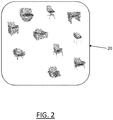
- FIG. 2 shows a class of 3D modeled objects forming an example of the set 20 of 3D modeled object of the method.
- the 3D modeled objects are chairs.
- the chairs form a class of 3D modeled object because they all perform the same mechanical function, which is supporting a weight ( e.g. of a human being). Performing this mechanical function also means that the chairs all obey to same mechanical constraints, functional constraints and structural constraints.
- the chairs of FIG. 2 are plausible mechanical parts, because they respect mechanical constraints, functional constraints, manufacturing constraints and structural constraints, thereby allowing their manufacturing in the real-world by one or more manufacturing process.
- FIG. 3 shows a class of 3D modeled objects forming an example of the set 30 of 3D modeled object of the method.
- the 3D modeled objects are chairs with four legs (each).
- the chairs with four legs form a class of 3D modeled object because they all perform the same mechanical function, which is supporting a weight ( e.g. of a human being), and because performing this mechanical function with four legs also means that the chairs all obey to same mechanical constraints, functional constraints and structural constraints.
- the chairs of FIG. 3 are plausible mechanical parts, because they respect mechanical constraints, functional constraints, manufacturing constraints and structural constraints, thereby allowing their manufacturing in the real-world by one or more manufacturing process.
- the 3D modeled object space may be a space made of discrete representations of 3D modeled objects, such as meshes and/or point clouds.
- the 3D modeled object space is made of respective discrete representations (such as meshes and/or point clouds) of 3D modeled objects of the space.
- the elements of the 3D modeled object space may still be referred to as the 3D modeled objects themselves, and not their respective discrete representations, for the sake of simplicity.
- the method comprises projecting S20 the 3D modeled object onto the latent space.
- the machine-learnt decoder may be the decoder of a machine-learnt autoencoder also comprising a machine-learnt encoder.
- Projecting S20 the 3D modeled object may consist in applying the encoder to the 3D modeled object, the applying of the encoder to the 3D modeled object resulting in a latent vector.
- the latent vector may be called the projection of the 3D modeled object on the latent space.
- the providing S10 of the 3D modeled object may comprise providing, besides the 3D modeled object, the latent vector which is the result of applying the encoder to the 3D modeled object.
- the projecting S20 may result in that a latent vector which is the projection of the 3D modeled object onto the latent space is made available for further use in the method, as discussed herein after.
- any 3D modeled objects designed by the method or involved in the method may be divided into parts.
- a part of the 3D modeled object may designate a layout of material of the mechanical part, the layout of material performing a mechanical function.
- the 3D modeled object representing the mechanical part may be divided into parts each representing a respective layout of material of the mechanical parts, the respective layout of material performing a respective mechanical function.
- a function performed by a layout of material of a mechanical part may be one or a plausible combination of a supporting function, a strengthening function, a resistance function, a connecting function between other layouts of material, a mass reduction function, a space reservation function, a fixture function, a tightness function, an adjustment function, a positioning function, a mechanical joint function, a cooling function, a space reservation function, a revolute or cylindrical mechanical joint function, an assembly function, a stiffening function, a positioning pin function, a revolute or cylindrical mechanical joint function and/or a support for all machined and drilled protrusions function.
- a leg of a chair such as a leg of any one of the chairs represented in FIG. 2 or FIG. 3
- the leg of the chair is involved ( e.g. as well as other legs) in performing the function of supporting the weight of further material forming the chair as well as the weight of a human sitting on the chair.
- FIG. 2 Another example is a ( e.g. bent) chair back, such as a chair back of any one of the chairs represented in FIG. 2 or FIG. 3 .
- the chair back is a layout of material of the chair performing a supporting function. In other words, the chair back is involved in performing the function of supporting the back of a human sitting on the chair.
- a chair seat such as a chair seat of any one of the chairs represented in FIG. 2 or FIG. 3 .
- the chair seat is a layout of material of the chair performing a supporting function.
- the chair seat is involved in performing the function of supporting the weight of further material forming the chair as well as the weight of a human sitting on the chair.
- the chair seat also performs a connecting function, since it connects other parts of the chair such as the chair back and/or the chair legs.
- Any 3D modeled object involved in the method may represent a car.
- the part of the 3D modeled object may represent a wheel of the car (performing a supporting function as well as the function of rolling and/or turning) or a part of the car body (performing a connecting function and/or a resistance function and/or a strengthening function) such as a door, a hood, or a deck lid.
- Cars may form a class of 3D modeled objects.
- any 3D modeled object involved in the method may represent a plane.
- the part of the 3D modeled object may represent a wing of the plane (performing a function of producing lift while moving through a fluid) or an engine of the plane (performing a function of producing force to move the plane) or the fuselage of the plane (performing a connecting function and/or a resistance function and/or a strengthening function).
- Planes may form a class of 3D modeled objects.
- the deformation constraint is defined S30 by a user, i.e. may result from a user action.
- the deformation constraint may designate a set of ( e.g. geometric) specifications that determine a deformation (e.g. a transformation, e.g. a displacement) of a geometrical shape of the part of the 3D modeled object into another geometrical shape (which may be referred to as "the new geometrical shape” in the following).
- the deformation may not be directly defined by the user, but the user action rather results in specifications forcing the deformation.
- the set of specifications may be ( e.g. automatically) retrieved from a user action on ( e.g. the part of) the 3D modeled object.
- the set of specifications may be ( e.g. automatically) retrieved from a drawing of the user on a screen comprising the 3D modeled object.
- the deformation defined by the deformation constraint may thus deform the 3D modeled object into a deformed 3D modeled object by deforming the geometrical shape of the part into the new geometrical shape.
- the defining S30 of the deformation constraint results from a graphical-interaction of the user with the part of the 3D modeled object.
- the graphical-interaction may comprise clicking on the 3D modeled object, e.g. with a haptic device such as a mouse, or touching the 3D modeled object with an appendage such as a finger.
- the graphical-interaction may further comprise moving the clicked on or touched 3D modeled object, for example by performing a drag and drop operation.
- the user selects one or more points on the part of the 3D modeled object, e.g. by clicking on the one or more points with a haptic device such as a mouse and moves them by a drag and drop operation ( e.g.
- the respective one or more locations of the moved one or more points determine ( e.g. form, e.g. result in) the new geometrical shape of the part of the 3D modeled object.
- the 3D modeled object has a given geometrical shape at the providing S10, and the user defines the new geometrical shape by moving the points.
- the deformation of the given geometrical shape into the new geometrical shape is thus constrained by the respective one or more locations of the one or more points moved by the user.
- moving the one or more points defines the new geometrical shape of the part and the new geometrical shape of the part defines the deformation constraint.
- the user may define the deformation constraint by drawing ( e.g. by using a haptic device) a 2D drawing ( e.g. on a display) which represents the new geometrical shape for the part of the 3D modeled object, which has a given geometrical shape at the providing S10.
- drawing e.g. by using a haptic device
- 2D drawing e.g. on a display
- the deformation of the given geometrical shape into the new geometrical shape is thus constrained by the drawing of the user.
- the drawing of the user defines the new geometrical shape of the part and the new geometrical shape of the part defines the deformation constraint.
- the optimal latent vector minimizes an energy.
- the determining S40 of the latent vector may consist in minimizing the energy, the optimal latent vector being the result of the minimizing.
- the energy explores latent vectors. In examples, this means that the energy is a function of at least a variable representing latent vectors, i.e. the at least one variable belongs to the latent space or to a subspace of the latent space.
- Minimizing the energy may be carried out iteratively, i.e. by iteratively visiting latent vectors of at least a subspace of the latent space until ( e.g. an approximation of) the latent vector minimizing the energy ( i.e. the optimal latent vector) is found.
- Minimizing the energy may be carried out automatically upon the defining S30 the deformation constraint.
- Minimizing the energy may be carried out by running any minimization algorithm, such as an iteratively reweighted least squares algorithm.
- the energy comprises a term which, penalizes, for each explored latent vector, non-respect of the deformation constraint by the result of applying the decoder to the explored latent vector.
- the term may depend on the at least variable and may provide a measure ( e.g. a quantification) of the non-respect of the deformation constraint by the result of applying the decoder to the at least variable.
- penalizing may mean that the term is an increasing function of the largeness of the measure.
- the method determines an optimal latent vector by exploring latent vectors and verifying that the decoded latent vectors (i.e. the results of applying the decoder to the explored latent vectors) respect or do not respect the deformation constraint.
- Non-respect is penalized, such that the decoder optimal latent vector tends to respect ( e.g. respects) the deformation constraint.
- the decoded latent vector may be a plausible 3D modeled object, such that, in this case, the method outputs a 3D modeled object which is plausible, and which tends to respect ( e.g. respects) de deformation constraint. All decoded explored latent vectors may also be plausible 3D modeled objects.
- the method may determine a plausible 3D modeled object which tends to respect ( e.g. respects, e.g. respects best) the deformation constraint among a plurality of plausible 3D modeled objects.
- the 3D modeled object space may be a class of 3D modeled object, such that, in this case, the method may determine a plausible 3D modeled object of a class which tends to respect ( e.g. respects, e.g. respects best) the deformation constraint among a plurality of plausible 3D modeled objects of the class.
- the method may do so automatically, such that in these examples the method is efficient and ergonomic.
- the deformation constraint defines a geometrical shape.
- the term penalizes a disparity between the result of applying the decoder to the explored latent vector and the geometrical shape.
- the deformation defined by the deformation constraint may deform the shape of the part of the 3D modeled object into a new geometrical shape of part of the 3D modeled object.
- the deformation may also deform the whole 3D modeled object into a new 3D modeled object (which may be also referred to as the deformed input) by deforming the geometrical shape of the part.
- the new 3D modeled object may differ from the provided 3D modeled object in that the geometrical shape of the part is deformed.
- the geometrical shape defined by the deformation constraint may thus designate the new 3D modeled object.
- the new 3D modeled object may be computed from the reconstructed 3D modeled object. That is, the autoencoder is applied to the 3D modeled object, thereby outputting a reconstructed 3D modeled object, and the new 3D modeled object is computed by applying the deformation defined by the deformation constraint to the reconstructed 3D modeled object.
- the geometrical shape defined by the deformation constraint may designate the new geometrical shape of the part of the 3D modeled object.
- the disparity between the result of applying the decoder to the explored latent vector and the geometrical shape may be a quantity relative to ( e.g. that is a function of) a difference or an error between the result of applying the decoder to the explored latent vector and the geometrical shape defined by the deformation constraint.
- the geometrical shape being defined by the deformation constraint
- the disparity may be a quantity which provides a measure (e.g. a quantification) of the non-respect of the deformation constraint by the result of applying the decoder to the explored latent vector.
- penalizing may mean that the quantity is an increasing function of the largeness of the measure.
- the method visits plausible 3D modeled objects (i.e. the decoded explored latent vectors) and penalized disparities between visited plausible 3D modeled objects and the geometrical shape defined by the deformation constraint, until a 3D modeled object (the decoded optimal latent vector) for which the disparity is acceptable ( e.g. is the less penalized) is determined.
- the method determines a plausible 3D modeled object of which geometrical shape is ( e.g. best) compliant with the geometrical shape defined by the deformation constraint.
- the disparity involves a distance between a derivative of the result of applying the decoder to the explored latent vector and the geometrical shape.
- the derivative of the result of applying the decoder to the explored latent vector may be a mathematical quantity obtained from the result of applying the decoder to the explored latent vector, e.g. by applying one or more mathematical formulae.
- the derivative of the result of applying the decoder to the explored latent vector may be a function of the result of applying the decoder to the explored latent vector.
- the disparity involves the distance between a derivative of the result of applying the decoder to the explored latent vector and the geometrical shape. In examples, it means that the disparity is a function of the distance.
- the disparity is a monotonic function of the distance.
- the method thus measure efficiently, in these examples, non-respect of the deformation constraint: the more the deformation constraint is not respected, the larger the distance is, and the larger the disparity is. Conversely, the less the deformation constraint is not respected, the smaller the distance is, and the smaller the disparity is. The method is thus efficient.
- the geometrical shape is defined in a 3D space and the derivative is the result of applying the decoder to the explored latent vector.
- the geometrical shape may thus represent a new geometrical shape of the 3D modeled object, i.e. the geometrical shape of the 3D modeled object after the part of the 3D modeled object has undergone the deformation corresponding to the deformation constraint.
- the geometrical shape may be defined in a 2D plane and the derivative may be a projection of the result of applying the decoder to the explored latent vector.
- the geometrical shape may thus be a 2D drawing of the user representing the new geometrical shape for the part of the 3D modeled object.
- the 3D modeled object is a 3D mesh.
- the 3D modeled object space is a space made of 3D meshes.
- the machine-learnt decoder thus takes values in the latent space and outputs 3D meshes.
- z is the explored latent vector
- g the provided decoder
- g ( z ) is the result of applying the decoder to the explored latent vector.
- v 1 , v 2 , ... , v k are the indices of k vertices of g ( z ) representing the part of the 3D modeled object.
- the 3D modeled object is a 3D mesh
- the part of the 3D modeled object is a sub mesh of the 3D mesh
- g ( z ) is also a 3D mesh (since the 3D modeled object space is a 3D mesh space)
- v k are the indices of k vertices of g(z) representing the sub mesh of the 3D mesh. Representing may mean approximating, such that the sub mesh with indices v 1 , v 2 , ... , v k is the sub mesh of g(z) which approximates the best ( e.g. which is the closest to) the part of the 3D modeled object.
- M is a sampling size of the 3D modeled object, e.g. a number of points of the 3D mesh.
- ⁇ is a non-negative and non-increasing function. In example, ⁇ is compactly supported.
- y is the geometrical shape.
- Formula (1) features squares of a norm of the L 2 norm type, namely the terms of the type ⁇ g z j ⁇ y j ⁇ 2 2 . It must be understood that such a norm is an example, put in formula (1) for the sake of clarity. The norm may however be replaced by any other norm or distance.
- z is the explored latent vector
- M is a sampling size of the 3D modeled object
- S is a set of pixel coordinates of the geometrical shape
- g ( z ) is the result of applying the decoder to the explored latent vector
- P is the projection.
- the user has sketched the deformation constraint by drawing over the 3D modeled object.
- the geometrical shape is thus a set of pixels defined by the user's sketch.
- P may be a projection from the 3D modeled object space over a 2D space of objects defined with pixel coordinates.
- Applying S50 the decoder to the optimal latent vector outputs a 3D modeled object.
- the 3D modeled object is inferred from the optimal latent vector.
- the method outputs the 3D modeled object corresponding to a minimum of the energy, that is a 3D modeled object which tends to respect ( e.g. respects, e.g. respects best) the deformation constraint.
- the method thus outputs a plausible 3D modeled object ( e.g. of a class) which tends to respect ( e.g. respects, e.g. respects best) the deformation constraint among several plausible 3D modeled objects ( e.g. of the class).
- the method further comprises computing S60 a deformation operation, from the result of applying the decoder to the projection of the 3D modeled object onto the latent space, to the result of applying S50 the decoder to the optimized latent vector.
- the method further comprises applying S70 the deformation operation to the 3D modeled object.
- Computing S60 the deformation operation, from the result of applying the decoder to the projection of the 3D modeled object onto the latent space to the result of applying the decoder to the optimized latent vector means finding the deformation operation.
- the deformation operation transforms the result of applying the decoder to the projection of the 3D modeled object onto the latent space into the result of applying S50 the decoder to the optimized latent vector.
- the method thus computes S60 a deformation which transforms the reconstructed 3D modeled object into the 3D modeled object corresponding to a minimum of the energy, that is a 3D modeled object which tends to respect ( e.g. respects, e.g. respects best) the deformation constraint.
- Applying S70 the deformation operation to the 3D modeled object thus deforms the 3D modeled object into another 3D modeled object that tends to respect ( e.g. respects, e.g. respects optimally) the deformation constraint.
- Such a deformation may preserve ( e.g. topological) details of the 3D modeled object.
- the method may thus compute a transformation which transforms the 3D modeled object into another 3D modeled object that is plausible and that tends to respect ( e.g. respects, e.g. respects best) the deformation constraint.
- the method may thus automatically deform the 3D modeled object into a 3D modeled object ( e.g. of a class) which is plausible, and which tends to respect ( e.g. respects, e.g. respects best) the deformation constraint among several other plausible objects ( e.g. of the class).
- deforming the 3D modeled object allows to preserve ( e.g.
- topological details of the 3D modeled object that the decoded optimal latent vector may not feature.
- outputting the decoded latent vector by itself may provide a plausible 3D modeled object tending to respect ( e.g. respecting) the deformation constraint, but outputting in addition a deformation of the 3D modeled object into the decoded latent vector allows to output a plausible 3D object tending to respect ( e.g. respecting) the deformation constraint as well as topological details of the provided 3D modeled object.
- the method is thus efficient, accurate and ergonomic.
- the machine-learnt decoder may be the decoder of an (e.g. machine-learnt) autoencoder that also comprises an encoder.
- the determining S40 of the optimal latent vector may reward similarity between the result of applying the decoder to the explored latent vector and the 3D modeled object.
- Rewarding may generally mean that the minimizing of the energy is conceived to tend to a result (i.e. the optimal latent vector) which is close to the projection of the 3D modeled object onto the latent space.
- Rewarding the similarity may comprise exploring latent vectors which are ( e.g. relatively) close to the projection of the 3D modeled object onto the latent space.
- the exploring of the latent vectors may be performed iteratively (that is, latent vectors are explored one by one, until the optimal latent vector is found) and may start from a first latent vector which is the projection of the 3D modeled object onto the latent space.
- rewarding the similarity may be performed by considering an energy that comprises a quantity that is an increasing function of an error between the result of applying the decoder to the explored latent vector and the 3D modeled object.
- Rewarding similarity allows to reward 3D modeled objects (i.e. decoded latent vector) which are similar to the provided 3D modeled object.
- the decoded optimal latent vector is not only a 3D modeled object which fits the deformation constraint but is also a 3D modeled object which is similar to the provided 3D modeled object.
- the method thus allows to determine a plausible 3D modeled object (e.g. of a class) which, among other plausible 3D modeled objects ( e.g. of the class), fits ( e.g. best) the deformation constraint defined by the user and the shape of the provided 3D modeled object. The method is thus efficient and accurate.
- the determining S40 of the optimal latent vector is performed iteratively, starting from a first explored latent vector which is the result of applying the encoder to the 3D modeled object.
- Starting this first explored latent vector is a particular efficient way to minimize the energy with an optimal latent vector which is relatively close to the encoded 3D modeled object, since exploration of latent vectors is carried out near the encoded 3D modeled object.
- the energy may comprise another term that rewards similarity between the explored latent vector and the result of applying the encoder to the 3D modeled object. Rewarding the similarity between the explored latent vector and the result of applying the encoder to the 3D modeled object allows to avoid exploring latent vectors which are too far from the encoded 3D modeled object.
- the other term involves a distance between the explored latent vector and the result of applying the encoder to the 3D modeled object.
- the distance is an efficient way to measure and reward closeness between latent vectors and the encoded 3D modeled object.
- Rewarding the similarity between the explored latent vector and the result of applying the encoder to the 3D modeled object may mean that the other term is an increasing function of the distance between the explored latent vector and the result of applying the encoder to the 3D modeled object.
- the energy comprises another term which rewards a likelihood of the explored latent vector on the latent space.
- a probability prior p ( z ) is given over the latent space, z being a variable representing latent vectors
- the term may measure the largeness of p ( z ).
- the term may for example be a decreasing function of p ( z ) .
- the geometrical shape is defined in a 3D space and the derivative is the result of applying the decoder to the explored latent vector is now discussed.
- the geometrical shape is defined in a 2D plane and the derivative is a projection of the result of applying the decoder to the explored latent vector.
- FIG. 4-9 illustrate the first example.
- FIG. 10-13 illustrate the second example.
- the user provides S10 the 3D modeled object which is a 3D mesh x that is a discretization of the provided 3D modeled object.
- the provided 3D modeled object is a 3D mesh.
- S10 a machine-learnt autoencoder g ⁇ f , where g is the machine-learnt decoder and where f is a machine-learnt encoder.
- g ( f ( x )) is the reconstructed mesh representing the provided 3D modeled object, and let M be a notation for its number of points ( i.e. its sampling size).
- a probabilistic prior p ( z ) is given over the latent space.
- the mesh x comprises control points a 1 ,...,a n at characteristic places, using 3D interest points to find appropriate places.
- the user defines S30 a deformation constraint by pulling ( e.g. through a drag and drop operation) one or several of these control points denoted a 1 ,...,a k in order to deform the part of the 3D mesh.
- the deformation relative to the deformation constraint i.e. the deformation resulting from applying the deformation constraint
- RBF Radial Basis Function
- the method may consider the RBF by a well-chosen function ⁇ .
- FIG. 4 illustrate an example of the mesh x.
- the mesh represents a plausible chair 40 with four legs, such as one of the chairs of FIG. 3 .
- the chair is meshed, and the mesh comprises a control point a 1 .
- the user pulls the point a 1 in order to deform a leg of the chair 40 (which is a part of the chair).
- FIG. 5 shows the control point a 1 ' after deformation.
- v 1 ⁇ ⁇ ( g ( z 0 )) is the deformed reconstructed 3D mesh under the deformation field ⁇ .
- y is the new geometrical shape defined by the deformation constraint.
- FIG. 6 shows the reconstruction 60 of the 3D meshed chair 40 and FIG. 7 shows the deformed reconstructed 3D mesh 70.
- ⁇ is non-negative non-increasing function, e.g. with a compact support.
- ⁇ is used to fit the reconstruction to the user deformation only around where the user has pulled control points, so as to penalize non-respect of the deformation constraint by g ( z ) .
- the method may optimize the latent vector z starting from z 0 , to modify the reconstructed input g ( z ) such that it fits the deformation given by the user.
- the energy may comprise another term ⁇ ⁇ z ⁇ z 0 ⁇ 2 2 .
- ⁇ equals zero such the other term is not comprised in the energy.
- ⁇ is not equal to zero, such that the other term is comprised in the energy.
- the other term is a smoothness term that is a distance between the explored latent vector z and the result z 0 of applying the encoder to the 3D modeled object. The other term prevents the optimization from mowing z too far away from z 0 , and thus remains as close as possible to the original input, while fitting to the user-defined deformation field.
- ⁇ is another term that rewards a likelihood of the explored latent vector z on the latent space, p ( z ) being a probabilistic prior given over the latent space.
- the another term is used to maximize the likelihood of the optimized shape.
- ⁇ equals zero, such that the other term is not comprised in the energy.
- ⁇ is strictly positive, such that the other term is comprised in the energy.
- the minimizing of E may comprise applying an iteratively reweighted least squares method, meaning that at each optimization iteration the method updates the least squares weights ⁇ (
- FIG. 8 illustrates the result of applying the decoder to the optimized latent vector in the case of the first example.
- the chair 80 is a mesh representing a plausible chair that fits the deformation constraint defined by the user.
- the method may further comprise computing a deformation from the reconstructed chair 60 to the chair 80 fitting the deformation constraint.
- the result of applying the deformation to the chair 40 is a plausible chair 90 of FIG. 9 that respects both the deformation constraints and the initial shape of chair 40.
- the method may retarget the deformations between g ( z 0 ) (illustrated by chair 80) and g ( ⁇ ) (illustrated by chair 70) to the original chair x.
- the method may use RBF interpolation to compute the deformation field ⁇ between g ( z 0 ) and g ( ⁇ ) .
- the technique may be the same as the previously discussed RBF interpolation, except that the method may not use any control points, but instead may compute the deformation field using directly the vertices of the reconstruction (or a characteristic subset of these vertices).
- the final edited mesh 90 is simply given by the deformation field applied to the original mesh x : x + ⁇ x
- FIG. 10 shows an example of the 3D modeled object x, which is a chair 100 with four legs such as the ones of FIG. 10.
- FIG. 10 shows a front view of the chair 100.
- P be the projection associated to the chosen view.
- P may be the projection from the 3D modeled object space to which the chair belongs and onto the 2D space of pixel coordinates on the screen.
- the user defines the deformation constraint by sketching a shape 102 on the screen.
- S be the pixels coordinates of the drawn sketch, or sub-sampled version of this drawing.
- the method may optimize the latent vector z starting from z 0 , to modify the reconstructed input g ( z ) such that it fits the sketch given by the user.
- the energy may comprise another term ⁇ ⁇ z ⁇ z 0 ⁇ 2 2 .
- ⁇ equals zero such the other term is not comprised in the energy.
- ⁇ is not equal to zero, such that the other term is comprised in the energy.
- the other term is a smoothness term that is a distance between the explored latent vector z and the result z 0 of applying the encoder to the 3D modeled object. The other term prevents the optimization from mowing z too far away from z 0 , and thus remains as close as possible to the original input, while fitting to the user-defined deformation field.
- ⁇ is another term that rewards a likelihood of the explored latent vector z on the latent space, p ( z ) being a probabilistic prior given over the latent space.
- the another term is used to maximize the likelihood of the optimized shape.
- ⁇ equals zero, such that the other term is not comprised in the energy.
- ⁇ is strictly positive, such that the other term is not comprised in the energy.
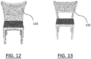
- FIG. 12 shows an example of the result of applying S50 the decoder to the optimized latent vector.
- the chair 120 is a mesh representing a plausible chair that fits the deformation constraint defined by the user.
- the method may further comprise computing S60 a deformation from the reconstructed chair 110 of FIG. 11 to the chair 120 fitting the deformation constraint.
- the result of applying S70 the deformation to the chair 100 is a plausible chair 130 that respects both the deformation constraints and the initial shape of chair 100.
- the method may retarget the deformations between g ( z 0 ) (illustrated by chair 100) and g ( ⁇ ) (illustrated by chair 120) to the original chair x.
- the method may use RBF interpolation to compute the deformation field ⁇ between g ( z 0 ) and g ( ⁇ ) .
- the technique may be the same as the previously discussed RBF interpolation, except that the method may not use any control points, but instead may compute the deformation field using directly the vertices of the reconstruction (or a characteristic subset of these vertices).
- the final edited mesh 130 is simply given by the deformation field applied to the original mesh x : x + ⁇ x
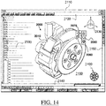
- FIG. 14 shows an example of the GUI of the system, wherein the system is a CAD system.
- the GUI 2100 may be a typical CAD-like interface, having standard menu bars 2110, 2120, as well as bottom and side toolbars 2140, 2150.
- Such menu- and toolbars contain a set of user-selectable icons, each icon being associated with one or more operations or functions, as known in the art.
- Some of these icons are associated with software tools, adapted for editing and/or working on the 3D modeled object 2000 displayed in the GUI 2100.
- the software tools may be grouped into workbenches. Each workbench comprises a subset of software tools. In particular, one of the workbenches is an edition workbench, suitable for editing geometrical features of the modeled product 2000.
- a designer may for example pre-select a part of the object 2000 and then initiate an operation (e.g. change the dimension, color, etc.) or edit geometrical constraints by selecting an appropriate icon.
- typical CAD operations are the modeling of the punching or the folding of the 3D modeled object displayed on the screen.
- the GUI may for example display data 2500 related to the displayed product 2000.
- the data 2500, displayed as a "feature tree", and their 3D representation 2000 pertain to a brake assembly including brake caliper and disc.
- the GUI may further show various types of graphic tools 2130, 2070, 2080 for example for facilitating 3D orientation of the object, for triggering a simulation of an operation of an edited product or render various attributes of the displayed product 2000.
- a cursor 2060 may be controlled by a haptic device to allow the user to interact with the graphic tools.
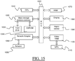
- FIG. 15 shows an example of the system, wherein the system is a client computer system, e.g. a workstation of a user.
- the system is a client computer system, e.g. a workstation of a user.
- the client computer of the example comprises a central processing unit (CPU) 1010 connected to an internal communication BUS 1000, a random access memory (RAM) 1070 also connected to the BUS.
- the client computer is further provided with a graphical processing unit (GPU) 1110 which is associated with a video random access memory 1100 connected to the BUS.
- Video RAM 1100 is also known in the art as frame buffer.
- a mass storage device controller 1020 manages accesses to a mass memory device, such as hard drive 1030.
- Mass memory devices suitable for tangibly embodying computer program instructions and data include all forms of nonvolatile memory, including by way of example semiconductor memory devices, such as EPROM, EEPROM, and flash memory devices; magnetic disks such as internal hard disks and removable disks; magneto-optical disks; and CD-ROM disks 1040. Any of the foregoing may be supplemented by, or incorporated in, specially designed ASICs (application-specific integrated circuits).
- a network adapter 1050 manages accesses to a network 1060.
- the client computer may also include a haptic device 1090 such as cursor control device, a keyboard or the like.
- a cursor control device is used in the client computer to permit the user to selectively position a cursor at any desired location on display 1080.
- the cursor control device allows the user to select various commands, and input control signals.
- the cursor control device includes a number of signal generation devices for input control signals to system.
- a cursor control device may be a mouse, the button of the mouse being used to generate the signals.
- the client computer system may comprise a sensitive pad, and/or a sensitive screen.
- the computer program may comprise instructions executable by a computer, the instructions comprising means for causing the above system to perform the method.
- the program may be recordable on any data storage medium, including the memory of the system.
- the program may for example be implemented in digital electronic circuitry, or in computer hardware, firmware, software, or in combinations of them.
- the program may be implemented as an apparatus, for example a product tangibly embodied in a machine-readable storage device for execution by a programmable processor. Method steps may be performed by a programmable processor executing a program of instructions to perform functions of the method by operating on input data and generating output.
- the processor may thus be programmable and coupled to receive data and instructions from, and to transmit data and instructions to, a data storage system, at least one input device, and at least one output device.
- the application program may be implemented in a high-level procedural or object-oriented programming language, or in assembly or machine language if desired. In any case, the language may be a compiled or interpreted language.
- the program may be a full installation program or an update program. Application of the program on the system results in any case in instructions for performing the method.
Priority Applications (4)
| Application Number | Priority Date | Filing Date | Title |
|---|---|---|---|
| EP18306758.6A EP3671660A1 (fr) | 2018-12-20 | 2018-12-20 | Conception d'un objet modélisé 3d par l'intermédiaire d'une interaction de l'utilisateur |
| JP2019229155A JP7431028B2 (ja) | 2018-12-20 | 2019-12-19 | ユーザインタラクションを介した3dモデルオブジェクトのデサイニング |
| US16/723,884 US11556678B2 (en) | 2018-12-20 | 2019-12-20 | Designing a 3D modeled object via user-interaction |
| CN201911346243.XA CN111354074A (zh) | 2018-12-20 | 2019-12-20 | 经由用户交互来设计3d建模对象 |
Applications Claiming Priority (1)
| Application Number | Priority Date | Filing Date | Title |
|---|---|---|---|
| EP18306758.6A EP3671660A1 (fr) | 2018-12-20 | 2018-12-20 | Conception d'un objet modélisé 3d par l'intermédiaire d'une interaction de l'utilisateur |
Publications (1)
| Publication Number | Publication Date |
|---|---|
| EP3671660A1 true EP3671660A1 (fr) | 2020-06-24 |
Family
ID=65228302
Family Applications (1)
| Application Number | Title | Priority Date | Filing Date |
|---|---|---|---|
| EP18306758.6A Pending EP3671660A1 (fr) | 2018-12-20 | 2018-12-20 | Conception d'un objet modélisé 3d par l'intermédiaire d'une interaction de l'utilisateur |
Country Status (4)
| Country | Link |
|---|---|
| US (1) | US11556678B2 (fr) |
| EP (1) | EP3671660A1 (fr) |
| JP (1) | JP7431028B2 (fr) |
| CN (1) | CN111354074A (fr) |
Cited By (2)
| Publication number | Priority date | Publication date | Assignee | Title |
|---|---|---|---|---|
| DE102022108379A1 (de) | 2022-04-07 | 2023-10-12 | Dr. Ing. H.C. F. Porsche Aktiengesellschaft | Verfahren, System und Computerprogrammprodukt zum optimierten Konstruieren und/oder Designen einer technischen Komponente |
| WO2023235110A1 (fr) * | 2022-05-31 | 2023-12-07 | Snap Inc. | Forme intermodale et manipulation des couleurs |
Families Citing this family (6)
| Publication number | Priority date | Publication date | Assignee | Title |
|---|---|---|---|---|
| EP3675063A1 (fr) * | 2018-12-29 | 2020-07-01 | Dassault Systèmes | Formation d'un ensemble de données d'inférence de caractéristiques de cao solides |
| EP3675062A1 (fr) | 2018-12-29 | 2020-07-01 | Dassault Systèmes | Apprentissage d'un réseau neuronal pour l'inférence des caractéristiques de cao d'un solide |
| DE102020209994A1 (de) | 2020-08-06 | 2022-02-10 | Robert Bosch Gesellschaft mit beschränkter Haftung | Vorrichtung und computerimplementiertes Verfahren zum maschinellen Lernen |
| EP3958182A1 (fr) * | 2020-08-20 | 2022-02-23 | Dassault Systèmes | Auto-encodeur variationnel pour la production d'un modèle 3d |
| EP4012386B1 (fr) * | 2020-12-09 | 2023-07-05 | Fundació Institut de Ciències Fotòniques | Identification d'objets en 3d |
| CN115953484B (zh) * | 2023-03-13 | 2023-07-04 | 福思(杭州)智能科技有限公司 | 探测设备的参数标定方法和装置、存储介质及电子装置 |
Citations (1)
| Publication number | Priority date | Publication date | Assignee | Title |
|---|---|---|---|---|
| EP3396603A1 (fr) * | 2017-04-27 | 2018-10-31 | Dassault Systèmes | Apprentissage d'un auto-codeur |
Family Cites Families (182)
| Publication number | Priority date | Publication date | Assignee | Title |
|---|---|---|---|---|
| US4821214A (en) * | 1986-04-17 | 1989-04-11 | Brigham Young University | Computer graphics method for changing the shape of a geometric model using free-form deformation |
| US5796400A (en) * | 1995-08-07 | 1998-08-18 | Silicon Graphics, Incorporated | Volume-based free form deformation weighting |
| AU4424899A (en) * | 1998-06-08 | 1999-12-30 | Microsoft Corporation | Compression of time-dependent geometry |
| US20040068187A1 (en) * | 2000-04-07 | 2004-04-08 | Krause Norman M. | Computer-aided orthopedic surgery |
| US7113185B2 (en) * | 2002-11-14 | 2006-09-26 | Microsoft Corporation | System and method for automatically learning flexible sprites in video layers |
| US7275023B2 (en) * | 2003-01-29 | 2007-09-25 | Ford Motor Company | System and method of interactively generating a family of mesh models |
| GB0414328D0 (en) * | 2004-06-25 | 2004-07-28 | Imp College Innovations Ltd | Method of correlating internal tissue movement |
| KR100754387B1 (ko) * | 2004-12-06 | 2007-08-31 | 삼성전자주식회사 | 그래픽 컨텐츠 제작장치와 방법 및 컴퓨터 프로그램을저장하는 컴퓨터로 읽을 수 있는 기록매체 |
| US8139067B2 (en) * | 2006-07-25 | 2012-03-20 | The Board Of Trustees Of The Leland Stanford Junior University | Shape completion, animation and marker-less motion capture of people, animals or characters |
| US20080162090A1 (en) * | 2006-12-27 | 2008-07-03 | Ernest Clay Perry | System, methods, and computer readable media, for product design using t-spline deformation |
| US20080275677A1 (en) * | 2007-03-19 | 2008-11-06 | Optimal Solutions Software, Llc | System, methods, and computer readable media, for product design using coupled computer aided engineering models |
| US20160328998A1 (en) * | 2008-03-17 | 2016-11-10 | Worcester Polytechnic Institute | Virtual interactive system for ultrasound training |
| US8737721B2 (en) * | 2008-05-07 | 2014-05-27 | Microsoft Corporation | Procedural authoring |
| EP2327061A4 (fr) * | 2008-08-15 | 2016-11-16 | Univ Brown | Procédé et appareil pour estimer la forme du corps |
| US9024938B2 (en) * | 2011-07-29 | 2015-05-05 | Adobe Systems Incorporated | Methods and apparatus for sweep-based freeform deformation of 3-D models |
| US8994736B2 (en) * | 2011-09-23 | 2015-03-31 | Adobe Systems Incorporated | Methods and apparatus for freeform deformation of 3-D models |
| US8666119B1 (en) * | 2011-11-29 | 2014-03-04 | Lucasfilm Entertainment Company Ltd. | Geometry tracking |
| US9779546B2 (en) * | 2012-05-04 | 2017-10-03 | Intermec Ip Corp. | Volume dimensioning systems and methods |
| US11521223B2 (en) * | 2012-10-23 | 2022-12-06 | Protolabs, Inc. | Automated fabrication price quoting and fabrication ordering for computer-modeled structures |
| RU2530220C1 (ru) * | 2013-03-18 | 2014-10-10 | Корпорация "САМСУНГ ЭЛЕКТРОНИКС Ко., Лтд." | Система и способ для автоматической регистрации анатомических точек в объемных медицинских изображениях |
| WO2014177906A1 (fr) * | 2013-04-30 | 2014-11-06 | Dassault Systèmes Simulia Corp. | Génération d'un modèle cao à partir d'une maille d'éléments finis |
| WO2014193670A2 (fr) * | 2013-05-29 | 2014-12-04 | Capso Vision, Inc. | Reconstruction d'images provenant d'une capsule à plusieurs caméras pour imagerie in vivo |
| US9378576B2 (en) * | 2013-06-07 | 2016-06-28 | Faceshift Ag | Online modeling for real-time facial animation |
| US9406142B2 (en) * | 2013-10-08 | 2016-08-02 | The Trustees Of The University Of Pennsylvania | Fully automatic image segmentation of heart valves using multi-atlas label fusion and deformable medial modeling |
| WO2015061914A1 (fr) * | 2013-11-04 | 2015-05-07 | The University Of British Columbia | Procédés et systèmes de génération de segmentations polycube à partir de maillages d'objets d'entrée |
| US9710964B2 (en) * | 2014-01-23 | 2017-07-18 | Max-Planck-Gesellschaft Zur Foerderung Der Wissenschaften E.V. | Method for providing a three dimensional body model |
| US9524582B2 (en) * | 2014-01-28 | 2016-12-20 | Siemens Healthcare Gmbh | Method and system for constructing personalized avatars using a parameterized deformable mesh |
| CA3085892A1 (fr) * | 2014-07-10 | 2016-01-14 | Mohamed R. Mahfouz | Navigation tka coudee |
| WO2016015108A1 (fr) * | 2014-08-01 | 2016-02-04 | Katholieke Universiteit Leuven | Système d'interprétation de motifs d'image en termes de modèles anatomiques ou organisés |
| US11127163B2 (en) * | 2015-06-24 | 2021-09-21 | Fraunhofer-Gesellschaft zur Förderung der angewandten Forschung e.V. | Skinned multi-infant linear body model |
| US10395411B2 (en) * | 2015-06-24 | 2019-08-27 | MAX-PLANCK-Gesellschaft zur Förderung der Wissenschaften e.V. | Skinned multi-person linear model |
| US10474950B2 (en) * | 2015-06-29 | 2019-11-12 | Microsoft Technology Licensing, Llc | Training and operation of computational models |
| US9928663B2 (en) * | 2015-07-27 | 2018-03-27 | Technische Universiteit Delft | Skeletal joint optimization for linear blend skinning deformations utilizing skeletal pose sampling |
| WO2017027957A1 (fr) | 2015-08-17 | 2017-02-23 | Side Effects Software Inc. | Procédés de simulation physique permettant de modéliser et d'animer des objets déformables bi- et tri-dimensionnels |
| US10521902B2 (en) * | 2015-10-14 | 2019-12-31 | The Regents Of The University Of California | Automated segmentation of organ chambers using deep learning methods from medical imaging |
| JP6993334B2 (ja) * | 2015-11-29 | 2022-01-13 | アーテリーズ インコーポレイテッド | 自動化された心臓ボリュームセグメンテーション |
| CN105447872A (zh) * | 2015-12-03 | 2016-03-30 | 中山大学 | 一种在超声影像中自动识别肝脏肿瘤类型的方法 |
| EP3188033B1 (fr) | 2015-12-31 | 2024-02-14 | Dassault Systèmes | Reconstruction d'un objet modélisé 3d |
| EP3188039A1 (fr) * | 2015-12-31 | 2017-07-05 | Dassault Systèmes | Recommandations sur la base de modèle prédictif |
| US10262448B2 (en) * | 2016-01-19 | 2019-04-16 | Dreamworks Animation L.L.C. | Repurposing existing animated content |
| US10628537B2 (en) * | 2016-04-12 | 2020-04-21 | Dassault Systemes Simulia Corp. | Simulation augmented reality system for emergent behavior |
| EP3264286B1 (fr) * | 2016-06-28 | 2020-11-18 | Dassault Systèmes | Interrogation d'une base de données à l'aide de critère morphologique |
| US10395372B2 (en) * | 2016-06-28 | 2019-08-27 | University Of Cincinnati | Systems, media, and methods for pre-processing and post-processing in additive manufacturing |
| CN110494895B (zh) * | 2016-08-19 | 2023-09-19 | 莫维迪厄斯有限公司 | 使用稀疏体积数据的渲染操作 |
| US10878136B2 (en) * | 2016-09-14 | 2020-12-29 | Mixed Dimensions Inc. | 3D model validation and optimization system and method thereof |
| US10460511B2 (en) * | 2016-09-23 | 2019-10-29 | Blue Vision Labs UK Limited | Method and system for creating a virtual 3D model |
| US20180095450A1 (en) * | 2016-09-30 | 2018-04-05 | Velo3D, Inc. | Three-dimensional objects and their formation |
| US10902343B2 (en) * | 2016-09-30 | 2021-01-26 | Disney Enterprises, Inc. | Deep-learning motion priors for full-body performance capture in real-time |
| EP3327593B1 (fr) * | 2016-11-25 | 2022-02-09 | Dassault Systèmes | Orientation d'un objet réel pour impression 3d |
| WO2018101936A1 (fr) * | 2016-11-30 | 2018-06-07 | CapsoVision, Inc. | Procédé et appareil destinés à l'assemblage d'images capturées à l'aide d'une caméra à capsule |
| EP3340085B1 (fr) * | 2016-12-23 | 2021-11-03 | Dassault Systèmes | B-rep du résultat d'un processus d'impression 3d à deux axes |
| CN106960459B (zh) * | 2016-12-26 | 2019-07-26 | 北京航空航天大学 | 角色动画中基于扩展位置动力学的蒙皮技术及权重重定位的方法 |
| US10163003B2 (en) | 2016-12-28 | 2018-12-25 | Adobe Systems Incorporated | Recognizing combinations of body shape, pose, and clothing in three-dimensional input images |
| JP2020510463A (ja) * | 2017-01-27 | 2020-04-09 | アーテリーズ インコーポレイテッド | 全層畳み込みネットワークを利用する自動化されたセグメンテーション |
| US10810793B2 (en) * | 2017-03-13 | 2020-10-20 | Technion Research & Development Foundation Limited | Microstructures and porous geometry modeling |
| US10475165B2 (en) * | 2017-04-06 | 2019-11-12 | Disney Enterprises, Inc. | Kernel-predicting convolutional neural networks for denoising |
| EP3416103A1 (fr) * | 2017-06-16 | 2018-12-19 | Dassault Systèmes | Ensemble de données pour l'apprentissage d'une fonction de prise d'images en tant qu'entrées |
| US10783393B2 (en) * | 2017-06-20 | 2020-09-22 | Nvidia Corporation | Semi-supervised learning for landmark localization |
| US11501429B2 (en) * | 2017-07-19 | 2022-11-15 | Altius Institute For Biomedical Sciences | Methods of analyzing microscopy images using machine learning |
| EP3444735A1 (fr) * | 2017-08-17 | 2019-02-20 | Universität Stuttgart | Procédé et module pour transformer la forme d'un objet |
| US20190073580A1 (en) * | 2017-09-01 | 2019-03-07 | Facebook, Inc. | Sparse Neural Network Modeling Infrastructure |
| US10943171B2 (en) * | 2017-09-01 | 2021-03-09 | Facebook, Inc. | Sparse neural network training optimization |
| US11144812B2 (en) * | 2017-09-01 | 2021-10-12 | Facebook, Inc. | Mixed machine learning architecture |
| US11132604B2 (en) * | 2017-09-01 | 2021-09-28 | Facebook, Inc. | Nested machine learning architecture |
| EP3460760B1 (fr) * | 2017-09-26 | 2021-05-19 | Dassault Systèmes | Génération d'un dessin 2d représentant une pièce mécanique |
| EP3467717A1 (fr) * | 2017-10-04 | 2019-04-10 | Prowler.io Limited | Système d'apprentissage par machine |
| EP3474185B1 (fr) * | 2017-10-18 | 2023-06-28 | Dassault Systèmes | Classification d'images 2d selon les types d'agencement 3d |
| EP3483755B1 (fr) * | 2017-11-09 | 2022-07-13 | Dassault Systèmes | Fabrication additive d'une pièce 3d |
| US11080886B2 (en) * | 2017-11-15 | 2021-08-03 | Qualcomm Incorporated | Learning disentangled invariant representations for one shot instance recognition |
| US11170301B2 (en) * | 2017-11-16 | 2021-11-09 | Mitsubishi Electric Research Laboratories, Inc. | Machine learning via double layer optimization |
| US11403813B2 (en) * | 2019-11-26 | 2022-08-02 | Sdc U.S. Smilepay Spv | Systems and methods for constructing a three-dimensional model from two-dimensional images |
| US11443178B2 (en) * | 2017-12-15 | 2022-09-13 | Interntional Business Machines Corporation | Deep neural network hardening framework |
| US11145291B2 (en) * | 2018-01-31 | 2021-10-12 | Microsoft Technology Licensing, Llc | Training natural language system with generated dialogues |
| US10861440B2 (en) * | 2018-02-05 | 2020-12-08 | Microsoft Technology Licensing, Llc | Utterance annotation user interface |
| US20190251744A1 (en) * | 2018-02-12 | 2019-08-15 | Express Search, Inc. | System and method for searching 3d models using 2d images |
| US10719742B2 (en) * | 2018-02-15 | 2020-07-21 | Adobe Inc. | Image composites using a generative adversarial neural network |
| CN111788589A (zh) * | 2018-02-23 | 2020-10-16 | Asml荷兰有限公司 | 训练用于计算光刻术的机器学习模型的方法 |
| US11133001B2 (en) * | 2018-03-20 | 2021-09-28 | Microsoft Technology Licensing, Llc | Generating dialogue events for natural language system |
| US10755215B2 (en) * | 2018-03-22 | 2020-08-25 | International Business Machines Corporation | Generating wastage estimation using multiple orientation views of a selected product |
| US20210074036A1 (en) * | 2018-03-23 | 2021-03-11 | Memorial Sloan Kettering Cancer Center | Deep encoder-decoder models for reconstructing biomedical images |
| EP3756139A1 (fr) * | 2018-04-12 | 2020-12-30 | DeepMind Technologies Limited | Réseaux neuronaux de graphe représentant des systèmes physiques |
| US10950021B2 (en) * | 2018-04-23 | 2021-03-16 | Accenture Global Solutions Limited | AI-driven design platform |
| WO2019207176A1 (fr) * | 2018-04-25 | 2019-10-31 | Seddi, Inc. | Modélisation de la dynamique de tissu mou non linéaire pour des avatars interactifs |
| US10810460B2 (en) * | 2018-06-13 | 2020-10-20 | Cosmo Artificial Intelligence—AI Limited | Systems and methods for training generative adversarial networks and use of trained generative adversarial networks |
| US11100633B2 (en) * | 2018-06-13 | 2021-08-24 | Cosmo Artificial Intelligence—Al Limited | Systems and methods for processing real-time video from a medical image device and detecting objects in the video |
| US10984606B1 (en) * | 2018-06-21 | 2021-04-20 | Dassault Systemes Solidworks Corporation | Graphical user interface tool for orienting computer-aided design model |
| US10909746B1 (en) * | 2018-06-22 | 2021-02-02 | Imbellus, Inc. | Systems and methods for asset generation in immersive cognitive assessments |
| US11756160B2 (en) * | 2018-07-27 | 2023-09-12 | Washington University | ML-based methods for pseudo-CT and HR MR image estimation |
| US10861225B2 (en) * | 2018-08-10 | 2020-12-08 | Intel Corporation | Neural network processing for multi-object 3D modeling |
| US11568864B2 (en) * | 2018-08-13 | 2023-01-31 | Carnegie Mellon University | Processing speech signals of a user to generate a visual representation of the user |
| US10664979B2 (en) * | 2018-09-14 | 2020-05-26 | Siemens Healthcare Gmbh | Method and system for deep motion model learning in medical images |
| US11109065B2 (en) * | 2018-09-26 | 2021-08-31 | Google Llc | Video encoding by providing geometric proxies |
| US11126915B2 (en) * | 2018-10-15 | 2021-09-21 | Sony Corporation | Information processing apparatus and information processing method for volume data visualization |
| US20210345970A1 (en) * | 2018-10-15 | 2021-11-11 | University Of Louisville Research Foundation, Inc. | Computer aided diagnostic systems and methods for detection of cancer |
| US20200139631A1 (en) * | 2018-11-07 | 2020-05-07 | Velo3D, Inc. | Data assurance in three-dimensional forming |
| US10916054B2 (en) * | 2018-11-08 | 2021-02-09 | Adobe Inc. | Three-dimensional mesh deformation using deep learning neural networks |
| WO2020102772A1 (fr) * | 2018-11-15 | 2020-05-22 | Qualcomm Incorporated | Estimation de coordonnées sur des n-sphères avec une régression sphérique |
| US10803987B2 (en) * | 2018-11-16 | 2020-10-13 | Elekta, Inc. | Real-time motion monitoring using deep neural network |
| US11457871B2 (en) * | 2018-11-21 | 2022-10-04 | Enlitic, Inc. | Medical scan artifact detection system and methods for use therewith |
| US11074751B2 (en) * | 2018-12-04 | 2021-07-27 | University Of Southern California | 3D hair synthesis using volumetric variational autoencoders |
| US11501172B2 (en) * | 2018-12-13 | 2022-11-15 | Sap Se | Accurately identifying members of training data in variational autoencoders by reconstruction error |
| US20200202622A1 (en) * | 2018-12-19 | 2020-06-25 | Nvidia Corporation | Mesh reconstruction using data-driven priors |
| US10915680B2 (en) * | 2018-12-21 | 2021-02-09 | Dassault Systemes Simulia Corp. | Local control of design patterns on surfaces for enhanced physical properties |
| US11720766B2 (en) * | 2018-12-28 | 2023-08-08 | Packsize Llc | Systems and methods for text and barcode reading under perspective distortion |
| TWI697010B (zh) * | 2018-12-28 | 2020-06-21 | 國立成功大學 | 醫療矢面影像的取得方法、神經網路的訓練方法及計算機裝置 |
| EP3675063A1 (fr) * | 2018-12-29 | 2020-07-01 | Dassault Systèmes | Formation d'un ensemble de données d'inférence de caractéristiques de cao solides |
| EP3675061A1 (fr) * | 2018-12-29 | 2020-07-01 | Dassault Systèmes | Formation d'un ensemble de données pour l'inférence d'arbres de caractéristiques modifiables |
| EP3675062A1 (fr) * | 2018-12-29 | 2020-07-01 | Dassault Systèmes | Apprentissage d'un réseau neuronal pour l'inférence des caractéristiques de cao d'un solide |
| EP3674983A1 (fr) * | 2018-12-29 | 2020-07-01 | Dassault Systèmes | Apprentissage machine pour inférence d'objet modélisé 3d |
| EP3674984A1 (fr) * | 2018-12-29 | 2020-07-01 | Dassault Systèmes | Ensemble de réseaux neuronaux |
| US20200226407A1 (en) * | 2019-01-16 | 2020-07-16 | Rok Mobile International Ltd. | Delivery of digital content customized using images of objects |
| WO2020155522A1 (fr) * | 2019-01-31 | 2020-08-06 | Huawei Technologies Co., Ltd. | Détection personnalisée d'objet domestique avec assistance tridimensionnelle (3d) |
| US11321918B2 (en) * | 2019-02-27 | 2022-05-03 | 3Shape A/S | Method for manipulating 3D objects by flattened mesh |
| CN109993825B (zh) * | 2019-03-11 | 2023-06-20 | 北京工业大学 | 一种基于深度学习的三维重建方法 |
| US11049308B2 (en) * | 2019-03-21 | 2021-06-29 | Electronic Arts Inc. | Generating facial position data based on audio data |
| US11388416B2 (en) * | 2019-03-21 | 2022-07-12 | Qualcomm Incorporated | Video compression using deep generative models |
| US10692277B1 (en) * | 2019-03-21 | 2020-06-23 | Adobe Inc. | Dynamically estimating lighting parameters for positions within augmented-reality scenes using a neural network |
| CN109961507B (zh) * | 2019-03-22 | 2020-12-18 | 腾讯科技(深圳)有限公司 | 一种人脸图像生成方法、装置、设备及存储介质 |
| US11288857B2 (en) * | 2019-04-04 | 2022-03-29 | Google Llc | Neural rerendering from 3D models |
| US11062502B2 (en) * | 2019-04-09 | 2021-07-13 | Facebook Technologies, Llc | Three-dimensional modeling volume for rendering images |
| KR102191007B1 (ko) * | 2019-04-19 | 2020-12-14 | 한국과학기술원 | 3 차원 이미지 생성 방법 및 장치 |
| US20200342968A1 (en) * | 2019-04-24 | 2020-10-29 | GE Precision Healthcare LLC | Visualization of medical device event processing |
| US10818043B1 (en) * | 2019-04-24 | 2020-10-27 | Adobe Inc. | Texture interpolation using neural networks |
| US20200349482A1 (en) * | 2019-05-02 | 2020-11-05 | Autodesk, Inc. | Techniques for workflow analysis and design task optimization |
| US11238586B2 (en) * | 2019-05-02 | 2022-02-01 | Align Technology, Inc. | Excess material removal using machine learning |
| US10504005B1 (en) * | 2019-05-10 | 2019-12-10 | Capital One Services, Llc | Techniques to embed a data object into a multidimensional frame |
| US11080884B2 (en) * | 2019-05-15 | 2021-08-03 | Matterport, Inc. | Point tracking using a trained network |
| US11367188B2 (en) * | 2019-10-18 | 2022-06-21 | Retrace Labs | Dental image synthesis using generative adversarial networks with semantic activation blocks |
| US11670001B2 (en) * | 2019-05-17 | 2023-06-06 | Nvidia Corporation | Object pose estimation |
| US10769848B1 (en) * | 2019-05-24 | 2020-09-08 | Adobe, Inc. | 3D object reconstruction using photometric mesh representation |
| US11030772B2 (en) * | 2019-06-03 | 2021-06-08 | Microsoft Technology Licensing, Llc | Pose synthesis |
| US11790213B2 (en) * | 2019-06-12 | 2023-10-17 | Sri International | Identifying complex events from hierarchical representation of data set features |
| US11551038B2 (en) * | 2019-07-01 | 2023-01-10 | Adobe Inc. | Unified shape representation |
| US10922877B2 (en) * | 2019-07-01 | 2021-02-16 | Samsung Electronics Co., Ltd. | Higher-order function networks for learning composable three-dimensional (3D) object and operating method thereof |
| KR20210003514A (ko) * | 2019-07-02 | 2021-01-12 | 한국전자통신연구원 | 오디오의 고대역 부호화 방법 및 고대역 복호화 방법, 그리고 상기 방법을 수하는 부호화기 및 복호화기 |
| EP3764269A1 (fr) * | 2019-07-07 | 2021-01-13 | Dassault Systèmes | Modélisation des opérations sur des structures fonctionnelles |
| US20210012486A1 (en) * | 2019-07-09 | 2021-01-14 | Shenzhen Malong Technologies Co., Ltd. | Image synthesis with generative adversarial network |
| US11704853B2 (en) * | 2019-07-15 | 2023-07-18 | Disney Enterprises, Inc. | Techniques for feature-based neural rendering |
| US11475275B2 (en) * | 2019-07-18 | 2022-10-18 | International Business Machines Corporation | Recurrent autoencoder for chromatin 3D structure prediction |
| CN113096234B (zh) * | 2019-12-23 | 2022-09-06 | 复旦大学 | 利用多张彩色图片生成三维网格模型的方法及装置 |
| WO2021016596A1 (fr) * | 2019-07-25 | 2021-01-28 | Nvidia Corporation | Réseau neuronal profond servant à la segmentation de scènes de la route et d'instances d'objets animés pour des applications de conduite autonome |
| US11954610B2 (en) * | 2019-08-09 | 2024-04-09 | GE Precision Healthcare LLC | Active surveillance and learning for machine learning model authoring and deployment |
| US11062495B2 (en) * | 2019-08-09 | 2021-07-13 | Disney Enterprises, Inc. | Systems and methods for partitioning an animatable model |
| US11613201B2 (en) * | 2019-08-12 | 2023-03-28 | Nvidia Corporation | Automatic high beam control for autonomous machine applications |
| US10803646B1 (en) * | 2019-08-19 | 2020-10-13 | Neon Evolution Inc. | Methods and systems for image and voice processing |
| US10949715B1 (en) * | 2019-08-19 | 2021-03-16 | Neon Evolution Inc. | Methods and systems for image and voice processing |
| KR20190106867A (ko) * | 2019-08-27 | 2019-09-18 | 엘지전자 주식회사 | 가구의 배치 위치를 가이드하는 인공 지능 장치 및 그의 동작 방법 |
| KR20190106855A (ko) * | 2019-08-27 | 2019-09-18 | 엘지전자 주식회사 | Xr 디바이스 및 그 제어 방법 |
| US11100643B2 (en) * | 2019-09-11 | 2021-08-24 | Nvidia Corporation | Training strategy search using reinforcement learning |
| KR20210035381A (ko) * | 2019-09-23 | 2021-04-01 | 삼성에스디에스 주식회사 | 의료 진단 방법 및 장치 |
| US11069131B2 (en) * | 2019-09-26 | 2021-07-20 | Amazon Technologies, Inc. | Predictive personalized three-dimensional body models |
| US11574353B2 (en) * | 2019-10-09 | 2023-02-07 | Target Brands, Inc. | Compatibility based furniture recommendations |
| US11294996B2 (en) * | 2019-10-15 | 2022-04-05 | Assa Abloy Ab | Systems and methods for using machine learning for image-based spoof detection |
| US20210133990A1 (en) * | 2019-11-05 | 2021-05-06 | Nvidia Corporation | Image aligning neural network |
| US11724401B2 (en) * | 2019-11-13 | 2023-08-15 | Nvidia Corporation | Grasp determination for an object in clutter |
| US11663746B2 (en) * | 2019-11-15 | 2023-05-30 | Intel Corporation | Systolic arithmetic on sparse data |
| US11676310B2 (en) * | 2019-11-16 | 2023-06-13 | Uatc, Llc | System and methods for encoding octree structured point cloud data using an entropy model |
| US11055616B2 (en) * | 2019-11-18 | 2021-07-06 | UMNAI Limited | Architecture for an explainable neural network |
| US20210146531A1 (en) * | 2019-11-20 | 2021-05-20 | Nvidia Corporation | Guided uncertainty-aware policy optimization: combining model-free and model-based strategies for sample-efficient learning |
| US11282218B2 (en) * | 2019-11-25 | 2022-03-22 | Shanghai United Imaging Intelligence Co., Ltd. | Systems and methods for providing medical guidance using a patient depth image |
| US11735306B2 (en) * | 2019-11-25 | 2023-08-22 | Dentsply Sirona Inc. | Method, system and computer readable storage media for creating three-dimensional dental restorations from two dimensional sketches |
| US10691133B1 (en) * | 2019-11-26 | 2020-06-23 | Apex Artificial Intelligence Industries, Inc. | Adaptive and interchangeable neural networks |
| US20210166477A1 (en) * | 2019-12-03 | 2021-06-03 | Augustus Intelligence Inc. | Synthesizing images from 3d models |
| EP3859610A1 (fr) * | 2020-01-30 | 2021-08-04 | Dassault Systèmes | Apprentissage de bases de déformations |
| EP3872771A1 (fr) * | 2020-02-25 | 2021-09-01 | Dassault Systèmes | Détermination de déformation d'un objet modélisé en 3d |
| CN115191005A (zh) * | 2020-03-05 | 2022-10-14 | 奇跃公司 | 用于从多视图图像进行端到端场景重建的系统和方法 |
| US10937237B1 (en) * | 2020-03-11 | 2021-03-02 | Adobe Inc. | Reconstructing three-dimensional scenes using multi-view cycle projection |
| US11783198B2 (en) * | 2020-04-03 | 2023-10-10 | Baidu Usa Llc | Estimating the implicit likelihoods of generative adversarial networks |
| US20210350620A1 (en) * | 2020-05-07 | 2021-11-11 | Imperial College Innovations Limited | Generative geometric neural networks for 3d shape modelling |
| US11348314B2 (en) * | 2020-05-08 | 2022-05-31 | Dreamworks Animation Llc | Fast and deep facial deformations |
| US11443484B2 (en) * | 2020-05-15 | 2022-09-13 | Microsoft Technology Licensing, Llc | Reinforced differentiable attribute for 3D face reconstruction |
| US11485308B2 (en) * | 2020-06-29 | 2022-11-01 | Nvidia Corporation | In-cabin hazard prevention and safety control system for autonomous machine applications |
| US20220005150A1 (en) * | 2020-07-02 | 2022-01-06 | Korea Advanced Institute Of Science And Technology | Unsupervised deformable image registration method using cycle-consistent neural network and apparatus therefor |
| US11645813B2 (en) * | 2020-07-06 | 2023-05-09 | Disney Enterprises, Inc. | Techniques for sculpting digital faces based on anatomical modeling |
| US11164069B1 (en) * | 2020-07-08 | 2021-11-02 | NotCo Delaware, LLC | Controllable formula generation |
| US11335062B2 (en) * | 2020-08-14 | 2022-05-17 | Accenture Global Solutions Limited | Automated apparel design using machine learning |
| US20220051094A1 (en) * | 2020-08-14 | 2022-02-17 | Nvidia Corporation | Mesh based convolutional neural network techniques |
| US20200402243A1 (en) * | 2020-09-03 | 2020-12-24 | Intel Corporation | Video background estimation using spatio-temporal models |
| US10930066B1 (en) * | 2020-09-11 | 2021-02-23 | Mythical, Inc. | Systems and methods for using natural language processing (NLP) to automatically generate three-dimensional objects in a virtual space |
| US11924445B2 (en) * | 2020-09-25 | 2024-03-05 | Qualcomm Incorporated | Instance-adaptive image and video compression using machine learning systems |
| US11409633B2 (en) * | 2020-10-16 | 2022-08-09 | Wipro Limited | System and method for auto resolution of errors during compilation of data segments |
| US11308657B1 (en) * | 2021-08-11 | 2022-04-19 | Neon Evolution Inc. | Methods and systems for image processing using a learning engine |
-
2018
- 2018-12-20 EP EP18306758.6A patent/EP3671660A1/fr active Pending
-
2019
- 2019-12-19 JP JP2019229155A patent/JP7431028B2/ja active Active
- 2019-12-20 CN CN201911346243.XA patent/CN111354074A/zh active Pending
- 2019-12-20 US US16/723,884 patent/US11556678B2/en active Active
Patent Citations (1)
| Publication number | Priority date | Publication date | Assignee | Title |
|---|---|---|---|---|
| EP3396603A1 (fr) * | 2017-04-27 | 2018-10-31 | Dassault Systèmes | Apprentissage d'un auto-codeur |
Non-Patent Citations (13)
| Title |
|---|
| A. BROCK; T. LIM; J.M. RITCHIE: "Neural Photo Editing with Introspective Adversarial Networks", ICLR, 2017 |
| G.E. HINTON; R.R. SALAKHUTDINOV: "Reducing the Dimensionality of Data with Neural Networks", SCIENCE, 2006 |
| H. LI, R; SUMNER; M. PAULY: "Global Correspondence Optimization for Non-Rigid Registration of Depth Scans", COMPUT. GRAPH. FORUM, vol. 27, no. 5, 2008, pages 1421 - 1430 |
| H. LI; R. SUMNER; M. PAULY: "Global Correspondence Optimization for Non-Rigid Registration of Depth Scans", COMPUT. GRAPH. FORUM, vol. 27, no. 5, 2008, pages 1421 - 1430 |
| I. GOODFELLOW; J. POUGET-ABADIE; M. MIRZA; B. XU; D. WARDE-FARLEY; S. OZAIR; A. COURVILLE; Y. BENGIO: "Generative Adversarial Nets", ADVANCES IN NEURAL INFORMATION PROCESSING SYSTEMS, 2014 |
| JERRY LIU ET AL: "Interactive 3D Modeling with a Generative Adversarial Network", ARXIV.ORG, CORNELL UNIVERSITY LIBRARY, 201 OLIN LIBRARY CORNELL UNIVERSITY ITHACA, NY 14853, 16 June 2017 (2017-06-16), XP080770297, DOI: 10.1109/3DV.2017.00024 * |
| JUN-YAN ZHU ET AL: "Generative Visual Manipulation on the Natural Image Manifold", ARXIV.ORG, CORNELL UNIVERSITY LIBRARY, 201 OLIN LIBRARY CORNELL UNIVERSITY ITHACA, NY 14853, 12 September 2016 (2016-09-12), XP080996244 * |
| J-Y ZHU; P. KRAHENBUHL; E. SHECHTMAN; A. A. EFROS: "Generative Visual Manipulation on the Natural Image Manifold", ECCV, 2016 |
| P. VINCENT; H. LARCOHELLE; I. LAJOIE; Y. BENGIO; P. MANZAGOL: "Stacked Denoising Autoencoders: Learning Useful Representations in a Deep Network with a Local Denoising Criterion", THE JOURNAL OF MACHINE LEARNING RESEARCH, 2010 |
| QINGYANG TAN ET AL: "Mesh-based Autoencoders for Localized Deformation Component Analysis", ARXIV.ORG, CORNELL UNIVERSITY LIBRARY, 201 OLIN LIBRARY CORNELL UNIVERSITY ITHACA, NY 14853, 13 September 2017 (2017-09-13), XP080820792 * |
| TAN QINGYANG ET AL: "Variational Autoencoders for Deforming 3D Mesh Models", 2018 IEEE/CVF CONFERENCE ON COMPUTER VISION AND PATTERN RECOGNITION, IEEE, 18 June 2018 (2018-06-18), pages 5841 - 5850, XP033473499, DOI: 10.1109/CVPR.2018.00612 * |
| Y. BENGIO: "Learning Deep Architectures for Al", FOUNDATIONS AND TRENDS IN MACHINE LEARNING, 2009 |
| YUMER M ERSIN ET AL: "Learning Semantic Deformation Flows with 3D Convolutional Networks", 17 September 2016, PROC. INT.CONF. ADV. BIOMETRICS (ICB); [LECTURE NOTES IN COMPUTER SCIENCE; LECT.NOTES COMPUTER], SPRINGER, BERLIN, HEIDELBERG, PAGE(S) 294 - 311, ISBN: 978-3-642-17318-9, XP047355304 * |
Cited By (2)
| Publication number | Priority date | Publication date | Assignee | Title |
|---|---|---|---|---|
| DE102022108379A1 (de) | 2022-04-07 | 2023-10-12 | Dr. Ing. H.C. F. Porsche Aktiengesellschaft | Verfahren, System und Computerprogrammprodukt zum optimierten Konstruieren und/oder Designen einer technischen Komponente |
| WO2023235110A1 (fr) * | 2022-05-31 | 2023-12-07 | Snap Inc. | Forme intermodale et manipulation des couleurs |
Also Published As
| Publication number | Publication date |
|---|---|
| US11556678B2 (en) | 2023-01-17 |
| US20200202045A1 (en) | 2020-06-25 |
| JP7431028B2 (ja) | 2024-02-14 |
| JP2020102215A (ja) | 2020-07-02 |
| CN111354074A (zh) | 2020-06-30 |
Similar Documents
| Publication | Publication Date | Title |
|---|---|---|
| US11556678B2 (en) | Designing a 3D modeled object via user-interaction | |
| US11468268B2 (en) | Learning an autoencoder | |
| US11443192B2 (en) | Machine-learning for 3D modeled object inference | |
| US11562207B2 (en) | Set of neural networks | |
| EP3188033B1 (fr) | Reconstruction d'un objet modélisé 3d | |
| US11922573B2 (en) | Learning a neural network for inference of solid CAD features | |
| US11514214B2 (en) | Forming a dataset for inference of solid CAD features | |
| US11869147B2 (en) | Neural network for outputting a parameterized 3D model | |
| US10719549B2 (en) | Querying a database based on a parametric view function | |
| US20220058865A1 (en) | Variational auto-encoder for outputting a 3d model | |
| US20220101105A1 (en) | Deep-learning generative model | |
| US20210264079A1 (en) | Determining a 3d modeled object deformation | |
| US20210241106A1 (en) | Deformations basis learning | |
| US20200134245A1 (en) | 3d design of b-rep skin | |
| US20190197775A1 (en) | Determining a set of facets that represents a skin of a real object | |
| US20230342507A1 (en) | 3d reconstruction from images |
Legal Events
| Date | Code | Title | Description |
|---|---|---|---|
| PUAI | Public reference made under article 153(3) epc to a published international application that has entered the european phase |
Free format text: ORIGINAL CODE: 0009012 |
|
| STAA | Information on the status of an ep patent application or granted ep patent |
Free format text: STATUS: THE APPLICATION HAS BEEN PUBLISHED |
|
| AK | Designated contracting states |
Kind code of ref document: A1 Designated state(s): AL AT BE BG CH CY CZ DE DK EE ES FI FR GB GR HR HU IE IS IT LI LT LU LV MC MK MT NL NO PL PT RO RS SE SI SK SM TR |
|
| AX | Request for extension of the european patent |
Extension state: BA ME |
|
| STAA | Information on the status of an ep patent application or granted ep patent |
Free format text: STATUS: REQUEST FOR EXAMINATION WAS MADE |
|
| 17P | Request for examination filed |
Effective date: 20210111 |
|
| RBV | Designated contracting states (corrected) |
Designated state(s): AL AT BE BG CH CY CZ DE DK EE ES FI FR GB GR HR HU IE IS IT LI LT LU LV MC MK MT NL NO PL PT RO RS SE SI SK SM TR |
|
| STAA | Information on the status of an ep patent application or granted ep patent |
Free format text: STATUS: EXAMINATION IS IN PROGRESS |
|
| 17Q | First examination report despatched |
Effective date: 20220513 |