EP3671377A1 - Device to be mounted on a covering installation - Google Patents
Device to be mounted on a covering installation Download PDFInfo
- Publication number
- EP3671377A1 EP3671377A1 EP19216958.9A EP19216958A EP3671377A1 EP 3671377 A1 EP3671377 A1 EP 3671377A1 EP 19216958 A EP19216958 A EP 19216958A EP 3671377 A1 EP3671377 A1 EP 3671377A1
- Authority
- EP
- European Patent Office
- Prior art keywords
- tubular shaft
- casing
- receiver
- audio signals
- amplifier
- Prior art date
- Legal status (The legal status is an assumption and is not a legal conclusion. Google has not performed a legal analysis and makes no representation as to the accuracy of the status listed.)
- Granted
Links
- 238000009434 installation Methods 0.000 title claims abstract description 34
- 230000005236 sound signal Effects 0.000 claims abstract description 41
- 239000004020 conductor Substances 0.000 claims description 6
- 230000005611 electricity Effects 0.000 claims description 2
- 238000004804 winding Methods 0.000 description 4
- 230000003321 amplification Effects 0.000 description 3
- 230000005540 biological transmission Effects 0.000 description 3
- 238000004891 communication Methods 0.000 description 3
- 239000002184 metal Substances 0.000 description 3
- 238000003199 nucleic acid amplification method Methods 0.000 description 3
- 238000005096 rolling process Methods 0.000 description 3
- 230000004913 activation Effects 0.000 description 2
- 230000001413 cellular effect Effects 0.000 description 2
- 238000009792 diffusion process Methods 0.000 description 2
- 230000000694 effects Effects 0.000 description 2
- 238000003780 insertion Methods 0.000 description 2
- 230000037431 insertion Effects 0.000 description 2
- 239000004744 fabric Substances 0.000 description 1
- 230000010354 integration Effects 0.000 description 1
- 230000007257 malfunction Effects 0.000 description 1
- 238000012544 monitoring process Methods 0.000 description 1
- 230000001681 protective effect Effects 0.000 description 1
- 238000001228 spectrum Methods 0.000 description 1
- 238000003466 welding Methods 0.000 description 1
Images

Classifications
-
- G—PHYSICS
- G05—CONTROLLING; REGULATING
- G05B—CONTROL OR REGULATING SYSTEMS IN GENERAL; FUNCTIONAL ELEMENTS OF SUCH SYSTEMS; MONITORING OR TESTING ARRANGEMENTS FOR SUCH SYSTEMS OR ELEMENTS
- G05B15/00—Systems controlled by a computer
- G05B15/02—Systems controlled by a computer electric
-
- E—FIXED CONSTRUCTIONS
- E04—BUILDING
- E04F—FINISHING WORK ON BUILDINGS, e.g. STAIRS, FLOORS
- E04F10/00—Sunshades, e.g. Florentine blinds or jalousies; Outside screens; Awnings or baldachins
- E04F10/02—Sunshades, e.g. Florentine blinds or jalousies; Outside screens; Awnings or baldachins of flexible canopy materials, e.g. canvas ; Baldachins
- E04F10/06—Sunshades, e.g. Florentine blinds or jalousies; Outside screens; Awnings or baldachins of flexible canopy materials, e.g. canvas ; Baldachins comprising a roller-blind with means for holding the end away from a building
- E04F10/0611—Sunshades, e.g. Florentine blinds or jalousies; Outside screens; Awnings or baldachins of flexible canopy materials, e.g. canvas ; Baldachins comprising a roller-blind with means for holding the end away from a building with articulated arms supporting the movable end of the blind for deployment of the blind
- E04F10/0618—Sunshades, e.g. Florentine blinds or jalousies; Outside screens; Awnings or baldachins of flexible canopy materials, e.g. canvas ; Baldachins comprising a roller-blind with means for holding the end away from a building with articulated arms supporting the movable end of the blind for deployment of the blind whereby the pivot axis of the articulation is perpendicular to the roller
-
- E—FIXED CONSTRUCTIONS
- E04—BUILDING
- E04F—FINISHING WORK ON BUILDINGS, e.g. STAIRS, FLOORS
- E04F10/00—Sunshades, e.g. Florentine blinds or jalousies; Outside screens; Awnings or baldachins
- E04F10/02—Sunshades, e.g. Florentine blinds or jalousies; Outside screens; Awnings or baldachins of flexible canopy materials, e.g. canvas ; Baldachins
- E04F10/06—Sunshades, e.g. Florentine blinds or jalousies; Outside screens; Awnings or baldachins of flexible canopy materials, e.g. canvas ; Baldachins comprising a roller-blind with means for holding the end away from a building
- E04F10/0666—Accessories
-
- E—FIXED CONSTRUCTIONS
- E06—DOORS, WINDOWS, SHUTTERS, OR ROLLER BLINDS IN GENERAL; LADDERS
- E06B—FIXED OR MOVABLE CLOSURES FOR OPENINGS IN BUILDINGS, VEHICLES, FENCES OR LIKE ENCLOSURES IN GENERAL, e.g. DOORS, WINDOWS, BLINDS, GATES
- E06B9/00—Screening or protective devices for wall or similar openings, with or without operating or securing mechanisms; Closures of similar construction
- E06B9/24—Screens or other constructions affording protection against light, especially against sunshine; Similar screens for privacy or appearance; Slat blinds
- E06B9/40—Roller blinds
- E06B9/42—Parts or details of roller blinds, e.g. suspension devices, blind boxes
- E06B9/44—Rollers therefor; Fastening roller blinds to rollers
-
- E—FIXED CONSTRUCTIONS
- E06—DOORS, WINDOWS, SHUTTERS, OR ROLLER BLINDS IN GENERAL; LADDERS
- E06B—FIXED OR MOVABLE CLOSURES FOR OPENINGS IN BUILDINGS, VEHICLES, FENCES OR LIKE ENCLOSURES IN GENERAL, e.g. DOORS, WINDOWS, BLINDS, GATES
- E06B9/00—Screening or protective devices for wall or similar openings, with or without operating or securing mechanisms; Closures of similar construction
- E06B9/56—Operating, guiding or securing devices or arrangements for roll-type closures; Spring drums; Tape drums; Counterweighting arrangements therefor
- E06B9/68—Operating devices or mechanisms, e.g. with electric drive
- E06B9/72—Operating devices or mechanisms, e.g. with electric drive comprising an electric motor positioned inside the roller
-
- G—PHYSICS
- G05—CONTROLLING; REGULATING
- G05B—CONTROL OR REGULATING SYSTEMS IN GENERAL; FUNCTIONAL ELEMENTS OF SUCH SYSTEMS; MONITORING OR TESTING ARRANGEMENTS FOR SUCH SYSTEMS OR ELEMENTS
- G05B19/00—Programme-control systems
- G05B19/02—Programme-control systems electric
- G05B19/04—Programme control other than numerical control, i.e. in sequence controllers or logic controllers
- G05B19/042—Programme control other than numerical control, i.e. in sequence controllers or logic controllers using digital processors
-
- G—PHYSICS
- G05—CONTROLLING; REGULATING
- G05B—CONTROL OR REGULATING SYSTEMS IN GENERAL; FUNCTIONAL ELEMENTS OF SUCH SYSTEMS; MONITORING OR TESTING ARRANGEMENTS FOR SUCH SYSTEMS OR ELEMENTS
- G05B2219/00—Program-control systems
- G05B2219/20—Pc systems
- G05B2219/26—Pc applications
- G05B2219/2653—Roller blind, shutter, sunshade
Definitions
- the present invention relates to a device to be mounted on a roll-up roof installation, in particular on a roller blind, preferably but not necessarily motorized.
- Rolling curtains of the type comprising a sheet which, in the condition of a retracted curtain, is wound on a tubular shaft and in the unfolded curtain condition is unwound from said shaft and is kept extended by its constraint with one side to said tubular shaft and with the opposite side to a rigid crosspiece that can be approached and moved away from the tubular shaft itself.
- the rigid cross-piece is connected to the support structure of the tubular shaft by means of a pair of articulated arms, while in the case of a sliding curtain the rigid cross-piece is made to slide with ends along two fixed parallel guides placed on the sides of the surface that must be able to be covered by the unfolded tent.
- the rigid crosspiece may have a conformation such as to cover the awning, when it is wrapped around the tubular shaft, and in this way to constitute a sort of protective box thereof, which in this case is called a boxed tent.
- the current market requirement is to equip the blinds with lights that can be used to illuminate the surface below the curtain and/or to create courtesy lights and/or to create lighting effects, in particular RGB effects.
- Tubular motors have also been proposed provided with an output for powering the lights and therefore motors in which the light supply unit is integrated in the motor itself. This is a solution that, in practice, has at least partially eliminated the difficulty of installing the lighting system but has highlighted some limitations, given that the lights are powered at low voltage (12 or 24V DC) and the power that can be supplied by the lights output of the engine can only power a small amount/number of lights.
- the current market requirement is to provide an audio system, in particular for music reproduction, in correspondence with the roller blinds or the roof installation.
- US2018/0355662 describes a solution in which an acoustic alarm system is connected to a curtain.
- this solution provides that the processor integrated in the curtain generates a signal such that the wireless antenna then transmits an activation command to a speaker connected via wireless; the speaker will then play an audible alarm until it is turned off.
- the object of the invention is to propose a device which contributes to integrating the audio reproduction functionality, preferably of musical reproduction, on a rolling cover installation that is alternative or improved with respect to the known solutions.
- Another object of the invention is to propose a device which also allows the control of lighting elements mounted on the roll-up roof installation.
- Another object of the invention is to propose a device that is simple to install, even by unskilled personnel.
- Another object of the invention is to propose a device that is easy to program and manage.
- Another object of the invention is to propose a device that is independent, autonomous and/or additional with respect to the motorization unit of the roll cover installation.
- Another object of the invention is to propose a device that can also be used in combination with photovoltaic panels.
- Another object of the invention is to propose a device that can be remotely controlled even from a mobile phone both to control the actuation of the device itself and to verify the correct execution of the received commands.
- Another object of the invention is to propose a device which is both improved and/or alternative to the traditional ones.
- Another object of the invention is to propose a device that can be obtained in a simple, rapid manner and with low costs.
- Another object of the invention is to propose a roll-up roof installation, in particular a roll-up curtain, which is provided with a device which is simple to install, easy to program and manage, which can be obtained simply, quickly and with low costs.
- the device according to the invention is applied/mounted, in the illustrated example, to a roll-up roof installation, in particular a roller blind, generally indicated with the number of reference 1.
- the roller blind 1 is of the traditional type.
- the roller blind 1 is motorized but could also be moved manually.
- the roller blind 1 is of the type with articulated arms, i.e. it is of the type that comprises a tubular shaft 2, a support structure 4 of the tubular shaft 2, a sheet 6, which can be wound around the tubular shaft 2 and carried out by this, a rigid crosspiece 8, to which the edge of the sheet 6 opposite to that constrained to the tubular shaft 2 is applied, and two pair of articulated arms 10, which connect the rigid crosspiece 8 to the support structure 4 and guide it in his translational movements with respect to the arms 10.
- the winding/unwinding of the sheet 6 can take place both along a substantially vertical direction, and along a more or less inclined direction with respect to the vertical.
- the tubular shaft 2 can be for example a metal shaft which, suitably, can have any cross-section.
- the tubular shaft 2 can have a circular or polygonal section, for example hexagonal, octagonal or similar.
- the tubular shaft 2 is of the type traditionally usable for curtains and/or for rolling shutters.
- the support structure 4 can comprise:
- the sheet 6 can be of any traditional type and does not require further explanation.
- the rigid crosspiece 8 can be constituted by a piece of metal or plastic profiled section and can have any section.
- the rigid crosspiece 8 is shaped so that when the tent is in a wound condition, it adheres to the support structure 4 and forms with it a sort of container or box, which houses inside it the tubular shaft 2, the sheet 6 wound on it and the articulated arms 10, which are in the folded condition.
- At least one acoustic diffuser 50 i.e. an electro-acoustic transducer which transforms the electrical signal of an audio/sound amplifier into sound
- the acoustic diffuser 50 comprises at least one loudspeaker for reproducing different frequencies, preferably for the linear and precise reproduction of the whole audible frequency spectrum.
- the acoustic diffuser 50 can be fixed and mounted directly on a rigid element of the roller blind 1, or it can be mounted on a further dedicated component which then in turn is associated with a component of the roller blind 1 or, again, can be mounted on the external fixed structure.
- the acoustic diffuser 50 can be housed inside the tubular shaft 2 which, for this purpose, is provided with corresponding openings for sound diffusion.
- the acoustic diffuser 50 is connected - preferably by means of conductive wires for electrical connection - to the device 26 housed in the tubular shaft 2 at one end of said shaft which is opposite to the one in which the drive unit is inserted/housed or the means for actuation and manual actuation for the rotation of the shaft itself (as described in more detail below).
- the conductive cables for electrical connection run, at least in part, inside the components of the curtain itself and, therefore, are hidden from view from the outside.
- lighting elements 18 can be mounted on the roller blind 1.
- the lighting elements 18 can be mounted on any component of the roller blind 1 and in any position thereof. More particularly, the lighting elements 18 can be mounted on the support structure 4 and/or on the articulated arms 10 and/or on the rigid crosspiece 8 and/or on the tubular shaft 2 and/or also on the sheet 6.
- the lighting elements 18 are to be mounted on the rigid elements of the roller blind 1, such as the support structure 4 and/or the articulated arms 10 and/or the tubular shaft 2 and/or the rigid crosspiece 8
- the lighting elements 18 are connected - preferably by means of cables/wires connecting to an electrical connection - to the device 26 housed in the tubular shaft 2.
- the electrically connecting conductor cables run inside the components of the roller blind 1 and, therefore, they are hidden from view from the outside.
- the lighting elements 18 are light sources and, preferably, are strips of LEDs that define monochromatic and/or RGB light sources.
- the lighting elements 18 consist of at least one strip of LEDs which comprises a set of LED diodes, i.e. electronic components which emit light when supplied with electricity.
- the LED diodes are fixed - preferably by welding - on a printed circuit (PCB), preferably flexible, which performs the function of support and electrical connection.
- the LED diodes of the LED strip can be configured to emit monochromatic light or can be of the RGB type.
- strips of led 18 which globally form diffuse sources of monochromatic light or light RGB and are connected to the device 26 housed in the tubular shaft 2 by means of electrical connection as conductor cables running inside the rigid crosspiece 8 and the articulated arms 10, and/or the other rigid components of the roller blind 1.
- the roller blind 1 comprises means configured to cause rotation in the two directions of the tubular shaft 2, thus allowing to cover and unwind the covering sheet 6 having a flap fixed to said shaft.
- a drive unit is inserted in the tubular shaft 2 to cause the shaft to rotate in both directions.
- this drive unit is inserted inside the tubular shaft 2 at a first end thereof.
- the unit comprises a traditional tubular drive electric motor 20, preferably of the single-phase asynchronous type, inserted within the tubular shaft itself.
- said unit also comprises means for the power supply of said electric motor and a control unit for controlling said motor.
- the motor 20 is provided with a motor head 22 which is suitably fixed with any known system to the support structure 4, preferably it is fixed to the wing bracket 16 of the latter.
- the tubular motor 20 is also provided with an output pinion to which an adapter 24 (pulley) for towing the tubular shaft 2 is coupled, cooperating in a traditional manner with a similar unattached adapter 24", which is mounted in the vicinity of said head 22.
- means can be provided - which can be manually operated and actuated - configured to cause rotation in both directions of the tubular shaft 2.
- these means are configured to cause rotation in the two directions of the tubular shaft 2 can be constituted by a traditional winch that can be operated manually or with an electric motor applied thereto.
- the device 26 is also inserted inside the tubular shaft 2. Preferably, this device 26 is inserted at the other end of the tubular shaft 2.
- the drive unit of the shaft itself is inserted and housed while at the other end of the tubular shaft 2 the device 26 is inserted and housed.
- the device 26 is substantially independent and autonomous - both from a constructive point of view and positioning both from an operational operating point of view - with respect to the motorization unit of the roll-up roof installation.
- the device 26 comprises a casing 28, preferably tubular, which is removably inserted inside the tubular shaft 2.
- the device 26 comprises:
- the means for fixing the casing 28 to said external support structure 4 comprise a head 30 which is applied to the casing 28 so as to fix it to the external support structure 4.
- the head 30 makes the casing 28 to the external support structure 4, thus supporting the tubular shaft 2 at one of its ends.
- the fixing head 30 that allows fixing to the other wing bracket 16' of the support structure 4 is appropriately applied to the casing 28 (in particular on its outer side) and a pair of adapters 24'.
- said means which are interposed between said casing 28 and the tubular shaft 2 comprise at least one adapter 24' which is interposed between the casing 28 and the tubular shaft 2 and which is configured to rotate with said tubular shaft 2 and to allow the casing 28 to idly support the tubular shaft 2.
- the adapters 24' supporting the casing 28 inside the same shaft.
- a pair of support adapters 24' is provided, interposed between the opposite sides of the casing 28 and the tubular shaft 2.
- both the head 30 and the adapters 24' have a shape similar to that of the head 22 and of the adapters 24 of the tubular motor 20, but unlike those having the sole function of idle support of the tubular shaft 2 at its opposite end to that for inserting said motor 20.
- the shape and dimensions of the casing 28 are not connected to those of the tubular shaft 2 although obviously they must be compatible with those.
- the casing 28 has a shape and dimensions suitable for allowing its insertion and housing inside the tubular shaft 2.
- the stability of the positioning of the casing 28 inside the tubular shaft 2 is obtained by means of the adapters 24'.
- the device 26 according to the invention comprises:
- the receiver 36 is connected or incorporated in said control unit 35.
- the amplifier 51 it is connected or incorporated in said control unit 35.
- the control unit 35 comprises a processor.
- the control unit 35 comprises a microcontroller.
- control unit 35 is connected with an output interface 40 provided outside the tubular body 28 and in turn connected to the lighting elements 18.
- connection between the control unit 35 (housed in the the interior of the casing 28, and therefore inside the tubular shaft 2) and the output interface 40 (positioned outside the tubular shaft 2), as well as between the latter and the lighting elements 18 is obtained by means of conductor cables for connection and transmission of electrical signals.
- the command/communication drivers with the output interface 40 connected to the lighting elements 18 are implemented in the control unit 35.
- the amplifier 51 is of the traditional type and is configured to amplify the audio signals received in input and thus supply in output amplified audio signals to be sent to the acoustic diffuser 50 mounted outside the casing 28 and the tubular shaft 2.
- the amplifier 51 comprises suitable electronic components for the amplification of audio signals.
- the amplifier 51 is configured and intended to amplify only the audio signals to be sent to an acoustic diffuser 50 for the corresponding sound reproduction, and in particular it is not provided for amplifying command and/or control signals.
- the amplifier 51 comprises an electronic circuit configured for the amplification of the audio signals at the input and, suitably, this amplifier is connected or incorporated in the control unit 35.
- the power supply 34 for the lighting elements 18 and for the control unit 35 is housed inside the casing 28.
- the amplifier 51 provided inside the casing 28 is connected with the acoustic diffuser 50 provided outside the casing 28 and of the tubular shaft.
- the connection between the amplifier 51 (housed inside the casing 28, and therefore inside the tubular shaft 2) and the acoustic diffuser 50 (positioned outside the tubular shaft 2) is obtained by means of conductor cables for the connection and transmission of audio signals.
- the receiver 36 which is connected, via wireless (for example via Bluetooth or Wi-Fi) and/or via wire, with at least one source apparatus provided outside of said roller blind 1 so as to receive, from said external source apparatus, the audio signals to be amplified by the amplifier 51 and then send them to the acoustic diffuser 50 to convert them into sounds.
- the receiver 36 is of the wireless type, preferably radio.
- the receiver 36 is a Bluetooth receiver.
- an antenna is connected to the receiver 36 to enhance the signal sent wirelessly from the external source device.
- the receiver 36 is also configured to receive transmitted audio signals from radio stations (both in FM and in AM, as well as in digital format).
- the receiver 36 can be configured to receive via audio the audio signals to be amplified, preferably by means of a USB interface or other known interfaces suitable for the transmission of audio signals.
- the receiver 36 can be configured to receive the audio signals to be amplified wirelessly, preferably by radio (for example by means of the Bluetooth standard), and also to receive said audio signals via wire (for example by means of a USB interface).
- the control unit 35 can receive audio signals from an external source apparatus which acts as a transmitter, and in particular from a remote control or even from a cellular telephone (preferably a smartphone) or tablet, or from other traditional wireless devices in general.
- the receiver 36 is connected and/or incorporated to the electronic circuit of the control unit 35 to be operatively connected to the amplifier 51 connected to the diffuser 50.
- the receiver 36 which is connected, via wireless (for example via Bluetooth or Wi-Fi) and/or by wire, with the outside of said roller blind 1 to receive from the outside also the control signals to control, based on these, the lighting elements 18.
- the control unit 35 can receive from an external transmitter, and in particular from a remote control or even from a cellular phone, preferably a smartphone, or from other traditional wireless devices in general, control signals for the lighting elements 18.
- the receiver 36 is connected and/or incorporated to the electronic circuit of the control unit 35 for be operatively connected with the control/communication drivers of the output interface 40 connected to the lighting elements 18.
- the receiver 36 can also be connected via radio to light, wind, rain and/or snow sensors.
- the device 26 comprises at least one receiver 36 - preferably a single receiver - configured to receive from the outside both the audio signals to be amplified by means of said at least one amplifier 51, and the control signals to control the switching on and off. and the adjustment of the lighting elements 18 and/or of the sound reproduction to be carried out by the acoustic diffuser 50.
- the audio signals thus received are sent to the amplifier 51, while the received command signals are not sent to the amplifier 51 and - in particular - they are not amplified in any way.
- the receiver 36 can advantageously be replaced by a transceiver, preferably radio, which in addition to sending the audio signals to the amplifier 51 or corresponding control signals to the lighting elements 18 and/or to the amplifier 51 and/or to the acoustic diffuser 50, it can remotely communicate the status of the elements themselves and, preferably, also the operating parameters or the possible presence of anomalies or malfunctions.
- the transceiver in addition to controlling and communicating - with its receiver side - with the amplifier 51, connected with the acoustic diffuser 50, and with the output interface 40 connected to the lighting elements 18, can transmit with the transmitter side signals on the state of the acoustic diffuser 50 and/or of the lighting elements 18 themselves.
- the user can remotely control, for example by means of a mobile phone (preferably by smartphone) or a tablet, the switching on, switching off and adjustment of the sound reproduction and/or of the lighting elements 18 and can receive, again with the mobile phone (preferably a smartphone), information on the current status of these.
- the transceiver is connected and/or incorporated to the electronic circuit of the control unit 35 to be operatively connected to the amplifier 51 and/or to the control/communication drivers of the output interface 40 connected to the lighting elements 18.
- the receiver 36 - in its transceiver version - can be configured to receive audio signals to be amplified and also for retransmitting by radio said audio signals, once they have been amplified by said at least one amplifier 51, to other installations or units for the audio reproduction which are arranged to receive said signals and which are positioned, within an appropriate radius of coverage, at a greater distance.
- a software module - which preferably consists of a native mobile software application, also known as APP - configured to connect wirelessly with the receiver 36 for the management and setting of the connections of the control unit 35 with the external control devices, as well as for controlling the switching on, switching off and adjustment of the sound reproduction by means of the diffuser 50 and/or the lighting elements 18.
- APP native mobile software application
- the receiver 36 can be connected to a centralized or distributed home automation unit which is configured to receive information from the receiver 36, and send it, preferably via Wi-Fi and through Internet protocols, to the external portable apparatus and/or to a cloud archive accessible from the external portable device, so as to feeling the remote control of the device 26, in addition to monitoring its operation.
- the connection between the receiver 36 and the home automation unit can take place via cable or wireless, in particular by radio waves (for example Wi-Fi or according to the Bluetooth protocol).
- the power supply 34 housed in the casing 28 can be supplied from the outside, preferably it is fed directly through a cable 38 connected to an external electric source (preferably to the mains) and therefore in practice without any limitation on the power that can be delivered and therefore on the quantity/number of lighting elements 18 can be supplied.
- the power supply 34 housed in the casing 28 may be powered by one or more batteries 42 which, preferably, may be recharged with one or more external photovoltaic panels 44 which, suitably, may be mounted on the cover installation 1 and/or may be external and independent from the latter.
- the rechargeable battery 42 can advantageously be housed inside the casing 28.
- a first door 46 for accessing to the inside of the casing itself from the outside, for example to be able to access to the rechargeable battery 42 - if provided.
- a second door 48 may also be provided in the tubular shaft 2 to access the first door 46 formed in the casing 28.
- the first door 46 of the casing 28 and the the second door 48 of the tubular shaft 2 faces each other.
- this accessibility requires that the device 26 is correctly inserted into the tubular shaft 2 and that the curtain is unfolded, i.e. that the sheet 6 is unwound from the tubular shaft 2 and does not cover the second door 48.
- the same rechargeable battery 42 can also supply the motor 20, preferably through an inverter, also housed inside the casing 28.
- the entire curtain 1 can also be installed in place where power supply is not available.
- the motor 20 can be supplied through an external low voltage supply, again by means of an inverter.
- the device according to the present invention has been described herein in particular with reference to its application in a roller blind 1, however it is intended that it can be applied in any installation of roll-up cover, both vertical and inclined, such as for example shutters, shutters or also a sectional door.
- the amplifier is an amplifier of audio signals and, in particular, amplifies the audio signals which are received from the outside through the receiver of which the device itself is provided.
- the amplifier does not provide for the audio signals to be amplified to be received by the receiver provided in the device.
- no receiver is provided which is housed inside the same casing as the processor defining the unit of control and command.
Abstract
Description
- The present invention relates to a device to be mounted on a roll-up roof installation, in particular on a roller blind, preferably but not necessarily motorized.
- Rolling curtains of the type comprising a sheet are known which, in the condition of a retracted curtain, is wound on a tubular shaft and in the unfolded curtain condition is unwound from said shaft and is kept extended by its constraint with one side to said tubular shaft and with the opposite side to a rigid crosspiece that can be approached and moved away from the tubular shaft itself.
- In the case of protruding curtains, the rigid cross-piece is connected to the support structure of the tubular shaft by means of a pair of articulated arms, while in the case of a sliding curtain the rigid cross-piece is made to slide with ends along two fixed parallel guides placed on the sides of the surface that must be able to be covered by the unfolded tent.
- In the case of protruding curtains it is also provided that the rigid crosspiece may have a conformation such as to cover the awning, when it is wrapped around the tubular shaft, and in this way to constitute a sort of protective box thereof, which in this case is called a boxed tent.
- Independently of the type of curtain, its motorization which leads to the winding of the cloth on the tubular shaft and its unwinding from the tubular shaft is obtained with a traditional electric tubular motor inserted inside the winding shaft and can be controlled, preferably by radio, directly by the user or by light and/or wind sensors. This solution is for example described in the winding covers described in
AU 2014 200269 US2015/362896 andUS2017/101820 . - The current market requirement is to equip the blinds with lights that can be used to illuminate the surface below the curtain and/or to create courtesy lights and/or to create lighting effects, in particular RGB effects.
- Until now this requirement is satisfied in the articulated arm awnings by applying these lights, preferably led lights, to the arms themselves and/or to the rigid crosspiece and/or to the support structure of the curtain, and in the sliding curtains by applying these lights to the guides and/or to the supporting pillars of the guides and/or to the other parts of the tent supporting structure.
- However, all this entails the need to create a lighting system with dedicated components which, together with the lights themselves, must be able to be applied to the tent support structure. In particular, a light supply and control unit must be provided, which in the known solutions is external or inserted in one of the supporting pillars of the curtain, if provided. However, these are solutions of a certain complexity of installation, certainly unsatisfactory in particular in the case of curtains with articulated arms and therefore without uprights.
- Tubular motors have also been proposed provided with an output for powering the lights and therefore motors in which the light supply unit is integrated in the motor itself. This is a solution that, in practice, has at least partially eliminated the difficulty of installing the lighting system but has highlighted some limitations, given that the lights are powered at low voltage (12 or 24V DC) and the power that can be supplied by the lights output of the engine can only power a small amount/number of lights.
- Furthermore, the current market requirement is to provide an audio system, in particular for music reproduction, in correspondence with the roller blinds or the roof installation.
- Currently, this requirement is satisfied with dedicated audio systems which are completely independent and separate, both as a power supply and as a control, from a cover installation at which one wants to have a reproduction and musical diffusion, or of another audio signal in general.
-
US2018/0355662 describes a solution in which an acoustic alarm system is connected to a curtain. In particular, this solution provides that the processor integrated in the curtain generates a signal such that the wireless antenna then transmits an activation command to a speaker connected via wireless; the speaker will then play an audible alarm until it is turned off. - The object of the invention is to propose a device which contributes to integrating the audio reproduction functionality, preferably of musical reproduction, on a rolling cover installation that is alternative or improved with respect to the known solutions.
- Another object of the invention is to propose a device which also allows the control of lighting elements mounted on the roll-up roof installation.
- Another object of the invention is to propose a device that is simple to install, even by unskilled personnel.
- Another object of the invention is to propose a device that is easy to program and manage.
- Another object of the invention is to propose a device that is independent, autonomous and/or additional with respect to the motorization unit of the roll cover installation.
- Another object of the invention is to propose a device that can also be used in combination with photovoltaic panels.
- Another object of the invention is to propose a device that can be remotely controlled even from a mobile phone both to control the actuation of the device itself and to verify the correct execution of the received commands.
- Another object of the invention is to propose a device which is both improved and/or alternative to the traditional ones.
- Another object of the invention is to propose a device that can be obtained in a simple, rapid manner and with low costs.
- Another object of the invention is to propose a roll-up roof installation, in particular a roll-up curtain, which is provided with a device which is simple to install, easy to program and manage, which can be obtained simply, quickly and with low costs.
- All of these objects, considered individually or in any combination thereof, and others which will be apparent from the description which follows are achieved, according to the invention, with a device to be mounted on a roll-up roof installation as defined in
claim 1, as well as by an installation of roll-up covering according to claim 9. - The present invention is further clarified hereinafter in some of its preferred embodiments given for purely exemplifying and non-limiting purposes with reference to the attached table of drawings, in which:
- Figure 1
- shows a perspective view from below of a motorized roll tent provided with a device according to the invention,
- Figure 2
- shows it in a perspective view from above and partly in transparency,
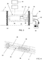
- Figure 3
- shows it in a schematic longitudinal section, and
- Figure 4
- shows a schematic perspective view a detail of the device according to the invention inserted inside the tubular shaft of the tent.
- As can be seen from the figures, the device according to the invention, generally designated by the
reference numeral 26, is applied/mounted, in the illustrated example, to a roll-up roof installation, in particular a roller blind, generally indicated with the number ofreference 1. - Preferably, the roller blind 1 is of the traditional type. Preferably, the roller blind 1 is motorized but could also be moved manually. In particular, the roller blind 1 is of the type with articulated arms, i.e. it is of the type that comprises a
tubular shaft 2, asupport structure 4 of thetubular shaft 2, asheet 6, which can be wound around thetubular shaft 2 and carried out by this, arigid crosspiece 8, to which the edge of thesheet 6 opposite to that constrained to thetubular shaft 2 is applied, and two pair of articulatedarms 10, which connect therigid crosspiece 8 to thesupport structure 4 and guide it in his translational movements with respect to thearms 10. - Conveniently, the winding/unwinding of the
sheet 6 can take place both along a substantially vertical direction, and along a more or less inclined direction with respect to the vertical. - The
tubular shaft 2 can be for example a metal shaft which, suitably, can have any cross-section. Preferably, thetubular shaft 2 can have a circular or polygonal section, for example hexagonal, octagonal or similar. Conveniently, thetubular shaft 2 is of the type traditionally usable for curtains and/or for rolling shutters. - Preferably, the
support structure 4 can comprise: - a rigid metal band, which appropriately adheres to a fixed structure, for example to the wall of a building,
- a first pair of
brackets 14 for fixing the rigid band to the fixed structure, and - a second pair of
brackets 16, 16', preferably shaped like wings, which extend from said rigid band towards the outside and which suitably support at the ends thetubular shaft 2 which is advantageously provided with all the necessary components for its proper functioning, as will be described further below. - Suitably, the
sheet 6 can be of any traditional type and does not require further explanation. - Conveniently, the
rigid crosspiece 8 can be constituted by a piece of metal or plastic profiled section and can have any section. Preferably, therigid crosspiece 8 is shaped so that when the tent is in a wound condition, it adheres to thesupport structure 4 and forms with it a sort of container or box, which houses inside it thetubular shaft 2, thesheet 6 wound on it and the articulatedarms 10, which are in the folded condition. - Advantageously, at least one acoustic diffuser 50 (i.e. an electro-acoustic transducer which transforms the electrical signal of an audio/sound amplifier into sound) is associated with the roller blind 1. Conveniently, the
acoustic diffuser 50 comprises at least one loudspeaker for reproducing different frequencies, preferably for the linear and precise reproduction of the whole audible frequency spectrum. - Preferably, the
acoustic diffuser 50 can be fixed and mounted directly on a rigid element of the roller blind 1, or it can be mounted on a further dedicated component which then in turn is associated with a component of the roller blind 1 or, again, can be mounted on the external fixed structure. Preferably, theacoustic diffuser 50 can be housed inside thetubular shaft 2 which, for this purpose, is provided with corresponding openings for sound diffusion. - Advantageously, as described in more detail below, the
acoustic diffuser 50 is connected - preferably by means of conductive wires for electrical connection - to thedevice 26 housed in thetubular shaft 2 at one end of said shaft which is opposite to the one in which the drive unit is inserted/housed or the means for actuation and manual actuation for the rotation of the shaft itself (as described in more detail below). Preferably, when theacoustic diffuser 50 is mounted on the roller blind 1, the conductive cables for electrical connection run, at least in part, inside the components of the curtain itself and, therefore, are hidden from view from the outside. - Advantageously,
lighting elements 18 can be mounted on the roller blind 1. Advantageously, thelighting elements 18 can be mounted on any component of the roller blind 1 and in any position thereof. More particularly, thelighting elements 18 can be mounted on thesupport structure 4 and/or on the articulatedarms 10 and/or on therigid crosspiece 8 and/or on thetubular shaft 2 and/or also on thesheet 6. Preferably, thelighting elements 18 are to be mounted on the rigid elements of the roller blind 1, such as thesupport structure 4 and/or the articulatedarms 10 and/or thetubular shaft 2 and/or therigid crosspiece 8 - Advantageously, as described in more detail in detail subsequently, the
lighting elements 18 are connected - preferably by means of cables/wires connecting to an electrical connection - to thedevice 26 housed in thetubular shaft 2. Preferably, the electrically connecting conductor cables run inside the components of the roller blind 1 and, therefore, they are hidden from view from the outside. - Advantageously, the
lighting elements 18 are light sources and, preferably, are strips of LEDs that define monochromatic and/or RGB light sources. - In particular, the
lighting elements 18 consist of at least one strip of LEDs which comprises a set of LED diodes, i.e. electronic components which emit light when supplied with electricity. Conveniently, the LED diodes are fixed - preferably by welding - on a printed circuit (PCB), preferably flexible, which performs the function of support and electrical connection. Advantageously, the LED diodes of the LED strip can be configured to emit monochromatic light or can be of the RGB type. - Advantageously, in the example shown in the figures, at the lower edge of the
support structure 4, at the lower edge of the articulatedarms 10 and at the lower edge of therigid crosspiece 8 are applied strips of led 18 which globally form diffuse sources of monochromatic light or light RGB and are connected to thedevice 26 housed in thetubular shaft 2 by means of electrical connection as conductor cables running inside therigid crosspiece 8 and the articulatedarms 10, and/or the other rigid components of theroller blind 1. - Suitably, the
roller blind 1 comprises means configured to cause rotation in the two directions of thetubular shaft 2, thus allowing to cover and unwind thecovering sheet 6 having a flap fixed to said shaft. - Advantageously, a drive unit is inserted in the
tubular shaft 2 to cause the shaft to rotate in both directions. Preferably, this drive unit is inserted inside thetubular shaft 2 at a first end thereof. Preferably, the unit comprises a traditional tubular driveelectric motor 20, preferably of the single-phase asynchronous type, inserted within the tubular shaft itself. Preferably, said unit also comprises means for the power supply of said electric motor and a control unit for controlling said motor. - More specifically, suitably, the
motor 20 is provided with amotor head 22 which is suitably fixed with any known system to thesupport structure 4, preferably it is fixed to thewing bracket 16 of the latter. Thetubular motor 20 is also provided with an output pinion to which an adapter 24 (pulley) for towing thetubular shaft 2 is coupled, cooperating in a traditional manner with a similarunattached adapter 24", which is mounted in the vicinity of saidhead 22. - Alternatively, means can be provided - which can be manually operated and actuated - configured to cause rotation in both directions of the
tubular shaft 2. Suitably, these means are configured to cause rotation in the two directions of thetubular shaft 2 can be constituted by a traditional winch that can be operated manually or with an electric motor applied thereto. - The
device 26 is also inserted inside thetubular shaft 2. Preferably, thisdevice 26 is inserted at the other end of thetubular shaft 2. - Preferably, at one end of the
tubular shaft 2 the drive unit of the shaft itself is inserted and housed while at the other end of thetubular shaft 2 thedevice 26 is inserted and housed. - Therefore, appropriately, the
device 26 is substantially independent and autonomous - both from a constructive point of view and positioning both from an operational operating point of view - with respect to the motorization unit of the roll-up roof installation. - Advantageously, the
device 26 comprises acasing 28, preferably tubular, which is removably inserted inside thetubular shaft 2. - Conveniently, the
device 26 comprises: - means 30 for fixing the
casing 28 to saidexternal support structure 4, and - means 24' which are interposed between said
casing 28 and thetubular shaft 2 and which are configured to allow thecasing 28 to support saidtubular shaft 2 in an idle manner, i.e. so as to decouple the rotation of thetubular shaft 2 from thecasing 28, thus allowing saidtubular shaft 2 to rotate about its longitudinal development axis while thecasing 28 remains fixed/stationary. - Conveniently, the means for fixing the
casing 28 to saidexternal support structure 4 comprise ahead 30 which is applied to thecasing 28 so as to fix it to theexternal support structure 4. In particular, thehead 30 makes thecasing 28 to theexternal support structure 4, thus supporting thetubular shaft 2 at one of its ends. - Preferably, the fixing
head 30 that allows fixing to the other wing bracket 16' of thesupport structure 4, is appropriately applied to the casing 28 (in particular on its outer side) and a pair of adapters 24'. - Advantageously, said means which are interposed between said
casing 28 and thetubular shaft 2 comprise at least one adapter 24' which is interposed between thecasing 28 and thetubular shaft 2 and which is configured to rotate with saidtubular shaft 2 and to allow thecasing 28 to idly support thetubular shaft 2. Advantageously, between thecasing 28 and thetubular shaft 2 there are interposed the adapters 24' supporting thecasing 28 inside the same shaft. Preferably, a pair of support adapters 24' is provided, interposed between the opposite sides of thecasing 28 and thetubular shaft 2. - Preferably, both the
head 30 and the adapters 24' have a shape similar to that of thehead 22 and of theadapters 24 of thetubular motor 20, but unlike those having the sole function of idle support of thetubular shaft 2 at its opposite end to that for inserting saidmotor 20. - Suitably, it is understood that the shape and dimensions of the
casing 28 are not connected to those of thetubular shaft 2 although obviously they must be compatible with those. In particular, thecasing 28 has a shape and dimensions suitable for allowing its insertion and housing inside thetubular shaft 2. Suitably, the stability of the positioning of thecasing 28 inside thetubular shaft 2 is obtained by means of the adapters 24'. - Suitably, the
device 26 according to the invention comprises: - at least one
amplifier 51 intended to be connected with theacoustic diffuser 50 and configured to amplify the audio signals received at the input and for outputting the audio signals thus amplified to said at least oneacoustic diffuser 50, - at least one
receiver 36 which is connected to saidamplifier 51 and that is configured to receive from the outside the audio signals to be amplified by means of said at least oneamplifier 51, - a unit for the control and
command 35 of the reproduction of the audio signals received from the outside by saidreceiver 36, - a
power supply 34 for supplying electrical energy to said control andcommand unit 35, to saidreceiver 36 and to saidamplifier 51. - Advantageously, the
receiver 36 is connected or incorporated in saidcontrol unit 35. Advantageously, theamplifier 51 it is connected or incorporated in saidcontrol unit 35. Advantageously, thecontrol unit 35 comprises a processor. Preferably, thecontrol unit 35 comprises a microcontroller. - Advantageously, the
control unit 35 is connected with anoutput interface 40 provided outside thetubular body 28 and in turn connected to thelighting elements 18. Conveniently, the connection between the control unit 35 (housed in the the interior of thecasing 28, and therefore inside the tubular shaft 2) and the output interface 40 (positioned outside the tubular shaft 2), as well as between the latter and thelighting elements 18 is obtained by means of conductor cables for connection and transmission of electrical signals. Preferably, the command/communication drivers with theoutput interface 40 connected to thelighting elements 18 are implemented in thecontrol unit 35. - Suitably, the
amplifier 51 is of the traditional type and is configured to amplify the audio signals received in input and thus supply in output amplified audio signals to be sent to theacoustic diffuser 50 mounted outside thecasing 28 and thetubular shaft 2. Advantageously, theamplifier 51 comprises suitable electronic components for the amplification of audio signals. Conveniently, theamplifier 51 is configured and intended to amplify only the audio signals to be sent to anacoustic diffuser 50 for the corresponding sound reproduction, and in particular it is not provided for amplifying command and/or control signals. Preferably, theamplifier 51 comprises an electronic circuit configured for the amplification of the audio signals at the input and, suitably, this amplifier is connected or incorporated in thecontrol unit 35. - Advantageously, inside the
casing 28 is housed thepower supply 34 for thelighting elements 18 and for thecontrol unit 35. - Advantageously, the
amplifier 51 provided inside thecasing 28 is connected with theacoustic diffuser 50 provided outside thecasing 28 and of the tubular shaft. Conveniently, the connection between the amplifier 51 (housed inside thecasing 28, and therefore inside the tubular shaft 2) and the acoustic diffuser 50 (positioned outside the tubular shaft 2) is obtained by means of conductor cables for the connection and transmission of audio signals. - Preferably, inside the
casing 28 there is also provided thereceiver 36 which is connected, via wireless (for example via Bluetooth or Wi-Fi) and/or via wire, with at least one source apparatus provided outside of saidroller blind 1 so as to receive, from said external source apparatus, the audio signals to be amplified by theamplifier 51 and then send them to theacoustic diffuser 50 to convert them into sounds. - Advantageously, the
receiver 36 is of the wireless type, preferably radio. Preferably, thereceiver 36 is a Bluetooth receiver. - Preferably, an antenna is connected to the
receiver 36 to enhance the signal sent wirelessly from the external source device. - Advantageously, the
receiver 36 is also configured to receive transmitted audio signals from radio stations (both in FM and in AM, as well as in digital format). - Advantageously, the
receiver 36 can be configured to receive via audio the audio signals to be amplified, preferably by means of a USB interface or other known interfaces suitable for the transmission of audio signals. - Advantageously, the
receiver 36 can be configured to receive the audio signals to be amplified wirelessly, preferably by radio (for example by means of the Bluetooth standard), and also to receive said audio signals via wire (for example by means of a USB interface). - Conveniently, by means of the
receiver 36 thecontrol unit 35 can receive audio signals from an external source apparatus which acts as a transmitter, and in particular from a remote control or even from a cellular telephone (preferably a smartphone) or tablet, or from other traditional wireless devices in general. Conveniently, for this purpose, thereceiver 36 is connected and/or incorporated to the electronic circuit of thecontrol unit 35 to be operatively connected to theamplifier 51 connected to thediffuser 50. - Preferably, inside the
casing 28 is also provided thereceiver 36 which is connected, via wireless (for example via Bluetooth or Wi-Fi) and/or by wire, with the outside of saidroller blind 1 to receive from the outside also the control signals to control, based on these, thelighting elements 18. - Conveniently, by means of the
receiver 36 thecontrol unit 35 can receive from an external transmitter, and in particular from a remote control or even from a cellular phone, preferably a smartphone, or from other traditional wireless devices in general, control signals for thelighting elements 18. Conveniently, for this purpose, thereceiver 36 is connected and/or incorporated to the electronic circuit of thecontrol unit 35 for be operatively connected with the control/communication drivers of theoutput interface 40 connected to thelighting elements 18. - Advantageously, the
receiver 36 can also be connected via radio to light, wind, rain and/or snow sensors. - Conveniently, therefore, the
device 26 comprises at least one receiver 36 - preferably a single receiver - configured to receive from the outside both the audio signals to be amplified by means of said at least oneamplifier 51, and the control signals to control the switching on and off. and the adjustment of thelighting elements 18 and/or of the sound reproduction to be carried out by theacoustic diffuser 50. However, only the audio signals thus received are sent to theamplifier 51, while the received command signals are not sent to theamplifier 51 and - in particular - they are not amplified in any way. - The
receiver 36 can advantageously be replaced by a transceiver, preferably radio, which in addition to sending the audio signals to theamplifier 51 or corresponding control signals to thelighting elements 18 and/or to theamplifier 51 and/or to theacoustic diffuser 50, it can remotely communicate the status of the elements themselves and, preferably, also the operating parameters or the possible presence of anomalies or malfunctions. In particular, for this purpose, the transceiver, in addition to controlling and communicating - with its receiver side - with theamplifier 51, connected with theacoustic diffuser 50, and with theoutput interface 40 connected to thelighting elements 18, can transmit with the transmitter side signals on the state of theacoustic diffuser 50 and/or of thelighting elements 18 themselves. Basically, appropriately, in this way the user can remotely control, for example by means of a mobile phone (preferably by smartphone) or a tablet, the switching on, switching off and adjustment of the sound reproduction and/or of thelighting elements 18 and can receive, again with the mobile phone (preferably a smartphone), information on the current status of these. Conveniently, the transceiver is connected and/or incorporated to the electronic circuit of thecontrol unit 35 to be operatively connected to theamplifier 51 and/or to the control/communication drivers of theoutput interface 40 connected to thelighting elements 18. - Advantageously, the receiver 36 - in its transceiver version - can be configured to receive audio signals to be amplified and also for retransmitting by radio said audio signals, once they have been amplified by said at least one
amplifier 51, to other installations or units for the audio reproduction which are arranged to receive said signals and which are positioned, within an appropriate radius of coverage, at a greater distance. - Advantageously, in the case of an external portable device such as a smartphone or tablet, a software module - which preferably consists of a native mobile software application, also known as APP - configured to connect wirelessly with the
receiver 36 for the management and setting of the connections of thecontrol unit 35 with the external control devices, as well as for controlling the switching on, switching off and adjustment of the sound reproduction by means of thediffuser 50 and/or thelighting elements 18. - Advantageously, according to a further embodiment, the
receiver 36 can be connected to a centralized or distributed home automation unit which is configured to receive information from thereceiver 36, and send it, preferably via Wi-Fi and through Internet protocols, to the external portable apparatus and/or to a cloud archive accessible from the external portable device, so as to feeling the remote control of thedevice 26, in addition to monitoring its operation. Conveniently, the connection between thereceiver 36 and the home automation unit can take place via cable or wireless, in particular by radio waves (for example Wi-Fi or according to the Bluetooth protocol). - Advantageously, the
power supply 34 housed in thecasing 28 can be supplied from the outside, preferably it is fed directly through acable 38 connected to an external electric source (preferably to the mains) and therefore in practice without any limitation on the power that can be delivered and therefore on the quantity/number oflighting elements 18 can be supplied. - It is also envisaged that, alternatively, the
power supply 34 housed in thecasing 28 may be powered by one ormore batteries 42 which, preferably, may be recharged with one or more externalphotovoltaic panels 44 which, suitably, may be mounted on thecover installation 1 and/or may be external and independent from the latter. - The
rechargeable battery 42 can advantageously be housed inside thecasing 28. - Advantageously, on the side wall of the
casing 28 it is provided afirst door 46 for accessing to the inside of the casing itself from the outside, for example to be able to access to the rechargeable battery 42 - if provided. Advantageously, asecond door 48 may also be provided in thetubular shaft 2 to access thefirst door 46 formed in thecasing 28. Conveniently, it is understood that thefirst door 46 of thecasing 28 and the thesecond door 48 of thetubular shaft 2 faces each other. Obviously, in the example illustrated in the figures, this accessibility requires that thedevice 26 is correctly inserted into thetubular shaft 2 and that the curtain is unfolded, i.e. that thesheet 6 is unwound from thetubular shaft 2 and does not cover thesecond door 48. - Advantageously, the same
rechargeable battery 42 can also supply themotor 20, preferably through an inverter, also housed inside thecasing 28. Suitably, in this case, theentire curtain 1 can also be installed in place where power supply is not available. Advantageously, it is in any case provided that themotor 20 can be supplied through an external low voltage supply, again by means of an inverter. - From the aforegoing it is apparent that the device according to the invention is advantageous and in particular:
- enables the amplification section of an audio reproduction system to be integrated in an efficient and space-saving way in the roof installation,
- thanks to its integration in the
casing 28 makes its installation simple and rapid, since it requires only the insertion of thecasing 28 inside thetubular shaft 2, the constraint of the shaft thus equipped to thesupport structure 4 and the connection of thedevice 26 to the acoustic diffuser and/or to the lighting sources and, if provided, to the external mains supply, - It defines an element of mechanical connection between the
tubular shaft 2 and the fixedsupport structure 4, - it practically does not imply any limitation in the electric power that can be supplied and therefore it is able to feed and also control a large number of loudspeakers and/or lighting elements,
- if it uses
photovoltaic panels 44 it makes the device and more generally the entire tent independent from the external electric network, - it allows the
rechargeable battery 42 to be housed inside thecasing 28, further simplifying the installation of the device and eliminating in particular the external fixed batteries. - The device according to the present invention has been described herein in particular with reference to its application in a
roller blind 1, however it is intended that it can be applied in any installation of roll-up cover, both vertical and inclined, such as for example shutters, shutters or also a sectional door. - In particular, unlike the solution envisaged in
US2018/355662 , in the device according to the present invention the amplifier is an amplifier of audio signals and, in particular, amplifies the audio signals which are received from the outside through the receiver of which the device itself is provided. On the contrary, inUS2018/355662 no audio signal amplifier is provided since at most the activation signal/command to be sent to the acoustic speaker is amplified; moreover,US2018/355662 does not provide for the audio signals to be amplified to be received by the receiver provided in the device. Not least is the fact that inUS2018/355662 no receiver is provided which is housed inside the same casing as the processor defining the unit of control and command.
Claims (15)
- Device (26) to be mounted on a roll-up cover installation (1), said roll-up cover installation (1) being of the type comprising:- a support structure (4) for the constraint of said cover installation (1) to a fixed external structure,- a tubular shaft (2) supported by said structure (4),- means configured to cause the rotation of said tubular shaft (2),- a sheet (6) to be wound on said tubular shaft (2) and to be unwound from this,characterized in that it comprises a casing (28) which can be removably inserted and housed in said tubular shaft (2) at an opposite end compared to that in which are housed said means configured for causing the rotation of said tubular shaft (2), inside said casing (28) being arranged and accommodated:- at least one amplifier (51) intended to be connected with said at least one acoustic diffuser (50) and configured to amplify the audio signals received at the input and for outputting the audio signals thus amplified to said at least one acoustic diffuser (50),- at least one receiver or transceiver (36) which is connected to said amplifier (51) and which is configured to receive from the outside the audio signals to be amplified by means of said at least one amplifier (51).- a unit for the control and command (35) of the reproduction of the audio signals received by said receiver or transceiver (36), said amplifier (51) and said receiver/transceiver (36) being connected and/or incorporated in said control and command unit (35),- at least one power supply (34) for supplying electrical energy to said control and command unit (35), to said receiver/transceiver (36) and to said amplifier (51).
- Device according to claim 1, characterized in that it comprises at least one conductor cable for connecting and transmitting audio signals, said at least one cable being connected to said amplifier (51), which is housed inside the casing (28), and exits from said casing (28) to be connected with said at least one acoustic diffuser (50) which is intended to be positioned outside the tubular shaft (2).
- Device according to one or more of the preceding claims, characterized in that:- said control and command unit (35) can be connected via wireless and/or wire with a plurality of lighting elements (18) applied to at least one component (2,4,6,8,10) of said roll-up cover installation (1),- said at least one power supply (34) is also configured to provide electricity to said lighting elements (18),- said receiver or transceiver (36) is connected and/or incorporated in said control and command unit (35) to receive control signals from the outside to control, based on these, said lighting elements (18).
- Device according to one or more of the preceding claims, characterized in that it comprises:- means (30) for securing said casing (28) to said outer support structure (4),- means (24') interposed between said casing (28) and said tubular shaft (2) and configured to allow said casing (28) to support said tubular shaft (2) so that said tubular shaft (2) rotates around the its axis while said casing (28) remains fixed.
- Device according to one or more of the preceding claims, characterized in that it comprises:- a head (30) which is applied to the outer side of the casing (28) to fix it to the external support structure (4), and/or- at least one adapter (24') which is interposed between said casing (28) and the tubular shaft (2) and which is configured to rotate with said tubular shaft (2) and to allow the casing (28) to support in an idle way the tubular shaft (2).
- Device according to one or more of the preceding claims, characterized in that said power supply (34) housed in the casing (28) is fed from the outside through a cable (38) which comes out from said casing (28) to be connected to a external electrical source.
- Device according to one or more of the preceding claims, characterized in that it comprises at least one rechargeable battery (42) for supplying the device itself, said battery being connected to said power supply (34), which is housed inside said casing (28) and is accessible from the outside by means of doors (46, 48) formed in the casing (28) and in the tubular shaft (2) respectively.
- Device according to one or more of the preceding claims, characterized in that said receiver (36) is configured to receive via cable the audio signals to be amplified, preferably by means of a USB interface or other interfaces suitable for transmitting audio signals.
- Device according to one or more of the preceding claims, characterized in that inside the casing (28) a receiver or transceiver (36) is housed which is of the wireless type and is arranged to communicate wirelessly with an external terminal, in particular with a portable device, to receive the audio signals to be amplified sent by said external terminal.
- Device according to one or more of the preceding claims, characterized in that inside the casing (28) it is housed a receiver or transceiver (36) which is of the wireless type and is configured to receive audio signals transmitted by radio stations.
- Device according to one or more of the preceding claims, characterized in that inside the casing (28) is housed at least one receiver or a transceiver which is of the wireless type and is arranged to communicate wirelessly with an external terminal, in particular with a portable apparatus, for receiving control signals, sent from said external terminal, to control the switching on and off and adjustment of the lighting elements (18) and/or the sound reproduction to be carried out by means of the acoustic diffuser (50).
- Installation of a roll-up cover (1) characterized in that it comprises a device (26) according to one or more of the preceding claims, and also characterized in that said device (26) is inserted and housed inside the tubular shaft (2) of said installation at one end of said shaft which is opposite to the end where the means for moving said shaft (2) are housed.
- Installation according to the previous claim, characterized in that it comprises an acoustic diffuser (50) which is positioned outside said tubular shaft (2) and which is electrically connected to said at least one amplifier (51) by at least one conductor cable connecting and transmitting audio signals coming out of the casing (28) of said device (26).
- Installation according to the previous claim, characterized in that it comprises lighting elements (18) which are mounted on at least one component of said installation (1) and which are electrically connected to said control unit (35) of said device (26).
- Installation of a roll-up cover (1) characterized in that it comprises:- a support structure (4) for the constraint of said cover installation (1) to a fixed external structure,- a tubular shaft (2) supported by said structure (4),- a motorization unit (20) to cause the rotation of said tubular shaft (2), said motorization unit (20) is inserted and housed inside the tubular shaft (2) of said installation at one end of said shaft (2),- a cover (6) to be wrapped on said tubular shaft (2) and to be carried by this,- a supporting structure (8, 10) of said sheet (6),and in that the casing (28) of said device (26) is housed inside said tubular shaft (2), between the latter and the support structure (4), and is provided with means (24', 30) which are configured to allow the casing (28) to idly support said tubular shaft (2).
Applications Claiming Priority (1)
| Application Number | Priority Date | Filing Date | Title |
|---|---|---|---|
| IT102018000020503A IT201800020503A1 (en) | 2018-12-20 | 2018-12-20 | DEVICE TO BE MOUNTED ON A ROLLING COVER INSTALLATION |
Publications (2)
| Publication Number | Publication Date |
|---|---|
| EP3671377A1 true EP3671377A1 (en) | 2020-06-24 |
| EP3671377B1 EP3671377B1 (en) | 2023-08-30 |
Family
ID=65951973
Family Applications (1)
| Application Number | Title | Priority Date | Filing Date |
|---|---|---|---|
| EP19216958.9A Active EP3671377B1 (en) | 2018-12-20 | 2019-12-17 | Device to be mounted on a covering installation |
Country Status (3)
| Country | Link |
|---|---|
| EP (1) | EP3671377B1 (en) |
| ES (1) | ES2964375T3 (en) |
| IT (1) | IT201800020503A1 (en) |
Cited By (2)
| Publication number | Priority date | Publication date | Assignee | Title |
|---|---|---|---|---|
| EP4095344A1 (en) * | 2021-05-25 | 2022-11-30 | Teleco Automation S.R.L. | Control device for lighting elements to be mounted on a roll-up cover installation |
| CN116411685A (en) * | 2023-04-07 | 2023-07-11 | 浙江湖州森富机电有限责任公司 | Ceiling awning curtain motor control system |
Citations (9)
| Publication number | Priority date | Publication date | Assignee | Title |
|---|---|---|---|---|
| EP2395176A2 (en) * | 2010-06-09 | 2011-12-14 | Schmitz-Werke GmbH + Co. KG | Awning |
| US20120031571A1 (en) * | 2010-02-23 | 2012-02-09 | Homerun Holdings Corporation | High Efficiency Roller Shade |
| US20140000819A1 (en) * | 2012-07-02 | 2014-01-02 | Homerun Holdings Corporation | Pre-assembled and pre-tensioned shade with indexing gear tensioner |
| AU2014200269A1 (en) | 2010-02-23 | 2014-01-30 | The Watt Stopper, Inc. | High efficiency roller shade |
| US20150362896A1 (en) | 2014-06-17 | 2015-12-17 | Crestron Electronics, Inc. | Shading Control Network Using a Control Network |
| US20170101820A1 (en) | 2015-10-12 | 2017-04-13 | Crestron Electronics, Inc. | Touch hem bar control |
| US20170191273A1 (en) * | 2016-01-05 | 2017-07-06 | Sunsetter Products Limited Partnership | Solar battery powered awning |
| US20180355662A1 (en) | 2017-06-13 | 2018-12-13 | David R. Hall | Weather Influenced Window Shade Alarm Clock |
| EP3450672A1 (en) * | 2017-08-30 | 2019-03-06 | WAREMA Renkhoff SE | Sun protection facility with an awning cloth |
-
2018
- 2018-12-20 IT IT102018000020503A patent/IT201800020503A1/en unknown
-
2019
- 2019-12-17 ES ES19216958T patent/ES2964375T3/en active Active
- 2019-12-17 EP EP19216958.9A patent/EP3671377B1/en active Active
Patent Citations (9)
| Publication number | Priority date | Publication date | Assignee | Title |
|---|---|---|---|---|
| US20120031571A1 (en) * | 2010-02-23 | 2012-02-09 | Homerun Holdings Corporation | High Efficiency Roller Shade |
| AU2014200269A1 (en) | 2010-02-23 | 2014-01-30 | The Watt Stopper, Inc. | High efficiency roller shade |
| EP2395176A2 (en) * | 2010-06-09 | 2011-12-14 | Schmitz-Werke GmbH + Co. KG | Awning |
| US20140000819A1 (en) * | 2012-07-02 | 2014-01-02 | Homerun Holdings Corporation | Pre-assembled and pre-tensioned shade with indexing gear tensioner |
| US20150362896A1 (en) | 2014-06-17 | 2015-12-17 | Crestron Electronics, Inc. | Shading Control Network Using a Control Network |
| US20170101820A1 (en) | 2015-10-12 | 2017-04-13 | Crestron Electronics, Inc. | Touch hem bar control |
| US20170191273A1 (en) * | 2016-01-05 | 2017-07-06 | Sunsetter Products Limited Partnership | Solar battery powered awning |
| US20180355662A1 (en) | 2017-06-13 | 2018-12-13 | David R. Hall | Weather Influenced Window Shade Alarm Clock |
| EP3450672A1 (en) * | 2017-08-30 | 2019-03-06 | WAREMA Renkhoff SE | Sun protection facility with an awning cloth |
Cited By (3)
| Publication number | Priority date | Publication date | Assignee | Title |
|---|---|---|---|---|
| EP4095344A1 (en) * | 2021-05-25 | 2022-11-30 | Teleco Automation S.R.L. | Control device for lighting elements to be mounted on a roll-up cover installation |
| CN116411685A (en) * | 2023-04-07 | 2023-07-11 | 浙江湖州森富机电有限责任公司 | Ceiling awning curtain motor control system |
| CN116411685B (en) * | 2023-04-07 | 2023-08-29 | 浙江湖州森富机电有限责任公司 | Ceiling awning curtain motor control system |
Also Published As
| Publication number | Publication date |
|---|---|
| IT201800020503A1 (en) | 2020-06-20 |
| ES2964375T3 (en) | 2024-04-05 |
| EP3671377B1 (en) | 2023-08-30 |
Similar Documents
| Publication | Publication Date | Title |
|---|---|---|
| EP3671377B1 (en) | Device to be mounted on a covering installation | |
| JP4532901B2 (en) | Operator system and opening member including the operator system | |
| US11739533B2 (en) | Control device for the lighting elements to be mounted on a roller covering installation | |
| NL2020715B1 (en) | Electrically-driven window shade and its actuating mechanism | |
| AU2011220886B2 (en) | High efficiency roller shade | |
| AU2011318560B2 (en) | Motorizable shade system and method | |
| CA2987858C (en) | Method for operating a motorized roller shade | |
| JP6194370B2 (en) | Electric blinds | |
| US20140133019A1 (en) | High efficiency motorized roller screen and method of operation | |
| JP2009516097A (en) | Sunshade control unit | |
| JP2011256701A (en) | Awning | |
| EP1595056B1 (en) | Winding device | |
| AU2014200269B2 (en) | High efficiency roller shade | |
| EP3670780B1 (en) | A device for controlling a roll-up cover installation | |
| CN215015987U (en) | Intelligent curtain device of free installation | |
| EP4095344A1 (en) | Control device for lighting elements to be mounted on a roll-up cover installation | |
| CN101077243B (en) | Multifunction umbrella | |
| AU2016202932A1 (en) | High efficiency roller shade | |
| EP3480416B1 (en) | Apparatus for the movement and control of a rolling shutter | |
| US20220251901A1 (en) | Roller tube for driving color-changing shade | |
| KR20020085339A (en) | Roller Screen Motorized System |
Legal Events
| Date | Code | Title | Description |
|---|---|---|---|
| PUAI | Public reference made under article 153(3) epc to a published international application that has entered the european phase |
Free format text: ORIGINAL CODE: 0009012 |
|
| STAA | Information on the status of an ep patent application or granted ep patent |
Free format text: STATUS: THE APPLICATION HAS BEEN PUBLISHED |
|
| AK | Designated contracting states |
Kind code of ref document: A1 Designated state(s): AL AT BE BG CH CY CZ DE DK EE ES FI FR GB GR HR HU IE IS IT LI LT LU LV MC MK MT NL NO PL PT RO RS SE SI SK SM TR |
|
| AX | Request for extension of the european patent |
Extension state: BA ME |
|
| STAA | Information on the status of an ep patent application or granted ep patent |
Free format text: STATUS: REQUEST FOR EXAMINATION WAS MADE |
|
| 17P | Request for examination filed |
Effective date: 20201221 |
|
| RBV | Designated contracting states (corrected) |
Designated state(s): AL AT BE BG CH CY CZ DE DK EE ES FI FR GB GR HR HU IE IS IT LI LT LU LV MC MK MT NL NO PL PT RO RS SE SI SK SM TR |
|
| STAA | Information on the status of an ep patent application or granted ep patent |
Free format text: STATUS: EXAMINATION IS IN PROGRESS |
|
| 17Q | First examination report despatched |
Effective date: 20211007 |
|
| GRAP | Despatch of communication of intention to grant a patent |
Free format text: ORIGINAL CODE: EPIDOSNIGR1 |
|
| STAA | Information on the status of an ep patent application or granted ep patent |
Free format text: STATUS: GRANT OF PATENT IS INTENDED |
|
| RIC1 | Information provided on ipc code assigned before grant |
Ipc: G05B 15/02 20060101AFI20230227BHEP |
|
| INTG | Intention to grant announced |
Effective date: 20230328 |
|
| GRAS | Grant fee paid |
Free format text: ORIGINAL CODE: EPIDOSNIGR3 |
|
| GRAA | (expected) grant |
Free format text: ORIGINAL CODE: 0009210 |
|
| STAA | Information on the status of an ep patent application or granted ep patent |
Free format text: STATUS: THE PATENT HAS BEEN GRANTED |
|
| AK | Designated contracting states |
Kind code of ref document: B1 Designated state(s): AL AT BE BG CH CY CZ DE DK EE ES FI FR GB GR HR HU IE IS IT LI LT LU LV MC MK MT NL NO PL PT RO RS SE SI SK SM TR |
|
| REG | Reference to a national code |
Ref country code: GB Ref legal event code: FG4D |
|
| REG | Reference to a national code |
Ref country code: CH Ref legal event code: EP |
|
| REG | Reference to a national code |
Ref country code: DE Ref legal event code: R096 Ref document number: 602019036054 Country of ref document: DE |
|
| REG | Reference to a national code |
Ref country code: IE Ref legal event code: FG4D |
|
| REG | Reference to a national code |
Ref country code: NL Ref legal event code: FP |
|
| REG | Reference to a national code |
Ref country code: LT Ref legal event code: MG9D |
|
| REG | Reference to a national code |
Ref country code: AT Ref legal event code: MK05 Ref document number: 1606229 Country of ref document: AT Kind code of ref document: T Effective date: 20230830 |
|
| PGFP | Annual fee paid to national office [announced via postgrant information from national office to epo] |
Ref country code: GR Payment date: 20231219 Year of fee payment: 5 |
|
| PG25 | Lapsed in a contracting state [announced via postgrant information from national office to epo] |
Ref country code: IS Free format text: LAPSE BECAUSE OF FAILURE TO SUBMIT A TRANSLATION OF THE DESCRIPTION OR TO PAY THE FEE WITHIN THE PRESCRIBED TIME-LIMIT Effective date: 20231230 |
|
| REG | Reference to a national code |
Ref country code: GR Ref legal event code: EP Ref document number: 20230402268 Country of ref document: GR Effective date: 20240110 |
|
| PG25 | Lapsed in a contracting state [announced via postgrant information from national office to epo] |
Ref country code: SE Free format text: LAPSE BECAUSE OF FAILURE TO SUBMIT A TRANSLATION OF THE DESCRIPTION OR TO PAY THE FEE WITHIN THE PRESCRIBED TIME-LIMIT Effective date: 20230830 Ref country code: RS Free format text: LAPSE BECAUSE OF FAILURE TO SUBMIT A TRANSLATION OF THE DESCRIPTION OR TO PAY THE FEE WITHIN THE PRESCRIBED TIME-LIMIT Effective date: 20230830 Ref country code: NO Free format text: LAPSE BECAUSE OF FAILURE TO SUBMIT A TRANSLATION OF THE DESCRIPTION OR TO PAY THE FEE WITHIN THE PRESCRIBED TIME-LIMIT Effective date: 20231130 Ref country code: LV Free format text: LAPSE BECAUSE OF FAILURE TO SUBMIT A TRANSLATION OF THE DESCRIPTION OR TO PAY THE FEE WITHIN THE PRESCRIBED TIME-LIMIT Effective date: 20230830 Ref country code: LT Free format text: LAPSE BECAUSE OF FAILURE TO SUBMIT A TRANSLATION OF THE DESCRIPTION OR TO PAY THE FEE WITHIN THE PRESCRIBED TIME-LIMIT Effective date: 20230830 Ref country code: IS Free format text: LAPSE BECAUSE OF FAILURE TO SUBMIT A TRANSLATION OF THE DESCRIPTION OR TO PAY THE FEE WITHIN THE PRESCRIBED TIME-LIMIT Effective date: 20231230 Ref country code: HR Free format text: LAPSE BECAUSE OF FAILURE TO SUBMIT A TRANSLATION OF THE DESCRIPTION OR TO PAY THE FEE WITHIN THE PRESCRIBED TIME-LIMIT Effective date: 20230830 Ref country code: FI Free format text: LAPSE BECAUSE OF FAILURE TO SUBMIT A TRANSLATION OF THE DESCRIPTION OR TO PAY THE FEE WITHIN THE PRESCRIBED TIME-LIMIT Effective date: 20230830 Ref country code: AT Free format text: LAPSE BECAUSE OF FAILURE TO SUBMIT A TRANSLATION OF THE DESCRIPTION OR TO PAY THE FEE WITHIN THE PRESCRIBED TIME-LIMIT Effective date: 20230830 |
|
| PGFP | Annual fee paid to national office [announced via postgrant information from national office to epo] |
Ref country code: TR Payment date: 20231213 Year of fee payment: 5 Ref country code: FR Payment date: 20231219 Year of fee payment: 5 |
|
| PG25 | Lapsed in a contracting state [announced via postgrant information from national office to epo] |
Ref country code: PL Free format text: LAPSE BECAUSE OF FAILURE TO SUBMIT A TRANSLATION OF THE DESCRIPTION OR TO PAY THE FEE WITHIN THE PRESCRIBED TIME-LIMIT Effective date: 20230830 |
|
| PGFP | Annual fee paid to national office [announced via postgrant information from national office to epo] |
Ref country code: NL Payment date: 20231228 Year of fee payment: 5 Ref country code: BE Payment date: 20231228 Year of fee payment: 5 |
|
| REG | Reference to a national code |
Ref country code: ES Ref legal event code: FG2A Ref document number: 2964375 Country of ref document: ES Kind code of ref document: T3 Effective date: 20240405 |
|
| PGFP | Annual fee paid to national office [announced via postgrant information from national office to epo] |
Ref country code: ES Payment date: 20240116 Year of fee payment: 5 |