EP3671360A1 - Winder with bumper system - Google Patents
Winder with bumper system Download PDFInfo
- Publication number
- EP3671360A1 EP3671360A1 EP19217712.9A EP19217712A EP3671360A1 EP 3671360 A1 EP3671360 A1 EP 3671360A1 EP 19217712 A EP19217712 A EP 19217712A EP 3671360 A1 EP3671360 A1 EP 3671360A1
- Authority
- EP
- European Patent Office
- Prior art keywords
- watch
- rod
- base
- leaf spring
- crown
- Prior art date
- Legal status (The legal status is an assumption and is not a legal conclusion. Google has not performed a legal analysis and makes no representation as to the accuracy of the status listed.)
- Pending
Links
Images


Classifications
-
- G—PHYSICS
- G04—HOROLOGY
- G04B—MECHANICALLY-DRIVEN CLOCKS OR WATCHES; MECHANICAL PARTS OF CLOCKS OR WATCHES IN GENERAL; TIME PIECES USING THE POSITION OF THE SUN, MOON OR STARS
- G04B27/00—Mechanical devices for setting the time indicating means
- G04B27/02—Mechanical devices for setting the time indicating means by making use of the winding means
- G04B27/04—Mechanical devices for setting the time indicating means by making use of the winding means with clutch wheel
-
- G—PHYSICS
- G04—HOROLOGY
- G04B—MECHANICALLY-DRIVEN CLOCKS OR WATCHES; MECHANICAL PARTS OF CLOCKS OR WATCHES IN GENERAL; TIME PIECES USING THE POSITION OF THE SUN, MOON OR STARS
- G04B3/00—Normal winding of clockworks by hand or mechanically; Winding up several mainsprings or driving weights simultaneously
- G04B3/04—Rigidly-mounted keys, knobs or crowns
- G04B3/046—Operation by rotation and axial movement with extra function of axial shift of operating element, e.g. crown combined with push button
-
- G—PHYSICS
- G04—HOROLOGY
- G04B—MECHANICALLY-DRIVEN CLOCKS OR WATCHES; MECHANICAL PARTS OF CLOCKS OR WATCHES IN GENERAL; TIME PIECES USING THE POSITION OF THE SUN, MOON OR STARS
- G04B43/00—Protecting clockworks by shields or other means against external influences, e.g. magnetic fields
- G04B43/002—Component shock protection arrangements
Definitions
- the present invention relates generally to a watch mechanism with an adjustment or control device, such as a winding crown or a push-piece.
- the document EP1564607B1 describes a timepiece movement with a crown and a cover to protect the crown and the associated winding stem.
- this system has the particular disadvantage of being bulky, of extending outwardly to the middle part and of requiring intervention by the user of the watch to unmask the crown in order to use it.
- An object of the present invention is to respond to the drawbacks of the document of the prior art mentioned above and in particular, first of all, to propose a watch and a watch mechanism making it possible, in addition to an aesthetic improvement, to protect the adjustment or control devices, such as crowns or pushers, and the elements cooperating with them, to avoid an unexpected engagement or deterioration in the event of impacts.
- the present invention also makes it possible to reduce the size of the watch and not to require an intervention by the wearer of the watch to unmask the adjustment or control devices.
- base a part of a part serving as support or support.
- the rod is arranged to cooperate with said adjustment or control means, that is to say that the rod is integral with the adjustment or control means at least in rotation or in translation, so as to allow adjustment or watch function control, such as winding a power reserve barrel, setting the hours, minutes, seconds, setting the dates or days, setting the moon phase, setting the ring, setting the '' a chronograph or stopwatch, control of a balance or tourbillon stop or adjustment device, control of a decorative function or indication of the time on demand, or any other similar or similar function .
- the elastic element protects the part on which it is fixed or in support of a shock from the rod.
- the elastic element is a return spring blade, arranged to exert an axial force on the rod.
- the clockwork mechanism for a watch further comprises a control member, such as a sliding pinion, cooperating with the adjustment or control means, and in which the elastic element is arranged between the control member and the base.
- a control member such as a sliding pinion
- the spring blade or return spring blade is arranged at a safe distance from the base.
- the leaf spring is mounted in tension, so as to exert a restoring force greater than a predetermined threshold, and to prevent the rod from traveling the safety distance in the event of a shock of small magnitude.
- the safety distance is less than a distance separating the crown from the base, in an axial direction of the rod.
- intersecting is meant the fact that the flat surface of the base has an intersection with the longitudinal axis of the rod, apart from a leave formed in the flat surface of the base so as to receive one end of the rod.
- the leaf spring is arranged in abutment at two surfaces against the base so as to form a beam, aiming to obstruct the rod at a cantilever and to exert an axial restoring force. on the rod in the event of an impact, by modifying a lever arm.
- the leaf spring comprises a flat surface arranged opposite the bearing portion of the rod, so as to form a stop.
- the leaf spring is positioned very precisely. It is alternatively possible to provide a form of fork for threading the leaf spring on the rod, so as to facilitate assembly.
- the flat surface of the base includes a leave arranged to receive the guide end.
- the mechanism further comprises a stop piece on the side of the crown, and in which the spring leaf is arranged between the base and the stop piece, and arranged in tension against the stop piece, so as to form a another stop.
- the mechanism further comprises a stop piece, and in which the leaf spring is arranged between the base and the stop piece, so as to form a third stop.
- the abutment part on the side of the crown is integral with the base on the side of the crown, which can be an insert on the base or directly a portion of the base.
- the leaf spring is thus arranged between the abutment piece and the base or between two walls of the base and is arranged between the rod and the wall of the base on the side opposite to the crown.
- the leaf spring comprises a fixing portion arranged to be integral with the base.
- the leaf spring has a variable section, so as to adjust the return force.
- the leaf spring comprises, between the bearing surface and the fixing portion, two adjustment portions, each having a different elasticity.
- one of the adjustment portions has a section of a first dimension, and the other adjustment portion has a section of a second dimension.
- the adjustment portion on the side of the fixing portion has a larger section than the section of the other adjustment portion.
- the two adjustment portions are connected by a portion of weakened material.
- the two adjustment portions are connected by a piece of elastic material, such as rubber.
- a second aspect of the present invention relates to a winding block comprising at least one clockwork mechanism according to the first aspect.
- a third aspect of the present invention is a watch comprising at least one mechanism according to the first aspect.
- a fourth aspect relates to a watch comprising a plate and at least one winding block according to the second aspect, mounted on the plate.
- a fifth aspect of the present invention relates to a watch comprising a watch case, a plate and a watch movement, and further comprising at least one suspension means, such as a shockproof spring clip, arranged between at least one among the plate and the watch case and at least one among the watch movement, the winding block according to the second aspect or the clockwork mechanism according to the first aspect.
- at least one suspension means such as a shockproof spring clip
- the elastic element such as the return spring blade
- the elastic element arranged to exert an axial force on the rod, in particular in the event of a shock on the adjustment or control means, such as the winding crown or pusher.
- the watch movement is moved in the direction of the crown and the elastic element protects the stem (winding) so that it does not abut against the base or the bottom of its housing.
- the at least one shock-absorbing spring flange comprises fixing means, such as fixing screws or a projecting portion arranged to be held in a slot of the watch case or a combination of the two, and at least one spring portion.
- the spring portion comprises a flat spring forming a tortuous or sinuous lamella, a spiral spring or a slender lamella.
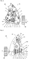
- the figure 1 shows a first embodiment of a watch winder block according to the present invention, seen from above.
- the winding block 307 comprises a mechanism for a watch.
- the mechanism comprises a base or base for a winding block 8 (made of steel or any other suitable material), an adjustment or control means, such as a crown of a winding stem or simply crown 305 (made of steel, copper , cuBe, in gold or any other suitable material) or a pusher, and a stem or winding rod 1 arranged to cooperate with the crown 305 (in steel, copper, cuBe, in gold or any other suitable material).
- the rod 1 is integral with the crown 305, both in rotation and in translation.
- the mechanism further comprises an elastic element, such as a return spring leaf or spring leaf 11, also called an impact-resistant spring leaf for a winding stem.
- the blade 11 is arranged between the base 8 and the rod 1, so as to resiliently recall the rod 1 in a normal position of use in the event of an impact, in particular on the crown 305.
- the blade 11 has a thickness of 0.4 mm for a length of approximately 15 mm, and these dimensions are valid for the other embodiments with the leaf spring 11. The thickness can be adjusted between 0.2 mm and 0.6 mm, without being limited to these values.
- the rod 1 faces a vertical portion of the base 8.
- the leaf spring 11 is made of metal, preferably steel. It is also possible to make it out of copper, cuBE, gold or any other suitable material. It is possible to produce the leaf spring 11 in a ductile material, for example so as to monitor the number of impacts of the rod 1 on the leaf spring 11, and thus to be aware of the general state of health of the watch.
- the leaf spring 11 makes it possible to prevent the rod 1 from abutting against the base 8 in the event of an impact, that is to say that an axial end of the rod 1, on the side opposite the crown 305, does not come into contact in the event of an impact with a wall of the base 8, situated on the side of the axial end of the rod 1.
- the rod 1 has a longitudinal axis X1, in the direction X , and the leaf spring 11 axially recalls the rod 1, by exerting an axial force on its bearing end.
- the wall of the base 8 is arranged facing the leaf spring 11 facing a first face of the leaf spring 11, and the leaf spring 11 is arranged facing the rod 1, relative to a second face of the leaf spring 11.
- the wall of the base 8 is positioned substantially perpendicular to the longitudinal axis X1 of the rod 1, that is to say on a plane substantially along YZ, and the leaf spring 11 is arranged between this base wall 8 and the rod 1, so as to avoid any damage.
- the longitudinal axis X1 of the rod 1 has an intersection with the face of the wall of the base 8, so that one wishes to avoid contact which risks damaging the rod 1, the elements associated with rod 1 and / or the base 8 in the event of an impact.
- the mechanism comprises, in cooperation with the rod 1, a pull tab 2 mounted on a pull tab bridge 6 using a pull pin 6.1 and recalled for a pull spring 7, a pull tab rocker, a pull spring 3.1, a sliding pinion 4 arranged to engage on the side of the crown 305 with a winding pinion 5 of the mechanism, making it possible to wind the barrel of the watch.
- the sliding pinion 4 is arranged to engage with a gear of small deflection 10, itself engaged with a gear of large deflection 10.1 mounted on a deflection bridge 9 of the mechanism, so as to allow adjustment of hours and minutes.
- the leaf spring 11 comprises a first portion, called the fixing portion at a first end and a second free portion at a second end.
- the free portion is arranged between two stops 11.1 and 11.2 of the base 8.
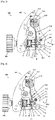
- the figure 2 shows the first embodiment of the watch winding block according to the present invention, seen from below.
- the reference numbers are repeated as necessary with reference to the figure 1 .
- the term “bottom view” is understood to mean the face opposite the top view, so called by the traditional positioning of such an adjustment or control system, in a watch case.
- the fixing portion 11.3 of the spring blade is fixed to the base 8 by means of a fixing screw 11.4 and the two fixing pins 11.5.
- the free portion of the spring leaf 11 is arranged in abutment against the abutment 11.2 of the base 8, so as to allow the axial return of the rod 1, and at a distance from the abutment 11.1 of the base 8.
- the leaf spring advantageously comprises a central portion 11.6 arranged against the base 8, preferably at a flat surface thereof, so as to shorten the lever arm of the leaf spring 11 and allows a greater return force, so increase the stiffness of the leaf spring 11.
- the rod 1 comprises a bearing portion or abutment portion 1.1 and a guide portion 1.2.
- the stopper portion 1.1 has a square section F of side 1.05 mm and the guide portion 1.2 has a diameter G of 0.7 mm.
- the side of the square section of the stopper portion 1.1 can be adjusted from 0.8 mm to 1.5 mm and the diameter of the guide portion 1.2 from 0.5 to 1.3 mm, without being limited to these values. These dimensions are valid for the other embodiments.
- the leaf spring 11 comprises an opening arranged to receive the guide portion 1.2 so as to guide the rod 1 in normal operation and in the event of an impact.
- the base 8 includes a leave 8.1 arranged opposite the guide portion 1.2, so as not to come into contact with the latter, and thus forms a guard distance S between the bottom of the leave 8.1 and the guide portion 1.2, typically 0.1 mm. As the leaf spring 11 is directly mounted on the base 8, few components enter the rib chain to calculate the guard distance S, this may be of small value, which provides good compactness.
- the leaf spring 11 comprises a contact or support surface arranged to form a stop against the support portion 1.1 of the rod 1.
- the leaf spring 11 is fixed on the base 8 and bears against the portion support 1.1 of the rod 1, so as to provide an elastic restoring support on the rod 1, in particular in the event of an impact.
- the leaf spring 11 comprises a first substantially planar surface arranged opposite the wall of the base 8, at the stop 11.2 of the base 8, so as to form a first stop.
- the leaf spring 11 also comprises another substantially planar surface arranged opposite the wall of the base 8, at the level of the central portion 11.6 of the leaf spring 11.
- the leaf spring 11 further comprises a second substantially plane surface arranged in look of the stop portion 1.1 of the rod 1, so as to form a second stop.
- the leaf spring 11 by axially recalling the rod 1, prevents the end of the rod 1, on the side opposite to the crown 305, from abutting or striking against the base 8, at a level leave 8.1 of the base 8 intended to receive the end of the rod 1 in normal operation.
- the leaf spring 11 thus recalls the rod 1 in normal position of operation or use.
- the figure 3 shows a second embodiment of the watch winding block according to the present invention, seen from below.
- the leaf spring 11 is arranged at a safety distance D from the base 8 at the stop 11.2 of the base 8 substantially along the axis X, so as to allow the establishment of a safety stroke in the event impact of the support portion 1.1 of the rod 1 on the leaf spring 11, so as to avoid contact between the guide portion 1.2 of the rod 1 with the base 8 or with the bottom of the base leave 8, as well as allowing the axial return of the rod 1.
- the safety distance D is 0.5 mm to 1 mm, preferably 0.66 mm.
- the central portion 11.6 of the rod 11 is also arranged at another safety distance from the base 8 between 0.2 and 0.5 mm, preferably 0.33 mm.
- the leaf spring 11 is mounted in tension or by force against the stop 11.1, using the fixing portion 11.3 fixed to the base 8 by the fixing screw 11.4 and the pins 11.5.
- This tensioning makes it possible to exert a large axial return force, so as to increase the stiffness of the leaf spring 11.
- the figure 4 shows a third embodiment of the watch winding block according to the present invention, seen from below.
- the leaf spring 11 has a substantially sinusoidal or wave-shaped shape, in which the central portion 11.6 is arranged against the base 8 at a support face 11.8 and the free end is arranged against the base 8 at the stop 11.2 of the base 8 so as to form a beam between these two support points.
- These two supports 11.2, 11.8 are formed at a clearance 15 from the base 8.
- the leaf spring has between these two support points a substantially planar surface arranged opposite the support portion 1.1 of the rod 1 , so as to allow the rod 1 to be returned by exerting an axial force against it.
- the sinusoidal or wave-shaped form allows the restoring effort to be adjusted by construction as a function of the distance between the two support points and the height of the wave between these two support points and the face arranged in view of the support portion 1.1 of the rod 1.
- the distance between the two support points is greater than the diameter of the sliding pinion 4, which facilitates construction and provides a good shockproof function.
- the figure 5 shows a fourth embodiment of the watch winding block according to the present invention, seen from below.
- the leaf spring 11 has a shape of a tuning fork.
- the central portion 11.6 of the spring leaf 11 is divided into two branches 11.7 on the side opposite to the fixing portion 11.3.
- the central portion 11.6 has a thickness E of 0.4 mm, and the two branches 11.7 have a thickness P of 0.4 mm, and are spaced by the dimension N of 1.85 mm between their outer flanks.
- the two branches 11.7 are spaced by the distance K allowing the stroke of the rod 1 to be adjusted in the event of an impact.
- the distance L between the two external flanks of the ends of branches 11.7 is 1.55 mm, which implies a dimension of 0.75 mm for dimension K.
- the diapason shape of the spring leaf 11 offers an excellent shock-absorbing function because it allows absorb the shock on the branch on the side of the crown 305 and has a large contact surface with the base, which makes it possible not to damage the parts by matting.
- the dimension H between the internal blank of the branch 11.7 on the side of the crown 305 and the external flank of the branch 11.7 on the side opposite to the crown 305 is 1.45 mm.
- the dimension M between the base of the crown 305 and the external flank of the branch 11.7 on the side of the crown 305 is 9.65 mm.
- the dimension Q between the ends of the branches 11.7 and the opposite part of the fixing portion 11.3 is 14.92 mm.
- the two branches 11.7 are folded towards each other at the end opposite the fixing portion 11.3.
- the stopper portion 1.1 has a square section F of side 1.05 mm and the guide portion 1.2 has a diameter G of 0.7 mm.
- the leaf spring 11 includes openings arranged to receive the guide portion 1.2 so as to guide the rod 1 in normal operation and in the event of an impact.
- a first opening is made in the branch 11.7 on the side of the crown 305 to allow passage to the guide portion 1.2.
- an abutment portion or contact surface between the branch 11.7 on the side of the crown 305 and the abutment portion 1.1 of the rod 1.
- a second opening in the blade 11, at the level of the branch 11.7 on the side opposite to the crown 305 is provided so as to provide a passage to the guide portion 1.2. This makes it possible to resiliently recall the rod 1, by cooperating with the first branch 11.7, on the side of the crown 305.
- the figure 6 shows an alternative to the fourth embodiment of the watch winding block according to the present invention, seen from below.
- the branch 11.7 of the leaf spring 11 on the side of the crown 305 has an alternative shape to the shape of the figure 5 .
- the branch 11.7 on the side of the crown 305 is straight in shape at the end, rather than folded towards the other branch 11.7. This makes it possible to adjust the rigidity of the blade 11 as required.
- the figure 7 shows a fifth embodiment of the watch winder block according to the present invention, seen from below.
- the elastic element comprises at least one belleville washer 13, and the base 8 further comprises a belleville washer wear plate 12 and belleville washer wear plate screws 12.1, in order to attach the bellevile washer washer wear plate 12 to the base 8.
- the washers can be stacked in series or in parallel, or a combination of series or parallel in order to achieve the correct elasticity adjustment for a given belleville washer.
- the combination of Belleville washers in series or in parallel makes it possible to adjust the load and the deflection.
- Said at least one belleville washer 13 is arranged between the end of the rod 1 and of its support portion 1.1 and the base 8, at the level of the wear plate 12, like an insert on the base 8 and being part of it. In other words, the belleville washer 13 is in abutment against the base 8.
- the distance separating R the stop portion 1.1 having the square section F of side 1.05 mm and the wear plate 12 is approximately 0.5 mm to 1 mm, preferably 0.91 mm.
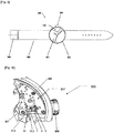
- the figure 8 represents a watch case.
- the watch case 302 or watch case is adapted to receive the winding block 307.
- the watch case 302 can further or alternatively comprise at least one suspension means, such as a shockproof spring clip 306, arranged between a watch movement 301 of watch 300 and the structural portion of the watch case.
- a shockproof spring clip 306 arranged between a watch movement 301 of watch 300 and the structural portion of the watch case.
- watch 302. This makes it possible to absorb shocks at the level of at least one shockproof spring flange 306 and not to impact the watch movement 301, nor its smooth running. This also makes it possible to suspend the functional part of watch 300 (clockwork mechanism 100, winding block 307 and / or watch movement 301) relative to the structural part of watch 300 (watch case 302 or platinum).
- winding block 307 can be mounted on the structure of the watch case 302 or on the plate by means of such shock-absorbing spring flanges 306.
- a shock at the middle of the watch 300 or at the level of the crown 305 is absorbed by the shock-absorbing spring flanges 306 and / or by the spring blade 11.
- the spring shockproof strap 306 comprises fixing means, such as fixing screws, pins or a protruding portion arranged to be held or pinched in a slot of the watch case 302 in order to fix the shockproof strap 306 from one side to the structural part of watch 300 (watch case 302, watch plate 300) and the other part of the functional part of watch 300 (clock mechanism 100, winding block 307 and / or watch movement 301), as well as at least one spring-shaped portion or spring portion.
- This spring portion can be a flat spring forming a lamella tortuous or sinuous, a spiral spring, a slender strip or any other form of spring.
- the spring shockproof flange 306 comprises elastic return means from the functional part of watch 300 to the structural part of watch 300, so as to create a suspension and absorb shock.
- This suspension makes it possible to isolate the functional part from shocks to avoid a temporal drift of the watch 300 or damage to components of the watch 300.
- the shockproof spring flange 306 can be made of steel, copper, cuBe, gold or any other suitable material.
- the figure 9 schematically represents the watch.
- the watch 300 includes the complete watch mechanism 301 allowing the movement of the hour, minute and second hands and in particular comprising the mechanism 100, and the watch case 302.
- the crown 305 allows the user of the watch 300 to adjust watch 300, in particular to allow winding and / or fine adjustment and positioning of the hands.
- the watch 300 further comprises a strap 303 and a fastening system 304, so as to allow the watch to be worn on the user's wrist.
- the watch further includes a movement and an oscillating system, such as a balance coupled to a hairspring.
- an oscillating system such as a balance coupled to a hairspring.
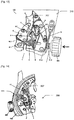
- the figure 10 shows a detail view of the watch 300.
- the watch 300 comprises the case 302 with a bottom, a bezel and the middle part forming the lateral portion of the case.
- the watch 300 includes the movement 301 and the crown 305.
- the leaf spring 11 is shown in its environment against the stop piece 11.1 and the rod 1.
- the sliding pinion 4 is shown with the winding pinion 5.
- the winding block is also shown attached to the plate.
- the figure 11 shows another detail view of watch 300, in which the leaf spring is fixed directly to the plate.
- the watch 300 includes the housing 302 and the crown 305.
- the leaf spring 11 is fixed on the plate and protects the rod 1 from an impact against the base.
- the sliding pinion 4 and the winding pinion 5 are also shown.
- the figure 12 represents an alternative embodiment of the clock mechanism.
- the figure 12 shows an alternative embodiment of the clock mechanism in which the spring blade is arranged between the winding block and the crown.
- the leaf spring 11 is fixed to the plate 310 and is arranged between the winding block and the crown 305.
- the other reference numbers are repeated as necessary.
- the leaf spring 11 can also be positioned on the winding block 307, near the pull tab bridge 6, between the pull tab bridge 6 and the outer edge of the winding block.
- the figure 13 shows the variant of the timepiece mechanism in which the spring blade is arranged between the winding block and the crown, in the impact position.
- the figure 14 shows a detail view of the watch with the shockproof strap and the leaf spring mounted on the winding block, seen from below.
- the watch 300 includes at least one shockproof strap 306 which connects the housing 302 to the winding block 307, so as to absorb shocks.
- the figure 15 shows a detail view of the watch with the shockproof strap and the leaf spring mounted on the winding block, seen from above.
- the watch 300 is shown in top view in order to show that the watch 300 includes shockproof flanges on each front and rear face of the winding block 307.
- the figure 16 shows a detail view of the watch with the shockproof strap and the leaf spring mounted on the plate.
- the watch 300 comprises at least one shockproof flange 306 connecting the housing 302 to the plate 310, so as to absorb shocks.
- the figure 17 shows a detail view of the watch with several shockproof flanges and the leaf spring mounted on the plate.
- the watch 300 includes several shockproof flanges 306 connecting the plate 310 to the housing 302.
- shockproof flanges are shown in figure 17 with the leaf spring, it is entirely possible to provide a watch with the shockproof flanges 306 without the leaf spring 11.
- shockproof flange 306 between the plate 310 and the winding block 307.
- shockproof strap on a bridge or on the dial, in the same way, in particular for the case where the shockproof strap is fixed to the winding block.
Abstract
Mécanisme d'horlogerie (100) comprenant :- une embase (8),- un moyen de réglage ou de commande de la montre (305), tel qu'une couronne de remontoir ou un poussoir, et- une tige (1) agencée pour coopérer avec ledit moyen de réglage ou de commande (305),caractérisé en ce que :- la tige (1) comprend une portion d'appui,- le mécanisme (100) comprend en outre au moins un élément élastique (11) fixé sur l'embase et en appui sur la portion d'appui de la tige (1), de sorte à procurer un appui élastique de rappel sur la tige (1), en cas de choc.Clock mechanism (100) comprising: - a base (8), - a means for adjusting or controlling the watch (305), such as a winding crown or a push-piece, and - a rod (1) arranged to cooperate with said adjustment or control means (305), characterized in that: - the rod (1) comprises a support portion, - the mechanism (100) further comprises at least one elastic element (11) fixed on the base and resting on the bearing portion of the rod (1), so as to provide an elastic restoring support on the rod (1), in the event of impact.
Description
La présente invention concerne de manière générale un mécanisme de montre avec un dispositif de réglage ou de commande, tel qu'une couronne de remontoir ou un poussoir.The present invention relates generally to a watch mechanism with an adjustment or control device, such as a winding crown or a push-piece.
Il est connu dans l'art antérieur des dispositifs de réglage ou de commande, tels que les couronnes ou les poussoirs.It is known in the prior art to adjust or control devices, such as crowns or pushers.
Le document
En contrepartie, ce système présente notamment l'inconvénient d'être encombrant, de s'étendre extérieurement à la carrure et de nécessiter une intervention de l'utilisateur de la montre pour démasquer la couronne afin de s'en servir.In return, this system has the particular disadvantage of being bulky, of extending outwardly to the middle part and of requiring intervention by the user of the watch to unmask the crown in order to use it.
Un but de la présente invention est de répondre aux inconvénients du document de l'art antérieur mentionné ci-dessus et en particulier, tout d'abord, de proposer une montre et un mécanisme de montre permettant, outre une amélioration esthétique, de protéger les dispositifs de réglage ou de commande, tels que les couronnes ou les poussoirs, et les éléments coopérant avec ceux-ci, d'éviter un enclenchement inopiné ou une détérioration en cas de chocs. La présente invention permet également de réduire l'encombrement de la montre et de ne pas nécessiter une intervention du porteur de la montre pour démasquer les dispositifs de réglage ou de commande.An object of the present invention is to respond to the drawbacks of the document of the prior art mentioned above and in particular, first of all, to propose a watch and a watch mechanism making it possible, in addition to an aesthetic improvement, to protect the adjustment or control devices, such as crowns or pushers, and the elements cooperating with them, to avoid an unexpected engagement or deterioration in the event of impacts. The present invention also makes it possible to reduce the size of the watch and not to require an intervention by the wearer of the watch to unmask the adjustment or control devices.
Pour cela, un premier aspect de l'invention concerne un mécanisme d'horlogerie pour montre comprenant :
- une embase,
- un moyen de réglage ou de commande de la montre, tel qu'une couronne de remontoir ou un poussoir, et
- une tige agencée pour coopérer avec ledit moyen de réglage ou de commande, caractérisé en ce que :
- la tige comprend une portion d'appui,
- le mécanisme comprend en outre au moins un élément élastique fixé ou en appui sur l'embase et en appui sur la portion d'appui de la tige, de sorte à procurer un appui élastique de rappel sur la tige, en cas de choc.
- a base,
- a means of adjusting or controlling the watch, such as a winding crown or a push-piece, and
- a rod arranged to cooperate with said adjustment or control means, characterized in that:
- the rod comprises a bearing portion,
- the mechanism further comprises at least one elastic element fixed or supported on the base and bearing on the bearing portion of the rod, so as to provide an elastic restoring support on the rod, in the event of impact.
Ceci permet de protéger la tige et le moyen de réglage ou de commande associé ainsi que l'embase, la platine et le mouvement de la montre, de sorte à ne pas endommager ceux-ci en cas de chocs, qui peuvent avoir lieu sur le moyen de réglage ou de commande lorsque la montre chute, du fait du poids supplémentaire de ceux-ci déséquilibrant la montre, ou avoir lieu à un autre endroit sur une carrure de la montre. Ceci permet également de rappeler élastiquement la tige dans la positon normale d'utilisation, de sorte à ce que la tige ne bute pas anormalement contre l'embase en cas de chocs, ce qui pourrait endommager l'ensemble du système ou enclencher inopinément une fonction de la montre liée à la tige. De plus, ceci permet de protéger la tige et le moyen de réglage ou de commande, tel que la couronne de remontoir ou le poussoir, en cas de jeu de celui-ci avec une carrure de la montre.This protects the rod and the associated adjustment or control means as well as the base, the plate and the movement of the watch, so as not to damage them in the event of impacts, which may take place on the means of adjustment or control when the watch falls, due to the additional weight of these unbalancing the watch, or take place in another place on a middle part of the watch. This also makes it possible to resiliently recall the rod in the normal position of use, so that the rod does not abut abnormally against the base in the event of impact, which could damage the whole system or unexpectedly activate a function of the watch linked to the stem. In addition, this makes it possible to protect the stem and the adjustment or control means, such as the winding crown or the pusher, in the event of play of the latter with a middle part of the watch.
On entend par embase une partie d'une pièce servant de support ou d'appui. La tige est agencée pour coopérer avec ledit moyen de réglage ou de commande, c'est-à-dire que la tige est solidaire du moyen de réglage ou de commande au moins en rotation ou en translation, de sorte à permettre le réglage ou la commande de fonction de montre, tel que le remontage d'un barillet de réserve de marche, le réglage des heures, minutes, secondes, le réglage des dates ou jours, le réglage de phase de lune, le réglage de sonnerie, la commande d'un chronographe ou chronomètre, la commande d'un dispositif d'arrêt ou de réglage de balancier ou de tourbillon, la commande d'une fonction décorative ou d'indication de l'heure à la demande, ou toute autre fonction similaire ou proche. Ainsi l'élément élastique protège la pièce sur laquelle il est fixé ou en appui d'un choc de la tige. En conséquence, peu de composants entrent dans la chaîne de côtes, et il est ainsi plus aisé de maîtriser la chaîne de côtes entre l'embase, la tige et l'élément élastique de sorte à assurer correctement la fonction antichoc sans gêner le fonctionnement normal du moyen de réglage, nécessitant un ajustement très précis des pièces et composants entre eux. Ceci permet également d'assurer une surface de contact suffisante entre l'élément élastique et l'embase, de sorte à ne pas abîmer ou mater l'embase, et ne pas perturber un système oscillant du mouvement de la montre.By base is meant a part of a part serving as support or support. The rod is arranged to cooperate with said adjustment or control means, that is to say that the rod is integral with the adjustment or control means at least in rotation or in translation, so as to allow adjustment or watch function control, such as winding a power reserve barrel, setting the hours, minutes, seconds, setting the dates or days, setting the moon phase, setting the ring, setting the '' a chronograph or stopwatch, control of a balance or tourbillon stop or adjustment device, control of a decorative function or indication of the time on demand, or any other similar or similar function . Thus the elastic element protects the part on which it is fixed or in support of a shock from the rod. Consequently, few components enter the rib chain, and it is thus easier to control the rib chain between the base, the rod and the elastic element so as to correctly ensure the shockproof function without interfering with normal operation. adjustment means, requiring a very precise adjustment of parts and components to each other. This also ensures a sufficient contact surface between the elastic element and the base, so as not to damage or mat the base, and not to disturb an oscillating system of the movement of the watch.
Avantageusement, l'élément élastique est une lame ressort de rappel, agencée pour exercer un effort axial sur la tige.Advantageously, the elastic element is a return spring blade, arranged to exert an axial force on the rod.
Ceci permet de rappeler la tige en positon normale d'utilisation, et de maintenir la tige éloignée d'une positon anormale d'utilisation en cas de choc où la tige vient buter contre l'embase ce qui risque d'endommager la tige, l'embase et/ou l'ensemble du mécanisme associé, ou risque de déclencher inopinément la ou les fonctions de montre associées au moyen de réglage ou de commande.This allows the rod to be returned to the normal position for use, and to keep the rod away from an abnormal position for use in the event of an impact where the rod abuts against the base, which risks damaging the rod, l 'base and / or all of the associated mechanism, or may unexpectedly trigger the watch function (s) associated with the adjustment or control means.
Avantageusement, le mécanisme d'horlogerie pour montre comprend en outre un organe de contrôle, tel qu'un pignon coulant, coopérant avec le moyen de réglage ou de commande, et dans lequel l'élément élastique est agencé entre l'organe de contrôle et l'embase.Advantageously, the clockwork mechanism for a watch further comprises a control member, such as a sliding pinion, cooperating with the adjustment or control means, and in which the elastic element is arranged between the control member and the base.
Ceci permet de proposer un mécanisme d'horlogerie pour montre avec une fonction efficace antichoc, tout en assurant de ne pas gêner le fonctionnement de l'organe de contrôle, grâce à un positionnement précis et dans l'ordre suivant de l'embase, l'élément élastique, et l'organe de contrôle.This makes it possible to propose a clockwork mechanism for a watch with an effective shockproof function, while ensuring not to hinder the operation of the control member, thanks to precise positioning and in the following order of the base, the elastic element, and the control member.
Avantageusement, la lame ressort ou lame ressort de rappel est agencée à une distance de sécurité de l'embase.Advantageously, the spring blade or return spring blade is arranged at a safe distance from the base.
Ceci permet de garder une distance de sécurité de la lame ressort face à l'embase, de sorte à absorber un choc le long de la distance de sécurité.This makes it possible to keep a safety distance from the spring blade facing the base, so as to absorb a shock along the safety distance.
Avantageusement, la lame ressort est montée en tension, de sorte à exercer un effort de rappel supérieur à un seuil prédéterminé, et à empêcher la tige de parcourir la distance de sécurité en cas de choc de faible ampleur.Advantageously, the leaf spring is mounted in tension, so as to exert a restoring force greater than a predetermined threshold, and to prevent the rod from traveling the safety distance in the event of a shock of small magnitude.
Ceci permet de protéger la tige et les éléments associés en cas de choc, et d'éviter le déclenchement intempestif de fonction de montre, grâce à un effort de rappel vigoureux.This makes it possible to protect the stem and the associated elements in the event of an impact, and to avoid inadvertent triggering of the watch function, thanks to a vigorous restoring effort.
Avantageusement, la distance de sécurité est inférieure à une distance séparant la couronne de l'embase, dans un sens axial de la tige.Advantageously, the safety distance is less than a distance separating the crown from the base, in an axial direction of the rod.
Ceci permet d'assurer la protection de la couronne en cas de choc, de sorte à assurer une butée de la tige empêchant un contact de la couronne sur l'embase ou sur la carrure de la montre.This ensures protection of the crown in the event of an impact, so as to ensure a stop for the rod preventing contact of the crown on the base or on the middle of the watch.
Avantageusement,
- la tige présente un axe longitudinal,
- l'embase comprend une surface plane en regard de l'axe longitudinal de la tige, et
- la lame ressort comprend une première surface plane en regard de l'axe longitudinal de la tige et agencée en regard de la surface plane de l'embase, de sorte à former une première butée.
- the rod has a longitudinal axis,
- the base comprises a flat surface facing the longitudinal axis of the rod, and
- the leaf spring comprises a first flat surface opposite the longitudinal axis of the rod and arranged opposite the flat surface of the base, so as to form a first stop.
Avantageusement,
- la tige présente un axe longitudinal,
- l'embase comprend une surface plane intersectant l'axe longitudinal de la tige, et
- la lame ressort comprend une première surface plane intersectant l'axe longitudinal de la tige et agencée en regard de la surface plane de l'embase, de sorte à former une première butée, du coté opposé à la couronne.
- the rod has a longitudinal axis,
- the base comprises a flat surface intersecting the longitudinal axis of the rod, and
- the leaf spring comprises a first flat surface intersecting the longitudinal axis of the rod and arranged opposite the flat surface of the base, so as to form a first stop, on the side opposite to the crown.
Avantageusement,
- la tige présente un axe longitudinal,
- l'embase comprend une surface plane perpendiculaire à l'axe longitudinal de la tige, et
- la lame ressort comprend une première surface plane perpendiculaire à l'axe longitudinal de la tige et agencée en regard de la surface perpendiculaire de l'embase, de sorte à former une première butée.
- the rod has a longitudinal axis,
- the base comprises a flat surface perpendicular to the longitudinal axis of the rod, and
- the leaf spring comprises a first planar surface perpendicular to the longitudinal axis of the rod and arranged opposite the perpendicular surface of the base, so as to form a first stop.
On entend ici par intersectant le fait que la surface plane de l'embase présente une intersection avec l'axe longitudinal de la tige, abstraction faite d'un congé ménagé dans la surface plane de l'embase de sorte à recevoir une extrémité de la tige.By intersecting here is meant the fact that the flat surface of the base has an intersection with the longitudinal axis of the rod, apart from a leave formed in the flat surface of the base so as to receive one end of the rod.
Ceci permet de former une première butée afin d'assurer un contact de la lame ressort contre l'embase, de sorte à protéger la tige et le mécanisme associé de réglage et de commande.This makes it possible to form a first stop in order to ensure contact of the leaf spring against the base, so as to protect the rod and the associated adjustment and control mechanism.
Avantageusement, la lame ressort est agencée en appui au niveau de deux surfaces contre l'embase de sorte à former une poutre, visant à faire obstacle à la tige au niveau d'un porte-à-faux et à exercer un effort de rappel axial sur la tige en cas de choc, en modifiant un bras de levier.Advantageously, the leaf spring is arranged in abutment at two surfaces against the base so as to form a beam, aiming to obstruct the rod at a cantilever and to exert an axial restoring force. on the rod in the event of an impact, by modifying a lever arm.
Ceci permet de proposer une fonction de rappel de la tige de sorte à la protéger en cas de choc, de même que les éléments de mécanismes associés.This makes it possible to propose a return function of the rod so as to protect it in the event of an impact, as well as the elements of associated mechanisms.
Avantageusement, la lame ressort comprend une surface plane agencée en regard de la portion d'appui de la tige, de sorte à former une butée.Advantageously, the leaf spring comprises a flat surface arranged opposite the bearing portion of the rod, so as to form a stop.
Avantageusement,
- la tige comprend une portion d'appui, et
- la lame ressort comprend une surface d'appui ou de contact, de préférence plane, agencée en regard de la portion d'appui de la tige, de sorte à former une butée.
- the rod includes a bearing portion, and
- the leaf spring comprises a bearing or contact surface, preferably planar, arranged opposite the bearing portion of the rod, so as to form a stop.
Avantageusement,
- la tige comprend une portion d'appui, et
- la lame ressort comprend une surface plane agencée en regard de la portion d'appui de la tige, de sorte à former une butée.
- the rod includes a bearing portion, and
- the leaf spring comprises a flat surface arranged opposite the bearing portion of the rod, so as to form a stop.
Avantageusement,
- la tige comprend une portion d'appui, et
- la lame ressort comprend une deuxième surface plane agencée en regard de la portion d'appui de la tige, de sorte à former une deuxième butée.
- the rod includes a bearing portion, and
- the leaf spring comprises a second flat surface arranged opposite the bearing portion of the rod, so as to form a second stop.
Avantageusement,
- la tige comprend une portion d'appui, et
- la lame ressort comprend une deuxième surface plane intersectant l'axe longitudinal de la tige et agencée en regard de la portion d'appui de la tige, de sorte à former une deuxième butée, du côté de la couronne.
- the rod includes a bearing portion, and
- the leaf spring comprises a second flat surface intersecting the longitudinal axis of the rod and arranged opposite the bearing portion of the rod, so as to form a second stop, on the side of the crown.
Avantageusement,
- la tige comprend une portion d'appui, et
- la lame ressort comprend une deuxième surface plane perpendiculaire à l'axe longitudinal de la tige et agencée en regard de la portion d'appui de la tige, de sorte à former une deuxième butée.
- the rod includes a bearing portion, and
- the leaf spring comprises a second flat surface perpendicular to the longitudinal axis of the rod and arranged opposite the bearing portion of the rod, so as to form a second stop.
Ceci permet de protéger la tige et les éléments associés, en formant une deuxième butée agencée pour entrer un contact avec la tige en cas de choc.This makes it possible to protect the rod and the associated elements, by forming a second stop arranged to come into contact with the rod in the event of an impact.
Avantageusement,
- la tige comprend une extrémité de guidage, et
- la lame ressort comprend en outre une ouverture agencée pour recevoir l'extrémité de guidage.
- the rod includes a guide end, and
- the leaf spring further comprises an opening arranged to receive the guide end.
Avantageusement,
- la tige comprend une extrémité de guidage calibrée, et
- la lame ressort comprend en outre une ouverture calibrée agencée pour recevoir l'extrémité de guidage.
- the rod comprises a calibrated guide end, and
- the leaf spring further comprises a calibrated opening arranged to receive the guide end.
Ceci permet de protéger la tige tout en ménageant une ouverture de sorte à guider la tige, tant en fonctionnement normal qu'en cas de choc. Ainsi, la lame ressort est positionnée de façon très précise. Il est alternativement possible de prévoir une forme de fourchette pour enfiler la lame ressort sur la tige, de sorte à faciliter le montage.This protects the rod while providing an opening so as to guide the rod, both in normal operation and in the event of an impact. Thus, the leaf spring is positioned very precisely. It is alternatively possible to provide a form of fork for threading the leaf spring on the rod, so as to facilitate assembly.
Avantageusement, la surface plane de l'embase comprend un congé agencé pour recevoir l'extrémité de guidage.Advantageously, the flat surface of the base includes a leave arranged to receive the guide end.
Ceci permet d'éviter tout contact de la tige avec l'embase en fonctionnement normal.This avoids any contact of the rod with the base in normal operation.
Avantageusement, le mécanisme comprend en outre une pièce de butée du côté de la couronne, et dans lequel la lame ressort est agencée entre l'embase et la pièce de butée, et agencée en tension contre la pièce de butée, de sorte à former une autre butée.Advantageously, the mechanism further comprises a stop piece on the side of the crown, and in which the spring leaf is arranged between the base and the stop piece, and arranged in tension against the stop piece, so as to form a another stop.
Avantageusement, le mécanisme comprend en outre une pièce de butée, et dans lequel la lame ressort est agencée entre l'embase et la pièce de butée, de sorte à former une troisième butée.Advantageously, the mechanism further comprises a stop piece, and in which the leaf spring is arranged between the base and the stop piece, so as to form a third stop.
En d'autres termes, la pièce de butée du côté de la couronne est solidaire de la l'embase du côté de la couronne, pouvant être une pièce rapportée sur l'embase ou directement une portion de l'embase. La lame ressort est ainsi agencée entre la pièce de butée et l'embase ou entre deux parois de l'embase et est agencée entre la tige et la paroi de l'embase du côté opposé à la couronne.In other words, the abutment part on the side of the crown is integral with the base on the side of the crown, which can be an insert on the base or directly a portion of the base. The leaf spring is thus arranged between the abutment piece and the base or between two walls of the base and is arranged between the rod and the wall of the base on the side opposite to the crown.
Ceci permet de monter en tension la lame ressort et ainsi exercer un rappel raide de la tige, de sorte à limiter tout mouvement intempestif en cas de choc.This allows the spring blade to be tensioned and thus exert a stiff return to the rod, so as to limit any untimely movement in the event of an impact.
Avantageusement, la lame ressort comprend une portion de fixation agencée pour être solidaire de l'embase.Advantageously, the leaf spring comprises a fixing portion arranged to be integral with the base.
Ceci permet de fixer la lame ressort à l'embase en réduisant l'encombrement, en étant éloigné ou agencé à distance des différentes butées et surfaces de contact, de sorte à obtenir un élancement propre à former une lame ressort.This makes it possible to fix the leaf spring to the base by reducing the bulk, by being distant or arranged at a distance from the various stops and contact surfaces, so as to obtain a slenderness capable of forming a leaf spring.
Avantageusement, la lame ressort présente une section variable, de sorte à ajuster l'effort de rappel.Advantageously, the leaf spring has a variable section, so as to adjust the return force.
Avantageusement, la lame ressort comprend, entre la surface d'appui et la portion de fixation, deux portions d'ajustement présentant chacune une élasticité différente.Advantageously, the leaf spring comprises, between the bearing surface and the fixing portion, two adjustment portions, each having a different elasticity.
Avantageusement, une des portions d'ajustement présente une section d'une première dimension, et l'autre portion d'ajustement présente une section d'une deuxième dimension.Advantageously, one of the adjustment portions has a section of a first dimension, and the other adjustment portion has a section of a second dimension.
Avantageusement, la portion d'ajustement du côté de la portion de fixation présente une section plus important que la section de l'autre portion d'ajustement.Advantageously, the adjustment portion on the side of the fixing portion has a larger section than the section of the other adjustment portion.
Avantageusement, les deux portions d'ajustement sont reliées par une portion de matière affaiblie.Advantageously, the two adjustment portions are connected by a portion of weakened material.
Avantageusement, les deux portions d'ajustement sont reliées par une pièce en matière élastique, tel que du caoutchouc.Advantageously, the two adjustment portions are connected by a piece of elastic material, such as rubber.
Ceci permet d'ajuster l'élasticité de la lame ressort de sorte à améliorer la fonction antichoc.This allows the elasticity of the spring blade to be adjusted so as to improve the shockproof function.
Un deuxième aspect de la présente invention concerne un bloc de remontoir comprenant au moins un mécanisme d'horlogerie selon le premier aspect.A second aspect of the present invention relates to a winding block comprising at least one clockwork mechanism according to the first aspect.
Ceci permet de proposer un mécanisme sous forme de bloc, de sorte à permettre un montage aisé et modulaire sur une platine de montre, ainsi que de faciliter son remplacement. L'embase est alors l'embase du bloc.This makes it possible to propose a mechanism in the form of a block, so as to allow easy and modular mounting on a watch plate, as well as to facilitate its replacement. The base is then the base of the block.
Un troisième aspect de la présente invention est une montre comprenant au moins un mécanisme selon le premier aspect.A third aspect of the present invention is a watch comprising at least one mechanism according to the first aspect.
Ceci permet de proposer une montre avec un encombrement réduit, un esthétisme amélioré, une protection du ou des moyens de réglage ou de commande efficace en cas de choc, ainsi que d'empêcher un déclenchement inopiné de fonction de montre en cas de choc, et de ne pas nécessiter d'intervention du porteur de montre pour désengager le dispositif de protection. L'embase du mécanisme est alors directement une platine de la montre.This makes it possible to propose a watch with a reduced bulk, an improved aesthetic appearance, protection of the adjustment means or effective control in the event of an impact, as well as to prevent an unexpected triggering of the watch function in the event of an impact, and not to require intervention by the watch wearer to disengage the protection device. The mechanism base is then directly a watch plate.
Un quatrième aspect concerne une montre comprenant une platine et au moins un bloc de remontoir selon le deuxième aspect, monté sur la platine.A fourth aspect relates to a watch comprising a plate and at least one winding block according to the second aspect, mounted on the plate.
Ceci permet de proposer une montre ayant les mêmes avantages que la montre du troisième aspect, au surplus permettant d'installer le bloc de remontoir de façon modulaire, soit au temps de la première monte, soit au cours d'une révision périodique de la montre.This makes it possible to propose a watch having the same advantages as the watch of the third aspect, moreover making it possible to install the winding block in a modular fashion, either during the time of the first assembly, or during a periodic revision of the watch. .
Un cinquième aspect de la présente invention concerne une montre comprenant un boîtier de montre, une platine et un mouvement de montre, et comprenant en outre au moins un moyen de suspension, tel qu'une bride antichoc ressort, agencé entre au moins l'un parmi la platine et le boitier de montre et au moins l'un parmi le mouvement de montre, le bloc de remontoir selon le deuxième aspect ou le mécanisme d'horlogerie selon le premier aspect.A fifth aspect of the present invention relates to a watch comprising a watch case, a plate and a watch movement, and further comprising at least one suspension means, such as a shockproof spring clip, arranged between at least one among the plate and the watch case and at least one among the watch movement, the winding block according to the second aspect or the clockwork mechanism according to the first aspect.
Ceci permet de protéger la tige et le moyen de réglage ou de commande associé, le bloc de remontoir ou le mouvement de montre, de sorte à ne pas endommager ceux-ci en cas de chocs, qui peuvent avoir lieu sur le moyen de réglage ou de commande lorsque la montre chute, du fait du poids supplémentaire de ceux-ci déséquilibrant la montre, ou avoir lieu à un autre endroit sur une carrure de la montre.This makes it possible to protect the rod and the associated adjustment or control means, the winding block or the watch movement, so as not to damage them in the event of impacts, which may take place on the adjustment means or control when the watch falls, due to the additional weight of these unbalancing the watch, or take place at another location on a middle part of the watch.
Ceci permet également de rappeler élastiquement le mécanisme d'horlogerie, le bloc de remontoir ou le mouvement de montre dans une dans une positon normale d'utilisation, de sorte à ce que les éléments ne butent pas anormalement contre le boitier de la montre ou la platine en cas de chocs, ce qui pourrait endommager l'ensemble du système ou enclencher inopinément une fonction de la montre.This also makes it possible to resiliently recall the clockwork mechanism, the winding block or the watch movement in a in a position normal use, so that the elements do not abut abnormally against the watch case or the plate in case of impact, which could damage the whole system or unexpectedly start a watch function.
Ceci permet en outre une coopération avec l'élément élastique, tel que la lame ressort de rappel, agencé pour exercer un effort axial sur la tige, notamment dans le cas d'un choc sur le moyen de réglage ou de commande, tel que la couronne de remontoir ou le poussoir. En cas de choc, le mouvement de montre est déplacé en direction de la couronne et l'élément élastique permet de protéger la tige (de remontoir) afin qu'elle ne bute pas contre l'embase ou le fond de son logement.This also allows cooperation with the elastic element, such as the return spring blade, arranged to exert an axial force on the rod, in particular in the event of a shock on the adjustment or control means, such as the winding crown or pusher. In the event of an impact, the watch movement is moved in the direction of the crown and the elastic element protects the stem (winding) so that it does not abut against the base or the bottom of its housing.
Avantageusement, la au moins une bride antichoc ressort comprend des moyens de fixation, tel que des vis de fixations ou une portion saillante agencée pour être maintenue dans une fente du boîtier de montre ou une combinaison des deux, et au moins une portion ressort.Advantageously, the at least one shock-absorbing spring flange comprises fixing means, such as fixing screws or a projecting portion arranged to be held in a slot of the watch case or a combination of the two, and at least one spring portion.
Avantageusement, la portion ressort comprend un ressort plat formant une lamelle tortueuse ou sinueuse, un ressort spiral ou une lamelle élancée.Advantageously, the spring portion comprises a flat spring forming a tortuous or sinuous lamella, a spiral spring or a slender lamella.
Ceci permet de proposer des moyens de suspension ou de rappel élastique agencés entre une partie structurelle de la montre (telle que le boîtier ou la platine) et une partie fonctionnelle de la montre (telle que le mécanisme de montre, le bloc remontoir, ou le mouvement de montre), et permet d'éviter toute dérive temporelle de la partie fonctionnelle de la montre et/ou tout endommagement de composants de la montre lors de choc ou de porté sportif de la montre.This makes it possible to propose elastic suspension or return means arranged between a structural part of the watch (such as the case or the plate) and a functional part of the watch (such as the watch mechanism, the winding block, or the watch movement), and makes it possible to avoid any temporal drift of the functional part of the watch and / or any damage to components of the watch during impact or sports wear of the watch.
D'autres caractéristiques et avantages de la présente invention apparaîtront plus clairement à la lecture de la description détaillée qui suit d'un mode de réalisation de l'invention donné à titre d'exemple nullement limitatif et illustré par les dessins annexés, dans lesquels :
- [
Fig.1 ] représente un premier mode de réalisation d'un bloc de remontoir pour montre selon la présente invention, en vue de dessus, - [
Fig.2 ] représente le premier mode de réalisation du bloc de remontoir pour montre selon la présente invention, en vue de dessous, - [
Fig.3 ] représente un deuxième mode de réalisation du bloc de remontoir pour montre selon la présente invention, en vue de dessous, - [
Fig.4 ] représente un troisième mode de réalisation du bloc de remontoir pour montre selon la présente invention, en vue de dessous, - [
Fig.5 ] représente un quatrième mode de réalisation du bloc de remontoir pour montre selon la présente invention, en vue de dessous, - [
Fig.6 ] représente une alternative au quatrième mode de réalisation du bloc de remontoir pour montre selon la présente invention, en vue de dessous, - [
Fig.7 ] représente un cinquième mode de réalisation du bloc de remontoir pour montre selon la présente invention, en vue de dessous, - [
Fig.8 ] représente un boîtier de montre, selon la présente invention, - [
Fig.9 ] représente schématiquement la montre selon la présente invention. - [
Fig. 10 ] représente une vue de détail de la montre selon la présente invention. - [
Fig. 11 ] représente une autre vue de détail de la montre 300, dans lequel la lame ressort est fixée directement sur la platine. - [
Fig. 12 ] représente une variante d'exécution du mécanisme d'horlogerie dans lequel la lame ressort est agencée entre le bloc de remontoir et la couronne. - [
Fig. 13 ] représente la variante d'exécution du mécanisme d'horlogerie dans lequel la lame ressort est agencée entre le bloc de remontoir et la couronne, en position de choc. - [
Fig. 14 ] représente une vue de détail de la montre avec la bride antichoc et la lame ressort montée sur le bloc remontoir, en vue de dessous. - [
Fig. 15 ] représente une vue de détail de la montre avec la bride antichoc et la lame ressort montée sur le bloc remontoir, en vue de dessus. - [
Fig. 16 ] représente une vue de détail de la montre avec la bride antichoc et la lame ressort montée sur la platine. - [
Fig. 17 ] représente une vue de détail de la montre avec plusieurs brides antichoc et la lame ressort montée sur la platine.
- [
Fig. 1 ] represents a first embodiment of a watch winding block according to the present invention, seen from above, - [
Fig. 2 ] represents the first embodiment of the watch winding block according to the present invention, seen from below, - [
Fig. 3 ] represents a second embodiment of the watch winding block according to the present invention, seen from below, - [
Fig. 4 ] represents a third embodiment of the watch winding block according to the present invention, seen from below, - [
Fig. 5 ] represents a fourth embodiment of the watch winding block according to the present invention, seen from below, - [
Fig. 6 ] represents an alternative to the fourth embodiment of the watch winding block according to the present invention, seen from below, - [
Fig. 7 ] represents a fifth embodiment of the watch winding block according to the present invention, seen from below, - [
Fig. 8 ] represents a watch case, according to the present invention, - [
Fig. 9 ] schematically represents the watch according to the present invention. - [
Fig. 10 ] shows a detail view of the watch according to the present invention. - [
Fig. 11 ] shows another detail view ofwatch 300, in which the leaf spring is fixed directly to the plate. - [
Fig. 12 ] shows an alternative embodiment of the timepiece mechanism in which the spring blade is arranged between the winding block and the crown. - [
Fig. 13 ] shows the variant of the timepiece mechanism in which the leaf spring is arranged between the winding block and the crown, in the impact position. - [
Fig. 14 ] shows a detail view of the watch with the shockproof strap and the leaf spring mounted on the winding block, seen from below. - [
Fig. 15 ] shows a detail view of the watch with the shockproof strap and the leaf spring mounted on the winding block, seen from above. - [
Fig. 16 ] shows a detail view of the watch with the shockproof strap and the leaf spring mounted on the plate. - [
Fig. 17 ] shows a detail view of the watch with several shockproof flanges and the leaf spring mounted on the plate.
La
Le bloc de remontoir 307 selon la présente invention comprend un mécanisme pour montre. Le mécanisme comprend une embase ou embase de bloc de remontoir 8 (en acier ou en tout autre matériau adapté), un moyen de réglage ou de commande, tel qu'une couronne de tige de remontoir ou simplement couronne 305 (en acier, en cuivre, cuBe, en or ou tout autre matériau adapté) ou un poussoir, et une tige ou tige de remontoir 1 agencée pour coopérer avec la couronne 305 (en acier, en cuivre, cuBe, en or ou tout autre matériau adapté). En d'autres termes, dans le mode de réalisation de la
Le mécanisme comprend en outre un élément élastique, tel qu'une lame de ressort de rappel ou lame de ressort 11, également appelée lame de ressort antichocs pour tige de remontoir. La lame 11 est agencée entre l'embase 8 et la tige 1, de sorte à rappeler élastiquement la tige 1 dans une positon normale d'utilisation en cas de choc, notamment sur la couronne 305. La lame 11 présente une épaisseur de 0.4 mm pour une longueur d'environ 15 mm, et ces dimensions sont valables pour les autres modes de réalisation avec la lame ressort 11. L'épaisseur peut être ajustée entre 0.2 mm et 0.6 mm, sans être limitée à ces valeurs. La tige 1 fait face à une portion verticale de l'embase 8. La lame ressort 11 est réalisée en métal, de préférence en acier. Il est également possible de la réaliser en cuivre, cuBE, en or ou tout autre matériau adapté. Il est possible de réaliser la lame ressort 11 dans un matériau ductile, par exemple de sorte à monitorer le nombre de chocs de la tige 1 sur la lame ressort 11, et ainsi avoir connaissance de l'état de santé général de la montre.The mechanism further comprises an elastic element, such as a return spring leaf or
En d'autres termes, la lame ressort 11 permet d'éviter que la tige 1 ne vienne buter contre l'embase 8 en cas de choc, c'est-à-dire qu'une extrémité axiale de la tige 1, du côté opposé à la couronne 305, n'entre en contact en cas de choc avec une paroi de l'embase 8, située du coté de l'extrémité axiale de la tige 1. La tige 1 présente un axe longitudinal X1, suivant la direction X, et la lame de ressort 11 rappelle axialement la tige 1, en exerçant un effort axial sur son extrémité d'appui. La paroi de l'embase 8 est agencée en regard de la lame ressort 11 face à une première face de la lame ressort 11, et la lame ressort 11 est agencée en regard de la tige 1, relativement à une deuxième face de la lame ressort 11.In other words, the
A titre d'exemple, la paroi de l'embase 8 est positionnée sensiblement perpendiculairement à l'axe longitudinal X1 de la tige 1, c'est-à-dire sur un plan sensiblement suivant YZ, et la lame ressort 11 est agencée entre cette paroi d'embase 8 et la tige 1, de sorte à éviter tout endommagement. On comprendra qu'à défaut d'une perpendicularité, l'axe longitudinal X1 de la tige 1 présente une intersection avec la face de la paroi de l'embase 8, de sorte que l'on souhaite éviter un contact risquant d'endommager la tige 1, les éléments associés à la tige 1 et/ou l'embase 8 en cas de choc.For example, the wall of the
Par ailleurs, le mécanisme comprend en coopération avec la tige 1, une tirette 2 montée sur un pont de tirette 6 à l'aide d'un axe de tirette 6.1 et rappelée pour un ressort de tirette 7, une bascule de tirette 3, un ressort de tirette 3.1, un pignon coulant 4 agencé pour s'engager du coté de la couronne 305 avec un pignon de remontoir 5 du mécanisme, permettant de remonter le barillet de la montre. Du côté opposé à la couronne 305, le pignon coulant 4 est agencé pour s'engager avec un engrenage de petit renvoi 10, engagé lui-même avec un engrenage de grand renvoi 10.1 montés sur un pont de renvois 9 du mécanisme, de sorte à permettre le réglage des heures et minutes.Furthermore, the mechanism comprises, in cooperation with the
La lame ressort 11 comprend une première portion, dite portion de fixation à une première extrémité et une deuxième portion libre à une deuxième extrémité. La portion libre est agencée entre deux butées 11.1 et 11.2 de l'embase 8.The
La
La portion de fixation 11.3 de la lame ressort est fixée à l'embase 8 au moyen d'une vis de fixation 11.4 et des deux goupilles de fixation 11.5. Ceci permet de positionner très précisément la lame ressort sur l'embase 8, de sorte à maîtriser la chaîne de côte entre la lame ressort 11, l'embase 8 et la tige 1 afin d'assurer la fonction antichoc de la lame ressort 8, et en même temps, être suffisamment précisément positionné pour ne pas gêner le fonctionnement du pignon-coulant 4 et du pignon de remontoir 5, par exemple par grincement ou coincement.The fixing portion 11.3 of the spring blade is fixed to the
La portion libre de la lame ressort 11 est agencée en butée contre la butée 11.2 de l'embase 8, de sorte à permettre le rappel axial de la tige 1, et à distance de la butée 11.1 de l'embase 8. La lame ressort comprend avantageusement une portion centrale 11.6 agencée contre l'embase 8, préférence au niveau d'une surface plane de celle-ci, de sorte à raccourcir le bras de levier de la lame ressort 11 et permette un effort de rappel plus important, de sorte à augmenter la raideur de la lame ressort 11.The free portion of the
La tige 1 comprend une portion d'appui ou portion de butée 1.1 et une portion de guidage 1.2. La portion de butée 1.1 présente une section F carrée de côté 1.05 mm et la portion de guidage 1.2 présente un diamètre G de 0.7 mm. Le côté de la section carrée de la portion de butée 1.1 peut être ajusté de 0.8 mm à 1.5 mm et le diamètre de la portion de guidage 1.2 de 0.5 à 1.3 mm, sans être limités à ces valeurs. Ces dimensions sont valables pour les autres modes de réalisation.The
La lame ressort 11 comprend une ouverture agencée pour recevoir la portion de guidage 1.2 de sorte à guider la tige 1 en fonctionnement normal et en cas de choc. L'embase 8 comprend un congé 8.1 agencé en regard de la portion de guidage 1.2, de sorte à ne pas entrer en contact avec celle-ci, et forme ainsi une distance de garde S entre le fond du congé 8.1 et la portion de guidage 1.2, typiquement de 0.1 mm. Comme la lame ressort 11 est directement montée sur l'embase 8, peu de composants entrent dans la chaîne de côtes pour calculer la distance de garde S, celle-ci peut être de faible valeur, ce qui procure une bonne compacité.The
La lame ressort 11 comprend une surface de contact ou d'appui agencée pour former une butée contre la portion d'appui 1.1 de la tige 1. Autrement dit, la lame ressort 11 est fixée sur l'embase 8 et en appui contre la portion d'appui 1.1 de la tige 1, de sorte à procurer un appui élastique de rappel sur la tige 1, notamment en cas de choc.The
En d'autres termes, la lame ressort 11 comprend une première surface sensiblement plane agencée en regard de la paroi de l'embase 8, au niveau de la butée 11.2 de l'embase 8, de sorte à former une première butée. La lame ressort 11 comprend également une autre surface sensiblement plane agencée en regard de la paroi de l'embase 8, au niveau de la portion centrale 11.6 de la lame ressort 11. La lame ressort 11 comprend en outre une deuxième surface sensiblement plane agencée en regard de la portion de de butée 1.1 de la tige 1, de sorte à former une deuxième butée.In other words, the
En cas de choc, la lame ressort 11, en rappelant axialement la tige 1, empêche l'extrémité de la tige 1, du côté opposé à la couronne 305, de venir buter ou frapper contre l'embase 8, au niveau d'un congé 8.1 de l'embase 8 destiné à recevoir l'extrémité de la tige 1 en fonctionnement normal. La lame ressort 11 rappelle ainsi la tige 1 en positon normale de fonctionnement ou d'utilisation.In the event of an impact, the
La
Les signes de référence du premier mode de réalisation sont repris autant que nécessaire, pour les parties communes.The reference signs of the first embodiment are repeated as much as necessary, for the common parts.
La lame ressort 11 est agencée à une distance de sécurité D de l'embase 8 au niveau de la butée 11.2 de l'embase 8 sensiblement selon l'axe X, de sorte à permettre l'établissement d'une course de sécurité en cas de choc de la portion d'appui 1.1 de la tige 1 sur la lame ressort 11, de sorte à éviter un contact entre la portion de guidage 1.2 de la tige 1 avec l'embase 8 ou avec le fond du congé de l'embase 8, ainsi qu'à permettre le rappel axial de la tige 1.The
La distance de sécurité D est de 0.5 mm à 1 mm, préférentiellement 0.66 mm. La portion centrale 11.6 de la tige 11 est également agencée à une autre distance de sécurité de l'embase 8 entre 0.2 et 0.5 mm, préférentiellement 0.33 mm.The safety distance D is 0.5 mm to 1 mm, preferably 0.66 mm. The central portion 11.6 of the
Avantageusement, la lame ressort 11 est montée en tension ou à force contre la butée 11.1, à l'aide de la portion de fixation 11.3 fixée à l'embase 8 par la vis de fixation 11.4 et les goupilles 11.5. Cette mise en tension permet d'exercer un effort axial de rappel important, de sorte à augmenter la raideur de la lame ressort 11.Advantageously, the
La
Les signes de référence des autres modes de réalisation sont repris autant que nécessaire, pour les parties communes.The reference signs of the other embodiments are used as much as necessary, for the common parts.
La lame ressort 11 présente une forme sensiblement sinusoïdale ou en forme de vague, dans laquelle la portion centrale 11.6 est agencée contre l'embase 8 au niveau d'une face d'appui 11.8 et l'extrémité libre est agencée contre l'embase 8 au niveau de la butée 11.2 de l'embase 8 de sorte à former une poutre entre ces deux points d'appuis.The
Ces deux appuis 11.2, 11.8 sont formés au niveau d'un dégagement 15 de l'embase 8. La lame ressort présente entre ces deux points d'appuis une surface sensiblement plane agencée en regard de la portion d'appui 1.1 de la tige 1, de sorte à permettre le rappel de la tige 1 en exerçant un effort axial contre celle-ci.These two supports 11.2, 11.8 are formed at a
La forme sinusoïdale ou en forme de vague permet d'ajuster par construction l'effort de rappel en fonction de la distance entre les deux points d'appuis et de la hauteur de la vague entre ces deux points d'appuis et la face agencée en regard de la portion d'appui 1.1 de la tige 1. De préférence, la distance entre les deux points d'appuis est supérieure au diamètre du pignon coulant 4, ce qui facilite la construction et assure un bonne fonction antichoc.The sinusoidal or wave-shaped form allows the restoring effort to be adjusted by construction as a function of the distance between the two support points and the height of the wave between these two support points and the face arranged in view of the support portion 1.1 of the
La
Les signes de référence des autres modes de réalisation sont repris autant que nécessaire, pour les parties communes.The reference signs of the other embodiments are used as much as necessary, for the common parts.
Dans ce mode de réalisation, la lame ressort 11 présente une forme de diapason. La portion centrale 11.6 de la lame ressort 11 est divisée en deux branches 11.7 du coté opposé à la portion de fixation 11.3. La portion centrale 11.6 présente une épaisseur E de 0.4 mm, et les deux branches 11.7 présentent une épaisseur P de 0.4 mm, et sont espacées de la dimension N de 1.85 mm entre leurs flancs exterieurs. A leur extrémité, les deux branches 11.7 sont espacées de la distance K permettant le réglage de la course de la tige 1 en cas de choc. La distance L entre les deux flancs externes des extrémités de branches 11.7 est de 1.55 mm, ce qui implique une dimension de 0.75 mm pour la dimension K. La forme de diapason de la lame ressort 11 offre une excellente fonction antichoc car elle permet d'absorber le choc sur la branche du côté de la couronne 305 et présente une grande surface de contact avec l'embase, ce qui permet de ne pas abîmer les pièces par matage.In this embodiment, the
La dimension H entre le flan interne de la branche 11.7 du coté de la couronne 305 et le flanc externe de la branche 11.7 du coté opposé à la couronne 305 est de 1.45 mm. La dimension M entre la base de la couronne 305 et le flanc externe de la branche 11.7 du côté de la couronne 305 est de 9.65 mm. La dimension Q entre les extrémités des branches 11.7 et la partie opposée de la portion de fixation 11.3 est de 14.92 mm.The dimension H between the internal blank of the branch 11.7 on the side of the
Les deux branches 11.7 sont repliés l'une vers l'autre au niveau de l'extrémité opposée à la portion de fixation 11.3.The two branches 11.7 are folded towards each other at the end opposite the fixing portion 11.3.
La portion de butée 1.1 présente une section F carrée de coté 1.05 mm et la portion de guidage 1.2 présente un diamètre G de 0.7 mm.The stopper portion 1.1 has a square section F of side 1.05 mm and the guide portion 1.2 has a diameter G of 0.7 mm.
La lame ressort 11 comprend des ouvertures agencées pour recevoir la portion de guidage 1.2 de sorte à guider la tige 1 en fonctionnement normal et en cas de choc. Une première ouverture est ménagée dans la branche 11.7 du côté de la couronne 305 pour laisser le passage à la portion de guidage 1.2. A proximité immédiate de cette ouverture est agencée une portion de butée ou surface de contact entre la branche 11.7 du côté de la couronne 305 et la portion de butée 1.1 de la tige 1.The
Ceci permet de rappeler élastiquement la tige 1 le long de l'axe longitudinal de la tige 1. Une seconde ouverture dans la lame 11, au niveau de la branche 11.7 du côté opposé à la couronne 305 est ménagée de sorte à offrir un passage à la portion de guidage 1.2. Ceci permet de rappeler élastiquement la tige 1, en coopérant avec la première branche 11.7, du côté de la couronne 305.This makes it possible to resiliently recall the
La
Les signes de référence des autres modes de réalisation sont repris autant que nécessaire, pour les parties communes.The reference signs of the other embodiments are used as much as necessary, for the common parts.
La branche 11.7 de la lame ressort 11 du côté de la couronne 305 présente une forme alternative à la forme de la
Dans l'alternative de la
La
Les signes de référence des autres modes de réalisation sont repris autant que nécessaire, pour les parties communes.The reference signs of the other embodiments are used as much as necessary, for the common parts.
Dans ce mode de réalisation, l'élément élastique comprend au moins une rondelle belleville 13, et l'embase 8 comprend en outre une plaquette d'usure de rondelle belleville 12 et des vis de plaquette d'usure de rondelle belleville 12.1, afin de fixer la plaquette d'usure de rondelle bellevile 12 sur l'embase 8.In this embodiment, the elastic element comprises at least one
Dans une alternative, les rondelles peuvent être empilées en série ou en parallèle, ou une combinaison de série ou parallèle afin de réaliser le bon réglage d'élasticité pour une rondelle belleville donnée. En d'autres termes, la combinaison de rondelles Belleville en série ou en parallèle permet d'ajuster la charge et la flèche. Ladite au moins une rondelle belleville 13 est agencée entre l'extrémité de la tige 1 et de sa portion d'appui 1.1 et l'embase 8, au niveau de la plaquette d'usure 12, comme une pièce rapportée sur l'embase 8 et faisant partie de celle-ci. En d'autres termes, la rondelle belleville 13 est en appui contre l'embase 8.In an alternative, the washers can be stacked in series or in parallel, or a combination of series or parallel in order to achieve the correct elasticity adjustment for a given belleville washer. In other words, the combination of Belleville washers in series or in parallel makes it possible to adjust the load and the deflection. Said at least one
La distance séparant R la portion de butée 1.1 présentant la section F carrée de coté 1.05 mm et la plaquette d'usure 12 est d'environ 0.5 mm à 1 mm, préférentiellement 0.91 mm.The distance separating R the stop portion 1.1 having the square section F of side 1.05 mm and the
Les rondelles belleville sont installées dans une zone A à l'extrémité de la tige 1.Belleville washers are installed in zone A at the end of
La
Le boîtier de montre 302 ou boîte de montre est adapté pour recevoir le bloc de remontoir 307.The
De plus, le boîtier de montre 302 peut comprendre en outre ou en alternative au moins un moyen de suspension, tel qu'une bride antichoc ressort 306, agencé entre un mouvement de montre 301 de la montre 300 et la portion de structure du boîtier de montre 302. Ceci permet d'amortir les chocs au niveau de la au moins une bride antichoc ressort 306 et de ne pas impacter le mouvement de montre 301, ni sa bonne marche. Ceci permet également de suspendre la partie fonctionnelle de la montre 300 (mécanisme d'horlogerie 100, bloc remontoir 307 et/ou mouvement de montre 301) par rapport à la partie structurelle de la montre 300 (boîtier de montre 302 ou platine).In addition, the
De plus, le bloc remontoir 307 peut être monté sur la structure du boitier de montre 302 ou sur la platine par l'intermédiaire de telles brides antichoc ressort 306.In addition, the winding
Ainsi, un choc au niveau de la carrure de la montre 300 ou au niveau de la couronne 305 est amorti par les brides antichoc ressort 306 et/ou par la lame ressort 11.Thus, a shock at the middle of the
La bride antichoc ressort 306 comprend des moyens de fixation, tel que des vis de fixation, des goupilles ou une portion saillante agencée pour être maintenue ou pincée dans une fente du boîtier de montre 302 afin de fixer la bride antichoc 306 d'un côté à la partie structurelle de la montre 300 (boîtier de montre 302, platine de montre 300) et de l'autre à la partie fonctionnelle de la montre 300 (mécanisme d'horlogerie 100, bloc remontoir 307 et/ou mouvement de montre 301), ainsi qu'au moins une portion en forme de ressort ou portion ressort. Cette portion ressort peut être un ressort plat formant une lamelle tortueuse ou sinueuse, un ressort spiral, une lamelle élancée ou tout autre forme de ressort.The spring
En d'autres termes, la bride antichoc ressort 306 comprend des moyens de rappel élastique de la partie fonctionnelle de la montre 300 à la partie structurelle de la montre 300, de sorte à créer une suspension et amortir les chocs. Cette suspension permet d'isoler des chocs la partie fonctionnelle pour éviter une dérive temporelle de la montre 300 ou un endommagement de composants de la montre 300.In other words, the spring
La bride antichoc ressort 306 peut être fabriquée en acier, en cuivre, cuBe, en or ou tout autre matériau adapté.The
La
La montre 300 comprend le mécanisme complet de montre 301 permettant la course des aiguilles d'heures, minutes et secondes et en particulier comprenant le mécanisme 100, et le boitier de montre 302. La couronne 305 permet à l'utilisateur de la montre 300 de régler la montre 300, notamment pour permettre le remontage et/ou le réglage fin et le positionnement des aiguilles.The
La montre 300 comprend en outre un bracelet 303 et un système d'attache 304, de sorte à permettre le porté de la montre au poignet de l'utilisateur.The
La montre comprend en outre un mouvement et un système oscillant, tel qu'un balancier couplé à un spiral. Afin d'améliorer la précision de mesure du temps, il est important que le système oscillant ne soit pas perturbé en cas de choc. Dès lors, la lame ressort permettant de réduire l'impact d'un choc, permet en outre d'améliorer la précision de mesure du temps de la montre.The watch further includes a movement and an oscillating system, such as a balance coupled to a hairspring. In order to improve the accuracy of time measurement, it is important that the oscillating system is not disturbed in the event of an impact. Consequently, the spring blade making it possible to reduce the impact of a shock, also makes it possible to improve the precision of time measurement of the watch.
La
La
La montre 300 comprend le boîtier 302 et la couronne 305. La lame ressort 11 est fixée sur la platine et protège la tige 1 d'un choc contre l'embase. Le pignon coulant 4 et le pignon de remontoir 5 sont également représentés.The
La
La
Dans cette variante moins préférée, la lame ressort 11 est fixée sur la platine 310 et est agencée entre le bloc de remontoir et la couronne 305. Les autres numéros de références sont repris autant que nécessaire. La lame ressort 11 peut également être positionnée sur le bloc remontoir 307, à proximité du pont de tirette 6, entre le pont de tirette 6 et le bord extérieur du bloc remontoir.In this less preferred variant, the
La
Dans cette variante, en cas de choc sur la couronne 305 indiqué par la flèche, la lame ressort 11 vient buter sur le bloc remontoir.In this variant, in the event of an impact on the
La
La montre 300 comprend au moins une bride antichoc 306 qui relie le boîtier 302 au bloc remontoir 307, de sorte à amortir les chocs.The
La
La montre 300 est représentée en vue de dessus afin de montrer que la montre 300 comprend des brides antichoc sur chaque face antérieur et postérieur du bloc remontoir 307.The
La
La montre 300 comprend au moins un bride antichoc 306 reliant le boîtier 302 à la platine 310, de sorte à amortir les chocs.The
La
La montre 300 comprend plusieurs brides antichoc 306 reliant la platine 310 au boîtier 302.The
Bien que les brides antichoc soient représentées en
Il est en outre possible de prévoir la bride antichoc 306 entre la platine 310 et le bloc remontoir 307.It is also possible to provide the
Enfin, il est possible de prévoir de fixer la lame ressort sur un pont de la montre ou sur le cadran, ou d'une manière générale sur tout autre pièce que le boîtier.Finally, it is possible to provide for fixing the leaf spring on a bridge of the watch or on the dial, or generally on any other part than the case.
Il est également possible de fixer la bride antichoc sur un pont ou sur le cadran, de la même manière, notamment pour le cas où la bride antichoc est fixée au bloc remontoir.It is also possible to fix the shockproof strap on a bridge or on the dial, in the same way, in particular for the case where the shockproof strap is fixed to the winding block.
Il est possible de combiner les modes de réalisation pour autant que cela ne soit pas incompatible.It is possible to combine the embodiments provided that this is not incompatible.
On comprendra que diverses modifications et/ou améliorations évidentes pour l'homme du métier peuvent être apportées aux différents modes de réalisation de l'invention décrits dans la présente description.It will be understood that various modifications and / or improvements evident to those skilled in the art can be made to the various embodiments of the invention described in the present description.
En particulier, il est fait référence à la possibilité de prévoir plusieurs éléments élastiques, en particulier plusieurs lame ressort de rappel, ou de prévoir une forme variante, ou de monter plusieurs éléments élastiques avec plusieurs couronnes ou poussoir sur un même bloc de remontoir ou sur une même montre. Il est également fait référence à la possibilité de monter un moyen de commande autre qu'un pignon-coulant et un pignon de remontoir.In particular, reference is made to the possibility of providing several elastic elements, in particular several return spring blades, or of providing a variant form, or of mounting several elastic elements with several crowns or pusher on the same winding block or on the same watch. Reference is also made to the possibility of mounting a control means other than a sliding pinion and a winding pinion.
Claims (10)
comprenant en outre au moins un moyen de suspension, tel qu'une bride antichoc ressort (306), agencé entre au moins l'un parmi la platine et le boitier de montre (302) et au moins l'un parmi le mouvement de montre (301), le bloc de remontoir (307) selon la revendication 7 ou le mécanisme d'horlogerie (100) selon l'une quelconque des revendications 1 à 6.Watch (300) comprising a watch case (302), a plate and a watch movement (301), and
further comprising at least one suspension means, such as a shockproof spring clip (306), arranged between at least one of the plate and the watch case (302) and at least one of the watch movement (301), the winding block (307) according to claim 7 or the clock mechanism (100) according to any one of claims 1 to 6.
Applications Claiming Priority (1)
| Application Number | Priority Date | Filing Date | Title |
|---|---|---|---|
| FR1873350A FR3090912B1 (en) | 2018-12-19 | 2018-12-19 | CROWN WITH BUMPER SYSTEM |
Publications (1)
| Publication Number | Publication Date |
|---|---|
| EP3671360A1 true EP3671360A1 (en) | 2020-06-24 |
Family
ID=66641061
Family Applications (1)
| Application Number | Title | Priority Date | Filing Date |
|---|---|---|---|
| EP19217712.9A Pending EP3671360A1 (en) | 2018-12-19 | 2019-12-18 | Winder with bumper system |
Country Status (2)
| Country | Link |
|---|---|
| EP (1) | EP3671360A1 (en) |
| FR (1) | FR3090912B1 (en) |
Citations (5)
| Publication number | Priority date | Publication date | Assignee | Title |
|---|---|---|---|---|
| CH33935A (en) * | 1905-11-22 | 1906-06-15 | Weber Pfeiffer Hans | Pocket watch winding crown with pressure device for opening a spring cover |
| CH37908A (en) * | 1906-11-24 | 1907-08-15 | Conrad Mathys | Winding and time-setting mechanism |
| CH53807A (en) * | 1910-10-15 | 1912-04-01 | Franz John | Safety device for removable remontoir shafts |
| US2919537A (en) * | 1955-12-12 | 1960-01-05 | Ebauches Sa | Winding and setting mechanism for hermetically closable watches |
| EP1564607B1 (en) | 2004-02-10 | 2009-05-13 | Tissot S.A. | Crown protecting device for a watch |
-
2018
- 2018-12-19 FR FR1873350A patent/FR3090912B1/en active Active
-
2019
- 2019-12-18 EP EP19217712.9A patent/EP3671360A1/en active Pending
Patent Citations (5)
| Publication number | Priority date | Publication date | Assignee | Title |
|---|---|---|---|---|
| CH33935A (en) * | 1905-11-22 | 1906-06-15 | Weber Pfeiffer Hans | Pocket watch winding crown with pressure device for opening a spring cover |
| CH37908A (en) * | 1906-11-24 | 1907-08-15 | Conrad Mathys | Winding and time-setting mechanism |
| CH53807A (en) * | 1910-10-15 | 1912-04-01 | Franz John | Safety device for removable remontoir shafts |
| US2919537A (en) * | 1955-12-12 | 1960-01-05 | Ebauches Sa | Winding and setting mechanism for hermetically closable watches |
| EP1564607B1 (en) | 2004-02-10 | 2009-05-13 | Tissot S.A. | Crown protecting device for a watch |
Also Published As
| Publication number | Publication date |
|---|---|
| FR3090912B1 (en) | 2022-05-13 |
| FR3090912A1 (en) | 2020-06-26 |
Similar Documents
| Publication | Publication Date | Title |
|---|---|---|
| EP2273323B1 (en) | Mechanical oscillator | |
| EP3457221B1 (en) | Timepiece oscillator with flexible pivot | |
| EP2115537B1 (en) | Timepiece comprising a mechanism for driving a device displaying a time-related value | |
| EP3059641B1 (en) | Oscillator with a detent escapement | |
| EP1837719A1 (en) | Balance for a clock movement | |
| EP3483663B1 (en) | Drive device for clock calendar system | |
| EP3382472A1 (en) | Guide bearing of a timepiece balance pivot | |
| EP4009115A1 (en) | Hairspring for timepiece resonator mechanism provided with a means for adjusting rigidity | |
| EP2290476A1 (en) | Isochronism corrector for a timepiece escapement and anescapement equipped with such a corrector | |
| EP2690507A1 (en) | Holorological hairspring | |
| EP2790066B1 (en) | Frame for a clockwork | |
| EP3067756B1 (en) | Swivel assembly for a timepiece | |
| EP3502788B1 (en) | Standalone device for adjusting the active length of a hairspring | |
| EP1708052B1 (en) | Clockwork | |
| EP3869280B1 (en) | Timepiece display mechanism | |
| EP3671360A1 (en) | Winder with bumper system | |
| EP2977833B1 (en) | Accurate positioning of a timepiece bridge | |
| EP2781971B1 (en) | Structure of a clockwork mechanism | |
| EP3163384B1 (en) | Flexible pivoting guide of a clock mobile | |
| EP2984525B1 (en) | Timepiece comprising a chiming device | |
| FR3093825A1 (en) | THERMOCOMPENSE OSCILLATING SYSTEM | |
| CH716957A2 (en) | Guidance device for clock display. | |
| EP3537231B1 (en) | Watch comprising correctors accessible on an attachment link of the strap | |
| EP3470932B1 (en) | Oscillator for a timepiece movement | |
| WO2015010797A1 (en) | Clock movement resonator and assembly comprising such a resonator and an escapement mechanism |
Legal Events
| Date | Code | Title | Description |
|---|---|---|---|
| PUAI | Public reference made under article 153(3) epc to a published international application that has entered the european phase |
Free format text: ORIGINAL CODE: 0009012 |
|
| STAA | Information on the status of an ep patent application or granted ep patent |
Free format text: STATUS: THE APPLICATION HAS BEEN PUBLISHED |
|
| AK | Designated contracting states |
Kind code of ref document: A1 Designated state(s): AL AT BE BG CH CY CZ DE DK EE ES FI FR GB GR HR HU IE IS IT LI LT LU LV MC MK MT NL NO PL PT RO RS SE SI SK SM TR |
|
| AX | Request for extension of the european patent |
Extension state: BA ME |
|
| STAA | Information on the status of an ep patent application or granted ep patent |
Free format text: STATUS: REQUEST FOR EXAMINATION WAS MADE |
|
| 17P | Request for examination filed |
Effective date: 20201216 |
|
| RBV | Designated contracting states (corrected) |
Designated state(s): AL AT BE BG CH CY CZ DE DK EE ES FI FR GB GR HR HU IE IS IT LI LT LU LV MC MK MT NL NO PL PT RO RS SE SI SK SM TR |
|
| STAA | Information on the status of an ep patent application or granted ep patent |
Free format text: STATUS: EXAMINATION IS IN PROGRESS |
|
| 17Q | First examination report despatched |
Effective date: 20220329 |