EP2781971B1 - Structure of a clockwork mechanism - Google Patents
Structure of a clockwork mechanism Download PDFInfo
- Publication number
- EP2781971B1 EP2781971B1 EP13160027.2A EP13160027A EP2781971B1 EP 2781971 B1 EP2781971 B1 EP 2781971B1 EP 13160027 A EP13160027 A EP 13160027A EP 2781971 B1 EP2781971 B1 EP 2781971B1
- Authority
- EP
- European Patent Office
- Prior art keywords
- frame
- piece
- pivoting
- arbor
- pivoting mobile
- Prior art date
- Legal status (The legal status is an assumption and is not a legal conclusion. Google has not performed a legal analysis and makes no representation as to the accuracy of the status listed.)
- Active
Links
- 230000007246 mechanism Effects 0.000 title claims description 41
- XUIMIQQOPSSXEZ-UHFFFAOYSA-N Silicon Chemical compound [Si] XUIMIQQOPSSXEZ-UHFFFAOYSA-N 0.000 claims description 19
- 239000010703 silicon Substances 0.000 claims description 19
- 229910052710 silicon Inorganic materials 0.000 claims description 19
- 230000009975 flexible effect Effects 0.000 claims description 16
- 230000035939 shock Effects 0.000 claims description 13
- 239000006096 absorbing agent Substances 0.000 claims description 11
- 230000000295 complement effect Effects 0.000 claims description 5
- 238000000034 method Methods 0.000 claims description 5
- 238000003466 welding Methods 0.000 claims description 4
- 230000009471 action Effects 0.000 claims description 3
- 238000000576 coating method Methods 0.000 claims description 2
- 238000005476 soldering Methods 0.000 claims description 2
- 239000000758 substrate Substances 0.000 claims description 2
- 230000008901 benefit Effects 0.000 description 8
- 238000004519 manufacturing process Methods 0.000 description 6
- 230000003100 immobilizing effect Effects 0.000 description 3
- 239000000463 material Substances 0.000 description 3
- 239000004575 stone Substances 0.000 description 3
- 230000000703 anti-shock Effects 0.000 description 2
- 238000005516 engineering process Methods 0.000 description 2
- 239000012260 resinous material Substances 0.000 description 2
- 230000000712 assembly Effects 0.000 description 1
- 238000000429 assembly Methods 0.000 description 1
- 230000033228 biological regulation Effects 0.000 description 1
- 230000000903 blocking effect Effects 0.000 description 1
- 230000008859 change Effects 0.000 description 1
- 239000000470 constituent Substances 0.000 description 1
- 238000010586 diagram Methods 0.000 description 1
- 238000006073 displacement reaction Methods 0.000 description 1
- 230000000694 effects Effects 0.000 description 1
- 238000005530 etching Methods 0.000 description 1
- 238000003780 insertion Methods 0.000 description 1
- 230000037431 insertion Effects 0.000 description 1
- 238000009434 installation Methods 0.000 description 1
- 238000001459 lithography Methods 0.000 description 1
- 238000005461 lubrication Methods 0.000 description 1
- 230000014759 maintenance of location Effects 0.000 description 1
- 239000002184 metal Substances 0.000 description 1
- 239000005300 metallic glass Substances 0.000 description 1
- 230000035515 penetration Effects 0.000 description 1
- 230000000135 prohibitive effect Effects 0.000 description 1
- 230000009467 reduction Effects 0.000 description 1
- 230000001105 regulatory effect Effects 0.000 description 1
- 230000002441 reversible effect Effects 0.000 description 1
Images

Classifications
-
- G—PHYSICS
- G04—HOROLOGY
- G04B—MECHANICALLY-DRIVEN CLOCKS OR WATCHES; MECHANICAL PARTS OF CLOCKS OR WATCHES IN GENERAL; TIME PIECES USING THE POSITION OF THE SUN, MOON OR STARS
- G04B15/00—Escapements
- G04B15/14—Component parts or constructional details, e.g. construction of the lever or the escape wheel
-
- G—PHYSICS
- G04—HOROLOGY
- G04B—MECHANICALLY-DRIVEN CLOCKS OR WATCHES; MECHANICAL PARTS OF CLOCKS OR WATCHES IN GENERAL; TIME PIECES USING THE POSITION OF THE SUN, MOON OR STARS
- G04B1/00—Driving mechanisms
- G04B1/10—Driving mechanisms with mainspring
-
- G—PHYSICS
- G04—HOROLOGY
- G04B—MECHANICALLY-DRIVEN CLOCKS OR WATCHES; MECHANICAL PARTS OF CLOCKS OR WATCHES IN GENERAL; TIME PIECES USING THE POSITION OF THE SUN, MOON OR STARS
- G04B29/00—Frameworks
-
- G—PHYSICS
- G04—HOROLOGY
- G04B—MECHANICALLY-DRIVEN CLOCKS OR WATCHES; MECHANICAL PARTS OF CLOCKS OR WATCHES IN GENERAL; TIME PIECES USING THE POSITION OF THE SUN, MOON OR STARS
- G04B13/00—Gearwork
-
- G—PHYSICS
- G04—HOROLOGY
- G04B—MECHANICALLY-DRIVEN CLOCKS OR WATCHES; MECHANICAL PARTS OF CLOCKS OR WATCHES IN GENERAL; TIME PIECES USING THE POSITION OF THE SUN, MOON OR STARS
- G04B31/00—Bearings; Point suspensions or counter-point suspensions; Pivot bearings; Single parts therefor
-
- G—PHYSICS
- G04—HOROLOGY
- G04B—MECHANICALLY-DRIVEN CLOCKS OR WATCHES; MECHANICAL PARTS OF CLOCKS OR WATCHES IN GENERAL; TIME PIECES USING THE POSITION OF THE SUN, MOON OR STARS
- G04B31/00—Bearings; Point suspensions or counter-point suspensions; Pivot bearings; Single parts therefor
- G04B31/02—Shock-damping bearings
-
- G—PHYSICS
- G04—HOROLOGY
- G04B—MECHANICALLY-DRIVEN CLOCKS OR WATCHES; MECHANICAL PARTS OF CLOCKS OR WATCHES IN GENERAL; TIME PIECES USING THE POSITION OF THE SUN, MOON OR STARS
- G04B35/00—Adjusting the gear train, e.g. the backlash of the arbors, depth of meshing of the gears
-
- Y—GENERAL TAGGING OF NEW TECHNOLOGICAL DEVELOPMENTS; GENERAL TAGGING OF CROSS-SECTIONAL TECHNOLOGIES SPANNING OVER SEVERAL SECTIONS OF THE IPC; TECHNICAL SUBJECTS COVERED BY FORMER USPC CROSS-REFERENCE ART COLLECTIONS [XRACs] AND DIGESTS
- Y10—TECHNICAL SUBJECTS COVERED BY FORMER USPC
- Y10T—TECHNICAL SUBJECTS COVERED BY FORMER US CLASSIFICATION
- Y10T29/00—Metal working
- Y10T29/49—Method of mechanical manufacture
- Y10T29/49579—Watch or clock making
- Y10T29/49581—Watch or clock making having arbor, pinion, or balance
Definitions
- the invention relates to a watch mechanism structure for receiving and guiding at least one pivoting mobile, said structure comprising at least one unbreakable monoblock structure which comprises at least one frame (unbreakable monoblock comprising pivot points with housing aligned two by two each time for the reception of a shaft of a mobile said pivoting.
- the invention also relates to a mechanical clockwork movement comprising at least one such structure.
- the invention also relates to a method of producing such a watch mechanism structure for receiving and guiding at least one pivoting mobile comprising a shaft.
- the invention relates to the field of watch mechanisms, and more particularly to movements incorporating ready-to-use functional modules intended to be equipped with pivoting mobiles requiring high geometric quality and positioning.
- the modules do not always allow the reduction in the number of components, which can both lower the cost of production, and a simplification of the assembly range, allowing medium technical staff to assemble and adjust the most complex functions, while guaranteeing the geometrical precision required.
- the document JP S51 49063 describes mobiles having end pivots which pivot in bearings made in the same plate forming a U.
- the document NL 11 224 C on behalf of WATSON describes a similar configuration.
- the document CH 488 169 A in the name of REGO describes a compass needle swivel device, with a bearing bearing of two bearings.
- the document FR 2 807 160 A1 in the name of DENSO CORP discloses a casing having aligned bores, in which is guided a shaft having, on one side a trunnion of resinous material, and, on the opposite side, a hard metal trunnion of diameter smaller than that of the trunnion. resinous material.
- the invention proposes to provide structures, in particular, but not exclusively, for use in modules or cassettes, with a reduced number of components, with a high geometric quality with regard to the lines of trees.
- the present invention preferably uses for this purpose the new micro-component manufacturing technologies, MEMS, "LIGA”, lithography, and the like, to optimize the manufacture of such structures.
- the invention relates to a clockwork mechanism structure for receiving and guiding at least one pivoting mobile, said structure comprising at least one unmountable monobloc structure which comprises at least one frame (unbreakable monobloc comprising points of pivoting with housings aligned in pairs each for the reception of a shaft of a said pivoting mobile, characterized in that said structure comprises at least one cover arranged to cooperate with said at least one frame for, in position closing said at least one cover on said at least one frame, enclosing a minimum clearance each said shaft of each said pivoting mobile that includes said structure, and characterized in that said structure comprises, at said at least one frame and / or said at least one cover, flexible means of catching play to lock without play each said shaft of each said pivoting mobile that includes said structure.
- the invention also relates to a mechanical clockwork movement comprising at least one such structure.
- the invention also relates to a method for producing such a watch mechanism structure, for receiving and guiding at least one pivoting mobile comprising a shaft, characterized in that said unmountable monobloc structure is equipped with means one-piece integral elastic return with it, or to maintain without play at least one said shaft of at least one said pivoting mobile, and / or to constitute at least one elastic shock absorber, and / or to allow a position adjustment of a bearing-carrier, and in that said indestructible one-piece structure is made of silicon, and in that said intrinsic elastic return means, which said structure comprises, are prestressed in an oxidized state of said silicon.
- the monolithic structure has the main advantage of guaranteeing the distances and forming a mechanism, in particular an oscillator in a preferred application, ready for use.
- a structure according to the invention has a great industrial advantage: the mechanism, in particular an oscillator, assembled in combination with such a structure, forms a component ready to mount in a movement. None prohibits, moreover, to design an entire movement in the form of a structure according to the invention.
- the invention relates to the field of watch mechanisms, and more particularly to movements incorporating ready-to-use functional modules.
- the invention relates to a watch mechanism structure 1 for receiving and guiding at least one pivoting mobile device 10, comprising at least one shaft 47 comprising pivoting guides, naturally such a mobile device 10 can also comprise only guides end without any tree part over its entire length, the present description however uses the name "shaft 47" for the sake of simplicity, to designate the guides or pivots that includes the pivoting mobile 10 ..
- this structure 1 comprises at least one unmountable integral structure 11, which comprises pivot points 12 aligned in pairs for the reception of pivots of at least one pivoting mobile device 10.
- this unbreakable integral structure 11 comprises at least one unbreakable monoblock frame 17, which comprises, at the level of housings 460, in particular an upper bearing 44 and a lower bearing 45, pivot points. 12 aligned in pairs for receiving pivots of at least one such pivoting mobile 10.
- this at least one undeformable one-piece frame 17 comprises, at all or part of these pivot points 12, housings 460 aligned in pairs each for the reception of a shaft 47 of such a pivoting mobile device 10.
- the structure 1 further comprises at least one cover 18, which is arranged to cooperate with this at least one frame 17 for, in the closed position of this at least one cover 18 on this at least one frame 17, to enclose at a minimum clearance each such shaft 47 of each such pivoting mobile 10 that includes the structure 1.
- at least one cover 18 is arranged to cooperate with this at least one frame 17 for, in the closed position of this at least one cover 18 on this at least one frame 17, to enclose at a minimum clearance each such shaft 47 of each such pivoting mobile 10 that includes the structure 1.
- At least one such cover 18 is made integrally with such a frame 17, to which it is connected by a flexible attachment, and on which it is folded after insertion of the pivoting mobile or 10, or the like.
- the structure 1 incorporates a plate and / or at least one bridge constituting the frame 17 or being attached thereto (e) indemountably.
- the frame 17 may also be independent of the plate and the bridge, and be fixed on one or the other of the two, or both at the same time.
- the structure 1 comprises flexible means 18A of play catching, to lock without play each such shaft 47 of each such movable mobile 10 that includes the cassette 1.
- the figure 4 illustrates an exemplary embodiment of the cover 18 with elastic lips 18A performing this play catching.
- These flexible play catching means can equip both the frame 17 and the cover 18.
- the figure 7 illustrates a particular case where the structure 1 comprises at least one housing 460 which has a revolution range 46 for the radial retention of such a shaft 47 of pivoting mobile 10, and a front surface 49 for the axial limitation of the end of such a shaft 47, this range of revolution 46 or / and this front span 49 being carried / s by at least one elastic shock absorber 48.
- the revolution range 46 and the front span 49 are carried together by at least one elastic shock absorber 48.
- revolution range 46 or the front span 49 is carried by a shock absorber of its own.
- revolution range 46 and the front span 49 are carried separately by a shock absorber, which may be common with two bearing surfaces, or multiple, each scope being carried by a shock absorber which it's clean.
- this elastic shock absorber 48 is integral with the frame 17.
- this range of revolution 46 or / and this front span 49 is integral with the frame 17.
- this elastic shock absorber 48, this range of revolution 46 and / or this front span 49 are, together, integral with the frame 17.
- the unbreakable integral structure 11 is made of silicon, and the intrinsic elastic return means it comprises, if it is the case, are prestressed in an oxidized state of silicon.
- the frame 17 is made of silicon, and the intrinsic elastic return means it comprises are prestressed in an oxidized state of silicon.
- the pivots 44, 45 may be constituted by conventional pivots or by flexible guides.
- structures 1 according to the invention comprising non-removable integral components 17 makes it possible, again, to optimize the pivoting of the different mobiles, and, as necessary, to ensure the parallelism, or conversely to move at least one end of a mobile shaft to change a setting micrometrically.
- the action on the pivot points allows, in particular, to adjust the distance between mobile to adjust the penetration of the teeth and / or lifted. Adjustment of the center distance can be achieved monolithically with the deck or bridge. This principle of adjustment of the distances is valid for all the distances in a movement.
- At least one said housing 460 is integral with a bearing carrier 13 connected to the frame 17 by elastic return means.
- the figure 5 illustrates resilient return means 14 of sufficient rigidity to ensure, at rest, the precise positioning of the pivot point 12, and designed to absorb any shocks and then return the axis in its position.
- at least one pivoting member 10 is pivoted, at least at one of its ends, in a pivot 45, constituting the housing 460, which is housed in a bearing holder 13.
- This bearing holder 13 is connected to the frame 17 by these integrated elastic return means 14, which are preferably integral with both the frame 17, and with the bearing holder 13 respectively.
- the elastic return means 14 allow a setting range, preferably they are associated with means for locking in position after adjustment, the present description gives an example in the particular case of the figure 6 .
- these position locking means are also made integrally with the frame 17, and with the bearing holder 13 respectively.
- the structure 1 preferably comprises, at the level of the frame 17, a mechanism adjustable in position 80, as visible on the figure 6 .
- the figure 6 illustrates a particular arrangement, wherein a bearing carrier 13 is mounted integral with a component adjustable in position, and lock in position once set.
- the unbreakable monobloc structure 11 comprises an adjustable mechanism in position 80, which comprises a rigid structure 81, preferably constituted by the frame 17.
- This rigid structure 81 carries, via at least one elastic blade 83, this adjustable component in position 82, which door here carries a bearing carrier 13, and which itself comprises indexing means 84 arranged to cooperate with complementary indexing means 91 that comprises an adjustment mechanism 90.
- These complementary indexing means 91 are mounted disengageable indexing means 84. They are still lockable in the position of cooperation by a locking mechanism 94 fixed elastically to the structure 81.
- This locking mechanism 94 is elastically fixed to the structure 81 by at least one flexible element 96, and is itself subject to the action of a locking mechanism 98 which allows it to occupy, or a disengaged position in which the adjustment mechanism 90 is free, or a engaged position wherein the blocking mechanism 94 obstructs the adjustment mechanism 90.
- the figure 6 illustrates such a mechanism with a comb 91 immobilizing an index 84 located at the end of a flexible blade 83, the comb 91 being pressed on this index 84 by a locking spring blade 96 belonging to the blocker 94, itself immobilized by a locking pin 99 mounted on at least one flexible blade 98, this finger 99 cooperating with a stop surface 97 of the blade 96.
- the structure 1, or / and the frame 17, is made of silicon.
- the pivot points of the housings 460 are defined, for example, by anisotropic etchings (KOH) in a silicon substrate.
- KOH anisotropic etchings
- a version with an assembly of stones or shockproof is also possible.
- the big advantage is the very precise positioning of the pivot points (center distance, verticality). It is noted that the installation of the cover 18 does not disturb the positioning of the various shafts.
- the frame 17 forms an unbreakable integral component with at least one anti-shock bearing for receiving a pivot of a component of the mechanism incorporated in the structure 1, in particular an escape mechanism. .
- the anti-shock can thus be partially or completely made in the frame 17: the spring of the shock can be made in common with the frame 17.
- One of the two (or both) stones can be made in common with the plate. Pivoting is then done directly in the silicon.
- the pivot points 12 may be made directly in the silicon with surface coatings of the DLC or other type. So there is no more stone, and the rotation points are positioned very precisely.
- the structure 1 is made of micro-machinable material, or silicon, or oxidized silicon, and any intrinsic elastic return means it comprises are prestressed in a state oxidized silicon.
- Other materials according to MEMS or "LIGA" technologies can be implemented. Quartz, DLC, at least partially amorphous materials, metallic glasses, can, and not exclusively, be used for these applications.
- a particular structure of the structure 1 can compensate for the effects of the expansion of these structural elements, or components of the assembled mechanism in combination with it. It is for example possible to make the silicon board, then to oxidize it, in order to work coherently.
Description
L'invention concerne une structure de mécanisme d'horlogerie pour la réception et le guidage d'au moins un mobile pivotant, ladite structure comportant au moins une structure monobloc indémontable qui comporte au moins un cadre (monobloc indémontable comportant des points de pivotement avec des logements alignés deux à deux à chaque fois pour la réception d'un arbre d'un dit mobile pivotant.The invention relates to a watch mechanism structure for receiving and guiding at least one pivoting mobile, said structure comprising at least one unbreakable monoblock structure which comprises at least one frame (unbreakable monoblock comprising pivot points with housing aligned two by two each time for the reception of a shaft of a mobile said pivoting.
L'invention concerne encore un mouvement d'horlogerie mécanique comportant au moins une telle structure.The invention also relates to a mechanical clockwork movement comprising at least one such structure.
L'invention concerne encore un procédé de réalisation d'une telle structure de mécanisme d'horlogerie pour la réception et le guidage d'au moins un mobile pivotant comportant un arbre.The invention also relates to a method of producing such a watch mechanism structure for receiving and guiding at least one pivoting mobile comprising a shaft.
L'invention concerne le domaine des mécanismes d'horlogerie, et plus particulièrement des mouvements intégrant des modules fonctionnels prêts à l'emploi, destinés à être équipés de mobiles pivotants nécessitant une qualité géométrique et de positionnement élevée.The invention relates to the field of watch mechanisms, and more particularly to movements incorporating ready-to-use functional modules intended to be equipped with pivoting mobiles requiring high geometric quality and positioning.
Le positionnement relatif, et la géométrie, en particulier le parallélisme des axes des mobiles pivotants, conditionnent la précision, la marche, et la longévité des mécanismes horlogers.The relative positioning, and the geometry, in particular the parallelism of the axes of the pivoting mobiles, condition the accuracy, the walk, and the longevity of the watch mechanisms.
L'utilisation d'ensembles modulaires requiert, notamment, une précision parfaite, en raison des empilages de sous-ensembles pré-montés de façon indépendante.The use of modular assemblies requires, in particular, perfect accuracy, because of the stacking of pre-assembled subassemblies independently.
La conception de modules ou cassettes de très haute précision permet de combiner une production de grande série avec des produits de qualité.The design of modules or cassettes of very high precision makes it possible to combine mass production with quality products.
On connaît ainsi des sous-ensembles modulaires de mouvements horlogers, par les demandes de brevets
Toutefois, dans une réalisation classique, les modules ne permettent pas toujours la réduction du nombre de composants, qui puisse permettre à la fois un abaissement du coût de production, et une simplification de la gamme d'assemblage, permettant à du personnel de technicité moyenne d'assembler et régler les fonctions les plus complexes, tout en garantissant les précisions géométriques requises.However, in a conventional embodiment, the modules do not always allow the reduction in the number of components, which can both lower the cost of production, and a simplification of the assembly range, allowing medium technical staff to assemble and adjust the most complex functions, while guaranteeing the geometrical precision required.
Le document
Le document
Le document
Le document
Le document
Le document
Aussi, l'invention se propose de fournir des structures, en particulier, mais non limitativement pour l'utilisation dans des modules ou cassettes, à nombre de composants réduit, avec une haute qualité géométrique en ce qui concerne les lignes d'arbres..Also, the invention proposes to provide structures, in particular, but not exclusively, for use in modules or cassettes, with a reduced number of components, with a high geometric quality with regard to the lines of trees.
La présente invention utilise de préférence à cet effet les nouvelles technologies de fabrication de micro-composants, MEMS, « LIGA », lithographie, et similaires, pour optimiser la fabrication de telles structures.The present invention preferably uses for this purpose the new micro-component manufacturing technologies, MEMS, "LIGA", lithography, and the like, to optimize the manufacture of such structures.
A cet effet, l'invention concerne une structure de mécanisme d'horlogerie pour la réception et le guidage d'au moins un mobile pivotant, ladite structure comportant au moins une structure monobloc indémontable qui comporte au moins un cadre (monobloc indémontable comportant des points de pivotement avec des logements alignés deux à deux à chaque fois pour la réception d'un arbre d'un dit mobile pivotant, caractérisée en ce que ladite structure comporte au moins un couvercle agencé pour coopérer avec ledit au moins un cadre pour, en position de fermeture dudit au moins un couvercle sur ledit au moins un cadre, enfermer à jeu minimal chaque dit arbre de chaque dit mobile pivotant que comporte ladite structure, et caractérisée en ce que ladite structure comporte, au niveau dudit au moins un cadre ou/et dudit au moins un couvercle, des moyens flexibles de rattrapage de jeu pour enfermer sans jeu chaque dit arbre de chaque dit mobile pivotant que comporte ladite structure.For this purpose, the invention relates to a clockwork mechanism structure for receiving and guiding at least one pivoting mobile, said structure comprising at least one unmountable monobloc structure which comprises at least one frame (unbreakable monobloc comprising points of pivoting with housings aligned in pairs each for the reception of a shaft of a said pivoting mobile, characterized in that said structure comprises at least one cover arranged to cooperate with said at least one frame for, in position closing said at least one cover on said at least one frame, enclosing a minimum clearance each said shaft of each said pivoting mobile that includes said structure, and characterized in that said structure comprises, at said at least one frame and / or said at least one cover, flexible means of catching play to lock without play each said shaft of each said pivoting mobile that includes said structure.
L'invention concerne encore un mouvement d'horlogerie mécanique comportant au moins une telle structure.The invention also relates to a mechanical clockwork movement comprising at least one such structure.
L'invention concerne encore un procédé de réalisation d'une telle structure de mécanisme d'horlogerie, pour la réception et le guidage d'au moins un mobile pivotant comportant un arbre, caractérisé en ce qu'on équipe ladite structure monobloc indémontable de moyens de rappel élastique intrinsèques monobloc avec elle, ou pour maintenir sans jeu au moins un dit arbre d'un au moins un dit mobile pivotant, ou/et pour constituer au moins un amortisseur de choc élastique, ou/et pour autoriser un réglage de position d'un porte-palier, et en ce qu'on réalise ladite structure monobloc indémontable en silicium, et en ce qu'on précontraint lesdits moyens de rappel élastique intrinsèques, que comporte ladite structure, dans un état oxydé dudit silicium.The invention also relates to a method for producing such a watch mechanism structure, for receiving and guiding at least one pivoting mobile comprising a shaft, characterized in that said unmountable monobloc structure is equipped with means one-piece integral elastic return with it, or to maintain without play at least one said shaft of at least one said pivoting mobile, and / or to constitute at least one elastic shock absorber, and / or to allow a position adjustment of a bearing-carrier, and in that said indestructible one-piece structure is made of silicon, and in that said intrinsic elastic return means, which said structure comprises, are prestressed in an oxidized state of said silicon.
Le fait de réaliser des composants monolithiques, et en particulier avec la platine ou les ponts, a l'avantage de diminuer le nombre de pièces, éviter les problèmes d'assemblage. L'invention bénéficie de la précision de réalisation de ces composants monolithiques (typiquement, les pièces sont par exemple réalisées en silicium et bénéficient donc d'une précision micrométrique).The fact of making monolithic components, and in particular with the plate or bridges, has the advantage of reducing the number of parts, avoid assembly problems. The invention benefits from the precision of realization of these monolithic components (typically, the parts are for example made of silicon and thus benefit from a micrometric precision).
La structure monolithique a le principal avantage de garantir les entraxes et de former un mécanisme, en particulier un oscillateur dans une application préférée, prêt à l'emploi.The monolithic structure has the main advantage of guaranteeing the distances and forming a mechanism, in particular an oscillator in a preferred application, ready for use.
L'invention intègre en particulier des guidages flexibles, dont les avantages sont :
- une précision garantie ;
- un niveau de frottements très réduit voire nul ;
- l'absence d'hystérèse dans les mouvements, du fait de l'absence de frottements ou du moins de leur niveau extrêmement réduit ;
- l'absence de lubrification ;
- l'absence de jeu ;
- l'absence d'usure.
- guaranteed accuracy;
- a level of friction very reduced or even zero;
- the absence of hysteresis in the movements, because of the absence of friction or at least of their extremely reduced level;
- lack of lubrication;
- the lack of play;
- the absence of wear.
Leur fabrication induit des limitations, notamment une course de déplacement limitée, des efforts de rappel faibles, et une charge limitée. Néanmoins ces limitations ne sont pas rédhibitoires pour nombre de fonctions horlogères, en particulier celles qui sont relatives à la régulation.Their manufacture induces limitations, including a limited displacement stroke, low return forces, and a limited load. However, these limitations are not prohibitive for many horological functions, particularly those relating to regulation.
Ces limitations sont très largement compensées par la haute précision des entraxes, le faible nombre de composants à réaliser et donc une complexité et une durée d'assemblage réduites. Une structure selon l'invention présente un grand avantage industriel : le mécanisme, notamment un oscillateur, assemblé en combinaison avec une telle structure, forme un composant prêt à monter dans un mouvement. Rien n'interdit, d'ailleurs, de concevoir un mouvement entier sous la forme d'une structure selon l'invention.These limitations are largely offset by the high accuracy of the centers, the small number of components to achieve and therefore reduced complexity and assembly time. A structure according to the invention has a great industrial advantage: the mechanism, in particular an oscillator, assembled in combination with such a structure, forms a component ready to mount in a movement. Nothing prohibits, moreover, to design an entire movement in the form of a structure according to the invention.
D'autres caractéristiques et avantages de l'invention apparaîtront à la lecture de la description détaillée qui va suivre, en référence aux dessins annexés, où :
- la
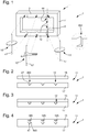
figure 1 représente, en perspective, une structure selon l'invention comportant un cadre monobloc indéformable qui comporte des logements alignés deux à deux formant pivots pour la réception d'extrémités d'arbres de mobiles pivotants ; - les
figures 2 et 3 illustrent en vue de dessus la coopération d'un couvercle avec ce cadre, respectivement en positions ouverte et fermée, pour immobiliser ces extrémités d'arbres, lafigure 4 illustrant une variante avantageuse de couvercle avec des lames flexibles de rattrapage de jeu ;
- la
figure 5 représente, de façon similaire à lafigure 1 , une variante où au moins un des mobiles pivotants montés dans la structure est pivoté au moins à une de ses extrémités dans un porte-palier relié au cadre monobloc par des moyens de rappel élastique intégrés, et blocable en position ; - la
figure 6 représente, en vue en plan, un tel ensemble monolithique comportant des moyens de réglage en position d'un porte-palier intégré à cette structure, ces moyens de réglage étant immobilisables en position par des moyens de blocage ; les moyens de réglage comportent un peigne immobilisant un index situé à l'extrémité d'une lame flexible, le peigne étant plaqué sur cet index par une lame-ressort de blocage elle-même immobilisée par un doigt de verrouillage ; - la
figure 7 représente une section passant par l'axe d'un pivot particulier avec un palier anti-chocs monobloc avec le cadre monobloc; - la
figure 8 est un schéma d'un mouvement d'horlogerie comportant une structure selon l'invention.
- the
figure 1 represents, in perspective, a structure according to the invention comprising a non-deformable monobloc frame which comprises pairs of housings aligned pivots for receiving ends of shafts of pivoting mobile; - the
Figures 2 and 3 illustrate in top view the cooperation of a cover with this frame, respectively in open and closed positions, to immobilize these tree ends, thefigure 4 illustrating an advantageous variant of the cover with flexible blades for catching play;
- the
figure 5 represents, similarly to thefigure 1 , a variant wherein at least one of the pivoting mobile members mounted in the structure is pivoted at least at one of its ends in a bearing carrier connected to the one-piece frame by integral elastic return means, and lockable in position; - the
figure 6 represents, in plan view, such a monolithic assembly comprising adjustment means in position of a bearing holder integrated in this structure, these adjustment means being immobilizable in position by locking means; the adjustment means comprise a comb immobilizing an index located at the end of a flexible blade, the comb being pressed on this index by a locking spring blade itself immobilized by a locking finger; - the
figure 7 represents a section passing through the axis of a particular pivot with a one-piece shock-absorbing bearing with the one-piece frame; - the
figure 8 is a diagram of a clockwork movement comprising a structure according to the invention.
L'invention concerne le domaine des mécanismes d'horlogerie, et plus particulièrement des mouvements intégrant des modules fonctionnels prêts à l'emploi.The invention relates to the field of watch mechanisms, and more particularly to movements incorporating ready-to-use functional modules.
L'invention concerne une structure 1 de mécanisme d'horlogerie pour la réception et le guidage d'au moins un mobile pivotant 10, comportant au moins un arbre 47 comportant des guidages en pivotement, naturellement un tel mobile 10 peut aussi comporter uniquement des guidages d'extrémité, sans partie arbrée sur toute sa longueur, la présente description utilise toutefois la dénomination « arbre 47 » par souci de simplification, pour désigner les guidages ou pivots que comporte le mobile pivotant 10..The invention relates to a
Selon l'invention, cette structure 1 comporte au moins une structure monobloc indémontable 11, laquelle comporte des points de pivotement 12 alignés deux à deux pour la réception de pivots d'au moins un tel mobile pivotant 10.According to the invention, this
La description est volontairement restreinte, dans un souci de concision, à ce cas particulier préféré de guidage en pivotement de mobiles pivotants. L'homme du métier comprendra l'intérêt de l'invention pour d'autres applications, en particulier pour immobiliser des composants non pivotants prisonniers dans une structure indéformable.The description is deliberately restricted, for the sake of brevity, to this particular preferred case of pivotal guidance of pivoting mobiles. Those skilled in the art will understand the interest of the invention for other applications, in particular particularly for immobilizing non-pivoting components trapped in a dimensionally stable structure.
Dans une réalisation préférée, tel que visible sur les figures, cette structure monobloc indémontable 11 comporte au moins un cadre 17 monobloc indémontable, qui comporte, au niveau de logements 460, notamment un palier supérieur 44 et un palier inférieur 45, des points de pivotement 12 alignés deux à deux pour la réception de pivots d'au moins un tel mobile pivotant 10.In a preferred embodiment, as can be seen in the figures, this unbreakable
De préférence, cet au moins un cadre 17 monobloc indéformable comporte, à tout ou partie de ces points de pivotement 12, des logements 460 alignés deux à deux à chaque fois pour la réception d'un arbre 47 d'un tel mobile pivotant 10.Preferably, this at least one undeformable one-
Dans la réalisation avantageuse des
Dans une version particulière, au moins un tel couvercle 18 est réalisé de façon monobloc avec un tel cadre 17, auquel il est relié par une fixation flexible, et sur lequel il est rabattu après insertion du ou des mobiles pivotants 10, ou similaire.In a particular version, at least one
De façon avantageuse, le couvercle 18 est fixé de façon irréversible sur le cadre 17, par soudage, brasage, soudage laser, collage, rivetage, ou autre, pour constituer la structure 11 monobloc indémontable, après le montage des mobiles pivotants 10.Advantageously, the
Dans une réalisation particulière, non illustrée, la structure 1 incorpore une platine ou/et au moins un pont, constituant le cadre 17 ou y étant rattaché(e) de façon indémontable. Le cadre 17 peut aussi être indépendant de la platine et du pont, et être fixé sur l'un ou l'autre des deux, ou sur les deux à la fois.In a particular embodiment, not illustrated, the
De façon avantageuse, la structure 1 comporte des moyens flexibles 18A de rattrapage de jeu, pour enfermer sans jeu chaque tel arbre 47 de chaque tel mobile pivotant 10 que comporte la cassette 1. La
La
Dans une variante non illustrée, la portée de révolution 46 ou la portée frontale 49 est portée par un amortisseur de choc qui lui est propre.In a variant not shown, the
Dans une variante non illustrée, la portée de révolution 46 et la portée frontale 49 sont portées séparément par un amortisseur de choc, lequel peut être commun avec deux surfaces d'appui, ou bien multiple, chaque portée étant portée par un amortisseur de choc qui lui est propre.In a variant not shown, the
Dans une variante particulière de réalisation, cet amortisseur de choc élastique 48 est monobloc avec le cadre 17.In a particular embodiment, this
Dans une autre variante particulière de réalisation, cette portée de révolution 46 ou/et cette portée frontale 49 est monobloc avec le cadre 17.In another particular embodiment, this range of
Dans encore une autre variante particulière de réalisation, cet amortisseur de choc élastique 48, cette portée de révolution 46 ou/et cette portée frontale 49, sont, ensemble, monobloc avec le cadre 17.In yet another particular embodiment, this
Dans une réalisation particulière, la structure monobloc indémontable 11 est réalisée en silicium, et les moyens de rappel élastique intrinsèques qu'elle comporte, si c'est le cas, sont précontraints dans un état oxydé du silicium.In a particular embodiment, the unbreakable
Dans une réalisation particulière, le cadre 17 est réalisé en silicium, et les moyens de rappel élastique intrinsèques qu'il comporte sont précontraints dans un état oxydé du silicium.In a particular embodiment, the
Les pivots 44, 45, peuvent être constitués par des pivots classiques ou par des guidages flexibles.The
La conception de structures 1 selon l'invention comportant des composants monobloc indémontables 17 permet, encore, d'optimiser les pivotements des différents mobiles, et, selon le besoin, d'en assurer le parallélisme, ou au contraire de déplacer au moins une extrémité d'un arbre de mobile pour modifier un réglage de façon micrométrique.The design of
L'action sur les points de pivotement permet, notamment, de régler les entraxes entre mobiles pour régler la pénétration des dentures ou/et levées. Le réglage de l'entraxe peut être réalisé de façon monolithique avec la platine ou le pont. Ce principe de réglage des entraxes est valable pour tous les entraxes dans un mouvement.The action on the pivot points allows, in particular, to adjust the distance between mobile to adjust the penetration of the teeth and / or lifted. Adjustment of the center distance can be achieved monolithically with the deck or bridge. This principle of adjustment of the distances is valid for all the distances in a movement.
Dans la réalisation particulière des
La
La variante dans laquelle un tel composant est pivoté à ses deux extrémités dans de tels porte-paliers suspendus, est naturellement aussi réalisable.The variant in which such a component is pivoted at both ends thereof in such suspended bearing supports is naturally also feasible.
Les moyens de rappel élastique 14 permettent une plage de réglage, de façon préférée, ils sont associés à des moyens de blocage en position après réglage, dont la présente description donne un exemple dans le cas particulier de la
Pour une application particulièrement intéressante à un mécanisme réglable et verrouillable, notamment de façon réversible, mais qui peut aussi être immobilisé (en particulier de façon irréversible) après un réglage initial, la structure 1 comporte, de préférence au niveau du cadre 17, un mécanisme réglable en position 80, tel que visible sur la
La
Ce mécanisme de verrouillage comporte au moins un élément flexible 98 faisant sautoir et fixé élastiquement à la structure 81, cet au moins un élément flexible 98 comporte ici un bec 99 qui coopère avec un bec 97 du bloqueur 94 pour maintenir le bloqueur écarté pendant le réglage en position, ou avec avec une surface d'arrêt complémentaire 95 du bloqueur 94 en sécurité du bloqueur quand le réglage en position est effectué.This locking mechanism comprises at least one
La
Comme on l'a vu plus haut, ce mécanisme combiné de réglage, blocage et verrouillage, illustré ici pour une application particulière de réglage d'une position de palier, par exemple pour effectuer une correction micrométrique sur la marche d'un mécanisme régulateur, est applicable à une grande diversité d'applications : positionnement d'un palier, d'une butée, ou autre.As has been seen above, this combined mechanism of adjustment, locking and locking, illustrated here for a particular application of adjustment of a bearing position, for example to perform a micrometric correction on the operation of a regulating mechanism, is applicable to a wide variety of applications: positioning a bearing, a stop, or other.
Dans une réalisation avantageuse, la structure 1, ou/et le cadre 17, est réalisée en silicium. Les points de pivotements des logements 460 sont définis, par exemple, par des gravures anisotropiques (KOH) dans un substrat silicium. Une version avec un assemblage des pierres ou des antichocs est également possible. Le gros avantage est le positionnement très précis des points de pivotement (entraxe, verticalité). On note que la pose du couvercle 18 ne perturbe pas le positionnement des différents arbres.In an advantageous embodiment, the
Pour une application particulière à un mécanisme d'échappement, selon sa configuration, la structure 1 incorpore tout ou partie des paliers de guidage des arbres des mobiles :
- les deux points de pivotement de l'ancre et l'ensemble des paliers inférieurs des autres mobiles ;
- les deux points de pivotement du balancier, et de l'ancre, et l'ensemble des paliers inférieurs des autres mobiles ;
- les deux points de pivotement du balancier et l'ensemble des paliers inférieurs des autres mobiles.
- the two pivot points of the anchor and the set of lower bearings of the other mobiles;
- the two points of pivoting of the balance, and of the anchor, and the set of lower bearings of the other mobiles;
- the two points of pivoting of the balance and the set of lower bearings of other mobiles.
Dans un mode de réalisation particulier de l'invention, le cadre 17 forme un composant monobloc indémontable avec au moins un palier antichocs pour la réception d'un pivot d'un composant du mécanisme incorporé dans la structure 1, notamment un mécanisme d'échappement.In a particular embodiment of the invention, the
Les anti-chocs peuvent ainsi être partiellement ou totalement réalisés dans le cadre 17 : le ressort de l'antichoc peut être réalisé en commun avec le cadre 17. Une des deux (ou les deux) pierres peut être réalisée en commun avec la platine. Le pivotement se fait alors directement dans le silicium. Les points de pivotements 12 peuvent être réalisés directement dans le silicium avec des revêtements de surface du type DLC ou autre. Il n'y a donc plus de pierre, et les points de rotation sont positionnés très précisément.The anti-shock can thus be partially or completely made in the frame 17: the spring of the shock can be made in common with the
Dans une réalisation particulière, la structure 1 comporte des éléments sécables, destinés à faciliter son assemblage dans un ensemble supérieur, il suffit de briser ensuite ces éléments sécables pour donner un ou plusieurs degrés de liberté à certains de ses constituants.In a particular embodiment, the
Dans une réalisation avantageuse de la cassette 1 selon l'invention, la structure 1 est réalisée en matériau micro-usinable, ou en silicium, ou en silicium oxydé, et les moyens de rappel élastique intrinsèques éventuels qu'elle comporte sont précontraints dans un état oxydé du silicium. D'autres matériaux selon les technologies MEMS ou « LIGA » peuvent être mis en oeuvre. Le quartz, le DLC, des matériaux au moins partiellement amorphes, des verres métalliques, peuvent, et non limitativement, être utilisés pour ces applications.In an advantageous embodiment of the
Une structuration particulière de la structure 1 peut permettre de compenser les effets de la dilatation de ces éléments de structure, ou des composants du mécanisme assemblé en combinaison avec elle. Il est par exemple possible de réaliser la platine en silicium, puis de l'oxyder, afin de travailler en cohérence.A particular structure of the
L'invention concerne encore un mouvement d'horlogerie 100 mécanique comportant au moins une telle structure 1.The invention also relates to a
La haute précision apportée par l'invention permet de réaliser un amincissement des composants, et donc du mouvement. L'invention est donc particulièrement utile pour la réalisation de mouvements extra-plats.The high precision provided by the invention makes it possible to thin the components, and therefore the movement. The invention is therefore particularly useful for performing ultra-thin movements.
Claims (12)
- Structure (1) for a timepiece mechanism for receiving and guiding at least one pivoting mobile component (10), said structure including at least one inseparable single-piece structure (11), which includes at least one inseparable single-piece frame (17) including pivot points (12) with housings (460) aligned in pairs in each case for receiving an arbor (47) of a said pivoting mobile component (10), characterized in that said structure (1) includes at least one cover (18) arranged to cooperate with said at least one frame (17) in order, in the closure position of said at least one cover (18) on said at least one frame (17), to confine with minimum play each said arbor (47) of each said pivoting mobile component (10) comprised in said structure (1), and characterized in that said structure (1) includes, on said at least one frame (17) and/or said at least one cover (18), flexible play take-up means (18A) for confining without play each said arbor (47) of each said pivoting mobile component (10) comprised in said structure (1).
- Structure (1) according to claim 1, characterized in that said cover (18) forms a single-piece assembly with said frame (17) to constitute said inseparable single-piece structure (11), after the mounting of said pivoting mobile components (10).
- Structure (1) according to claim 1 or 2, characterized in that at least one said housing (460) includes a shoulder of revolution (46) for radially holding an arbor (47) of a said pivoting mobile component (10), and a frontal shoulder (49) for axially limiting the end of said arbor (47), said shoulder of revolution (46) and/or said frontal shoulder (49) being carried by at least one resilient shock absorber (48).
- Structure (1) according to claim 3, characterized in that said resilient shock absorber (48) is in one piece with said frame (7).
- Structure (1) according to claim 3 or 4, characterized in that said frontal shoulder (49) is in one piece with said frame (7).
- Structure (1) according to any of the preceding claims, characterized in that at least one said housing (460) is integral with a bearing carrier (13) connected to said frame (17) by elastic return means (14).
- Structure (1) according to any of the preceding claims, characterized in that at least one said inseparable single-piece structure (11) comprises a position adjustable mechanism (80) including a rigid structure (81) carrying, via at least one resilient strip (83), a position adjustable component (82) including indexing means (84) arranged to cooperate with complementary indexing means (91) comprised in an adjustment mechanism (90), said complementary indexing means (91) being detachably mounted to the indexing means (84) and being lockable in a cooperating position by a clamping mechanism (94) resiliently secured to said structure (81), said clamping mechanism (94) being in turn subject to the action of a locking mechanism (98) which allows said clamping mechanism to occupy either a detached position wherein said adjustment mechanism (90) is free, or an engaged position wherein said clamping mechanism (94) hinders said adjustment mechanism (90), said locking mechanism (98) also being resiliently fixed to said structure (81).
- Mechanical timepiece movement (100) comprising at least one structure (1) according to any of the preceding claims.
- Method of forming a structure (1) for a timepiece mechanism according to any of claims 1 to 7, for receiving and guiding at least one pivoting mobile component (10) comprising an arbor (47), characterized in that said inseparable single-piece structure (11) is equipped with integrated elastic return means in a single-piece therewith, either for holding without play at least one said arbor (47) of at least one said pivoting mobile component (10), and/or for forming at least one resilient shock absorber (48), and/or for allowing adjustment of the position of a bearing carrier (13), and in that said inseparable single-piece structure (11) is made of silicon, and in that said integrated elastic return means comprised in said structure (1) is prestressed in an oxidised silicon state.
- Method according to the preceding claim, characterized in that said housings (460) are made directly in the silicon with DLC surface coatings.
- Method according to claim 9 or 10, characterized in that said inseparable single-piece structure (11) is made with at least one inseparable single-piece frame (17) including pivot points (12) with housings (460) aligned in pairs for receiving the pivots of at least one said pivoting mobile component (10), and in that said housings (460) are made by anisotropic etches in a silicon substrate.
- Method according to the preceding claim, characterized in that said inseparable single-piece structure (11) is formed with said frame (17) and a cover (18) together captively holding said pivoting mobile components (10) in position in said housings (460), and in that said frame (17) and said cover (18) are irreversibly secured to each other by welding or soldering or bonding or rivets or by laser welding to form an inseparable single-piece assembly.
Priority Applications (9)
| Application Number | Priority Date | Filing Date | Title |
|---|---|---|---|
| CH00630/13A CH707813A2 (en) | 2013-03-19 | 2013-03-19 | Structure clockwork mobile pivot. |
| EP13160027.2A EP2781971B1 (en) | 2013-03-19 | 2013-03-19 | Structure of a clockwork mechanism |
| TW103104730A TWI610154B (en) | 2013-03-19 | 2014-02-13 | Timepiece mechanism structure,method of forming the structure,and mechanical timepiece movement |
| EP14158656.0A EP2790070B1 (en) | 2013-03-19 | 2014-03-10 | Structure for a timepiece mechanism |
| US14/204,160 US9235191B2 (en) | 2013-03-19 | 2014-03-11 | Timepiece mechanism structure |
| JP2014054685A JP5798652B2 (en) | 2013-03-19 | 2014-03-18 | Clock mechanism |
| KR1020140031461A KR101545443B1 (en) | 2013-03-19 | 2014-03-18 | Timepiece mechanism structure |
| CN201410102917.2A CN104062888B (en) | 2013-03-19 | 2014-03-19 | Clockwork assembly |
| HK15102950.7A HK1202654A1 (en) | 2013-03-19 | 2015-03-23 | Timepiece mechanism structure |
Applications Claiming Priority (1)
| Application Number | Priority Date | Filing Date | Title |
|---|---|---|---|
| EP13160027.2A EP2781971B1 (en) | 2013-03-19 | 2013-03-19 | Structure of a clockwork mechanism |
Publications (2)
| Publication Number | Publication Date |
|---|---|
| EP2781971A1 EP2781971A1 (en) | 2014-09-24 |
| EP2781971B1 true EP2781971B1 (en) | 2017-11-08 |
Family
ID=47997064
Family Applications (2)
| Application Number | Title | Priority Date | Filing Date |
|---|---|---|---|
| EP13160027.2A Active EP2781971B1 (en) | 2013-03-19 | 2013-03-19 | Structure of a clockwork mechanism |
| EP14158656.0A Active EP2790070B1 (en) | 2013-03-19 | 2014-03-10 | Structure for a timepiece mechanism |
Family Applications After (1)
| Application Number | Title | Priority Date | Filing Date |
|---|---|---|---|
| EP14158656.0A Active EP2790070B1 (en) | 2013-03-19 | 2014-03-10 | Structure for a timepiece mechanism |
Country Status (8)
| Country | Link |
|---|---|
| US (1) | US9235191B2 (en) |
| EP (2) | EP2781971B1 (en) |
| JP (1) | JP5798652B2 (en) |
| KR (1) | KR101545443B1 (en) |
| CN (1) | CN104062888B (en) |
| CH (1) | CH707813A2 (en) |
| HK (1) | HK1202654A1 (en) |
| TW (1) | TWI610154B (en) |
Families Citing this family (3)
| Publication number | Priority date | Publication date | Assignee | Title |
|---|---|---|---|---|
| EP3382468B1 (en) * | 2017-03-30 | 2020-01-15 | The Swatch Group Research and Development Ltd | Movement with extension of running reserve |
| CH716957A2 (en) * | 2019-12-16 | 2021-06-30 | Eta Sa Mft Horlogere Suisse | Guidance device for clock display. |
| CN112718072B (en) * | 2020-12-09 | 2022-04-19 | 安徽华铂再生资源科技有限公司 | Crushing equipment for recycling waste lead storage batteries and working method thereof |
Family Cites Families (28)
| Publication number | Priority date | Publication date | Assignee | Title |
|---|---|---|---|---|
| NL11224C (en) * | ||||
| US580046A (en) * | 1897-04-06 | Watc h - plate | ||
| CH427657A (en) * | 1961-11-29 | 1966-09-15 | Parechoc Sa | Shock-absorbing bearing for watchmaking mobile |
| US3306028A (en) * | 1966-01-04 | 1967-02-28 | Citizen Watch Co Ltd | Shock-proof device for watches |
| CH488169A (en) * | 1968-02-26 | 1970-03-31 | Lapanouse Montres Rego S A R | Pivoting device for compass needle |
| US3582162A (en) * | 1969-11-03 | 1971-06-01 | Max Baermann | Temperature compensated permanent magnet bearing |
| JPS513002Y1 (en) * | 1970-12-28 | 1976-01-28 | ||
| CH1052871A4 (en) * | 1971-07-15 | 1974-09-13 | ||
| DE2218663C3 (en) * | 1972-04-18 | 1978-04-20 | Fa. Mueller-Schlenker, 7220 Schwenningen | Bearing arrangement for balance with vertical shaft |
| CH495673A4 (en) * | 1973-04-06 | 1976-10-29 | Seitz Sa | Device for pivoting the face of a timepiece mobile |
| JPS5149063U (en) * | 1974-10-11 | 1976-04-13 | ||
| JPS5149063A (en) | 1974-10-24 | 1976-04-27 | Suwa Seikosha Kk | |
| JPS5239167U (en) * | 1975-09-10 | 1977-03-19 | ||
| JPS6288983U (en) * | 1985-11-25 | 1987-06-06 | ||
| US5416752A (en) * | 1987-07-21 | 1995-05-16 | Seiko Epson Corporation | Timepiece |
| US5369627A (en) * | 1987-07-21 | 1994-11-29 | Seiko Epson Corporation | Improvements in bearing and frame structure of a timepiece |
| EP1119317A1 (en) | 1998-09-30 | 2001-08-01 | Bionx Implants Oy | Chute for endosteal ligament fixation |
| JP2001281013A (en) * | 2000-03-30 | 2001-10-10 | Denso Corp | Indicating instrument |
| US6755566B2 (en) * | 2001-02-15 | 2004-06-29 | Konrad Damasko | Clockwork |
| EP1696286B1 (en) * | 2005-02-23 | 2010-12-29 | ETA SA Manufacture Horlogère Suisse | Shock-damping bearing for timepieces |
| DE602005006731D1 (en) * | 2005-03-23 | 2008-06-26 | Rolex Sa | Shock-absorbing storage for watches |
| JP4992319B2 (en) * | 2006-07-10 | 2012-08-08 | セイコーエプソン株式会社 | clock |
| EP1986059A1 (en) * | 2007-04-26 | 2008-10-29 | ETA SA Manufacture Horlogère Suisse | Pivoting device for an arbor inside a timepiece |
| EP2060957A1 (en) | 2007-11-16 | 2009-05-20 | ETA SA Manufacture Horlogère Suisse | Motor element with springs for timepiece movement |
| CN103124935B (en) * | 2010-06-22 | 2015-05-13 | 斯沃奇集团研究和开发有限公司 | Timepiece anti-shock system |
| EP2410386B1 (en) | 2010-07-19 | 2018-10-03 | Nivarox-FAR S.A. | balance wheel with inertia adjustment with insert |
| EP2605079B1 (en) | 2011-12-13 | 2014-10-01 | ETA SA Manufacture Horlogère Suisse | Modular clock movement with functional modules |
| EP2605087B1 (en) | 2011-12-13 | 2017-07-26 | ETA SA Manufacture Horlogère Suisse | Modular clock assembly with functional modules |
-
2013
- 2013-03-19 EP EP13160027.2A patent/EP2781971B1/en active Active
- 2013-03-19 CH CH00630/13A patent/CH707813A2/en not_active Application Discontinuation
-
2014
- 2014-02-13 TW TW103104730A patent/TWI610154B/en active
- 2014-03-10 EP EP14158656.0A patent/EP2790070B1/en active Active
- 2014-03-11 US US14/204,160 patent/US9235191B2/en active Active
- 2014-03-18 JP JP2014054685A patent/JP5798652B2/en active Active
- 2014-03-18 KR KR1020140031461A patent/KR101545443B1/en active IP Right Grant
- 2014-03-19 CN CN201410102917.2A patent/CN104062888B/en active Active
-
2015
- 2015-03-23 HK HK15102950.7A patent/HK1202654A1/en unknown
Non-Patent Citations (1)
| Title |
|---|
| None * |
Also Published As
| Publication number | Publication date |
|---|---|
| TWI610154B (en) | 2018-01-01 |
| CN104062888B (en) | 2017-03-01 |
| US9235191B2 (en) | 2016-01-12 |
| HK1202654A1 (en) | 2015-10-02 |
| EP2790070B1 (en) | 2017-11-15 |
| TW201500868A (en) | 2015-01-01 |
| US20140286139A1 (en) | 2014-09-25 |
| CH707813A2 (en) | 2014-09-30 |
| EP2790070A3 (en) | 2016-06-22 |
| JP5798652B2 (en) | 2015-10-21 |
| CN104062888A (en) | 2014-09-24 |
| EP2790070A2 (en) | 2014-10-15 |
| JP2014182145A (en) | 2014-09-29 |
| KR101545443B1 (en) | 2015-08-18 |
| EP2781971A1 (en) | 2014-09-24 |
| KR20140114782A (en) | 2014-09-29 |
Similar Documents
| Publication | Publication Date | Title |
|---|---|---|
| EP3356690B1 (en) | Mechanical component with flexible pivot, in particular for clockmaking | |
| EP2781970B1 (en) | Mechanism for adjusting a timepice hairspring | |
| EP2781967B1 (en) | Timepiece hairspring | |
| EP2790066B1 (en) | Frame for a clockwork | |
| EP3172626B1 (en) | Pivot with blade | |
| EP2690507B1 (en) | Holorological hairspring | |
| EP2781969B1 (en) | Non-removable one-piece timepiece component | |
| EP2976684B1 (en) | Pivot for clock mechanism | |
| EP2781971B1 (en) | Structure of a clockwork mechanism | |
| EP2948820B1 (en) | Device for guiding a clockwork arbor | |
| EP2466397A1 (en) | Rotating clock component with peripheral guide | |
| EP3163384B1 (en) | Flexible pivoting guide of a clock mobile | |
| CH708280A2 (en) | micrometer mobile watchmaker frolic setting. | |
| EP3839651A1 (en) | Mechanical timepiece oscillator with flexible guide | |
| EP3714336B1 (en) | Support of a mobile holding a display disc | |
| EP2976682B1 (en) | Anchor for horological escapement | |
| CH706108B1 (en) | Simplified stop-seconds device for watch movement. | |
| CH707810A2 (en) | intermittent locking mechanism, such as an anchor for watches escape mechanism. | |
| CH714318A2 (en) | Clockwork motor member delivering a substantially constant force. | |
| CH706763A2 (en) | Clockmaker assembly for clockwork of timepiece, has stud and/or shell comprising brake unit that is attached with coil of turns when accelerating contraction or extension of spring is higher than set value so as to change spring stiffness |
Legal Events
| Date | Code | Title | Description |
|---|---|---|---|
| PUAI | Public reference made under article 153(3) epc to a published international application that has entered the european phase |
Free format text: ORIGINAL CODE: 0009012 |
|
| 17P | Request for examination filed |
Effective date: 20130319 |
|
| AK | Designated contracting states |
Kind code of ref document: A1 Designated state(s): AL AT BE BG CH CY CZ DE DK EE ES FI FR GB GR HR HU IE IS IT LI LT LU LV MC MK MT NL NO PL PT RO RS SE SI SK SM TR |
|
| AX | Request for extension of the european patent |
Extension state: BA ME |
|
| R17P | Request for examination filed (corrected) |
Effective date: 20150120 |
|
| RBV | Designated contracting states (corrected) |
Designated state(s): AL AT BE BG CH CY CZ DE DK EE ES FI FR GB GR HR HU IE IS IT LI LT LU LV MC MK MT NL NO PL PT RO RS SE SI SK SM TR |
|
| RIC1 | Information provided on ipc code assigned before grant |
Ipc: G04B 15/14 20060101ALI20170524BHEP Ipc: G04B 31/00 20060101ALI20170524BHEP Ipc: G04B 29/00 20060101AFI20170524BHEP |
|
| GRAP | Despatch of communication of intention to grant a patent |
Free format text: ORIGINAL CODE: EPIDOSNIGR1 |
|
| INTG | Intention to grant announced |
Effective date: 20170629 |
|
| GRAS | Grant fee paid |
Free format text: ORIGINAL CODE: EPIDOSNIGR3 |
|
| GRAA | (expected) grant |
Free format text: ORIGINAL CODE: 0009210 |
|
| AK | Designated contracting states |
Kind code of ref document: B1 Designated state(s): AL AT BE BG CH CY CZ DE DK EE ES FI FR GB GR HR HU IE IS IT LI LT LU LV MC MK MT NL NO PL PT RO RS SE SI SK SM TR |
|
| REG | Reference to a national code |
Ref country code: GB Ref legal event code: FG4D Free format text: NOT ENGLISH |
|
| REG | Reference to a national code |
Ref country code: CH Ref legal event code: EP Ref country code: CH Ref legal event code: NV Representative=s name: ICB INGENIEURS CONSEILS EN BREVETS SA, CH Ref country code: AT Ref legal event code: REF Ref document number: 944727 Country of ref document: AT Kind code of ref document: T Effective date: 20171115 |
|
| REG | Reference to a national code |
Ref country code: IE Ref legal event code: FG4D Free format text: LANGUAGE OF EP DOCUMENT: FRENCH |
|
| REG | Reference to a national code |
Ref country code: DE Ref legal event code: R096 Ref document number: 602013028994 Country of ref document: DE |
|
| REG | Reference to a national code |
Ref country code: FR Ref legal event code: PLFP Year of fee payment: 6 |
|
| REG | Reference to a national code |
Ref country code: NL Ref legal event code: MP Effective date: 20171108 |
|
| REG | Reference to a national code |
Ref country code: LT Ref legal event code: MG4D |
|
| REG | Reference to a national code |
Ref country code: AT Ref legal event code: MK05 Ref document number: 944727 Country of ref document: AT Kind code of ref document: T Effective date: 20171108 |
|
| PG25 | Lapsed in a contracting state [announced via postgrant information from national office to epo] |
Ref country code: LT Free format text: LAPSE BECAUSE OF FAILURE TO SUBMIT A TRANSLATION OF THE DESCRIPTION OR TO PAY THE FEE WITHIN THE PRESCRIBED TIME-LIMIT Effective date: 20171108 Ref country code: FI Free format text: LAPSE BECAUSE OF FAILURE TO SUBMIT A TRANSLATION OF THE DESCRIPTION OR TO PAY THE FEE WITHIN THE PRESCRIBED TIME-LIMIT Effective date: 20171108 Ref country code: NL Free format text: LAPSE BECAUSE OF FAILURE TO SUBMIT A TRANSLATION OF THE DESCRIPTION OR TO PAY THE FEE WITHIN THE PRESCRIBED TIME-LIMIT Effective date: 20171108 Ref country code: NO Free format text: LAPSE BECAUSE OF FAILURE TO SUBMIT A TRANSLATION OF THE DESCRIPTION OR TO PAY THE FEE WITHIN THE PRESCRIBED TIME-LIMIT Effective date: 20180208 Ref country code: SE Free format text: LAPSE BECAUSE OF FAILURE TO SUBMIT A TRANSLATION OF THE DESCRIPTION OR TO PAY THE FEE WITHIN THE PRESCRIBED TIME-LIMIT Effective date: 20171108 Ref country code: ES Free format text: LAPSE BECAUSE OF FAILURE TO SUBMIT A TRANSLATION OF THE DESCRIPTION OR TO PAY THE FEE WITHIN THE PRESCRIBED TIME-LIMIT Effective date: 20171108 |
|
| PG25 | Lapsed in a contracting state [announced via postgrant information from national office to epo] |
Ref country code: HR Free format text: LAPSE BECAUSE OF FAILURE TO SUBMIT A TRANSLATION OF THE DESCRIPTION OR TO PAY THE FEE WITHIN THE PRESCRIBED TIME-LIMIT Effective date: 20171108 Ref country code: RS Free format text: LAPSE BECAUSE OF FAILURE TO SUBMIT A TRANSLATION OF THE DESCRIPTION OR TO PAY THE FEE WITHIN THE PRESCRIBED TIME-LIMIT Effective date: 20171108 Ref country code: GR Free format text: LAPSE BECAUSE OF FAILURE TO SUBMIT A TRANSLATION OF THE DESCRIPTION OR TO PAY THE FEE WITHIN THE PRESCRIBED TIME-LIMIT Effective date: 20180209 Ref country code: AT Free format text: LAPSE BECAUSE OF FAILURE TO SUBMIT A TRANSLATION OF THE DESCRIPTION OR TO PAY THE FEE WITHIN THE PRESCRIBED TIME-LIMIT Effective date: 20171108 Ref country code: LV Free format text: LAPSE BECAUSE OF FAILURE TO SUBMIT A TRANSLATION OF THE DESCRIPTION OR TO PAY THE FEE WITHIN THE PRESCRIBED TIME-LIMIT Effective date: 20171108 Ref country code: IS Free format text: LAPSE BECAUSE OF FAILURE TO SUBMIT A TRANSLATION OF THE DESCRIPTION OR TO PAY THE FEE WITHIN THE PRESCRIBED TIME-LIMIT Effective date: 20180308 Ref country code: BG Free format text: LAPSE BECAUSE OF FAILURE TO SUBMIT A TRANSLATION OF THE DESCRIPTION OR TO PAY THE FEE WITHIN THE PRESCRIBED TIME-LIMIT Effective date: 20180208 |
|
| PG25 | Lapsed in a contracting state [announced via postgrant information from national office to epo] |
Ref country code: SK Free format text: LAPSE BECAUSE OF FAILURE TO SUBMIT A TRANSLATION OF THE DESCRIPTION OR TO PAY THE FEE WITHIN THE PRESCRIBED TIME-LIMIT Effective date: 20171108 Ref country code: CZ Free format text: LAPSE BECAUSE OF FAILURE TO SUBMIT A TRANSLATION OF THE DESCRIPTION OR TO PAY THE FEE WITHIN THE PRESCRIBED TIME-LIMIT Effective date: 20171108 Ref country code: DK Free format text: LAPSE BECAUSE OF FAILURE TO SUBMIT A TRANSLATION OF THE DESCRIPTION OR TO PAY THE FEE WITHIN THE PRESCRIBED TIME-LIMIT Effective date: 20171108 Ref country code: CY Free format text: LAPSE BECAUSE OF FAILURE TO SUBMIT A TRANSLATION OF THE DESCRIPTION OR TO PAY THE FEE WITHIN THE PRESCRIBED TIME-LIMIT Effective date: 20171108 Ref country code: EE Free format text: LAPSE BECAUSE OF FAILURE TO SUBMIT A TRANSLATION OF THE DESCRIPTION OR TO PAY THE FEE WITHIN THE PRESCRIBED TIME-LIMIT Effective date: 20171108 |
|
| REG | Reference to a national code |
Ref country code: DE Ref legal event code: R097 Ref document number: 602013028994 Country of ref document: DE |
|
| PG25 | Lapsed in a contracting state [announced via postgrant information from national office to epo] |
Ref country code: SM Free format text: LAPSE BECAUSE OF FAILURE TO SUBMIT A TRANSLATION OF THE DESCRIPTION OR TO PAY THE FEE WITHIN THE PRESCRIBED TIME-LIMIT Effective date: 20171108 Ref country code: PL Free format text: LAPSE BECAUSE OF FAILURE TO SUBMIT A TRANSLATION OF THE DESCRIPTION OR TO PAY THE FEE WITHIN THE PRESCRIBED TIME-LIMIT Effective date: 20171108 Ref country code: RO Free format text: LAPSE BECAUSE OF FAILURE TO SUBMIT A TRANSLATION OF THE DESCRIPTION OR TO PAY THE FEE WITHIN THE PRESCRIBED TIME-LIMIT Effective date: 20171108 Ref country code: IT Free format text: LAPSE BECAUSE OF FAILURE TO SUBMIT A TRANSLATION OF THE DESCRIPTION OR TO PAY THE FEE WITHIN THE PRESCRIBED TIME-LIMIT Effective date: 20171108 |
|
| PLBE | No opposition filed within time limit |
Free format text: ORIGINAL CODE: 0009261 |
|
| STAA | Information on the status of an ep patent application or granted ep patent |
Free format text: STATUS: NO OPPOSITION FILED WITHIN TIME LIMIT |
|
| PG25 | Lapsed in a contracting state [announced via postgrant information from national office to epo] |
Ref country code: MT Free format text: LAPSE BECAUSE OF FAILURE TO SUBMIT A TRANSLATION OF THE DESCRIPTION OR TO PAY THE FEE WITHIN THE PRESCRIBED TIME-LIMIT Effective date: 20171108 |
|
| 26N | No opposition filed |
Effective date: 20180809 |
|
| PG25 | Lapsed in a contracting state [announced via postgrant information from national office to epo] |
Ref country code: SI Free format text: LAPSE BECAUSE OF FAILURE TO SUBMIT A TRANSLATION OF THE DESCRIPTION OR TO PAY THE FEE WITHIN THE PRESCRIBED TIME-LIMIT Effective date: 20171108 Ref country code: MC Free format text: LAPSE BECAUSE OF FAILURE TO SUBMIT A TRANSLATION OF THE DESCRIPTION OR TO PAY THE FEE WITHIN THE PRESCRIBED TIME-LIMIT Effective date: 20171108 |
|
| REG | Reference to a national code |
Ref country code: BE Ref legal event code: MM Effective date: 20180331 |
|
| REG | Reference to a national code |
Ref country code: IE Ref legal event code: MM4A |
|
| PG25 | Lapsed in a contracting state [announced via postgrant information from national office to epo] |
Ref country code: LU Free format text: LAPSE BECAUSE OF NON-PAYMENT OF DUE FEES Effective date: 20180319 |
|
| PG25 | Lapsed in a contracting state [announced via postgrant information from national office to epo] |
Ref country code: IE Free format text: LAPSE BECAUSE OF NON-PAYMENT OF DUE FEES Effective date: 20180319 |
|
| PG25 | Lapsed in a contracting state [announced via postgrant information from national office to epo] |
Ref country code: BE Free format text: LAPSE BECAUSE OF NON-PAYMENT OF DUE FEES Effective date: 20180331 |
|
| PG25 | Lapsed in a contracting state [announced via postgrant information from national office to epo] |
Ref country code: TR Free format text: LAPSE BECAUSE OF FAILURE TO SUBMIT A TRANSLATION OF THE DESCRIPTION OR TO PAY THE FEE WITHIN THE PRESCRIBED TIME-LIMIT Effective date: 20171108 |
|
| PG25 | Lapsed in a contracting state [announced via postgrant information from national office to epo] |
Ref country code: HU Free format text: LAPSE BECAUSE OF FAILURE TO SUBMIT A TRANSLATION OF THE DESCRIPTION OR TO PAY THE FEE WITHIN THE PRESCRIBED TIME-LIMIT; INVALID AB INITIO Effective date: 20130319 Ref country code: PT Free format text: LAPSE BECAUSE OF FAILURE TO SUBMIT A TRANSLATION OF THE DESCRIPTION OR TO PAY THE FEE WITHIN THE PRESCRIBED TIME-LIMIT Effective date: 20171108 |
|
| PG25 | Lapsed in a contracting state [announced via postgrant information from national office to epo] |
Ref country code: MK Free format text: LAPSE BECAUSE OF NON-PAYMENT OF DUE FEES Effective date: 20171108 |
|
| PG25 | Lapsed in a contracting state [announced via postgrant information from national office to epo] |
Ref country code: AL Free format text: LAPSE BECAUSE OF FAILURE TO SUBMIT A TRANSLATION OF THE DESCRIPTION OR TO PAY THE FEE WITHIN THE PRESCRIBED TIME-LIMIT Effective date: 20171108 |
|
| PGFP | Annual fee paid to national office [announced via postgrant information from national office to epo] |
Ref country code: FR Payment date: 20230222 Year of fee payment: 11 |
|
| PGFP | Annual fee paid to national office [announced via postgrant information from national office to epo] |
Ref country code: GB Payment date: 20230222 Year of fee payment: 11 Ref country code: DE Payment date: 20230221 Year of fee payment: 11 |
|
| P01 | Opt-out of the competence of the unified patent court (upc) registered |
Effective date: 20230611 |
|
| PGFP | Annual fee paid to national office [announced via postgrant information from national office to epo] |
Ref country code: CH Payment date: 20230402 Year of fee payment: 11 |