EP3671022A1 - Automotive lighting device and method for controlling an element thereof - Google Patents
Automotive lighting device and method for controlling an element thereof Download PDFInfo
- Publication number
- EP3671022A1 EP3671022A1 EP18214731.4A EP18214731A EP3671022A1 EP 3671022 A1 EP3671022 A1 EP 3671022A1 EP 18214731 A EP18214731 A EP 18214731A EP 3671022 A1 EP3671022 A1 EP 3671022A1
- Authority
- EP
- European Patent Office
- Prior art keywords
- lighting device
- driver
- housing
- hatch
- automotive lighting
- Prior art date
- Legal status (The legal status is an assumption and is not a legal conclusion. Google has not performed a legal analysis and makes no representation as to the accuracy of the status listed.)
- Granted
Links
Images

Classifications
-
- F—MECHANICAL ENGINEERING; LIGHTING; HEATING; WEAPONS; BLASTING
- F21—LIGHTING
- F21S—NON-PORTABLE LIGHTING DEVICES; SYSTEMS THEREOF; VEHICLE LIGHTING DEVICES SPECIALLY ADAPTED FOR VEHICLE EXTERIORS
- F21S45/00—Arrangements within vehicle lighting devices specially adapted for vehicle exteriors, for purposes other than emission or distribution of light
- F21S45/30—Ventilation or drainage of lighting devices
- F21S45/33—Ventilation or drainage of lighting devices specially adapted for headlamps
-
- F—MECHANICAL ENGINEERING; LIGHTING; HEATING; WEAPONS; BLASTING
- F21—LIGHTING
- F21S—NON-PORTABLE LIGHTING DEVICES; SYSTEMS THEREOF; VEHICLE LIGHTING DEVICES SPECIALLY ADAPTED FOR VEHICLE EXTERIORS
- F21S45/00—Arrangements within vehicle lighting devices specially adapted for vehicle exteriors, for purposes other than emission or distribution of light
- F21S45/40—Cooling of lighting devices
- F21S45/47—Passive cooling, e.g. using fins, thermal conductive elements or openings
Definitions
- the present invention belongs to the field of lamps for automotive vehicles, and more specifically, to the design of headlamps to avoid fogging in the outer glass.
- the invention provides an automotive lighting device comprising
- the desiccant salt does not need a dedicated heat source to release the moisture, but the driver which is used to manage the operation of the light source generates enough heat to activate the desiccant salt and cause the desorption of the humidity.
- the desiccant salt is arranged in direct contact with the driver cover.
- Direct contact between the salt and the driver cover allows a better transfer of the heat generated by the driver, thus increasing the drying rate.
- the driver is located in contact with the housing wall.
- This location allows the desiccant salt to be also close to the housing wall and to the ventilation elements, so that the humidity may exit the housing quickly after being released by the salt.
- the driver comprises a heatsink arranged to cover a hole in the housing.
- This location ensures an easy replacement of the driver and/or the salt, and reduces the space dedicated to this drying element.
- the automotive lighting device comprises more than one driver which are grouped in a driver assembly which comprises a protrusion.
- a driver assembly has a greater heat exchange surface, so that the desiccant salt may be distributed on the assembly to increase the desiccant amount, thus increasing the drying rate.
- the ventilation element comprises a porous material configured to allow water vapour to exit the housing but prevents liquid water to enter the housing.
- This configuration provides a watertight housing, which is useful for some lighting device which must fulfil this type of requirements.
- one ventilation element with the porous material is arranged in the bottom part of the housing and the desiccant salt is arranged in contact or at less than 1 cm from the driver cover.
- the temperature is theoretically lower, so the air is drier.
- the humidity rate will increase in the zone surrounding the desiccant salt.
- the humidity rate is lower in the engine compartment surrounding the housing, there will be a higher driving force for diffusion from the desiccant zone to the outside of the housing.
- the automotive lighting device further comprises channels to dissipate water vapour, wherein the channels are located in the side parts of the protrusion.
- the separating element is a hatch with an actuator, the actuator being controlled by the driver.
- the hatch is a good element to avoid the water vapour being sent back to the interior of the housing when the desiccant salt is activated by heat.
- the desiccant salt is one of silica gel, molecular sieves or activated alumina.
- desiccant salt which are useful to trap the vapour molecules and then release them when it is heated.
- the driver is arranged vertically.
- a vertical location makes it easy for the driver to be part of a vertical heatsink.
- the invention provides a method of controlling the operation of a separating element comprised in an automotive lighting device according to the first inventive aspect, the method comprising the step of opening the hatch when the lighting device is not being operated.
- the method further comprises the steps of closing the hatch when the lighting device is starting operation and following a pattern of opening and closing the hatch depending on the speed of an automotive vehicle where the lighting device is installed.
- a pattern depending on the vehicle speed may take advantage of natural convection cooling due to air speed.
- the hatch may be open to catch the humidity inside the headlamp.
- the hatch is closed to expel de humidity.
- the method further comprises the steps of closing the hatch when the lighting device is starting operation and following a pattern of opening and closing the hatch depending on the ambient temperature.
- the method further comprises the steps of closing the hatch when the lighting device is starting operation and following a pattern of opening and closing the hatch according to a predetermined cycle.
- the light source is a solid-state light source.
- solid state refers to light emitted by solid-state electroluminescence, which uses semiconductors to convert electricity into light. Compared to incandescent lighting, solid state lighting creates visible light with reduced heat generation and less energy dissipation.
- the typically small mass of a solid-state electronic lighting device provides for greater resistance to shock and vibration compared to brittle glass tubes/bulbs and long, thin filament wires. They also eliminate filament evaporation, potentially increasing the life span of the illumination device.
- Some examples of these types of lighting comprise semiconductor light-emitting diodes (LEDs), organic light-emitting diodes (OLED), or polymer light-emitting diodes (PLED) as sources of illumination rather than electrical filaments, plasma or gas.
- FIG. 1 shows a scheme of an automotive lighting device 1 according to the invention in a first operation mode.
- This lighting device comprises the following elements:
- the driver assembly comprises a driver cover 3 arranged to dissipate the heat generated by the driver assembly.
- a driver cover 3 arranged to dissipate the heat generated by the driver assembly.
- it is a metallic layer with a good thermal conductivity, which transfers the heat generated in the driver to the desiccant salt 6 which is located in direct contact with this cover 3. It could be also made of plastic conductive material.
- the ventilation elements 5 are configured to allow water vapour to exit the housing 4. It is a porous membrane, so that water vapour is allowed from the housing to the exterior but liquid water may not enter.
- the hatch 7 is provided between the desiccant salt 6 and the light source 2, to separate the interior of the housing in two regions, one small region at one side of the hatch 7, which comprises the driver assembly and the desiccant salt 6, and another region which is the rest of the lighting device, comprising the lighting source and the optical and thermal elements.
- the driver assembly also comprises a heatsink 8 arranged to cover a hole in the housing 4. In other embodiments, it is located in contact with the housing wall, so that the region with the driver assembly and the desiccant salt is limited.
- the driver assembly comprises a protrusion, to maximize the contact surface between the driver cover 3 and the desiccant salt 6, thus improving the drying rate.
- the opening and closing movements of the hatch 7 are driven by an actuator, which is controlled by a dedicated micro-controller. In other embodiments, it is the driver assembly which controls this operations
- the hatch is open, and therefore the water vapour particles may accede to the zone of the lighting device where the desiccant salt 6 is.
- the desiccant salt 6 is configured to absorb these particles, so that the humidity inside of the lighting device decreases, and the risk of mist decreases as well.
- Figure 2 shows this lighting device 1 in a second position, where the hatch 7 is closed and the desiccant salt 6 is expelling the vapour particles to the exterior of the lighting device through the ventilation means.
- Some vapour particles exit through the upper ventilation element by convection because they are hotter than the air outside the lighting device, and some of the vapour particles exit the lighting device through the lower ventilation element by diffusion, since the air outside the lighting device is drier in this zone.
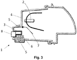
- Figure 3 shows an alternative arrangement of the element of this lighting device 1.
- the driver assembly has a different shape and the desiccant salt is located in the lower portion of the housing.
- the desiccant salt is arranged in contact or at less than 1 cm from the driver cover.
- the hatch may be controlled according to many different strategies.
- the hatch may be open, so that the salt may absorb humidity.
- a pattern depending on the vehicle speed may take advantage of natural convection cooling due to air speed.
- the hatch may be open to catch the humidity inside the headlamp.
- the hatch is closed to expel de humidity.
- this pattern may also depend on ambient conditions. For example, at rapid drop of external temperature, it is more advantageous to open the hatch to catch the humidity inside the headlamp, since the external temperature also affects the temperature inside the housing.
- a predetermined cycle may also be used, without taking into account either the humidity or the car speed conditions. This is a cheaper way of controlling, but it is less efficient.
Landscapes
- Engineering & Computer Science (AREA)
- General Engineering & Computer Science (AREA)
- Non-Portable Lighting Devices Or Systems Thereof (AREA)
- Arrangements Of Lighting Devices For Vehicle Interiors, Mounting And Supporting Thereof, Circuits Therefore (AREA)
- Arrangement Of Elements, Cooling, Sealing, Or The Like Of Lighting Devices (AREA)
Abstract
Description
- The present invention belongs to the field of lamps for automotive vehicles, and more specifically, to the design of headlamps to avoid fogging in the outer glass.
- Current headlamps have to fulfil different requirements which sometimes involve contradictory design paths. One example of this is related to demisting problems.
- Misting is caused when water vapour condenses on the internal surface of a glass. Micro-drops are unaesthetic and affect the light behaviour, so great efforts are put to solve this problem. However, in order to design modern and efficient lighting devices, walls of opaque materials must surround the light source, to avoid light leakage. But these opaque walls are an obstacle for a free path of dry air to reach the glass surface and avoid condensation.
- Hence, the better a solution is for avoiding light leakage, the worse for avoiding glass condensation because these opaque walls create a tortuous defogging air path that will have a very low flow rate and, consequently, a very slow defogging velocity.
- Some solutions use a desiccant salt which absorbs moisture in the interior of the housing and then is heated to evacuate this water vapour outside the housing. Examples are found in
US 2016/363331 A1 , which discloses a device for removing moisture from the interior of a housing. - The invention provides a solution for this problem by the provision of an automotive lighting device according to
claim 1. Preferred embodiments of the invention are defined in dependent claims. - Unless otherwise defined, all terms (including technical and scientific terms) used herein are to be interpreted as is customary in the art. It will be further understood that terms in common usage should also be interpreted as is customary in the relevant art and not in an idealised or overly formal sense unless expressly so defined herein.
- In this text, the term "comprises" and its derivations (such as "comprising", etc.) should not be understood in an excluding sense, that is, these terms should not be interpreted as excluding the possibility that what is described and defined may include further elements, steps, etc.
- In a first inventive aspect, the invention provides an automotive lighting device comprising
- a light source intended to emit light;
- a driver arranged to control the operation of the light source, the driver comprising a driver cover arranged to dissipate the heat generated by the driver;
- a housing comprising a housing wall and a ventilation element located in the housing wall, the ventilation element being configured to allow water vapour to exit the housing;
- a desiccant salt arranged in thermal contact with the driver cover;
- a separating element provided between the desiccant salt and the light source.
- The desiccant salt does not need a dedicated heat source to release the moisture, but the driver which is used to manage the operation of the light source generates enough heat to activate the desiccant salt and cause the desorption of the humidity.
- In some particular embodiments, the desiccant salt is arranged in direct contact with the driver cover.
- Direct contact between the salt and the driver cover allows a better transfer of the heat generated by the driver, thus increasing the drying rate.
- In some particular embodiments, the driver is located in contact with the housing wall.
- This location allows the desiccant salt to be also close to the housing wall and to the ventilation elements, so that the humidity may exit the housing quickly after being released by the salt.
- In some particular embodiments, the driver comprises a heatsink arranged to cover a hole in the housing.
- This location ensures an easy replacement of the driver and/or the salt, and reduces the space dedicated to this drying element.
- In some particular embodiments, the automotive lighting device comprises more than one driver which are grouped in a driver assembly which comprises a protrusion.
- A driver assembly has a greater heat exchange surface, so that the desiccant salt may be distributed on the assembly to increase the desiccant amount, thus increasing the drying rate.
- In some particular embodiments, the ventilation element comprises a porous material configured to allow water vapour to exit the housing but prevents liquid water to enter the housing.
- This configuration provides a watertight housing, which is useful for some lighting device which must fulfil this type of requirements.
- In some particular embodiments, one ventilation element with the porous material is arranged in the bottom part of the housing and the desiccant salt is arranged in contact or at less than 1 cm from the driver cover.
- Due to thermodynamics, at bottom of the headlamp, the temperature is theoretically lower, so the air is drier. When heating up the desiccant salt, the humidity rate will increase in the zone surrounding the desiccant salt. As the humidity rate is lower in the engine compartment surrounding the housing, there will be a higher driving force for diffusion from the desiccant zone to the outside of the housing.
- In some particular embodiments, the automotive lighting device further comprises channels to dissipate water vapour, wherein the channels are located in the side parts of the protrusion.
- In those lighting devices which do not require a complete watertight configuration, the presence of a pipe or channel is used to speed up the dissipation of water vapour.
- In some particular embodiments, the separating element is a hatch with an actuator, the actuator being controlled by the driver.
- The hatch is a good element to avoid the water vapour being sent back to the interior of the housing when the desiccant salt is activated by heat.
- In some particular embodiments, the desiccant salt is one of silica gel, molecular sieves or activated alumina.
- These are common examples of desiccant salt, which are useful to trap the vapour molecules and then release them when it is heated.
- In some particular embodiments, the driver is arranged vertically.
- A vertical location makes it easy for the driver to be part of a vertical heatsink.
- The expressions "lower, higher, vertical" are referred to the position of the lighting device in operation. The person skilled in the art identifies these positions and orientations, since the lighting devices may only be installed in one position with respect to the horizontal plane of the ground.
- In a second inventive aspect, the invention provides a method of controlling the operation of a separating element comprised in an automotive lighting device according to the first inventive aspect, the method comprising the step of opening the hatch when the lighting device is not being operated.
- An intelligent management of the position of the hatch will improve the drying rate. When the lighting device is not operated, there is no need to heat the desiccant salt to expel the humidity from the interior of the lighting device, so the hatch may be open, so that the salt may absorb humidity.
- In some particular embodiments, the method further comprises the steps of closing the hatch when the lighting device is starting operation and following a pattern of opening and closing the hatch depending on the speed of an automotive vehicle where the lighting device is installed.
- When the vehicle is turned on, the automotive lighting device starts operation, and the mere operation of the DRL generates enough heat in the driver to heat the desiccant salt. A pattern depending on the vehicle speed may take advantage of natural convection cooling due to air speed. At high speed the engine compartment is cooled, so the hatch may be open to catch the humidity inside the headlamp. At low speed, the engine compartment is warm, so the hatch is closed to expel de humidity.
- In some particular embodiments, the method further comprises the steps of closing the hatch when the lighting device is starting operation and following a pattern of opening and closing the hatch depending on the ambient temperature.
- At rapid drop of external temperature, it is more advantageous to open the hatch to catch the humidity inside the headlamp.
- In some particular embodiments, the method further comprises the steps of closing the hatch when the lighting device is starting operation and following a pattern of opening and closing the hatch according to a predetermined cycle.
- This saves energy dedicated to control the hatch, since a timer may be installed easily.
- In some particular embodiments, the light source is a solid-state light source.
- The term "solid state" refers to light emitted by solid-state electroluminescence, which uses semiconductors to convert electricity into light. Compared to incandescent lighting, solid state lighting creates visible light with reduced heat generation and less energy dissipation. The typically small mass of a solid-state electronic lighting device provides for greater resistance to shock and vibration compared to brittle glass tubes/bulbs and long, thin filament wires. They also eliminate filament evaporation, potentially increasing the life span of the illumination device. Some examples of these types of lighting comprise semiconductor light-emitting diodes (LEDs), organic light-emitting diodes (OLED), or polymer light-emitting diodes (PLED) as sources of illumination rather than electrical filaments, plasma or gas.
- To complete the description and in order to provide for a better understanding of the invention, a set of drawings is provided. Said drawings form an integral part of the description and illustrate an embodiment of the invention, which should not be interpreted as restricting the scope of the invention, but just as an example of how the invention can be carried out. The drawings comprise the following figures:
-
Figure 1 shows a side scheme of an automotive lighting device according to the invention, when the elements are in a first position. -
Figure 2 shows a side scheme of the automotive lighting device offigure 1 , when the elements are in a second position. -
Figure 3 shows a side scheme of an alternative embodiment of an automotive lighting device according to the invention, when the elements are in a second position. - Elements of the example embodiments are consistently denoted by the same reference numerals throughout the drawings and detailed description where appropriate:
- 1 Automotive lighting device
- 2 Light source
- 3 Driver cover
- 4 Housing
- 5 Ventilation element
- 6 Desiccant salt
- 7 Hatch
- 8 Driver heat sink
- The example embodiments are described in sufficient detail to enable those of ordinary skill in the art to embody and implement the systems and processes herein described. It is important to understand that embodiments can be provided in many alternate forms and should not be construed as limited to the examples set forth herein.
- Accordingly, while embodiment can be modified in various ways and take on various alternative forms, specific embodiments thereof are shown in the drawings and described in detail below as examples. There is no intent to limit to the particular forms disclosed. On the contrary, all modifications, equivalents, and alternatives falling within the scope of the appended claims should be included. Elements of the example embodiments are consistently denoted by the same reference numerals throughout the drawings and detailed description where appropriate.
-
Figure 1 shows a scheme of anautomotive lighting device 1 according to the invention in a first operation mode. This lighting device comprises the following elements: - a
light source 2 intended to emit light; - a driver assembly arranged to control the operation of the
light source 2; - a
housing 4 comprising a housing wall; - two
ventilation elements 5 located in the housing wall; - a
desiccant salt 6; and - a
hatch 7. - The driver assembly comprises a
driver cover 3 arranged to dissipate the heat generated by the driver assembly. In this case, it is a metallic layer with a good thermal conductivity, which transfers the heat generated in the driver to thedesiccant salt 6 which is located in direct contact with thiscover 3. It could be also made of plastic conductive material. - The
ventilation elements 5 are configured to allow water vapour to exit thehousing 4. It is a porous membrane, so that water vapour is allowed from the housing to the exterior but liquid water may not enter. - The
hatch 7 is provided between thedesiccant salt 6 and thelight source 2, to separate the interior of the housing in two regions, one small region at one side of thehatch 7, which comprises the driver assembly and thedesiccant salt 6, and another region which is the rest of the lighting device, comprising the lighting source and the optical and thermal elements. - In this embodiment, the driver assembly also comprises a
heatsink 8 arranged to cover a hole in thehousing 4. In other embodiments, it is located in contact with the housing wall, so that the region with the driver assembly and the desiccant salt is limited. - The driver assembly comprises a protrusion, to maximize the contact surface between the
driver cover 3 and thedesiccant salt 6, thus improving the drying rate. - The opening and closing movements of the
hatch 7 are driven by an actuator, which is controlled by a dedicated micro-controller. In other embodiments, it is the driver assembly which controls this operations - In this
figure 1 , the hatch is open, and therefore the water vapour particles may accede to the zone of the lighting device where thedesiccant salt 6 is. Thedesiccant salt 6 is configured to absorb these particles, so that the humidity inside of the lighting device decreases, and the risk of mist decreases as well. -
Figure 2 shows thislighting device 1 in a second position, where thehatch 7 is closed and thedesiccant salt 6 is expelling the vapour particles to the exterior of the lighting device through the ventilation means. Some vapour particles exit through the upper ventilation element by convection because they are hotter than the air outside the lighting device, and some of the vapour particles exit the lighting device through the lower ventilation element by diffusion, since the air outside the lighting device is drier in this zone. -
Figure 3 shows an alternative arrangement of the element of thislighting device 1. In this case, the driver assembly has a different shape and the desiccant salt is located in the lower portion of the housing. In particular embodiments, the desiccant salt is arranged in contact or at less than 1 cm from the driver cover. - Due to thermodynamics, at bottom of the headlamp, the temperature is theoretically lower, so the air is drier. When heating up the desiccant salt, the humidity rate will increase in the zone surrounding the desiccant salt. As the humidity rate is lower in the engine compartment surrounding the housing, there will be a higher driving force for diffusion from the desiccant zone to the outside of the housing. Diffusion expelling of the water vapour is emphasized with respect to the convection expelling.
- As a consequence, the hatch may be controlled according to many different strategies.
- When the lighting device is not operated, there is no need to heat the desiccant salt to expel the humidity from the interior of the lighting device, so the hatch may be open, so that the salt may absorb humidity.
- When the vehicle is turned on, the automotive lighting device starts operation, and the mere operation of the DRL generates enough heat in the driver to heat the desiccant salt. A pattern depending on the vehicle speed may take advantage of natural convection cooling due to air speed. At high speed the engine compartment is cooled, so the hatch may be open to catch the humidity inside the headlamp. At low speed, the engine compartment is warm, so the hatch is closed to expel de humidity.
- As an independent circumstance, this pattern may also depend on ambient conditions. For example, at rapid drop of external temperature, it is more advantageous to open the hatch to catch the humidity inside the headlamp, since the external temperature also affects the temperature inside the housing.
- A predetermined cycle may also be used, without taking into account either the humidity or the car speed conditions. This is a cheaper way of controlling, but it is less efficient.
Claims (15)
- Automotive lighting device (1) comprisinga light source (2) intended to emit light;a driver arranged to control the operation of the light source (2), the driver comprising a driver cover (3) arranged to dissipate the heat generated by the driver;a housing (4) comprising a housing wall and a ventilation element (5) located in the housing wall, the ventilation element (5) being configured to allow water vapour to exit the housing (4);a desiccant salt (6) arranged in thermal contact with the driver cover (3);a separating element (7) provided between the desiccant salt (6) and the light source (2).
- Automotive lighting device (1) according to claim 1, wherein the desiccant salt (6) is arranged in direct contact with the driver cover (3).
- Automotive lighting device (1) according to any of the preceding claims, wherein the driver cover (3) is located in contact with the housing wall.
- Automotive lighting device (1) according to claim 3, wherein the driver comprises a heatsink (8) arranged to cover a hole in the housing (4).
- Automotive lighting device (1) according to any of the preceding claims, comprising more than one driver which are grouped in a driver assembly which comprises a protrusion.
- Automotive lighting device (1) according to any of the preceding claims, wherein the ventilation element (5) comprises a porous material configured to allow water vapour to exit the housing (4) but prevents liquid water to enter the housing (4).
- Automotive lighting device (1) according to claim 6 when depends on claim 5, further comprising channels to dissipate water vapour, wherein the channels are located in the side parts of the protrusion.
- Automotive lighting device (1) according to claim 6, wherein one ventilation element with the porous material is arranged in the bottom part of the housing and the desiccant salt is arranged in contact or at less than 1 cm from the driver cover (3).
- Automotive lighting device (1) according to any of the preceding claims, wherein the separating element is a hatch with an actuator, the actuator being controlled by the driver.
- Automotive lighting device (1) according to any of the preceding claims, wherein the desiccant salt is one of silica gel, molecular sieves or activated alumina.
- Automotive lighting device (1) according to any of the preceding claims, wherein the driver is arranged vertically.
- Method for controlling the operation of a separating element comprised in an automotive lighting device according to any of the preceding claims, the method comprising the step of opening the hatch when the lighting device is not being operated.
- Method according to claim 12, further comprising the steps of closing the hatch when the lighting device is starting operation and following a pattern of opening and closing the hatch depending on the speed of an automotive vehicle where the lighting device is installed.
- Method according to claim 12, further comprising the steps of closing the hatch when the lighting device is starting operation and following a pattern of opening and closing the hatch depending on the ambient temperature.
- Method according to claim 12, further comprising the steps of closing the hatch when the lighting device is starting operation and following a pattern of opening and closing the hatch according to a predetermined cycle.
Priority Applications (4)
| Application Number | Priority Date | Filing Date | Title |
|---|---|---|---|
| EP18214731.4A EP3671022B1 (en) | 2018-12-20 | 2018-12-20 | Automotive lighting device and method for controlling an element thereof |
| PCT/EP2019/083871 WO2020126526A1 (en) | 2018-12-20 | 2019-12-05 | Automotive lighting device and method for controlling an element thereof |
| US17/415,514 US11603978B2 (en) | 2018-12-20 | 2019-12-05 | Automotive lighting device and method for controlling an element thereof |
| CN201980083980.7A CN113227647B (en) | 2018-12-20 | 2019-12-05 | Motor vehicle lighting device and method for controlling components thereof |
Applications Claiming Priority (1)
| Application Number | Priority Date | Filing Date | Title |
|---|---|---|---|
| EP18214731.4A EP3671022B1 (en) | 2018-12-20 | 2018-12-20 | Automotive lighting device and method for controlling an element thereof |
Publications (2)
| Publication Number | Publication Date |
|---|---|
| EP3671022A1 true EP3671022A1 (en) | 2020-06-24 |
| EP3671022B1 EP3671022B1 (en) | 2023-04-12 |
Family
ID=64755220
Family Applications (1)
| Application Number | Title | Priority Date | Filing Date |
|---|---|---|---|
| EP18214731.4A Active EP3671022B1 (en) | 2018-12-20 | 2018-12-20 | Automotive lighting device and method for controlling an element thereof |
Country Status (4)
| Country | Link |
|---|---|
| US (1) | US11603978B2 (en) |
| EP (1) | EP3671022B1 (en) |
| CN (1) | CN113227647B (en) |
| WO (1) | WO2020126526A1 (en) |
Families Citing this family (1)
| Publication number | Priority date | Publication date | Assignee | Title |
|---|---|---|---|---|
| CN119178137B (en) * | 2024-11-26 | 2025-08-22 | 上海夏仑光电技术有限公司 | A waterproof packaging structure for outdoor LED linear lamps |
Citations (7)
| Publication number | Priority date | Publication date | Assignee | Title |
|---|---|---|---|---|
| JPH08195104A (en) * | 1995-01-13 | 1996-07-30 | Stanley Electric Co Ltd | Vehicle lighting |
| US20050157514A1 (en) * | 2003-12-19 | 2005-07-21 | Dr. Ing. H.C.F. Porsche Ag | Light structure |
| EP2306084A2 (en) * | 2009-09-30 | 2011-04-06 | Valeo Vision | Lighting and/or signalling device for an automobile |
| DE112012006405T5 (en) * | 2012-05-24 | 2015-02-26 | Mitsubishi Electric Corporation | A moisture removal device, lighting device for mounting on a vehicle, and light source lighting device |
| US20160363331A1 (en) | 2015-06-09 | 2016-12-15 | W. L. Gore & Associates, Inc. | Moisture pump for enclosure |
| US20180073701A1 (en) * | 2016-09-13 | 2018-03-15 | Hyundai Motor Company | Head lamp for vehicle including moisture removing apparatus |
| DE102017105816A1 (en) * | 2017-03-17 | 2018-09-20 | Automotive Lighting Reutlingen Gmbh | Method for defrosting and / or dehumidifying a lighting device |
Family Cites Families (9)
| Publication number | Priority date | Publication date | Assignee | Title |
|---|---|---|---|---|
| US5251111A (en) * | 1992-09-28 | 1993-10-05 | General Motors Corporation | Composite headlamp vent device |
| US7217314B2 (en) * | 2005-01-10 | 2007-05-15 | Gore Enterprise Holdings, Inc. | Venting system for minimizing condensation in a lighting assembly |
| KR101796115B1 (en) * | 2010-10-13 | 2017-11-13 | 삼성전자 주식회사 | Head lamp assembly and vehicle having the same |
| FR2983279B1 (en) * | 2011-11-24 | 2015-08-21 | Valeo Vision | OPAQUE AND MOBILE ELEMENT PREVENTING THE FOCUSING OF SOLAR RAYS IN A PROJECTOR |
| KR101338556B1 (en) * | 2012-08-09 | 2013-12-06 | 현대모비스 주식회사 | Moisture generation for preventing structure of vehicle head lamp |
| DE202014008530U1 (en) * | 2014-10-24 | 2016-01-26 | Automotive Lighting Reutlingen Gmbh | Lighting device for a motor vehicle |
| US9562664B2 (en) * | 2015-01-19 | 2017-02-07 | Osram Sylvania Inc. | Vehicle headlamp regulated airflow system and method |
| GB201503426D0 (en) * | 2015-02-27 | 2015-04-15 | Native Design Ltd | Light and speaker driver device |
| CN207471437U (en) * | 2017-08-18 | 2018-06-08 | 市光法雷奥(佛山)汽车照明系统有限公司 | For the drying device, car light and motor vehicles of car light |
-
2018
- 2018-12-20 EP EP18214731.4A patent/EP3671022B1/en active Active
-
2019
- 2019-12-05 US US17/415,514 patent/US11603978B2/en active Active
- 2019-12-05 WO PCT/EP2019/083871 patent/WO2020126526A1/en not_active Ceased
- 2019-12-05 CN CN201980083980.7A patent/CN113227647B/en active Active
Patent Citations (7)
| Publication number | Priority date | Publication date | Assignee | Title |
|---|---|---|---|---|
| JPH08195104A (en) * | 1995-01-13 | 1996-07-30 | Stanley Electric Co Ltd | Vehicle lighting |
| US20050157514A1 (en) * | 2003-12-19 | 2005-07-21 | Dr. Ing. H.C.F. Porsche Ag | Light structure |
| EP2306084A2 (en) * | 2009-09-30 | 2011-04-06 | Valeo Vision | Lighting and/or signalling device for an automobile |
| DE112012006405T5 (en) * | 2012-05-24 | 2015-02-26 | Mitsubishi Electric Corporation | A moisture removal device, lighting device for mounting on a vehicle, and light source lighting device |
| US20160363331A1 (en) | 2015-06-09 | 2016-12-15 | W. L. Gore & Associates, Inc. | Moisture pump for enclosure |
| US20180073701A1 (en) * | 2016-09-13 | 2018-03-15 | Hyundai Motor Company | Head lamp for vehicle including moisture removing apparatus |
| DE102017105816A1 (en) * | 2017-03-17 | 2018-09-20 | Automotive Lighting Reutlingen Gmbh | Method for defrosting and / or dehumidifying a lighting device |
Also Published As
| Publication number | Publication date |
|---|---|
| CN113227647A (en) | 2021-08-06 |
| EP3671022B1 (en) | 2023-04-12 |
| US20220042668A1 (en) | 2022-02-10 |
| WO2020126526A1 (en) | 2020-06-25 |
| CN113227647B (en) | 2024-02-23 |
| US11603978B2 (en) | 2023-03-14 |
Similar Documents
| Publication | Publication Date | Title |
|---|---|---|
| US9308289B2 (en) | Air purifying luminaire | |
| CN1167924C (en) | freezer refrigerator | |
| EP2733412B1 (en) | Vehicular lamp | |
| EP2860440B1 (en) | Cooling device for vehicle headlights | |
| CN107013859B (en) | Aircraft exterior light device | |
| ATE496260T1 (en) | CAR HEADLIGHT WITH FAN | |
| US10627073B2 (en) | Vehicle headlamp de-condensation | |
| JP2008218157A (en) | Vehicle headlamp | |
| CN108916818A (en) | The anti-device that hazes, car light, automobile and the anti-control method that hazes | |
| US11603978B2 (en) | Automotive lighting device and method for controlling an element thereof | |
| KR101182484B1 (en) | Heat-discharging apparatus for LED module and LED Headlight System for vehicle using thereof | |
| JP2008123756A (en) | Vehicle lighting | |
| CN110594697B (en) | Automobile lighting device | |
| CN213065990U (en) | Intelligent lamp ventilation system and lamp for automobile | |
| KR101072715B1 (en) | Moisture Removing Device of Lamp | |
| JP6762865B2 (en) | Heat dissipation structure of vehicle lighting equipment | |
| KR100791569B1 (en) | Automotive LED Headlights | |
| JP7279196B2 (en) | Method of operating automotive lighting system and automotive lighting system | |
| CN111750336B (en) | Automobile lighting device and method for manufacturing automobile lighting device | |
| JP2017041366A (en) | Heat dissipation structure for vehicular lamp | |
| KR101244013B1 (en) | Vehicle lamp | |
| KR101418563B1 (en) | Floodlight | |
| JP3160713U (en) | LED car lamp structure with fog and condensation prevention function | |
| EP4073420A1 (en) | Vehicle lighting device | |
| KR20130104656A (en) | Led lamp having heat sink |
Legal Events
| Date | Code | Title | Description |
|---|---|---|---|
| PUAI | Public reference made under article 153(3) epc to a published international application that has entered the european phase |
Free format text: ORIGINAL CODE: 0009012 |
|
| STAA | Information on the status of an ep patent application or granted ep patent |
Free format text: STATUS: REQUEST FOR EXAMINATION WAS MADE |
|
| 17P | Request for examination filed |
Effective date: 20181220 |
|
| AK | Designated contracting states |
Kind code of ref document: A1 Designated state(s): AL AT BE BG CH CY CZ DE DK EE ES FI FR GB GR HR HU IE IS IT LI LT LU LV MC MK MT NL NO PL PT RO RS SE SI SK SM TR |
|
| AX | Request for extension of the european patent |
Extension state: BA ME |
|
| GRAP | Despatch of communication of intention to grant a patent |
Free format text: ORIGINAL CODE: EPIDOSNIGR1 |
|
| STAA | Information on the status of an ep patent application or granted ep patent |
Free format text: STATUS: GRANT OF PATENT IS INTENDED |
|
| INTG | Intention to grant announced |
Effective date: 20221116 |
|
| GRAS | Grant fee paid |
Free format text: ORIGINAL CODE: EPIDOSNIGR3 |
|
| GRAA | (expected) grant |
Free format text: ORIGINAL CODE: 0009210 |
|
| STAA | Information on the status of an ep patent application or granted ep patent |
Free format text: STATUS: THE PATENT HAS BEEN GRANTED |
|
| AK | Designated contracting states |
Kind code of ref document: B1 Designated state(s): AL AT BE BG CH CY CZ DE DK EE ES FI FR GB GR HR HU IE IS IT LI LT LU LV MC MK MT NL NO PL PT RO RS SE SI SK SM TR |
|
| REG | Reference to a national code |
Ref country code: GB Ref legal event code: FG4D |
|
| REG | Reference to a national code |
Ref country code: CH Ref legal event code: EP |
|
| REG | Reference to a national code |
Ref country code: DE Ref legal event code: R096 Ref document number: 602018048277 Country of ref document: DE |
|
| REG | Reference to a national code |
Ref country code: IE Ref legal event code: FG4D |
|
| REG | Reference to a national code |
Ref country code: AT Ref legal event code: REF Ref document number: 1559972 Country of ref document: AT Kind code of ref document: T Effective date: 20230515 |
|
| P01 | Opt-out of the competence of the unified patent court (upc) registered |
Effective date: 20230528 |
|
| REG | Reference to a national code |
Ref country code: LT Ref legal event code: MG9D |
|
| REG | Reference to a national code |
Ref country code: NL Ref legal event code: MP Effective date: 20230412 |
|
| REG | Reference to a national code |
Ref country code: AT Ref legal event code: MK05 Ref document number: 1559972 Country of ref document: AT Kind code of ref document: T Effective date: 20230412 |
|
| PG25 | Lapsed in a contracting state [announced via postgrant information from national office to epo] |
Ref country code: NL Free format text: LAPSE BECAUSE OF FAILURE TO SUBMIT A TRANSLATION OF THE DESCRIPTION OR TO PAY THE FEE WITHIN THE PRESCRIBED TIME-LIMIT Effective date: 20230412 |
|
| PG25 | Lapsed in a contracting state [announced via postgrant information from national office to epo] |
Ref country code: SE Free format text: LAPSE BECAUSE OF FAILURE TO SUBMIT A TRANSLATION OF THE DESCRIPTION OR TO PAY THE FEE WITHIN THE PRESCRIBED TIME-LIMIT Effective date: 20230412 Ref country code: PT Free format text: LAPSE BECAUSE OF FAILURE TO SUBMIT A TRANSLATION OF THE DESCRIPTION OR TO PAY THE FEE WITHIN THE PRESCRIBED TIME-LIMIT Effective date: 20230814 Ref country code: NO Free format text: LAPSE BECAUSE OF FAILURE TO SUBMIT A TRANSLATION OF THE DESCRIPTION OR TO PAY THE FEE WITHIN THE PRESCRIBED TIME-LIMIT Effective date: 20230712 Ref country code: ES Free format text: LAPSE BECAUSE OF FAILURE TO SUBMIT A TRANSLATION OF THE DESCRIPTION OR TO PAY THE FEE WITHIN THE PRESCRIBED TIME-LIMIT Effective date: 20230412 Ref country code: AT Free format text: LAPSE BECAUSE OF FAILURE TO SUBMIT A TRANSLATION OF THE DESCRIPTION OR TO PAY THE FEE WITHIN THE PRESCRIBED TIME-LIMIT Effective date: 20230412 |
|
| PG25 | Lapsed in a contracting state [announced via postgrant information from national office to epo] |
Ref country code: RS Free format text: LAPSE BECAUSE OF FAILURE TO SUBMIT A TRANSLATION OF THE DESCRIPTION OR TO PAY THE FEE WITHIN THE PRESCRIBED TIME-LIMIT Effective date: 20230412 Ref country code: PL Free format text: LAPSE BECAUSE OF FAILURE TO SUBMIT A TRANSLATION OF THE DESCRIPTION OR TO PAY THE FEE WITHIN THE PRESCRIBED TIME-LIMIT Effective date: 20230412 Ref country code: LV Free format text: LAPSE BECAUSE OF FAILURE TO SUBMIT A TRANSLATION OF THE DESCRIPTION OR TO PAY THE FEE WITHIN THE PRESCRIBED TIME-LIMIT Effective date: 20230412 Ref country code: LT Free format text: LAPSE BECAUSE OF FAILURE TO SUBMIT A TRANSLATION OF THE DESCRIPTION OR TO PAY THE FEE WITHIN THE PRESCRIBED TIME-LIMIT Effective date: 20230412 Ref country code: IS Free format text: LAPSE BECAUSE OF FAILURE TO SUBMIT A TRANSLATION OF THE DESCRIPTION OR TO PAY THE FEE WITHIN THE PRESCRIBED TIME-LIMIT Effective date: 20230812 Ref country code: HR Free format text: LAPSE BECAUSE OF FAILURE TO SUBMIT A TRANSLATION OF THE DESCRIPTION OR TO PAY THE FEE WITHIN THE PRESCRIBED TIME-LIMIT Effective date: 20230412 Ref country code: GR Free format text: LAPSE BECAUSE OF FAILURE TO SUBMIT A TRANSLATION OF THE DESCRIPTION OR TO PAY THE FEE WITHIN THE PRESCRIBED TIME-LIMIT Effective date: 20230713 Ref country code: AL Free format text: LAPSE BECAUSE OF FAILURE TO SUBMIT A TRANSLATION OF THE DESCRIPTION OR TO PAY THE FEE WITHIN THE PRESCRIBED TIME-LIMIT Effective date: 20230412 |
|
| PG25 | Lapsed in a contracting state [announced via postgrant information from national office to epo] |
Ref country code: FI Free format text: LAPSE BECAUSE OF FAILURE TO SUBMIT A TRANSLATION OF THE DESCRIPTION OR TO PAY THE FEE WITHIN THE PRESCRIBED TIME-LIMIT Effective date: 20230412 |
|
| REG | Reference to a national code |
Ref country code: DE Ref legal event code: R097 Ref document number: 602018048277 Country of ref document: DE |
|
| PG25 | Lapsed in a contracting state [announced via postgrant information from national office to epo] |
Ref country code: SK Free format text: LAPSE BECAUSE OF FAILURE TO SUBMIT A TRANSLATION OF THE DESCRIPTION OR TO PAY THE FEE WITHIN THE PRESCRIBED TIME-LIMIT Effective date: 20230412 |
|
| PG25 | Lapsed in a contracting state [announced via postgrant information from national office to epo] |
Ref country code: SM Free format text: LAPSE BECAUSE OF FAILURE TO SUBMIT A TRANSLATION OF THE DESCRIPTION OR TO PAY THE FEE WITHIN THE PRESCRIBED TIME-LIMIT Effective date: 20230412 Ref country code: SK Free format text: LAPSE BECAUSE OF FAILURE TO SUBMIT A TRANSLATION OF THE DESCRIPTION OR TO PAY THE FEE WITHIN THE PRESCRIBED TIME-LIMIT Effective date: 20230412 Ref country code: RO Free format text: LAPSE BECAUSE OF FAILURE TO SUBMIT A TRANSLATION OF THE DESCRIPTION OR TO PAY THE FEE WITHIN THE PRESCRIBED TIME-LIMIT Effective date: 20230412 Ref country code: EE Free format text: LAPSE BECAUSE OF FAILURE TO SUBMIT A TRANSLATION OF THE DESCRIPTION OR TO PAY THE FEE WITHIN THE PRESCRIBED TIME-LIMIT Effective date: 20230412 Ref country code: DK Free format text: LAPSE BECAUSE OF FAILURE TO SUBMIT A TRANSLATION OF THE DESCRIPTION OR TO PAY THE FEE WITHIN THE PRESCRIBED TIME-LIMIT Effective date: 20230412 Ref country code: CZ Free format text: LAPSE BECAUSE OF FAILURE TO SUBMIT A TRANSLATION OF THE DESCRIPTION OR TO PAY THE FEE WITHIN THE PRESCRIBED TIME-LIMIT Effective date: 20230412 |
|
| PLBE | No opposition filed within time limit |
Free format text: ORIGINAL CODE: 0009261 |
|
| STAA | Information on the status of an ep patent application or granted ep patent |
Free format text: STATUS: NO OPPOSITION FILED WITHIN TIME LIMIT |
|
| 26N | No opposition filed |
Effective date: 20240115 |
|
| PG25 | Lapsed in a contracting state [announced via postgrant information from national office to epo] |
Ref country code: SI Free format text: LAPSE BECAUSE OF FAILURE TO SUBMIT A TRANSLATION OF THE DESCRIPTION OR TO PAY THE FEE WITHIN THE PRESCRIBED TIME-LIMIT Effective date: 20230412 |
|
| PG25 | Lapsed in a contracting state [announced via postgrant information from national office to epo] |
Ref country code: SI Free format text: LAPSE BECAUSE OF FAILURE TO SUBMIT A TRANSLATION OF THE DESCRIPTION OR TO PAY THE FEE WITHIN THE PRESCRIBED TIME-LIMIT Effective date: 20230412 Ref country code: IT Free format text: LAPSE BECAUSE OF FAILURE TO SUBMIT A TRANSLATION OF THE DESCRIPTION OR TO PAY THE FEE WITHIN THE PRESCRIBED TIME-LIMIT Effective date: 20230412 |
|
| REG | Reference to a national code |
Ref country code: CH Ref legal event code: PL |
|
| PG25 | Lapsed in a contracting state [announced via postgrant information from national office to epo] |
Ref country code: LU Free format text: LAPSE BECAUSE OF NON-PAYMENT OF DUE FEES Effective date: 20231220 |
|
| PG25 | Lapsed in a contracting state [announced via postgrant information from national office to epo] |
Ref country code: MC Free format text: LAPSE BECAUSE OF FAILURE TO SUBMIT A TRANSLATION OF THE DESCRIPTION OR TO PAY THE FEE WITHIN THE PRESCRIBED TIME-LIMIT Effective date: 20230412 |
|
| GBPC | Gb: european patent ceased through non-payment of renewal fee |
Effective date: 20231220 |
|
| REG | Reference to a national code |
Ref country code: BE Ref legal event code: MM Effective date: 20231231 |
|
| PG25 | Lapsed in a contracting state [announced via postgrant information from national office to epo] |
Ref country code: MC Free format text: LAPSE BECAUSE OF FAILURE TO SUBMIT A TRANSLATION OF THE DESCRIPTION OR TO PAY THE FEE WITHIN THE PRESCRIBED TIME-LIMIT Effective date: 20230412 Ref country code: LU Free format text: LAPSE BECAUSE OF NON-PAYMENT OF DUE FEES Effective date: 20231220 |
|
| REG | Reference to a national code |
Ref country code: IE Ref legal event code: MM4A |
|
| PG25 | Lapsed in a contracting state [announced via postgrant information from national office to epo] |
Ref country code: IE Free format text: LAPSE BECAUSE OF NON-PAYMENT OF DUE FEES Effective date: 20231220 |
|
| PG25 | Lapsed in a contracting state [announced via postgrant information from national office to epo] |
Ref country code: GB Free format text: LAPSE BECAUSE OF NON-PAYMENT OF DUE FEES Effective date: 20231220 |
|
| PG25 | Lapsed in a contracting state [announced via postgrant information from national office to epo] |
Ref country code: BE Free format text: LAPSE BECAUSE OF NON-PAYMENT OF DUE FEES Effective date: 20231231 |
|
| PG25 | Lapsed in a contracting state [announced via postgrant information from national office to epo] |
Ref country code: CH Free format text: LAPSE BECAUSE OF NON-PAYMENT OF DUE FEES Effective date: 20231231 |
|
| PG25 | Lapsed in a contracting state [announced via postgrant information from national office to epo] |
Ref country code: IE Free format text: LAPSE BECAUSE OF NON-PAYMENT OF DUE FEES Effective date: 20231220 Ref country code: GB Free format text: LAPSE BECAUSE OF NON-PAYMENT OF DUE FEES Effective date: 20231220 Ref country code: CH Free format text: LAPSE BECAUSE OF NON-PAYMENT OF DUE FEES Effective date: 20231231 Ref country code: BE Free format text: LAPSE BECAUSE OF NON-PAYMENT OF DUE FEES Effective date: 20231231 |
|
| PG25 | Lapsed in a contracting state [announced via postgrant information from national office to epo] |
Ref country code: BG Free format text: LAPSE BECAUSE OF FAILURE TO SUBMIT A TRANSLATION OF THE DESCRIPTION OR TO PAY THE FEE WITHIN THE PRESCRIBED TIME-LIMIT Effective date: 20230412 |
|
| PG25 | Lapsed in a contracting state [announced via postgrant information from national office to epo] |
Ref country code: BG Free format text: LAPSE BECAUSE OF FAILURE TO SUBMIT A TRANSLATION OF THE DESCRIPTION OR TO PAY THE FEE WITHIN THE PRESCRIBED TIME-LIMIT Effective date: 20230412 |
|
| PG25 | Lapsed in a contracting state [announced via postgrant information from national office to epo] |
Ref country code: CY Free format text: LAPSE BECAUSE OF FAILURE TO SUBMIT A TRANSLATION OF THE DESCRIPTION OR TO PAY THE FEE WITHIN THE PRESCRIBED TIME-LIMIT; INVALID AB INITIO Effective date: 20181220 |
|
| PG25 | Lapsed in a contracting state [announced via postgrant information from national office to epo] |
Ref country code: HU Free format text: LAPSE BECAUSE OF FAILURE TO SUBMIT A TRANSLATION OF THE DESCRIPTION OR TO PAY THE FEE WITHIN THE PRESCRIBED TIME-LIMIT; INVALID AB INITIO Effective date: 20181220 |
|
| PG25 | Lapsed in a contracting state [announced via postgrant information from national office to epo] |
Ref country code: TR Free format text: LAPSE BECAUSE OF FAILURE TO SUBMIT A TRANSLATION OF THE DESCRIPTION OR TO PAY THE FEE WITHIN THE PRESCRIBED TIME-LIMIT Effective date: 20230412 |
|
| PGFP | Annual fee paid to national office [announced via postgrant information from national office to epo] |
Ref country code: FR Payment date: 20251230 Year of fee payment: 8 |
|
| PGFP | Annual fee paid to national office [announced via postgrant information from national office to epo] |
Ref country code: DE Payment date: 20251231 Year of fee payment: 8 |