EP3670997A1 - Flexible vakuumisolierte leitung - Google Patents
Flexible vakuumisolierte leitung Download PDFInfo
- Publication number
- EP3670997A1 EP3670997A1 EP18306734.7A EP18306734A EP3670997A1 EP 3670997 A1 EP3670997 A1 EP 3670997A1 EP 18306734 A EP18306734 A EP 18306734A EP 3670997 A1 EP3670997 A1 EP 3670997A1
- Authority
- EP
- European Patent Office
- Prior art keywords
- hose
- line
- corrugated
- vacuum
- reinforcement
- Prior art date
- Legal status (The legal status is an assumption and is not a legal conclusion. Google has not performed a legal analysis and makes no representation as to the accuracy of the status listed.)
- Granted
Links
Images

Classifications
-
- F—MECHANICAL ENGINEERING; LIGHTING; HEATING; WEAPONS; BLASTING
- F16—ENGINEERING ELEMENTS AND UNITS; GENERAL MEASURES FOR PRODUCING AND MAINTAINING EFFECTIVE FUNCTIONING OF MACHINES OR INSTALLATIONS; THERMAL INSULATION IN GENERAL
- F16L—PIPES; JOINTS OR FITTINGS FOR PIPES; SUPPORTS FOR PIPES, CABLES OR PROTECTIVE TUBING; MEANS FOR THERMAL INSULATION IN GENERAL
- F16L59/00—Thermal insulation in general
- F16L59/14—Arrangements for the insulation of pipes or pipe systems
- F16L59/141—Arrangements for the insulation of pipes or pipe systems in which the temperature of the medium is below that of the ambient temperature
-
- F—MECHANICAL ENGINEERING; LIGHTING; HEATING; WEAPONS; BLASTING
- F16—ENGINEERING ELEMENTS AND UNITS; GENERAL MEASURES FOR PRODUCING AND MAINTAINING EFFECTIVE FUNCTIONING OF MACHINES OR INSTALLATIONS; THERMAL INSULATION IN GENERAL
- F16L—PIPES; JOINTS OR FITTINGS FOR PIPES; SUPPORTS FOR PIPES, CABLES OR PROTECTIVE TUBING; MEANS FOR THERMAL INSULATION IN GENERAL
- F16L59/00—Thermal insulation in general
- F16L59/06—Arrangements using an air layer or vacuum
- F16L59/065—Arrangements using an air layer or vacuum using vacuum
-
- F—MECHANICAL ENGINEERING; LIGHTING; HEATING; WEAPONS; BLASTING
- F16—ENGINEERING ELEMENTS AND UNITS; GENERAL MEASURES FOR PRODUCING AND MAINTAINING EFFECTIVE FUNCTIONING OF MACHINES OR INSTALLATIONS; THERMAL INSULATION IN GENERAL
- F16L—PIPES; JOINTS OR FITTINGS FOR PIPES; SUPPORTS FOR PIPES, CABLES OR PROTECTIVE TUBING; MEANS FOR THERMAL INSULATION IN GENERAL
- F16L11/00—Hoses, i.e. flexible pipes
- F16L11/14—Hoses, i.e. flexible pipes made of rigid material, e.g. metal or hard plastics
- F16L11/15—Hoses, i.e. flexible pipes made of rigid material, e.g. metal or hard plastics corrugated
-
- F—MECHANICAL ENGINEERING; LIGHTING; HEATING; WEAPONS; BLASTING
- F16—ENGINEERING ELEMENTS AND UNITS; GENERAL MEASURES FOR PRODUCING AND MAINTAINING EFFECTIVE FUNCTIONING OF MACHINES OR INSTALLATIONS; THERMAL INSULATION IN GENERAL
- F16L—PIPES; JOINTS OR FITTINGS FOR PIPES; SUPPORTS FOR PIPES, CABLES OR PROTECTIVE TUBING; MEANS FOR THERMAL INSULATION IN GENERAL
- F16L11/00—Hoses, i.e. flexible pipes
- F16L11/14—Hoses, i.e. flexible pipes made of rigid material, e.g. metal or hard plastics
- F16L11/16—Hoses, i.e. flexible pipes made of rigid material, e.g. metal or hard plastics wound from profiled strips or bands
-
- F—MECHANICAL ENGINEERING; LIGHTING; HEATING; WEAPONS; BLASTING
- F16—ENGINEERING ELEMENTS AND UNITS; GENERAL MEASURES FOR PRODUCING AND MAINTAINING EFFECTIVE FUNCTIONING OF MACHINES OR INSTALLATIONS; THERMAL INSULATION IN GENERAL
- F16L—PIPES; JOINTS OR FITTINGS FOR PIPES; SUPPORTS FOR PIPES, CABLES OR PROTECTIVE TUBING; MEANS FOR THERMAL INSULATION IN GENERAL
- F16L11/00—Hoses, i.e. flexible pipes
- F16L11/14—Hoses, i.e. flexible pipes made of rigid material, e.g. metal or hard plastics
- F16L11/18—Articulated hoses, e.g. composed of a series of rings
-
- F—MECHANICAL ENGINEERING; LIGHTING; HEATING; WEAPONS; BLASTING
- F16—ENGINEERING ELEMENTS AND UNITS; GENERAL MEASURES FOR PRODUCING AND MAINTAINING EFFECTIVE FUNCTIONING OF MACHINES OR INSTALLATIONS; THERMAL INSULATION IN GENERAL
- F16L—PIPES; JOINTS OR FITTINGS FOR PIPES; SUPPORTS FOR PIPES, CABLES OR PROTECTIVE TUBING; MEANS FOR THERMAL INSULATION IN GENERAL
- F16L11/00—Hoses, i.e. flexible pipes
- F16L11/20—Double-walled hoses
-
- F—MECHANICAL ENGINEERING; LIGHTING; HEATING; WEAPONS; BLASTING
- F16—ENGINEERING ELEMENTS AND UNITS; GENERAL MEASURES FOR PRODUCING AND MAINTAINING EFFECTIVE FUNCTIONING OF MACHINES OR INSTALLATIONS; THERMAL INSULATION IN GENERAL
- F16L—PIPES; JOINTS OR FITTINGS FOR PIPES; SUPPORTS FOR PIPES, CABLES OR PROTECTIVE TUBING; MEANS FOR THERMAL INSULATION IN GENERAL
- F16L59/00—Thermal insulation in general
- F16L59/14—Arrangements for the insulation of pipes or pipe systems
- F16L59/153—Arrangements for the insulation of pipes or pipe systems for flexible pipes
Definitions
- the invention relates to vacuum-insulated lines with an inner and an outer corrugated hose.
- the invention also relates to a loading station with a vacuum-insulated line.
- Vacuum-insulated lines for the transport of cryogenic media often include an inner and an outer corrugated hose made of metal.
- the space between the inner and the outer corrugated hose is evacuated in order to achieve very good thermal insulation so that the cryogenic medium absorbs as little heat as possible during the transport of a cryogenic medium through the line.
- the inner corrugated hose is usually covered with super insulation and is held in the middle of the outer corrugated hose by means of spacers.
- the corrugated hoses are flexible in the axial direction, the pressure of the cryogenic medium transported through the inner tube leads to an elongation of the line. Such elongation is fundamentally undesirable because it can lead to an uncontrolled movement of the line, which can lead to damage to the line or to objects that are in contact with the line.
- the braid can only absorb tensile forces, but not compressive forces, which leads to the fact that the line is initially shortened in the manufacture of the vacuum-insulated line if the space between the inner corrugated hose and the outer corrugated hose is evacuated. If a medium is transported with pressure through the line during operation, the vacuum-insulated line stretches again because the braid does not initially absorb the tensile forces that arise until it has reached its maximum length.
- the present invention has the task of creating a vacuum-insulated line in order to overcome or at least improve one or more of the problems mentioned at the beginning.
- the invention proposes, according to a first aspect, a vacuum-insulated line with an inner and an outer corrugated hose, which are separated from one another by an evacuated intermediate space.
- One of the corrugated hoses is encased with a reinforcement hose that is axially tensile and / or pressure-resistant.
- the reinforcement tube is designed as a winding tube.
- the reinforcement tube is constructed from interconnected plastic elements that are movable relative to one another.
- the reinforcement tube made of interconnected plastic elements is axially tensile and / or pressure-resistant.
- a reinforcement hose made of plastic, for example, is advantageous wherever sparks must be avoided because there is an increased risk of explosion.
- the mechanical properties of the line are improved with the reinforcement hose or winding hose, for example the winding hose protects the line from external mechanical loads or even damage.
- the wrapping hose also serves as overbend protection for the corrugated hoses.
- the vacuum-insulated line does not change its length significantly if it is pressurized during the transport of a medium inside. Especially with winding hoses, the elongation of the line can be completely prevented if the line is pressurized.
- the corrugated hoses are advantageously corrugated in the circumferential direction and designed to be flexible.
- the reinforcing hose is also expediently designed to be flexible.
- the flexibility of the reinforcement hose ensures that the vacuum-insulated cable remains flexible overall and is easy to install at the respective place of use.
- the winding tube is constructed from interconnected metal strips. Such a winding tube is mechanically stable and inexpensive to manufacture.
- the inner and outer corrugated tubes can expediently be welded to one another at their ends in a vacuum-tight manner.
- either the inner or the outer corrugated hose is sheathed with the reinforcement hose, while the other corrugated hose is sheathed with a braid.
- the outer corrugated hose will usually be wrapped with the reinforcement hose, because at the same time this provides good mechanical protection against transverse compressive strength.
- the reinforcement hose can also be arranged on the inner corrugated hose. Both variants have the same property that they essentially do not change their length when they are transporting a medium under pressure.
- the invention proposes a cryogenic fluid loading device with a line according to the first aspect of the invention.
- the loading device avoids problems that result from elongation of the line when the line is pressurized to transport the cryogenic fluid.
- Figure 1a shows in cross section a line 100 which has an inner corrugated hose 101 and an outer corrugated hose 102 which are separated from one another by an intermediate space 103.
- the inner corrugated hose 101 is sheathed with super insulation and is held in the middle of the outer corrugated hose 102 with spacers.
- the corrugated hoses 101, 102 are corrugated in the circumferential direction and are therefore flexible in bending transversely to their longitudinal extension and stretchable in the axial direction.
- the corrugated hoses 101, 102 are welded to one another in a vacuum-tight manner, with the exception of a small flange 106 which is used for the Evacuation of the space 103 is required.
- the corrugated hoses 101, 102 are sheathed with a tensile braid 108, 109 made of steel wire and fastened to the respective ends of the inner or outer corrugated hose 101, 102.
- the braid is usually combined with a ring 401 ( Figure 4 ) on the cylindrical end connector 402 ( Figure 4 ) of the corrugated hose welded on. In other exemplary embodiments, it can also be fastened, for example, with a clamping ring (not shown). In other exemplary embodiments, only the inner corrugated hose 101 or only the outer corrugated hose 102 is covered with a braid 108 or 109. In this case, the braid is designed so that only a single braid can absorb the forces that occur.
- a connecting flange for connecting the line 100 to a connection point or a further line is welded onto the ends of the line 100.
- a coupling is attached to one or both ends of line 100.
- This can be, for example, a QCDC ("Quick Connect / Disconnect Coupler") coupling or a Johnston coupling.
- the corrugated hoses 101, 102 are made of stainless steel.
- the connecting flanges or couplings are not shown in the figures.
- Figure 1a shows an assembled line, in which the space 103 has not yet been evacuated. In this state, the corrugated hoses 101, 102 and the fabrics 108, 109 are relaxed.
- the line 100 has a length L 1 in this state.
- the interspace 103 is evacuated to produce vacuum insulation.
- a device is placed on the end of the line 100 where the small flange 106 is located.
- the device makes it possible, on the one hand, to connect a vacuum pump which evacuates the intermediate space 103.
- the device allows a plug 107 ( Figure 1b ) to screw into the small flange 106, which closes the space 103 in a vacuum-tight manner, namely while the pump is still connected and in operation.
- the small flange 106 is closed when the pressure in the space 103 has dropped to a predetermined value.
- the line 100 is shortened to the length L 2 in the axial direction under the influence of the atmospheric pressure as in FIG Figure 1b is shown.
- the corrugated hoses 101, 102 are essentially pressure-stable in the radial direction and therefore do not deform in the radial direction.
- the braids 108, 109 push themselves together, whereby no significant counterforce is generated.
- Figure 1c shows the line 100 in operation which transports a medium under pressure in the interior 111 of the inner corrugated hose 101.
- the line 100 expands in the axial direction to a length L 3 , which is limited by the maximum length extension which the fabrics 108, 109 allow.
- the flexibility of the line 100 depends, among other things, on the distance between the corrugations and the depth of the corrugated hoses 101, 102.
- the evacuation of the space between the corrugated hoses 101, 102 thus leads to a 4% shortening of the line.
- the increase in length also depends on the internal pressure in line 100.
- the diameter of the line 100 can be, for example, 0.1 m to 0.2 m.
- the illustrated embodiment of a line 200 according to the invention is therefore at least the fabric on the outer corrugated hose 102 replaced by a winding hose 201 which is both tensile and compressive in the axial direction.
- the enlarged section in Figure 2 shows a detail of the winding tube 201, which is made of folded and nested metal strips 202.
- the lengths of the folds are dimensioned such that the metal strips 202 cannot move against one another in the axial direction. As a result, the winding tube becomes tensile and compressive in the axial direction.
- the winding tube 201 is pressure-resistant in any case in the radial direction.
- the inner corrugated hose 101 is covered with a fabric 108.
- the winding tube 201 is made of metal, for example stainless steel, aluminum or an aluminum alloy. In principle, combinations of materials made of metal and plastic are also suitable, as long as the axial tensile and compressive strength of the winding tube is guaranteed.
- the line 200 sheathed with the winding hose 201 therefore retains in all in connection with the Figures 1a to 1c situations described always the same length L 1 . In other words: no change in length occurs in line 200 in different operating situations. This also avoids all potential dangers associated with a change in length from the outset.
- the wrapping tube 201 on the outer corrugated tube 102 simultaneously forms very good mechanical protection against external influences, because the wrapping tube 201 also has, among other things, a very good transverse pressure resistance.
- the winding tube 201 Due to its shape, the winding tube 201 cannot be bent over either. It also serves as overbend protection for the corrugated hoses 101, 102.
- winding tube instead of the winding tube made of metal, correspondingly designed elements made of plastic can also be used, which due to their shape take over the function of the winding tube.
- the fabric 108 which encases the inner corrugated tube, is also replaced by a winding tube.
- both the inner and the outer corrugated hose 101, 102 cannot be replaced by a winding hose, because a winding hose does not have the required tightness to limit the vacuum in the intermediate space 103.
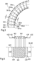
- Figure 3 shows a reinforcement hose 300 which is constructed from plastic elements screwed together.
- the plastic elements form half-shells 301 which are screwed together.
- Figure 3 is a top view of the half-shells 301.
- the half-shells 301 are substantially S-shaped and have an outward projection 302 at one end and an inward projection 303 at the opposite end.
- the half-shells are placed one inside the other in such a way that the projections 302, 303 interlock.
- Each half-shell 301 is screwed to a second half-shell 301 at the fastening points 304a-304c, so that an annular body with a circular cross section is created. In this way, the reinforcement tube 300 is produced from a plurality of half-shells 301 screwed together.
- the reinforcement tube 300 is designed to be flexible transversely to its longitudinal direction. For this purpose, a certain clearance S is present between the projections 302, 303 and a central web 306, which is shown in Figure 3 is marked with arrows.
- the play S is necessary in order to give the reinforcement hose 300 a certain flexibility. However, the play S also leads to the reinforcement hose 300 also being elongated in the axial direction. However, this elongation is limited by the game S and can be adjusted by appropriate dimensioning of the game S.
- the ends of the half-shells 301 are spherical, similar to a coolant or joint hose, the basically undesirable axial movement is greatly reduced.
- the hose 300 also serves to protect the line 100 from overbending
- the outer corrugated hose 102 is shown in cross-section above the dash-dotted line IV-IV.
- a top view of braid 109 and corrugated tube 102 is shown below dash-dotted line IV-IV.
- the braid 109 is welded together with a ring 401 to a cylindrical end connector 402 of the corrugated hose 102.
Landscapes
- Engineering & Computer Science (AREA)
- General Engineering & Computer Science (AREA)
- Mechanical Engineering (AREA)
- Thermal Insulation (AREA)
- Rigid Pipes And Flexible Pipes (AREA)
Abstract
Description
- Die Erfindung betrifft vakuumisolierte Leitung mit einem inneren und einem äußeren Wellschlauch. Außerdem betrifft die Erfindung eine Verladestation mit einer vakuumisolierten Leitung.
- Vakuumisolierte Leitungen für den Transport tiefkalter (kryogener) Medien umfassen häufig einen inneren und einen äußeren Wellschlauch aus Metall. Der Zwischenraum zwischen dem inneren und dem äußeren Wellschlauch ist evakuiert, um eine sehr gute Wärmeisolierung zu erzielen, damit während des Transportes eines kryogenen Mediums durch die Leitung das kryogene Medium möglichst wenig Wärme aufnimmt. Zusätzlich ist der innere Wellschlauch in der Regel mit einer Superisolation ummantelt und wird mittels Abstandshaltern mittig in dem äußeren Wellschlauch gehaltert.
- Da die Wellschläuche in axialer Richtung flexibel sind, führt der Druck des durch das Innenrohr transportierten kryogenen Mediums zu einer Längung der Leitung. Grundsätzlich ist eine solche Längung unerwünscht, weil sie zu einer unkontrollierten Bewegung der Leitung führen kann, die zu Beschädigungen an der Leitung oder an Objekten führen kann, die mit der Leitung in Berührung stehen. Um eine übermäßige Längung zu verhindern, ist es bekannt, den inneren und/oder den äußeren Wellschlauch mit einem Geflecht zu ummanteln. Das Geflecht ist zugfest und setzt der Längung der Leitung eine Grenze. Allerdings kann das Geflecht nur Zugkräfte aufnehmen, aber keine Druckkräfte, was dazu führt, dass sich bei der Herstellung der vakuumisolierten Leitung die Leitung zunächst verkürzt, wenn der Zwischenraum zwischen dem inneren Wellschlauch und dem äußeren Wellschlauch evakuiert wird. Wenn im Betrieb ein Medium mit Druck durch die Leitung transportiert wird, streckt sich die vakuumisolierte Leitung wieder, weil das Geflecht die dabei entstehenden Zugkräfte zunächst nicht aufnimmt bis es seine maximale Länge erreicht hat.
- Bei den mit einem Geflecht ausgerüsteten vakuumisolierten Leitungen wird die Längenausdehnung zwar begrenzt, wenn ein Medium mit Druck durch die Leitung transportiert wird, aber die Längenausdehnung wird nicht gänzlich vermieden. Dabei spielt es keine Rolle, ob das Geflecht auf dem inneren Wellschlauch oder dem äußeren Wellschlauch angeordnet ist. Auch wenn sowohl der innere als auch der äußere Wellschlauch mit einem Geflecht ummantelt sind, ändert das an dem beschriebenen Verhalten grundsätzlich nichts.
- Hiervon ausgehend hat die vorliegende Erfindung die Aufgabe, eine vakuumisolierte Leitung zu schaffen, um eines oder mehrere der eingangs genannten Probleme zu überwinden oder zumindest zu verbessern.
- Zur Lösung dieser Aufgabe schlägt die Erfindung nach einem ersten Aspekt eine vakuumisolierte Leitung mit einem inneren und einem äußeren Wellschlauch vor, die durch einen evakuierten Zwischenraum voneinander getrennt sind. Einer der Wellschläuche ist mit einem Verstärkungsschlauch ummantelt, der in axialer Richtung zug- und/oder druckfest ist.
- Bei einer vorteilhaften Ausführungsform ist der Verstärkungsschlauch als Wickelschlauch ausgebildet. Bei einer anderen vorteilhaften Ausführungsform ist der Verstärkungsschlauch aus miteinander verbundenen Kunststoffelementen aufgebaut, die zueinander beweglich sind. Ebenso wie der Wickelschlauch ist der Verstärkungsschlauch aus miteinander verbundenen Kunststoffelementen in axialer Richtung zug- und/oder druckfest. Ein Verstärkungsschlauch aus Kunststoff ist zum Beispiel überall dort von Vorteil, wo die Entstehung von Funken vermieden werden muss, weil eine erhöhte Explosionsgefahr besteht.
- Mit dem Verstärkungsschlauch bzw. Wickelschlauch werden die mechanischen Eigenschaften der Leitung verbessert, beispielsweise schützt der Wickelschlauch die Leitung vor äußeren mechanischen Belastungen oder sogar Beschädigungen. Der Wickelschlauch dient gleichzeitig als Überbiegeschutz für die Wellschläuche. Mit dem Verstärkungsschlauch aus miteinander verbundenen Kunststoffelementen werden dieselben Vorteile verwirklicht wie mit einem Wickelschlauch, wobei die Vorteile bei den beiden Ausführungsformen graduell unterschiedlich stark ausgeprägt sein können.
- Allen Ausführungsformen ist gemeinsam, dass die vakuumisolierte Leitung ihre Länge nicht wesentlich verändert, wenn sie bei dem Transport von einem Medium im Inneren mit Druck beaufschlagt ist. Insbesondere mit Wickelschläuchen lässt sich die Längung der Leitung gänzlich verhindern, wenn die Leitung mit Druck beaufschlagt wird.
- Mit Vorteil sind die Wellschläuche in Umfangsrichtung gewellt und biegeflexibel ausgebildet.
- Zweckmäßigerweise ist auch der Verstärkungsschlauch biegeflexibel ausgebildet ist. Die Flexibilität des Verstärkungsschlauchs sorgt dafür, dass die vakuumisolierte Leitung insgesamt flexibel bleibt und am jeweiligen Einsatzort einfach zu verlegen ist.
- Bei einem Ausführungsbeispiel ist der Wickelschlauch aus miteinander verbundenen Metallstreifen aufgebaut. Ein solcher Wickelschlauch ist mechanisch stabil und kostengünstig herzustellen.
- Zweckmäßigerweise können der innere und der äußere Wellschlauch an ihren Enden vakuumdicht miteinander verschweißt sein.
- Bei einem weiteren Ausführungsbeispiel der Leitung ist entweder der innere oder der äußere Wellschlauch mit dem Verstärkungsschlauch ummantelt, während der andere Wellschlauch mit einem Geflecht ummantelt ist. Bei diesem Ausführungsbeispiel wird üblicherweise der äußere Wellschlauch mit dem Verstärkungsschlauch umwickelt sein, weil dadurch gleichzeitig ein guter mechanischer Schutz gegen Querdruckbelastbarkeit erzielt wird. Grundsätzlich kann der Verstärkungsschlauch aber auch auf dem inneren Wellschlauch angeordnet sein. Beide Varianten haben gleichermaßen die Eigenschaft, dass sie ihre Länge im Wesentlichen nicht verändern, wenn sie ein unter Druck stehendes Medium transportieren.
- Nach einem zweiten Aspekt schlägt die Erfindung eine Verladeeinrichtung für kryogene Fluide mit einer Leitung gemäß dem ersten Aspekt der Erfindung vor. Die Verladeeinrichtung vermeidet Probleme, die aus einer Längung der Leitung resultieren, wenn die Leitung zum Transport des kryogenen Fluids mit Druck beaufschlagt wird.
- Nachfolgend wird die Erfindung anhand einer Ausführungsform unter Bezugnahme auf die begleitenden Figuren exemplarisch näher erläutert. Alle Figuren sind rein schematisch und nicht maßstäblich. Es zeigen:
- Fig. 1a-1c
- unterschiedliche Zustände einer herkömmlichen vakuumisolierten Leitung; und
- Fig. 2
- eine erfindungsgemäße vakuumisolierte Leitung;
- Fig. 3
- ein Schlauch aus miteinander verbundenen Kunststoffelementen; und
- Fig. 4
- die Befestigung eines Geflechts auf einem Wellschlauch.
- Gleiche oder ähnliche Elemente sind in den Figuren mit gleichen oder ähnlichen Bezugszeichen versehen.
-
Figur 1a zeigt im Querschnitt eine Leitung 100, die einen inneren Wellschlauch 101 und einen äußeren Wellschlauch 102 aufweist, die durch einen Zwischenraum 103 voneinander getrennt sind. Der innere Wellschlauch 101 ist mit einer Superisolation ummantelt und wird mit Abstandshaltern mittig in dem äußeren Wellschlauch 102 gehaltert. Der Übersichtlichkeit halber sind die Superisolation und die Abstandshalter inFigur 1a nicht dargestellt. Die Wellschläuche 101,102 sind in Umfangsrichtung gewellt und daher quer zu ihrer Längsausdehnung biegeflexibel und in axialer Richtung dehnbar. - An ihren jeweiligen Enden sind die Wellschläuche 101,102 vakuumdicht miteinander verschweißt unter Ausnahme eines Kleinflansches 106, der für die Evakuierung des Zwischenraumes 103 benötigt wird. Die Wellschläuche 101,102 sind mit einem zugfesten Geflecht 108,109 aus Stahldraht ummantelt und an den jeweiligen Enden des inneren bzw. äußeren Wellschlauch 101,102 befestigt. Das Geflecht wird üblicherweise zusammen mit einem Ring 401 (
Figur 4 ) auf den zylindrischen Endstutzen 402 (Figur 4 ) des Wellschlauchs aufgeschweißt. Bei anderen Ausführungsbespielen kann es auch beispielsweise mit einem Klemmring (nicht dargestellt) befestigt sein. Bei anderen Ausführungsbeispielen ist nur der innere Wellschlauch 101 oder nur der äußere Wellschlauch 102 mit einem Geflecht 108 bzw. 109 ummantelt. In diesem Fall ist das Geflecht so ausgelegt, dass nur ein einziges Geflecht die auftretenden Kräfte aufnehmen kann. - An den Enden der Leitung 100 wird je nach Anwendungsfall ein Verbindungsflansch zum Verbinden der Leitung 100 mit einer Anschlussstelle oder einer weiteren Leitung angeschweißt. Gegebenenfalls wird an einem oder beiden Enden der Leitung 100 eine Kupplung angebracht. Das kann zum Beispiel eine QCDC-Kupplung ("Quick Connect/Disconnect Coupler") oder eine Johnston-Kupplung sein. Die Wellschläuche 101,102 sind aus rostfreiem Stahl hergestellt. Die Verbindungsflansche bzw. Kupplungen sind in den Figuren nicht dargestellt.
-
Figur 1a zeigt eine zusammen gebaute Leitung, bei der der Zwischenraum 103 noch nicht evakuiert ist. In diesem Zustand sind die Wellschläuche 101,102 und die Gewebe 108,109 entspannt. Die Leitung 100 hat in diesem Zustand eine Länge L1. - Zur Fertigstellung der Leitung wird der Zwischenraum 103 evakuiert, um eine Vakuumisolierung herzustellen. Dazu wird eine Vorrichtung auf dasjenige Ende der Leitung 100 gesetzt, wo sich der Kleinflansch 106 befindet. Die Vorrichtung ermöglicht es einerseits eine Vakuumpumpe anzuschließen, die den Zwischenraum 103 evakuiert. Andererseits gestattet es die Vorrichtung, einen Verschlussstopfen 107 (
Figur 1b ) in den Kleinflansch 106 einzuschrauben, der den Zwischenraum 103 vakuumdicht verschließt und zwar während die Pumpe noch angeschlossen und in Betrieb ist. Der Kleinflansch 106 wird dann verschlossen, wenn der Druck in dem Zwischenraum 103 auf einen vorbestimmten Wert gesunken ist. - Schon während der Zwischenraum 103 abgepumpt wird, verkürzt sich die Leitung 100 unter dem Einfluss des atmosphärischen Drucks in axialer Richtung auf die Länge L2 wie es in
Figur 1b gezeigt ist. In radialer Richtung sind die Wellschläuche 101,102 im wesentlichen druckstabil und verformen sich deshalb in radialer Richtung nicht. Die Geflechte 108,109 schieben sich dabei zusammen, wobei keine nennenswerte Gegenkraft erzeugt wird. -
Figur 1c zeigt die im Betrieb befindliche Leitung 100, die ein unter Druck stehendes Medium im Innenraum 111 des inneren Wellschlauchs 101 transportiert. Dabei dehnt sich die Leitung 100 in axialer Richtung bis auf eine Länge L3 aus, die begrenzt wird durch die maximale Längendehnung, welche die Gewebe 108,109 zulassen. - Wird der Druck im Inneren der Leitung 100 wieder reduziert, weil zum Beispiel ein Tankvorgang beendet ist, dann verkürzt sich die Leitung wieder auf die Länge L2 (
Figur 1B ). Die Längendifferenz zwischen den beiden Zuständen beträgt ΔL = L3 - L2. - Die Flexibilität der Leitung 100 hängt unter anderem von dem Abstand der Wellungen und der Welttiefe der Wellschläuche 101,102 ab. Ein konkretes Ausführungsbeispiel der Leitung 100 weist in der Praxis folgende Werte auf: L1 = 10 m; L2 = 9,6 m und L3 = 10,1 m. Die Evakuierung des Zwischenraums zwischen den Wellschläuchen 101,102 führt somit zu einer Verkürzung der Leitung um 4 %. Außerdem ist anzumerken, dass die Längenzunahme auch von dem Innendruck in der Leitung 100 abhängt.
- Der Durchmesser der Leitung 100 kann beispielsweise 0,1 m bis 0,2 m betragen.
- Für den Transport eines Mediums zwischen zwei festen Punkten werden in der Praxis häufig mehrere Leitungen miteinander verbunden. Werden beispielsweise eine Anzahl von N Leitungen miteinander verbunden, so hat die ganze Leitung eine Gesamtlänge von N * L2 und im Betrieb nimmt die Gesamtlänge auf N * L3 zu. Die Längenänderung zwischen beiden Zuständen ist dementsprechend N *ΔL und kann die eingangs beschriebenen Probleme verursachen.
- Bei einem in
Figur 2 dargestellten Ausführungsbeispiel einer erfindungsgemäßen Leitung 200 ist deshalb mindestens das Gewebe auf dem äußeren Wellschlauch 102 durch einen Wickelschlauch 201 ersetzt, der in axialer Richtung sowohl zug- als auch druckfest ist. - Der vergrößerte Ausschnitt in
Figur 2 zeigt eine Einzelheit des Wickelschlauchs 201, der aus gefalzten und ineinandergesteckten Metallstreifen 202 hergestellt ist. Die Längen der Falze sind so bemessen, dass sich die Metallstreifen 202 in axialer Richtung nicht gegeneinander verschieben können. Dadurch wird der Wickelschlauch in axialer Richtung zug- und druckfest. In radialer Richtung ist der Wickelschlauch 201 ohnehin druckfest. Der innere Wellschlauch 101 ist mit einem Gewebe 108 ummantelt. - Der Wickelschlauch 201 ist aus Metall hergestellt, zum Beispiel aus Edelstahl, Aluminium oder einer Aluminiumlegierung. Grundsätzlich kommen auch Materialkombinationen aus Metall und Kunststoff infrage, solange die axiale Zug- und Druckfestigkeit des Wickelschlauchs gewährleistet ist. Die mit dem Wickelschlauch 201 ummantelte Leitung 200 behält deshalb in allen im Zusammenhang mit den
Figuren 1a bis 1c beschriebenen Situationen stets dieselbe Länge L1. Mit anderen Worten: Bei der Leitung 200 tritt in unterschiedlichen Betriebssituationen keine Längenänderung auf. Dadurch werden auch sämtliche potentielle Gefahren, die mit einer Längenänderung verbunden sind, von vornherein vermieden. - Der Wickelschlauch 201 auf dem äußeren Wellschlauch 102 bildet gleichzeitig einen sehr guten mechanischen Schutz gegen äußere Einflüsse, weil der Wickelschlauch 201 unter anderem auch eine sehr gute Querdruckbelastbarkeit aufweist.
- Aufgrund seiner Form lässt sich der Wickelschlauch 201 auch nicht überbiegen. Er dient damit auch gleichzeitig als Überbiegeschutz für die Wellschläuche 101,102.
- Bei einem anderen Ausführungsbeispielen können anstelle des Wickelschlauchs aus Metall auch entsprechend gestaltete Elemente aus Kunststoff verwendet werden, die aufgrund ihrer Gestalt die Funktion des Wickelschlauchs übernehmen.
- Bei anderen Ausführungsbeispielen ist auch das Gewebe 108, welches den inneren Wellschlauch ummantelt, durch einen Wickelschlauch ersetzt.
- Bei allen Ausführungsbeispielen sind jedoch sowohl der innere als auch der äußere Wellschlauch 101,102 nicht durch einen Wickelschlauch ersetzbar, weil ein Wickelschlauch nicht die erforderliche Dichtigkeit zur Begrenzung des Vakuums in dem Zwischenraum 103 aufweist.
-
Figur 3 zeigt einen Verstärkungsschlauch 300, der aus miteinander verschraubten Kunststoffelementen aufgebaut ist. Die Kunststoffelemente bilden Halbschalen 301, die miteinander verschraubt sind.Figur 3 ist eine Draufsicht auf die Halbschalen 301. Die Halbschalen 301 im wesentlichen S-förmig ausgebildet und weisen an einem Ende einen nach außen gerichteten Vorsprung 302 und an dem gegenüberliegenden Ende einen nach innen gerichteten Vorsprung 303 auf. Die Halbschalen werden so ineinander gelegt, dass die Vorsprünge 302, 303 ineinandergreifen. Jede Halbschale 301 wird mit einer zweiten Halbschale 301 an den Befestigungspunkten 304a- 304c verschraubt, sodass ein Ringkörper mit einem kreisförmigen Querschnitt entsteht. Aus einer Mehrzahl von miteinander verschraubten Halbschalen 301 entsteht auf diese Weise der Verstärkungsschlauch 300. Der Verstärkungsschlauch 300 ist quer zu seiner Längsrichtung flexibel ausgestaltet. Zwischen den Vorsprüngen 302,303 und einem Mittelsteg 306 ist zu diesem Zweck ein gewisses Spiel S vorhanden, das inFigur 3 mit Pfeilen markiert ist. Das Spiel S ist notwendig, um dem Verstärkungsschlauch 300 eine gewisse Flexibilität zu verleihen. Allerdings führt das Spiel S auch dazu, dass der Verstärkungsschlauch 300 sich auch in axialer Richtung längt. Diese Längung ist jedoch durch das Spiel S begrenzt und durch eine entsprechende Bemessung des Spieles S einstellbar. - Werden die Enden der Halbschalen 301 ähnlich wie bei einem Kühlmittel- oder Gelenkschlauch kugelförmig ausgebildet, so wird die grundsätzlich unerwünschte axiale Bewegung stark reduziert.
- Der Schlauch 300 dient auch zum Schutz vor einem Überbiegen der Leitung 100
- In
Figur 4 ist beispielhaft die Befestigung des Geflechts 109 auf dem äußeren Wellschlauchs 102 dargestellt. Die Befestigung des Geflechts 108 auf dem inneren Wellschlauch erfolgt in gleicher Weise. - In dem oberen Teil der
Figur 4 oberhalb der strichpunktierten Linie IV-IV ist der äußere Wellschlauch 102 in einem Querschnitt dargestellt. In dem unteren Teil derFigur 4 unterhalb der strichpunktierten Linie IV-IV ist eine Draufsicht auf das Geflecht 109 und den Wellschlauch 102 gezeigt. Das Geflecht 109 wird zusammen mit jeweils einem Ring 401 auf einen zylindrischen Endstutzen 402 des Wellschlauchs 102 aufgeschweißt. -
- 100
- Leitung
- 101
- innerer Wellschlauch
- 102
- äußere Wellschlauch
- 103
- Zwischenraum
- 106
- Kleinflansch
- 107
- Verschlussstopfen
- 108
- Geflecht
- 109
- Geflecht
- 200
- Leitung
- 201
- Wickelschlauch
- 202
- Metallstreifen
- 300
- Schlauch
- 301
- Halbschalen
- 302
- Vorsprung
- 303
- Vorsprung
- 304a- 304c
- Befestigungspunkte
- 306
- Mittelsteg
- 401
- Ring
- 402
- Endstutzen
Claims (9)
- Vakuumisolierte Leitung (100) mit einem inneren und einem äußeren Wellschlauch (101,102), die durch einen evakuierten Zwischenraum (103) voneinander getrennt sind, dadurch gekennzeichnet, dass einer der Wellschläuche (101,102) mit einem Verstärkungsschlauch (,300) ummantelt ist, der in axialer Richtung zug- und/oder druckfest ist.
- Leitung nach Anspruch 1, dadurch gekennzeichnet, dass der Verstärkungsschlauch als Wickelschlauch (201,300) ausgebildet ist.
- Leitung nach Anspruch 1, dadurch gekennzeichnet, dass der Verstärkungsschlauch (300) aus miteinander verbundenen Kunststoffelementen (301) aufgebaut ist, die zueinander beweglich sind.
- Leitung nach Anspruch 1 oder 2, dadurch gekennzeichnet, dass die Wellschläuche (101,102) in Umfangsrichtung gewellt und biegeflexibel ausgebildet sind.
- Leitung nach einem der vorstehenden Ansprüche, dadurch gekennzeichnet, dass der Verstärkungsschlauch (201,300) biegeflexibel ausgebildet ist.
- Leitung nach Anspruch 2, dadurch gekennzeichnet, dass der Wickelschlauch (201) aus miteinander verbundenen Metallstreifen (202) aufgebaut ist.
- Leitung nach einem der vorstehenden Ansprüche, dadurch gekennzeichnet, dass der innere und der äußere Wellschlauch (101,102) an ihren Enden vakuumdicht miteinander verschweißt sind.
- Leitung nach einem der vorstehenden Ansprüche, dadurch gekennzeichnet, dass entweder der innere oder der äußere Wellschlauch (101,102) mit dem Verstärkungsschlauch (201,300) ummantelt ist, während der andere Wellschlauch mit einem Geflecht (108,109) ummantelt ist.
- Verladeeinrichtung für kryogene Fluide mit einer Leitung (200) nach einem der vorstehenden Ansprüche.
Priority Applications (3)
| Application Number | Priority Date | Filing Date | Title |
|---|---|---|---|
| EP18306734.7A EP3670997B1 (de) | 2018-12-19 | 2018-12-19 | Flexible vakuumisolierte leitung |
| US16/713,369 US11796118B2 (en) | 2018-12-19 | 2019-12-13 | Flexible vacuum-insulated line |
| JP2019225688A JP7495789B2 (ja) | 2018-12-19 | 2019-12-13 | 可撓性真空断熱ライン |
Applications Claiming Priority (1)
| Application Number | Priority Date | Filing Date | Title |
|---|---|---|---|
| EP18306734.7A EP3670997B1 (de) | 2018-12-19 | 2018-12-19 | Flexible vakuumisolierte leitung |
Publications (2)
| Publication Number | Publication Date |
|---|---|
| EP3670997A1 true EP3670997A1 (de) | 2020-06-24 |
| EP3670997B1 EP3670997B1 (de) | 2022-07-06 |
Family
ID=65278151
Family Applications (1)
| Application Number | Title | Priority Date | Filing Date |
|---|---|---|---|
| EP18306734.7A Active EP3670997B1 (de) | 2018-12-19 | 2018-12-19 | Flexible vakuumisolierte leitung |
Country Status (3)
| Country | Link |
|---|---|
| US (1) | US11796118B2 (de) |
| EP (1) | EP3670997B1 (de) |
| JP (1) | JP7495789B2 (de) |
Cited By (1)
| Publication number | Priority date | Publication date | Assignee | Title |
|---|---|---|---|---|
| EP4524093A1 (de) * | 2023-09-13 | 2025-03-19 | SVT GmbH | Verladearm-vorrichtung sowie verfahren zum umrüsten einer verladearm-vorrichtung |
Families Citing this family (6)
| Publication number | Priority date | Publication date | Assignee | Title |
|---|---|---|---|---|
| FR3109420B1 (fr) * | 2020-04-15 | 2022-08-26 | Serac Group | Canalisation et installation de remplissage de récipients comprenant une telle canalisation |
| EP4235002A1 (de) * | 2022-02-25 | 2023-08-30 | MAGNA Energy Storage Systems GesmbH | Thermisch isolierte transferleitung |
| EP4407223B1 (de) * | 2023-01-24 | 2026-04-22 | Airbus Operations GmbH | Gasverteilungssystem für flugzeuge |
| GB2639175A (en) | 2024-03-01 | 2025-09-17 | Enoflex Ltd | Cryogenic fluid transfer |
| GB202408554D0 (en) * | 2024-06-14 | 2024-07-31 | Rigmech Services Ltd | Connector |
| GB2642473A (en) | 2024-07-09 | 2026-01-14 | Enoflex Ltd | Cryogenic fluid transfer |
Citations (3)
| Publication number | Priority date | Publication date | Assignee | Title |
|---|---|---|---|---|
| US6065501A (en) * | 1989-06-30 | 2000-05-23 | Institute Francais Du Petrole | Flexible tube having at least one elongated reinforcing element with a T-shaped profile |
| WO2013120459A1 (zh) * | 2012-02-17 | 2013-08-22 | 北京兆阳能源技术有限公司 | 一种管路柔性连接装置及其使用方法 |
| FR2997747A1 (fr) * | 2012-11-08 | 2014-05-09 | Technip France | Conduite flexible de transport d'un fluide cryogenique, installation et procede associes |
Family Cites Families (32)
| Publication number | Priority date | Publication date | Assignee | Title |
|---|---|---|---|---|
| US1699911A (en) * | 1925-07-11 | 1929-01-22 | Fed Metal Hose Corp | Coupling for flexible metal hose |
| US2056840A (en) * | 1935-12-20 | 1936-10-06 | Pennsylvania Flexible Metallic | Flexible conduit |
| US2256386A (en) * | 1938-12-27 | 1941-09-16 | Chicago Metal Hose Corp | Hose construction |
| US3240234A (en) * | 1960-02-24 | 1966-03-15 | Union Carbide Corp | Hose for low-temperature liquids |
| US3204666A (en) * | 1962-12-17 | 1965-09-07 | Calumet & Hecla | Helically wound flexible hose |
| US3490496A (en) * | 1968-01-15 | 1970-01-20 | Vacuum Barrier Corp | Coaxial tubing having improved spacer means |
| DE2064053A1 (de) * | 1970-12-28 | 1972-07-06 | Kabel Metallwerke Ghh | Rohrförmiges metallisches Gebilde mit Schraubenlinien- oder ringförmiger Wellung |
| US3934618A (en) * | 1974-08-26 | 1976-01-27 | Controls Southeast, Inc. | Jacketed pipe assembly formed of corrugated metal tubes |
| US4036618A (en) * | 1975-04-18 | 1977-07-19 | Cryogenic Technology, Inc. | Flexible cryogenic envelope |
| FR2458022A1 (fr) * | 1979-05-30 | 1980-12-26 | Coflexip | Conduite tubulaire flexible |
| JPS56138585A (en) * | 1980-03-28 | 1981-10-29 | Tokyo Shibaura Electric Co | Low temperature pipeline |
| JPH0412298Y2 (de) * | 1986-12-26 | 1992-03-25 | ||
| DE3803112A1 (de) * | 1988-02-03 | 1989-08-17 | Kabelmetal Electro Gmbh | Leitungsrohr zum transport von tiefgekuehlten medien |
| JP2592153B2 (ja) * | 1989-12-22 | 1997-03-19 | 象印マホービン株式会社 | 真空二重管 |
| DE29701625U1 (de) * | 1997-01-31 | 1997-03-20 | Witzenmann GmbH Metallschlauch-Fabrik Pforzheim, 75175 Pforzheim | Flexibles Leitungselement für Abgasleitungen |
| US5884670A (en) * | 1997-05-06 | 1999-03-23 | Tigers Poymer Corporation | Synthetic resin tube and producing method thereof |
| DE19846587C1 (de) * | 1998-10-09 | 2000-03-16 | Karlsruhe Forschzent | Stützsystem für Superisolation |
| JP2000146083A (ja) | 1998-11-10 | 2000-05-26 | Kana Flex Corporation Kk | 可撓性を有する流体用管 |
| US6354332B1 (en) * | 1999-04-30 | 2002-03-12 | Witzenmann Gmbh, Metallschlauch-Fabrik Pforzheim | Coolant line for air conditioning systems |
| EP1975492A3 (de) * | 1999-11-05 | 2009-07-01 | Wellstream International Limited | Biegsames Rohr und Herstellungsverfahren dafür |
| US6513552B1 (en) * | 2001-09-28 | 2003-02-04 | General Machinery Of Pittsburgh, Inc. | Multi-flex stainless steel roof drain hose |
| US20050011573A1 (en) * | 2003-07-14 | 2005-01-20 | American Boa, Inc. | Flexible liner air gap pipe |
| GB0414837D0 (en) * | 2004-07-02 | 2004-08-04 | Booth John P | Improvements in or relating to tubular bodies and methods of forming same |
| DK1795796T3 (da) * | 2005-12-09 | 2009-08-03 | Nexans | Ledningsrör til transport af dybfrosne medier |
| BRPI0710425A8 (pt) * | 2006-05-08 | 2019-01-15 | Bhp Billiton Petroleum Pty Ltd | mangueira, uso de uma mangueira , método para fabricar mangueira e aparelho para fabricar mangueira |
| US7650912B2 (en) * | 2007-11-06 | 2010-01-26 | Sjm Co., Ltd. | Flexible conduit element |
| GB0805342D0 (en) * | 2008-03-25 | 2008-04-30 | Flexlife Ltd | Metod and apparatus for repairing tubular members |
| EP2146125B1 (de) * | 2008-07-17 | 2011-11-02 | Nexans | Flexibles Leitungsrohr |
| FR2937706B1 (fr) * | 2008-10-29 | 2013-02-22 | Saipem Sa | Ensemble de conduites coaxiales comprenant un manchon d'isolation thermique |
| NO336854B1 (no) * | 2011-03-21 | 2015-11-16 | Nexans | Modulær bøyestiver |
| US9163463B2 (en) * | 2011-06-01 | 2015-10-20 | Deep Down, Inc. | Bend limiting stiffener and related methods |
| NL2008092C2 (nl) * | 2012-01-10 | 2013-07-15 | Lankhorst Mouldings B V | Buigingsbeperkingselement voor het beperken van het buigingsbereik van een leiding. |
-
2018
- 2018-12-19 EP EP18306734.7A patent/EP3670997B1/de active Active
-
2019
- 2019-12-13 JP JP2019225688A patent/JP7495789B2/ja active Active
- 2019-12-13 US US16/713,369 patent/US11796118B2/en active Active
Patent Citations (3)
| Publication number | Priority date | Publication date | Assignee | Title |
|---|---|---|---|---|
| US6065501A (en) * | 1989-06-30 | 2000-05-23 | Institute Francais Du Petrole | Flexible tube having at least one elongated reinforcing element with a T-shaped profile |
| WO2013120459A1 (zh) * | 2012-02-17 | 2013-08-22 | 北京兆阳能源技术有限公司 | 一种管路柔性连接装置及其使用方法 |
| FR2997747A1 (fr) * | 2012-11-08 | 2014-05-09 | Technip France | Conduite flexible de transport d'un fluide cryogenique, installation et procede associes |
Cited By (1)
| Publication number | Priority date | Publication date | Assignee | Title |
|---|---|---|---|---|
| EP4524093A1 (de) * | 2023-09-13 | 2025-03-19 | SVT GmbH | Verladearm-vorrichtung sowie verfahren zum umrüsten einer verladearm-vorrichtung |
Also Published As
| Publication number | Publication date |
|---|---|
| EP3670997B1 (de) | 2022-07-06 |
| US20200224816A1 (en) | 2020-07-16 |
| US11796118B2 (en) | 2023-10-24 |
| JP7495789B2 (ja) | 2024-06-05 |
| JP2020101280A (ja) | 2020-07-02 |
Similar Documents
| Publication | Publication Date | Title |
|---|---|---|
| EP3670997B1 (de) | Flexible vakuumisolierte leitung | |
| DE4034055A1 (de) | Flexibles leitungselement fuer abgasleitungen von verbrennungsmotoren bei kraftfahrzeugen | |
| EP2330326A1 (de) | Rohrförmiges Bauteil | |
| EP1048881B1 (de) | Kältemittelleitung für Klimaanlagen | |
| DD298542A5 (de) | Rohrkupplung | |
| EP0458011B1 (de) | Leitungselement, insbesondere für die Abgasleitung von Verbrennungskraftmaschinen | |
| EP1041331A2 (de) | Anschlusselement für einen Verbundschlauch und Verfahren zum Anschliessen eines Verbundschlauchs | |
| DE4438213A1 (de) | Leitungselement, insbesondere für die Abgasleitung von Verbrennungskraftmaschinen | |
| EP2728233A2 (de) | Flexibles Leitungselement | |
| DE19744663A1 (de) | Leitungselement in Form eines Wellschlauches oder Balges | |
| EP2995837B1 (de) | Kältemittelleitung | |
| DE2204240A1 (de) | Luftschlauch | |
| EP0436772A2 (de) | Leitungselement in Form eines Wellschlauches oder Balges | |
| EP1927803B1 (de) | Flexibles Leitungselement für innendruckbeaufschlagte Leitungen | |
| DE102010034679A1 (de) | Dickstoffpumpe | |
| CH262058A (de) | Vorrichtung zur Längenbegrenzung eines Federrohres, insbesondere für Dehnungsausgleicher. | |
| DE2557713C2 (de) | Rohrgelenk | |
| EP0568835B1 (de) | Kompensationselement für Kunststoffmantelrohrleitungen | |
| DE102018117566A1 (de) | Flexibles Leitungselement mit Verstärkungselementen und Verfahren zum Herstellen desselben | |
| DE4134899C1 (en) | Flexible safety pipe for fluid media - comprises plastic core with plastic mantle and intermediate spiral chamber, with inner spiral corrugated plastic tube | |
| EP0523340B1 (de) | Druckentlasteter Eckrohrbogenkompensator | |
| EP1599690B1 (de) | Rohrkupplung mit gummielastischer dichtmanschette | |
| DE3544884C2 (de) | Biegbarer Hochdruck-Metall-Ringwellschlauch | |
| DE2808475C3 (de) | Torsionskompensator für Rohrleitungen | |
| DE102015109850A1 (de) | Schlauchsystem |
Legal Events
| Date | Code | Title | Description |
|---|---|---|---|
| PUAI | Public reference made under article 153(3) epc to a published international application that has entered the european phase |
Free format text: ORIGINAL CODE: 0009012 |
|
| STAA | Information on the status of an ep patent application or granted ep patent |
Free format text: STATUS: THE APPLICATION HAS BEEN PUBLISHED |
|
| AK | Designated contracting states |
Kind code of ref document: A1 Designated state(s): AL AT BE BG CH CY CZ DE DK EE ES FI FR GB GR HR HU IE IS IT LI LT LU LV MC MK MT NL NO PL PT RO RS SE SI SK SM TR |
|
| AX | Request for extension of the european patent |
Extension state: BA ME |
|
| STAA | Information on the status of an ep patent application or granted ep patent |
Free format text: STATUS: REQUEST FOR EXAMINATION WAS MADE |
|
| 17P | Request for examination filed |
Effective date: 20210111 |
|
| RBV | Designated contracting states (corrected) |
Designated state(s): AL AT BE BG CH CY CZ DE DK EE ES FI FR GB GR HR HU IE IS IT LI LT LU LV MC MK MT NL NO PL PT RO RS SE SI SK SM TR |
|
| GRAP | Despatch of communication of intention to grant a patent |
Free format text: ORIGINAL CODE: EPIDOSNIGR1 |
|
| STAA | Information on the status of an ep patent application or granted ep patent |
Free format text: STATUS: GRANT OF PATENT IS INTENDED |
|
| RIC1 | Information provided on ipc code assigned before grant |
Ipc: F16L 11/20 20060101ALI20220216BHEP Ipc: F16L 11/18 20060101ALI20220216BHEP Ipc: F16L 11/16 20060101ALI20220216BHEP Ipc: F16L 11/15 20060101ALI20220216BHEP Ipc: F16L 59/153 20060101ALI20220216BHEP Ipc: F16L 59/14 20060101ALI20220216BHEP Ipc: F16L 59/065 20060101AFI20220216BHEP |
|
| INTG | Intention to grant announced |
Effective date: 20220321 |
|
| GRAS | Grant fee paid |
Free format text: ORIGINAL CODE: EPIDOSNIGR3 |
|
| GRAA | (expected) grant |
Free format text: ORIGINAL CODE: 0009210 |
|
| STAA | Information on the status of an ep patent application or granted ep patent |
Free format text: STATUS: THE PATENT HAS BEEN GRANTED |
|
| AK | Designated contracting states |
Kind code of ref document: B1 Designated state(s): AL AT BE BG CH CY CZ DE DK EE ES FI FR GB GR HR HU IE IS IT LI LT LU LV MC MK MT NL NO PL PT RO RS SE SI SK SM TR |
|
| REG | Reference to a national code |
Ref country code: AT Ref legal event code: REF Ref document number: 1503094 Country of ref document: AT Kind code of ref document: T Effective date: 20220715 Ref country code: CH Ref legal event code: EP |
|
| REG | Reference to a national code |
Ref country code: IE Ref legal event code: FG4D Free format text: LANGUAGE OF EP DOCUMENT: GERMAN |
|
| REG | Reference to a national code |
Ref country code: DE Ref legal event code: R096 Ref document number: 502018010082 Country of ref document: DE |
|
| REG | Reference to a national code |
Ref country code: NO Ref legal event code: T2 Effective date: 20220706 |
|
| REG | Reference to a national code |
Ref country code: LT Ref legal event code: MG9D |
|
| REG | Reference to a national code |
Ref country code: NL Ref legal event code: MP Effective date: 20220706 |
|
| PG25 | Lapsed in a contracting state [announced via postgrant information from national office to epo] |
Ref country code: SE Free format text: LAPSE BECAUSE OF FAILURE TO SUBMIT A TRANSLATION OF THE DESCRIPTION OR TO PAY THE FEE WITHIN THE PRESCRIBED TIME-LIMIT Effective date: 20220706 Ref country code: RS Free format text: LAPSE BECAUSE OF FAILURE TO SUBMIT A TRANSLATION OF THE DESCRIPTION OR TO PAY THE FEE WITHIN THE PRESCRIBED TIME-LIMIT Effective date: 20220706 Ref country code: PT Free format text: LAPSE BECAUSE OF FAILURE TO SUBMIT A TRANSLATION OF THE DESCRIPTION OR TO PAY THE FEE WITHIN THE PRESCRIBED TIME-LIMIT Effective date: 20221107 Ref country code: NL Free format text: LAPSE BECAUSE OF FAILURE TO SUBMIT A TRANSLATION OF THE DESCRIPTION OR TO PAY THE FEE WITHIN THE PRESCRIBED TIME-LIMIT Effective date: 20220706 Ref country code: LV Free format text: LAPSE BECAUSE OF FAILURE TO SUBMIT A TRANSLATION OF THE DESCRIPTION OR TO PAY THE FEE WITHIN THE PRESCRIBED TIME-LIMIT Effective date: 20220706 Ref country code: LT Free format text: LAPSE BECAUSE OF FAILURE TO SUBMIT A TRANSLATION OF THE DESCRIPTION OR TO PAY THE FEE WITHIN THE PRESCRIBED TIME-LIMIT Effective date: 20220706 Ref country code: FI Free format text: LAPSE BECAUSE OF FAILURE TO SUBMIT A TRANSLATION OF THE DESCRIPTION OR TO PAY THE FEE WITHIN THE PRESCRIBED TIME-LIMIT Effective date: 20220706 Ref country code: ES Free format text: LAPSE BECAUSE OF FAILURE TO SUBMIT A TRANSLATION OF THE DESCRIPTION OR TO PAY THE FEE WITHIN THE PRESCRIBED TIME-LIMIT Effective date: 20220706 |
|
| PG25 | Lapsed in a contracting state [announced via postgrant information from national office to epo] |
Ref country code: PL Free format text: LAPSE BECAUSE OF FAILURE TO SUBMIT A TRANSLATION OF THE DESCRIPTION OR TO PAY THE FEE WITHIN THE PRESCRIBED TIME-LIMIT Effective date: 20220706 Ref country code: IS Free format text: LAPSE BECAUSE OF FAILURE TO SUBMIT A TRANSLATION OF THE DESCRIPTION OR TO PAY THE FEE WITHIN THE PRESCRIBED TIME-LIMIT Effective date: 20221106 Ref country code: HR Free format text: LAPSE BECAUSE OF FAILURE TO SUBMIT A TRANSLATION OF THE DESCRIPTION OR TO PAY THE FEE WITHIN THE PRESCRIBED TIME-LIMIT Effective date: 20220706 Ref country code: GR Free format text: LAPSE BECAUSE OF FAILURE TO SUBMIT A TRANSLATION OF THE DESCRIPTION OR TO PAY THE FEE WITHIN THE PRESCRIBED TIME-LIMIT Effective date: 20221007 |
|
| REG | Reference to a national code |
Ref country code: DE Ref legal event code: R097 Ref document number: 502018010082 Country of ref document: DE |
|
| PG25 | Lapsed in a contracting state [announced via postgrant information from national office to epo] |
Ref country code: SM Free format text: LAPSE BECAUSE OF FAILURE TO SUBMIT A TRANSLATION OF THE DESCRIPTION OR TO PAY THE FEE WITHIN THE PRESCRIBED TIME-LIMIT Effective date: 20220706 Ref country code: RO Free format text: LAPSE BECAUSE OF FAILURE TO SUBMIT A TRANSLATION OF THE DESCRIPTION OR TO PAY THE FEE WITHIN THE PRESCRIBED TIME-LIMIT Effective date: 20220706 Ref country code: DK Free format text: LAPSE BECAUSE OF FAILURE TO SUBMIT A TRANSLATION OF THE DESCRIPTION OR TO PAY THE FEE WITHIN THE PRESCRIBED TIME-LIMIT Effective date: 20220706 Ref country code: CZ Free format text: LAPSE BECAUSE OF FAILURE TO SUBMIT A TRANSLATION OF THE DESCRIPTION OR TO PAY THE FEE WITHIN THE PRESCRIBED TIME-LIMIT Effective date: 20220706 |
|
| PLBE | No opposition filed within time limit |
Free format text: ORIGINAL CODE: 0009261 |
|
| STAA | Information on the status of an ep patent application or granted ep patent |
Free format text: STATUS: NO OPPOSITION FILED WITHIN TIME LIMIT |
|
| PG25 | Lapsed in a contracting state [announced via postgrant information from national office to epo] |
Ref country code: SK Free format text: LAPSE BECAUSE OF FAILURE TO SUBMIT A TRANSLATION OF THE DESCRIPTION OR TO PAY THE FEE WITHIN THE PRESCRIBED TIME-LIMIT Effective date: 20220706 Ref country code: EE Free format text: LAPSE BECAUSE OF FAILURE TO SUBMIT A TRANSLATION OF THE DESCRIPTION OR TO PAY THE FEE WITHIN THE PRESCRIBED TIME-LIMIT Effective date: 20220706 |
|
| 26N | No opposition filed |
Effective date: 20230411 |
|
| PG25 | Lapsed in a contracting state [announced via postgrant information from national office to epo] |
Ref country code: AL Free format text: LAPSE BECAUSE OF FAILURE TO SUBMIT A TRANSLATION OF THE DESCRIPTION OR TO PAY THE FEE WITHIN THE PRESCRIBED TIME-LIMIT Effective date: 20220706 |
|
| REG | Reference to a national code |
Ref country code: CH Ref legal event code: PL |
|
| REG | Reference to a national code |
Ref country code: BE Ref legal event code: MM Effective date: 20221231 |
|
| PG25 | Lapsed in a contracting state [announced via postgrant information from national office to epo] |
Ref country code: SI Free format text: LAPSE BECAUSE OF FAILURE TO SUBMIT A TRANSLATION OF THE DESCRIPTION OR TO PAY THE FEE WITHIN THE PRESCRIBED TIME-LIMIT Effective date: 20220706 Ref country code: LU Free format text: LAPSE BECAUSE OF NON-PAYMENT OF DUE FEES Effective date: 20221219 |
|
| PG25 | Lapsed in a contracting state [announced via postgrant information from national office to epo] |
Ref country code: LI Free format text: LAPSE BECAUSE OF NON-PAYMENT OF DUE FEES Effective date: 20221231 Ref country code: IE Free format text: LAPSE BECAUSE OF NON-PAYMENT OF DUE FEES Effective date: 20221219 Ref country code: CH Free format text: LAPSE BECAUSE OF NON-PAYMENT OF DUE FEES Effective date: 20221231 |
|
| PG25 | Lapsed in a contracting state [announced via postgrant information from national office to epo] |
Ref country code: BE Free format text: LAPSE BECAUSE OF NON-PAYMENT OF DUE FEES Effective date: 20221231 |
|
| PG25 | Lapsed in a contracting state [announced via postgrant information from national office to epo] |
Ref country code: HU Free format text: LAPSE BECAUSE OF FAILURE TO SUBMIT A TRANSLATION OF THE DESCRIPTION OR TO PAY THE FEE WITHIN THE PRESCRIBED TIME-LIMIT; INVALID AB INITIO Effective date: 20181219 |
|
| PG25 | Lapsed in a contracting state [announced via postgrant information from national office to epo] |
Ref country code: CY Free format text: LAPSE BECAUSE OF FAILURE TO SUBMIT A TRANSLATION OF THE DESCRIPTION OR TO PAY THE FEE WITHIN THE PRESCRIBED TIME-LIMIT Effective date: 20220706 |
|
| PG25 | Lapsed in a contracting state [announced via postgrant information from national office to epo] |
Ref country code: MK Free format text: LAPSE BECAUSE OF FAILURE TO SUBMIT A TRANSLATION OF THE DESCRIPTION OR TO PAY THE FEE WITHIN THE PRESCRIBED TIME-LIMIT Effective date: 20220706 |
|
| PG25 | Lapsed in a contracting state [announced via postgrant information from national office to epo] |
Ref country code: MC Free format text: LAPSE BECAUSE OF FAILURE TO SUBMIT A TRANSLATION OF THE DESCRIPTION OR TO PAY THE FEE WITHIN THE PRESCRIBED TIME-LIMIT Effective date: 20220706 |
|
| PG25 | Lapsed in a contracting state [announced via postgrant information from national office to epo] |
Ref country code: MC Free format text: LAPSE BECAUSE OF FAILURE TO SUBMIT A TRANSLATION OF THE DESCRIPTION OR TO PAY THE FEE WITHIN THE PRESCRIBED TIME-LIMIT Effective date: 20220706 |
|
| PG25 | Lapsed in a contracting state [announced via postgrant information from national office to epo] |
Ref country code: BG Free format text: LAPSE BECAUSE OF FAILURE TO SUBMIT A TRANSLATION OF THE DESCRIPTION OR TO PAY THE FEE WITHIN THE PRESCRIBED TIME-LIMIT Effective date: 20220706 |
|
| PG25 | Lapsed in a contracting state [announced via postgrant information from national office to epo] |
Ref country code: MT Free format text: LAPSE BECAUSE OF FAILURE TO SUBMIT A TRANSLATION OF THE DESCRIPTION OR TO PAY THE FEE WITHIN THE PRESCRIBED TIME-LIMIT Effective date: 20220706 |
|
| REG | Reference to a national code |
Ref country code: AT Ref legal event code: MM01 Ref document number: 1503094 Country of ref document: AT Kind code of ref document: T Effective date: 20231219 |
|
| PG25 | Lapsed in a contracting state [announced via postgrant information from national office to epo] |
Ref country code: AT Free format text: LAPSE BECAUSE OF NON-PAYMENT OF DUE FEES Effective date: 20231219 |
|
| PG25 | Lapsed in a contracting state [announced via postgrant information from national office to epo] |
Ref country code: TR Free format text: LAPSE BECAUSE OF FAILURE TO SUBMIT A TRANSLATION OF THE DESCRIPTION OR TO PAY THE FEE WITHIN THE PRESCRIBED TIME-LIMIT Effective date: 20220706 |
|
| PGFP | Annual fee paid to national office [announced via postgrant information from national office to epo] |
Ref country code: DE Payment date: 20251211 Year of fee payment: 8 |
|
| PGFP | Annual fee paid to national office [announced via postgrant information from national office to epo] |
Ref country code: GB Payment date: 20251219 Year of fee payment: 8 |
|
| PGFP | Annual fee paid to national office [announced via postgrant information from national office to epo] |
Ref country code: IT Payment date: 20251223 Year of fee payment: 8 |
|
| PGFP | Annual fee paid to national office [announced via postgrant information from national office to epo] |
Ref country code: FR Payment date: 20251229 Year of fee payment: 8 |
|
| PGFP | Annual fee paid to national office [announced via postgrant information from national office to epo] |
Ref country code: NO Payment date: 20251230 Year of fee payment: 8 |
|
| PGFP | Annual fee paid to national office [announced via postgrant information from national office to epo] |
Ref country code: AT Payment date: 20260410 Year of fee payment: 5 |