EP3670970A1 - A transmission for a vehicle - Google Patents
A transmission for a vehicle Download PDFInfo
- Publication number
- EP3670970A1 EP3670970A1 EP18212982.5A EP18212982A EP3670970A1 EP 3670970 A1 EP3670970 A1 EP 3670970A1 EP 18212982 A EP18212982 A EP 18212982A EP 3670970 A1 EP3670970 A1 EP 3670970A1
- Authority
- EP
- European Patent Office
- Prior art keywords
- pawl
- transmission
- valve block
- transmission according
- piston rod
- Prior art date
- Legal status (The legal status is an assumption and is not a legal conclusion. Google has not performed a legal analysis and makes no representation as to the accuracy of the status listed.)
- Granted
Links
Images



Classifications
-
- F—MECHANICAL ENGINEERING; LIGHTING; HEATING; WEAPONS; BLASTING
- F16—ENGINEERING ELEMENTS AND UNITS; GENERAL MEASURES FOR PRODUCING AND MAINTAINING EFFECTIVE FUNCTIONING OF MACHINES OR INSTALLATIONS; THERMAL INSULATION IN GENERAL
- F16H—GEARING
- F16H63/00—Control outputs from the control unit to change-speed- or reversing-gearings for conveying rotary motion or to other devices than the final output mechanism
- F16H63/02—Final output mechanisms therefor; Actuating means for the final output mechanisms
- F16H63/30—Constructional features of the final output mechanisms
- F16H63/34—Locking or disabling mechanisms
- F16H63/3416—Parking lock mechanisms or brakes in the transmission
- F16H63/3483—Parking lock mechanisms or brakes in the transmission with hydraulic actuating means
-
- B—PERFORMING OPERATIONS; TRANSPORTING
- B60—VEHICLES IN GENERAL
- B60T—VEHICLE BRAKE CONTROL SYSTEMS OR PARTS THEREOF; BRAKE CONTROL SYSTEMS OR PARTS THEREOF, IN GENERAL; ARRANGEMENT OF BRAKING ELEMENTS ON VEHICLES IN GENERAL; PORTABLE DEVICES FOR PREVENTING UNWANTED MOVEMENT OF VEHICLES; VEHICLE MODIFICATIONS TO FACILITATE COOLING OF BRAKES
- B60T1/00—Arrangements of braking elements, i.e. of those parts where braking effect occurs specially for vehicles
- B60T1/005—Arrangements of braking elements, i.e. of those parts where braking effect occurs specially for vehicles by locking of wheel or transmission rotation
-
- F—MECHANICAL ENGINEERING; LIGHTING; HEATING; WEAPONS; BLASTING
- F16—ENGINEERING ELEMENTS AND UNITS; GENERAL MEASURES FOR PRODUCING AND MAINTAINING EFFECTIVE FUNCTIONING OF MACHINES OR INSTALLATIONS; THERMAL INSULATION IN GENERAL
- F16H—GEARING
- F16H61/00—Control functions within control units of change-speed- or reversing-gearings for conveying rotary motion ; Control of exclusively fluid gearing, friction gearing, gearings with endless flexible members or other particular types of gearing
- F16H61/0003—Arrangement or mounting of elements of the control apparatus, e.g. valve assemblies or snapfittings of valves; Arrangements of the control unit on or in the transmission gearbox
- F16H61/0009—Hydraulic control units for transmission control, e.g. assembly of valve plates or valve units
-
- F—MECHANICAL ENGINEERING; LIGHTING; HEATING; WEAPONS; BLASTING
- F16—ENGINEERING ELEMENTS AND UNITS; GENERAL MEASURES FOR PRODUCING AND MAINTAINING EFFECTIVE FUNCTIONING OF MACHINES OR INSTALLATIONS; THERMAL INSULATION IN GENERAL
- F16H—GEARING
- F16H61/00—Control functions within control units of change-speed- or reversing-gearings for conveying rotary motion ; Control of exclusively fluid gearing, friction gearing, gearings with endless flexible members or other particular types of gearing
- F16H61/26—Generation or transmission of movements for final actuating mechanisms
- F16H61/28—Generation or transmission of movements for final actuating mechanisms with at least one movement of the final actuating mechanism being caused by a non-mechanical force, e.g. power-assisted
- F16H61/30—Hydraulic or pneumatic motors or related fluid control means therefor
-
- F—MECHANICAL ENGINEERING; LIGHTING; HEATING; WEAPONS; BLASTING
- F16—ENGINEERING ELEMENTS AND UNITS; GENERAL MEASURES FOR PRODUCING AND MAINTAINING EFFECTIVE FUNCTIONING OF MACHINES OR INSTALLATIONS; THERMAL INSULATION IN GENERAL
- F16H—GEARING
- F16H63/00—Control outputs from the control unit to change-speed- or reversing-gearings for conveying rotary motion or to other devices than the final output mechanism
- F16H63/02—Final output mechanisms therefor; Actuating means for the final output mechanisms
- F16H63/30—Constructional features of the final output mechanisms
- F16H63/34—Locking or disabling mechanisms
- F16H63/3416—Parking lock mechanisms or brakes in the transmission
- F16H63/3425—Parking lock mechanisms or brakes in the transmission characterised by pawls or wheels
-
- F—MECHANICAL ENGINEERING; LIGHTING; HEATING; WEAPONS; BLASTING
- F16—ENGINEERING ELEMENTS AND UNITS; GENERAL MEASURES FOR PRODUCING AND MAINTAINING EFFECTIVE FUNCTIONING OF MACHINES OR INSTALLATIONS; THERMAL INSULATION IN GENERAL
- F16H—GEARING
- F16H57/00—General details of gearing
- F16H2057/0056—Mounting parts arranged in special position or by special sequence, e.g. for keeping particular parts in his position during assembly
-
- F—MECHANICAL ENGINEERING; LIGHTING; HEATING; WEAPONS; BLASTING
- F16—ENGINEERING ELEMENTS AND UNITS; GENERAL MEASURES FOR PRODUCING AND MAINTAINING EFFECTIVE FUNCTIONING OF MACHINES OR INSTALLATIONS; THERMAL INSULATION IN GENERAL
- F16H—GEARING
- F16H61/00—Control functions within control units of change-speed- or reversing-gearings for conveying rotary motion ; Control of exclusively fluid gearing, friction gearing, gearings with endless flexible members or other particular types of gearing
- F16H61/26—Generation or transmission of movements for final actuating mechanisms
- F16H61/28—Generation or transmission of movements for final actuating mechanisms with at least one movement of the final actuating mechanism being caused by a non-mechanical force, e.g. power-assisted
- F16H61/30—Hydraulic or pneumatic motors or related fluid control means therefor
- F16H2061/308—Modular hydraulic shift units, i.e. preassembled actuator units for select and shift movements adapted for being mounted on transmission casing
-
- F—MECHANICAL ENGINEERING; LIGHTING; HEATING; WEAPONS; BLASTING
- F16—ENGINEERING ELEMENTS AND UNITS; GENERAL MEASURES FOR PRODUCING AND MAINTAINING EFFECTIVE FUNCTIONING OF MACHINES OR INSTALLATIONS; THERMAL INSULATION IN GENERAL
- F16H—GEARING
- F16H57/00—General details of gearing
- F16H57/04—Features relating to lubrication or cooling or heating
- F16H57/0412—Cooling or heating; Control of temperature
-
- F—MECHANICAL ENGINEERING; LIGHTING; HEATING; WEAPONS; BLASTING
- F16—ENGINEERING ELEMENTS AND UNITS; GENERAL MEASURES FOR PRODUCING AND MAINTAINING EFFECTIVE FUNCTIONING OF MACHINES OR INSTALLATIONS; THERMAL INSULATION IN GENERAL
- F16H—GEARING
- F16H57/00—General details of gearing
- F16H57/04—Features relating to lubrication or cooling or heating
- F16H57/0434—Features relating to lubrication or cooling or heating relating to lubrication supply, e.g. pumps; Pressure control
Definitions
- the invention relates to a transmission for a vehicle, which transmission has a parking lock mechanism.
- Vehicle transmissions usually have parking lock mechanisms with an actuation linkage system for engagement of a ratchet wheel and a pawl, for locking a shaft of the transmission.
- Such a parking lock mechanism requires small tolerances of several components and the assembling process is relatively complicated. Further, the packing space in the transmission is often very limited.
- An objective of the invention is to provide a transmission for a vehicle which transmission is less complicated and enables assembling of a parking lock mechanism to be simplified.
- a transmission for a vehicle comprising a housing and a valve block arranged in the housing, and a parking lock mechanism, and wherein the parking lock mechanism has a wheel rotationally locked to a shaft of the transmission, a pawl and a hydraulic actuator arranged for engagement of the wheel and the pawl for locking the shaft, and wherein the actuator is hydraulically connected to the valve block such that the actuator is supplied by hydraulic fluid from the valve block.
- the invention is based on the insight that by such a transmission, a simplified actuator of the parking lock mechanism can be used, where a linkage requiring small tolerances can be omitted.
- the actuator can be integrated in the valve block. Hereby, an increased available space outside the valve block can be achieved.
- valve block By integrated in the valve block is meant that at least a part of the actuator is arranged in the valve block or directly attached to the valve block.
- the actuator is a hydraulic cylinder with a cylinder portion
- a part of the valve block such as a plate
- the cylinder portion can be arranged inside the valve block or the cylinder portion can be attached to the valve block by a bolted joint.
- the actuator is a hydraulic cylinder with a cylinder portion, a piston and a piston rod, wherein the hydraulic cylinder is arranged for moving the pawl between an engaged position and a disengaged position by means of the piston rod.
- the actuator is a hydraulic cylinder with a cylinder portion, a piston and a piston rod, wherein the hydraulic cylinder is arranged for moving the pawl between an engaged position and a disengaged position by means of the piston rod.
- the piston rod in addition to an engaged position and a disengaged position, has an assembly position for facilitating assembling of the valve block together with the hydraulic cylinder in the transmission.
- the piston rod can be positioned in the assembly position to make the valve block with the hydraulic cylinder as compact as possible during the assembling procedure.
- the piston rod can have locking positions for the engagement position, disengagement position and the assembly position, wherein the locking position for the assembly position constitutes the locking position where the piston rod is most retracted.
- the piston rod has a conical end portion which can be inserted between the pawl and a guiding member of the parking lock mechanism for pushing the pawl into the engaged position.
- the guiding member can be attached to or constitute a part of the housing.
- the assembly position is arranged for enabling the end portion of the piston rod to pass the guiding member during assembling of the valve block together with the hydraulic cylinder in the transmission.
- the pawl is pivotally arranged for movement about a pivot axis for engagement and disengagement of the wheel and the pawl, preferably the movement direction of the piston rod is substantially in parallel with the pivot axis of the pawl, and the pivot axis of the pawl is arranged substantially in parallel with the axial direction of the shaft to which the wheel is rotationally locked.
- the compactness of the transmission can be further improved.
- Fig. 1 is a schematic view showing a transmission 1 for a vehicle.
- the transmission has an input shaft 2 and an output shaft 3.
- the input shaft 2 and the output shaft 3 are connected to each other by gear wheels 4.
- a first gear wheel 5 of the input shaft 2 is engaged with a first gear wheel 6 of the output shaft 3
- a second gear wheel 7 of the input shaft 2 is engaged with a second gear wheel 8 of the output shaft 3.
- the gear wheels 6, 8 of the output shaft 3 can be idle wheels, i.e. these gear wheels 6, 8 are journaled on the output shaft 3 but can be rotationally locked to the output shaft by a synchronizer 9.
- the input shaft 2 can be driven by a motor 11.
- the motor 11 can be any suitable motor, such an internal combustion engine, electric motor, etc.
- a clutch 12 is suitably arranged for enabling the transmission 1 to be connected or disconnected to/from the motor 11.
- the output shaft 3 has an output gear wheel 13.
- the output gear wheel 13 is rotationally locked to the output shaft 3 and is engaged with a ring gear wheel 14 of a differential device 15, thereby connecting the output shaft 3 to the ring gear wheel 14.
- the differential device 15 is in turn suitably conventionally connected to the driven wheels of a vehicle (not shown).
- the transmission 1 comprises a parking lock mechanism 16.
- the parking lock mechanism 16 has a wheel 17, such as a gear wheel or ratchet wheel rotationally locked to a shaft 3 of the transmission 1.
- the wheel 17 is arranged on the output shaft 3.
- the transmission 1 comprises also a pawl 18 and a hydraulic actuator (not shown in Fig. 1 ) for engagement of the wheel 17 and the pawl 18 for locking the output shaft 3 against rotation.
- the wheel 17 and the pawl 18 can be engaged and disengaged to/from each other.
- the output shaft 3 is locked to a housing 19 of the transmission.
- Fig. 2 is a schematic side view of the transmission 1 showing the input shaft 2, the output shaft 3 and the ring gear wheel 14 of the differential device 15.
- Fig. 2 is partly cut for showing the wheel 17 and the pawl 18.
- the transmission 1 has a housing 19 and a valve block 20 arranged in the housing.
- the valve block 20 comprises hydraulic valves (not shown) for controlling components of the transmission 1.
- valves for controlling the clutch 12, the synchronizer sleeve 10 and for cooling and lubrication of the transmission 1 can be arranged in the valve block 20.
- the actuator 21 is hydraulically connected to the valve block 20, i.e. to a hydraulic connection such as a pipe or a valve of the valve block, such that the actuator 21 is supplied by hydraulic fluid from the valve block.
- the actuator 21 for engagement and disengagement of the wheel 17 and the pawl 18 is integrated in the valve block 20, as schematically indicated in Fig. 2 .
- the actuator 21 is suitably a hydraulic cylinder with a cylinder portion, a piston and a piston rod, for moving the pawl 18 between an engaged position and a disengaged position by means of the piston rod.
- the cylinder portion of the hydraulic cylinder 21 is arranged in the valve block 20.
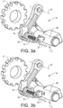
- Fig. 3a shows the wheel 17, the pawl 18 and the piston rod 22 of the hydraulic cylinder 40 for moving the pawl 18, when the pawl 18 and the wheel 17 are disengaged from each other.
- the parking lock mechanism 16 is not activated and the output shaft 3 is free to rotate.
- Fig. 3b which is similar to Fig. 3a , shows when the pawl 18 and the wheel 17 are engaged.
- the pawl 18 is pivotally arranged for movement about a pivot axis 25 for engagement and disengagement of the wheel 17 and the pawl 18.
- the pawl 18 is pivotally arranged at a fixed point of the transmission 1, such as the housing 19. See also Figs. 1 and 2 .
- the piston rod 22 the pawl 18 can be pivoted about the axis 25 relative to the wheel 17 between the disengaged position and the engaged position.
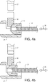
- Fig. 4a shows a cut side view of the components in Fig. 3a .
- the piston rod 22 has a conical end portion 23 which can be inserted between the pawl 18 and a guiding member 24 of the parking lock mechanism for pushing the pawl 18 into the engaged position.
- the guiding member 24 is a fixed point of the transmission 1 which is suitably attached to or constitutes a part of the housing 19.
- Fig. 4b which is similar to Fig. 4a , shows when the piston rod has been pushed (to the left in Fig. 4b ) into the space between the pawl 18 and the guiding member 24 such that the pawl 18 has been pivoted about the axis 25 to a position where the pawl 18 and the wheel 17 are engaged with each other.
- the movement direction 26 of the piston rod 22 is preferably substantially in parallel with the pivot axis 25 of the pawl 18. Further, the pivot axis 25 of the pawl 18 is suitably arranged substantially in parallel with the axial direction of the shaft 3 to which the wheel 17 is rotationally locked.
- Fig. 5 shows another example embodiment of the hydraulic cylinder in a schematic view.
- the cylinder portion 40' of the hydraulic cylinder is arranged in the valve block 20 and is optionally constituted by a part of the valve block.
- the piston rod 22 projects from the valve block 20.
- the piston rod 22 has an assembly position 28 for facilitating assembling of the valve block 20 together with the hydraulic cylinder into the transmission 1.
- the piston rod 22 is illustrated in this assembly position 28. In the assembly position there is a clearance space 27 between the end of the piston rod 22 and the guiding member 24.
- the assembly position 28 is provided for enabling the end portion 23 of the piston rod 22 to pass the guiding member 24 during assembling of the valve block 20.
- Fig. 6 is a schematic view showing an example of the piston rod 22 in the assembly position 28.
- the engaged position 29 and the disengaged position 30 are also indicated with dashed lines.
- the piston rod 22 can have locking positions for the engagement position 29, disengagement position 30 and the assembly position 28.
- the locking positions are achieved by corresponding slots 31, 32, 33 in the piston rod 22 and a blocking means 34 such as spring-loaded ball 35 to be received by such a slot 31, 32, 33.
- a first slot 31 for the locking position corresponding to the assembly position 28 a second slot 32 for the locking position corresponding the disengaged position 30 and a third slot 33 corresponding to the locking position for the engaged position 29.
- the locking position corresponding to the assembly position 28 constitutes the locking position where the piston rod 22 is most retracted (here to the right towards the valve block) for providing the clearance space 27 between the end of the piston rod 22 and the guiding member 24 as illustrated in Fig. 5 .
Landscapes
- Engineering & Computer Science (AREA)
- General Engineering & Computer Science (AREA)
- Mechanical Engineering (AREA)
- Transportation (AREA)
- Gear-Shifting Mechanisms (AREA)
Abstract
Description
- The invention relates to a transmission for a vehicle, which transmission has a parking lock mechanism.
- Vehicle transmissions usually have parking lock mechanisms with an actuation linkage system for engagement of a ratchet wheel and a pawl, for locking a shaft of the transmission.
- Such a parking lock mechanism requires small tolerances of several components and the assembling process is relatively complicated. Further, the packing space in the transmission is often very limited.
- An objective of the invention is to provide a transmission for a vehicle which transmission is less complicated and enables assembling of a parking lock mechanism to be simplified.
- The objective is achieved by a transmission for a vehicle, wherein the transmission comprises a housing and a valve block arranged in the housing, and a parking lock mechanism, and wherein the parking lock mechanism has a wheel rotationally locked to a shaft of the transmission, a pawl and a hydraulic actuator arranged for engagement of the wheel and the pawl for locking the shaft, and wherein the actuator is hydraulically connected to the valve block such that the actuator is supplied by hydraulic fluid from the valve block.
- The invention is based on the insight that by such a transmission, a simplified actuator of the parking lock mechanism can be used, where a linkage requiring small tolerances can be omitted.
- The actuator can be integrated in the valve block. Hereby, an increased available space outside the valve block can be achieved.
- By integrated in the valve block is meant that at least a part of the actuator is arranged in the valve block or directly attached to the valve block. For example, if the actuator is a hydraulic cylinder with a cylinder portion, a part of the valve block, such as a plate, can constitute the cylinder portion or the cylinder portion can be arranged inside the valve block or the cylinder portion can be attached to the valve block by a bolted joint.
- According to one embodiment of the transmission, the actuator is a hydraulic cylinder with a cylinder portion, a piston and a piston rod, wherein the hydraulic cylinder is arranged for moving the pawl between an engaged position and a disengaged position by means of the piston rod. Hereby, a small number of moving parts can used for providing the actuator.
- According to a further embodiment, in addition to an engaged position and a disengaged position, the piston rod has an assembly position for facilitating assembling of the valve block together with the hydraulic cylinder in the transmission. Hereby, the piston rod can be positioned in the assembly position to make the valve block with the hydraulic cylinder as compact as possible during the assembling procedure. For example, the piston rod can have locking positions for the engagement position, disengagement position and the assembly position, wherein the locking position for the assembly position constitutes the locking position where the piston rod is most retracted.
- According to a further embodiment, the piston rod has a conical end portion which can be inserted between the pawl and a guiding member of the parking lock mechanism for pushing the pawl into the engaged position. The guiding member can be attached to or constitute a part of the housing. Hereby, a reliable structure for engagement of the pawl and the wheel can be achieved.
- According to a further embodiment, the assembly position is arranged for enabling the end portion of the piston rod to pass the guiding member during assembling of the valve block together with the hydraulic cylinder in the transmission. Hereby, both a facilitated assembling procedure and a reliable structure for engagement of the pawl and the wheel can be achieved.
- According to a further embodiment, the pawl is pivotally arranged for movement about a pivot axis for engagement and disengagement of the wheel and the pawl, preferably the movement direction of the piston rod is substantially in parallel with the pivot axis of the pawl, and the pivot axis of the pawl is arranged substantially in parallel with the axial direction of the shaft to which the wheel is rotationally locked. Hereby, the compactness of the transmission can be further improved.
- Further advantages and advantageous features of the invention are disclosed in the following description and the claims.
- With reference to the appended drawings, below follows a more detailed description of embodiments of the invention cited as examples.
- In the drawings:
-
Fig. 1 is a schematic view showing a transmission for a vehicle, -
Fig. 2 is a side view of the transmission inFig. 1 , -
Fig. 3a is a perspective view showing a parking lock mechanism when disengaged, -
Fig. 3b is a perspective view showing a parking lock mechanism when engaged, -
Fig. 4a is a cut view showing the parking lock mechanism inFig. 3a , -
Fig. 4b is a cut view showing the parking lock mechanism inFig. 3b , -
Fig. 5 shows a parking lock mechanism with a piston rod of an actuator being in an assembly position, and -
Fig. 6 shows a piston rod and locking positions for the piston rod. -
Fig. 1 is a schematic view showing atransmission 1 for a vehicle. The transmission has aninput shaft 2 and anoutput shaft 3. Theinput shaft 2 and theoutput shaft 3 are connected to each other bygear wheels 4. For example, afirst gear wheel 5 of theinput shaft 2 is engaged with afirst gear wheel 6 of theoutput shaft 3, and asecond gear wheel 7 of theinput shaft 2 is engaged with asecond gear wheel 8 of theoutput shaft 3. Thegear wheels output shaft 3 can be idle wheels, i.e. thesegear wheels output shaft 3 but can be rotationally locked to the output shaft by asynchronizer 9. By movement of asynchronizer sleeve 10 in a first direction, thefirst gear wheel 6 of theoutput shaft 3 is rotationally locked to theoutput shaft 3. By movement of thesynchronizer sleeve 10 in a second opposite direction, thesecond gearwheel 8 of theoutput shaft 3 is rotationally locked to theoutput shaft 3. Thus, one gear is represented by thefirst gear wheel 5 of theinput shaft 2 and thefirst gear wheel 6 of theoutput shaft 3. A further gear is represented by thesecond gear wheel 7 of theinput shaft 2 and thesecond gear wheel 8 theoutput shaft 3. - The
input shaft 2 can be driven by amotor 11. Themotor 11 can be any suitable motor, such an internal combustion engine, electric motor, etc. Between themotor 11 and thetransmission 1, aclutch 12 is suitably arranged for enabling thetransmission 1 to be connected or disconnected to/from themotor 11. - In the example embodiment illustrated in
Fig. 1 , theoutput shaft 3 has anoutput gear wheel 13. Theoutput gear wheel 13 is rotationally locked to theoutput shaft 3 and is engaged with aring gear wheel 14 of adifferential device 15, thereby connecting theoutput shaft 3 to thering gear wheel 14. Thedifferential device 15 is in turn suitably conventionally connected to the driven wheels of a vehicle (not shown). - As schematically indicated in
Fig. 1 , thetransmission 1 comprises aparking lock mechanism 16. Theparking lock mechanism 16 has awheel 17, such as a gear wheel or ratchet wheel rotationally locked to ashaft 3 of thetransmission 1. In the example embodiment illustrated inFig. 1 , thewheel 17 is arranged on theoutput shaft 3. Thetransmission 1 comprises also apawl 18 and a hydraulic actuator (not shown inFig. 1 ) for engagement of thewheel 17 and thepawl 18 for locking theoutput shaft 3 against rotation. Thus, thewheel 17 and thepawl 18 can be engaged and disengaged to/from each other. When thewheel 17 and thepawl 18 are engaged with each other, theoutput shaft 3 is locked to ahousing 19 of the transmission. -
Fig. 2 is a schematic side view of thetransmission 1 showing theinput shaft 2, theoutput shaft 3 and thering gear wheel 14 of thedifferential device 15.Fig. 2 is partly cut for showing thewheel 17 and thepawl 18. Thetransmission 1 has ahousing 19 and avalve block 20 arranged in the housing. - The
valve block 20 comprises hydraulic valves (not shown) for controlling components of thetransmission 1. For example, valves for controlling the clutch 12, thesynchronizer sleeve 10 and for cooling and lubrication of thetransmission 1 can be arranged in thevalve block 20. - The
actuator 21 is hydraulically connected to thevalve block 20, i.e. to a hydraulic connection such as a pipe or a valve of the valve block, such that theactuator 21 is supplied by hydraulic fluid from the valve block. - In the example embodiment illustrated in
Fig. 2 , theactuator 21 for engagement and disengagement of thewheel 17 and thepawl 18 is integrated in thevalve block 20, as schematically indicated inFig. 2 . - The
actuator 21 is suitably a hydraulic cylinder with a cylinder portion, a piston and a piston rod, for moving thepawl 18 between an engaged position and a disengaged position by means of the piston rod. The cylinder portion of thehydraulic cylinder 21 is arranged in thevalve block 20. -
Fig. 3a shows thewheel 17, thepawl 18 and thepiston rod 22 of thehydraulic cylinder 40 for moving thepawl 18, when thepawl 18 and thewheel 17 are disengaged from each other. Thus, theparking lock mechanism 16 is not activated and theoutput shaft 3 is free to rotate.Fig. 3b , which is similar toFig. 3a , shows when thepawl 18 and thewheel 17 are engaged. Thus, theparking lock mechanism 16 is activated and theoutput shaft 3 is locked against rotation. Thepawl 18 is pivotally arranged for movement about apivot axis 25 for engagement and disengagement of thewheel 17 and thepawl 18. Thepawl 18 is pivotally arranged at a fixed point of thetransmission 1, such as thehousing 19. See alsoFigs. 1 and2 . By means of thepiston rod 22 thepawl 18 can be pivoted about theaxis 25 relative to thewheel 17 between the disengaged position and the engaged position. -
Fig. 4a shows a cut side view of the components inFig. 3a . Thepiston rod 22 has aconical end portion 23 which can be inserted between thepawl 18 and a guidingmember 24 of the parking lock mechanism for pushing thepawl 18 into the engaged position. The guidingmember 24 is a fixed point of thetransmission 1 which is suitably attached to or constitutes a part of thehousing 19.Fig. 4b , which is similar toFig. 4a , shows when the piston rod has been pushed (to the left inFig. 4b ) into the space between thepawl 18 and the guidingmember 24 such that thepawl 18 has been pivoted about theaxis 25 to a position where thepawl 18 and thewheel 17 are engaged with each other. - The
movement direction 26 of thepiston rod 22 is preferably substantially in parallel with thepivot axis 25 of thepawl 18. Further, thepivot axis 25 of thepawl 18 is suitably arranged substantially in parallel with the axial direction of theshaft 3 to which thewheel 17 is rotationally locked. -
Fig. 5 shows another example embodiment of the hydraulic cylinder in a schematic view. The cylinder portion 40' of the hydraulic cylinder is arranged in thevalve block 20 and is optionally constituted by a part of the valve block. Thepiston rod 22 projects from thevalve block 20. In addition to the engaged position (illustrated inFig. 4b ) and the disengaged position (illustrated inFig. 4a ), thepiston rod 22 has anassembly position 28 for facilitating assembling of thevalve block 20 together with the hydraulic cylinder into thetransmission 1. InFig. 5 , thepiston rod 22 is illustrated in thisassembly position 28. In the assembly position there is aclearance space 27 between the end of thepiston rod 22 and the guidingmember 24. Theassembly position 28 is provided for enabling theend portion 23 of thepiston rod 22 to pass the guidingmember 24 during assembling of thevalve block 20. -
Fig. 6 is a schematic view showing an example of thepiston rod 22 in theassembly position 28. The engagedposition 29 and thedisengaged position 30 are also indicated with dashed lines. Thepiston rod 22 can have locking positions for theengagement position 29,disengagement position 30 and theassembly position 28. In the example embodiment illustrated inFig. 6 , the locking positions are achieved by correspondingslots piston rod 22 and a blocking means 34 such as spring-loadedball 35 to be received by such aslot first slot 31 for the locking position corresponding to theassembly position 28, asecond slot 32 for the locking position corresponding thedisengaged position 30 and athird slot 33 corresponding to the locking position for the engagedposition 29. The locking position corresponding to theassembly position 28 constitutes the locking position where thepiston rod 22 is most retracted (here to the right towards the valve block) for providing theclearance space 27 between the end of thepiston rod 22 and the guidingmember 24 as illustrated inFig. 5 . - It is to be understood that the present invention is not limited to the embodiments described above and illustrated in the drawings; rather, the skilled person will recognize that many changes and modifications may be made within the scope of the appended claims.
Claims (15)
- A transmission for a vehicle, the transmission (1) comprising a housing (19) and a valve block (20) arranged in the housing, and a parking lock mechanism (16), the parking lock mechanism having a wheel (17) rotationally locked to a shaft (3) of the transmission, a pawl (18) and a hydraulic actuator (21) arranged for engagement of the wheel and the pawl for locking the shaft (3), characterized in that the actuator is hydraulically connected to the valve block such that the actuator is supplied by hydraulic fluid from the valve block.
- A transmission according to claim 1, characterized in that the actuator (21) is integrated in the valve block (20).
- A transmission according to claim 1 or 2, characterized in that the actuator (21) is a hydraulic cylinder (40) with a cylinder portion, a piston and a piston rod (22), the hydraulic cylinder being arranged for moving the pawl (18) between an engaged position and a disengaged position by means of the piston rod (22).
- A transmission according to claim 2 and 3, characterized in that the cylinder portion of the hydraulic cylinder is arranged in the valve block (20).
- A transmission according to claim 4, characterized in that a part of the valve block constitutes the cylinder portion of the hydraulic cylinder.
- A transmission according to claim 2 and 3, characterized in that the cylinder portion of the hydraulic cylinder is attached to the valve block by a bolted joint.
- A transmission according to any of claims 3-6, characterized in that in addition to an engaged position (29) and a disengaged position (30), the piston rod (22) has an assembly position (28) for facilitating assembling of the valve block (20) together with the hydraulic cylinder in the transmission (1).
- A transmission according to claim 7, characterized in that the piston rod (22) has locking positions (31, 32, 33) for the engagement position, disengagement position and assembly position, the locking position (31) for the assembly position (28) constituting the locking position where the piston rod (22) is most retracted.
- A transmission according to any of claims 3-8, characterized in that the piston rod (22) has a conical end portion (23) which can be inserted between the pawl (18) and a guiding member (24) of the parking lock mechanism (21) for pushing the pawl (18) into the engaged position.
- A transmission according to claim 9, characterized in that the guiding member (24) is attached to or constitute a part of the housing (19).
- A transmission according to claim 3 and 7, characterized in that the assembly position (28) is arranged for enabling the end portion of the piston rod (22) to pass the guiding member (24) during assembling of the valve block (20) together with the hydraulic cylinder in the transmission.
- A transmission according to any preceding claim, characterized in that the pawl (18) is pivotally arranged for movement about a pivot axis (25) for engagement and disengagement of the wheel (17) and the pawl (18).
- A transmission according to claim 12, characterized in that the pivot axis (25) of the pawl (18) is arranged substantially in parallel with the axial direction of the shaft (3) to which the wheel (17) is rotationally locked.
- A transmission according to claim 3 and 12, characterized in that the movement direction (26) of the piston rod (22) is substantially in parallel with the pivot axis (25) of the pawl (18).
- A transmission according to any preceding claim, characterized in that the valve block is arranged for controlling a clutch and/or one or more gears and/or a cooling and lubrication device of the transmission.
Priority Applications (4)
| Application Number | Priority Date | Filing Date | Title |
|---|---|---|---|
| EP18212982.5A EP3670970B1 (en) | 2018-12-17 | 2018-12-17 | A transmission for a vehicle |
| CN201980081272.XA CN113167381B (en) | 2018-12-17 | 2019-11-25 | Transmission for vehicle |
| PCT/CN2019/120495 WO2020125327A1 (en) | 2018-12-17 | 2019-11-25 | A transmission for a vehicle |
| US17/325,782 US11543028B2 (en) | 2018-12-17 | 2021-05-20 | Transmission for a vehicle |
Applications Claiming Priority (1)
| Application Number | Priority Date | Filing Date | Title |
|---|---|---|---|
| EP18212982.5A EP3670970B1 (en) | 2018-12-17 | 2018-12-17 | A transmission for a vehicle |
Publications (2)
| Publication Number | Publication Date |
|---|---|
| EP3670970A1 true EP3670970A1 (en) | 2020-06-24 |
| EP3670970B1 EP3670970B1 (en) | 2022-05-04 |
Family
ID=64744399
Family Applications (1)
| Application Number | Title | Priority Date | Filing Date |
|---|---|---|---|
| EP18212982.5A Active EP3670970B1 (en) | 2018-12-17 | 2018-12-17 | A transmission for a vehicle |
Country Status (4)
| Country | Link |
|---|---|
| US (1) | US11543028B2 (en) |
| EP (1) | EP3670970B1 (en) |
| CN (1) | CN113167381B (en) |
| WO (1) | WO2020125327A1 (en) |
Families Citing this family (2)
| Publication number | Priority date | Publication date | Assignee | Title |
|---|---|---|---|---|
| US11821512B2 (en) * | 2019-11-28 | 2023-11-21 | Jatco Ltd | Park lock mechanism |
| DE102022119866A1 (en) * | 2022-08-08 | 2024-02-08 | Schaeffler Technologies AG & Co. KG | Parking lock for a vehicle transmission |
Citations (6)
| Publication number | Priority date | Publication date | Assignee | Title |
|---|---|---|---|---|
| US20040248687A1 (en) * | 2003-06-03 | 2004-12-09 | Powell Stephen W. | Park solenoid assembly for an internal electronic transmission range selection (ETRS) system |
| US20070191182A1 (en) * | 2006-02-13 | 2007-08-16 | Koski Jack P | Park inhibit assembly for an electric transmission range selection system |
| US20100269620A1 (en) * | 2009-04-23 | 2010-10-28 | Hyundai Motor Company | Parking Brake Apparatus |
| US20170016533A1 (en) * | 2015-07-16 | 2017-01-19 | GM Global Technology Operations LLC | Hydraulic park gear assembly |
| US20180135752A1 (en) * | 2016-11-17 | 2018-05-17 | GM Global Technology Operations LLC | Vehicle |
| WO2018192989A1 (en) * | 2017-04-18 | 2018-10-25 | Punch Powertrain N.V. | A hydraulic system for a vehicle, a vehicle transmission, and method for operating a vehicle transmission |
Family Cites Families (16)
| Publication number | Priority date | Publication date | Assignee | Title |
|---|---|---|---|---|
| US6701797B2 (en) * | 2001-01-04 | 2004-03-09 | Ford Global Technologies, Llc | Parking assembly |
| DE102009005753A1 (en) * | 2009-01-23 | 2010-07-29 | Daimler Ag | Hydraulic control for an automated transmission |
| US20140097363A1 (en) * | 2012-10-05 | 2014-04-10 | Array Holdings, Inc. | Floating seal retainer |
| US9958066B2 (en) * | 2014-01-23 | 2018-05-01 | Aisin Aw Co., Ltd. | Range switching device |
| US9255640B1 (en) * | 2014-09-03 | 2016-02-09 | E-Aam Driveline Systems Ab | Park lock mechanism |
| CN204358079U (en) * | 2014-12-03 | 2015-05-27 | 惠州比亚迪电池有限公司 | Control device and there is the vehicle of control device |
| US10041591B2 (en) * | 2015-07-13 | 2018-08-07 | Ford Global Technologies, Llc | Transmission park mechanism |
| JP6603601B2 (en) * | 2016-03-17 | 2019-11-06 | 本田技研工業株式会社 | Parking lock device for vehicle |
| DE102016014523A1 (en) * | 2016-12-07 | 2018-06-07 | Fte Automotive Gmbh | Electric parking brake actuator for actuating a parking brake in a motor vehicle |
| FR3063324A1 (en) * | 2017-02-27 | 2018-08-31 | Peugeot Citroen Automobiles Sa | HYDRAULIC LOCKING PARKING LOCK FOR A MOTOR VEHICLE TRANSMISSION |
| FR3063323B1 (en) * | 2017-02-27 | 2020-10-30 | Peugeot Citroen Automobiles Sa | MECHANICAL LOCKING PARKING LOCK FOR A MOTOR VEHICLE TRANSMISSION |
| US10900565B2 (en) * | 2017-05-11 | 2021-01-26 | Fca Us Llc | Lost motion transmission shifter |
| CN206889662U (en) * | 2017-07-21 | 2018-01-16 | 长城汽车股份有限公司 | Parking device, speed changer and the vehicle of speed changer |
| CN208041118U (en) * | 2017-12-26 | 2018-11-02 | 长城汽车股份有限公司 | The speed changer of vehicle hydraulic pressure halting mechanism and with its vehicle |
| FR3079902B1 (en) * | 2018-04-10 | 2020-03-13 | Psa Automobiles Sa | PARKING LOCK CONTROL SYSTEM |
| JP6725615B2 (en) * | 2018-09-21 | 2020-07-22 | 株式会社Subaru | Parking lock device |
-
2018
- 2018-12-17 EP EP18212982.5A patent/EP3670970B1/en active Active
-
2019
- 2019-11-25 CN CN201980081272.XA patent/CN113167381B/en active Active
- 2019-11-25 WO PCT/CN2019/120495 patent/WO2020125327A1/en not_active Ceased
-
2021
- 2021-05-20 US US17/325,782 patent/US11543028B2/en active Active
Patent Citations (6)
| Publication number | Priority date | Publication date | Assignee | Title |
|---|---|---|---|---|
| US20040248687A1 (en) * | 2003-06-03 | 2004-12-09 | Powell Stephen W. | Park solenoid assembly for an internal electronic transmission range selection (ETRS) system |
| US20070191182A1 (en) * | 2006-02-13 | 2007-08-16 | Koski Jack P | Park inhibit assembly for an electric transmission range selection system |
| US20100269620A1 (en) * | 2009-04-23 | 2010-10-28 | Hyundai Motor Company | Parking Brake Apparatus |
| US20170016533A1 (en) * | 2015-07-16 | 2017-01-19 | GM Global Technology Operations LLC | Hydraulic park gear assembly |
| US20180135752A1 (en) * | 2016-11-17 | 2018-05-17 | GM Global Technology Operations LLC | Vehicle |
| WO2018192989A1 (en) * | 2017-04-18 | 2018-10-25 | Punch Powertrain N.V. | A hydraulic system for a vehicle, a vehicle transmission, and method for operating a vehicle transmission |
Also Published As
| Publication number | Publication date |
|---|---|
| EP3670970B1 (en) | 2022-05-04 |
| WO2020125327A1 (en) | 2020-06-25 |
| US20210285542A1 (en) | 2021-09-16 |
| US11543028B2 (en) | 2023-01-03 |
| CN113167381A (en) | 2021-07-23 |
| CN113167381B (en) | 2023-03-21 |
Similar Documents
| Publication | Publication Date | Title |
|---|---|---|
| US6607060B2 (en) | Clutch operating system and a hydraulic mechanism used in the same | |
| CN110030377B (en) | Shift-by-wire parking system | |
| US20110283830A1 (en) | Concentric slave cylinders to actuate clutches on a dual clutch transmission | |
| EP3658802B1 (en) | Shift control arrangement in a gearbox | |
| EP3921562B1 (en) | System for activating a park lock | |
| EP2886911A1 (en) | Spring loaded shift actuator assembly having a retaining mechanism | |
| US6712189B2 (en) | Torque transfer device with release mechanism | |
| US11543028B2 (en) | Transmission for a vehicle | |
| US9194485B2 (en) | Shift system for power transfer unit having dual sector shift actuator | |
| US10900565B2 (en) | Lost motion transmission shifter | |
| US11859719B2 (en) | Parking lock device | |
| CN115030995A (en) | Module for a system for synchronizing and driving the countershafts of a gearbox of a transmission | |
| US12163586B2 (en) | Transmission | |
| CN105659008B (en) | Operating device with master cylinder actuatable by means of a shift drum for actuating a clutch | |
| EP4261438A1 (en) | Actuation system for the actuation of movement elements of a gearbox and arrangement for a gearbox comprising the actuation system | |
| CN114746663B (en) | Actuator system for a vehicle transmission, vehicle comprising the actuator system, and method for operating the actuator system | |
| EP2831471B1 (en) | A piston pin assembly | |
| CN112912638B (en) | Countershaft assembly used in vehicle transmission | |
| US10753468B2 (en) | Auxiliary transmission actuation mechanism in a manual dual clutch power transmission unit of a vehicle | |
| KR20060058440A (en) | Parking system of transmission | |
| JP2001032930A (en) | Reverse shift limiting device for manual transmission | |
| KR20070038457A (en) | clutch | |
| DE102018117931A1 (en) | Switching device for a gear arrangement and gear arrangement with the switching device |
Legal Events
| Date | Code | Title | Description |
|---|---|---|---|
| PUAI | Public reference made under article 153(3) epc to a published international application that has entered the european phase |
Free format text: ORIGINAL CODE: 0009012 |
|
| STAA | Information on the status of an ep patent application or granted ep patent |
Free format text: STATUS: REQUEST FOR EXAMINATION WAS MADE |
|
| 17P | Request for examination filed |
Effective date: 20181217 |
|
| AK | Designated contracting states |
Kind code of ref document: A1 Designated state(s): AL AT BE BG CH CY CZ DE DK EE ES FI FR GB GR HR HU IE IS IT LI LT LU LV MC MK MT NL NO PL PT RO RS SE SI SK SM TR |
|
| AX | Request for extension of the european patent |
Extension state: BA ME |
|
| STAA | Information on the status of an ep patent application or granted ep patent |
Free format text: STATUS: EXAMINATION IS IN PROGRESS |
|
| 17Q | First examination report despatched |
Effective date: 20210316 |
|
| GRAP | Despatch of communication of intention to grant a patent |
Free format text: ORIGINAL CODE: EPIDOSNIGR1 |
|
| STAA | Information on the status of an ep patent application or granted ep patent |
Free format text: STATUS: GRANT OF PATENT IS INTENDED |
|
| INTG | Intention to grant announced |
Effective date: 20220110 |
|
| GRAS | Grant fee paid |
Free format text: ORIGINAL CODE: EPIDOSNIGR3 |
|
| GRAA | (expected) grant |
Free format text: ORIGINAL CODE: 0009210 |
|
| STAA | Information on the status of an ep patent application or granted ep patent |
Free format text: STATUS: THE PATENT HAS BEEN GRANTED |
|
| AK | Designated contracting states |
Kind code of ref document: B1 Designated state(s): AL AT BE BG CH CY CZ DE DK EE ES FI FR GB GR HR HU IE IS IT LI LT LU LV MC MK MT NL NO PL PT RO RS SE SI SK SM TR |
|
| REG | Reference to a national code |
Ref country code: GB Ref legal event code: FG4D |
|
| REG | Reference to a national code |
Ref country code: CH Ref legal event code: EP |
|
| REG | Reference to a national code |
Ref country code: AT Ref legal event code: REF Ref document number: 1489365 Country of ref document: AT Kind code of ref document: T Effective date: 20220515 |
|
| REG | Reference to a national code |
Ref country code: IE Ref legal event code: FG4D Ref country code: DE Ref legal event code: R096 Ref document number: 602018034856 Country of ref document: DE |
|
| REG | Reference to a national code |
Ref country code: LT Ref legal event code: MG9D |
|
| REG | Reference to a national code |
Ref country code: NL Ref legal event code: MP Effective date: 20220504 |
|
| REG | Reference to a national code |
Ref country code: AT Ref legal event code: MK05 Ref document number: 1489365 Country of ref document: AT Kind code of ref document: T Effective date: 20220504 |
|
| PG25 | Lapsed in a contracting state [announced via postgrant information from national office to epo] |
Ref country code: SE Free format text: LAPSE BECAUSE OF FAILURE TO SUBMIT A TRANSLATION OF THE DESCRIPTION OR TO PAY THE FEE WITHIN THE PRESCRIBED TIME-LIMIT Effective date: 20220504 Ref country code: PT Free format text: LAPSE BECAUSE OF FAILURE TO SUBMIT A TRANSLATION OF THE DESCRIPTION OR TO PAY THE FEE WITHIN THE PRESCRIBED TIME-LIMIT Effective date: 20220905 Ref country code: NO Free format text: LAPSE BECAUSE OF FAILURE TO SUBMIT A TRANSLATION OF THE DESCRIPTION OR TO PAY THE FEE WITHIN THE PRESCRIBED TIME-LIMIT Effective date: 20220804 Ref country code: NL Free format text: LAPSE BECAUSE OF FAILURE TO SUBMIT A TRANSLATION OF THE DESCRIPTION OR TO PAY THE FEE WITHIN THE PRESCRIBED TIME-LIMIT Effective date: 20220504 Ref country code: LT Free format text: LAPSE BECAUSE OF FAILURE TO SUBMIT A TRANSLATION OF THE DESCRIPTION OR TO PAY THE FEE WITHIN THE PRESCRIBED TIME-LIMIT Effective date: 20220504 Ref country code: HR Free format text: LAPSE BECAUSE OF FAILURE TO SUBMIT A TRANSLATION OF THE DESCRIPTION OR TO PAY THE FEE WITHIN THE PRESCRIBED TIME-LIMIT Effective date: 20220504 Ref country code: GR Free format text: LAPSE BECAUSE OF FAILURE TO SUBMIT A TRANSLATION OF THE DESCRIPTION OR TO PAY THE FEE WITHIN THE PRESCRIBED TIME-LIMIT Effective date: 20220805 Ref country code: FI Free format text: LAPSE BECAUSE OF FAILURE TO SUBMIT A TRANSLATION OF THE DESCRIPTION OR TO PAY THE FEE WITHIN THE PRESCRIBED TIME-LIMIT Effective date: 20220504 Ref country code: ES Free format text: LAPSE BECAUSE OF FAILURE TO SUBMIT A TRANSLATION OF THE DESCRIPTION OR TO PAY THE FEE WITHIN THE PRESCRIBED TIME-LIMIT Effective date: 20220504 Ref country code: BG Free format text: LAPSE BECAUSE OF FAILURE TO SUBMIT A TRANSLATION OF THE DESCRIPTION OR TO PAY THE FEE WITHIN THE PRESCRIBED TIME-LIMIT Effective date: 20220804 Ref country code: AT Free format text: LAPSE BECAUSE OF FAILURE TO SUBMIT A TRANSLATION OF THE DESCRIPTION OR TO PAY THE FEE WITHIN THE PRESCRIBED TIME-LIMIT Effective date: 20220504 |
|
| PG25 | Lapsed in a contracting state [announced via postgrant information from national office to epo] |
Ref country code: RS Free format text: LAPSE BECAUSE OF FAILURE TO SUBMIT A TRANSLATION OF THE DESCRIPTION OR TO PAY THE FEE WITHIN THE PRESCRIBED TIME-LIMIT Effective date: 20220504 Ref country code: PL Free format text: LAPSE BECAUSE OF FAILURE TO SUBMIT A TRANSLATION OF THE DESCRIPTION OR TO PAY THE FEE WITHIN THE PRESCRIBED TIME-LIMIT Effective date: 20220504 Ref country code: LV Free format text: LAPSE BECAUSE OF FAILURE TO SUBMIT A TRANSLATION OF THE DESCRIPTION OR TO PAY THE FEE WITHIN THE PRESCRIBED TIME-LIMIT Effective date: 20220504 Ref country code: IS Free format text: LAPSE BECAUSE OF FAILURE TO SUBMIT A TRANSLATION OF THE DESCRIPTION OR TO PAY THE FEE WITHIN THE PRESCRIBED TIME-LIMIT Effective date: 20220904 |
|
| PG25 | Lapsed in a contracting state [announced via postgrant information from national office to epo] |
Ref country code: SM Free format text: LAPSE BECAUSE OF FAILURE TO SUBMIT A TRANSLATION OF THE DESCRIPTION OR TO PAY THE FEE WITHIN THE PRESCRIBED TIME-LIMIT Effective date: 20220504 Ref country code: SK Free format text: LAPSE BECAUSE OF FAILURE TO SUBMIT A TRANSLATION OF THE DESCRIPTION OR TO PAY THE FEE WITHIN THE PRESCRIBED TIME-LIMIT Effective date: 20220504 Ref country code: RO Free format text: LAPSE BECAUSE OF FAILURE TO SUBMIT A TRANSLATION OF THE DESCRIPTION OR TO PAY THE FEE WITHIN THE PRESCRIBED TIME-LIMIT Effective date: 20220504 Ref country code: EE Free format text: LAPSE BECAUSE OF FAILURE TO SUBMIT A TRANSLATION OF THE DESCRIPTION OR TO PAY THE FEE WITHIN THE PRESCRIBED TIME-LIMIT Effective date: 20220504 Ref country code: DK Free format text: LAPSE BECAUSE OF FAILURE TO SUBMIT A TRANSLATION OF THE DESCRIPTION OR TO PAY THE FEE WITHIN THE PRESCRIBED TIME-LIMIT Effective date: 20220504 Ref country code: CZ Free format text: LAPSE BECAUSE OF FAILURE TO SUBMIT A TRANSLATION OF THE DESCRIPTION OR TO PAY THE FEE WITHIN THE PRESCRIBED TIME-LIMIT Effective date: 20220504 |
|
| REG | Reference to a national code |
Ref country code: DE Ref legal event code: R097 Ref document number: 602018034856 Country of ref document: DE |
|
| PLBE | No opposition filed within time limit |
Free format text: ORIGINAL CODE: 0009261 |
|
| STAA | Information on the status of an ep patent application or granted ep patent |
Free format text: STATUS: NO OPPOSITION FILED WITHIN TIME LIMIT |
|
| PG25 | Lapsed in a contracting state [announced via postgrant information from national office to epo] |
Ref country code: AL Free format text: LAPSE BECAUSE OF FAILURE TO SUBMIT A TRANSLATION OF THE DESCRIPTION OR TO PAY THE FEE WITHIN THE PRESCRIBED TIME-LIMIT Effective date: 20220504 |
|
| 26N | No opposition filed |
Effective date: 20230207 |
|
| PG25 | Lapsed in a contracting state [announced via postgrant information from national office to epo] |
Ref country code: SI Free format text: LAPSE BECAUSE OF FAILURE TO SUBMIT A TRANSLATION OF THE DESCRIPTION OR TO PAY THE FEE WITHIN THE PRESCRIBED TIME-LIMIT Effective date: 20220504 |
|
| REG | Reference to a national code |
Ref country code: CH Ref legal event code: PL |
|
| REG | Reference to a national code |
Ref country code: BE Ref legal event code: MM Effective date: 20221231 |
|
| PG25 | Lapsed in a contracting state [announced via postgrant information from national office to epo] |
Ref country code: LU Free format text: LAPSE BECAUSE OF NON-PAYMENT OF DUE FEES Effective date: 20221217 |
|
| PG25 | Lapsed in a contracting state [announced via postgrant information from national office to epo] |
Ref country code: LI Free format text: LAPSE BECAUSE OF NON-PAYMENT OF DUE FEES Effective date: 20221231 Ref country code: IE Free format text: LAPSE BECAUSE OF NON-PAYMENT OF DUE FEES Effective date: 20221217 Ref country code: CH Free format text: LAPSE BECAUSE OF NON-PAYMENT OF DUE FEES Effective date: 20221231 |
|
| PG25 | Lapsed in a contracting state [announced via postgrant information from national office to epo] |
Ref country code: BE Free format text: LAPSE BECAUSE OF NON-PAYMENT OF DUE FEES Effective date: 20221231 |
|
| PG25 | Lapsed in a contracting state [announced via postgrant information from national office to epo] |
Ref country code: IT Free format text: LAPSE BECAUSE OF FAILURE TO SUBMIT A TRANSLATION OF THE DESCRIPTION OR TO PAY THE FEE WITHIN THE PRESCRIBED TIME-LIMIT Effective date: 20220504 |
|
| PG25 | Lapsed in a contracting state [announced via postgrant information from national office to epo] |
Ref country code: HU Free format text: LAPSE BECAUSE OF FAILURE TO SUBMIT A TRANSLATION OF THE DESCRIPTION OR TO PAY THE FEE WITHIN THE PRESCRIBED TIME-LIMIT; INVALID AB INITIO Effective date: 20181217 |
|
| PG25 | Lapsed in a contracting state [announced via postgrant information from national office to epo] |
Ref country code: CY Free format text: LAPSE BECAUSE OF FAILURE TO SUBMIT A TRANSLATION OF THE DESCRIPTION OR TO PAY THE FEE WITHIN THE PRESCRIBED TIME-LIMIT Effective date: 20220504 |
|
| PG25 | Lapsed in a contracting state [announced via postgrant information from national office to epo] |
Ref country code: MK Free format text: LAPSE BECAUSE OF FAILURE TO SUBMIT A TRANSLATION OF THE DESCRIPTION OR TO PAY THE FEE WITHIN THE PRESCRIBED TIME-LIMIT Effective date: 20220504 |
|
| PG25 | Lapsed in a contracting state [announced via postgrant information from national office to epo] |
Ref country code: MC Free format text: LAPSE BECAUSE OF FAILURE TO SUBMIT A TRANSLATION OF THE DESCRIPTION OR TO PAY THE FEE WITHIN THE PRESCRIBED TIME-LIMIT Effective date: 20220504 |
|
| PG25 | Lapsed in a contracting state [announced via postgrant information from national office to epo] |
Ref country code: TR Free format text: LAPSE BECAUSE OF FAILURE TO SUBMIT A TRANSLATION OF THE DESCRIPTION OR TO PAY THE FEE WITHIN THE PRESCRIBED TIME-LIMIT Effective date: 20220504 Ref country code: MC Free format text: LAPSE BECAUSE OF FAILURE TO SUBMIT A TRANSLATION OF THE DESCRIPTION OR TO PAY THE FEE WITHIN THE PRESCRIBED TIME-LIMIT Effective date: 20220504 |
|
| PG25 | Lapsed in a contracting state [announced via postgrant information from national office to epo] |
Ref country code: MT Free format text: LAPSE BECAUSE OF FAILURE TO SUBMIT A TRANSLATION OF THE DESCRIPTION OR TO PAY THE FEE WITHIN THE PRESCRIBED TIME-LIMIT Effective date: 20220504 |
|
| PG25 | Lapsed in a contracting state [announced via postgrant information from national office to epo] |
Ref country code: BG Free format text: LAPSE BECAUSE OF FAILURE TO SUBMIT A TRANSLATION OF THE DESCRIPTION OR TO PAY THE FEE WITHIN THE PRESCRIBED TIME-LIMIT Effective date: 20220504 |
|
| PG25 | Lapsed in a contracting state [announced via postgrant information from national office to epo] |
Ref country code: BG Free format text: LAPSE BECAUSE OF FAILURE TO SUBMIT A TRANSLATION OF THE DESCRIPTION OR TO PAY THE FEE WITHIN THE PRESCRIBED TIME-LIMIT Effective date: 20220504 |
|
| PGFP | Annual fee paid to national office [announced via postgrant information from national office to epo] |
Ref country code: GB Payment date: 20251104 Year of fee payment: 8 |
|
| PGFP | Annual fee paid to national office [announced via postgrant information from national office to epo] |
Ref country code: FR Payment date: 20251117 Year of fee payment: 8 |
|
| PGFP | Annual fee paid to national office [announced via postgrant information from national office to epo] |
Ref country code: DE Payment date: 20251222 Year of fee payment: 8 |