EP3670686A1 - Battery recycling process - Google Patents
Battery recycling process Download PDFInfo
- Publication number
- EP3670686A1 EP3670686A1 EP19161012.0A EP19161012A EP3670686A1 EP 3670686 A1 EP3670686 A1 EP 3670686A1 EP 19161012 A EP19161012 A EP 19161012A EP 3670686 A1 EP3670686 A1 EP 3670686A1
- Authority
- EP
- European Patent Office
- Prior art keywords
- stage
- leach solution
- pregnant leach
- extractant
- solvent extraction
- Prior art date
- Legal status (The legal status is an assumption and is not a legal conclusion. Google has not performed a legal analysis and makes no representation as to the accuracy of the status listed.)
- Withdrawn
Links
- 238000000034 method Methods 0.000 title claims abstract description 61
- 230000008569 process Effects 0.000 title claims description 20
- 238000004064 recycling Methods 0.000 title description 7
- PXHVJJICTQNCMI-UHFFFAOYSA-N Nickel Chemical compound [Ni] PXHVJJICTQNCMI-UHFFFAOYSA-N 0.000 claims abstract description 126
- 238000000638 solvent extraction Methods 0.000 claims abstract description 118
- QAOWNCQODCNURD-UHFFFAOYSA-N Sulfuric acid Chemical compound OS(O)(=O)=O QAOWNCQODCNURD-UHFFFAOYSA-N 0.000 claims abstract description 109
- 239000010941 cobalt Substances 0.000 claims abstract description 73
- GUTLYIVDDKVIGB-UHFFFAOYSA-N cobalt atom Chemical compound [Co] GUTLYIVDDKVIGB-UHFFFAOYSA-N 0.000 claims abstract description 73
- 229910052751 metal Inorganic materials 0.000 claims abstract description 73
- 239000002184 metal Substances 0.000 claims abstract description 73
- 235000011149 sulphuric acid Nutrition 0.000 claims abstract description 73
- 229910017052 cobalt Inorganic materials 0.000 claims abstract description 72
- 238000011084 recovery Methods 0.000 claims abstract description 70
- 239000007787 solid Chemical group 0.000 claims abstract description 70
- 239000001117 sulphuric acid Substances 0.000 claims abstract description 70
- 239000010949 copper Substances 0.000 claims abstract description 66
- RYGMFSIKBFXOCR-UHFFFAOYSA-N Copper Chemical compound [Cu] RYGMFSIKBFXOCR-UHFFFAOYSA-N 0.000 claims abstract description 65
- 229910052802 copper Inorganic materials 0.000 claims abstract description 65
- 239000004411 aluminium Substances 0.000 claims abstract description 63
- 229910052782 aluminium Inorganic materials 0.000 claims abstract description 63
- 229910052759 nickel Inorganic materials 0.000 claims abstract description 62
- XAGFODPZIPBFFR-UHFFFAOYSA-N aluminium Chemical compound [Al] XAGFODPZIPBFFR-UHFFFAOYSA-N 0.000 claims abstract description 61
- WHXSMMKQMYFTQS-UHFFFAOYSA-N Lithium Chemical compound [Li] WHXSMMKQMYFTQS-UHFFFAOYSA-N 0.000 claims abstract description 54
- 229910052744 lithium Inorganic materials 0.000 claims abstract description 54
- 239000002002 slurry Substances 0.000 claims abstract description 49
- 150000002739 metals Chemical class 0.000 claims abstract description 40
- 150000003839 salts Chemical group 0.000 claims abstract description 29
- XEEYBQQBJWHFJM-UHFFFAOYSA-N Iron Chemical compound [Fe] XEEYBQQBJWHFJM-UHFFFAOYSA-N 0.000 claims abstract description 19
- 229910052742 iron Inorganic materials 0.000 claims abstract description 9
- 238000000926 separation method Methods 0.000 claims description 8
- 238000002203 pretreatment Methods 0.000 claims description 7
- 238000005549 size reduction Methods 0.000 claims description 7
- WPBNNNQJVZRUHP-UHFFFAOYSA-L manganese(2+);methyl n-[[2-(methoxycarbonylcarbamothioylamino)phenyl]carbamothioyl]carbamate;n-[2-(sulfidocarbothioylamino)ethyl]carbamodithioate Chemical compound [Mn+2].[S-]C(=S)NCCNC([S-])=S.COC(=O)NC(=S)NC1=CC=CC=C1NC(=S)NC(=O)OC WPBNNNQJVZRUHP-UHFFFAOYSA-L 0.000 claims description 5
- 239000000463 material Substances 0.000 abstract description 32
- 229910001416 lithium ion Inorganic materials 0.000 abstract description 19
- 239000000243 solution Substances 0.000 description 193
- 238000000605 extraction Methods 0.000 description 99
- 239000011572 manganese Substances 0.000 description 87
- PWHULOQIROXLJO-UHFFFAOYSA-N Manganese Chemical compound [Mn] PWHULOQIROXLJO-UHFFFAOYSA-N 0.000 description 83
- 229910052748 manganese Inorganic materials 0.000 description 83
- 238000002425 crystallisation Methods 0.000 description 62
- 238000005201 scrubbing Methods 0.000 description 42
- 229910020632 Co Mn Inorganic materials 0.000 description 37
- 229910020678 Co—Mn Inorganic materials 0.000 description 37
- 239000000706 filtrate Substances 0.000 description 29
- 238000006243 chemical reaction Methods 0.000 description 25
- XLYOFNOQVPJJNP-UHFFFAOYSA-N water Substances O XLYOFNOQVPJJNP-UHFFFAOYSA-N 0.000 description 25
- 238000001914 filtration Methods 0.000 description 22
- BFNBIHQBYMNNAN-UHFFFAOYSA-N ammonium sulfate Chemical compound N.N.OS(O)(=O)=O BFNBIHQBYMNNAN-UHFFFAOYSA-N 0.000 description 21
- 229910052921 ammonium sulfate Inorganic materials 0.000 description 21
- 230000008025 crystallization Effects 0.000 description 21
- 235000011130 ammonium sulphate Nutrition 0.000 description 20
- QGZKDVFQNNGYKY-UHFFFAOYSA-N Ammonia Chemical compound N QGZKDVFQNNGYKY-UHFFFAOYSA-N 0.000 description 18
- 230000002378 acidificating effect Effects 0.000 description 18
- 239000003085 diluting agent Substances 0.000 description 18
- 230000036316 preload Effects 0.000 description 18
- 239000000047 product Substances 0.000 description 16
- 239000002253 acid Substances 0.000 description 14
- XGZVUEUWXADBQD-UHFFFAOYSA-L lithium carbonate Chemical compound [Li+].[Li+].[O-]C([O-])=O XGZVUEUWXADBQD-UHFFFAOYSA-L 0.000 description 14
- 229910052808 lithium carbonate Inorganic materials 0.000 description 14
- 238000011068 loading method Methods 0.000 description 14
- 229910020598 Co Fe Inorganic materials 0.000 description 12
- 238000002386 leaching Methods 0.000 description 12
- 239000008346 aqueous phase Substances 0.000 description 11
- 239000002245 particle Substances 0.000 description 11
- 230000002829 reductive effect Effects 0.000 description 11
- 239000012065 filter cake Substances 0.000 description 10
- 239000012074 organic phase Substances 0.000 description 10
- 239000012071 phase Substances 0.000 description 10
- 229910021529 ammonia Inorganic materials 0.000 description 9
- 238000001556 precipitation Methods 0.000 description 9
- INHCSSUBVCNVSK-UHFFFAOYSA-L lithium sulfate Chemical compound [Li+].[Li+].[O-]S([O-])(=O)=O INHCSSUBVCNVSK-UHFFFAOYSA-L 0.000 description 8
- 230000001419 dependent effect Effects 0.000 description 7
- WURBVZBTWMNKQT-UHFFFAOYSA-N 1-(4-chlorophenoxy)-3,3-dimethyl-1-(1,2,4-triazol-1-yl)butan-2-one Chemical compound C1=NC=NN1C(C(=O)C(C)(C)C)OC1=CC=C(Cl)C=C1 WURBVZBTWMNKQT-UHFFFAOYSA-N 0.000 description 6
- NLXLAEXVIDQMFP-UHFFFAOYSA-N Ammonium chloride Substances [NH4+].[Cl-] NLXLAEXVIDQMFP-UHFFFAOYSA-N 0.000 description 6
- VHUUQVKOLVNVRT-UHFFFAOYSA-N Ammonium hydroxide Chemical compound [NH4+].[OH-] VHUUQVKOLVNVRT-UHFFFAOYSA-N 0.000 description 6
- MHAJPDPJQMAIIY-UHFFFAOYSA-N Hydrogen peroxide Chemical group OO MHAJPDPJQMAIIY-UHFFFAOYSA-N 0.000 description 6
- 235000011114 ammonium hydroxide Nutrition 0.000 description 6
- 238000010790 dilution Methods 0.000 description 6
- 239000012895 dilution Substances 0.000 description 6
- 230000003472 neutralizing effect Effects 0.000 description 6
- 238000003556 assay Methods 0.000 description 5
- 238000004364 calculation method Methods 0.000 description 5
- 239000012535 impurity Substances 0.000 description 5
- LGQLOGILCSXPEA-UHFFFAOYSA-L nickel sulfate Chemical compound [Ni+2].[O-]S([O-])(=O)=O LGQLOGILCSXPEA-UHFFFAOYSA-L 0.000 description 5
- 229910000363 nickel(II) sulfate Inorganic materials 0.000 description 5
- 239000002904 solvent Substances 0.000 description 5
- 241000894007 species Species 0.000 description 5
- JPVYNHNXODAKFH-UHFFFAOYSA-N Cu2+ Chemical compound [Cu+2] JPVYNHNXODAKFH-UHFFFAOYSA-N 0.000 description 4
- 229910001429 cobalt ion Inorganic materials 0.000 description 4
- XLJKHNWPARRRJB-UHFFFAOYSA-N cobalt(2+) Chemical compound [Co+2] XLJKHNWPARRRJB-UHFFFAOYSA-N 0.000 description 4
- 229910001431 copper ion Inorganic materials 0.000 description 4
- 238000001704 evaporation Methods 0.000 description 4
- 230000008020 evaporation Effects 0.000 description 4
- 239000007788 liquid Substances 0.000 description 4
- 229910001437 manganese ion Inorganic materials 0.000 description 4
- 230000001590 oxidative effect Effects 0.000 description 4
- 239000002562 thickening agent Substances 0.000 description 4
- ATRRKUHOCOJYRX-UHFFFAOYSA-N Ammonium bicarbonate Chemical compound [NH4+].OC([O-])=O ATRRKUHOCOJYRX-UHFFFAOYSA-N 0.000 description 3
- VEQPNABPJHWNSG-UHFFFAOYSA-N Nickel(2+) Chemical compound [Ni+2] VEQPNABPJHWNSG-UHFFFAOYSA-N 0.000 description 3
- 239000001099 ammonium carbonate Substances 0.000 description 3
- 235000012501 ammonium carbonate Nutrition 0.000 description 3
- 238000004458 analytical method Methods 0.000 description 3
- 239000010405 anode material Substances 0.000 description 3
- 239000010406 cathode material Substances 0.000 description 3
- -1 cobalt Chemical class 0.000 description 3
- 150000001875 compounds Chemical class 0.000 description 3
- ARUVKPQLZAKDPS-UHFFFAOYSA-L copper(II) sulfate Chemical compound [Cu+2].[O-][S+2]([O-])([O-])[O-] ARUVKPQLZAKDPS-UHFFFAOYSA-L 0.000 description 3
- JZCCFEFSEZPSOG-UHFFFAOYSA-L copper(II) sulfate pentahydrate Chemical compound O.O.O.O.O.[Cu+2].[O-]S([O-])(=O)=O JZCCFEFSEZPSOG-UHFFFAOYSA-L 0.000 description 3
- 238000005868 electrolysis reaction Methods 0.000 description 3
- 239000007789 gas Substances 0.000 description 3
- 150000002642 lithium compounds Chemical class 0.000 description 3
- 239000000203 mixture Substances 0.000 description 3
- 229910001453 nickel ion Inorganic materials 0.000 description 3
- WMFOQBRAJBCJND-UHFFFAOYSA-M Lithium hydroxide Chemical compound [Li+].[OH-] WMFOQBRAJBCJND-UHFFFAOYSA-M 0.000 description 2
- VYPSYNLAJGMNEJ-UHFFFAOYSA-N Silicium dioxide Chemical compound O=[Si]=O VYPSYNLAJGMNEJ-UHFFFAOYSA-N 0.000 description 2
- GWEVSGVZZGPLCZ-UHFFFAOYSA-N Titan oxide Chemical compound O=[Ti]=O GWEVSGVZZGPLCZ-UHFFFAOYSA-N 0.000 description 2
- 239000007864 aqueous solution Substances 0.000 description 2
- QUXFOKCUIZCKGS-UHFFFAOYSA-N bis(2,4,4-trimethylpentyl)phosphinic acid Chemical group CC(C)(C)CC(C)CP(O)(=O)CC(C)CC(C)(C)C QUXFOKCUIZCKGS-UHFFFAOYSA-N 0.000 description 2
- 229910000365 copper sulfate Inorganic materials 0.000 description 2
- 238000011161 development Methods 0.000 description 2
- 230000018109 developmental process Effects 0.000 description 2
- 238000006073 displacement reaction Methods 0.000 description 2
- 238000004090 dissolution Methods 0.000 description 2
- 230000000694 effects Effects 0.000 description 2
- 238000009472 formulation Methods 0.000 description 2
- 239000013505 freshwater Substances 0.000 description 2
- 238000000227 grinding Methods 0.000 description 2
- XLYOFNOQVPJJNP-ZSJDYOACSA-N heavy water Substances [2H]O[2H] XLYOFNOQVPJJNP-ZSJDYOACSA-N 0.000 description 2
- 238000005342 ion exchange Methods 0.000 description 2
- 238000007885 magnetic separation Methods 0.000 description 2
- SQQMAOCOWKFBNP-UHFFFAOYSA-L manganese(II) sulfate Chemical compound [Mn+2].[O-]S([O-])(=O)=O SQQMAOCOWKFBNP-UHFFFAOYSA-L 0.000 description 2
- 229910021645 metal ion Inorganic materials 0.000 description 2
- 229910044991 metal oxide Inorganic materials 0.000 description 2
- 150000004706 metal oxides Chemical class 0.000 description 2
- 238000012986 modification Methods 0.000 description 2
- 230000004048 modification Effects 0.000 description 2
- ZKATWMILCYLAPD-UHFFFAOYSA-N niobium pentoxide Chemical compound O=[Nb](=O)O[Nb](=O)=O ZKATWMILCYLAPD-UHFFFAOYSA-N 0.000 description 2
- 150000002894 organic compounds Chemical class 0.000 description 2
- 239000007800 oxidant agent Substances 0.000 description 2
- 230000003647 oxidation Effects 0.000 description 2
- 238000007254 oxidation reaction Methods 0.000 description 2
- 150000002923 oximes Chemical group 0.000 description 2
- ABLZXFCXXLZCGV-UHFFFAOYSA-N phosphonic acid group Chemical group P(O)(O)=O ABLZXFCXXLZCGV-UHFFFAOYSA-N 0.000 description 2
- 239000004033 plastic Substances 0.000 description 2
- 229920003023 plastic Polymers 0.000 description 2
- 239000000126 substance Substances 0.000 description 2
- 150000003467 sulfuric acid derivatives Chemical class 0.000 description 2
- XOLBLPGZBRYERU-UHFFFAOYSA-N tin dioxide Chemical compound O=[Sn]=O XOLBLPGZBRYERU-UHFFFAOYSA-N 0.000 description 2
- FUJCRWPEOMXPAD-UHFFFAOYSA-N Li2O Inorganic materials [Li+].[Li+].[O-2] FUJCRWPEOMXPAD-UHFFFAOYSA-N 0.000 description 1
- WAEMQWOKJMHJLA-UHFFFAOYSA-N Manganese(2+) Chemical compound [Mn+2] WAEMQWOKJMHJLA-UHFFFAOYSA-N 0.000 description 1
- KKCBUQHMOMHUOY-UHFFFAOYSA-N Na2O Inorganic materials [O-2].[Na+].[Na+] KKCBUQHMOMHUOY-UHFFFAOYSA-N 0.000 description 1
- 241000080590 Niso Species 0.000 description 1
- OAICVXFJPJFONN-UHFFFAOYSA-N Phosphorus Chemical compound [P] OAICVXFJPJFONN-UHFFFAOYSA-N 0.000 description 1
- 229910021607 Silver chloride Inorganic materials 0.000 description 1
- 239000003929 acidic solution Substances 0.000 description 1
- 150000007513 acids Chemical class 0.000 description 1
- PNEYBMLMFCGWSK-UHFFFAOYSA-N aluminium oxide Inorganic materials [O-2].[O-2].[O-2].[Al+3].[Al+3] PNEYBMLMFCGWSK-UHFFFAOYSA-N 0.000 description 1
- 229910000329 aluminium sulfate Inorganic materials 0.000 description 1
- DIZPMCHEQGEION-UHFFFAOYSA-H aluminium sulfate (anhydrous) Chemical compound [Al+3].[Al+3].[O-]S([O-])(=O)=O.[O-]S([O-])(=O)=O.[O-]S([O-])(=O)=O DIZPMCHEQGEION-UHFFFAOYSA-H 0.000 description 1
- 239000003637 basic solution Substances 0.000 description 1
- 230000009286 beneficial effect Effects 0.000 description 1
- 230000008901 benefit Effects 0.000 description 1
- 239000003795 chemical substances by application Substances 0.000 description 1
- CKFRRHLHAJZIIN-UHFFFAOYSA-N cobalt lithium Chemical compound [Li].[Co] CKFRRHLHAJZIIN-UHFFFAOYSA-N 0.000 description 1
- 229910000361 cobalt sulfate Inorganic materials 0.000 description 1
- 229940044175 cobalt sulfate Drugs 0.000 description 1
- KTVIXTQDYHMGHF-UHFFFAOYSA-L cobalt(2+) sulfate Chemical compound [Co+2].[O-]S([O-])(=O)=O KTVIXTQDYHMGHF-UHFFFAOYSA-L 0.000 description 1
- 229910052681 coesite Inorganic materials 0.000 description 1
- 229910000366 copper(II) sulfate Inorganic materials 0.000 description 1
- 229910052593 corundum Inorganic materials 0.000 description 1
- 229910052906 cristobalite Inorganic materials 0.000 description 1
- 230000007812 deficiency Effects 0.000 description 1
- XUCJHNOBJLKZNU-UHFFFAOYSA-M dilithium;hydroxide Chemical compound [Li+].[Li+].[OH-] XUCJHNOBJLKZNU-UHFFFAOYSA-M 0.000 description 1
- 238000005516 engineering process Methods 0.000 description 1
- 230000007717 exclusion Effects 0.000 description 1
- 239000011552 falling film Substances 0.000 description 1
- 238000009854 hydrometallurgy Methods 0.000 description 1
- 150000002500 ions Chemical class 0.000 description 1
- JEIPFZHSYJVQDO-UHFFFAOYSA-N iron(III) oxide Inorganic materials O=[Fe]O[Fe]=O JEIPFZHSYJVQDO-UHFFFAOYSA-N 0.000 description 1
- 229910000360 iron(III) sulfate Inorganic materials 0.000 description 1
- 229940099596 manganese sulfate Drugs 0.000 description 1
- 235000007079 manganese sulphate Nutrition 0.000 description 1
- 239000011702 manganese sulphate Substances 0.000 description 1
- 229910000357 manganese(II) sulfate Inorganic materials 0.000 description 1
- ISPYRSDWRDQNSW-UHFFFAOYSA-L manganese(II) sulfate monohydrate Chemical compound O.[Mn+2].[O-]S([O-])(=O)=O ISPYRSDWRDQNSW-UHFFFAOYSA-L 0.000 description 1
- 238000003801 milling Methods 0.000 description 1
- 239000003960 organic solvent Substances 0.000 description 1
- 230000037361 pathway Effects 0.000 description 1
- ACVYVLVWPXVTIT-UHFFFAOYSA-N phosphinic acid Chemical group O[PH2]=O ACVYVLVWPXVTIT-UHFFFAOYSA-N 0.000 description 1
- 229910052698 phosphorus Inorganic materials 0.000 description 1
- 239000011574 phosphorus Substances 0.000 description 1
- 239000013502 plastic waste Substances 0.000 description 1
- 238000000746 purification Methods 0.000 description 1
- 230000009467 reduction Effects 0.000 description 1
- 238000009938 salting Methods 0.000 description 1
- 239000000377 silicon dioxide Substances 0.000 description 1
- HKZLPVFGJNLROG-UHFFFAOYSA-M silver monochloride Chemical compound [Cl-].[Ag+] HKZLPVFGJNLROG-UHFFFAOYSA-M 0.000 description 1
- 229910052682 stishovite Inorganic materials 0.000 description 1
- PBCFLUZVCVVTBY-UHFFFAOYSA-N tantalum pentoxide Inorganic materials O=[Ta](=O)O[Ta](=O)=O PBCFLUZVCVVTBY-UHFFFAOYSA-N 0.000 description 1
- 229910052905 tridymite Inorganic materials 0.000 description 1
- 239000002699 waste material Substances 0.000 description 1
- 229910001845 yogo sapphire Inorganic materials 0.000 description 1
Images


Classifications
-
- C—CHEMISTRY; METALLURGY
- C22—METALLURGY; FERROUS OR NON-FERROUS ALLOYS; TREATMENT OF ALLOYS OR NON-FERROUS METALS
- C22B—PRODUCTION AND REFINING OF METALS; PRETREATMENT OF RAW MATERIALS
- C22B23/00—Obtaining nickel or cobalt
- C22B23/04—Obtaining nickel or cobalt by wet processes
- C22B23/0453—Treatment or purification of solutions, e.g. obtained by leaching
- C22B23/0461—Treatment or purification of solutions, e.g. obtained by leaching by chemical methods
-
- C—CHEMISTRY; METALLURGY
- C22—METALLURGY; FERROUS OR NON-FERROUS ALLOYS; TREATMENT OF ALLOYS OR NON-FERROUS METALS
- C22B—PRODUCTION AND REFINING OF METALS; PRETREATMENT OF RAW MATERIALS
- C22B7/00—Working up raw materials other than ores, e.g. scrap, to produce non-ferrous metals and compounds thereof; Methods of a general interest or applied to the winning of more than two metals
- C22B7/006—Wet processes
- C22B7/007—Wet processes by acid leaching
-
- C—CHEMISTRY; METALLURGY
- C22—METALLURGY; FERROUS OR NON-FERROUS ALLOYS; TREATMENT OF ALLOYS OR NON-FERROUS METALS
- C22B—PRODUCTION AND REFINING OF METALS; PRETREATMENT OF RAW MATERIALS
- C22B1/00—Preliminary treatment of ores or scrap
- C22B1/005—Preliminary treatment of scrap
-
- C—CHEMISTRY; METALLURGY
- C22—METALLURGY; FERROUS OR NON-FERROUS ALLOYS; TREATMENT OF ALLOYS OR NON-FERROUS METALS
- C22B—PRODUCTION AND REFINING OF METALS; PRETREATMENT OF RAW MATERIALS
- C22B15/00—Obtaining copper
- C22B15/0063—Hydrometallurgy
- C22B15/0065—Leaching or slurrying
- C22B15/0067—Leaching or slurrying with acids or salts thereof
- C22B15/0071—Leaching or slurrying with acids or salts thereof containing sulfur
-
- C—CHEMISTRY; METALLURGY
- C22—METALLURGY; FERROUS OR NON-FERROUS ALLOYS; TREATMENT OF ALLOYS OR NON-FERROUS METALS
- C22B—PRODUCTION AND REFINING OF METALS; PRETREATMENT OF RAW MATERIALS
- C22B15/00—Obtaining copper
- C22B15/0063—Hydrometallurgy
- C22B15/0084—Treating solutions
- C22B15/0089—Treating solutions by chemical methods
-
- C—CHEMISTRY; METALLURGY
- C22—METALLURGY; FERROUS OR NON-FERROUS ALLOYS; TREATMENT OF ALLOYS OR NON-FERROUS METALS
- C22B—PRODUCTION AND REFINING OF METALS; PRETREATMENT OF RAW MATERIALS
- C22B21/00—Obtaining aluminium
- C22B21/0015—Obtaining aluminium by wet processes
- C22B21/0023—Obtaining aluminium by wet processes from waste materials
-
- C—CHEMISTRY; METALLURGY
- C22—METALLURGY; FERROUS OR NON-FERROUS ALLOYS; TREATMENT OF ALLOYS OR NON-FERROUS METALS
- C22B—PRODUCTION AND REFINING OF METALS; PRETREATMENT OF RAW MATERIALS
- C22B23/00—Obtaining nickel or cobalt
- C22B23/04—Obtaining nickel or cobalt by wet processes
- C22B23/0407—Leaching processes
- C22B23/0415—Leaching processes with acids or salt solutions except ammonium salts solutions
- C22B23/043—Sulfurated acids or salts thereof
-
- C—CHEMISTRY; METALLURGY
- C22—METALLURGY; FERROUS OR NON-FERROUS ALLOYS; TREATMENT OF ALLOYS OR NON-FERROUS METALS
- C22B—PRODUCTION AND REFINING OF METALS; PRETREATMENT OF RAW MATERIALS
- C22B23/00—Obtaining nickel or cobalt
- C22B23/04—Obtaining nickel or cobalt by wet processes
- C22B23/0453—Treatment or purification of solutions, e.g. obtained by leaching
-
- C—CHEMISTRY; METALLURGY
- C22—METALLURGY; FERROUS OR NON-FERROUS ALLOYS; TREATMENT OF ALLOYS OR NON-FERROUS METALS
- C22B—PRODUCTION AND REFINING OF METALS; PRETREATMENT OF RAW MATERIALS
- C22B26/00—Obtaining alkali, alkaline earth metals or magnesium
- C22B26/10—Obtaining alkali metals
- C22B26/12—Obtaining lithium
-
- C—CHEMISTRY; METALLURGY
- C22—METALLURGY; FERROUS OR NON-FERROUS ALLOYS; TREATMENT OF ALLOYS OR NON-FERROUS METALS
- C22B—PRODUCTION AND REFINING OF METALS; PRETREATMENT OF RAW MATERIALS
- C22B3/00—Extraction of metal compounds from ores or concentrates by wet processes
- C22B3/04—Extraction of metal compounds from ores or concentrates by wet processes by leaching
- C22B3/06—Extraction of metal compounds from ores or concentrates by wet processes by leaching in inorganic acid solutions, e.g. with acids generated in situ; in inorganic salt solutions other than ammonium salt solutions
- C22B3/08—Sulfuric acid, other sulfurated acids or salts thereof
-
- C—CHEMISTRY; METALLURGY
- C22—METALLURGY; FERROUS OR NON-FERROUS ALLOYS; TREATMENT OF ALLOYS OR NON-FERROUS METALS
- C22B—PRODUCTION AND REFINING OF METALS; PRETREATMENT OF RAW MATERIALS
- C22B3/00—Extraction of metal compounds from ores or concentrates by wet processes
- C22B3/20—Treatment or purification of solutions, e.g. obtained by leaching
- C22B3/26—Treatment or purification of solutions, e.g. obtained by leaching by liquid-liquid extraction using organic compounds
- C22B3/37—Treatment or purification of solutions, e.g. obtained by leaching by liquid-liquid extraction using organic compounds containing boron, silicon, selenium or tellurium
-
- C—CHEMISTRY; METALLURGY
- C22—METALLURGY; FERROUS OR NON-FERROUS ALLOYS; TREATMENT OF ALLOYS OR NON-FERROUS METALS
- C22B—PRODUCTION AND REFINING OF METALS; PRETREATMENT OF RAW MATERIALS
- C22B7/00—Working up raw materials other than ores, e.g. scrap, to produce non-ferrous metals and compounds thereof; Methods of a general interest or applied to the winning of more than two metals
- C22B7/005—Separation by a physical processing technique only, e.g. by mechanical breaking
-
- H—ELECTRICITY
- H01—ELECTRIC ELEMENTS
- H01M—PROCESSES OR MEANS, e.g. BATTERIES, FOR THE DIRECT CONVERSION OF CHEMICAL ENERGY INTO ELECTRICAL ENERGY
- H01M10/00—Secondary cells; Manufacture thereof
- H01M10/54—Reclaiming serviceable parts of waste accumulators
-
- C—CHEMISTRY; METALLURGY
- C22—METALLURGY; FERROUS OR NON-FERROUS ALLOYS; TREATMENT OF ALLOYS OR NON-FERROUS METALS
- C22B—PRODUCTION AND REFINING OF METALS; PRETREATMENT OF RAW MATERIALS
- C22B47/00—Obtaining manganese
-
- Y—GENERAL TAGGING OF NEW TECHNOLOGICAL DEVELOPMENTS; GENERAL TAGGING OF CROSS-SECTIONAL TECHNOLOGIES SPANNING OVER SEVERAL SECTIONS OF THE IPC; TECHNICAL SUBJECTS COVERED BY FORMER USPC CROSS-REFERENCE ART COLLECTIONS [XRACs] AND DIGESTS
- Y02—TECHNOLOGIES OR APPLICATIONS FOR MITIGATION OR ADAPTATION AGAINST CLIMATE CHANGE
- Y02P—CLIMATE CHANGE MITIGATION TECHNOLOGIES IN THE PRODUCTION OR PROCESSING OF GOODS
- Y02P10/00—Technologies related to metal processing
- Y02P10/20—Recycling
-
- Y—GENERAL TAGGING OF NEW TECHNOLOGICAL DEVELOPMENTS; GENERAL TAGGING OF CROSS-SECTIONAL TECHNOLOGIES SPANNING OVER SEVERAL SECTIONS OF THE IPC; TECHNICAL SUBJECTS COVERED BY FORMER USPC CROSS-REFERENCE ART COLLECTIONS [XRACs] AND DIGESTS
- Y02—TECHNOLOGIES OR APPLICATIONS FOR MITIGATION OR ADAPTATION AGAINST CLIMATE CHANGE
- Y02W—CLIMATE CHANGE MITIGATION TECHNOLOGIES RELATED TO WASTEWATER TREATMENT OR WASTE MANAGEMENT
- Y02W30/00—Technologies for solid waste management
- Y02W30/50—Reuse, recycling or recovery technologies
- Y02W30/84—Recycling of batteries or fuel cells
Definitions
- the present invention relates to a method for the recovery of metals from feed materials containing such metals. More specifically, the present invention relates to the recovery of various metals contained in spent lithium-based (Li-ion) batteries.
- Li-ion batteries has evolved considerably over recent times. Whilst some battery recycling processes have been developed, these have primarily been limited to the recovery of certain metals from a certain type of battery or feed source. For example, early batteries were predominantly lithium-cobalt and the focus of the recovery methods was on the recovering cobalt. As lithium demand increased, the recovery methods shifted to the recovery of both cobalt and lithium. As battery technologies further developments, the cathodes incorporated other metals, such as manganese, nickel, aluminium, iron and phosphorus. The methods used to recovery lithium and cobalt are not suited for the recovery of other metals, nor are they well suited for different battery chemistries.
- the present invention seeks to overcome, or at least ameliorate, one or more of the deficiencies of the prior art mentioned above, or to provide the consumer with a useful or commercial choice.
- a method for the recovery of metals from a feed stream containing one or more value metals and lithium comprising:
- the method of the present invention is particularly useful for the recovery of at least a significant portion of all the value metals from spent Li-ion batteries, preferably as high purity sulphates.
- the process is particularly robust in that it can accommodate a variety of Li-ion battery chemistries as a single or mixed feed source. This is achieved by way of an oxidative acidic leach at atmospheric pressures followed by stage wise sequential metal recovery using solvent extraction techniques. This has been found to particularly advantageous as there is no sorting of different battery types required.
- the feed stream comprises one or more of copper, iron, aluminium, cobalt and nickel.
- the method further comprises the step of: subjecting the feed stream to a pretreatment process, prior to the step of subjecting the feed stream to a sulphuric acid leach.
- the pre-treatment process comprises one or more mechanical treatment steps. More preferably, the mechanical treatment steps comprises one or more of: a crushing step and a shredding step.
- the pre-treatment process comprises one or more size reduction steps. More preferably, the one or more size reduction steps comprise a grinding step.
- the pre-treatment process comprises one or more beneficiation steps.
- the one or more beneficiation steps include one or more of an air classification step, a magnetic classification step and a floatation step.
- the step of: subjecting the feed stream to a sulphuric acid leach to form a slurry including a pregnant leach solution of soluble metal salts and a solid residue more specifically comprises subjecting the feed stream to a sulphuric acid leach in one or more leach reactors.
- the step comprises subjecting the feed stream to a sulphuric acid leach in two or more leach reactors. More preferably, the step comprises subjecting the feed stream to a sulphuric acid leach in three or more leach reactors. More preferably, the step comprises subjecting the feed stream to a sulphuric acid leach in four or more leach reactors. More preferably, the step comprises subjecting the feed stream to a sulphuric acid leach in five or more leach reactors.
- the step of subjecting the feed stream to a sulphuric acid leach is conducted at atmospheric pressure.
- the step of subjecting the feed stream to a sulphuric acid leach is conducted at elevated temperature.
- each solvent extraction step comprises the contact of the pregnant leach solution with an extractant to extract one or more metals to produce a loaded extractant containing the one or more extracted metals.
- each solvent extraction step further comprises the separation of the loaded extractant from the pregnant leach solution. More preferably, each solvent extraction step further comprises the recovery of the metal from the loaded extractant.
- one of the separate solvent extraction steps is adapted to recover copper from the pregnant leach solution.
- the pregnant leach solution is contacted with a copper extractant to produce a copper depleted pregnant leach solution and loaded copper extractant. More preferably, copper is recovered from the loaded copper extractant.
- one of the separate solvent extraction steps is adapted to recover aluminium from the pregnant leach solution.
- the pregnant leach solution is contacted with an aluminium extractant to produce an aluminium depleted pregnant leach solution and loaded aluminium extractant. More preferably, aluminium is recovered from the loaded aluminium extractant.
- the contact of the pregnant leach solution with an aluminium extractant will further load iron from the pregnant leach solution onto the loaded aluminium extractant.
- one of the separate solvent extraction steps is adapted to recover cobalt and manganese from the pregnant leach solution.
- the pregnant leach solution is contacted with a Co-Mn extractant to produce a copper and manganese depleted pregnant leach solution and loaded Co-Mn extractant. More preferably, cobalt and manganese are recovered from the loaded Co-Mn extractant.
- one of the separate solvent extraction steps is adapted to recover nickel from the pregnant leach solution.
- the pregnant leach solution is contacted with a nickel extractant to produce a nickel depleted pregnant leach solution and loaded nickel extractant. More preferably, nickel is recovered from the loaded nickel extractant.
- the separate solvent extraction steps are performed sequentially.
- the separate solvent extractions step are performed in the sequence: copper, aluminium, cobalt/manganese, and nickel.
- the pregnant leach solution comprises lithium.
- the recovery of lithium from the pregnant leach solution more specifically comprises the precipitation of a lithium compound. More preferably, the lithium compound is subsequently recovered from the solution. In one embodiment, the lithium compound is lithium carbonate. Preferably, the pregnant leach solution is contacted with ammonium carbonate to precipitate lithium carbonate.
- the recovery of lithium from the pregnant leach solution more specifically comprises the recovery of lithium using solvent extraction.
- the recovery of lithium from the pregnant leach solution more specifically comprises the recovery of lithium using ion exchange.
- the recovery of lithium from the pregnant leach solution more specifically comprises the use of an electrolysis step.
- the electrolysis step produces a solution of LiOH.
- the leach solution is subjected to an ammonia recovery step.
- the ammonia recovery step comprises an ammonium sulfate crystallisation step.
- a method for the recovery of metals from a feed stream containing one or more value metals and lithium comprising:
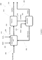
- FIG. 1 there is shown a method for the recovery of metals 10 in accordance with an embodiment of the present invention.
- a feed stream 12 is subjected to a pre-treatment process 14 to render the feed stream suitable for further processing.
- the resulting feed stream 16 is then passed to a leaching circuit 200 where it is contacted with sulfuric acid 18 to solubilise metal species. Undissolved solids 20 are removed from the leach solution to provide a pregnant leach solution 22.
- the pregnant leach solution 22 is directed to a copper solvent extraction circuit 300 where it is contacted with a copper extractant 26. Copper is loaded onto the copper extractant and the loaded extractant 28 is separated from the pregnant leach solution 22. Copper product is subsequently recovered from the copper extractant.
- the copper depleted pregnant leach solution 30 is directed to an aluminium solvent extraction circuit 400 where it is contacted with an aluminium extractant 34. Aluminium is loaded onto the aluminium extractant and the loaded extractant 36 is separated from the pregnant leach solution 30. Aluminium product is subsequently recovered from the aluminium extractant.
- the aluminium depleted pregnant leach solution 38 is directed to a cobalt / manganese recovery circuit 500 where it is contacted with an Co-Mn extractant 42. Cobalt and manganese are loaded onto the Co-Mn extractant and the loaded extractant 44 is separated from the pregnant leach solution 38. Cobalt product and manganese product are subsequently recovered from the Co-Mn extractant.
- the cobalt / manganese depleted pregnant leach solution 48 is directed to a nickel solvent extraction circuit 800 where it is contacted with a nickel extractant 52. Nickel is loaded onto the nickel extractant and the loaded extractant 54 is separated from the pregnant leach solution 48. Nickel product is subsequently recovered from the nickel extractant.
- the resulting pregnant leach solution 56 is directed towards a lithium recovery circuit 900 where it is contact with ammonium carbonate 58 to precipitate lithium carbonate.
- Lithium carbonate product 60 is recovered from the solution.
- the resulting filtrate 62 which contains ammonia, is passed to an ammonium sulfate recovery circuit 1000 to produce an ammonium sulfate product 64.
- the feed material comprises Li-ion batteries.
- the process of the present invention is adapted to treat a range of different battery types and recover a range of value metals.
- the feed stream comprises battery cathode and anode materials which contain lithium and one or more of cobalt, copper, manganese, nickel, aluminium and iron.
- the target value metals in Li-ion batteries are contained within the cathode and anode.
- Commercial batteries typically comprise the cathode and anode contained within a casing. In some instances a plastic covering is also wrapped around the casing. As no value metals are contained within the casing and covering, it is preferred that these should be removed prior to the step of subjecting the feed stream to a sulphuric acid leach.
- the feed material is subjected to a mechanical treatment step.
- the mechanical treatment step comprises a crushing and/or shredding step. It has been found by the inventor that the mechanical treatment of spent Li-ion batteries will release the anode and cathode materials from within the casings of the Li-ion batteries.
- the feed materials are subjected to a size reduction step.
- the size reduction step comprises a grinding or milling step. The inventors have found that the reduction of the particle size is beneficial for the subsequent acid leach steps.
- the average particle size of the feed material is reduced to below 5 mm.
- the average particle size of the feed material is reduced to below 4 mm.
- the average particle size of the feed material is reduced to below 3 mm.
- the average particle size of the feed material is reduced to below 2 mm.
- the average particle size of the feed material is reduced to below 1 mm.
- the average particle size of the feed material is reduced to below 900 ⁇ m.
- the average particle size of the feed material is reduced to below 800 ⁇ m.
- the average particle size of the feed material is reduced to below 700 ⁇ m.
- the average particle size of the feed material is reduced to below 600 ⁇ m.
- the average particle size of the feed material is reduced to below 500 ⁇ m.
- the one or more pretreatment steps are conducted in an inert atmosphere.
- the shredded material is subjected to one or more beneficiation steps.
- the beneficiation step separates at least some of the non-value materials from the feed stream.
- the one or more beneficiation steps comprises an air classification step.
- the inventors have found that air classification is useful for the separating of the light plastics from the heavier metal values.
- the one or more beneficiation steps comprises a magnetic separation step.
- the inventors have found that magnetic separation is useful in separating the magnetic casing material from the anode and cathode materials.
- the size reduction step is performed prior to the beneficiation step. In an alternative embodiment, the size reduction step is performed after the beneficiation step.
- the processed feed materials are directed to a leaching circuit where it is subjected to a sulphuric acid leach to form a slurry including a pregnant leach solution of soluble metal salts and a solid residue.
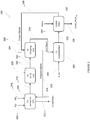
- Figure 2 shows a flowsheet of a leaching circuit 200 in accordance with one embodiment of the present invention.
- the feed material 202 is mixed with water 204 and wash filtrate 206 to form a slurry with a target solids content.
- the target solids content is dependent on the grade of the feed material and is manipulated such that sufficient dilution water is present in the discharge from the leach to maintain all soluble salts in solution.
- the slurry is passed to a series of leach reactors 208.
- Concentrated sulfuric acid 210 is added to the leach reactors 208 in sufficient excess to maintain a free acid concentration.
- At least a portion of any copper, cobalt, aluminium, iron, nickel, lithium and manganese are extracted into solution, forming a leach solution 212.
- leach reactors 108 where multiple leach reactors 108 are used, the leach reactors are arranged in series
- a gas scrubbing system (not shown) is connected to the headspace of the leach reactors 208 to remove water vapour and any other gases produced in the leach reactors 208.
- the resultant leach solution 212 is a slurry containing the pregnant leach solution and solid residue.
- the leach solution 212 is directed to a thickener 214 in order to dewater the leach solution 212 slurry.
- the overflow 216 from the thickener 214 is free of solids and is collected in a holding tank (not shown) for further processing.
- the underflow 218 from the thickener 214 is discharged, at a high solids content of approximately 65% solids by weight, to leach filter 220.
- the underflow 218 is passed to the leach filter 220 where it is dewatered further to produce a relatively dry filter cake at approximately 15% moisture content.
- Primary filtrate 222 is collected and passed to a holding tank (not shown) for further processing.
- Fresh water 224 is used in the leach filter 220 to wash the cake and maximise recovery of pregnant leach solution entrained in the filter cake.
- the wash filtrate 206 is recycled back to the head of the leach circuit 200 where it is combined with feed material 202. Filter cake is discharged from the leach filter 220 and passed to a residue stockpile for disposal.
- the feed material is mixed with water and/or wash filtrate to a target solids content.
- the target solids content is between 5% and 70% by weight. More preferably, the target solids content is between 10% and 30% by weight. Still preferably, the target solids content is about 20% by weight.
- the inventors have found that the preferred target solids content is depended on the grade of the feedstock. Generally speaking, the higher the feedstock grade, the lower the target solids content.
- the concentration of the sulphuric acid is at least 1 g/L.
- the concentration of the sulphuric acid is at least 2 g/L.
- the concentration of the sulphuric acid is at least 3 g/L.
- the concentration of the sulphuric acid is at least 4 g/L.
- the concentration of the sulphuric acid is at least 5 g/L.
- the concentration of the sulphuric acid is at least 6 g/L.
- the concentration of the sulphuric acid is at least 7 g/L.
- the concentration of the sulphuric acid is at least 8 g/L.
- the concentration of the sulphuric acid is at least 9 g/L.
- the concentration of the sulphuric acid is at least 10 g/L.
- the concentration of the sulphuric acid in the leach solution will affect the reaction/dissolution kinetics. If operated too low, the reaction will be slow to a point where it becomes impractical.
- the amount of sulphuric acid is sufficient to maintain a free acid concentration of at least 1 g/L. In one embodiment, the amount of sulphuric acid is sufficient to maintain a free acid concentration of at least 2 g/L. In one embodiment, the amount of sulphuric acid is sufficient to maintain a free acid concentration of at least 3 g/L. In one embodiment, the amount of sulphuric acid is sufficient to maintain a free acid concentration of at least 4 g/L. In one embodiment, the amount of sulphuric acid is sufficient to maintain a free acid concentration of at least 5 g/L. In one embodiment, the amount of sulphuric acid is sufficient to maintain a free acid concentration of at least 6 g/L.
- the amount of sulphuric acid is sufficient to maintain a free acid concentration of at least 7 g/L. In one embodiment, the amount of sulphuric acid is sufficient to maintain a free acid concentration of at least 8 g/L. In one embodiment, the amount of sulphuric acid is sufficient to maintain a free acid concentration of at least 9 g/L. In one embodiment, the amount of sulphuric acid is sufficient to maintain a free acid concentration of at least 10 g/L.
- the step of subjecting the feed stream to a sulphuric acid leach to form a slurry including a pregnant leach solution of soluble metal salts and a solid residue is performed at atmospheric pressure.
- Methods for leaching materials at atmospheric pressure are well known to persons skilled in the art, and include vat leaching and tank leaching.
- the step of subjecting the feed stream to a sulphuric acid leach to form a slurry including a pregnant leach solution of soluble metal salts and a solid residue takes place at elevated temperatures.
- the step of subjecting the feed stream to a sulphuric acid leach to form a slurry including a pregnant leach solution of soluble metal salts and a solid residue is conducted at a temperature of at least 40 °C.
- the step of subjecting the feed stream to a sulphuric acid leach to form a slurry including a pregnant leach solution of soluble metal salts and a solid residue is conducted at a temperature of at least 45 °C.
- the step of subjecting the feed stream to a sulphuric acid leach to form a slurry including a pregnant leach solution of soluble metal salts and a solid residue is conducted at a temperature of at least 50 °C. In one embodiment, the step of subjecting the feed stream to a sulphuric acid leach to form a slurry including a pregnant leach solution of soluble metal salts and a solid residue is conducted at a temperature of at least 55 °C. In one embodiment, the step of subjecting the feed stream to a sulphuric acid leach to form a slurry including a pregnant leach solution of soluble metal salts and a solid residue is conducted at a temperature of at least 60 °C.
- the step of subjecting the feed stream to a sulphuric acid leach to form a slurry including a pregnant leach solution of soluble metal salts and a solid residue is conducted at a temperature of at least 65 °C. In one embodiment, the step of subjecting the feed stream to a sulphuric acid leach to form a slurry including a pregnant leach solution of soluble metal salts and a solid residue is conducted at a temperature of at least 70 °C. In one embodiment, the step of subjecting the feed stream to a sulphuric acid leach to form a slurry including a pregnant leach solution of soluble metal salts and a solid residue is conducted at a temperature of at least 75 °C.
- the step of subjecting the feed stream to a sulphuric acid leach to form a slurry including a pregnant leach solution of soluble metal salts and a solid residue is conducted at a temperature of at least 80 °C. In one embodiment, the step of subjecting the feed stream to a sulphuric acid leach to form a slurry including a pregnant leach solution of soluble metal salts and a solid residue is conducted at a temperature of at least 85 °C. In one embodiment, the step of subjecting the feed stream to a sulphuric acid leach to form a slurry including a pregnant leach solution of soluble metal salts and a solid residue is conducted at a temperature of at least 90 °C.
- the leach reactors are preferably heated with steam.
- the step of the step of subjecting the feed stream to a sulphuric acid leach to form a slurry including a pregnant leach solution of soluble metal salts and a solid residue more preferably comprises: subjecting the feed stream to a sulphuric acid leach in the presence of an oxidising agent to form a slurry including a pregnant leach solution of soluble metal salts and a solid residue
- the oxidisation agent is hydrogen peroxide.
- the pregnant leach solution is passed to one or more separate solvent extraction steps to recover value metals.
- extract will be understood to refer to an organic compound dissolved in an organic solvent.
- the organic compound typically has an available proton which can be exchanged with a metal ion from the aqueous solution.
- loaded extractant and variations such as “loaded organic”, will be understood to refer to an extractant that has been enriched with metal ions that have transferred from the aqueous solution to the extractant.
- washing will be understood to refer to a purification step of a loaded extractant in which at least some undesired elements are removed.
- stripping will be understood to refer to a step transferring a metal of interest from the loaded extractant to an aqueous phase by addition of stripping solution, typically in the form of a diluted or concentrated acid or basic solution.
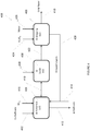
- FIG. 3 shows a flowsheet of a copper solvent extraction circuit 300 in accordance with one embodiment of the present invention.
- Pregnant leach solution 302 from the leach circuit 200 is directed to the copper solvent extraction circuit 300.
- the copper solvent extraction circuit 300 comprises an extraction stage 304, a scrubbing stage 306 and a stripping stage 308 to selectively recover copper from the pregnant leach solution 302 into a copper strip liquor 310.
- the Cu-free raffinate 312 is directed to a holding tank for further processing.
- the pregnant leach solution 302 Prior to being directed to the extraction stages 304, the pregnant leach solution 302 is pumped through a counter-current heat exchanger (not shown) to reduce the temperature of the pregnant leach solution 302.
- the cooled pregnant leach solution 302 is directed to the extraction stage 304.
- the extraction stage comprises one or more solvent extraction mixer settlers. More preferably, the extraction stage comprises two or more solvent extraction mixer settlers. Still preferably, the extraction stage comprises three or more solvent extraction mixer settlers.
- the extraction phase comprises two or more solvent extraction mixer settlers
- the two or more solvent extraction mixer settlers are arranged in series.
- the extraction stage comprises two or more solvent extraction mixer settlers arranged in series
- the mixer settlers are arranged for counter-current operation.
- the extraction stage 304 comprises three solvent extraction mixer settlers arranged in series. It is envisaged by the inventors that one or more mixer settlers may be used.
- the pregnant leach solution 302 is directed to the first mixer settler where it is contacted with a copper extractant 314 to selectively extract copper from the pregnant leach solution 302.
- the copper extractant is an organic extractant. More preferably, the copper extractant is an oxime. Still preferably the copper extractant is LIX986.
- the pregnant leach solution 302 and the copper extractant 314 are contacted in a counter-current arrangement to maximize extraction efficiency.
- Copper is selectively recovered from the pregnant leach solution 302 and the Cu-free raffinate 312 is directed to a holding tank for further processing.
- the loaded extractant 318 is directed to a scrubbing stage 306.
- the copper loaded extractant 318 is contacted with a portion of a scrub solution 320 that contains copper ions.
- the copper in the scrub solution 320 preferentially loads onto the loaded extractant 318 and displaces any impurity elements loaded onto the loaded extractant 318 in the extraction stage 304.
- the scrubbing stage comprises one or more mixer settlers.
- the scrubbing stage 306 comprises a single mixer-settler.
- the aqueous phase from the scrubbing stage 306 is directed back to the first extraction mixer-settler.
- Loaded extractant 322 from the scrubbing stage 306 advances to a stripping stage 308.
- the loaded extractant 322 is contacted with an acidic strip solution 324 to displace the majority of copper ions on the organic (in a reversal of the extraction reaction detailed in Equation 1) into the aqueous phase, producing the copper strip liquor 310.
- the stripping stage comprises one or more mixer settlers.
- the stripping stage comprises two or more mixer settlers.
- the stripping stage comprises two or more mixer settlers
- the two or more mixer settlers are arranged in series.
- the organic phase 326 exiting the stripping stage 308 is recycled to the extraction stage 304 where it again loads with copper. In this way the organic phase 326 is kept in a closed circuit within the copper solvent extraction circuit 300.
- a portion of the copper strip liquor is recycled for use as the scrub solution in the scrubbing stage 306.
- the copper strip liquor 310 from the stripping stage 306 is directed to a copper crystallization stage 328.
- the copper strip liquor 310 is contacted with sulphuric acid 330 to force the crystallisation of copper sulfate penthydrate (CuSO 4 .5H 2 O) as a solid in a salting crystallisation process.
- the copper crystallization stage 328 produces a slurry 332 of copper sulfate penthydrate and in a sulphuric liquor.
- the copper crystallization stage comprises a crystallisation unit.
- the crystallisation step is performed in a jacketed reaction vessel or scraped surface crystallizer.
- the slurry 332 from the copper crystallization stage 328 is passed to a filtration stage 334.
- a filtration stage 334 copper sulfate solids 336 are separated from acidic liquor 338.
- Water 340 is used in the filtration stage 334 to wash the filter cake and maximise removal of entrained acidic liquor 338 in the filter cake.
- the filtration stage comprises a solid liquid separation device. More preferably, the solid liquid separation device is a plate and frame filter.
- the acidic liquor is 338 is recycled back to the stripping stage 306. A portion of the copper filtrate is recycled for use in the scrubbing stage 306.
- the pregnant leach solution is cooled prior to being directed to the extraction stage. In one embodiment, the pregnant leach solution is cooled to below 65 °C. In one embodiment, the pregnant leach solution is cooled to below 60 °C. In one embodiment, the pregnant leach solution is cooled to below 55 °C. In one embodiment, the pregnant leach solution is cooled to below 50 °C. In one embodiment, the pregnant leach solution is cooled to below 45 °C. In one embodiment, the pregnant leach solution is cooled to below 40 °C. In one embodiment, the pregnant leach solution is cooled to below 35 °C. In one embodiment, the pregnant leach solution is cooled to below 30 °C. Preferably, the pregnant leach solution is cooled to at least below 50 °C. The maximum temperature is determined by the flash point, with it being practicle to operate at least 10 °C below this temperature
- the copper extractant is diluted to a target concentration with a diluent.
- the target concentration is between 20% and 40% on a volume basis. More preferably, the target concentration is about 30% on a volume basis.
- the dilution of the copper extractant is used to control viscosity.
- the diluent is Shellsol2046.
- the ratio of organic to aqueous in the extraction stage is 2.15:1.
- the ratio of organic to aqueous in the extraction stage is dependent on the copper tenor in the pregnant leach solution as well as the loading of copper on the organic.
- One method for calculation of equilibrium concentration of extractant is using the material balance, i.e. it is equal to the difference between total (analytical) concentration of extractant and the sum of all solvated species in the solvent phase.
- the target pH of the pregnant leach solution in the extraction stage is between 1 and 3. More preferably, the target pH of the pregnant leach solution in the extraction stage is 2.
- the ratio of the copper loaded extractant to the scrub solution is between 20:1 and 100:1 (organic:aqueous) on a volume basis.
- the ratio is between 25:1 and 50:1 (organic:aqueous) on a volume basis. More preferably, the ratio is about 35:1 (organic:aqueous) on a volume basis.
- the acidic strip solution 324 comprises sulphuric acid.
- the sulfuric acid concentration of the strip solution is at least 100 g/L. More preferably, the sulfuric acid concentration of the strip solution is at least 110 g/L. More preferably, the sulfuric acid concentration of the strip solution is at least 120 g/L. More preferably, the sulfuric acid concentration of the strip solution is at least 130 g/L. More preferably, the sulfuric acid concentration of the strip solution is at least 140 g/L. More preferably, the sulfuric acid concentration of the strip solution is at least 150 g/L.
- the sulphuric acid concentration of the slurry exiting the crystallisation stage is between 150 and 350 g/L.
- the sulphuric acid concentration of the slurry exiting the crystallisation stage is between 160 and 300 g/L.
- the sulphuric acid concentration of the slurry exiting the crystallisation stage is between 170 and 275 g/L.
- the sulphuric acid concentration of the slurry exiting the crystallisation stage is between 180 and 260 g/L.
- the sulphuric acid concentration of the slurry exiting the crystallisation stage is between 190 and 250 g/L.
- the sulphuric acid concentration of the slurry exiting the crystallisation stage is between 200 and 340 g/L.
- the sulphuric acid concentration of the slurry exiting the crystallisation stage is about 220 g/L.
- the temperature of the crystallisation step is controlled.
- the temperature of the crystallisation step is between 10 °C and 50 °C.
- the temperature of the crystallisation step is between 20 °C and 40 °C.
- the temperature of the crystallisation step is between 25 °C and 30 °C.
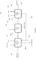
- FIG. 4 shows a flowsheet of an aluminium solvent extraction circuit 400 in accordance with one embodiment of the present invention.
- Pregnant leach solution 402 from the copper solvent extraction circuit is directed to the aluminium solvent extraction circuit 400.
- the aluminium solvent extraction circuit 400 comprises an extraction stage 404, a scrubbing stage 406 and a stripping stage 408 to selectively recover aluminium from the pregnant leach solution 402 into an aluminium strip liquor 410.
- the Al-free raffinate 412 is directed to a holding tank for further processing.
- the extraction stage comprises one or more solvent extraction mixer settlers. More preferably, the extraction stage comprises two or more solvent extraction mixer settlers. Still preferably, the extraction stage comprises three or more solvent extraction mixer settlers.
- the extraction phase comprises two or more solvent extraction mixer settlers
- the two or more solvent extraction mixer settlers are arranged in series.
- the extraction stage comprises two or more solvent extraction mixer settlers arranged in series
- the mixer settlers are arranged for counter-current operation.
- the extraction stage 404 comprises three solvent extraction mixer settlers arranged in series. It is envisaged by the inventors that one or more mixer settlers may be used.
- the pregnant leach solution 402 is directed to the first mixer settler where it is contacted with an aluminium extractant 414 to selectively extract aluminium from the pregnant leach solution 402. Iron and any remaining copper ion will also be extracted aluminium from the pregnant leach solution 402.
- the aluminium extractant is an organic extractant. More preferably, the aluminium extractant is a phosphinic acid type organic extractant. Still preferably the copper extractant is Cyanex272.
- the pregnant leach solution 402 and the aluminium extractant 414 are contacted in a counter-current arrangement to maximize extraction efficiency.
- Ammonia solution 416 is dosed to each of the mixer-settlers to maintain a target pH by neutralizing sulfuric acid via the reaction presented in Equation 2.
- Aluminium, iron and copper ions are selectively recovered from the pregnant leach solution 402 and the Al-free raffinate 412 is directed to a holding tank for further processing.
- the loaded extractant 418 is directed to a scrubbing stage 406.
- the aluminium loaded extractant 418 is contacted with a portion of a scrub solution 420 that contains aluminium ions.
- the aluminium ions in the scrub solution 420 preferentially loads onto the loaded extractant 418 and displaces any impurity elements loaded onto the loaded extractant 418 in the extraction stage 404.
- the scrubbing stage comprises one or more mixer settlers.
- the scrubbing stage 406 comprises a single mixer-settler.
- the aqueous phase from the scrubbing stage 406 is directed back to the first extraction mixer-settler.
- Loaded extractant 422 from the scrubbing stage 406 advances to a stripping stage 408.
- the loaded extractant 422 is contacted with an acidic strip solution 424.
- the acidic strip solution results in the displacement of the majority of ions on the organic (in a reversal of the extraction reaction detailed in Equation 3) into the aqueous phase, producing the aluminium strip liquor 410.
- Sufficient water 426 is added in the stripping stage 406 to prevent the crystallisation of salts in the aluminium strip liquor 410.
- the aluminium strip liquor 410 is directed to aluminium product storage. A portion of the aluminium strip liquor 410 is recycled for use as the scrub solution in the scrubbing stage.
- the stripping stage 408 comprises one or more mixer settlers.
- the stripping stage 408 comprises two or more mixer settlers.
- the stripping stage 408 comprises two or more mixer settlers
- the two or more mixer settlers are arranged in series.
- the organic phase 428 exiting the stripping stage 408 is recycled to the extraction stage 404 where it again loads with aluminium. In this way, the organic phase 428 is kept in a closed circuit within the aluminium solvent extraction circuit 400.
- the aluminium extractant is diluted to a target concentration with a diluent.
- the target concentration is between 20% and 40% on a volume basis. More preferably, the target concentration is about 30% on a volume basis.
- the aluminium extractant is diluted with a diluent
- the diluent is Shellsol2046.
- the ratio of organic to aqueous in the extraction stage is 1.85:1.
- the ratio of organic to aqueous in the extraction stage is dependent on the aluminium tenor in the pregnant leach solution as well as the loading of aluminium on the organic.
- One method for calculation of equilibrium concentration of extractant is using the material balance, i.e. it is equal to the difference between total (analytical) concentration of extractant and the sum of all solvated species in the solvent phase.
- the target pH of the pregnant leach solution in the extraction stage is between 2 and 3.5. More preferably, the target pH of the pregnant leach solution in the extraction stage is 3.3
- the ratio of the aluminium loaded extractant to the scrub solution is between 20:1 and 100:1 (organic:aqueous) on a volume basis.
- the ratio is between 30:1 and 70:1 (organic:aqueous) on a volume basis. More preferably, the ratio is about 50:1 (organic:aqueous) on a volume basis.
- the loaded extractant is contacted with sufficient acidic strip solution to achieve a target pH in the aluminium strip liquor.
- the target pH is less than 2. More preferably, the target pH is less than 1.5. More preferably, the target pH is less than 1. The inventors have found that if the pH is above 2 there is insufficient acid concentration to strip the metal from the extractant.
- water is added to the stripping stage to reach a target concentration of aluminium in the aluminium strip liquor.
- the target concentration is between 50 g/L and 70 g/L.
- FIG. 5 shows a flowsheet of a cobalt / manganese recovery circuit 500 in accordance with one embodiment of the present invention.
- Pregnant leach solution 502 from the aluminium solvent extraction circuit 400 is directed to the cobalt / manganese recovery circuit 500.
- the cobalt / manganese recovery circuit 500 comprises a Co-Mn solvent extraction circuit 504 to selectively recover cobalt / manganese from the pregnant leach solution 502.
- the Co-Mn-free raffinate 506 is directed to a holding tank for further processing.
- a resulting Co-Mn stream 507 is directed for further processing.
- the cobalt / manganese recovery circuit 500 further comprises a manganese solvent extraction circuit 508 to separate cobalt and manganese.
- a resulting cobalt containing stream 510 is directed to a cobalt crystallisation stage 512 to recover a cobalt product 514.
- a resulting manganese containing stream 516 is directed to a manganese crystallisation stage 518 to recover a manganese product 520.
- the Co-Mn solvent extraction circuit 504 comprises an extraction stage 602, a scrubbing stage 604 and a stripping stage 606 to selectively recover cobalt / manganese from the pregnant leach solution 502 into a Co-Mn strip liquor 608.
- the Co-Mn-free raffinate 506 is directed to a holding tank for further processing.
- the extraction stage comprises one or more solvent extraction mixer settlers. More preferably, the extraction stage comprises two or more solvent extraction mixer settlers. Still preferably, the extraction stage comprises three or more solvent extraction mixer settlers.
- the extraction phase comprises two or more solvent extraction mixer settlers
- the two or more solvent extraction mixer settlers are arranged in series.
- the extraction stage comprises two or more solvent extraction mixer settlers arranged in series
- the mixer settlers are arranged for counter-current operation.
- the extraction stage 602 comprise four solvent extraction mixer settlers arranged in series. It is envisaged by the inventors that one or more mixer settlers may be used.
- the pregnant leach solution 502 is directed to the first mixer settler where it is contacted with a Co-Mn extractant 610 to selectively extract cobalt / manganese from the pregnant leach solution 502.
- the Co-Mn extractant is phosphonic acid type organic extractant. Still preferably, the Co-Mn extractant is Cyanex272.
- the pregnant leach solution 502 and the Co-Mn extractant 610 are contacted in a counter-current arrangement to maximize extraction efficiency.
- Ammonia solution 612 is dosed to each of the mixer-settlers to maintain a target pH by neutralizing sulfuric acid via the reaction presented in Equation 2.
- Cobalt and manganese is selectively recovered from the pregnant leach solution 502 and the Co-Mn-free raffinate 506 is directed to a holding tank for further processing.
- the loaded extractant 614 is directed to a scrubbing stage 604.
- the loaded extractant 614 is contacted with a portion of a scrub solution 616.
- the cobalt / manganese in the scrub solution 616 preferentially loads onto the loaded extractant 614 and displaces any impurity elements loaded onto the loaded extractant 614 in the extraction stage 602.
- the scrubbing stage comprises one or more mixer settlers.
- the scrubbing stage 604 comprises a single mixer-settler.
- the aqueous phase from the scrubbing stage 604 is directed back to the first extraction mixer-settler.
- Loaded extractant 618 from the scrubbing stage 604 advances to a stripping stage 606.
- the loaded extractant 618 is contacted with an acidic strip solution 620 to displace the majority of cobalt / manganese ions on the organic (in a reversal of the extraction reaction detailed in Equation 1) into the aqueous phase, producing the Co-Mn strip liquor 608.
- Sufficient water 622 is added in the stripping stage 606 to prevent the crystallisation of salts in the Co-Mn strip liquor 608.
- the Co-Mn strip liquor 608 is directed to the manganese solvent extraction circuit 508.
- the stripping stage comprises one or more mixer settlers.
- the stripping stage comprises two or more mixer settlers.
- the stripping stage comprises two or more mixer settlers
- the two or more mixer settlers are arranged in series.
- the organic phase 624 exiting the stripping stage 606 is recycled to the extraction stage 602 where it again loads with cobalt / manganese. In this way the organic phase 624 is kept in a closed circuit within the cobalt / manganese solvent extraction circuit 504.
- the Co-Mn strip liquor 608 is directed to the manganese solvent extraction circuit 508.
- the Co-Mn extractant is diluted to a target concentration with a diluent.
- the target concentration is between 15% and 35% on a volume basis. More preferably, the target concentration is about 30% on a volume basis.
- the dilution of the Co-Mn extractant is used to control viscosity.
- the diluent is Shellsol2046.
- the ratio of organic to aqueous in the extraction stage is 3.1:1.
- the ratio of organic to aqueous in the extraction stage is dependent on the cobalt / manganese tenor in the pregnant leach solution as well as the loading of cobalt / manganese on the organic.
- One method for calculation of equilibrium concentration of extractant is using the material balance, i.e. it is equal to the difference between total (analytical) concentration of extractant and the sum of all solvated species in the solvent phase.
- the target pH of the pregnant leach solution in the extraction stage is between 4.2 and 5. More preferably, the target pH of the pregnant leach solution in the extraction stage is 4.8.
- the ratio of the Co-Mn loaded extractant to the scrub solution is between 20:1 and 100:1 (organic:aqueous) on a volume basis.
- the ratio is between 30:1 and 70:1 (organic:aqueous) on a volume basis. More preferably, the ratio is about 50:1 (organic:aqueous) on a volume basis.
- the acidic strip solution comprises sulphuric acid.
- the loaded extractant is contacted with sufficient acidic strip solution to achieve a target pH in the Co-Mn strip liquor.
- the target pH is below 3.
- water is added to the stripping stage to reach a target concentration of cobalt in the Co-Mn strip liquor.
- target concentration is between 80 g/L and 140 g/L.
- the manganese extraction circuit 508 comprises a preload stage 720, an extraction stage 722, a scrubbing stage 724 and a stripping stage 726 to selectively recover manganese from the Co-Mn strip liquor 608 into a manganese strip liquor 730 and a cobalt raffinate 732.
- the Co-Mn strip liquor 608 is directed to the extraction stage 722 where it is contacted with a preload organic 734 from the preload stage 720. It is envisaged that the preload organic 734 may be supplemented or replaced with a fresh stream of manganese extractant (not shown).
- stripped organic 736 from the manganese stripping stage 726 (described below) is contacted with the cobalt filtrate 740 from the cobalt filter 742 (described below).
- the manganese extraction circuit 508 may operate without the preload stage 720. In such an embodiment fresh manganese extractant would be introduced into the extraction stage 722.
- the use of the preload stage 720 has been found to prevent the need for ammonia to be introduced into the manganese solvent extraction circuit.
- the extraction stage comprises one or more solvent extraction mixer settlers. More preferably, the extraction stage comprises two or more solvent extraction mixer settlers. Still preferably, the extraction stage comprises three or more solvent extraction mixer settlers.
- the extraction phase comprises two or more solvent extraction mixer settlers
- the two or more solvent extraction mixer settlers are arranged in series.
- the extraction stage comprises two or more solvent extraction mixer settlers arranged in series
- the mixer settlers are arranged for counter-current operation.
- the preload stage 720 comprises three mixer settlers arranged in series. It is envisaged by the inventors that one or more mixer settlers may be used.
- the cobalt filtrate 740 is directed to the first mixer settler where it is contacted with stripped organic 736 to selectively extract cobalt ions from the cobalt filtrate 740.
- the stripped organic 736 from the manganese stripping stage 726 comprises a phosphonic acid type organic extractant. Still preferably the stripped organic 736 is DHEPA.
- the cobalt filtrate 740 and the stripped organic 736 are contacted in a counter-current arrangement to maximize extraction efficiency.
- Ammonia solution 534 is dosed to each of the mixer-settlers to maintain a target pH by neutralizing sulfuric acid via the reaction presented in Equation 2.
- the flow rate of the cobalt filtrate 740 directed to the preload stage 720 is controlled to achieve a target cobalt loading on the stripped organic 736.
- the target cobalt loading is such that the moles of cobalt ions loaded are substantially equivalent to the moles of manganese ions in the Co-Mn strip liquor 608.
- a preferred ratio of Co:Mn is between 1:1 and 1.1:1.
- the target loading is dependent on the manganese tenor in the Co-Mn strip liquor 608. If insufficient cobalt is loaded then ammonia will need to be introduced to the extraction stage to extract all the manganese.
- the pre-load raffinate 510 still contains cobalt and so it can be directed to extraction stage 602 of the Co-Mn solvent extraction circuit 504.
- the preload organic 734 is directed to the extraction stage 722 where it is contacted with the Co-Mn strip liquor 608.
- the extraction stage comprises one or more solvent extraction mixer settlers. More preferably, the extraction stage comprises two or more solvent extraction mixer settlers. Still preferably, the extraction stage comprises three or more solvent extraction mixer settlers.
- the extraction phase comprises two or more solvent extraction mixer settlers
- the two or more solvent extraction mixer settlers are arranged in series.
- the mixer settlers are arranged for counter-current operation.
- the extraction stage 722 comprises three solvent extraction mixer settlers arranged in series. It is envisaged by the inventors that one or more mixer settlers may be used.
- the Co-Mn strip liquor 608 is directed to the first mixer settler where it is contacted with the preload organic 734, to selectively extract manganese from the Co-Mn strip liquor 608.
- Co-Mn strip liquor 608 and the preload organic 734 are contacted in a counter-current arrangement to maximize extraction efficiency.
- Ammonia solution 744 is dosed to each of the mixer-settlers to maintain a target pH by neutralizing sulfuric acid via the reaction presented in Equation 2.
- Manganese is selectively recovered from the Co-Mn strip liquor 608 to produce a loaded organic 746.
- the Mn-free raffinate 510 is directed to the cobalt crystallisation stage 512.
- the loaded organic 746 is directed to a scrubbing stage 724.
- the manganese organic 736 is contacted with a portion of a scrub solution 748.
- the manganese in the scrub solution 748 preferentially loads onto the loaded organic 746 and displaces any cobalt loaded onto the loaded organic 746 by the reaction given in Equation 6.
- the scrubbing stage comprises one or more mixer settlers.
- the scrubbing stage 724 comprises a single mixer-settler.
- the aqueous phase from the scrubbing stage 724 is directed back to the first extraction mixer-settler.
- Loaded extractant 750 from the scrubbing stage 724 advances to a stripping stage 726.
- the loaded extractant 750 is contacted with an acidic strip solution 752 to displace the majority of manganese ions on the organic (in a reversal of the extraction reaction detailed in Equation 4) into the aqueous phase, producing the manganese strip liquor 730.
- Sufficient water 754 is added in the stripping stage 726 to prevent the crystallisation of salts in the manganese strip liquor 730.
- the stripping stage comprises one or more mixer settlers.
- the stripping stage comprises two or more mixer settlers.
- the stripping stage comprises two or more mixer settlers
- the two or more mixer settlers are arranged in series.
- the organic phase 736 exiting the stripping stage 726 is recycled to the preload stage 720. In this way the organic phase 736 is kept in a closed circuit within the manganese solvent extraction circuit 704.
- the manganese strip liquor 730 is directed to the manganese crystallisation stage 518.
- the manganese strip liquor 730 from the stripping stage 726 is directed to a manganese crystallization stage 518.
- water is removed from the manganese strip liquor 730 to cause the crystallisation of MnSO 4 .H 2 O in a slurry 756.
- the manganese crystallization stage comprises a crystallisation unit.
- the crystallisation unit is an evaporative crystalliser.
- the slurry 756 from the manganese crystallization stage 518 is passed to a filtration stage 758.
- a filtration stage 758 manganese sulfate solids 520 are separated from filtrate.
- Water 760 is used in the filtration stage 758 to wash the filter cake and maximise recovery of manganese.
- the filtrate is recycled back to the manganese crystallization stage 518 to maximise the recovery of manganese. A portion of the filtrate may also be recycled for use in the manganese scrubbing stage 724.
- the cobalt raffinate 510 from the extraction stage 722 is directed to a cobalt crystallization stage 512.
- water is removed from the cobalt raffinate 510 to cause the crystallisation of COSO 4 .7H 2 O in a slurry 762.
- the cobalt crystallization stage 512 comprises a crystallisation unit.
- the crystallisation unit is an evaporative crystalliser.
- the slurry 762 from the cobalt crystallization stage 512 is passed to a filtration stage 742.
- cobalt sulfate solids 514 are separated from filtrate.
- Water 764 is used in the filtration stage 742 to wash the filter cake and maximise recovery of cobalt.
- the filtrate is recycled back to the cobalt crystallization stage 512 to maximise the recovery of cobalt. A portion of the filtrate is recycled for use in the preload stage 720.
- the manganese extractant is diluted to a target concentration with a diluent.
- the target concentration is between 15% and 35% on a volume basis. More preferably, the target concentration is about 30% on a volume basis.
- the dilution of the manganese extractant is used to control viscosity.
- the diluent is Shellsol2046.
- the target pH of the preload stage is between 4.5 and 12. More preferably, the target pH of the preload stage is 4.8.
- the cobalt loading in the preloaded organic is at least 10 g/L.
- the cobalt loading in the preloaded organic is at least 11 g/L.
- the cobalt loading in the preloaded organic is at least 12 g/L.
- the cobalt loading in the preloaded organic is at least 13 g/L.
- the cobalt loading in the preloaded organic is at least 13.5 g/L.
- the cobalt loading in the preloaded organic is at about 13.8 g/L.
- the preloaded organic is diluted to a target concentration with a diluent.
- the target concentration is between 15% and 35% on a volume basis. More preferably, the target concentration is about 30% on a volume basis.
- the dilution of the manganese extractant is used to control viscosity.
- the diluent is Shellsol2046.
- the ratio of organic to aqueous in the extraction stage is 1.65:1.
- the ratio of organic to aqueous in the extraction stage is dependent on the manganese tenor in the pregnant leach solution as well as the loading of manganese on the organic.
- One method for calculation of equilibrium concentration of extractant is using the material balance, i.e. it is equal to the difference between total (analytical) concentration of extractant and the sum of all solvated species in the solvent phase.
- the ratio of the manganese loaded extractant to the scrub solution is between 20:1 and 100:1 (organic:aqueous) on a volume basis.
- the ratio is between 30:1 and 70:1 (organic:aqueous) on a volume basis. More preferably, the ratio is about 50:1 (organic:aqueous) on a volume basis.
- the acidic strip solution comprises sulphuric acid.
- the loaded extractant is contacted with sufficient acidic strip solution to achieve a target pH in the manganese strip liquor.
- the target pH is below 3.
- water is added to the stripping stage to reach a target concentration of manganese in the manganese strip liquor.
- target concentration is between 100 g/L and 220 g/L.
- FIG. 8 shows a flowsheet of a nickel solvent extraction circuit 800 in accordance with one embodiment of the present invention.
- Pregnant leach solution 802 from the cobalt / manganese solvent extraction circuit is directed to the nickel solvent extraction circuit 800.
- the nickel solvent extraction circuit 800 comprises an extraction stage 804, a scrubbing stage 806 and a stripping stage 808 to selectively recover nickel from the pregnant leach solution 802 into a nickel strip liquor 810.
- the Ni-free raffinate 812 now largely free of other metals, is directed to a holding tank for further processing.
- the extraction stage comprises one or more solvent extraction mixer settlers. More preferably, the extraction stage comprises two or more solvent extraction mixer settlers arranged in series.
- the extraction stage comprises two or more solvent extraction mixer settlers arranged in series
- the mixer settlers are arranged for counter-current operation.
- the extraction stage 804 comprises three solvent extraction mixer settlers arranged in series. It is envisaged by the inventors that one or more mixer settlers may be used.
- the pregnant leach solution 802 is directed to the first mixer settler where it is contacted with a nickel extractant 814 to selectively extract nickel from the pregnant leach solution 802.
- the nickel extractant is an organic extractant. More preferably, the nickel extractant is an oximes. Still preferably the nickel extractant is LIX986.
- the pregnant leach solution 802 and the nickel extractant 814 are contacted in a counter-current arrangement to maximize extraction efficiency.
- Ammonia solution 816 is dosed to each of the mixer-settlers to maintain a target pH by neutralizing sulfuric acid via the reaction presented in Equation 2.
- Nickel is selectively recovered from the pregnant leach solution 802 and the Ni-free raffinate 812 is directed to a holding tank for further processing.
- the loaded extractant 818 is directed to a scrubbing stage 806.
- the nickel loaded extractant 818 is contacted with a portion of a scrub solution 820 containing nickel ions.
- the nickel ions in the scrub solution 820 preferentially loads onto the loaded extractant 818 and displaces any impurity elements loaded onto the loaded extractant 318 in the extraction stage 804.
- the scrubbing stage comprises one or more mixer settlers.
- the scrubbing stage comprises a single mixer-settler.
- the aqueous phase from the scrubbing stage 806 is directed back to the first extraction mixer-settler.
- Loaded extractant 822 from the scrubbing stage 806 advances to a stripping stage 808.
- the loaded extractant 820 is contacted with an acidic strip solution 824 to displace the majority of nickel ions on the organic (in a reversal of the extraction reaction detailed in Equation 7) into the aqueous phase, producing the nickel strip liquor 810.
- Sufficient water 825 is added in the stripping stage 808 to prevent the crystallisation of salts in the nickel strip liquor 810.
- the stripping stage 808 comprises one or more mixer settlers.
- the stripping stage 808 comprises two or more mixer settlers.
- the stripping stage 808 comprises two or more mixer settlers
- the two or more mixer settlers are arranged in series.
- the organic phase 826 exiting the stripping stage 808 is recycled to the extraction stage 804 where it again loads with nickel. In this way the organic phase 826 is kept in a closed circuit within the nickel solvent extraction circuit 800.
- the nickel strip liquor 810 from the stripping stage 808 is directed to a nickel crystallization stage 828.
- the nickel crystallization stage 828 comprises a crystallisation unit.
- the crystallisation unit is an evaporative crystalliser.
- the slurry 830 from the nickel crystallization stage 828 is passed to a filtration stage 832.
- nickel sulfate solids 834 are separated from filtrate.
- Water 840 is used in the filtration stage 832 to wash the filter cake and maximise recovery of nickel.
- the filtrate is recycled back to the nickel crystallization stage 828 to maximise the recovery of nickel.
- a portion of the 836 is recycled for use in the scrubbing stage 806.
- Nickel sulfate solids 834 are transported a nickel sulfate product stockpile.
- the nickel extractant is diluted to a target concentration with a diluent.
- the target concentration is between 15% and 35% on a volume basis. More preferably, the target concentration is about 30% on a volume basis.
- the dilution of the nickel extractant is used to control viscosity.
- the diluent is Shellsol2046.
- the ratio of organic to aqueous in the extraction stage is 3.55:1.
- the ratio of organic to aqueous in the extraction stage is dependent on the nickel tenor in the pregnant leach solution as well as the loading of nickel on the organic.
- One method for calculation of equilibrium concentration of extractant is using the material balance, i.e. it is equal to the difference between total (analytical) concentration of extractant and the sum of all solvated species in the solvent phase.
- the target pH of the pregnant leach solution in the extraction stage is at least 6.4. More preferably, the target pH of the pregnant leach solution in the extraction stage is between 6.4 and 6.9 .
- the ratio of the nickel loaded extractant to to the scrub solution is between 20:1 and 100:1 (organic:aqueous) on a volume basis.
- the ratio is between 30:1 and 70:1 (organic:aqueous) on a volume basis. More preferably, the ratio is about 50:1 (organic:aqueous) on a volume basis.
- the acidic strip solution comprises sulphuric acid.
- the loaded extractant is contacted with sufficient acidic strip solution to achieve a target pH in the manganese strip liquor.
- the target pH is below 4.
- water is added to the stripping stage to reach a target concentration of nickel in the manganese strip liquor.
- target concentration is 50 g/L and 120 g/L.
- FIG. 9 shows a flowsheet of a lithium solvent extraction circuit 900 in accordance with one embodiment of the present invention.
- Pregnant leach solution 902 from the nickel solvent extraction circuit is directed to the lithium solvent extraction circuit 900.
- the lithium solvent extraction circuit 900 comprises an evaporation stage 904, a precipitation stage 906 and a filtration stage 908 to selectively recover lithium from the pregnant leach solution 902 into a lithium solid 910.
- the Li-free filtrate 912 now largely free of metals, is directed to a holding tank for further processing.
- Pregnant leach solution 902 is directed to an evaporation stage 904 where water is removed from the pregnant leach solution 902 to produce a concentrated lithium liquor 914. Water removal is targeted to maximize the concentration of lithium in concentrated lithium liquor 914 to just below the solubility limit of salts in the concentrated lithium liquor 914.
- the evaporation stage 904 comprises an evaporator unit.
- the evaporator unit is a falling film type evaporator.
- Energy is input through the use of steam in an indirect heat exchanger. Evaporation is conducted at high temperature and moderate vacuum to assist in the efficient removal of water.
- Concentrated lithium liquor 914 is directed to the precipitation stage 906 where it is contacted with ammonium carbonate 916 to precipitate lithium carbonate in a lithium carbonate slurry 918.
- the precipitation lithium carbonate occurs in accordance with the reaction in Equation 8.
- Li 2 SO 4 aq + NH 4 2 CO 3 aq Li 2 CO 3 s + NH 4 2 SO 4 aq
- the precipitation stage comprises one or more reaction vessels.
- the lithium carbonate slurry 918 is maintained at an elevated temperature. It is understood by the inventors that by conducting the precipitation step at elevated temperatures, the precipitation efficiency is maximized by taking advantage of the inverse temperature-solubility profile of lithium carbonate.
- the lithium carbonate slurry 918 is passed to the filtration stage 908 to separate lithium carbonate solid 910 from the lithium carbonate slurry 918.
- the filtration stage comprises a solid liquid separation device. More preferably, the solid liquid separation device is a centrifuge.
- Fresh water 920 is used in the filtration stage 908 to wash the cake and maximise removal of entrained liquor in the filter cake.
- the Li-free filtrate 912, comprising ammonia is directed to a holding tank for further processing.
- the Li-free filtrate 912 now largely free of metals, is directed to a holding tank for further processing.
- the concentration of lithium in the concentrated lithium liquor is targeted at 300 g/L Li 2 SO 4 .
- the lithium carbonate slurry is maintained at a temperature of at least 90°C
- FIG. 10 shows a flowsheet of a ammonium sulfate recovery circuit 1000 in accordance with one embodiment of the present invention. Filtrate 902 from the lithium recovery circuit is directed to the ammonium sulfate recovery circuit 1000.
- the ammonium sulfate recovery circuit 1000 comprises a crystallisation stage 1004 and a filtration stage 1006 to selectively recover ammonium sulfate from the pregnant leach solution 902 into a ammonium sulfate solid 1008.
- the filtrate 902 is directed to the crystallisation stage 1004.
- water is removed from the filtrate 902 to cause the crystallisation of ammonia as ammonium sulfate (NH 4 ) 2 SO 4 in a slurry 1012. Water removal is targeted to maximize recovery of ammonium sulfate as a solid. Any compounds still remaining in the lithium filtrate (i.e NiSO 4 , Li 2 CO 3 etc) will co-crystallise as impurities.
- the ammonium sulfate crystallization stage 1004 comprises a crystallisation unit.
- the crystallisation unit is an evaporative crystalliser.
- the evaporative crystalliser is a forced circulation type evaporative crystalliser.
- the slurry 1012 from the crystallisation stage 1004 is passed to a filtration stage 1006.
- the precipitated ammonium sulfate solids are separated from filtrate 1014.
- Water 1016 is used in the filtration stage 1006 to wash the filter cake and maximise recovery of ammonium sulfate.
- the filtrate 1014 is recycled back to the crystallisation stage 1004 to maximise the recovery of ammonium sulfate.
- the recovered ammonium sulfate solid 1008 is discharged from the filter press and passed to an ammonium sulfate product stockpile.
- Table 1 Battery Assay SAMPLE Mass (kg) Yield (%) Total 7.468 100.00% Fraction Plastic Waste Fraction 0.788 10.56% Battery Cell Fraction 6.459 86.48% Circuitry Fraction 0.221 2.96%
- the battery sample was subjected to a H 2 SO 4 leach with SO 2 gas sparged through the leach vessel.
- the leach parameters are shown in Table 3.
- Table 3 Leach Parameters Size: 10mm P100 Start Mass: 57.1 g Pulp Density: 20.0 % (w/w) H2SO4 Conc: 30 % (w/w) Leach Time: 2.0 hours Leach Temp: 100 °C Sparge rate (SO2) 0.02 L/min
- Table 4 Leach Results Solid Mass Li Co Fe Al Ni Cu g ppm ppm ppm ppm ppm ppm Leach Residue 74.74 7269 147122 635 10795 5210 70767 Solution Volume Li Co Fe Al Ni Cu mL mg/L mg/L mg/L mg/L mg/L mg/L mg/L mg/L Leach Liquor 24.52957 19460 27730 30 27570 2760 18080 Wash 249.1459 3382 12098 24 4732 585 3793 Calc Head. 57.14 32608.36 257092.6 948.1149 46588.33 10550.36 116864.4 Table 5: Leach Distribution Solid Mass Li Co Fe Al Ni Cu g dist. dist.
- Table 10 Leach Results Solid Mass Li Co Fe Al Ni Cu g ppm ppm ppm ppm ppm ppm Leach Residue 17.3 4037 65674 1045 12605 1271 66480 Solution Volume Li Co Fe Al Ni Cu mL mg/L mg/L mg/L mg/L mg/L mg/L mg/L mg/L Leach Liquor 253.0 5704 42328 84 8381 1362 16790 Wash 340.2 427 3670 6 652 109.00 1616.00 Calc Head. (ppm ) 51.55 32163 253970 802 49660 7829 115366.24 Table 11: Leach Distribution Solid Mass Li Co Fe Al Ni Cu g dist. dist. dist.
- the invention described herein may include one or more range of values (eg. size, displacement and field strength etc).
- a range of values will be understood to include all values within the range, including the values defining the range, and values adjacent to the range which lead to the same or substantially the same outcome as the values immediately adjacent to that value which defines the boundary to the range.
Abstract
Description
- The present invention relates to a method for the recovery of metals from feed materials containing such metals. More specifically, the present invention relates to the recovery of various metals contained in spent lithium-based (Li-ion) batteries.
- The following discussion of the background art is intended to facilitate an understanding of the present invention only. The discussion is not an acknowledgement or admission that any of the material referred to is or was part of the common general knowledge as at the priority date of the application.
- The volume of rechargeable Li-ion batteries used worldwide has been growing rapidly in recent years and is set for further expansion with the emerging markets of electric vehicles and mass electric power storage. As the demand for Li-ion batteries increases, so does the demand for the metal / metal oxide components that are used in the batteries. The rapid increase in demand for some of these metals, such as cobalt, has put pressure on the sustainable supply of such resources. This has caused the cost of such metals to rapidly increase.
- There has been little interest in developing processes for the recovery and recycling of the various components in modern batteries. This is mainly due to the relatively low volume of Li-ion batteries available for recycling and the relatively high cost of the typical pyro- and hydro-metallurgical processes by which the recovery is achieved. As the demand for Li-ion batteries continues to increase, so too does the volume of spent Li-ion batteries that are available for recycling. There is a need for low-cost, efficient recycling processes, particularly for the more complex metal/metal oxide components.
- The composition of Li-ion batteries has evolved considerably over recent times. Whilst some battery recycling processes have been developed, these have primarily been limited to the recovery of certain metals from a certain type of battery or feed source. For example, early batteries were predominantly lithium-cobalt and the focus of the recovery methods was on the recovering cobalt. As lithium demand increased, the recovery methods shifted to the recovery of both cobalt and lithium. As battery technologies further developments, the cathodes incorporated other metals, such as manganese, nickel, aluminium, iron and phosphorus. The methods used to recovery lithium and cobalt are not suited for the recovery of other metals, nor are they well suited for different battery chemistries.
- The uptake in the usage of Li-ion batteries will increase the volume of spent Li-ion batteries available for recycling. However, the supply of spent Li-ion batteries will include many different types of batteries. The suitability of recovery methods to only a single battery type presents a significant problem to the commercialisation of such processes as it will require sorting. There is a need for the development of a process for the recovery of a range of metals from a range of different Li-ion battery types.
- It is against this background that the present invention has been developed.
- The present invention seeks to overcome, or at least ameliorate, one or more of the deficiencies of the prior art mentioned above, or to provide the consumer with a useful or commercial choice.
- Throughout this specification, unless the context requires otherwise, the word "comprise" or variations such as "comprises" or "comprising", will be understood to imply the inclusion of a stated integer or group of integers but not the exclusion of any other integer or group of integers.
- In accordance with a first aspect of the present invention, there is provided a method for the recovery of metals from a feed stream containing one or more value metals and lithium, the method comprising:
- subjecting the feed stream to a sulphuric acid leach to form a slurry including a pregnant leach solution of soluble metal salts and a solid residue;
- separating the pregnant leach solution and the solid residue;
- subjecting the pregnant leach solution to one or more separate solvent extraction steps, wherein each solvent extraction step recovers one or more value metals from the pregnant leach solution, the remaining pregnant leach solution comprising lithium; and
- recovery of lithium from the pregnant leach solution.
- The method of the present invention is particularly useful for the recovery of at least a significant portion of all the value metals from spent Li-ion batteries, preferably as high purity sulphates. The process is particularly robust in that it can accommodate a variety of Li-ion battery chemistries as a single or mixed feed source. This is achieved by way of an oxidative acidic leach at atmospheric pressures followed by stage wise sequential metal recovery using solvent extraction techniques. This has been found to particularly advantageous as there is no sorting of different battery types required.
- In preferred forms of the present invention, the feed stream comprises one or more of copper, iron, aluminium, cobalt and nickel.
- In one embodiment of the present invention, the method further comprises the step of:
subjecting the feed stream to a pretreatment process,
prior to the step of subjecting the feed stream to a sulphuric acid leach. - Preferably, the pre-treatment process comprises one or more mechanical treatment steps. More preferably, the mechanical treatment steps comprises one or more of: a crushing step and a shredding step.
- Preferably, the pre-treatment process comprises one or more size reduction steps. More preferably, the one or more size reduction steps comprise a grinding step.
- In one form of the present invention, the pre-treatment process comprises one or more beneficiation steps. Preferably, the one or more beneficiation steps include one or more of an air classification step, a magnetic classification step and a floatation step.
- In one form of the present invention, the steps of:
- subjecting the feed stream to a sulphuric acid leach to form a slurry including a pregnant leach solution of soluble metal salts and a solid residue; and
- separating the pregnant leach solution and the solid residue,
- In one form of the present invention, the step of:
subjecting the feed stream to a sulphuric acid leach to form a slurry including a pregnant leach solution of soluble metal salts and a solid residue,
more specifically comprises subjecting the feed stream to a sulphuric acid leach in one or more leach reactors. Preferably, the step comprises subjecting the feed stream to a sulphuric acid leach in two or more leach reactors. More preferably, the step comprises subjecting the feed stream to a sulphuric acid leach in three or more leach reactors. More preferably, the step comprises subjecting the feed stream to a sulphuric acid leach in four or more leach reactors. More preferably, the step comprises subjecting the feed stream to a sulphuric acid leach in five or more leach reactors. - Preferably, the step of subjecting the feed stream to a sulphuric acid leach is conducted at atmospheric pressure.
- Preferably, the step of subjecting the feed stream to a sulphuric acid leach is conducted at elevated temperature.
- In one form of the present invention, each solvent extraction step comprises the contact of the pregnant leach solution with an extractant to extract one or more metals to produce a loaded extractant containing the one or more extracted metals. Preferably, each solvent extraction step further comprises the separation of the loaded extractant from the pregnant leach solution. More preferably, each solvent extraction step further comprises the recovery of the metal from the loaded extractant.
- In one form of the present invention, one of the separate solvent extraction steps is adapted to recover copper from the pregnant leach solution. Preferably, the pregnant leach solution is contacted with a copper extractant to produce a copper depleted pregnant leach solution and loaded copper extractant. More preferably, copper is recovered from the loaded copper extractant.
- In one form of the present invention, one of the separate solvent extraction steps is adapted to recover aluminium from the pregnant leach solution. Preferably, the pregnant leach solution is contacted with an aluminium extractant to produce an aluminium depleted pregnant leach solution and loaded aluminium extractant. More preferably, aluminium is recovered from the loaded aluminium extractant.
- In one form of the present invention, the contact of the pregnant leach solution with an aluminium extractant will further load iron from the pregnant leach solution onto the loaded aluminium extractant.
- In one form of the present invention, one of the separate solvent extraction steps is adapted to recover cobalt and manganese from the pregnant leach solution. Preferably, the pregnant leach solution is contacted with a Co-Mn extractant to produce a copper and manganese depleted pregnant leach solution and loaded Co-Mn extractant. More preferably, cobalt and manganese are recovered from the loaded Co-Mn extractant.
- In one form of the present invention, one of the separate solvent extraction steps is adapted to recover nickel from the pregnant leach solution. Preferably, the pregnant leach solution is contacted with a nickel extractant to produce a nickel depleted pregnant leach solution and loaded nickel extractant. More preferably, nickel is recovered from the loaded nickel extractant.
- In one form of the present invention, the separate solvent extraction steps are performed sequentially. Preferably, the separate solvent extractions step are performed in the sequence: copper, aluminium, cobalt/manganese, and nickel.
- In one form of the present invention, following the one or more separate solvent extraction steps, the pregnant leach solution comprises lithium.
- In one form of the present invention, the recovery of lithium from the pregnant leach solution more specifically comprises the precipitation of a lithium compound. More preferably, the lithium compound is subsequently recovered from the solution. In one embodiment, the lithium compound is lithium carbonate. Preferably, the pregnant leach solution is contacted with ammonium carbonate to precipitate lithium carbonate.
- In one form of the present invention, the recovery of lithium from the pregnant leach solution more specifically comprises the recovery of lithium using solvent extraction.
- In one form of the present invention, the recovery of lithium from the pregnant leach solution more specifically comprises the recovery of lithium using ion exchange.
- In one form of the present invention, the recovery of lithium from the pregnant leach solution more specifically comprises the use of an electrolysis step. Preferably, the electrolysis step produces a solution of LiOH.
- In one form of the present invention, following the step of lithium recovery, the leach solution is subjected to an ammonia recovery step. Preferably, the ammonia recovery step comprises an ammonium sulfate crystallisation step.
- Further features of the present invention are more fully described in the following description of several non-limiting embodiments thereof. This description is included solely for the purposes of exemplifying the present invention. It should not be understood as a restriction on the broad summary, disclosure or description of the invention as set out above. The description will be made with reference to the accompanying drawings in which:
-
Figure 1 is a flow sheet of the method of the present invention; -
Figure 2 is a flow sheet of leaching circuit; -
Figure 3 is flow sheet of the copper solvent extraction circuit; -
Figure 4 is flow sheet of the aluminium solvent extraction circuit; -
Figure 5 is flow sheet of the cobalt / manganese recovery circuit; -
Figure 6 is a flow sheet of the Co-Mn solvent extraction circuit; -
Figure 7 is flow sheet of the manganese solvent extraction circuit; -
Figure 8 is flow sheet of the nickel solvent extraction circuit; -
Figure 9 is flow sheet of the lithium recovery circuit; and -
Figure 10 is flow sheet of the ammonium sulfate recovery circuit. - As described above, in one aspect of the invention, there is provided a method for the recovery of metals from a feed stream containing one or more value metals and lithium, the method comprising:
- subjecting the feed stream to a sulphuric acid leach to form a slurry including a pregnant leach solution of soluble metal salts and a solid residue;
- separating the pregnant leach solution and the solid residue;
- subjecting the pregnant leach solution to one or more separate solvent extraction steps, wherein each solvent extraction step comprises the contact of the pregnant leach solution with an extractant to extract one or more metals, the separation of the loaded extractant from the pregnant leach solution and the recovery of the metal from the loaded extractant;
- recovery of lithium from the pregnant leach solution.
- In
Figure 1 , there is shown a method for the recovery ofmetals 10 in accordance with an embodiment of the present invention. In this embodiment, afeed stream 12 is subjected to apre-treatment process 14 to render the feed stream suitable for further processing. The resultingfeed stream 16 is then passed to aleaching circuit 200 where it is contacted withsulfuric acid 18 to solubilise metal species.Undissolved solids 20 are removed from the leach solution to provide apregnant leach solution 22. - The
pregnant leach solution 22 is directed to a coppersolvent extraction circuit 300 where it is contacted with acopper extractant 26. Copper is loaded onto the copper extractant and the loadedextractant 28 is separated from thepregnant leach solution 22. Copper product is subsequently recovered from the copper extractant. - The copper depleted
pregnant leach solution 30 is directed to an aluminiumsolvent extraction circuit 400 where it is contacted with analuminium extractant 34. Aluminium is loaded onto the aluminium extractant and the loadedextractant 36 is separated from thepregnant leach solution 30. Aluminium product is subsequently recovered from the aluminium extractant. - The aluminium depleted
pregnant leach solution 38 is directed to a cobalt /manganese recovery circuit 500 where it is contacted with anCo-Mn extractant 42. Cobalt and manganese are loaded onto the Co-Mn extractant and the loadedextractant 44 is separated from thepregnant leach solution 38. Cobalt product and manganese product are subsequently recovered from the Co-Mn extractant. - The cobalt / manganese depleted
pregnant leach solution 48 is directed to a nickelsolvent extraction circuit 800 where it is contacted with anickel extractant 52. Nickel is loaded onto the nickel extractant and the loadedextractant 54 is separated from thepregnant leach solution 48. Nickel product is subsequently recovered from the nickel extractant. - The resulting
pregnant leach solution 56 is directed towards alithium recovery circuit 900 where it is contact withammonium carbonate 58 to precipitate lithium carbonate.Lithium carbonate product 60 is recovered from the solution. The resultingfiltrate 62, which contains ammonia, is passed to an ammoniumsulfate recovery circuit 1000 to produce anammonium sulfate product 64. - A more detailed description of each of the above discussed circuits is provided as follows.
- In one embodiment of the present invention, the feed material comprises Li-ion batteries. The process of the present invention is adapted to treat a range of different battery types and recover a range of value metals.
- In one embodiment, the feed stream comprises battery cathode and anode materials which contain lithium and one or more of cobalt, copper, manganese, nickel, aluminium and iron.
- The target value metals in Li-ion batteries are contained within the cathode and anode. Commercial batteries typically comprise the cathode and anode contained within a casing. In some instances a plastic covering is also wrapped around the casing. As no value metals are contained within the casing and covering, it is preferred that these should be removed prior to the step of subjecting the feed stream to a sulphuric acid leach.
- In one embodiment of the present invention, the feed material is subjected to a mechanical treatment step. Preferably, the mechanical treatment step comprises a crushing and/or shredding step. It has been found by the inventor that the mechanical treatment of spent Li-ion batteries will release the anode and cathode materials from within the casings of the Li-ion batteries.
- In one embodiment of the present invention, the feed materials are subjected to a size reduction step. Preferably, the size reduction step comprises a grinding or milling step. The inventors have found that the reduction of the particle size is beneficial for the subsequent acid leach steps.
- In one form of the present invention, the average particle size of the feed material is reduced to below 5 mm. Preferably, the average particle size of the feed material is reduced to below 4 mm. Preferably, the average particle size of the feed material is reduced to below 3 mm. Preferably, the average particle size of the feed material is reduced to below 2 mm. Preferably, the average particle size of the feed material is reduced to below 1 mm. Preferably, the average particle size of the feed material is reduced to below 900 µm. Preferably, the average particle size of the feed material is reduced to below 800 µm. Preferably, the average particle size of the feed material is reduced to below 700 µm. Preferably, the average particle size of the feed material is reduced to below 600 µm. Preferably, the average particle size of the feed material is reduced to below 500 µm.
- In one embodiment, the one or more pretreatment steps are conducted in an inert atmosphere.
- In one embodiment of the present invention, the shredded material is subjected to one or more beneficiation steps. Preferably, the beneficiation step separates at least some of the non-value materials from the feed stream.
- In one form of the present invention, the one or more beneficiation steps comprises an air classification step. The inventors have found that air classification is useful for the separating of the light plastics from the heavier metal values.
- In one form of the present invention, the one or more beneficiation steps comprises a magnetic separation step. The inventors have found that magnetic separation is useful in separating the magnetic casing material from the anode and cathode materials.
- In one embodiment, the size reduction step is performed prior to the beneficiation step. In an alternative embodiment, the size reduction step is performed after the beneficiation step.
- As discussed above, the processed feed materials are directed to a leaching circuit where it is subjected to a sulphuric acid leach to form a slurry including a pregnant leach solution of soluble metal salts and a solid residue.
Figure 2 shows a flowsheet of aleaching circuit 200 in accordance with one embodiment of the present invention. Inleaching circuit 200, thefeed material 202 is mixed withwater 204 and washfiltrate 206 to form a slurry with a target solids content. The target solids content is dependent on the grade of the feed material and is manipulated such that sufficient dilution water is present in the discharge from the leach to maintain all soluble salts in solution. - The slurry is passed to a series of
leach reactors 208. Concentratedsulfuric acid 210 is added to theleach reactors 208 in sufficient excess to maintain a free acid concentration. At least a portion of any copper, cobalt, aluminium, iron, nickel, lithium and manganese are extracted into solution, forming aleach solution 212. Metals and their compounds react with sulfuric acid to produce their respective sulfate salts via multiple potential reaction pathways, some of the dominant reactions are presented below:
Cu(s) + 2H2SO4(aq) = CuSO4(aq) + SO2(g) + 2H2O
2LiCoO2(s) + H2SO4(aq) + 2SO2(g) = Li2SO4(aq) + 2CoSO4(aq) + H2(g)
2LiMnNiCoO2(s) + 7H2SO4(aq) = Li2SO4(aq)+2NiSO4(aq) + 2MnSO4(aq)+2CoSO4(aq)+ 4H2O+3H2(g)
2Al(s) + 3H2SO4(aq) = Al2(SO4)3(aq) + 3H2(g)
2Fe(s) + 3H2SO4(aq) = Fe2(SO4)3(aq) + 3H2(g)
Ni(s) + H2SO4(aq) = NiSO4(aq) + H2(g)
Mn(s) + H2SO4(aq) = MnSO4(aq) + H2(g)
2LiOH(s) + H2SO4(aq) = Li2SO4(aq) + 2H2O(g)
- Where multiple leach reactors 108 are used, the leach reactors are arranged in series
- In one embodiment, a gas scrubbing system (not shown) is connected to the headspace of the
leach reactors 208 to remove water vapour and any other gases produced in theleach reactors 208. - Whilst a tank leach process is described above, it is envisaged that the person skilled in the art may select from any leaching circuit available in the art to achieve the same effect.
- The
resultant leach solution 212 is a slurry containing the pregnant leach solution and solid residue. Theleach solution 212 is directed to athickener 214 in order to dewater theleach solution 212 slurry. Theoverflow 216 from thethickener 214 is free of solids and is collected in a holding tank (not shown) for further processing. Theunderflow 218 from thethickener 214 is discharged, at a high solids content of approximately 65% solids by weight, toleach filter 220. - The
underflow 218 is passed to theleach filter 220 where it is dewatered further to produce a relatively dry filter cake at approximately 15% moisture content.Primary filtrate 222 is collected and passed to a holding tank (not shown) for further processing.Fresh water 224 is used in theleach filter 220 to wash the cake and maximise recovery of pregnant leach solution entrained in the filter cake. Thewash filtrate 206 is recycled back to the head of theleach circuit 200 where it is combined withfeed material 202. Filter cake is discharged from theleach filter 220 and passed to a residue stockpile for disposal. - In one form of the present invention, the feed material is mixed with water and/or wash filtrate to a target solids content. Preferably, the target solids content is between 5% and 70% by weight. More preferably, the target solids content is between 10% and 30% by weight. Still preferably, the target solids content is about 20% by weight. The inventors have found that the preferred target solids content is depended on the grade of the feedstock. Generally speaking, the higher the feedstock grade, the lower the target solids content.
- In one form of the present invention, the concentration of the sulphuric acid is at least 1 g/L. Preferably, the concentration of the sulphuric acid is at least 2 g/L. Preferably, the concentration of the sulphuric acid is at least 3 g/L. Preferably, the concentration of the sulphuric acid is at least 4 g/L. Preferably, the concentration of the sulphuric acid is at least 5 g/L. Preferably, the concentration of the sulphuric acid is at least 6 g/L. Preferably, the concentration of the sulphuric acid is at least 7 g/L. Preferably, the concentration of the sulphuric acid is at least 8 g/L. Preferably, the concentration of the sulphuric acid is at least 9 g/L. Preferably, the concentration of the sulphuric acid is at least 10 g/L. As would be appreciated by a person skilled in the art, the concentration of the sulphuric acid in the leach solution will affect the reaction/dissolution kinetics. If operated too low, the reaction will be slow to a point where it becomes impractical.
- In one embodiment, the amount of sulphuric acid is sufficient to maintain a free acid concentration of at least 1 g/L. In one embodiment, the amount of sulphuric acid is sufficient to maintain a free acid concentration of at least 2 g/L. In one embodiment, the amount of sulphuric acid is sufficient to maintain a free acid concentration of at least 3 g/L. In one embodiment, the amount of sulphuric acid is sufficient to maintain a free acid concentration of at least 4 g/L. In one embodiment, the amount of sulphuric acid is sufficient to maintain a free acid concentration of at least 5 g/L. In one embodiment, the amount of sulphuric acid is sufficient to maintain a free acid concentration of at least 6 g/L. In one embodiment, the amount of sulphuric acid is sufficient to maintain a free acid concentration of at least 7 g/L. In one embodiment, the amount of sulphuric acid is sufficient to maintain a free acid concentration of at least 8 g/L. In one embodiment, the amount of sulphuric acid is sufficient to maintain a free acid concentration of at least 9 g/L. In one embodiment, the amount of sulphuric acid is sufficient to maintain a free acid concentration of at least 10 g/L.
- Preferably, the step of subjecting the feed stream to a sulphuric acid leach to form a slurry including a pregnant leach solution of soluble metal salts and a solid residue is performed at atmospheric pressure. Methods for leaching materials at atmospheric pressure are well known to persons skilled in the art, and include vat leaching and tank leaching.
- In preferred forms of the invention, the step of subjecting the feed stream to a sulphuric acid leach to form a slurry including a pregnant leach solution of soluble metal salts and a solid residue takes place at elevated temperatures. In one embodiment, the step of subjecting the feed stream to a sulphuric acid leach to form a slurry including a pregnant leach solution of soluble metal salts and a solid residue is conducted at a temperature of at least 40 °C. In one embodiment, the step of subjecting the feed stream to a sulphuric acid leach to form a slurry including a pregnant leach solution of soluble metal salts and a solid residue is conducted at a temperature of at least 45 °C. In one embodiment, the step of subjecting the feed stream to a sulphuric acid leach to form a slurry including a pregnant leach solution of soluble metal salts and a solid residue is conducted at a temperature of at least 50 °C. In one embodiment, the step of subjecting the feed stream to a sulphuric acid leach to form a slurry including a pregnant leach solution of soluble metal salts and a solid residue is conducted at a temperature of at least 55 °C. In one embodiment, the step of subjecting the feed stream to a sulphuric acid leach to form a slurry including a pregnant leach solution of soluble metal salts and a solid residue is conducted at a temperature of at least 60 °C. In one embodiment, the step of subjecting the feed stream to a sulphuric acid leach to form a slurry including a pregnant leach solution of soluble metal salts and a solid residue is conducted at a temperature of at least 65 °C. In one embodiment, the step of subjecting the feed stream to a sulphuric acid leach to form a slurry including a pregnant leach solution of soluble metal salts and a solid residue is conducted at a temperature of at least 70 °C. In one embodiment, the step of subjecting the feed stream to a sulphuric acid leach to form a slurry including a pregnant leach solution of soluble metal salts and a solid residue is conducted at a temperature of at least 75 °C. In one embodiment, the step of subjecting the feed stream to a sulphuric acid leach to form a slurry including a pregnant leach solution of soluble metal salts and a solid residue is conducted at a temperature of at least 80 °C. In one embodiment, the step of subjecting the feed stream to a sulphuric acid leach to form a slurry including a pregnant leach solution of soluble metal salts and a solid residue is conducted at a temperature of at least 85 °C. In one embodiment, the step of subjecting the feed stream to a sulphuric acid leach to form a slurry including a pregnant leach solution of soluble metal salts and a solid residue is conducted at a temperature of at least 90 °C.
- In an embodiment of the present invention where the leach is performed at elevated temperature, the leach reactors are preferably heated with steam.
- In one embodiment of the present invention, the step of the step of subjecting the feed stream to a sulphuric acid leach to form a slurry including a pregnant leach solution of soluble metal salts and a solid residue more preferably comprises:
subjecting the feed stream to a sulphuric acid leach in the presence of an oxidising agent to form a slurry including a pregnant leach solution of soluble metal salts and a solid residue - . As would be appreciated by a person skilled in the art, Co, Ni and Mn in waste lithium batteries are mostly in their higher oxidation states, for example Co(III), Ni(III), and Mn(IV). However, oxides of these are not easily directly soluble in acids, and therefore require reductive leaching. The inventors have found that providing an oxidizing agent during the sulphuric acid leach will reduce these metals to more soluble oxidation states e.g. Co(II), Ni(II), and Mn(II). In one form of the present invention, the oxidisation agent is hydrogen peroxide.
- Following the step of separating the pregnant leach solution and the solid residue, the pregnant leach solution is passed to one or more separate solvent extraction steps to recover value metals.
- Throughout this specification, unless the context requires otherwise, the term "extractant" will be understood to refer to an organic compound dissolved in an organic solvent. The organic compound typically has an available proton which can be exchanged with a metal ion from the aqueous solution.
- Throughout this specification, unless the context requires otherwise, the term "loaded extractant" and variations such as "loaded organic", will be understood to refer to an extractant that has been enriched with metal ions that have transferred from the aqueous solution to the extractant.
- Throughout this specification, unless the context requires otherwise, the term "scrubbing" will be understood to refer to a purification step of a loaded extractant in which at least some undesired elements are removed.
- Throughout this specification, unless the context requires otherwise, the term "stripping" will be understood to refer to a step transferring a metal of interest from the loaded extractant to an aqueous phase by addition of stripping solution, typically in the form of a diluted or concentrated acid or basic solution.
- Following the step of separating the pregnant leach solution and the solid residue, the pregnant leach solution is passed to a copper solvent extraction circuit to recover copper.
Figure 3 shows a flowsheet of a coppersolvent extraction circuit 300 in accordance with one embodiment of the present invention.Pregnant leach solution 302 from theleach circuit 200 is directed to the coppersolvent extraction circuit 300. In the embodiment shown in theFigure 3 , the coppersolvent extraction circuit 300 comprises anextraction stage 304, a scrubbingstage 306 and a strippingstage 308 to selectively recover copper from thepregnant leach solution 302 into acopper strip liquor 310. The Cu-free raffinate 312 is directed to a holding tank for further processing. - Prior to being directed to the extraction stages 304, the
pregnant leach solution 302 is pumped through a counter-current heat exchanger (not shown) to reduce the temperature of thepregnant leach solution 302. - The cooled
pregnant leach solution 302 is directed to theextraction stage 304. - In one embodiment of the present invention, the extraction stage comprises one or more solvent extraction mixer settlers. More preferably, the extraction stage comprises two or more solvent extraction mixer settlers. Still preferably, the extraction stage comprises three or more solvent extraction mixer settlers.
- In one embodiment, where the extraction phase comprises two or more solvent extraction mixer settlers, the two or more solvent extraction mixer settlers are arranged in series.
- In one embodiment, where the extraction stage comprises two or more solvent extraction mixer settlers arranged in series, the mixer settlers are arranged for counter-current operation.
- In the embodiment shown in
Figure 3 , theextraction stage 304 comprises three solvent extraction mixer settlers arranged in series. It is envisaged by the inventors that one or more mixer settlers may be used. Thepregnant leach solution 302 is directed to the first mixer settler where it is contacted with acopper extractant 314 to selectively extract copper from thepregnant leach solution 302. - In a preferred form of the present invention, the copper extractant is an organic extractant. More preferably, the copper extractant is an oxime. Still preferably the copper extractant is LIX986.
- The generic extraction reaction is presented in Equation 1 below:

- The
pregnant leach solution 302 and thecopper extractant 314 are contacted in a counter-current arrangement to maximize extraction efficiency.Ammonia solution 316 is dosed to each of the mixer-settlers to maintain a target pH by neutralizing sulfuric acid via the reaction presented in Equation 2:
- Copper is selectively recovered from the
pregnant leach solution 302 and the Cu-free raffinate 312 is directed to a holding tank for further processing. - The loaded
extractant 318 is directed to ascrubbing stage 306. In scrubbingstage 306, the copper loadedextractant 318 is contacted with a portion of ascrub solution 320 that contains copper ions. The copper in thescrub solution 320 preferentially loads onto the loadedextractant 318 and displaces any impurity elements loaded onto the loadedextractant 318 in theextraction stage 304. - In one embodiment of the present invention, the scrubbing stage comprises one or more mixer settlers.
- In the embodiment shown in
Figure 3 , the scrubbingstage 306 comprises a single mixer-settler. - The aqueous phase from the scrubbing
stage 306 is directed back to the first extraction mixer-settler. Loadedextractant 322 from the scrubbingstage 306 advances to a strippingstage 308. In the strippingstage 308, the loadedextractant 322 is contacted with anacidic strip solution 324 to displace the majority of copper ions on the organic (in a reversal of the extraction reaction detailed in Equation 1) into the aqueous phase, producing thecopper strip liquor 310. - In one embodiment, the stripping stage comprises one or more mixer settlers. Preferably, the stripping stage comprises two or more mixer settlers.
- In an embodiment where the stripping stage comprises two or more mixer settlers, the two or more mixer settlers are arranged in series.
- The
organic phase 326 exiting the strippingstage 308 is recycled to theextraction stage 304 where it again loads with copper. In this way theorganic phase 326 is kept in a closed circuit within the coppersolvent extraction circuit 300. - A portion of the copper strip liquor is recycled for use as the scrub solution in the
scrubbing stage 306. - The
copper strip liquor 310 from the strippingstage 306 is directed to acopper crystallization stage 328. In thecopper crystallization stage 328, thecopper strip liquor 310 is contacted withsulphuric acid 330 to force the crystallisation of copper sulfate penthydrate (CuSO4.5H2O) as a solid in a salting crystallisation process. Thecopper crystallization stage 328 produces aslurry 332 of copper sulfate penthydrate and in a sulphuric liquor. - In one form of the present invention, the copper crystallization stage comprises a crystallisation unit. Preferably, the crystallisation step is performed in a jacketed reaction vessel or scraped surface crystallizer.
- The
slurry 332 from thecopper crystallization stage 328 is passed to afiltration stage 334. In thefiltration stage 334,copper sulfate solids 336 are separated fromacidic liquor 338.Water 340 is used in thefiltration stage 334 to wash the filter cake and maximise removal of entrainedacidic liquor 338 in the filter cake. - Preferably, the filtration stage comprises a solid liquid separation device. More preferably, the solid liquid separation device is a plate and frame filter.
- In one embodiment, the acidic liquor is 338 is recycled back to the stripping
stage 306. A portion of the copper filtrate is recycled for use in thescrubbing stage 306. - In one form of the present invention, the pregnant leach solution is cooled prior to being directed to the extraction stage. In one embodiment, the pregnant leach solution is cooled to below 65 °C. In one embodiment, the pregnant leach solution is cooled to below 60 °C. In one embodiment, the pregnant leach solution is cooled to below 55 °C. In one embodiment, the pregnant leach solution is cooled to below 50 °C. In one embodiment, the pregnant leach solution is cooled to below 45 °C. In one embodiment, the pregnant leach solution is cooled to below 40 °C. In one embodiment, the pregnant leach solution is cooled to below 35 °C. In one embodiment, the pregnant leach solution is cooled to below 30 °C. Preferably, the pregnant leach solution is cooled to at least below 50 °C. The maximum temperature is determined by the flash point, with it being practicle to operate at least 10 °C below this temperature
- In one form of the present invention, the copper extractant is diluted to a target concentration with a diluent. Preferably, the target concentration is between 20% and 40% on a volume basis. More preferably, the target concentration is about 30% on a volume basis. As would be appreciated by a person skilled in the art the dilution of the copper extractant is used to control viscosity.
- In forms of the invention, where the copper extractant is diluted with a diluent, the diluent is Shellsol2046.
- In a preferred form of the present invention, the ratio of organic to aqueous in the extraction stage is 2.15:1. As would be appreciated by a person skilled in the art, the ratio of organic to aqueous in the extraction stage is dependent on the copper tenor in the pregnant leach solution as well as the loading of copper on the organic. One method for calculation of equilibrium concentration of extractant is using the material balance, i.e. it is equal to the difference between total (analytical) concentration of extractant and the sum of all solvated species in the solvent phase.
- Preferably, the target pH of the pregnant leach solution in the extraction stage is between 1 and 3. More preferably, the target pH of the pregnant leach solution in the extraction stage is 2.
- In one form of the present invention, the ratio of the copper loaded extractant to the scrub solution is between 20:1 and 100:1 (organic:aqueous) on a volume basis. Preferably the ratio is between 25:1 and 50:1 (organic:aqueous) on a volume basis. More preferably, the ratio is about 35:1 (organic:aqueous) on a volume basis.
- In one form of the present invention, the
acidic strip solution 324 comprises sulphuric acid. Preferably, the sulfuric acid concentration of the strip solution is at least 100 g/L. More preferably, the sulfuric acid concentration of the strip solution is at least 110 g/L. More preferably, the sulfuric acid concentration of the strip solution is at least 120 g/L. More preferably, the sulfuric acid concentration of the strip solution is at least 130 g/L. More preferably, the sulfuric acid concentration of the strip solution is at least 140 g/L. More preferably, the sulfuric acid concentration of the strip solution is at least 150 g/L. - In one form of the present invention, the sulphuric acid concentration of the slurry exiting the crystallisation stage is between 150 and 350 g/L. Preferably, the sulphuric acid concentration of the slurry exiting the crystallisation stage is between 160 and 300 g/L. Preferably, the sulphuric acid concentration of the slurry exiting the crystallisation stage is between 170 and 275 g/L. Preferably, the sulphuric acid concentration of the slurry exiting the crystallisation stage is between 180 and 260 g/L. Preferably, the sulphuric acid concentration of the slurry exiting the crystallisation stage is between 190 and 250 g/L. Preferably, the sulphuric acid concentration of the slurry exiting the crystallisation stage is between 200 and 340 g/L. Preferably, the sulphuric acid concentration of the slurry exiting the crystallisation stage is about 220 g/L.
- In one form of the present invention, the temperature of the crystallisation step is controlled. Preferably, the temperature of the crystallisation step is between 10 °C and 50 °C. Preferably, the temperature of the crystallisation step is between 20 °C and 40 °C. Preferably, the temperature of the crystallisation step is between 25 °C and 30 °C. As would be appreciated by a person skilled in the art, at lower temperatures copper sulfate that is less soluble, thereby maximising the recovery.
- Following the step of separating the pregnant leach solution and the solid residue, and preferably after the copper solvent extraction step, the pregnant leach solution is passed to an aluminium solvent extraction circuit to recover aluminium.
Figure 4 shows a flowsheet of an aluminiumsolvent extraction circuit 400 in accordance with one embodiment of the present invention.Pregnant leach solution 402 from the copper solvent extraction circuit is directed to the aluminiumsolvent extraction circuit 400. In the embodiment shown in theFigure 4 , the aluminiumsolvent extraction circuit 400 comprises anextraction stage 404, a scrubbingstage 406 and a strippingstage 408 to selectively recover aluminium from thepregnant leach solution 402 into analuminium strip liquor 410. The Al-free raffinate 412 is directed to a holding tank for further processing. - In one embodiment of the present invention, the extraction stage comprises one or more solvent extraction mixer settlers. More preferably, the extraction stage comprises two or more solvent extraction mixer settlers. Still preferably, the extraction stage comprises three or more solvent extraction mixer settlers.
- In one embodiment, where the extraction phase comprises two or more solvent extraction mixer settlers, the two or more solvent extraction mixer settlers are arranged in series.
- In one embodiment, where the extraction stage comprises two or more solvent extraction mixer settlers arranged in series, the mixer settlers are arranged for counter-current operation.
- In the embodiment shown in
Figure 4 , theextraction stage 404 comprises three solvent extraction mixer settlers arranged in series. It is envisaged by the inventors that one or more mixer settlers may be used. Thepregnant leach solution 402 is directed to the first mixer settler where it is contacted with analuminium extractant 414 to selectively extract aluminium from thepregnant leach solution 402. Iron and any remaining copper ion will also be extracted aluminium from thepregnant leach solution 402. - In a preferred form of the present invention, the aluminium extractant is an organic extractant. More preferably, the aluminium extractant is a phosphinic acid type organic extractant. Still preferably the copper extractant is Cyanex272.
- The generic extraction reaction is presented in Equation 3 below:

- The
pregnant leach solution 402 and thealuminium extractant 414 are contacted in a counter-current arrangement to maximize extraction efficiency.Ammonia solution 416 is dosed to each of the mixer-settlers to maintain a target pH by neutralizing sulfuric acid via the reaction presented in Equation 2. - Aluminium, iron and copper ions are selectively recovered from the
pregnant leach solution 402 and the Al-free raffinate 412 is directed to a holding tank for further processing. - The loaded
extractant 418 is directed to ascrubbing stage 406. In scrubbingstage 406, the aluminium loadedextractant 418 is contacted with a portion of ascrub solution 420 that contains aluminium ions. The aluminium ions in thescrub solution 420 preferentially loads onto the loadedextractant 418 and displaces any impurity elements loaded onto the loadedextractant 418 in theextraction stage 404. - In one embodiment of the present invention, the scrubbing stage comprises one or more mixer settlers.
- In the embodiment shown in
Figure 4 , the scrubbingstage 406 comprises a single mixer-settler. - The aqueous phase from the scrubbing
stage 406 is directed back to the first extraction mixer-settler. Loadedextractant 422 from the scrubbingstage 406 advances to a strippingstage 408. In the strippingstage 408, the loadedextractant 422 is contacted with anacidic strip solution 424. The acidic strip solution results in the displacement of the majority of ions on the organic (in a reversal of the extraction reaction detailed in Equation 3) into the aqueous phase, producing thealuminium strip liquor 410.Sufficient water 426 is added in the strippingstage 406 to prevent the crystallisation of salts in thealuminium strip liquor 410. Thealuminium strip liquor 410 is directed to aluminium product storage. A portion of thealuminium strip liquor 410 is recycled for use as the scrub solution in the scrubbing stage. - In one embodiment, the stripping
stage 408 comprises one or more mixer settlers. Preferably, the strippingstage 408 comprises two or more mixer settlers. - In an embodiment where the stripping
stage 408 comprises two or more mixer settlers, the two or more mixer settlers are arranged in series. - The
organic phase 428 exiting the strippingstage 408 is recycled to theextraction stage 404 where it again loads with aluminium. In this way, theorganic phase 428 is kept in a closed circuit within the aluminiumsolvent extraction circuit 400. - In one form of the present invention, the aluminium extractant is diluted to a target concentration with a diluent. Preferably, the target concentration is between 20% and 40% on a volume basis. More preferably, the target concentration is about 30% on a volume basis.
- In forms of the invention, where the aluminium extractant is diluted with a diluent, the diluent is Shellsol2046.
- In a preferred form of the present invention, the ratio of organic to aqueous in the extraction stage is 1.85:1. As would be appreciated by a person skilled in the art, the ratio of organic to aqueous in the extraction stage is dependent on the aluminium tenor in the pregnant leach solution as well as the loading of aluminium on the organic. One method for calculation of equilibrium concentration of extractant is using the material balance, i.e. it is equal to the difference between total (analytical) concentration of extractant and the sum of all solvated species in the solvent phase.
- Preferably, the target pH of the pregnant leach solution in the extraction stage is between 2 and 3.5. More preferably, the target pH of the pregnant leach solution in the extraction stage is 3.3
- In one form of the present invention, the ratio of the aluminium loaded extractant to the scrub solution is between 20:1 and 100:1 (organic:aqueous) on a volume basis. Preferably the ratio is between 30:1 and 70:1 (organic:aqueous) on a volume basis. More preferably, the ratio is about 50:1 (organic:aqueous) on a volume basis.
- In one form of the present invention, the loaded extractant is contacted with sufficient acidic strip solution to achieve a target pH in the aluminium strip liquor. Preferably, the target pH is less than 2. More preferably, the target pH is less than 1.5. More preferably, the target pH is less than 1. The inventors have found that if the pH is above 2 there is insufficient acid concentration to strip the metal from the extractant.
- In one form of the present invention, water is added to the stripping stage to reach a target concentration of aluminium in the aluminium strip liquor. Preferably, the target concentration is between 50 g/L and 70 g/L.
- Following the step of separating the pregnant leach solution and the solid residue, and preferably after the copper solvent extraction step and the aluminium solvent extraction step, the pregnant leach solution is passed to a cobalt / manganese recovery circuit to recover cobalt and manganese.
Figure 5 shows a flowsheet of a cobalt /manganese recovery circuit 500 in accordance with one embodiment of the present invention.Pregnant leach solution 502 from the aluminiumsolvent extraction circuit 400 is directed to the cobalt /manganese recovery circuit 500. - In the embodiment shown in the
Figure 5 , the cobalt /manganese recovery circuit 500 comprises a Co-Mnsolvent extraction circuit 504 to selectively recover cobalt / manganese from thepregnant leach solution 502. The Co-Mn-free raffinate 506 is directed to a holding tank for further processing. A resultingCo-Mn stream 507 is directed for further processing. The cobalt /manganese recovery circuit 500 further comprises a manganesesolvent extraction circuit 508 to separate cobalt and manganese. A resultingcobalt containing stream 510 is directed to acobalt crystallisation stage 512 to recover acobalt product 514. A resultingmanganese containing stream 516 is directed to amanganese crystallisation stage 518 to recover amanganese product 520. - A detailed view of the Co-Mn
solvent extraction circuit 504 is shown inFigure 6 , like numerals withFigure 5 denote like parts. The Co-Mnsolvent extraction circuit 504 comprises anextraction stage 602, a scrubbingstage 604 and a strippingstage 606 to selectively recover cobalt / manganese from thepregnant leach solution 502 into aCo-Mn strip liquor 608. The Co-Mn-free raffinate 506 is directed to a holding tank for further processing. - In one embodiment of the present invention, the extraction stage comprises one or more solvent extraction mixer settlers. More preferably, the extraction stage comprises two or more solvent extraction mixer settlers. Still preferably, the extraction stage comprises three or more solvent extraction mixer settlers.
- In one embodiment, where the extraction phase comprises two or more solvent extraction mixer settlers, the two or more solvent extraction mixer settlers are arranged in series.
- In one embodiment, where the extraction stage comprises two or more solvent extraction mixer settlers arranged in series, the mixer settlers are arranged for counter-current operation.
- In the embodiment shown in
Figure 6 , theextraction stage 602 comprise four solvent extraction mixer settlers arranged in series. It is envisaged by the inventors that one or more mixer settlers may be used. Thepregnant leach solution 502 is directed to the first mixer settler where it is contacted with aCo-Mn extractant 610 to selectively extract cobalt / manganese from thepregnant leach solution 502. - In a preferred form of the present invention, the Co-Mn extractant is phosphonic acid type organic extractant. Still preferably, the Co-Mn extractant is Cyanex272.
- The generic extraction reaction is presented in Equation 4 below:

- The
pregnant leach solution 502 and theCo-Mn extractant 610 are contacted in a counter-current arrangement to maximize extraction efficiency.Ammonia solution 612 is dosed to each of the mixer-settlers to maintain a target pH by neutralizing sulfuric acid via the reaction presented in Equation 2. - Cobalt and manganese is selectively recovered from the
pregnant leach solution 502 and the Co-Mn-free raffinate 506 is directed to a holding tank for further processing. - The loaded
extractant 614 is directed to ascrubbing stage 604. In scrubbingstage 604, the loadedextractant 614 is contacted with a portion of ascrub solution 616. The cobalt / manganese in thescrub solution 616 preferentially loads onto the loadedextractant 614 and displaces any impurity elements loaded onto the loadedextractant 614 in theextraction stage 602. - In one embodiment of the present invention, the scrubbing stage comprises one or more mixer settlers.
- In the embodiment shown in
Figure 6 , the scrubbingstage 604 comprises a single mixer-settler. - The aqueous phase from the scrubbing
stage 604 is directed back to the first extraction mixer-settler. Loadedextractant 618 from the scrubbingstage 604 advances to a strippingstage 606. In the strippingstage 606, the loadedextractant 618 is contacted with anacidic strip solution 620 to displace the majority of cobalt / manganese ions on the organic (in a reversal of the extraction reaction detailed in Equation 1) into the aqueous phase, producing theCo-Mn strip liquor 608.Sufficient water 622 is added in the strippingstage 606 to prevent the crystallisation of salts in theCo-Mn strip liquor 608. - The
Co-Mn strip liquor 608 is directed to the manganesesolvent extraction circuit 508. - In one embodiment, the stripping stage comprises one or more mixer settlers. Preferably, the stripping stage comprises two or more mixer settlers.
- In an embodiment where the stripping stage comprises two or more mixer settlers, the two or more mixer settlers are arranged in series.
- The
organic phase 624 exiting the strippingstage 606 is recycled to theextraction stage 602 where it again loads with cobalt / manganese. In this way theorganic phase 624 is kept in a closed circuit within the cobalt / manganesesolvent extraction circuit 504. TheCo-Mn strip liquor 608 is directed to the manganesesolvent extraction circuit 508. - In one form of the present invention, the Co-Mn extractant is diluted to a target concentration with a diluent. Preferably, the target concentration is between 15% and 35% on a volume basis. More preferably, the target concentration is about 30% on a volume basis. As would be appreciated by a person skilled in the art the dilution of the Co-Mn extractant is used to control viscosity.
- In forms of the invention, where the Co-Mn extractant is diluted with a diluent, the diluent is Shellsol2046.
- In a preferred form of the present invention, the ratio of organic to aqueous in the extraction stage is 3.1:1. As would be appreciated by a person skilled in the art, the ratio of organic to aqueous in the extraction stage is dependent on the cobalt / manganese tenor in the pregnant leach solution as well as the loading of cobalt / manganese on the organic. One method for calculation of equilibrium concentration of extractant is using the material balance, i.e. it is equal to the difference between total (analytical) concentration of extractant and the sum of all solvated species in the solvent phase.
- Preferably, the target pH of the pregnant leach solution in the extraction stage is between 4.2 and 5. More preferably, the target pH of the pregnant leach solution in the extraction stage is 4.8.
- In one form of the present invention, the ratio of the Co-Mn loaded extractant to the scrub solution is between 20:1 and 100:1 (organic:aqueous) on a volume basis. Preferably the ratio is between 30:1 and 70:1 (organic:aqueous) on a volume basis. More preferably, the ratio is about 50:1 (organic:aqueous) on a volume basis.
- In one form of the present invention, the acidic strip solution comprises sulphuric acid.
- In one form of the present invention, the loaded extractant is contacted with sufficient acidic strip solution to achieve a target pH in the Co-Mn strip liquor. Preferably, the target pH is below 3.
- In one form of the present invention, water is added to the stripping stage to reach a target concentration of cobalt in the Co-Mn strip liquor. Preferably the target concentration is between 80 g/L and 140 g/L.
- A detailed view of the
manganese extraction circuit 508 is shown inFigure 7 , like numerals withFigures 5 and6 denote like parts. Themanganese extraction circuit 508 comprises apreload stage 720, anextraction stage 722, a scrubbingstage 724 and a strippingstage 726 to selectively recover manganese from theCo-Mn strip liquor 608 into amanganese strip liquor 730 and a cobalt raffinate 732. - The
Co-Mn strip liquor 608 is directed to theextraction stage 722 where it is contacted with a preload organic 734 from thepreload stage 720. It is envisaged that the preload organic 734 may be supplemented or replaced with a fresh stream of manganese extractant (not shown). - In the
preload stage 720, stripped organic 736 from the manganese stripping stage 726 (described below) is contacted with thecobalt filtrate 740 from the cobalt filter 742 (described below). It is envisaged that themanganese extraction circuit 508 may operate without thepreload stage 720. In such an embodiment fresh manganese extractant would be introduced into theextraction stage 722. The use of thepreload stage 720 has been found to prevent the need for ammonia to be introduced into the manganese solvent extraction circuit. - In one embodiment of the present invention, the extraction stage comprises one or more solvent extraction mixer settlers. More preferably, the extraction stage comprises two or more solvent extraction mixer settlers. Still preferably, the extraction stage comprises three or more solvent extraction mixer settlers.
- In one embodiment, where the extraction phase comprises two or more solvent extraction mixer settlers, the two or more solvent extraction mixer settlers are arranged in series.
- In one embodiment, where the extraction stage comprises two or more solvent extraction mixer settlers arranged in series, the mixer settlers are arranged for counter-current operation.
- In the embodiment shown in
Figure 7 , thepreload stage 720 comprises three mixer settlers arranged in series. It is envisaged by the inventors that one or more mixer settlers may be used. Thecobalt filtrate 740 is directed to the first mixer settler where it is contacted with stripped organic 736 to selectively extract cobalt ions from thecobalt filtrate 740. - In a preferred form of the present invention, the stripped organic 736 from the
manganese stripping stage 726 comprises a phosphonic acid type organic extractant. Still preferably the stripped organic 736 is DHEPA. - The generic extraction reaction is presented in
Equation 5 below:
- The
cobalt filtrate 740 and the stripped organic 736 are contacted in a counter-current arrangement to maximize extraction efficiency.Ammonia solution 534 is dosed to each of the mixer-settlers to maintain a target pH by neutralizing sulfuric acid via the reaction presented in Equation 2. - The flow rate of the
cobalt filtrate 740 directed to thepreload stage 720 is controlled to achieve a target cobalt loading on the stripped organic 736. Preferably, the target cobalt loading is such that the moles of cobalt ions loaded are substantially equivalent to the moles of manganese ions in theCo-Mn strip liquor 608. A preferred ratio of Co:Mn is between 1:1 and 1.1:1. As such, the target loading is dependent on the manganese tenor in theCo-Mn strip liquor 608. If insufficient cobalt is loaded then ammonia will need to be introduced to the extraction stage to extract all the manganese. - The
pre-load raffinate 510 still contains cobalt and so it can be directed toextraction stage 602 of the Co-Mnsolvent extraction circuit 504. - The preload organic 734 is directed to the
extraction stage 722 where it is contacted with theCo-Mn strip liquor 608. - In one embodiment of the present invention, the extraction stage comprises one or more solvent extraction mixer settlers. More preferably, the extraction stage comprises two or more solvent extraction mixer settlers. Still preferably, the extraction stage comprises three or more solvent extraction mixer settlers.
- In one embodiment, where the extraction phase comprises two or more solvent extraction mixer settlers, the two or more solvent extraction mixer settlers are arranged in series.
- In one embodiment, where the extraction stage comprises two or more solvent extraction mixer settlers arranged in series, the mixer settlers are arranged for counter-current operation. In the embodiment shown in
Figure 7 , theextraction stage 722 comprises three solvent extraction mixer settlers arranged in series. It is envisaged by the inventors that one or more mixer settlers may be used. TheCo-Mn strip liquor 608 is directed to the first mixer settler where it is contacted with the preload organic 734, to selectively extract manganese from theCo-Mn strip liquor 608. Manganese ions preferentially load onto the preload organic 734, displacing cobalt ions via the reaction presented in Equation 6:
- The
Co-Mn strip liquor 608 and the preload organic 734 are contacted in a counter-current arrangement to maximize extraction efficiency.Ammonia solution 744 is dosed to each of the mixer-settlers to maintain a target pH by neutralizing sulfuric acid via the reaction presented in Equation 2. - Manganese is selectively recovered from the
Co-Mn strip liquor 608 to produce a loaded organic 746. The Mn-free raffinate 510 is directed to thecobalt crystallisation stage 512. - The loaded organic 746 is directed to a
scrubbing stage 724. In scrubbingstage 724, the manganese organic 736 is contacted with a portion of a scrub solution 748. The manganese in the scrub solution 748 preferentially loads onto the loaded organic 746 and displaces any cobalt loaded onto the loaded organic 746 by the reaction given in Equation 6. - In one embodiment of the present invention, the scrubbing stage comprises one or more mixer settlers.
- In the embodiment shown in
Figure 7 , the scrubbingstage 724 comprises a single mixer-settler. - The aqueous phase from the scrubbing
stage 724 is directed back to the first extraction mixer-settler. Loadedextractant 750 from the scrubbingstage 724 advances to a strippingstage 726. In the strippingstage 726, the loadedextractant 750 is contacted with anacidic strip solution 752 to displace the majority of manganese ions on the organic (in a reversal of the extraction reaction detailed in Equation 4) into the aqueous phase, producing themanganese strip liquor 730.Sufficient water 754 is added in the strippingstage 726 to prevent the crystallisation of salts in themanganese strip liquor 730. - In one embodiment, the stripping stage comprises one or more mixer settlers. Preferably, the stripping stage comprises two or more mixer settlers.
- In an embodiment where the stripping stage comprises two or more mixer settlers, the two or more mixer settlers are arranged in series.
- The
organic phase 736 exiting the strippingstage 726 is recycled to thepreload stage 720. In this way theorganic phase 736 is kept in a closed circuit within the manganese solvent extraction circuit 704. Themanganese strip liquor 730 is directed to themanganese crystallisation stage 518. - The
manganese strip liquor 730 from the strippingstage 726 is directed to amanganese crystallization stage 518. In themanganese crystallization stage 518, water is removed from themanganese strip liquor 730 to cause the crystallisation of MnSO4.H2O in aslurry 756. - In one form of the present invention, the manganese crystallization stage comprises a crystallisation unit. Preferably, the crystallisation unit is an evaporative crystalliser.
- The
slurry 756 from themanganese crystallization stage 518 is passed to afiltration stage 758. In thefiltration stage 758,manganese sulfate solids 520 are separated from filtrate.Water 760 is used in thefiltration stage 758 to wash the filter cake and maximise recovery of manganese. The filtrate is recycled back to themanganese crystallization stage 518 to maximise the recovery of manganese. A portion of the filtrate may also be recycled for use in themanganese scrubbing stage 724. - The
cobalt raffinate 510 from theextraction stage 722 is directed to acobalt crystallization stage 512. In thecobalt crystallization stage 512, water is removed from thecobalt raffinate 510 to cause the crystallisation of COSO4.7H2O in aslurry 762. - In one form of the present invention, the
cobalt crystallization stage 512 comprises a crystallisation unit. Preferably, the crystallisation unit is an evaporative crystalliser. - The
slurry 762 from thecobalt crystallization stage 512 is passed to afiltration stage 742. In thefiltration stage 742,cobalt sulfate solids 514 are separated from filtrate. Water 764 is used in thefiltration stage 742 to wash the filter cake and maximise recovery of cobalt. The filtrate is recycled back to thecobalt crystallization stage 512 to maximise the recovery of cobalt. A portion of the filtrate is recycled for use in thepreload stage 720. - In one form of the present invention, the manganese extractant is diluted to a target concentration with a diluent. Preferably, the target concentration is between 15% and 35% on a volume basis. More preferably, the target concentration is about 30% on a volume basis. As would be appreciated by a person skilled in the art the dilution of the manganese extractant is used to control viscosity.
- In forms of the invention, where the manganese extractant is diluted with a diluent, the diluent is Shellsol2046.
- Preferably, the target pH of the preload stage is between 4.5 and 12. More preferably, the target pH of the preload stage is 4.8.
- Preferably, the cobalt loading in the preloaded organic is at least 10 g/L. Preferably, the cobalt loading in the preloaded organic is at least 11 g/L. Preferably, the cobalt loading in the preloaded organic is at least 12 g/L. Preferably, the cobalt loading in the preloaded organic is at least 13 g/L. Preferably, the cobalt loading in the preloaded organic is at least 13.5 g/L. Preferably, the cobalt loading in the preloaded organic is at about 13.8 g/L.
- In one form of the present invention, the preloaded organic is diluted to a target concentration with a diluent. Preferably, the target concentration is between 15% and 35% on a volume basis. More preferably, the target concentration is about 30% on a volume basis. As would be appreciated by a person skilled in the art the dilution of the manganese extractant is used to control viscosity.
- In forms of the invention, where the preloaded organic is diluted with a diluent, the diluent is Shellsol2046.
- In a preferred form of the present invention, the ratio of organic to aqueous in the extraction stage is 1.65:1. As would be appreciated by a person skilled in the art, the ratio of organic to aqueous in the extraction stage is dependent on the manganese tenor in the pregnant leach solution as well as the loading of manganese on the organic. One method for calculation of equilibrium concentration of extractant is using the material balance, i.e. it is equal to the difference between total (analytical) concentration of extractant and the sum of all solvated species in the solvent phase.
- In one form of the present invention, the ratio of the manganese loaded extractant to the scrub solution is between 20:1 and 100:1 (organic:aqueous) on a volume basis. Preferably the ratio is between 30:1 and 70:1 (organic:aqueous) on a volume basis. More preferably, the ratio is about 50:1 (organic:aqueous) on a volume basis..
- In one form of the present invention, the acidic strip solution comprises sulphuric acid.
- In one form of the present invention, the loaded extractant is contacted with sufficient acidic strip solution to achieve a target pH in the manganese strip liquor. Preferably, the target pH is below 3.
- In one form of the present invention, water is added to the stripping stage to reach a target concentration of manganese in the manganese strip liquor. Preferably the target concentration is between 100 g/L and 220 g/L.
- Following the step of separating the pregnant leach solution and the solid residue, and preferably after the copper, aluminium, and cobalt/manganese extraction steps, the pregnant leach solution is passed to a nickel solvent extraction circuit to recover nickel.
Figure 8 shows a flowsheet of a nickelsolvent extraction circuit 800 in accordance with one embodiment of the present invention.Pregnant leach solution 802 from the cobalt / manganese solvent extraction circuit is directed to the nickelsolvent extraction circuit 800. In the embodiment shown in theFigure 8 , the nickelsolvent extraction circuit 800 comprises anextraction stage 804, a scrubbingstage 806 and a strippingstage 808 to selectively recover nickel from thepregnant leach solution 802 into anickel strip liquor 810. The Ni-free raffinate 812, now largely free of other metals, is directed to a holding tank for further processing. - In one embodiment of the present invention, the extraction stage comprises one or more solvent extraction mixer settlers. More preferably, the extraction stage comprises two or more solvent extraction mixer settlers arranged in series.
- In an embodiment, where the extraction stage comprises two or more solvent extraction mixer settlers arranged in series, the mixer settlers are arranged for counter-current operation.
- In the embodiment shown in
Figure 8 , theextraction stage 804 comprises three solvent extraction mixer settlers arranged in series. It is envisaged by the inventors that one or more mixer settlers may be used. Thepregnant leach solution 802 is directed to the first mixer settler where it is contacted with anickel extractant 814 to selectively extract nickel from thepregnant leach solution 802. - In a preferred form of the present invention, the nickel extractant is an organic extractant. More preferably, the nickel extractant is an oximes. Still preferably the nickel extractant is LIX986.
- The generic extraction reaction is presented in Equation 7 below:

- The
pregnant leach solution 802 and thenickel extractant 814 are contacted in a counter-current arrangement to maximize extraction efficiency.Ammonia solution 816 is dosed to each of the mixer-settlers to maintain a target pH by neutralizing sulfuric acid via the reaction presented in Equation 2. - Nickel is selectively recovered from the
pregnant leach solution 802 and the Ni-free raffinate 812 is directed to a holding tank for further processing. - The loaded
extractant 818 is directed to ascrubbing stage 806. In scrubbingstage 806, the nickel loadedextractant 818 is contacted with a portion of ascrub solution 820 containing nickel ions. The nickel ions in thescrub solution 820 preferentially loads onto the loadedextractant 818 and displaces any impurity elements loaded onto the loadedextractant 318 in theextraction stage 804. - In one embodiment of the present invention, the scrubbing stage comprises one or more mixer settlers.
- In the embodiment shown in the
Figure 8 , the scrubbing stage comprises a single mixer-settler. - The aqueous phase from the scrubbing
stage 806 is directed back to the first extraction mixer-settler. Loadedextractant 822 from the scrubbingstage 806 advances to a strippingstage 808. In the strippingstage 808, the loadedextractant 820 is contacted with anacidic strip solution 824 to displace the majority of nickel ions on the organic (in a reversal of the extraction reaction detailed in Equation 7) into the aqueous phase, producing thenickel strip liquor 810.Sufficient water 825 is added in the strippingstage 808 to prevent the crystallisation of salts in thenickel strip liquor 810. - In one embodiment, the stripping
stage 808 comprises one or more mixer settlers. Preferably, the strippingstage 808 comprises two or more mixer settlers. - In an embodiment where the stripping
stage 808 comprises two or more mixer settlers, the two or more mixer settlers are arranged in series. - The
organic phase 826 exiting the strippingstage 808 is recycled to theextraction stage 804 where it again loads with nickel. In this way theorganic phase 826 is kept in a closed circuit within the nickelsolvent extraction circuit 800. - The
nickel strip liquor 810 from the strippingstage 808 is directed to anickel crystallization stage 828. - In the
nickel crystallization stage 828, water is removed from thenickel strip liquor 810 to cause the crystallisation of NiSO4.6H2O in aslurry 830. - In one form of the present invention, the
nickel crystallization stage 828 comprises a crystallisation unit. Preferably, the crystallisation unit is an evaporative crystalliser. - The
slurry 830 from thenickel crystallization stage 828 is passed to afiltration stage 832. In thefiltration stage 832,nickel sulfate solids 834 are separated from filtrate.Water 840 is used in thefiltration stage 832 to wash the filter cake and maximise recovery of nickel. The filtrate is recycled back to thenickel crystallization stage 828 to maximise the recovery of nickel. A portion of the 836 is recycled for use in thescrubbing stage 806.Nickel sulfate solids 834 are transported a nickel sulfate product stockpile. - In one form of the present invention, the nickel extractant is diluted to a target concentration with a diluent. Preferably, the target concentration is between 15% and 35% on a volume basis. More preferably, the target concentration is about 30% on a volume basis. As would be appreciated by a person skilled in the art the dilution of the nickel extractant is used to control viscosity.
- In forms of the invention, where the nickel extractant is diluted with a diluent, the diluent is Shellsol2046.
- In a preferred form of the present invention, the ratio of organic to aqueous in the extraction stage is 3.55:1. As would be appreciated by a person skilled in the art, the ratio of organic to aqueous in the extraction stage is dependent on the nickel tenor in the pregnant leach solution as well as the loading of nickel on the organic. One method for calculation of equilibrium concentration of extractant is using the material balance, i.e. it is equal to the difference between total (analytical) concentration of extractant and the sum of all solvated species in the solvent phase.
- Preferably, the target pH of the pregnant leach solution in the extraction stage is at least 6.4. More preferably, the target pH of the pregnant leach solution in the extraction stage is between 6.4 and 6.9 .
- In one form of the present invention, the ratio of the nickel loaded extractant to to the scrub solution is between 20:1 and 100:1 (organic:aqueous) on a volume basis. Preferably the ratio is between 30:1 and 70:1 (organic:aqueous) on a volume basis. More preferably, the ratio is about 50:1 (organic:aqueous) on a volume basis.
- In one form of the present invention, the acidic strip solution comprises sulphuric acid.
- In one form of the present invention, the loaded extractant is contacted with sufficient acidic strip solution to achieve a target pH in the manganese strip liquor. Preferably, the target pH is below 4.
- In one form of the present invention, water is added to the stripping stage to reach a target concentration of nickel in the manganese strip liquor. Preferably the target concentration is 50 g/L and 120 g/L.
- Following the step of separating the pregnant leach solution and the solid residue, and preferably after the copper, aluminium, cobalt/manganese and nickel extraction steps, the pregnant leach solution is passed to a lithium recovery circuit to recover lithium.
Figure 9 shows a flowsheet of a lithiumsolvent extraction circuit 900 in accordance with one embodiment of the present invention.Pregnant leach solution 902 from the nickel solvent extraction circuit is directed to the lithiumsolvent extraction circuit 900. In the embodiment shown in theFigure 9 , the lithiumsolvent extraction circuit 900 comprises anevaporation stage 904, aprecipitation stage 906 and afiltration stage 908 to selectively recover lithium from thepregnant leach solution 902 into a lithium solid 910. The Li-free filtrate 912, now largely free of metals, is directed to a holding tank for further processing. -
Pregnant leach solution 902 is directed to anevaporation stage 904 where water is removed from thepregnant leach solution 902 to produce aconcentrated lithium liquor 914. Water removal is targeted to maximize the concentration of lithium inconcentrated lithium liquor 914 to just below the solubility limit of salts in theconcentrated lithium liquor 914. - In one form of the present invention, the
evaporation stage 904 comprises an evaporator unit. Preferably, the evaporator unit is a falling film type evaporator. Energy is input through the use of steam in an indirect heat exchanger. Evaporation is conducted at high temperature and moderate vacuum to assist in the efficient removal of water. -
Concentrated lithium liquor 914 is directed to theprecipitation stage 906 where it is contacted withammonium carbonate 916 to precipitate lithium carbonate in alithium carbonate slurry 918. The precipitation lithium carbonate occurs in accordance with the reaction in Equation 8.
- Preferably, the precipitation stage comprises one or more reaction vessels.
- Preferably, the
lithium carbonate slurry 918 is maintained at an elevated temperature. It is understood by the inventors that by conducting the precipitation step at elevated temperatures, the precipitation efficiency is maximized by taking advantage of the inverse temperature-solubility profile of lithium carbonate. - The
lithium carbonate slurry 918 is passed to thefiltration stage 908 to separate lithium carbonate solid 910 from thelithium carbonate slurry 918. - Preferably, the filtration stage comprises a solid liquid separation device. More preferably, the solid liquid separation device is a centrifuge.
-
Fresh water 920 is used in thefiltration stage 908 to wash the cake and maximise removal of entrained liquor in the filter cake. The Li-free filtrate 912, comprising ammonia is directed to a holding tank for further processing. - A
precipitation stage 906 and afiltration stage 908 to selectively recover lithium from thepregnant leach solution 902 into a lithium solid 910. The Li-free filtrate 912, now largely free of metals, is directed to a holding tank for further processing. - It is envisaged that other means for lithium recovery may be used. Suitable means available to those skilled in the art include precipitation of other lithium compunds, solvent extraction, ion exchange and electrolysis.
- In a preferred form of the invention, the concentration of lithium in the concentrated lithium liquor is targeted at 300 g/L Li2SO4.
- Preferably, the lithium carbonate slurry is maintained at a temperature of at least 90°C
- The separation of lithium from the pregnant leach solution produces a filtrate comprising ammonia. This ammonia is recovered as ammonium sulfate in the ammonium sulfate recovery circuit.
Figure 10 shows a flowsheet of a ammoniumsulfate recovery circuit 1000 in accordance with one embodiment of the present invention.Filtrate 902 from the lithium recovery circuit is directed to the ammoniumsulfate recovery circuit 1000. In the embodiment shown in theFigure 10 , the ammoniumsulfate recovery circuit 1000 comprises acrystallisation stage 1004 and afiltration stage 1006 to selectively recover ammonium sulfate from thepregnant leach solution 902 into a ammonium sulfate solid 1008. - The
filtrate 902 is directed to thecrystallisation stage 1004. In thecrystallisation stage 1004, water is removed from thefiltrate 902 to cause the crystallisation of ammonia as ammonium sulfate (NH4)2SO4 in aslurry 1012. Water removal is targeted to maximize recovery of ammonium sulfate as a solid. Any compounds still remaining in the lithium filtrate (i.e NiSO4, Li2CO3 etc) will co-crystallise as impurities. - In one form of the present invention, the ammonium
sulfate crystallization stage 1004 comprises a crystallisation unit. Preferably, the crystallisation unit is an evaporative crystalliser. Still preferably, the evaporative crystalliser is a forced circulation type evaporative crystalliser. - The
slurry 1012 from thecrystallisation stage 1004 is passed to afiltration stage 1006. In thefiltration stage 1006, the precipitated ammonium sulfate solids are separated fromfiltrate 1014.Water 1016 is used in thefiltration stage 1006 to wash the filter cake and maximise recovery of ammonium sulfate. Thefiltrate 1014 is recycled back to thecrystallisation stage 1004 to maximise the recovery of ammonium sulfate. The recovered ammonium sulfate solid 1008 is discharged from the filter press and passed to an ammonium sulfate product stockpile. - A Li-ion laptop battery was disassembled and an assay of the materials is shown in Table 1.
Table 1: Battery Assay SAMPLE Mass (kg) Yield (%) Total 7.468 100.00% Fraction Plastic Waste Fraction 0.788 10.56% Battery Cell Fraction 6.459 86.48% Circuitry Fraction 0.221 2.96% - An analysis of the chemical assay of the battery was performed and the results are shown in Table 2.
Table 2: Chemical Analysis SAMPLE Li2O CoO Fe2O3 Al2O3 SiO2 TiO2 Mn S P SnO2 ppm ppm ppm ppm ppm ppm ppm ppm ppm ppm Assay Head 56405 268790 240620 101390 550 120 605 970 2250 5.0 SAMPLE Ta2O5 Nb2O5 Na2O PbO CaO MgO K2O NiO CuO Rb ppm ppm ppm ppm ppm ppm ppm ppm ppm ppm Assay Head <0.5 5 <5 96 1255 910 <5 19771 124766 <0.5 - Three separate leaches were undertaken on samples of the battery of Example 1 to analyse the effect that different leach conditions had on the dissolution of metals in the battery.
- The battery sample was subjected to a H2SO4 leach with SO2 gas sparged through the leach vessel. The leach parameters are shown in Table 3.
Table 3: Leach Parameters Size: 10mm P100 Start Mass: 57.1 g Pulp Density: 20.0 % (w/w) H2SO4 Conc: 30 % (w/w) Leach Time: 2.0 hours Leach Temp: 100 °C Sparge rate (SO2) 0.02 L/min - The leach results are shown in Table 4 and Table 5.
Table 4: Leach Results Solid Mass Li Co Fe Al Ni Cu g ppm ppm ppm ppm ppm ppm Leach Residue 74.74 7269 147122 635 10795 5210 70767 Solution Volume Li Co Fe Al Ni Cu mL mg/L mg/L mg/L mg/L mg/L mg/L Leach Liquor 24.52957 19460 27730 30 27570 2760 18080 Wash 249.1459 3382 12098 24 4732 585 3793 Calc Head. 57.14 32608.36 257092.6 948.1149 46588.33 10550.36 116864.4 Table 5: Leach Distribution Solid Mass Li Co Fe Al Ni Cu g dist. dist. dist. dist. dist. dist. Leach Residue 74.74 0.291581 0.748516 0.876043 0.303081 0.645927 0.792066 Solution Volume Li Co Fe Al Ni Cu mL dist. dist. dist. dist. dist. dist. Leach Liquor 24.52957 0.256191 0.046303 0.013583 0.254044 0.112303 0.066415 Wash 249.1459 0.452229 0.205181 0.110373 0.442875 0.24177 0.141519 Calc Head. 57.14 1 1 1 1 1 1 - The battery sample was subjected to a H2SO4 leach. The leach parameters are shown in Table 6.
Table 6: Leach Parameters Size: 10mm P100 Start Mass: 47.6 g Pulp Density: 12.5 % (w/w) H2SO4 Conc: 20 % (w/w) Leach Time: 4.0 hours Leach Temp: 100 °C - The leach results are shown in Table 7 and Table 8.
Table 7: Leach Results Solid Mass Li Co Fe Al Ni Cu g ppm ppm ppm ppm ppm ppm Leach Residue 13.42 40 499 40 885 125 551 Solution Volume Li Co Fe Al Ni Cu mL mg/L mg/L mg/L mg/L mg/L mg/L Leach Liquor 195.0 6152 47095 141 7662 1292 18149 T=120 Min S/S 15.2 6062 46574 137 7562 1279.00 17740.00 Wash 366.7 463 3625 11 576 99.00 1413.00 Calc Head. 47.55 30750 236126 718 38532 6506 91154.54 Table 8: Leach Distribution Solid Mass Li Co Fe Al Ni Cu g dist. dist. dist. dist. dist. dist. Leach Residue 13.4 0.04% 0.06% 1.57% 0.65% 0.54% 0.17% Solution Volume Li Co Fe Al Ni Cu mL dist. dist. dist. dist. dist. dist. Leach Liquor 195.0 82.07% 81.81% 80.53% 81.57% 81.45% 81.67% T=120 Min S/S 15.2 6.29% 6.29% 6.08% 6.26% 6.27% 6.21% Wash 366.7 11.61% 11.84% 11.81% 11.53% 11.73% 11.95% Calc Head. 47.55 100.00% 100.00% 100.00% 100.00% 100.00% 100.00% - The battery sample was subjected to a H2SO4 leach with 1 Molar hydrogen peroxide being added dropwise until ORP stabilised. The leach parameters are shown in Table 9.
Table 9: Leach Parameters Size: 10mm P100 Start Mass: 51.6 g Pulp Density: 20.0 % (w/w) H2SO4 Conc: 30 % (w/w) Leach Time: 2.0 hours Leach Temp: 80 °C Sparge rate (SO2) 51.6 g ORP Maintained: >300 mV (Ag/AgCl) Total 1M H2O2 added: 157.71 g - The leach results are shown in Table 10 and Table 11.
Table 10: Leach Results Solid Mass Li Co Fe Al Ni Cu g ppm ppm ppm ppm ppm ppm Leach Residue 17.3 4037 65674 1045 12605 1271 66480 Solution Volume Li Co Fe Al Ni Cu mL mg/L mg/L mg/L mg/L mg/L mg/L Leach Liquor 253.0 5704 42328 84 8381 1362 16790 Wash 340.2 427 3670 6 652 109.00 1616.00 Calc Head. (ppm) 51.55 32163 253970 802 49660 7829 115366.24 Table 11: Leach Distribution Solid Mass Li Co Fe Al Ni Cu g dist. dist. dist. dist. dist. dist. Leach Residue 17.3 4.21% 8.68% 43.70% 8.52% 5.45% 19.34% Solution Volume Li Co Fe Al Ni Cu mL dist. dist. dist. dist. dist. dist. Leach Liquor 253.0 87.03% 81.78% 51.36% 82.82% 85.36% 71.42% Wash 340.2 8.76% 9.54% 4.93% 8.67% 9.19% 9.25% Calc Head. 51.55 100.00% 100.00% 100.00% 100.00% 100.00% 100.00% 253.0 87.03% 81.78% 51.36% 82.82% 85.36% 71.42% - Those skilled in the art will appreciate that the invention described herein is susceptible to variations and modifications other than those specifically described. The invention includes all such variation and modifications. The invention also includes all of the steps, features, formulations and compounds referred to or indicated in the specification, individually or collectively and any and all combinations or any two or more of the steps or features.
- Each document, reference, patent application or patent cited in this text is expressly incorporated herein in their entirety by reference, which means that it should be read and considered by the reader as part of this text. That the document, reference, patent application or patent cited in this text is not repeated in this text is merely for reasons of conciseness.
- Any manufacturer's instructions, descriptions, product specifications, and product sheets for any products mentioned herein or in any document incorporated by reference herein, are hereby incorporated herein by reference, and may be employed in the practice of the invention.
- The present invention is not to be limited in scope by any of the specific embodiments described herein. These embodiments are intended for the purpose of exemplification only. Functionally equivalent products, formulations and methods are clearly within the scope of the invention as described herein.
- The invention described herein may include one or more range of values (eg. size, displacement and field strength etc). A range of values will be understood to include all values within the range, including the values defining the range, and values adjacent to the range which lead to the same or substantially the same outcome as the values immediately adjacent to that value which defines the boundary to the range.
Claims (15)
- A method for the recovery of metals from a feed stream containing one or more value metals and lithium, the method comprising:subjecting the feed stream to a sulphuric acid leach to form a slurry including a pregnant leach solution of soluble metal salts and a solid residue;separating the pregnant leach solution and the solid residue;subjecting the pregnant leach solution to one or more separate solvent extraction steps, wherein each solvent extraction step recovers one or more value metals from the pregnant leach solution, the remaining pregnant leach solution comprising lithium; andrecovery of lithium from the pregnant leach solution.
- A method according to claim 1, wherein the feed stream comprises at least lithium and one or more of copper, iron, aluminium, cobalt and nickel.
- A method according to claim 1 or 2, wherein the method further comprises the step of:
subjecting the feed stream to a pretreatment process,
prior to the step of subjecting the feed stream to a sulphuric acid leach. - A method according to claim 3, wherein the pre-treatment process comprises one or more mechanical treatment steps.
- A method according to claim 3 or 4, wherein the mechanical treatment steps comprises one or more of: a crushing step and a shredding step.
- A method according to any one of claims 3 to 5, wherein the pre-treatment process comprises one or more size reduction steps.
- A method according to any one of claims 3 to 6, wherein the pre-treatment process comprises one or more beneficiation steps.
- A method according to claim 7, wherein the one or more beneficiation steps include one or more of an air classification step, a magnetic classification step and a floatation step.
- A method according to any one of the preceding claims, wherein the step of subjecting the feed stream to a sulphuric acid leach is conducted at atmospheric pressure.
- A method according to any one of the preceding claims, wherein the step of subjecting the feed stream to a sulphuric acid leach is conducted at elevated temperature.
- A method according to any one of the preceding claims, wherein the step of:
subjecting the feed stream to a sulphuric acid leach to form a slurry including a pregnant leach solution of soluble metal salts and a solid residue,
more specifically comprises subjecting the feed stream to a sulphuric acid leach in one or more leach reactors. - A method according to any one of the preceding claims, wherein each solvent extraction step comprises:the contact of the pregnant leach solution with an extractant to extract one or more metals to produce a loaded extractant containing the one or more extracted metals;the separation of the loaded extractant from the pregnant leach solution; andthe recovery of the metal from the loaded extractant.
- A method according to any one of the preceding claims, wherein separate solvent extraction steps are adapted to recover copper, aluminium, cobalt/manganese, and nickel from the pregnant leach solution.
- A method according to any one of the preceding claims, wherein the separate solvent extraction steps are performed sequentially.
- A method according to claim 14, wherein the separate solvent extractions step are performed in the sequence: copper, aluminium, cobalt/manganese, and nickel.
Priority Applications (13)
| Application Number | Priority Date | Filing Date | Title |
|---|---|---|---|
| AU2019400942A AU2019400942B2 (en) | 2018-12-21 | 2019-12-03 | Battery recycling process |
| PCT/AU2019/051318 WO2020124130A1 (en) | 2018-12-21 | 2019-12-03 | Battery recycling process |
| EP19900677.6A EP3899071A4 (en) | 2018-12-21 | 2019-12-03 | Battery recycling process |
| JP2021532821A JP7420808B2 (en) | 2018-12-21 | 2019-12-03 | battery recycling process |
| US17/414,831 US20220017989A1 (en) | 2018-12-21 | 2019-12-03 | Battery recycling process |
| MX2021007561A MX2021007561A (en) | 2018-12-21 | 2019-12-03 | Battery recycling process. |
| CA3122118A CA3122118A1 (en) | 2018-12-21 | 2019-12-03 | Battery recycling process |
| CN201980085311.3A CN113423849A (en) | 2018-12-21 | 2019-12-03 | Battery recycling method |
| SG11202106070RA SG11202106070RA (en) | 2018-12-21 | 2019-12-03 | Battery recycling process |
| EA202191664A EA202191664A1 (en) | 2018-12-21 | 2019-12-03 | BATTERY RECYCLING METHOD |
| KR1020217020647A KR20210113605A (en) | 2018-12-21 | 2019-12-03 | Battery recycling process |
| CL2021001648A CL2021001648A1 (en) | 2018-12-21 | 2021-06-18 | Battery recycling process |
| AU2023223004A AU2023223004A1 (en) | 2018-12-21 | 2023-09-01 | Battery Recycling Process |
Applications Claiming Priority (1)
| Application Number | Priority Date | Filing Date | Title |
|---|---|---|---|
| AU2018904918A AU2018904918A0 (en) | 2018-12-21 | Battery Recycling Process |
Publications (1)
| Publication Number | Publication Date |
|---|---|
| EP3670686A1 true EP3670686A1 (en) | 2020-06-24 |
Family
ID=65717885
Family Applications (2)
| Application Number | Title | Priority Date | Filing Date |
|---|---|---|---|
| EP19161012.0A Withdrawn EP3670686A1 (en) | 2018-12-21 | 2019-03-06 | Battery recycling process |
| EP19900677.6A Pending EP3899071A4 (en) | 2018-12-21 | 2019-12-03 | Battery recycling process |
Family Applications After (1)
| Application Number | Title | Priority Date | Filing Date |
|---|---|---|---|
| EP19900677.6A Pending EP3899071A4 (en) | 2018-12-21 | 2019-12-03 | Battery recycling process |
Country Status (12)
| Country | Link |
|---|---|
| US (1) | US20220017989A1 (en) |
| EP (2) | EP3670686A1 (en) |
| JP (1) | JP7420808B2 (en) |
| KR (1) | KR20210113605A (en) |
| CN (1) | CN113423849A (en) |
| AU (2) | AU2019400942B2 (en) |
| CA (1) | CA3122118A1 (en) |
| CL (1) | CL2021001648A1 (en) |
| EA (1) | EA202191664A1 (en) |
| MX (1) | MX2021007561A (en) |
| SG (1) | SG11202106070RA (en) |
| WO (1) | WO2020124130A1 (en) |
Cited By (7)
| Publication number | Priority date | Publication date | Assignee | Title |
|---|---|---|---|---|
| CN112271351A (en) * | 2020-10-26 | 2021-01-26 | 宁波互邦新材料有限公司 | Process for efficiently leaching and recovering ternary cathode material |
| US20220205064A1 (en) * | 2020-12-31 | 2022-06-30 | Cytec Industries Inc. | Recovering mixed-metal ions from aqueous solutions |
| WO2022236381A1 (en) * | 2021-05-13 | 2022-11-17 | Commonwealth Scientific And Industrial Research Organisation | Production of high purity nickel and cobalt compounds |
| WO2023186890A1 (en) | 2022-03-29 | 2023-10-05 | Primobius GmbH | Process and system for obtaining graphite |
| WO2023186883A1 (en) | 2022-03-29 | 2023-10-05 | Primobius GmbH | Method and facility for preparing and evaluating batteries |
| WO2023186889A1 (en) | 2022-03-29 | 2023-10-05 | Primobius GmbH | Process and system for obtaining graphite |
| WO2023186891A1 (en) | 2022-03-29 | 2023-10-05 | Primobius GmbH | Method and system for obtaining graphite |
Families Citing this family (6)
| Publication number | Priority date | Publication date | Assignee | Title |
|---|---|---|---|---|
| AU2021330014B2 (en) * | 2020-08-24 | 2024-04-18 | Green Li-ion Pte Ltd. | Process for removing impurities in the recycling of lithium-ion batteries |
| CN113718116A (en) * | 2021-08-30 | 2021-11-30 | 安徽南都华铂新材料科技有限公司 | Method for extracting nickel, cobalt and manganese from acidic lithium-rich solution |
| WO2023041890A1 (en) * | 2021-09-20 | 2023-03-23 | Johnson Matthey Public Limited Company | A recycling method for recovery of valuable metal elements from process streams contaminated with iron |
| US20230383377A1 (en) | 2022-05-27 | 2023-11-30 | Ii-Vi Delaware, Inc. | Hydrometallurgical process for lithium-ion battery waste recycling |
| CN115386731B (en) * | 2022-09-05 | 2024-02-09 | 郑州中科新兴产业技术研究院 | Synergistic extraction separation method for aluminum ions in acid leaching solution of waste ternary lithium battery |
| WO2024057307A1 (en) * | 2022-09-15 | 2024-03-21 | Bromine Compounds Ltd. | Precursor preparation from recycled rechargeable batteries |
Citations (2)
| Publication number | Priority date | Publication date | Assignee | Title |
|---|---|---|---|---|
| EP3202929A1 (en) * | 2014-09-30 | 2017-08-09 | JX Nippon Mining & Metals Corp. | Leaching method for lithium ion battery scrap and method for recovering metal from lithium ion battery scrap |
| EP3202928A1 (en) * | 2014-09-30 | 2017-08-09 | JX Nippon Mining & Metals Corp. | Leaching method for lithium ion battery scrap and method for recovering metal from lithium ion battery scrap |
Family Cites Families (8)
| Publication number | Priority date | Publication date | Assignee | Title |
|---|---|---|---|---|
| JP5706457B2 (en) * | 2013-02-27 | 2015-04-22 | Jx日鉱日石金属株式会社 | Method for separating and recovering metal from mixed metal solution |
| JP6352846B2 (en) | 2015-03-27 | 2018-07-04 | Jx金属株式会社 | Method for recovering metals from recycled lithium-ion battery materials |
| WO2017145099A1 (en) * | 2016-02-24 | 2017-08-31 | Attero Recycling Pvt. Ltd. | Process for recovery of pure cobalt oxide from spent lithium ion batteries with high manganese content |
| WO2017159745A1 (en) * | 2016-03-16 | 2017-09-21 | Jx金属株式会社 | Processing method for lithium ion battery scrap |
| CN106684489B (en) * | 2017-03-24 | 2019-01-29 | 赣南师范大学 | A method of recycling valuable metal from waste and old polynary lithium ion battery |
| PL3535803T3 (en) | 2017-05-30 | 2022-06-27 | Li-Cycle Corp. | A process, apparatus, and system for recovering materials from batteries |
| CN107267759B (en) | 2017-06-12 | 2018-09-18 | 合肥国轩高科动力能源有限公司 | A kind of comprehensive recovering process of anode material for lithium-ion batteries |
| CN109055746A (en) | 2018-09-28 | 2018-12-21 | 中南大学 | A method of recycling valuable metal from nickelic lithium ion cell anode waste |
-
2019
- 2019-03-06 EP EP19161012.0A patent/EP3670686A1/en not_active Withdrawn
- 2019-12-03 CN CN201980085311.3A patent/CN113423849A/en active Pending
- 2019-12-03 AU AU2019400942A patent/AU2019400942B2/en active Active
- 2019-12-03 WO PCT/AU2019/051318 patent/WO2020124130A1/en active Application Filing
- 2019-12-03 US US17/414,831 patent/US20220017989A1/en active Pending
- 2019-12-03 CA CA3122118A patent/CA3122118A1/en active Pending
- 2019-12-03 KR KR1020217020647A patent/KR20210113605A/en active Search and Examination
- 2019-12-03 EA EA202191664A patent/EA202191664A1/en unknown
- 2019-12-03 JP JP2021532821A patent/JP7420808B2/en active Active
- 2019-12-03 EP EP19900677.6A patent/EP3899071A4/en active Pending
- 2019-12-03 MX MX2021007561A patent/MX2021007561A/en unknown
- 2019-12-03 SG SG11202106070RA patent/SG11202106070RA/en unknown
-
2021
- 2021-06-18 CL CL2021001648A patent/CL2021001648A1/en unknown
-
2023
- 2023-09-01 AU AU2023223004A patent/AU2023223004A1/en not_active Abandoned
Patent Citations (2)
| Publication number | Priority date | Publication date | Assignee | Title |
|---|---|---|---|---|
| EP3202929A1 (en) * | 2014-09-30 | 2017-08-09 | JX Nippon Mining & Metals Corp. | Leaching method for lithium ion battery scrap and method for recovering metal from lithium ion battery scrap |
| EP3202928A1 (en) * | 2014-09-30 | 2017-08-09 | JX Nippon Mining & Metals Corp. | Leaching method for lithium ion battery scrap and method for recovering metal from lithium ion battery scrap |
Non-Patent Citations (3)
| Title |
|---|
| J.M. ZHAO ET AL: "Synergistic extraction and separation of valuable metals from waste cathodic material of lithium ion batteries using Cyanex272 and PC-88A", SEPARATION AND PURIFICATION TECHNOLOGY, vol. 78, no. 3, 1 April 2011 (2011-04-01), pages 345 - 351, XP055013869, ISSN: 1383-5866, DOI: 10.1016/j.seppur.2010.12.024 * |
| PRANOLO Y ET AL: "Recovery of metals from spent lithium-ion battery leach solutions with a mixed solvent extractant system", HYDROMETALLURGY, ELSEVIER SCIENTIFIC PUBLISHING CY. AMSTERDAM, NL, vol. 102, no. 1-4, 1 April 2010 (2010-04-01), pages 37 - 42, XP026977212, ISSN: 0304-386X, [retrieved on 20100201] * |
| XU ET AL: "A review of processes and technologies for the recycling of lithium-ion secondary batteries", JOURNAL OF POWER SOURCES, ELSEVIER SA, CH, vol. 177, no. 2, 14 January 2008 (2008-01-14), pages 512 - 527, XP022450299, ISSN: 0378-7753, DOI: 10.1016/J.JPOWSOUR.2007.11.074 * |
Cited By (10)
| Publication number | Priority date | Publication date | Assignee | Title |
|---|---|---|---|---|
| CN112271351A (en) * | 2020-10-26 | 2021-01-26 | 宁波互邦新材料有限公司 | Process for efficiently leaching and recovering ternary cathode material |
| US20220205064A1 (en) * | 2020-12-31 | 2022-06-30 | Cytec Industries Inc. | Recovering mixed-metal ions from aqueous solutions |
| WO2022236381A1 (en) * | 2021-05-13 | 2022-11-17 | Commonwealth Scientific And Industrial Research Organisation | Production of high purity nickel and cobalt compounds |
| WO2023186890A1 (en) | 2022-03-29 | 2023-10-05 | Primobius GmbH | Process and system for obtaining graphite |
| WO2023186883A1 (en) | 2022-03-29 | 2023-10-05 | Primobius GmbH | Method and facility for preparing and evaluating batteries |
| DE102023201760A1 (en) | 2022-03-29 | 2023-10-05 | Primobius GmbH | Process and system for extracting graphite |
| WO2023186889A1 (en) | 2022-03-29 | 2023-10-05 | Primobius GmbH | Process and system for obtaining graphite |
| WO2023186891A1 (en) | 2022-03-29 | 2023-10-05 | Primobius GmbH | Method and system for obtaining graphite |
| DE102023201763A1 (en) | 2022-03-29 | 2023-10-05 | Primobius GmbH | Process and system for extracting graphite |
| DE102023201762A1 (en) | 2022-03-29 | 2023-10-05 | Primobius GmbH | Process and system for extracting graphite |
Also Published As
| Publication number | Publication date |
|---|---|
| JP2022513445A (en) | 2022-02-08 |
| MX2021007561A (en) | 2021-09-21 |
| US20220017989A1 (en) | 2022-01-20 |
| KR20210113605A (en) | 2021-09-16 |
| EP3899071A1 (en) | 2021-10-27 |
| CN113423849A (en) | 2021-09-21 |
| EA202191664A1 (en) | 2021-10-22 |
| JP7420808B2 (en) | 2024-01-23 |
| AU2019400942A1 (en) | 2021-06-24 |
| EP3899071A4 (en) | 2023-12-06 |
| SG11202106070RA (en) | 2021-07-29 |
| AU2023223004A1 (en) | 2023-09-21 |
| CL2021001648A1 (en) | 2022-02-25 |
| AU2019400942B2 (en) | 2023-06-01 |
| CA3122118A1 (en) | 2020-06-25 |
| WO2020124130A1 (en) | 2020-06-25 |
Similar Documents
| Publication | Publication Date | Title |
|---|---|---|
| EP3670686A1 (en) | Battery recycling process | |
| JP7217612B2 (en) | Method for processing positive electrode active material waste of lithium ion secondary battery | |
| KR100586271B1 (en) | Chloride assisted hydrometallurgical extraction of nickel and cobalt from sulphide or laterite ores | |
| CN111278998A (en) | Method for recovering cobalt, lithium and other metals from spent lithium-based batteries and other feeds | |
| EP2832700B1 (en) | Method for producing high-purity nickel sulfate | |
| KR101420501B1 (en) | Method for separating metal in metal mixed solution | |
| US20230312369A1 (en) | Method for producing mixed metal salt | |
| JP7348130B2 (en) | Method for removing magnesium ions from metal-containing solution and method for recovering metals | |
| FI125216B (en) | Method for recovering metals | |
| EP3604570B1 (en) | Lithium recovery method | |
| US20230193422A1 (en) | Method for producing mixed metal solution and method for producing mixed metal salt | |
| CN114015880B (en) | Metal recovery processing method for battery reclaimed material | |
| JP2024508733A (en) | metal recovery | |
| CA3213841A1 (en) | Extraction of metals from lithium-ion battery material | |
| US7052528B2 (en) | Method for removal of Mn from cobalt sulfate solutions | |
| EA045218B1 (en) | BATTERY RECYCLING METHOD | |
| EP4335821A2 (en) | Method for recovering metals from lithium ion battery waste | |
| WO2023132124A1 (en) | Method for recovering metal from lithium-ion battery waste | |
| EP4245869A1 (en) | Method for processing black mass to battery chemicals | |
| Jung | RecycLiCo™ Recycling Process for Lithium-Ion Battery Cathode Active Materials | |
| CN117127025A (en) | Simplified lithium ion battery waste recycling | |
| WO2024064995A1 (en) | Recycling of electronic waste to recover lithium | |
| Kumar et al. | Value addition in the processing of copper bleed solution by solvent extraction process | |
| CN117693602A (en) | Crystallization method for separating metals |
Legal Events
| Date | Code | Title | Description |
|---|---|---|---|
| PUAI | Public reference made under article 153(3) epc to a published international application that has entered the european phase |
Free format text: ORIGINAL CODE: 0009012 |
|
| STAA | Information on the status of an ep patent application or granted ep patent |
Free format text: STATUS: THE APPLICATION HAS BEEN PUBLISHED |
|
| AK | Designated contracting states |
Kind code of ref document: A1 Designated state(s): AL AT BE BG CH CY CZ DE DK EE ES FI FR GB GR HR HU IE IS IT LI LT LU LV MC MK MT NL NO PL PT RO RS SE SI SK SM TR |
|
| AX | Request for extension of the european patent |
Extension state: BA ME |
|
| STAA | Information on the status of an ep patent application or granted ep patent |
Free format text: STATUS: REQUEST FOR EXAMINATION WAS MADE |
|
| 17P | Request for examination filed |
Effective date: 20201222 |
|
| RAX | Requested extension states of the european patent have changed |
Extension state: BA Payment date: 20201222 Extension state: ME |
|
| RBV | Designated contracting states (corrected) |
Designated state(s): AL AT BE BG CH CY CZ DE DK EE ES FI FR GB GR HR HU IE IS IT LI LT LU LV MC MK MT NL NO PL PT RO RS SE SI SK SM TR |
|
| STAA | Information on the status of an ep patent application or granted ep patent |
Free format text: STATUS: EXAMINATION IS IN PROGRESS |
|
| 17Q | First examination report despatched |
Effective date: 20211020 |
|
| STAA | Information on the status of an ep patent application or granted ep patent |
Free format text: STATUS: THE APPLICATION IS DEEMED TO BE WITHDRAWN |
|
| 18D | Application deemed to be withdrawn |
Effective date: 20220301 |